The procedures contained in this manual includeall the specifications, instructions and graphicsneeded to diagnose 2003 body system problems. Thediagnostics in this manual are based on the failure,condition or symptom being present at the time ofdiagnosis.
Please follow the recommendations below whenchoosing your diagnostic path.1. First make sure the DRBIIIt is communicating
with the appropriate module; i.e., if the DRBIIItshows a “no response” condition, you must diag-nose that first.
2. Read DTC’s (diagnostic trouble codes) with theDRBIIIt.
3. If no DTC’s are present, identify the customercomplaint.
4. Once the DTC or customer complaint is identi-fied, locate the matching test in the Table ofContents and begin to diagnose the symptom.
All component location views are in Section 8.0. Allconnector pinouts are in Section 9.0. All schematicsare in Section 10.0.An * placed before the symptom description indi-cated a customer complaint.
When repairs are required, refer to the appropri-ate service manual for the proper removal andinstallation procedure.
Diagnostic procedures change every year. Newdiagnostic systems may be added: carry over sys-tems may be enhanced. READ THIS MANUALBEFORE TRYING TO DIAGNOSE A VEHICLEDIAGNOSTIC TROUBLE CODE. It is recom-mended that you review the entire manual to be-come familiar with all the new and changed diag-nostic procedures.
This book reflects many suggested changes fromreaders of past issues. After using this book, if youhave any comments or suggestions, please fill outthe form in the back of this book and mail it back tous.
1.1 SYSTEM COVERAGE
This diagnostic procedures manual covers 2003Durango.
1.2 SIX-STEP TROUBLESHOOTINGPROCEDURE
Diagnosis of the body system is done in six basicsteps:• verification of complaint• verification of any related symptoms• symptom analysis
• problem isolation• repair of isolated problem• verification of proper operation
2.0 IDENTIFICATION OFSYSTEM
The vehicle systems that are part of the “body”system are:• Airbag System• Audio (amplifier on premium systems)• Chimes• Door Ajar• Electro/Mechanical Instrument Cluster• Exterior Lighting• Heating & A/C• Interior Lighting• Overhead Console• Power Door Locks/Remote Keyless Entry• Vehicle Communications• Vehicle Theft Security System• Wiper System
3.0 SYSTEM DESCRIPTION ANDFUNCTIONAL OPERATION
The body system on the 2003 DN consists of acombination of modules that communicate over thePCI bus (Programmable Communication Interfacemultiplex system). Through the PCI bus, informa-tion about the operation of vehicle components andcircuits is relayed quickly to the appropriate mod-ule(s). All modules receive all the information trans-mitted on the bus even though a module may notrequire all information to perform its function. Itwill only respond to messages ‘‘addressed’’ to itthrough a binary coding process. This method ofdata transmission significantly reduces the com-plexity of the wiring in the vehicle and the size ofwiring harnesses. All of the information about thefunctioning of all the systems is organized, con-trolled, and communicated by the PCI bus, which isdescribed in the vehicle communication section ofthis general information.
3.1 AIRBAG SYSTEM
The airbag system is designed to provide in-creased driver and passenger protection if the vehi-cle is involved in a front end collision. The system ismost effective when used in conjunction with theseat belt system.
1
GENERAL INFORMATION
The airbag control module (ACM) is an electronicmodule that monitors the airbag system for properoperation, stores diagnostic trouble code (DTCs),controls the airbag warning lamp and contains thesensor and actuator that is responsible for airbagdeployment. There are no external impact sensors.The ACM is mounted on a special bracket that isfastened to the floor of the truck at the bottom of theinstrument panel. It is located forward of the con-sole. The ACM provides diagnostic information(DTCs) to the technician through the DRBIIIt viathe PCI bus. Some circuits are tested continuously;others are checked only under certain circum-stances. The warning lamp is driven with messagesrelayed to the Electro/Mechanical Instrument Clus-ter (EMIC) from the ACM via the PCI bus.
The AIRBAG warning lamp is the only point atwhich “symptoms9 of a system malfunction can beobserved by the customer. Whenever the ignitionkey is turned to the “run” or “start” position, theairbag control module performs a lamp check byturning the AIRBAG warning lamp on for 6-8seconds. If the lamp remains off, it means that theACM has checked the system and found it to be freeof discernible malfunctions. If the lamp remains on,there could be an active fault in the system or thecircuit that operates the lamp may be shorted toground. If the lamp comes on and stays on for aperiod longer than 6-8 seconds, then goes off, thereis usually an intermittent problem in the system.
WARNING: THE AIRBAG CONTROL MODULECONTAINS THE IMPACT SENSOR, WHICHENABLES THE SYSTEM TO DEPLOY THEAIRBAG. BEFORE ATTEMPTING TODIAGNOSE OR SERVICE ANY AIRBAGSYSTEM OR RELATED STEERING WHEEL,STEERING COLUMN, OR INSTRUMENTPANEL COMPONENTS YOU MUST FIRSTDISCONNECT AND ISOLATE THE BATTERYNEGATIVE (GROUND) CABLE. THEN WAITTWO MINUTES FOR THE SYSTEMCAPACITOR TO DISCHARGE BEFOREFURTHER SYSTEM SERVICE. THIS IS THEONLY SURE WAY TO DISABLE THE AIRBAGSYSTEM. FAILURE TO DO THIS COULDRESULT IN ACCIDENTAL AIRBAGDEPLOYMENT AND POSSIBLE PERSONALINJURY.
NEVER STRIKE OR KICK THE AIRBAGCONTROL MODULE, AS IT CAN DAMAGETHE IMPACT SENSOR OR AFFECT ITSCALIBRATION. IF AN AIRBAG CONTROLMODULE IS ACCIDENTALLY DROPPEDDURING SERVICE, THE MODULE MUST BESCRAPPED AND REPLACED WITH A NEWUNIT.
3.1.1 DRIVER AIRBAGThe airbag protective trim cover is the most
visible part of the driver side airbag system. Theprotective trim cover is fitted to the front of theairbag module and forms a decorative cover in thecenter of the steering wheel. The module ismounted directly to the steering wheel. Locatedunder the trim cover are the horn switch, the airbagcushion, and the airbag cushion supporting compo-nents. The airbag module includes a housing towhich the cushion and hybrid inflator are attachedand sealed. The airbag module cannot be repaired,and must be replaced if deployed or in any waydamaged.
3.1.2 CLOCKSPRINGThe clockspring is mounted on the steering col-
umn behind the steering wheel. This assemblyconsists of a plastic housing which contains a flat,ribbon-like, electrically conductive tape that windsand unwinds with the steering wheel rotation. Theclockspring is used to maintain a continuous elec-trical circuit between the instrument panel wiringand the driver airbag, the horn, and the vehiclespeed control switches if equipped. The clockspringmust be properly centered when it is reinstalled onthe steering column following any service proce-dure, or it could be damaged. The clockspring can-not be repaired and it must be replaced.
3.1.3 PASSENGER AIRBAGWhen supplied with the proper electrical signal
the passenger airbag inflator or inflators dischargethe gas directly into the cushion. The airbag modulecannot be repaired, and must be replaced if de-ployed or in any way damaged.
2
GENERAL INFORMATION
WARNING: THE PASSENGER AIRBAGMODULE CONTAINS INERT GASPRESSURIZED TO 17236.89 Kpa (2500 PSI).DO NOT ATTEMPT TO DISMANTLE ANAIRBAG MODULE OR TAMPER WITH ITSINFLATOR. DO NOT PUNCTURE, INCINE-RATE, OR BRING INTO CONTACT WITHELECTRICITY. DO NOT STORE ATTEMPERATURE EXCEEDING 93°C (200°F).REPLACE AIRBAG SYSTEM COMPONENTSONLY WITH PARTS SPECIFIED IN THEMOPAR PARTS CATALOG. SUBSTITUTEPARTS MAY APPEAR INTERCHANGEABLE,BUT INTERNAL DIFFERENCES MAY RESULTIN INFERIOR OCCUPANT PROTECTION. THEFASTENERS, SCREWS, AND BOLTSORIGINALLY USED FOR THE AIRBAGSYSTEM COMPONENTS HAVE SPECIALCOATINGS AND ARE SPECIFICALLYDESIGNED FOR THE AIRBAG SYSTEM. THEYMUST NEVER BE REPLACED WITH ANYSUBSTITUTES. ANY TIME A NEW FASTENERIS NEEDED, REPLACE IT WITH THECORRECT FASTENERS PROVIDED IN THESERVICE PACKAGE OR SPECIFIED IN THEMOPAR PARTS CATALOG.
3.1.4 SEAT BELT TENSIONERFront seat belt systems incorporate seat belt
Tensioner (SBT). At the onset of an impact eventeach tensioner uses a pyrotechnic device, which istriggered simultaneously with the airbags, to rap-idly retract the seat belts. With the slack removed,the occupant’s forward motion in an impact will bereduced as will the likelihood of contacting interiorcomponents. After an impact that deploys the air-bag, the seat belt tensioner assembly must bereplaced.
The ACM module monitors the Seat Belt Tension-ers circuit resistance and reports active and storedDTC’s if any problem is found.
3.1.5 SIDE IMPACT AIRBAG CONTROLMODULE (SIACM)
Supplemental driver and front passenger curtainairbags provide side impact protection for the frontand rear seat occupants. Each curtain airbag has itsown side impact airbag control module (SIACM) toprovide independent impact sensing and deploy-ment. SIACM are located on the left and right Bpost just below the seat belt retractor. The SIACMperforms self diagnostics and circuit tests to deter-mine if the system is functioning properly. If thetest finds a problem the SIACM will set both activeand stored diagnostic trouble codes. The results of
the system test are transmitted on the PCI Bus tothe ACM once each second. If the warning lampstatus message from either SIACM contains a lampon request, the ACM will set an active DTC. At thesame time as the DTC is set the ACM sends a PCIBus message to the mechanical instrument cluster(MIC) requesting the airbag warning lamp beturned on. Observe all ACM warning and cautionstatements when servicing or handling the SIACM.SIACM are not repairable and must be replaced ifthey are dropped.
WARNING: THE AIRBAG SYSTEM IS ASENSITIVE, COMPLEX ELECTROMECHAN-ICAL UNIT. BEFORE ATTEMPTING TODIAGNOSE OR SERVICE ANY AIRBAGSYSTEM OR RELATED STEERING WHEEL,STEERING COLUMN, OR INSTRUMENTPANEL COMPONENTS YOU MUST FIRSTDISCONNECT AND ISOLATE THE BATTERYNEGATIVE (GROUND) CABLE. WAIT TWOMINUTES FOR THE SYSTEM CAPACITOR TODISCHARGE BEFORE FURTHER SYSTEMSERVICE. THIS IS THE ONLY SURE WAY TODISABLE THE AIRBAG SYSTEM. FAILURETO DO THIS COULD RESULT IN ACCIDENTALAIRBAG DEPLOYMENT AND POSSIBLEPERSONAL INJURY. NEVER STRIKE ORKICK THE AIRBAG CONTROL MODULE, ASIT CAN DAMAGE THE IMPACT SENSOR ORAFFECT ITS CALIBRATION. IF AN AIRBAGCONTROL MODULE IS ACCIDENTALLYDROPPED DURING SERVICE, THE MODULEMUST BE SCRAPPED AND REPLACED WITHA NEW UNIT.
3.1.6 CURTAIN AIRBAGSThe Left and Right curtain airbags are located in
the outboard edge of the roof under the headliner,just above the door openings. When supplied withthe proper electrical signal the inflator can dis-charge the compress gas directly into the curtainairbag. Upon deployment, the curtain will tear openthe headliner allowing the curtain airbag to fullydeploy between the headliner and seat. The curtainairbag cannot be repaired and must be replaced ifdeployed or in any way damaged.
3
GENERAL INFORMATION
WARNING: THE CURTAIN AIRBAGCONTAINS AN INERT GAS PRESSURIZED TO17236.89 Kpa (2500 PSI). DO NOT ATTEMPTTO DISMANTLE AN AIRBAG MODULE ORTAMPER WITH ITS INFLATOR. DO NOTPUNCTURE, INCINERATE, OR BRING INTOCONTACT WITH ELECTRICITY. DO NOTSTORE AT TEMPERATURE EXCEEDING 93°C(200°F). REPLACE AIRBAG SYSTEMCOMPONENTS ONLY WITH PARTSSPECIFIED IN THE CHRYSLER MOPARPARTS CATALOG. SUBSTITUTE PARTS MAYAPPEAR INTERCHANGEABLE, BUTINTERNAL DIFFERENCES MAY RESULT ININFERIOR OCCUPANT PROTECTION. THEFASTENERS, SCREWS, AND BOLTSORIGINALLY USED FOR THE AIRBAGSYSTEM COMPONENTS HAVE SPECIALCOATINGS AND ARE SPECIFICALLYDESIGNED FOR THE AIRBAG SYSTEM. THEYMUST NEVER BE REPLACED WITH ANYSUBSTITUTES. ANY TIME A NEW FASTENERIS NEEDED, REPLACE IT WITH THECORRECT FASTENERS PROVIDED IN THESERVICE PACKAGE OR SPECIFIED IN THEMOPAR PARTS CATALOG.
3.1.7 SPECIAL TOOLSSome airbag diagnostic tests use special tools,
8310 and 8443 airbag load tool, for testing squibcircuits. The load tools contain fixed resistive loads,jumpers and adapters. The fixed loads are con-nected to cables and mounted in a storage case. Thecables can be directly connected to some airbagsystem connectors. Jumpers are used to convert theload tool cable connectors to the other airbag sys-tem connectors. The adapters are connected to themodule harness connector to open shorting clipsand protect the connector terminal during testing.When using the load tool follow all of the safetyprocedures in the service information for discon-necting airbag system components. Inspect the wir-ing, connector and terminals for damage or mis-alignment. Substitute the airbag load tool in placeof a Driver or Passenger Airbag, curtain airbag,clockspring, or seat belt tensioner (use a jumper ifneeded). Then follow all of the safety procedures inthe service information for connecting airbag sys-tem components. Read the module active DTC’s. Ifthe module reports NO ACTIVE DTC’s the defectivecomponent has been removed from the system andshould be replaced. If the DTC is still active, con-tinue this process until all components in the circuithave been tested. Then disconnect the module con-nector and connect the matching adapter to the
module connector. With all airbags disconnectedand the adapter installed the squib wiring can betested for open and shorted conditions.
3.1.8 AIRBAG DIAGNOSTIC TROUBLECODES
Airbag diagnostic trouble codes consist of activeand stored codes. If more than one code exists,diagnostic priority should be given to the activecodes.
Each diagnostic trouble code is diagnosed byfollowing a specific testing procedure. The diagnos-tic test procedures contain step-by-step instructionsfor determining the cause of the trouble codes. It isnot necessary to perform all of the tests in this bookto diagnose an individual code.
Always begin by reading the diagnostic troublecodes using the DRBIIIt.
Active diagnostic trouble codes for the airbagsystem are not permanent and will change themoment the reason for the code is corrected. Incertain test procedures within this manual, diag-nostic trouble codes are used as a diagnostic tool.
3.1.8.1 ACTIVE CODESThe code becomes active as soon as the malfunc-
tion is detected and stored after one minute ofoccurrence or key-off, whichever occurs first. Anactive trouble code indicates an on-going malfunc-tion. This means that the defect is currently thereevery time the airbag control module checks thatcircuit/function. It is impossible to erase an activecode; active codes automatically erase by them-selves when the reason for the code has beencorrected.
With the exception of the warning lamp troublecodes or malfunctions, when a malfunction is de-tected, the airbag lamp remains lit for a minimumof 12 seconds or as long as the malfunction ispresent.
3.1.8.2 STORED CODESAirbag codes are automatically stored in the
ACM’s memory after one minute of occurrence orwhen the ignition is turned off. The exception is the“Loss of Ignition Run Only” code which is an activecode only.
A “stored” code indicates there was an active codepresent at some time. However, the code currentlymay not be present as an active code, althoughanother active code could be.
When a trouble code indicates there was an activecode present at some time. However, the code cur-rently may not be present as an active code, al-though another active code could be.
4
GENERAL INFORMATION
The minimum time shown for any code will beone minute, even if the code was actually presentfor less than one minute. Thus, the time shown fora code that was present for two minutes 13 seconds,for example, would be three minutes.
If a malfunction is detected a diagnostic troublecode is stored and will remain stored. When and ifthe malfunction ceases to exist, an ignition cyclecount will be initiated for that code. If the ignitioncycle count reaches 100 without a reoccurrence ofthe same malfunction, that diagnostic trouble codeis erased and that ignition cycle counter is reset tozero. If the malfunction reoccurs before the countreaches 100, then the ignition cycle counter will bereset and the diagnostic trouble code will continueto be a stored code.
If a malfunction is not active while performing adiagnostic test procedure, the active code diagnostictest will not locate the source of the problem. In thiscase, the stored code can indicate an area to inspect.
Maintain a safe distance from all airbags whileperforming the following inspection. If no obviousproblems are found, erase stored codes, and withthe ignition “on” wiggle the wire harness and con-nectors, rotate the steering wheel from stop to stop.Recheck for codes periodically as you work throughthe system. This procedure may uncover a malfunc-tion that is difficult to locate.
3.2 AUDIO SYSTEM
The factory installed radio receiver communi-cates on the Programmable Communication Inter-face (PCI) data bus network. This is used for theremote radio switches that are mounted to thesteering wheel, and also used for radio diagnosiswith the DRBIIIt.
The remote radio switches are resistor multi-plexed units that are hard wired to the CTMthrough the clockspring. The CTM monitors thestatus of the remote radio switches and sends theproper switch status messages on the PCI data busnetwork to the radio receiver. The electronic cir-cuitry within the radio is programmed to respond tothese remote radio switch status messages by ad-justing the radio settings as requested.
When troubleshooting output shorts or “output”error messages, the following applies:
On radios without an external amplifier, the term“output” refers to the path between the radio andthe speaker. This type of circuit can be monitoredall the way through the speaker connections by theradio assembly. When the radio displays a shortedoutput DTC with this type of system, the speaker,radio or wiring could be at fault.
On radios with an external amplifier, the term“output” refers to the circuit between the radioconnector and the amplifier. The radio is capable of
monitoring only this portion and can tell nothingabout the circuit between the amplifier and thespeakers. Consequently, a shorted output DTC onthis type of system would only refer to this circuit.A faulty speaker could not cause this DTC.
3.2.1 AMPLIFIER (PREMIUM SYSTEM)The Premium Audio Amplifier uses a micropro-
cessor for audio digital signal processing (DSP) andsystem diagnostics. DSP provides a more accurateand consistent match of the audio system equaliza-tion to the vehicle interior. The 03 DN Durangoamplifier has four channels for superior soundquality.
The amplifier reads the VIN from the PCI busand sets itself to match the vehicle. The amplifierwill send four beeps to the vehicle speakers atignition on, if it does not read the VIN correctly. Areplacement amplifier may beep at the first powerup, but if these beeps are heard after the firstignition on, the DRBIIIt should be used to verifythe amplifier is connected to the PCI bus and thatthe VIN on the PCI bus is correct.
The amplifier, wiring to the speakers and thespeakers work independently from the radio. Theamplifier’s microprocessor supports several diag-nostic functions. Tests can be run from the DRBIIItthat will help in diagnosing audio system problems.The DRBIIIt can display fault messages when aninput or output problem to the amplifier is detected.The amplifier can detect wiring shorts and suggestwhich wires are likely to be shorted. The amplifiercan send test signals that can be used to verify thatthe amplifier, speakers, and wiring to the speakersare operating properly. The amplifier can also beused to test if the radio is sending audio signals toit. The DRBIIIt can be used to verify the amplifierequalization setting matches the vehicle, in casethere is a sound quality complaint. Using theDRBIIIt audio system diagnostics can determinethe nature of the problem.
Diagnostic tests the Amplifier can performthrough the DRBIIIt:• Continuous Tone Test - This test will send a
continuous tone to each speaker and will verifythe integrity of an individual channel.
• PCI Amplifier Test - This test will detect a PCIbus or checksum failure.
• Input Test - This test will detect the activity onthe amplifiers input channels from the radio.
• Speaker Output Test - This test will detect theactivity on the amplifiers output channels to thespeakers.
5
GENERAL INFORMATION
3.3 CENTRAL TIMER MODULE
The Durango (DN) utilizes a Central Timer Mod-ule (CTM).
The CTM performs most of the typical functions aBody Control Module would perform.
CTM provides the following features:• Battery Saver Functions For Exterior and Inte-
rior Lamps• Chime Warning• Courtesy Lamps• Dome Lamps• Dome Defeat• Door Ajar Switch Status• Fog Lamps• Head Lamp Time Delay• Intermittent Wiper Controls• Low and High Beam Head Lamps• Optical Horn• Park Lamps• Central Locking (VTSS)• Door Lock Inhibit• Driver Door Unlock• Enhanced Accident Response• Power Door Locks• Remote Radio• Remote Keyless Entry• Vehicle Theft Alarm (VTSS)
The Central Timer Module is located behind theleft side kick panel. It contains 26-way, 16-way and12-way connectors.
3.4 CHIME SYSTEM
The chime system is built into the CTM. Thereare two chime rates, Low; 50 chimes per minute forreminders and High: 180 chimes per minute forserious conditions that require immediate atten-tion. The high rate chime sounds when the key isleft in the ignition and the driver’s door is open or ifthe headlights or the courtesy lights are left on. Thelow rate chime sounds for any of the other condi-tions. The seat belt warning chime is activated forsix seconds, and all other chime conditions willactivate the chime once at the same time thewarning light on the cluster is illuminated.
The Chime will sound for the following condi-tions:• CTM entered user program mode• ABS light on• Ignition off, key in ignition, driver’s door open
• Ignition off, headlamps on, driver’s door open(key out of ignition)
• Ignition off, courtesy lamps on, driver’s door open(key out of ignition)
(after prove-out)• Airbag lamp illuminated (after prove-out)• Check gauges lamp• Low fuel warning• Low washer fluid lamp• Door ajar warning (vehicle speed > 0)• Transmission temperature lamp• Turn signal on reminder warning• Button pushed on compass mini-trip computer• Over speed warning Gulf Coast Country (GCC)
only
3.5 COMPASS MINI-TRIP COMPUTER(CMTC)
When equipped, the Compass/Mini Trip Com-puter (CMTC) is located in the overhead console.The CMTC supplements the standard vehicle in-strumentation. The CMTC uses a vacuum fluores-cent (VF) display to supply the vehicle operatorwith a compass heading, outdoor temperature, av-erage fuel economy, distance to empty, trip odome-ter, and elapsed ignition on time. If equipped, theCMTC is also available with an integrated Univer-sal Garage Door Opener (UGDO) known asHomeLinkt.
The CMTC function buttons are labeled C/T,RESET, STEP, and US/M. The three UGDO buttonsare labeled with dots to indicate the channel num-ber.
Most of the CMTC display information is receivedover the PCI bus. The CMTC sends and receivesdata over the PCI bus, communicating with theNGC (3.7L and 4.7L), or JTEC (5.9L), and theInstrument Cluster.VEHICLE INFORMATION DISPLAY
The CMTC provides the following functions:• Compass direction• Outside temperature• Elapsed ignition on time• Distance to empty• Average fuel economy• Trip Odometer
The CMTC will not display information for any ofthe screens for which it did not receive the proper
6
GENERAL INFORMATION
PCI bus data. Refer to the symptom list in theOverhead Console section for problems related tothe CMTC.
The CMTC receives the following messages fromthe Instrument Cluster:
• Verification of US/Metric status• VF display dimming brightness and exterior
lamp status• Trip Odometer data• Elapsed Ignition On Time data• Average Fuel Economy• Distance to EmptyThe CMTC receives the following message from
the NGC or JTEC:• Vehicle Speed
US/M BUTTONThe US/M button is used to toggle the display
between English and Metric measurement units.STEP BUTTON
The STEP Button can be used in one of thefollowing ways:
1) To sequentially select one of 4 displays or blankdisplay in the following order:• Average Fuel Economy• Distance to Empty• Trip Odometer• Time Elapsed• Off (Blank)2) To set the magnetic variance zone when VARI-ANCE = X (X=1-15) is indicated in the VF display.
RESET BUTTONThe RESET Button has two different functions:1) To clear the trip functions that may be reset2) To enter and exit the diagnostic modePressing the RESET button once will clear the
trip function that is currently being displayed andthe CMTC will send a PCI bus beep request to theInstrument Cluster. If the RESET button is pressedagain within 3 seconds, the CMTC will reset ALL ofthe trip functions and an additional beep request issent to the Instrument Cluster. The trip functionsthat may be reset are:
• Average Fuel Economy• Trip Odometer• Elapsed TimeA reset will only occur if one of the trip functions
that may be reset is currently being display. TheCMTC module will send a beep request to theInstrument Cluster.
Simultaneously pressing the RESET button andthe RESET button while turning the ignition fromOff to On will enter the CMTC into the self-diagnostic mode.COMPASS/TEMPERATURE (C/T) BUTTON
Actuating the Compass/Temperature Button(C/T) will cause the CMTC to display the compassand temperature information. This function willoperate from another traveler display. The CMTC
simultaneously displays the compass reading andthe outside temperature. Vehicles equipped withthe 3.7L or 4.7L engine receive outside temperatureinformation via the PCI bus from the NGC. JTECequipped vehicles receive outside temperature in-formation via the PCI bus from the HVAC module.
The CMTC module internally senses and calcu-lates the compass direction.TRAVELER DISPLAY FUNCTIONS
Using the STEP button will change the CMTCbetween modes of operation and display the appro-priate information according to data received fromthe PCI Bus.COMPASS ORIENTATION
Upon ignition on, if the calibration informationstored in the CMTC memory is within the normalrange, the CMTC will perform in slow Auto-Calmode. In slow Auto-Cal mode, the CMTC continu-ously compensates for the slowly changing mag-netic field of the vehicle. The compass moduledetects changes in the vehicle magnetism andmakes appropriate internal corrections to ensureproper displayed direction.
However, if the calibration information stored inthe CMTC memory is not within the normal rangeat ignition on, the CMTC will enter fast Auto-Cal.CAL is displayed along with the temperature.
Auto activation of the fast Auto-Cal mode willalso occur when the CMTC is subjected to highmagnetic field strength levels, which cause all com-pass readings to be erroneous for a continuousperiod of five (5) minutes. During fast Auto-Cal,CAL will be displayed along with the temperature.
Fast Auto-Cal can also be performed manually, bypressing and holding the RESET button for 10seconds during the Compass/Temperature displaymode.SETTING MAGNETIC ZONE VARIANCE
Variance is the difference between magneticNorth and geographic North. For proper compassfunction, the correct variance zone must be set.Refer to the Zone Variance map for the correct zone.Follow these steps to check or change the variancezone:
• The ignition switch must be in the On positionand the CMTC display must not be blank.
• If the compass/temperature data is not cur-rently being displayed, momentarily press andrelease the C/T button to display compass/temp information.
• Press and hold the RESET button until VARI-ANCE = XX is displayed. The CMTC willdisplay the variance zone stored in memoryand the word VARIANCE.
• Using the STEP button to select the propervariance zone number, 1 through 15.
• After selecting the proper zone number, mo-mentarily press and release the RESET but-
7
GENERAL INFORMATION
ton. The variance zone is then stored in thememory and the CMTC returns to normaloperation.
COMPASS CALIBRATIONThe compass module has 2 types of auto-
calibration; slow-cal and fast-cal. Slow-cal ensuresthat during normal vehicle operation the compassperforms auto-calibration functions to keep thecompass sensors in their proper operating range.Whenever the ignition is On and the CMTC receivesPCI bus data indicating that engine RPM is greaterthan zero, auto-calibration is performed continu-ously.
If the calibration information stored in the com-pass module memory is not within the normalrange after a power-up cycle, the compass willdisplay CAL. The CMTC will enter into the fast-calmode until calibration is complete.
To enter the compass into Manual Calibrationmode, perform the following steps:
• Drive the vehicle to an area away from anylarge metal objects or overhead power lines.
• Ensure that the proper variance zone is se-lected. See “Setting Magnetic Zone Variance.”
• The ignition switch must be in the On positionand the CMTC display must not be blank.
• Press the C/T button to view the Compass/Temperature display.
• Press and hold the RESET button until CAL isdisplayed, then release the button.
• Drive slowly, less than 5 MPH (8KPH) in atleast 1 complete 360-degree circle.
• CAL will remain illuminated to alert thedriver that the compass is in the calibrationmode.
• After calibration is complete, CAL will turnoff.
If the compass appears blank, unable to be cali-brated, or the compass displays false indications,the vehicle must be demagnetized. Refer to Com-pass Demagnetizing Procedure in the Service Man-ual.SELF-CHECK DIAGNOSTICS
The CMTC is capable of performing a diagnosticself check on its internal functions. CMTC diagnos-tics may be performed using a DRBIIIt or by usingthe following procedure:
(1) With the ignition switch in the OFF position,depress and hold the RESET and the STEPbuttons.
(2) Turn the ignition switch to the ON position.(3) Continue to hold both buttons until the soft-
ware versions are displayed, then release thebuttons.
(4) All of the VFD segments will illuminate for2-4 seconds. Check for segments that do notilluminate or illuminate all the time.
(5) When the self-check is complete the CMTCwill display one of the following messages:
• PASS SELF TEST• FAILED SELF TEST• NOT RECEIVING J1850 MESSAGE(6) To exit the self-check mode, depress the RE-
SET button or cycle the ignition switch andthe CMTC will return to normal operation.
If a Communication fault is displayed, refer to thesymptom list. If a FAILED SELF TEST is dis-played, the CMTC must be replaced.AMBIENT TEMPERATURE SENSOR
The ambient air temperature is monitored by theNGC in 3.7L and 4.7L vehicles, or by the HVAC
8
GENERAL INFORMATION
module in JTEC equipped vehicles, and is displayedby the CMTC. The NGC or HVAC module receives ahardwire input from the ambient temperature sen-sor (ATS).
The ATS is a variable resistor that operates on a5-volt reference signal circuit hardwired from theNGC or HVAC module. The resistance in the ATSchanges as the outside temperature rises or falls.The NGC or HVAC module senses the change inreference voltage through the ATS resistor. Basedon the resistance of the ATS, the NGC or HVACmodule is programmed to correspond to a specifictemperature. The NGC or HVAC module stores andfilters the ambient temperature data and transmitsthis data to the CMTC via the PCI Bus. The ATScannot be adjusted or repaired and, if faulty ordamaged, it must be replaced.AMBIENT TEMPERATURE SENSORFAULT CODES
The outside temperature function is supported bythe ambient temperature sensor (ATS), a signal andground circuit hardwired to the NGC or HVACmodule, and the CMTC display.
If the CMTC display indicates 54°C (130°F) or theATS sense circuit is shorted to ground, the tempdisplay will be 54°C (130°F) to indicate a SHORTcircuit condition.
If the CMTC display indicates -40°C (-40°F) orthe ATS sense circuits is open, the temp display willbe -40°C (-40°F) to indicate an OPEN circuit condi-tion.
If there is an OPEN or SHORT circuit condition,it must be repaired before the CMTC VFD can betested.
The ATS is supported by the NGC or HVACmodule. Ambient Temperature Sensor DTCs will berecorded in the NGC or HVAC module. The ATS canbe diagnosed using the following Sensor Test. Testthe ATS circuits using the diagnostics in the BodyDiagnostic Procedures Manual. If the CMTC passesthe self test, and the ATS, the circuits, and PCI buscommunications are confirmed to be OK, but theCMTC temperature display is inoperative or incor-rect, replace NGC or HVAC module.AMBIENT TEMPERATURE SENSOR TEST
(1) Turn the ignition OFF.(2) Disconnect the ATS harness connector.(3) Measure the resistance of the ATS using the
The sensor resistance should read between thesemin/max values. If the resistance values are notOK, replace the Sensor.
3.6 DOOR AJAR SYSTEM
The door ajar state is used as an input for variouscontrol modules on the vehicle. The DRBIIIt willdisplay the state of the door ajar switches in Inputs/Outputs. It’s important to note, that when a door isclosed, the switch state on the DRBIIIt will showOPEN, and when the door is open, the switch statewill show CLOSED. During diagnosis, if a door isclosed and the DRBIIIt displays the switch state asCLOSED, it indicates a shorted door ajar circuit. Ifthe door is open and the DRBIIIt displays the switchstate as OPEN, it indicates an open door ajar circuit.
3.7 ELECTRO/MECHANICAL INSTRUMENTCLUSTER (EMIC)
The Instrument Cluster contains a Fuel, Voltme-ter, Coolant Temp, and Oil Pressure gauge, a Ta-chometer and a Speedometer. With the exception ofthe Voltmeter, the cluster positions the gauges withPCI Bus messages received from the PCM. TheVoltmeter operates directly off of the Fused B+Switched Ignition Output circuit that supplies igni-tion voltage for the cluster.
The Instrument Cluster also contains warningindicators that are illuminated by hard wired in-puts or by messages received from other modules onthe PCI Bus.
The Trip/Total Odometer is a Vacuum Fluores-cent Display (VF) that is controlled by PCI Busmessages received from the PCM.
The cluster illumination lamps are hard wired inthe Instrument Cluster. When the Park or Head-lamps are turned on, the cluster receives a dimmedbattery feed from the Headlamp Switch. The clusterI/O Processor controls the VF display dimming andalso sends dimming level messages on the PCI Bus.
The EMIC will communicate with the DRBIIIt todisplay PCI Engine Info, PCI Bus Info, and certaininput/outputs. Cluster diagnostic capabilities thatthe DRBIIIt will actuate are limited to the ClusterCalibration Points for the gauges. The DRBIIIt canalso extract active and stored Diagnostic TroubleCodes (DTC) from the Instrument Cluster.
The EMIC is also capable of performing a diag-nostic Self-Test that is actuated by depressing andholding the Odometer trip reset stalk while cyclingthe ignition from the off to the on position. After thecluster Odometer displays CHEC, releasing the
9
GENERAL INFORMATION
reset stalk begins the test. The cluster will thenposition all of the gauges at specified calibrationpoints and will illuminate all the PCI Bus con-trolled indicators. The cluster will also illuminateeach segment of the VF display.
The EMIC can verify communications with thePCM, ID the module, or change the country codeusing the DRBIIIt. For further information regard-ing the diagnostic routine and an explanation of thefaults, refer to the appropriate Service Manual.
3.8 ENHANCED ACCIDENT RESPONSE(HIGHLINE CTM ONLY)
If the Airbag Control Module (ACM) deploys theairbags, a message is transmitted over the PCI busto the CTM module to unlock the doors. The interiorlights will be turned on when the vehicle speedmessage on the PCI bus indicates 0 mph or themessage is not present. In addition to unlocking thedoors, the door lock feature will be disabled for apredetermined amount of time following the deploy-ment. Once the ignition key has been cycled to the“off” position, normal operation will resume.
3.9 EXTERIOR LIGHTING
The low and high beam headlamps are controlleddirectly by an output from the Central Timer Mod-ule (CTM). The park lamps and fog lamps (onvehicle so equipped) are controlled via externalrelays that are energized by the CTM. The head-lamp switch provides the control signal through themulti-function switch to the CTM, which indicateslow or high beam operation.
The Optical Horn (Flash to Pass) feature operatesboth the high beam and low beam headlamps.
The CTM provides the Headlamp Time Delayfeature. To start the delay, turn the ignition offwhile the headlamps are on. Then turn the head-lamp switch to the off position. This has to be donewithin 45 seconds of the ignition being turned off.The headlamps will remain on for 60 +/-5 seconds. Ifduring this delay period the headlamp switch isturned on and then off, or ignition switch is turnedon, the delay will be canceled and they will turn offimmediately. During the delay period, only theheadlamps are turned on and the park lamps/foglamps are turned off.
The CTM also provides battery protection toavoid wearing down the battery if the customerleaves the park lamps or headlamps on for extendedperiod of time with the ignition off. If the parklamps or headlamps remain on for more than 5minutes while the ignition is off, the headlamps andpark lamps shall be turned off and the input caus-ing the lamps to be on will be ignored until theinput is corrected. Once the 5 minute timeout has
extinguished the headlamps and park lamps, anychange in the ignition switch, headlamps switch orpark lamp switch will reset the 5 minute timer andreturn the headlamps and park lamps to normaloperation. A 15 minute timeout is initiated whenthe ignition switch is off and the headlamp switch iscycled from off to on.
3.10 HEATING & A/C SYSTEM
CAUTION: Do not remove the A/C-HeaterControl Module from one vehicle and install itin another vehicle. The module’s softwareconfigures differently for JTEC and NGC, andfor vehicles with and without a CMTC. Failureto follow these instructions can either causeCMTC display problems or an inaccuratetemperature to display. It can also cause anambient temperature sensor open DTC to setwhen support should not be operative or itcan completely prevent the A/C-HeaterControl Module from reporting ambienttemperature sensor circuit DTCs.
3.10.1 SYSTEM AVAILABILITY• Depending on the model, either a Dual-Zone or
Three-Zone HVAC system is available in thesevehicles.
3.10.2 SYSTEM CONTROLSThe A/C-Heater Control Module:• is fully addressable with the DRBIIIt.• communicates over the Programmable Commu-
nication Interface Multiplex System (PCI) Bus.• uses input from the evaporator temperature sen-
sor to prevent evaporator freeze up while main-taining optimum cooling performance.
• provides an A/C request to the Powertrain Con-trol Module (PCM) over the PCI Bus when com-pressor operation is desired.
• controls front blower motor operation, providingfour blower speeds (Low, M1, M2, & High).
• controls heated mirror and EBL operation.• controls rear washer pump operation.• on three-zone systems, activates and deactivates
the Rear A/C-Heater Control.• on three-zone systems, controls rear blower mo-
tor operation, providing three blower speeds(Low, Med, & High).
• on three-zone systems, controls rear heater cool-ant pump operation.c To assist the HVAC system in maintaining a
consistent and optimum heat output at low
10
GENERAL INFORMATION
vehicle speeds, an electric coolant pump oper-ates under specific conditions to keep a steadyflow of hot coolant circulating through theheater circuit. The pump runs when all of thefollowing conditions are met: When the vehi-cle’s speed is below 27 Km/h (17 mph), thecoolant temperature is between 65.5°C and110°C (150°F and 230°F), the front blower isturned on, and the blend control is set above60% reheat. The A/C - Heater Control Moduleturns the pump off if any one of the followingconditions occur: The vehicle speed risesabove 48.3 Km/h (30 mph). The coolant tem-perature drops below 65.5°C (150°F). Thecoolant temperature rises above 110°C(230°F). The front blower is switched off. Theblend control is set below 60% reheat.
• controls the front and three-zone system rearelectronic door actuators’ operation.c A simplified control system for operation of
the mode, recirculation, and temperature con-trol actuators provides positive positioningwithout the complexity of feedback from posi-tion sensors. The A/C - Heater Control Moduleknows the number of operating actuator rev-olutions required for full door travel as well asthe number of actuator commutator pulsesper revolution. Using these parameters, theA/C - Heater Control Module runs the actua-tor for the number of commutator pulses thatcorrespond to the desired door position. Tomaintain accuracy, the system recalibratesitself periodically at known zero and fulltravel conditions.
On Three-Zone systems, the Rear A/C-Heater Control:• controls rear blower motor operation, providing
three blower speeds (Low, Med, & High).• provides desired rear blend and mode door posi-
tion input to the A/C-Heater Control Module.
The Dual-Zone HVAC system uses:• two, two-wire electronic blend door actuators.• one, two-wire electronic mode door actuator.• one, two-wire electronic recirculation door actua-
tor.
The Three-Zone HVAC system uses:• two front, two-wire electronic blend door actua-
tors.• one front, two-wire electronic mode door actuator.• one, two-wire electronic recirculation door actua-
tor.• one rear, two-wire electronic blend door actuator.• one rear, two-wire electronic mode door actuator.
3.10.3 SYSTEM REVISIONSThe 2003 DN HVAC system remains mostly car-
ryover from 2002. Revisions to the 2003 HVACsystem include:• a change in A/C mode switch status indicator
operation when performing the A/C Cooldowntest. Refer to The A/C Cooldown Test under 3.10.4System Diagnostics for more information.
• a change in EBL mode switch status indicatoroperation when performing the HVAC Door Reca-libration. Refer to The HVAC Door RecalibrationFunction under 3.10.4 System Diagnostics formore information.
• updated diagnostic procedures using span data todiagnose HVAC Door Recalibration fault mes-sages.
3.10.4 SYSTEM DIAGNOSTICSFault detection is through active and stored Diag-nostic Trouble Codes (DTCs).• DTCs are displayed by the DRBIIIt.• Active DTCs are those which currently exist in
the system. The condition causing the fault mustbe repaired in order to clear this type of DTC.
• Stored DTCs are those which occurred in thesystem since the A/C-Heater Control Module re-ceived the last 9clear diagnostic info9 message.
The A/C Cooldown Test:• is actuated with the DRBIIIt.• checks A/C system performance based on evapo-
rator temperature sensor input.• will fail if evaporator temperature is below
18.3°C (65°F) when initiating the test.• will pass if the evaporator temperature drops
6.7°C (20°F).• faults display on the DRBIIIt as test messages
only after running the test.• faults will not display on the DRBIIIt as Diag-
nostic Trouble Codes.• will cause the A/C mode switch status indicator to
flash while the test is running.c If the test fails, the status indicator will
continue to flash until either the test returnspassed or the ignition key is cycled. It will alsoprevent the EBL mode switch status indicatorfrom indicating EBL operating status. How-ever, the EBL mode switch will continue tofunction in this state.
The HVAC Door Recalibration function:• is actuated with the DRBIIIt.
c After completing HVAC Door Recalibration,the DRBIIIt will display the current total
11
GENERAL INFORMATION
span of each door actuator. It is important tonote this information before proceeding withdiagnosing door calibration fault messages.
• homes and repositions door actuators.• monitors for door span faults.• faults display on the DRBIIIt as test messages
only after running the test.• faults will not display on the DRBIIIt as Diag-
nostic Trouble Codes.• will cause the EBL mode switch status indicator
to flash while the test is running.c If the test fails, the status indicator will
continue to flash until either the test returnspassed or the ignition key is cycled. It will alsoprevent the A/C mode switch status indicatorfrom indicating A/C status. However, the A/Cmode switch will continue to function in thisstate.
The Actuator Circuit Test:• is actuated with the DRBIIIt.• monitors for shorted actuator circuits.• allows service to easily diagnose and troubleshoot
up to three simultaneous shorts.• supplements the continuous diagnostics on the
actuator drive system.• faults display on the DRBIIIt as test messages
only after running the test.• faults will not display on the DRBIIIt as Diag-
nostic Trouble Codes.
When Performing The Actuator Circuit Test
CAUTION: Shorted rear door driver circuitscan cause additional Actuator Circuit Testmessages to set for circuits where nocondition exists to cause a fault.
CAUTION: To ensure a proper diagnosis,repair all Short Too Complex messages first,all rear door driver circuit related messagessecond, all common door driver circuitrelated messages third, and all front doordriver circuit related messages last.
CAUTION: The DRBIII T can display up tothree Actuator Circuit Test messages at atime. After repairing each Actuator CircuitTest message, cycle the ignition switch, thenrerun the Actuator Circuit Test to ensure nonew messages exist.
• The Short Too Complex message:c indicates that a specific determination of
which lines are shorted could not be made.c is caused by more than three drivers being
shorted in the same direction. For example,four drivers all shorted to ground, or two ormore drivers shorted with at least one drivershorted to ignition/battery and one drivershorted to ground.
• Messages displaying:c XXX Driver/Circuit Shorted to Ignition/
Battery will set on a per-driver basis.c XXX Driver/Circuit Shorted to Ground will
set on a per-driver basis.c the same two drivers/circuits shorted to
ignition/battery as-well-as shorted to groundindicates that two actuator driver circuits areshorted together.
• When the test returns passed, then troubleshoot-ing should proceed to clearing faults and runningthe HVAC Door Recalibration system test as afinal check of system health.
3.11 INTERIOR LIGHTING
The Courtesy lights and illuminated entry fea-ture are controlled by the Central Timer Module(CTM). The CTM will activate the courtesy lamps,including Map Lights and the Dome Lights wheneither the dome lamp switch is turned on, a door isopened, or the unlock button is pressed on a keyfob.The courtesy lamps will fade to off immediatelywhen all doors are closed with the dome lampswitch in the off position.
The illuminated entry feature operates under thefollowing conditions:— RKE “unlock”— Driver/Passenger door is opened— Unlocking either the driver or passenger usingthe key (vehicles equipped with security system)— The dome lamp switch is turned onOnce activated, the illuminated entry will “fade tooff” after 3 to 5 seconds under the following condi-tions:All doors are closed and:— RKE “lock signal is received or— Manual actuated power “lock” signal is receivedor— Ignition switch is turned to the ON position or— 30 seconds have elapsed without any other ac-tionAddition RKE unlock actuation before the expira-tion of illuminated entry will not reset timer. Open-ing any door before the 30 second timer expires, willreset the entry time to 30 seconds and the illumi-
12
GENERAL INFORMATION
nated entry timer will not begin counting downagain until all doors are closed.
The Interior lamp defeat feature will not allowany interior lamp to be turned on. This is accom-plished through an input to the CTM from the domelamp switch.
The CTM provides battery protection by shuttingdown the interior lamps due to the following.Leaving a door open, dome lamp switch on, reading/vanity lamp switch on or glove box door open formore than 15 minutes while the ignition is off.
3.12 POWER DOOR LOCKS/REMOTEKEYLESS ENTRY
The CTM controls the door lock actuator assem-blies to handle locking and unlocking with the keyfob or interior switch.
Vehicles that are equipped with the Vehicle TheftSecurity System will also have the central lockingfeature. With the central locking feature, when thecylinder lock switch is turned to the lock position allthe doors will lock. For unlocking, if the key isturned to the unlock position once, only that doorwill unlock. If the key is then turned a second timeto the unlock position, all the doors will unlock.
There is also a door lock inhibit feature thatprevents power locking of the doors [through theinterior SW] if the ignition is off and the key is inthe ignition. Automatic or “rolling locks” are in-cluded as a programmable feature. If the vehicle ismoving approximately 15 mph and approximately10 degrees of throttle opening is seen by the PCM,(the PCM will send this info to the CTM via the PCIbus) indicating acceleration, the CTM will cycle thelock actuators to lock the doors.
The RKE system is placed in the programmingmode by the DRBIIIt, or by the customer programfeatures. The system will store up to four key fobcodes. Two fobs are supplied with the truck, addi-tional fobs may be purchased through the partsdepartment. Through the DRBIIIt, erasing andprogramming of one key fob without deleting theothers is possible. If the key fob is stolen, all the fobcodes stored previously may be erased to providethe owner of the vehicle with an extra sense ofsecurity.
3.13 VEHICLE COMMUNICATION
The Programmable Communication Interface orPCI Bus is a single wire multiplexed network capa-ble of supporting binary encoded messages sharedbetween multiple modules. The PCI bus circuit isidentified as D25 and is violet with a yellow tracer.Additional tracer colors may be added to the yellowin order to distinguish between different module
connections. The modules are wired in parallel.Connections are made in the harness using a splice.
The following modules are used on the DN:• Airbag Control Module• Left Side Impact Airbag Control Module• Right Side Impact Airbag Control Module• A/C Heater Control• Amplifier• Central Timer Module• Controller Antilock Brake• Compass Mini-Trip Computer• Electro/Mechanical Instrument Cluster• Powertrain Control Module (JTEC and NGC)• Radio• Sentry Key Immobilizer Module• Transfer Case Control Module
Each module provides its own bias and termina-tion in order to transmit and receive messages. Thebus voltage is at zero volts when no modules aretransmitting and is pulled up to about seven and ahalf volts when modules are transmitting.
The bus messages are transmitted at a rateaveraging 10800 bits per second. Since there is onlyvoltage present when the modules transmit and themessage length is only about 500 milliseconds, it isineffective to try and measure the bus activity witha conventional voltmeter. The preferred method isto use the DRBIIIt lab scope. The 12v square waveselection on the 20-volt scale provides a good view ofthe bus activity. Voltage on the bus should pulsebetween zero and about seven and a half volts.Refer to the following figure for some typical dis-plays.
The PCI Bus failure modes are broken down intotwo categories. Complete PCI Bus CommunicationFailure and individual module no response. Causesof a complete PCI Bus Communication Failureinclude a short to ground or battery on the PCIcircuit. Individual module no response can becaused by an open PCI circuit at the module, or anopen battery or ground circuit to the affected mod-ule.
Symptoms of a complete PCI Bus CommunicationFailure would include but are not limited to:• All gauges on the EMIC stay at zero• All telltales on EMIC illuminate• EMIC backlighting at full intensity• Dashed lines in the Compass Mini-Trip Com-
puter display• No response received from any module on the PCI
bus (except the PCM)• No start (if equipped with Sentry Key immobi-
lizer)
13
GENERAL INFORMATION
Symptoms of Individual module failure couldinclude any one or more of the above. The differencewould be that at least one or more modules wouldrespond to the DRBIIIt.
Diagnosis starts with symptom identification. If acomplete PCI Bus Communication Failure is sus-pected, begin by identifying which modules thevehicle is equipped with and then attempt to get aresponse from the modules with the DRBIIIt. If anymodules are responding, the failure is not related tothe total bus, but can be caused by one or moremodules PCI circuit or power supply and groundcircuits. The DRBIIIt may display “BUS +/- SIG-NAL OPEN” or “NO RESPONSE” to indicate acommunication problem. These same messages willbe displayed if the vehicle is not equipped with thatparticular module. The CCD error message is adefault message used by the DRBIIIt and in no wayindicates whether or not the PCI bus is operational.The message is only an indication that a module iseither not responding or the vehicle is not equipped.
NOTE: For 2003 model year, some vehicleswill integrate the Transmission ControlModule and Powertrain Control Module into asingle control module. This new module isthe Next Generation Controller forDaimlerChrysler and will be referred to as thePowertrain Control Module (PCM). TheTransmission Control System is part of thePowertrain Control Module.
New Diagnostic procedures and New DTCnumbers are some of the changes you willsee which reflect the new combined moduletechnology. The PCM will have four colorcoded connectors C1 through C4, (C1-BLK,C2-GRAY, C3-WHITE, C4-GREEN), each PCMconnector will have 38 pins each. Two newtools are used for probing and repairing theNew PCM connectors. A New tool to releasethe pins from the PCM connectors Miller#3638 is introduced, you must use the Millertool #3638 to release the connector pins orharness and connector damage will occur.Also a New tool for probing connectors Miller#8815 is introduced, you must use the Millertool #8815 to probe the PCM pins or harnessand connector damage will occur. There isalso a new Verification test and modulereplacement procedure for the PCM.
3.14 VEHICLE THEFT SECURITY SYSTEM
The VTSS system monitors the door ajarswitches, and ignition switch to detect unautho-rized entry into the vehicle. Once the vehicle is“armed”, any one of these inputs can cause theVTSS system to be tripped. Once tripped, the hornand lights will pulse for 3 minutes and if an attemptis made to start the engine with a non-programmedSKIM key, it will start and stall. If the triggercondition is still present, the lights will continue toflash for an additional 15 minutes, after which the
14
GENERAL INFORMATION
system will stop pulsing the lights and return to the“armed” state. The cause of the last 4 alarm triggersis stored by the CTM and may be retrieved by theDRBIIIt. The system may be disarmed by either anunlock command from a valid RKE key fob by usinga key in either door, or by using a valid SKIM key inthe ignition. The door key cylinders are equippedwith disarm switches. There is also a VTSS lamp onthe dash that provides information to the driverabout the state of the vehicle theft system.
3.15 WINDSHIELD WIPER SYSTEM
The DN truck is equipped with speed sensitiveintermittent wipers. The low and high speeds arecontrolled through the wiper stalk switch. Theintermittent portion of the wiper control is handledby the CTM through the intermittent wiper relay.When the module detects a decrease in delay timeas selected by the driver, an immediate wipe of thewindshield takes place and the new delay intervalis implemented.
3.16 USING THE DRBIIIT
Refer to the DRBIIIt user’s guide for instructionsand assistance with reading trouble codes, erasingtrouble codes and other DRBIIIt functions.
3.17 DRBIIIT ERROR MESSAGES ANDBLANK SCREEN
Under normal operation, the DRBIIIt will dis-play one of only two error messages:
– User-Requested WARM Boot or UserRequested COLD Boot
If the DRBIIIt should display any other errormessage, record the entire display and call the StarCenter for information and assistance. This is asample of such an error message display:
Press MORE to switch between this displayand the application screen.Press F4 when done noting information.
3.17.1 DRBIIIT DOES NOT POWER UP(BLANK SCREEN)
If the LED’s do not light or no sound is emitted atstart up, check for loose cable connections or a badcable. Check the vehicle battery voltage (data link
connector cavity 16). A minimum of 11 volts isrequired to adequately power the DRBIIIt.
If all connections are proper between theDRBIIIt and the vehicle or other devices, and thevehicle battery is fully charged, an inoperativeDRBIIIt may be the result of a faulty cable orvehicle wiring.
3.17.2 DISPLAY IS NOT VISIBLELow temperatures will affect the visibility of the dis-
play. Adjust the contrast to compensate for this condition.
4.0 DISCLAIMERS, SAFETY,WARNINGS
4.1 DISCLAIMERS
All information, illustrations, and specificationscontained in this manual are based on the latestinformation available at the time of publication.The right is reserved to make changes at any timewithout notice.
4.2 SAFETY
4.2.1 TECHNICIAN SAFETY INFORMATIONWARNING: DANGER!!! ENGINES PRODUCECARBON MONOXIDE THAT IS ODORLESS,CAUSES SLOWER REACTION TIME, ANDCAN LEAD TO SERIOUS INJURY. WHEN THEENGINE IS OPERATING, KEEP SERVICEAREAS WELL VENTILATED OR ATTACH THEVEHICLE EXHAUST SYSTEM TO THE SHOPEXHAUST REMOVAL SYSTEM.
Set the parking brake and block the wheels beforetesting or repairing the vehicle. It is especiallyimportant to block the wheels on front wheel drivevehicles; the parking brake does not hold the drivewheels.
15
GENERAL INFORMATION
When servicing a vehicle, always wear eye pro-tection, and remove any metal jewelry such aswatchbands or bracelets that might make an inad-vertent electrical contact.
When diagnosing a body system problem, it isimportant to follow approved procedures whereapplicable. These procedures can be found in thisGeneral Information Section or in service manualprocedures. Following these procedures is very im-portant to the safety of individuals performingdiagnostic tests.
4.2.2 VEHICLE PREPARATION FORTESTING
Make sure the vehicle being tested has a fullycharged battery. If it does not, false diagnostic codesor error messages may occur.
4.2.3 SERVICING SUB-ASSEMBLIESSome components of the body system are in-
tended to be serviced in assembly only. Attemptingto remove or repair certain system sub-componentsmay result in personal injury and/or improper sys-tem operation. Only those components with ap-proved repair and installation procedures in theservice manual should be serviced.
4.2.4 DRBIIIT SAFETY INFORMATION
WARNING: EXCEEDING THE LIMITS OF THEDRBIIIT MULTIMETER IS DANGEROUS. ITCAN EXPOSE YOU TO SERIOUS ORPOSSIBLE FATAL INJURY. CAREFULLYREAD AND UNDERSTAND THE CAUTIONSAND THE SPECIFICATION LIMITS.• Follow the vehicle manufacture’s service specifi-
cations at all times.• Do not use the DRBIIIt if it has been damaged.• Do not use the test leads if the insulation is
damaged or if metal is exposed.• To avoid electrical shock, do not touch the test
leads, tips, or other circuit being tested.• Choose the proper range and function for the
measurement. Do not try voltage or current mea-surement that may exceed the rated capacity.
• Do not exceed the limits shown in the table below.
FUNCTION INPUT LIMIT
Volts 0 - 500 peak volts AC0 - 500 volts DC
Ohms (resistance)* 0 - 1.12 megohms
FUNCTION INPUT LIMIT
Frequency MeasuredFrequency Generated
0 - 10 kHz
Temperature -58 — 1100F-50 — 600C
* Ohms can not be measured if voltage is present.Ohms can be measured only in a non-powered cir-cuit.• Voltage between any terminal and ground must
not exceed 500v DC or 500v peak AC.• The circuit being tested must be protected by a
10A fuse or circuit breaker.• Use the low current shunt to measure circuits up
to 10A. Use the higher current clamp to measurecircuits exceeding 10A.
• When testing for the presence of voltage or cur-rent, make sure the meter is functioning cor-rectly. Take a reading of a known voltage orcurrent before accepting a zero reading.
• When measuring current, connect the meter inseries with the load.
• Disconnect the live test lead before disconnectingthe common test lead.
• When using the meter function, keep theDRBIIIt away from spark plug or coil wires toavoid measuring error from outside interference.
4.3 WARNINGS
4.3.1 VEHICLE DAMAGE WARNINGSBefore disconnecting any control module, make
sure the ignition is ‘‘off ’’. Failure to do so coulddamage the module.
When testing voltage or continuity at any controlmodule, use the terminal side (not the wire end) ofthe connector. Do not probe a wire through theinsulation; this will damage it and eventually causeit to fail because of corrosion.
Be careful when performing electrical tests so asto prevent accidental shorting of terminals. Suchmistakes can damage fuses or components. Also, asecond code could be set, making diagnosis of theoriginal problem more difficult.
4.3.2 ROAD TESTING A COMPLAINTVEHICLE
Some complaints will require a test drive as partof the repair verification procedure. The purpose ofthe test drive is to try to duplicate the diagnosticcode or symptom condition.
16
GENERAL INFORMATION
CAUTION: Before road testing a vehicle, besure that all components are reassembled.During the test drive, do not try to read theDRBIIIT screen while in motion. Do not hangthe DRBIII T from the rear view mirror oroperate it yourself. Have an assistantavailable to operate the DRBIII T.
PCI Programmable Communication In-terface (vehicle communication bus)
PCM powertrain control module
PDC power distribution center
PWM pulse width modulated
RKE remote keyless entry
RX receive
SBT seat belt tensioner
SIACM side impact airbag control module
SKIM sentry key immobilizer module
SKIS sentry key immobilizer system
SQUIB also called initiator (located in rearof airbag module)
TCCM transfer case control module
TCM transmission control module
TX transmit
VFD vacuum fluorescent display
VTSS vehicle theft security system
17
GENERAL INFORMATION
NOTES
18
7.0
DIAGNOSTIC INFORMATION ANDPROCEDURES
19
Symptom List:ACCELEROMETER 1ACCELEROMETER 2INTERNAL 1OUTPUT DRIVER 1OUTPUT DRIVER 2SAFING SENSORSTORED ENERGY FIRING 1STORED ENERGY FIRING 2STORED ENERGY LOGIC
Test Note: All symptoms listed above are diagnosed using the same tests.The title for the tests will be INTERNAL MODULE TEST.
When Monitored and Set Condition:
ACCELEROMETER 1
When Monitored: With the ignition on, the module on board diagnostics continuouslyperforms internal circuit tests.
Set Condition: This DTC will set if the module identifies an out of range internal circuit.
ACCELEROMETER 2
When Monitored: With the ignition on, the module on board diagnostics continuouslyperforms internal circuit tests.
Set Condition: This DTC will set if the module identifies an out of range internal circuit.
INTERNAL 1
When Monitored: With the ignition on, the module on board diagnostics continuouslyperforms internal circuit tests.
Set Condition: This DTC will set if the module identifies an out of range internal circuit.
OUTPUT DRIVER 1
When Monitored: With the ignition on the module on board diagnostics continuouslyperforms internal circuit tests.
Set Condition: This DTC will set if the module identifies an out of range internal circuit.
OUTPUT DRIVER 2
When Monitored: With the ignition on the module on board diagnostics continuouslyperforms internal circuit tests.
Set Condition: This DTC will set if the module identifies an out of range internal circuit.
20
AIRBAG
SAFING SENSOR
When Monitored: When the ignition on, the module on board diagnostics continuouslyperforms internal circuit tests.
Set Condition: This DTC will set if the module identifies an out of range safing sensor.
STORED ENERGY FIRING 1
When Monitored: With the ignition on the ACM on board diagnostics continuouslyperforms internal circuit tests.
Set Condition: This DTC will set if the ACM identifies an out of range internal circuit.
STORED ENERGY FIRING 2
When Monitored: With the ignition on the ACM on board diagnostics continuouslyperforms internal circuit tests.
Set Condition: This DTC will set if the ACM identifies an out of range internal circuit.
STORED ENERGY LOGIC
When Monitored: With the ignition on the ACM on board diagnostics continuouslyperforms internal circuit tests.
Set Condition: This DTC will set if the ACM identifies an out of range internal circuit.
POSSIBLE CAUSES
AIRBAG CONTROL MODULE - ACM
LEFT SIDE IMPACT AIRBAG CONTROL MODULE - LSIACM
RIGHT SIDE IMPACT AIRBAG CONTROL MODULE - RSIACM
21
AIRBAG
INTERNAL MODULE TEST — Continued
TEST ACTION APPLICABILITY
1 Turn the ignition on.Ensure the battery is fully charged.WARNING: IF THE MODULE IS DROPPED AT ANY TIME, IT MUST BEREPLACED.NOTE: For the purpose of this test, the AECM and ORC modules will bereferred to as an ACM.From the list below, select the appropriate module reporting this diagnostic troublecode.SELECT ONE:
All
ACM - ACTIVE or STORED DTCWARNING: MAKE SURE THE BATTERY IS DISCONNECTED,THEN WAIT TWO MINUTES BEFORE PROCEEDING. Replacethe Airbag Control Module in accordance with Service Instruc-tions.Perform AIRBAG VERIFICATION TEST - VER 1.
LEFT SIACM - ACTIVE or STORED DTCWARNING: MAKE SURE THE BATTERY IS DISCONNECTED,THEN WAIT TWO MINUTES BEFORE PROCEEDING. Replacethe Left Side Impact Airbag Control Module in accordance withService Instructions.Perform AIRBAG VERIFICATION TEST - VER 1.
RIGHT SIACM - ACTIVE or STORED DTCWARNING: MAKE SURE THE BATTERY IS DISCONNECTED,THEN WAIT TWO MINUTES BEFORE PROCEEDING. Replacethe Right Side Impact Airbag Control Module in accordance withService information.Perform AIRBAG VERIFICATION TEST - VER 1.
NOTE: When reconnecting Airbag system components, the ignition must beturned off and the battery must be disconnected.
22
AIRBAG
INTERNAL MODULE TEST — Continued
Symptom List:AIRBAG WARNING INDICATOR OPENAIRBAG WARNING INDICATOR SHORT
Test Note: All symptoms listed above are diagnosed using the same tests.The title for the tests will be AIRBAG WARNING INDICATORTEST.
When Monitored and Set Condition:
AIRBAG WARNING INDICATOR OPEN
When Monitored: With ignition on the ACM monitors the PCI Bus for a message from theMIC containing the airbag warning indicator status. The MIC transmits the message onetime at ignition on, upon lamp state change, or in response to the ACM lamp message.
Set Condition: This DTC will set if the indicator status is OPEN for 2 or 3 consecutivemessages or 2 or 3 seconds.
AIRBAG WARNING INDICATOR SHORT
When Monitored: With ignition on the ACM monitors the PCI Bus for a message from theMIC containing the airbag warning indicator status. The MIC transmits the message onetime at ignition on, upon lamp state change, or in response to the ACM lamp message.
Set Condition: This DTC will set if the indicator status is SHORT for 2 or 3 consecutivemessages or 2 or 3 seconds.
POSSIBLE CAUSES
MIC, COMMUNICATION FAILURE
WARNING INDICATOR
ACM, WARNING INDICATOR
STORED CODE OR INTERMITTENT CONDITION
ACTIVE CODE PRESENT
TEST ACTION APPLICABILITY
1 Turn the ignition on.Ensure the battery is fully charged.NOTE: For the purpose of this test, the AECM and ORC modules will bereferred to as an ACM.SELECT ACTIVE or STORED DTC:
All
ACM - ACTIVE DTCGo To 2
ACM - STORED DTCGo To 5
NOTE: When reconnecting Airbag system components, the ignition must beturned off and the battery must be disconnected.
23
AIRBAG
TEST ACTION APPLICABILITY
2 With the DRBIIIt, ensure PCI Bus communications with the Instrument Cluster.Is the Instrument Cluster communicating on the PCI Bus?
All
Yes → Go To 3
No → Refer to category COMMUNICATION CATEGORY and select therelated symptom INSTRUMENT CLUSTER BUS +/- SIGNALOPEN.
3 With the DRBIIIt select PASSIVE RESTRAINTS, AIRBAG and MONITOR DIS-PLAY.Using the DRBIIIt, read the WARNING LAMP MONITOR screen.Select the LAMP STATUS displayed on the DRB monitors screen.Does the DRBIIIt show the LAMP STATUS: OK?
All
YESGo To 4
NOReplace Instrument Cluster.Perform BODY VERIFICATION TEST - VER 1.
4 WARNING: TURN THE IGNITION OFF, DISCONNECT THE BATTERY ANDWAIT TWO MINUTES BEFORE PROCEEDING.If there are no possible causes remaining, view repair.
All
RepairReplace the Airbag Control Module in accordance with ServiceInstructions. WARNING: IF THE AIRBAG CONTROL MODULEIS DROPPED AT ANY TIME, IT MUST BE REPLACED.Perform AIRBAG VERIFICATION TEST - VER 1.
5 NOTE: Ensure the battery is fully charged.With the DRBIIIt, record and erase all DTCs from all modules.All active codes must be resolved before diagnosing any stored codes.Maintain a safe distance from all airbags while performing the following steps.With the DRBIIIt monitor active codes as you work through the system.NOTE: If equipped with Passenger Airbag On-Off switch, read the DTC’s inall switch positions.Wiggle the wiring harness and connectors of the appropriate airbag system androtate the steering wheel from stop to stop.NOTE: Check connectors - Clean and repair as necessary.You have just attempted to simulate the condition that initially set the trouble codemessage.The following additional checks may assist you in identifying a possible intermittentproblem:- Visually inspect related wire harness connectors. Look for broken, bent, pushed out,spread, corroded, or contaminated terminals.- Visually inspect the related harnesses. Look for chafed, pierced, pinched or partiallybroken wire.- Refer to Wiring Diagrams and Technical Service Bulletins that may apply.Did the DTC become active ?
All
Yes → Select appropriate symptom from Symptom List.
No → No problem found at this time. Erase all codes before returningvehicle to customer.
24
AIRBAG
AIRBAG WARNING INDICATOR TEST — Continued
Symptom:CLUSTER MESSAGE MISMATCH
When Monitored and Set Condition:
CLUSTER MESSAGE MISMATCH
When Monitored: After the MIC bulb test is completed, the ACM compares the LampRequest by ACM, On or Off, and the Lamp on by MIC, On or Off, PCI Bus messages. Eachmessage is transmitted one time per second or when a change in the lamp state occur.
Set Condition: If the Lamp Request by ACM, On or Off, and the Lamp on by MIC, On orOff, messages do not match, the code will set.
POSSIBLE CAUSES
MIC DIAGNOSTIC CODES
CLUSTER MESSAGE MISMATCH
STORED CODE OR INTERMITTENT CONDITION
ACM, CLUSTER MESSAGE MISMATCH
ACTIVE CODE PRESENT
TEST ACTION APPLICABILITY
1 Turn the ignition on.Ensure the battery is fully charged.NOTE: For the purpose of this test, the AECM and ORC modules will bereferred to as an ACM.SELECT ACTIVE or STORED DTC:
All
ACM - ACTIVE DTCGo To 2
ACM - STORED DTCGo To 5
NOTE: When reconnecting Airbag system components, the ignition must beturned off and the battery must be disconnected.
2 Turn the ignition on.With the DRBIIIt, read the MIC DTCs.Does the DRBIIIt display any active Diagnostic Codes?
All
Yes → Refer to symptom list for problems related to Instrument Cluster.
No → Go To 3
25
AIRBAG
TEST ACTION APPLICABILITY
3 With the DRBIIIt select PASSIVE RESTRAINTS, AIRBAG, MONITOR DISPLAYand WARNING LAMP STATUS.Cycle the ignition key and observe the LAMP ON BY MIC and LAMP REQ BY ACMmonitors after the 6 to 8 second indicator test.Does the LAMP ON BY MIC and LAMP REQ BY ACM monitors match?
All
YESGo To 4
NOReplace Mechanical Instrument Cluster.Perform BODY VERIFICATION TEST - VER 1.
4 WARNING: MAKE SURE THE BATTERY IS DISCONNECTED, THEN WAITTWO MINUTES BEFORE PROCEEDING.If there are no possible causes remaining, view repair.
All
RepairReplace the Airbag Control Module in accordance with ServiceInstructions. WARNING: IF THE AIRBAG CONTROL MODULEIS DROPPED AT ANY TIME, IT MUST BE REPLACED.Perform AIRBAG VERIFICATION TEST - VER 1.
5 NOTE: Ensure the battery is fully charged.With the DRBIIIt, record and erase all DTCs from all modules.All active codes must be resolved before diagnosing any stored codes.Maintain a safe distance from all airbags while performing the following steps.With the DRBIIIt monitor active codes as you work through the system.NOTE: If equipped with Passenger Airbag On-Off switch, read the DTC’s inall switch positions.Wiggle the wiring harness and connectors of the appropriate airbag system androtate the steering wheel from stop to stop.NOTE: Check connectors - Clean and repair as necessary.You have just attempted to simulate the condition that initially set the trouble codemessage.The following additional checks may assist you in identifying a possible intermittentproblem:- Visually inspect related wire harness connectors. Look for broken, bent, pushed out,spread, corroded, or contaminated terminals.- Visually inspect the related harnesses. Look for chafed, pierced, pinched or partiallybroken wire.- Refer to Wiring Diagrams and Technical Service Bulletins that may apply.Did the DTC become active ?
All
Yes → Select appropriate symptom from Symptom List.
No → No problem found at this time. Erase all codes before returningvehicle to customer.
26
AIRBAG
CLUSTER MESSAGE MISMATCH — Continued
Symptom:CONFIGURATION ERROR
When Monitored and Set Condition:
CONFIGURATION ERROR
When Monitored: With ignition on the Side Impact Airbag Control Module monitors theunused squib terminals for the a valid squib circuit resistance.
Set Condition: When the SIACM detects a valid squib circuit resistance across theunused terminals.
POSSIBLE CAUSES
SELECT MODULE REPORTING DTC
MISS WIRED LEFT SIACM CONNECTOR
MISS WIRED RIGHT SIACM CONNECTOR
LEFT SIDE IMPACT AIRBAG CONTROL MODULE - LSIACM
RIGHT SIDE IMPACT AIRBAG CONTROL MODULE - LSIACM
STORED CODE OR INTERMITTENT CONDITION
ACTIVE CODE PRESENT
TEST ACTION APPLICABILITY
1 Turn the ignition on.NOTE: Ensure that the battery is fully charged.NOTE: For the purpose of this test, the AECM and ORC modules will bereferred to as an ACM.SELECT ONE:
All
LEFT SIACM - ACTIVE DTCGo To 2
LEFT SIACM - STORED DTCGo To 4
RIGHT SIACM - ACTIVE DTCGo To 3
RIGHT SIACM - STORED DTCGo To 4
NOTE: When reconnecting Airbag system components, the ignition must beturned off and the battery must be disconnected.
27
AIRBAG
TEST ACTION APPLICABILITY
2 WARNING: TURN IGNITION OFF, DISCONNECT THE BATTERY AND WAITTWO MINUTES BEFORE PROCEEDING.Disconnect the Left SIACM connector.NOTE: Check connectors - Clean and repair as necessary.Using the wiring diagram/schematic as a guide, inspect the Left SIACM connectorwiring.Is the connector correctly wired?
All
Yes → Replace the Left Side Impact Airbag Control Module in accor-dance with Service Instructions. WARNING: IF THE SIDE IM-PACT AIRBAG CONTROL MODULE IS DROPPED AT ANYTIME, IT MUST BE REPLACED.Perform AIRBAG VERIFICATION TEST - VER 1.
No → Rewire the Left Side Impact Airbag Control Module connector.Perform AIRBAG VERIFICATION TEST - VER 1.
3 WARNING: TURN IGNITION OFF, DISCONNECT THE BATTERY AND WAITTWO MINUTES BEFORE PROCEEDING.Disconnect the Right SIACM connector.NOTE: Check connectors - Clean and repair as necessary.Using the wiring diagram/schematic as a guide, inspect the Right SIACM connectorwiring.Is the connector correctly wired?
All
Yes → Replace the Right Side Impact Airbag Control Module in accor-dance with Service Instructions. WARNING: IF THE SIDE IM-PACT AIRBAG CONTROL MODULE IS DROPPED AT ANYTIME, IT MUST BE REPLACED.Perform AIRBAG VERIFICATION TEST - VER 1.
No → Rewire the Right Side Impact Airbag Control Module connector.Perform AIRBAG VERIFICATION TEST - VER 1.
4 NOTE: Ensure the battery is fully charged.With the DRBIIIt, record and erase all DTCs from all modules.All active codes must be resolved before diagnosing any stored codes.Maintain a safe distance from all airbags while performing the following steps.With the DRBIIIt monitor active codes as you work through the system.NOTE: If equipped with Passenger Airbag On-Off switch, read the DTC’s inall switch positions.Wiggle the wiring harness and connectors of the appropriate airbag system androtate the steering wheel from stop to stop.NOTE: Check connectors - Clean and repair as necessary.You have just attempted to simulate the condition that initially set the trouble codemessage.The following additional checks may assist you in identifying a possible intermittentproblem:- Visually inspect related wire harness connectors. Look for broken, bent, pushed out,spread, corroded, or contaminated terminals.- Visually inspect the related harnesses. Look for chafed, pierced, pinched or partiallybroken wire.- Refer to Wiring Diagrams and Technical Service Bulletins that may apply.Did the DTC become active ?
All
Yes → Select appropriate symptom from Symptom List.
No → No problem found at this time. Erase all codes before returningvehicle to customer.
28
AIRBAG
CONFIGURATION ERROR — Continued
Symptom:CURTAIN SQUIB CIRCUIT OPEN
When Monitored and Set Condition:
CURTAIN SQUIB CIRCUIT OPEN
When Monitored: With the ignition is On, the SIACM monitors the resistance of theCurtain Squib circuits.
Set Condition: When the SIACM detects an open circuit or high resistance on the CurtainSquib circuits.
POSSIBLE CAUSES
CURTAIN AIRBAG OPEN
CURTAIN SQUIB 1 LINE 1 OR LINE 2 CIRCUIT OPEN
SIACM, CURTAIN SQUIB CIRCUIT OPEN
STORED CODE OR INTERMITTENT CONDITION
ACTIVE CODE PRESENT
TEST ACTION APPLICABILITY
1 Ensure the battery is fully charged.Turn the ignition on.NOTE: For the purpose of this test, the AECM and ORC modules will bereferred to as an ACM.SELECT ONE:
All
LEFT SIACM - ACTIVE DTCGo To 2
LEFT SIACM - STORED DTCGo To 4
RIGHT SIACM - ACTIVE DTCGo To 2
RIGHT SIACM - STORED DTCGo To 4
NOTE: When reconnecting Airbag system components, the ignition must beturned off and the battery must be disconnected.
29
AIRBAG
TEST ACTION APPLICABILITY
2 WARNING: TURN IGNITION OFF, DISCONNECT THE BATTERY AND WAITTWO MINUTES BEFORE PROCEEDING.WARNING: DO NOT PLACE AN INTACT UNDEPLOYED CURTAIN AIRBAGFACE DOWN ON A HARD SURFACE, THE AIRBAG WILL PROPEL INTOTHE AIR IF ACCIDENTALLY DEPLOYED, AND COULD RESULT IN SERI-OUS OR FATAL INJURY.Disconnect the Curtain Airbag connector.NOTE: Check connectors - Clean and repair as necessary.Connect the appropriate Load Tool to the Curtain Airbag connector.WARNING: TURN IGNITION ON, THEN RECONNECT THE BATTERY.With the DRBIIIt, read the SIACM active DTC’s.Does the DRBIIIt show CURTAIN SQUIB CIRCUIT OPEN?
All
Yes → Go To 3
No → Replace Curtain Airbag in accordance with the Service Informa-tion.Perform AIRBAG VERIFICATION TEST - VER 1.
3 WARNING: TURN IGNITION OFF, DISCONNECT THE BATTERY AND WAITTWO MINUTES BEFORE PROCEEDING.WARNING: DO NOT PLACE AN INTACT UNDEPLOYED CURTAIN AIRBAGFACE DOWN ON A HARD SURFACE, THE AIRBAG WILL PROPEL INTOTHE AIR IF ACCIDENTALLY DEPLOYED, AND COULD RESULT IN SERI-OUS OR FATAL INJURY.Disconnect the Airbag Load Tool Jumper.Disconnect the Side Impact Airbag Control Module Connector.NOTE: Check connectors - Clean and repair as necessary.Connect the appropriate Load Tool adaptor to the Side Impact Airbag Control Moduleconnector.Measure the resistance of the Curtain Squib 1 Line 1 and Line 2 circuits between theLoad Tool SIACM adaptor and the Curtain Airbag connector.Is the resistance below 1.0 ohms on both circuits?
All
Yes → Replace the Side Impact Airbag Control Module in accordancewith the Service information. WARNING: IF THE SIDE IMPACTAIRBAG CONTROL MODULE IS DROPPED AT ANY TIME, ITMUST BE REPLACED.Perform AIRBAG VERIFICATION TEST - VER 1.
No → Repair open or high resistance in the Curtain Squib 1 Line 1 orLine 2 circuits.Perform AIRBAG VERIFICATION TEST - VER 1.
30
AIRBAG
CURTAIN SQUIB CIRCUIT OPEN — Continued
TEST ACTION APPLICABILITY
4 NOTE: Ensure the battery is fully charged.With the DRBIIIt, record and erase all DTCs from all modules.All active codes must be resolved before diagnosing any stored codes.Maintain a safe distance from all airbags while performing the following steps.With the DRBIIIt monitor active codes as you work through the system.NOTE: If equipped with Passenger Airbag On-Off switch, read the DTC’s inall switch positions.Wiggle the wiring harness and connectors of the appropriate airbag system androtate the steering wheel from stop to stop.NOTE: Check connectors - Clean and repair as necessary.You have just attempted to simulate the condition that initially set the trouble codemessage.The following additional checks may assist you in identifying a possible intermittentproblem:- Visually inspect related wire harness connectors. Look for broken, bent, pushed out,spread, corroded, or contaminated terminals.- Visually inspect the related harnesses. Look for chafed, pierced, pinched or partiallybroken wire.- Refer to Wiring Diagrams and Technical Service Bulletins that may apply.Did the DTC become active ?
All
Yes → Select appropriate symptom from Symptom List.
No → No problem found at this time. Erase all codes before returningvehicle to customer.
31
AIRBAG
CURTAIN SQUIB CIRCUIT OPEN — Continued
Symptom:CURTAIN SQUIB CIRCUIT SHORT
When Monitored and Set Condition:
CURTAIN SQUIB CIRCUIT SHORT
When Monitored: When the ignition is on, the SIACM monitors the resistance betweenthe Curtain Squib circuits.
Set Condition: When the SIACM detects a low resistance between the Curtain Squibcircuits.
POSSIBLE CAUSES
CURTAIN AIRBAG SHORT
CURTAIN SQUIB 1 LINE 1 SHORT TO LINE 2
SIACM, CURTAIN SQUIB CIRCUIT SHORT
STORED CODE OR INTERMITTENT CONDITION
ACTIVE CODE PRESENT
TEST ACTION APPLICABILITY
1 Ensure the battery is fully charged.Turn the ignition on.NOTE: For the purpose of this test, the AECM and ORC modules will bereferred to as an ACM.SELECT ONE:
All
LEFT SIACM - ACTIVE DTCGo To 2
LEFT SIACM - STORED DTCGo To 4
RIGHT SIACM - ACTIVE DTCGo To 2
RIGHT SIACM - STORED DTCGo To 4
NOTE: When reconnecting Airbag system components, the ignition must beturned off and the battery must be disconnected.
32
AIRBAG
TEST ACTION APPLICABILITY
2 WARNING: TURN THE IGNITION OFF, DISCONNECT THE BATTERY ANDWAIT TWO MINUTES BEFORE PROCEEDING.WARNING: DO NOT PLACE AN INTACT UNDEPLOYED CURTAIN AIRBAGFACE DOWN ON A HARD SURFACE, THE AIRBAG WILL PROPEL INTOTHE AIR IF ACCIDENTALLY DEPLOYED, AND COULD RESULT IN SERI-OUS OR FATAL INJURY.Disconnect the Curtain Airbag connector.NOTE: Check connectors - Clean repair as necessary.Connect the appropriate Load Tool to the Curtain Airbag connector.WARNING: TURN IGNITION ON, THEN RECONNECT THE BATTERY.With the DRBIIIt, read the SIACM active DTC’s.Does the DRBIIIt show CURTAIN SQUIB CIRCUIT SHORT?
All
Yes → Go To 3
No → Replace Curtain Airbag in accordance with the Service Informa-tion.Perform AIRBAG VERIFICATION TEST - VER 1.
3 WARNING: TURN THE IGNITION OFF, DISCONNECT THE BATTERY ANDWAIT TWO MINUTES BEFORE PROCEEDING.WARNING: DO NOT PLACE AN INTACT UNDEPLOYED CURTAIN AIRBAGFACE DOWN ON A HARD SURFACE, THE AIRBAG WILL PROPEL INTOTHE AIR IF ACCIDENTALLY DEPLOYED, AND COULD RESULT IN SERI-OUS OR FATAL INJURY.NOTE: Check connectors - Clean and repair as necessary.Connect the appropriate Load Tool adaptor to the SIACM connector.Disconnect the Side Impact Airbag Control Module connectorMeasure the resistance between the Curtain Squib 1 Line 1 and Line 2 circuits at theCurtain Airbag connector.Is the resistance below 10K ohms?
All
Yes → Repair Curtain Squib 1 Line 1 shorted to Line 2 circuit.Perform AIRBAG VERIFICATION TEST - VER 1.
No → Replace the Side Impact Airbag Control Module in accordancewith Service Instructions. WARNING: IF THE SIDE IMPACTAIRBAG CONTROL MODULE IS DROPPED AT ANY TIME, ITMUST BE REPLACED.Perform AIRBAG VERIFICATION TEST - VER 1.
33
AIRBAG
CURTAIN SQUIB CIRCUIT SHORT — Continued
TEST ACTION APPLICABILITY
4 NOTE: Ensure the battery is fully charged.With the DRBIIIt, record and erase all DTCs from all modules.All active codes must be resolved before diagnosing any stored codes.Maintain a safe distance from all airbags while performing the following steps.With the DRBIIIt monitor active codes as you work through the system.NOTE: If equipped with Passenger Airbag On-Off switch, read the DTC’s inall switch positions.Wiggle the wiring harness and connectors of the appropriate airbag system androtate the steering wheel from stop to stop.NOTE: Check connectors - Clean and repair as necessary.You have just attempted to simulate the condition that initially set the trouble codemessage.The following additional checks may assist you in identifying a possible intermittentproblem:- Visually inspect related wire harness connectors. Look for broken, bent, pushed out,spread, corroded, or contaminated terminals.- Visually inspect the related harnesses. Look for chafed, pierced, pinched or partiallybroken wire.- Refer to Wiring Diagrams and Technical Service Bulletins that may apply.Did the DTC become active ?
All
Yes → Select appropriate symptom from Symptom List.
No → No problem found at this time. Erase all codes before returningvehicle to customer.
34
AIRBAG
CURTAIN SQUIB CIRCUIT SHORT — Continued
Symptom:CURTAIN SQUIB SHORT TO BATTERY
When Monitored and Set Condition:
CURTAIN SQUIB SHORT TO BATTERY
When Monitored: When the ignition is on, the SIACM monitors the voltage of the CurtainSquib circuits.
Set Condition: When the SIACM detects high voltage on the Curtain Squib circuits.
POSSIBLE CAUSES
CURTAIN AIRBAG SHORT TO BATTERY
CURTAIN SQUIB 1 LINE 1 OR LINE 2 SHORTED TO BATTERY
SIACM, CURTAIN SQUIB SHORT TO BATTERY
STORED CODE OR INTERMITTENT CONDITION
ACTIVE CODE PRESENT
TEST ACTION APPLICABILITY
1 Turn the ignition on.Ensure the battery is fully charged.NOTE: For the purpose of this test, the AECM and ORC modules will bereferred to as an ACM.SELECT ONE:
All
LEFT SIACM - ACTIVE DTCGo To 2
LEFT SIACM - STORED DTCGo To 4
RIGHT SIACM - ACTIVE DTCGo To 2
RIGHT SIACM - STORED DTCGo To 4
NOTE: When reconnecting Airbag system components, the ignition must beturned off and the battery must be disconnected.
35
AIRBAG
TEST ACTION APPLICABILITY
2 WARNING: TURN IGNITION OFF, DISCONNECT THE BATTERY AND WAITTWO MINUTES BEFORE PROCEEDING.WARNING: DO NOT PLACE AN INTACT UNDEPLOYED CURTAIN AIRBAGFACE DOWN ON A HARD SURFACE, THE AIRBAG WILL PROPEL INTOTHE AIR IF ACCIDENTALLY DEPLOYED, AND COULD RESULT IN SERI-OUS OR FATAL INJURY.Disconnect the Curtain Airbag connector.NOTE: Check connectors - Clean and repair as necessary.Connect the appropriate Load Tool to the Curtain Airbag connector.WARNING: TURN IGNITION ON, THEN RECONNECT THE BATTERY.With the DRBIIIt, read SIACM active DTC’s.Does the DRBIIIt display CURTAIN SQUIB SHORT TO BATTERY?
All
Yes → Go To 3
No → Replace Curtain Airbag in accordance with the Service Informa-tion.Perform AIRBAG VERIFICATION TEST - VER 1.
3 WARNING: TURN IGNITION OFF, DISCONNECT THE BATTERY AND WAITTWO MINUTES BEFORE PROCEEDING.WARNING: DO NOT PLACE AN INTACT UNDEPLOYED CURTAIN AIRBAGFACE DOWN ON A HARD SURFACE, THE AIRBAG WILL PROPEL INTOTHE AIR IF ACCIDENTALLY DEPLOYED, AND COULD RESULT IN SERI-OUS OR FATAL INJURY.Disconnect the Airbag Load Tool Jumper.Disconnect the Side Impact Airbag Control Module connector.NOTE: Check connectors - Clean and repair as necessary.Connect the appropriate Load Tool SIACM adaptor to the SIACM connector.WARNING: TURN IGNITION ON, THEN RECONNECT THE BATTERY.Measure the voltage of the Curtain Squib 1 Line 1 and Line 2 circuits between theCurtain Airbag connector and ground.Is any voltage present on either circuit?
All
Yes → Repair Curtain Squib 1 Line 1 or Line 2 shorted to battery.Perform AIRBAG VERIFICATION TEST - VER 1.
No → Replace the Side Impact Airbag Control Module in accordancewith Service Instructions. WARNING: IF THE SIDE IMPACTAIRBAG CONTROL MODULE IS DROPPED AT ANY TIME, ITMUST BE REPLACED.Perform AIRBAG VERIFICATION TEST - VER 1.
36
AIRBAG
CURTAIN SQUIB SHORT TO BATTERY — Continued
TEST ACTION APPLICABILITY
4 NOTE: Ensure the battery is fully charged.With the DRBIIIt, record and erase all DTCs from all modules.All active codes must be resolved before diagnosing any stored codes.Maintain a safe distance from all airbags while performing the following steps.With the DRBIIIt monitor active codes as you work through the system.NOTE: If equipped with Passenger Airbag On-Off switch, read the DTC’s inall switch positions.Wiggle the wiring harness and connectors of the appropriate airbag system androtate the steering wheel from stop to stop.NOTE: Check connectors - Clean and repair as necessary.You have just attempted to simulate the condition that initially set the trouble codemessage.The following additional checks may assist you in identifying a possible intermittentproblem:- Visually inspect related wire harness connectors. Look for broken, bent, pushed out,spread, corroded, or contaminated terminals.- Visually inspect the related harnesses. Look for chafed, pierced, pinched or partiallybroken wire.- Refer to Wiring Diagrams and Technical Service Bulletins that may apply.Did the DTC become active ?
All
Yes → Select appropriate symptom from Symptom List.
No → No problem found at this time. Erase all codes before returningvehicle to customer.
37
AIRBAG
CURTAIN SQUIB SHORT TO BATTERY — Continued
Symptom:CURTAIN SQUIB SHORT TO GROUND
When Monitored and Set Condition:
CURTAIN SQUIB SHORT TO GROUND
When Monitored: When the ignition is on, the SIACM monitors the resistance of theCurtain Squib circuits.
Set Condition: When the SIACM detects a short to ground on the Curtain Squib circuits.
POSSIBLE CAUSES
CURTAIN AIRBAG SHORT TO GROUND
CURTAIN SQUIB 1 LINE 1 OR LINE 2 SHORTED TO GROUND
SIACM, CURTAIN SQUIB SHORT TO GROUND
STORED CODE OR INTERMITTENT CONDITION
ACTIVE CODE PRESENT
TEST ACTION APPLICABILITY
1 Ensure the battery is fully charged.Turn the ignition on.NOTE: For the purpose of this test, the AECM and ORC modules will bereferred to as an ACM.SELECT ONE:
All
LEFT SIACM - ACTIVE DTCGo To 2
LEFT SIACM - STORED DTCGo To 4
RIGHT SIACM - ACTIVE DTCGo To 2
RIGHT SI ACM - STORED DTCGo To 4
NOTE: When reconnecting Airbag system components, the ignition must beturned off and the battery must be disconnected.
38
AIRBAG
TEST ACTION APPLICABILITY
2 WARNING: TURN IGNITION OFF, DISCONNECT THE BATTERY AND WAITTWO MINUTES BEFORE PROCEEDING.WARNING: DO NOT PLACE AN INTACT UNDEPLOYED CURTAIN AIRBAGFACE DOWN ON A HARD SURFACE, THE AIRBAG WILL PROPEL INTOTHE AIR IF ACCIDENTALLY DEPLOYED, AND COULD RESULT IN SERI-OUS OR FATAL INJURY.Disconnect the Curtain Airbag connector.NOTE: Check connectors - Clean and repair as necessary.Connect the appropriate Load Tool to the Curtain Airbag connector.WARNING: TURN IGNITION ON, THEN RECONNECT THE BATTERY.With the DRBIIIt, read SIACM active DTC’s.Does the DRBIIIt display CURTAIN SQUIB SHORT TO GROUND?
All
Yes → Go To 3
No → Replace the Curtain Airbag in accordance with Service Instruc-tions.Perform AIRBAG VERIFICATION TEST - VER 1.
3 WARNING: TURN IGNITION OFF, DISCONNECT THE BATTERY AND WAITTWO MINUTES BEFORE PROCEEDING.WARNING: DO NOT PLACE AN INTACT UNDEPLOYED CURTAIN AIRBAGFACE DOWN ON A HARD SURFACE, THE AIRBAG WILL PROPEL INTOTHE AIR IF ACCIDENTALLY DEPLOYED, AND COULD RESULT IN SERI-OUS OR FATAL INJURY.Disconnect the Airbag Load Tool Jumper.Disconnect the Side Impact Airbag Control Module connector.NOTE: Check connectors - Clean and repair as necessary.Connect the appropriate Load Tool SIACM adaptor to the SIACM connector.Measure the resistance of the Curtain Squib 1 Line 1 and Line 2 circuits between theCurtain Squib connector and ground.Is the resistance below 10K ohms on either circuit?
All
Yes → Repair Curtain Squib 1 Line 1 or Line 2 shorted to ground.Perform AIRBAG VERIFICATION TEST - VER 1.
No → Replace the Side Impact Airbag Control Module in accordancewith Service Instructions. WARNING: IF THE SIDE IMPACTAIRBAG CONTROL MODULE IS DROPPED AT ANY TIME, ITMUST BE REPLACED.Perform AIRBAG VERIFICATION TEST - VER 1.
39
AIRBAG
CURTAIN SQUIB SHORT TO GROUND — Continued
TEST ACTION APPLICABILITY
4 NOTE: Ensure the battery is fully charged.With the DRBIIIt, record and erase all DTCs from all modules.All active codes must be resolved before diagnosing any stored codes.Maintain a safe distance from all airbags while performing the following steps.With the DRBIIIt monitor active codes as you work through the system.NOTE: If equipped with Passenger Airbag On-Off switch, read the DTC’s inall switch positions.Wiggle the wiring harness and connectors of the appropriate airbag system androtate the steering wheel from stop to stop.NOTE: Check connectors - Clean and repair as necessary.You have just attempted to simulate the condition that initially set the trouble codemessage.The following additional checks may assist you in identifying a possible intermittentproblem:- Visually inspect related wire harness connectors. Look for broken, bent, pushed out,spread, corroded, or contaminated terminals.- Visually inspect the related harnesses. Look for chafed, pierced, pinched or partiallybroken wire.- Refer to Wiring Diagrams and Technical Service Bulletins that may apply.Did the DTC become active ?
All
Yes → Select appropriate symptom from Symptom List.
No → No problem found at this time. Erase all codes before returningvehicle to customer.
40
AIRBAG
CURTAIN SQUIB SHORT TO GROUND — Continued
Symptom:DRIVER SEAT BELT TENSIONER CIRCUIT OPEN
When Monitored and Set Condition:
DRIVER SEAT BELT TENSIONER CIRCUIT OPEN
When Monitored: With the ignition on the ACM monitors the resistance of the DriverSeat Belt Tensioner circuits.
Set Condition: The ACM has detected an open circuit or high resistance on the DriverSeat Belt Tensioner circuits.
POSSIBLE CAUSES
DRIVER SBT CIRCUITS OPEN
DRIVER SEAT BELT TENSIONER LINE 1 OR LINE 2 CIRCUITS OPEN
ACM, DRIVER SEAT BELT TENSIONER CIRCUITS OPEN
STORED CODE OR INTERMITTENT CONDITION
ACTIVE CODE PRESENT
TEST ACTION APPLICABILITY
1 Ensure the battery is fully charged.Turn the ignition on.NOTE: For the purpose of this test, the AECM and ORC modules will bereferred to as an ACM.SELECT ACTIVE or STORED DTC:
All
ACM - ACTIVE DTCGo To 2
ACM - STORED DTCGo To 4
NOTE: When reconnecting Airbag system components, the ignition must beturned off and the battery must be disconnected.
2 NOTE: Ensure the battery is fully charged.WARNING: TURN IGNITION OFF, DISCONNECT THE BATTERY AND WAITTWO MINUTES BEFORE PROCEEDING.Disconnect the Driver SBT.NOTE: Check connectors - Clean and repair as necessary.Connect the appropriate Load Tool to the Driver SBT connector.WARNING: TURN IGNITION ON, THEN RECONNECT THE BATTERY.With the DRBIIIt, read the active DTC’s.Does the DRBIIIt display DRIVER SBT CIRCUIT OPEN?
All
Yes → Go To 3
No → Replace Driver Seat Belt Tensioner in accordance with the ServiceInformation.Perform AIRBAG VERIFICATION TEST - VER 1.
41
AIRBAG
TEST ACTION APPLICABILITY
3 WARNING: TURN IGNITION OFF, DISCONNECT THE BATTERY AND WAITTWO MINUTES BEFORE PROCEEDING.Disconnect the Airbag Control Module Connector.NOTE: Check connectors - Clean and repair as necessary.Connect the appropriate Load Tool adaptor to the Airbag Control Module connector.Disconnect the Load Tool Driver SBT connector.Measure the resistance of the Driver SBT Line 1 and Line 2 circuits between theLoad Tool Adaptor and the Diver SBT connector.Is the resistance below 1.0 ohms on both circuit?
All
Yes → Replace the Airbag Control Module in accordance with the Serviceinformation. WARNING: IF THE AIRBAG CONTROL MODULEIS DROPPED AT ANY TIME, IT MUST BE REPLACED.Perform AIRBAG VERIFICATION TEST - VER 1.
No → Repair open or high resistance in Driver Seat Belt Tensioner Line1 Line 2 circuits.Perform AIRBAG VERIFICATION TEST - VER 1.
4 NOTE: Ensure the battery is fully charged.With the DRBIIIt, record and erase all DTCs from all modules.All active codes must be resolved before diagnosing any stored codes.Maintain a safe distance from all airbags while performing the following steps.With the DRBIIIt monitor active codes as you work through the system.NOTE: If equipped with Passenger Airbag On-Off switch, read the DTC’s inall switch positions.Wiggle the wiring harness and connectors of the appropriate airbag system androtate the steering wheel from stop to stop.NOTE: Check connectors - Clean and repair as necessary.You have just attempted to simulate the condition that initially set the trouble codemessage.The following additional checks may assist you in identifying a possible intermittentproblem:- Visually inspect related wire harness connectors. Look for broken, bent, pushed out,spread, corroded, or contaminated terminals.- Visually inspect the related harnesses. Look for chafed, pierced, pinched or partiallybroken wire.- Refer to Wiring Diagrams and Technical Service Bulletins that may apply.Did the DTC become active ?
All
Yes → Select appropriate symptom from Symptom List.
No → No problem found at this time. Erase all codes before returningvehicle to customer.
42
AIRBAG
DRIVER SEAT BELT TENSIONER CIRCUIT OPEN — Continued
Symptom:DRIVER SEAT BELT TENSIONER CIRCUIT SHORT
When Monitored and Set Condition:
DRIVER SEAT BELT TENSIONER CIRCUIT SHORT
When Monitored: With the ignition on the ACM monitors the resistance of the DriverSeat Belt Tensioner circuits
Set Condition: The ACM has detected low resistance in the Driver Seat Belt Tensionercircuits.
POSSIBLE CAUSES
DRIVER SEAT BELT TENSIONER SHORT
DRIVER SEAT BELT TENSIONER LINE 1 SHORT TO LINE 2
ACM, DRIVER SEAT BELT TENSIONER CIRCUIT SHORT
STORED CODE OR INTERMITTENT CONDITION
ACTIVE CODE PRESENT
TEST ACTION APPLICABILITY
1 NOTE: Ensure the battery is fully charged.Turn the ignition on.NOTE: For the purpose of this test, the AECM and ORC modules will bereferred to as an ACM.SELECT ACTIVE or STORED DTC:
All
ACM - ACTIVE DTCGo To 2
ACM - STORED DTCGo To 4
NOTE: When reconnecting airbag system components the Ignition must beturned off and the Battery must be disconnected.
2 WARNING: TURN IGNITION OFF, DISCONNECT THE BATTERY AND WAITTWO MINUTES BEFORE PROCEEDING.Disconnect the Driver SBT connector.NOTE: Check connectors - Clean and repair as necessary.Connect the appropriate Load Tool to the Driver SBT connector.WARNING: TURN IGNITION ON, THEN RECONNECT THE BATTERY.With the DRBIIIt, read the active DTC’s.Does the DRBIIIt display DRIVER SEAT BELT TENSIONER CIRCUIT SHORT?
All
Yes → Go To 3
No → Replace Driver Seat Belt Tensioner in accordance with the ServiceInformation.Perform AIRBAG VERIFICATION TEST - VER 1.
43
AIRBAG
TEST ACTION APPLICABILITY
3 WARNING: TURN IGNITION OFF, DISCONNECT THE BATTERY AND WAITTWO MINUTES BEFORE PROCEEDING.Disconnect the Airbag Control Module connectorNOTE: Check connectors - Clean and repair as necessary.Connect the appropriate Load Tool adaptor to the Airbag Control Module connector.Disconnect the Load Tool from the Driver SBT connector.Measure the resistance between the Driver SBT Line 1 and Line 2 circuit at theDriver SBT connector.Is the resistance below 10K Ohms?
All
Yes → Repair Driver Seat Belt Tensioner Line 1 circuit shorted to DriverSeat Belt Tensioner Line 2 circuit.Perform AIRBAG VERIFICATION TEST - VER 1.
No → Replace the Airbag Control Module in accordance with the Serviceinformation. WARNING: IF THE AIRBAG CONTROL MODULEIS DROPPED AT ANY TIME, IT MUST BE REPLACED.Perform AIRBAG VERIFICATION TEST - VER 1.
4 NOTE: Ensure the battery is fully charged.With the DRBIIIt, record and erase all DTCs from all modules.All active codes must be resolved before diagnosing any stored codes.Maintain a safe distance from all airbags while performing the following steps.With the DRBIIIt monitor active codes as you work through the system.NOTE: If equipped with Passenger Airbag On-Off switch, read the DTC’s inall switch positions.Wiggle the wiring harness and connectors of the appropriate airbag system androtate the steering wheel from stop to stop.NOTE: Check connectors - Clean and repair as necessary.You have just attempted to simulate the condition that initially set the trouble codemessage.The following additional checks may assist you in identifying a possible intermittentproblem:- Visually inspect related wire harness connectors. Look for broken, bent, pushed out,spread, corroded, or contaminated terminals.- Visually inspect the related harnesses. Look for chafed, pierced, pinched or partiallybroken wire.- Refer to Wiring Diagrams and Technical Service Bulletins that may apply.Did the DTC become active ?
All
Yes → Select appropriate symptom from Symptom List.
No → No problem found at this time. Erase all codes before returningvehicle to customer.
44
AIRBAG
DRIVER SEAT BELT TENSIONER CIRCUIT SHORT — Continued
Symptom:DRIVER SEAT BELT TENSIONER SHORT TO BATTERY
When Monitored and Set Condition:
DRIVER SEAT BELT TENSIONER SHORT TO BATTERY
When Monitored: With the ignition on the ACM monitors the voltage of the Driver SeatBelt Tensioner circuits.
Set Condition: The ACM has detected high voltage on the Driver Seat Belt Tensionercircuits.
POSSIBLE CAUSES
DRIVER SEAT BELT TENSIONER SHORT TO BATTERY
DRIVER SBT LINE 1 OR LINE 2 SHORT TO BATTERY
ACM, DRIVER SEAT BELT TENSIONER CIRCUITS SHORT TO BATTERY
STORED CODE OR INTERMITTENT CONDITION
ACTIVE CODE PRESENT
TEST ACTION APPLICABILITY
1 NOTE: Ensure the battery is fully charged.Turn the ignition on.NOTE: For the purpose of this test, the AECM and ORC modules will bereferred to as an ACM.SELECT ACTIVE or STORED DTC:
All
ACM - ACTIVE DTCGo To 2
ACM - STORED DTCGo To 4
NOTE: When reconnecting airbag system components the Ignition must beturned off and the Battery must be disconnected.
2 WARNING: TURN IGNITION OFF, DISCONNECT THE BATTERY AND WAITTWO MINUTES BEFORE PROCEEDING.Disconnect the Driver Seat Belt Tensioner connector.NOTE: Check connectors - Clean and repair as necessary.Connect the appropriate Load Tool to the Driver SBT connector.WARNING: TURN IGNITION ON, THEN RECONNECT THE BATTERY.With the DRBIIIt, read the active DTC’s.Does the DRBIIIt display DRIVER SEAT BELT TENSIONER SHORT TO BAT-TERY?
All
Yes → Go To 3
No → Replace Driver Seat Belt Tensioner in accordance with the ServiceInformation.Perform AIRBAG VERIFICATION TEST - VER 1.
45
AIRBAG
TEST ACTION APPLICABILITY
3 WARNING: TURN IGNITION OFF, DISCONNECT THE BATTERY AND WAITTWO MINUTES BEFORE PROCEEDING.Disconnect the Airbag Control Module Connector.NOTE: Check connectors - Clean and repair as necessary.Connect the appropriate Load Tool adaptor to the Airbag Control Module connector.WARNING: TURN IGNITION ON, THEN RECONNECT THE BATTERY.Disconnect the Load Tool from the Driver SBT connector.Measure the voltage of the Driver SBT Line 1 and Line 2 circuits between the DriverSBT connector and ground.Is there any voltage present?
All
Yes → Repair Driver Seat Belt Tensioner Line 1 or Line 2 circuit shortedto battery.Perform AIRBAG VERIFICATION TEST - VER 1.
No → Replace the Airbag Control Module in accordance with the Serviceinformation. WARNING: IF THE AIRBAG CONTROL MODULEIS DROPPED AT ANY TIME, IT MUST BE REPLACED.Perform AIRBAG VERIFICATION TEST - VER 1.
NOTE: When reconnecting airbag system components the Ignition must beturned off and the Battery must be disconnected.
4 NOTE: Ensure the battery is fully charged.With the DRBIIIt, record and erase all DTCs from all modules.All active codes must be resolved before diagnosing any stored codes.Maintain a safe distance from all airbags while performing the following steps.With the DRBIIIt monitor active codes as you work through the system.NOTE: If equipped with Passenger Airbag On-Off switch, read the DTC’s inall switch positions.Wiggle the wiring harness and connectors of the appropriate airbag system androtate the steering wheel from stop to stop.NOTE: Check connectors - Clean and repair as necessary.You have just attempted to simulate the condition that initially set the trouble codemessage.The following additional checks may assist you in identifying a possible intermittentproblem:- Visually inspect related wire harness connectors. Look for broken, bent, pushed out,spread, corroded, or contaminated terminals.- Visually inspect the related harnesses. Look for chafed, pierced, pinched or partiallybroken wire.- Refer to Wiring Diagrams and Technical Service Bulletins that may apply.Did the DTC become active ?
All
Yes → Select appropriate symptom from Symptom List.
No → No problem found at this time. Erase all codes before returningvehicle to customer.
46
AIRBAG
DRIVER SEAT BELT TENSIONER SHORT TO BATTERY — Continued
Symptom:DRIVER SEAT BELT TENSIONER SHORT TO GROUND
When Monitored and Set Condition:
DRIVER SEAT BELT TENSIONER SHORT TO GROUND
When Monitored: With the ignition on the ACM monitors the voltage of the Driver SeatBelt Tensioner circuits.
Set Condition: The ACM has detected a short to ground in the Driver Seat Belt Tensionercircuits.
POSSIBLE CAUSES
DRIVER SEAT BELT TENSIONER SHORT TO GROUND
DRIVER SEAT BELT LINE 1 OR LINE 2 SHORT TO GROUND
ACM, DRIVER SEAT BELT TENSIONER CIRCUITS SHORT TO GROUND
STORED CODE OR INTERMITTENT CONDITION
ACTIVE CODE PRESENT
TEST ACTION APPLICABILITY
1 NOTE: Ensure the battery is fully charged.Turn the ignition on.NOTE: For the purpose of this test, the AECM and ORC modules will bereferred to as an ACM.SELECT ACTIVE or STORED DTC:
All
ACM - ACTIVE DTCGo To 2
ACM - STORED DTCGo To 4
NOTE: When reconnecting airbag system components the Ignition must beturned off and the Battery must be disconnected.
2 WARNING: TURN IGNITION OFF, DISCONNECT THE BATTERY AND WAITTWO MINUTES BEFORE PROCEEDING.Disconnect the Driver SBT connector.NOTE: Check connectors - Clean and repair as necessary.Connect the appropriate Load Tool to the Driver SBT connector.WARNING: TURN IGNITION ON, THEN RECONNECT THE BATTERY.With the DRBIIIt, read the active DTC’s.Does the DRBIIIt display DRIVER SEAT BELT TENSIONER SHORT TOGROUND?
All
Yes → Go To 3
No → Replace the Driver Seat Belt Tensioner in accordance with theService Information.Perform AIRBAG VERIFICATION TEST - VER 1.
47
AIRBAG
TEST ACTION APPLICABILITY
3 WARNING: TURN IGNITION OFF, DISCONNECT THE BATTERY AND WAITTWO MINUTES BEFORE PROCEEDING.Disconnect the Airbag Control Module ConnectorNOTE: Check connectors - Clean and repair as necessary.Connect the appropriate Load Tool adaptor to the Airbag Control Module connector.Disconnect the Load Tool from the Driver SBT connector.Measure the resistance of the Driver SBT Line 1 and Line 2 circuits between theDriver SBT connector and ground.Is the resistance below 10K ohms on either circuit?
All
Yes → Repair Driver Seat Belt Tensioner Line 1 or Line 2 circuitsshorted to ground.Perform AIRBAG VERIFICATION TEST - VER 1.
No → Replace the Airbag Control Module in accordance with the Serviceinformation. WARNING: IF THE AIRBAG CONTROL MODULEIS DROPPED AT ANY TIME, IT MUST BE REPLACED.Perform POWERTRAIN VERIFICATION TEST VER - 1.
4 NOTE: Ensure the battery is fully charged.With the DRBIIIt, record and erase all DTCs from all modules.All active codes must be resolved before diagnosing any stored codes.Maintain a safe distance from all airbags while performing the following steps.With the DRBIIIt monitor active codes as you work through the system.NOTE: If equipped with Passenger Airbag On-Off switch, read the DTC’s inall switch positions.Wiggle the wiring harness and connectors of the appropriate airbag system androtate the steering wheel from stop to stop.NOTE: Check connectors - Clean and repair as necessary.You have just attempted to simulate the condition that initially set the trouble codemessage.The following additional checks may assist you in identifying a possible intermittentproblem:- Visually inspect related wire harness connectors. Look for broken, bent, pushed out,spread, corroded, or contaminated terminals.- Visually inspect the related harnesses. Look for chafed, pierced, pinched or partiallybroken wire.- Refer to Wiring Diagrams and Technical Service Bulletins that may apply.Did the DTC become active ?
All
Yes → Select appropriate symptom from Symptom List.
No → No problem found at this time. Erase all codes before returningvehicle to customer.
48
AIRBAG
DRIVER SEAT BELT TENSIONER SHORT TO GROUND — Continued
Symptom:DRIVER SQUIB 1 CIRCUIT OPEN
When Monitored and Set Condition:
DRIVER SQUIB 1 CIRCUIT OPEN
When Monitored: With the ignition on the ACM monitors the resistance of the DriverSquib 1 circuits.
Set Condition: The ACM detects an open circuit or high resistance in the Driver Squib 1circuits.
POSSIBLE CAUSES
DRIVER AIRBAG OPEN
CLOCKSPRING SQUIB CIRCUITS OPEN
DRIVER SQUIB 1 LINE 1 OR LINE 2 CIRCUIT OPEN
ACM, DRIVER SQUIB 1 CIRCUIT OPEN
STORED CODE OR INTERMITTENT CONDITION
ACTIVE CODE PRESENT
TEST ACTION APPLICABILITY
1 Turn the ignition on.NOTE: Ensure that the battery is fully charged.NOTE: For the purpose of this test, the AECM and ORC modules will bereferred to as an ACM.SELECT ACTIVE or STORED DTC:
All
ACM - ACTIVE DTCGo To 2
ACM - STORED DTCGo To 5
NOTE: When reconnecting Airbag system components, the ignition must beturned off and the battery must be disconnected.
49
AIRBAG
TEST ACTION APPLICABILITY
2 WARNING: TURN THE IGNITION OFF, DISCONNECT THE BATTERY ANDWAIT TWO MINUTES BEFORE PROCEEDING.WARNING: DO NOT PLACE AN INTACT UNDEPLOYED AIRBAG FACEDOWN ON A HARD SURFACE, THE AIRBAG WILL PROPEL INTO THE AIRIF ACCIDENTALLY DEPLOYED, AND COULD RESULT IN SERIOUS ORFATAL INJURY.Disconnect the Driver Airbag.NOTE: Check connectors - Clean and repair as necessary.Connect the appropriate Load Tool to the Driver Airbag connectors.WARNING: TURN THE IGNITION ON, THEN RECONNECT THE BATTERY.With the DRBIIIt, read the active Airbag DTCs.Does the DRBIIIt show DRIVER SQUIB 1 CIRCUIT OPEN?
All
Yes → Go To 3
No → Replace the Driver Airbag in accordance with the Service Infor-mation.Perform AIRBAG VERIFICATION TEST - VER 1.
3 WARNING: TURN THE IGNITION OFF, DISCONNECT THE BATTERY ANDWAIT TWO MINUTES BEFORE PROCEEDING.Disconnect the Clockspring connector.NOTE: Check connectors - Clean and repair as necessary.Connect the appropriate Load Tool to the Clockspring connector.WARNING: TURN THE IGNITION ON, THEN RECONNECT THE BATTERY.With the DRBIIIt, read the active Airbag DTCs.Does the DRBIIIt show DRIVER SQUIB 1 CIRCUIT OPEN?
All
Yes → Go To 4
No → Replace the Clockspring in accordance with the Service Informa-tion.Perform AIRBAG VERIFICATION TEST - VER 1.
4 WARNING: TURN THE IGNITION OFF, DISCONNECT THE BATTERY ANDWAIT TWO MINUTES BEFORE PROCEEDING.Disconnect the Airbag Control Module connector.NOTE: Check connectors - Clean and repair as necessary.Connect the appropriate Load Tool adaptor to the Airbag Control Module connector.Disconnect the Load Tool from the Clockspring connector.Measure the resistance of the Driver Squib 1 Line 1 and Line 2 circuit between theACM adaptor and the Clockspring connector.Is the resistance below 1.0 ohms on both circuits?
All
Yes → Replace the Airbag Control Module in accordance with ServiceInstructions. WARNING: IF THE AIRBAG CONTROL MODULEIS DROPPED AT ANY TIME, IT MUST BE REPLACED.Perform AIRBAG VERIFICATION TEST - VER 1.
No → Repair open or high resistance in the Driver Squib 1 Line 1 orLine 2 circuit.Perform AIRBAG VERIFICATION TEST - VER 1.
50
AIRBAG
DRIVER SQUIB 1 CIRCUIT OPEN — Continued
TEST ACTION APPLICABILITY
5 NOTE: Ensure the battery is fully charged.With the DRBIIIt, record and erase all DTCs from all modules.All active codes must be resolved before diagnosing any stored codes.Maintain a safe distance from all airbags while performing the following steps.With the DRBIIIt monitor active codes as you work through the system.NOTE: If equipped with Passenger Airbag On-Off switch, read the DTC’s inall switch positions.Wiggle the wiring harness and connectors of the appropriate airbag system androtate the steering wheel from stop to stop.NOTE: Check connectors - Clean and repair as necessary.You have just attempted to simulate the condition that initially set the trouble codemessage.The following additional checks may assist you in identifying a possible intermittentproblem:- Visually inspect related wire harness connectors. Look for broken, bent, pushed out,spread, corroded, or contaminated terminals.- Visually inspect the related harnesses. Look for chafed, pierced, pinched or partiallybroken wire.- Refer to Wiring Diagrams and Technical Service Bulletins that may apply.Did the DTC become active ?
All
Yes → Select appropriate symptom from Symptom List.
No → No problem found at this time. Erase all codes before returningvehicle to customer.
51
AIRBAG
DRIVER SQUIB 1 CIRCUIT OPEN — Continued
Symptom:DRIVER SQUIB 1 CIRCUIT SHORT
When Monitored and Set Condition:
DRIVER SQUIB 1 CIRCUIT SHORT
When Monitored: With the ignition on the ACM monitors the resistance of the DriverSquib 1 circuits.
Set Condition: The ACM has detected low resistance on the Driver Squib 1 circuits.
POSSIBLE CAUSES
DRIVER AIRBAG CIRCUIT SHORT
CLOCKSPRING, DRIVER SQUIB 1 CIRCUIT SHORT
DRIVER SQUIB 1 LINE 1 SHORT TO LINE 2
ACM, DRIVER SQUIB 1 CIRCUIT SHORT
STORED CODE OR INTERMITTENT CONDITION
ACTIVE CODE PRESENT
TEST ACTION APPLICABILITY
1 Turn the ignition on.NOTE: Ensure that the battery is fully charged.NOTE: For the purpose of this test, the AECM and ORC modules will bereferred to as an ACM.SELECT ACTIVE or STORED DTC:
All
ACM - ACTIVE DTCGo To 2
ACM - STORED DTCGo To 5
NOTE: When reconnecting airbag system components the Ignition must beturned off and the Battery must be disconnected.
2 WARNING: TURN THE IGNITION OFF, DISCONNECT THE BATTERY ANDWAIT TWO MINUTES BEFORE PROCEEDING.Disconnect the Driver Airbag.WARNING: DO NOT PLACE AN INTACT UNDEPLOYED AIRBAG FACEDOWN ON A HARD SURFACE, THE AIRBAG WILL PROPEL INTO THE AIRIF ACCIDENTALLY DEPLOYED, AND COULD RESULT IN SERIOUS ORFATAL INJURY.NOTE: Check connectors - Clean and repair as necessary.Connect the appropriate Load Tool to the Driver Airbag connectors.WARNING: TURN THE IGNITION ON, THEN RECONNECT THE BATTERY.With the DRBIIIt, read the active Airbag DTCs.Does the DRBIIIt show DRIVER SQUIB 1 CIRCUIT SHORT?
All
Yes → Go To 3
No → Replace Driver Airbag.Perform AIRBAG VERIFICATION TEST - VER 1.
52
AIRBAG
TEST ACTION APPLICABILITY
3 WARNING: TURN THE IGNITION OFF, DISCONNECT THE BATTERY ANDWAIT TWO MINUTES BEFORE PROCEEDING.Disconnect the Clockspring connector.NOTE: Check connectors - Clean and repair as necessary.Connect the appropriate Load Tool to the Clockspring connector.WARNING: TURN THE IGNITION ON, THEN RECONNECT THE BATTERY.With the DRBIIIt, read the active Airbag DTCs.Does the DRBIIIt show DRIVER SQUIB 1 CIRCUIT SHORT?
All
Yes → Go To 4
No → Replace Clockspring.Perform AIRBAG VERIFICATION TEST - VER 1.
4 WARNING: TURN THE IGNITION OFF, DISCONNECT THE BATTERY ANDWAIT TWO MINUTES BEFORE PROCEEDING.Disconnect the Airbag Control Module connector.NOTE: Check connectors - Clean and repair as necessary.Connect the appropriate Load Tool adaptor to the Airbag Control Module connector.Disconnect the Load Tool from the Clockspring connector.Measure the resistance between the Driver Squib 1 Line 1 and Line 2 at theClockspring connector.Is the resistance below 10K ohms?
All
Yes → Repair the Driver Squib 1 Line 1 circuit shorted to Driver Squib1 Line 2 circuit.Perform AIRBAG VERIFICATION TEST - VER 1.
No → Replace the Airbag Control Module in accordance with ServiceInstructions. WARNING: IF THE AIRBAG CONTROL MODULEIS DROPPED AT ANY TIME, IT MUST BE REPLACED.Perform AIRBAG VERIFICATION TEST - VER 1.
5 NOTE: Ensure the battery is fully charged.With the DRBIIIt, record and erase all DTCs from all modules.All active codes must be resolved before diagnosing any stored codes.Maintain a safe distance from all airbags while performing the following steps.With the DRBIIIt monitor active codes as you work through the system.NOTE: If equipped with Passenger Airbag On-Off switch, read the DTC’s inall switch positions.Wiggle the wiring harness and connectors of the appropriate airbag system androtate the steering wheel from stop to stop.NOTE: Check connectors - Clean and repair as necessary.You have just attempted to simulate the condition that initially set the trouble codemessage.The following additional checks may assist you in identifying a possible intermittentproblem:- Visually inspect related wire harness connectors. Look for broken, bent, pushed out,spread, corroded, or contaminated terminals.- Visually inspect the related harnesses. Look for chafed, pierced, pinched or partiallybroken wire.- Refer to Wiring Diagrams and Technical Service Bulletins that may apply.Did the DTC become active ?
All
Yes → Select appropriate symptom from Symptom List.
No → No problem found at this time. Erase all codes before returningvehicle to customer.
53
AIRBAG
DRIVER SQUIB 1 CIRCUIT SHORT — Continued
Symptom:DRIVER SQUIB 1 SHORT TO BATTERY
When Monitored and Set Condition:
DRIVER SQUIB 1 SHORT TO BATTERY
When Monitored: With the ignition on the ACM monitors the voltage of the Driver Squib1 circuits.
Set Condition: The ACM has detected high voltage on the Driver Squib 1 circuits.
POSSIBLE CAUSES
DRIVER AIRBAG CIRCUIT SHORT TO BATTERY
CLOCKSPRING, DRIVER SQUIB 1 CIRCUIT SHORT TO BATTERY
DRIVER SQUIB 1 LINE 1 OR LINE 2 SHORT TO BATTERY
ACM, DRIVER SQUIB 1 CIRCUITS SHORT TO BATTERY
STORED CODE OR INTERMITTENT CONDITION
ACTIVE CODE PRESENT
TEST ACTION APPLICABILITY
1 Turn the ignition on.NOTE: Ensure that the battery is fully charged.NOTE: For the purpose of this test, the AECM and ORC modules will bereferred to as an ACM.SELECT ACTIVE or STORED ACM DTC:
All
ACM - ACTIVE DTCGo To 2
ACM - STORED DTCGo To 5
NOTE: When reconnecting Airbag system components, the ignition must beturned off and the battery must be disconnected.
54
AIRBAG
TEST ACTION APPLICABILITY
2 WARNING: TURN THE IGNITION OFF, DISCONNECT THE BATTERY ANDWAIT TWO MINUTES BEFORE PROCEEDING.WARNING: DO NOT PLACE AN INTACT UNDEPLOYED AIRBAG FACEDOWN ON A HARD SURFACE, THE AIRBAG WILL PROPEL INTO THE AIRIF ACCIDENTALLY DEPLOYED, AND COULD RESULT IN SERIOUS ORFATAL INJURY.Disconnect the Driver Airbag.NOTE: Check connectors - Clean and repair as necessary.Connect the appropriate Load Tool to the Driver Airbag connectors.WARNING: TURN THE IGNITION ON, THEN RECONNECT THE BATTERY.With the DRBIIIt, read the active Airbag DTCS.Does the DRBIIIt show DRIVER SQUIB 1 SHORT TO BATTERY?
All
Yes → Go To 3
No → Replace the Driver Airbag in accordance with the Service Infor-mation.Perform AIRBAG VERIFICATION TEST - VER 1.
3 WARNING: TURN THE IGNITION OFF, DISCONNECT THE BATTERY ANDWAIT TWO MINUTES BEFORE PROCEEDING.Disconnect the Clockspring connector.NOTE: Check connectors - Clean and repair as necessary.Connect the appropriate Load Tool to the Clockspring connector.WARNING: TURN THE IGNITION ON, THEN RECONNECT THE BATTERY.With the DRBIIIt, read the active Airbag DTCs.Does the DRBIIIt show DRIVER SQUIB 1 SHORT TO BATTERY ?
All
Yes → Go To 4
No → Replace the Clockspring in accordance with the Service Informa-tion.Perform AIRBAG VERIFICATION TEST - VER 1.
4 WARNING: TURN THE IGNITION OFF, DISCONNECT THE BATTERY ANDWAIT TWO MINUTES BEFORE PROCEEDING.WARNING: IF THE AIRBAG CONTROL MODULE IS DROPPED AT ANYTIME, IT MUST BE REPLACED.Disconnect the Airbag Control Module connector.NOTE: Check connectors - Clean and repair as necessary.Connect the appropriate Load Tool adaptor to the Airbag Control Module connector.WARNING: TURN THE IGNITION ON, THEN RECONNECT THE BATTERY.Disconnect the Load Tool from the Clockspring connector.Measure the voltage on the Driver Squib 1 Line 1 and Line 2 circuits between theClockspring connector and ground.Is there any voltage present?
All
Yes → Repair the Driver Squib 1 Line 1 or Line 2 circuits shorted tobattery.Perform AIRBAG VERIFICATION TEST - VER 1.
No → Replace the Airbag Control Module in accordance with ServiceInstructions. WARNING: IF THE AIRBAG CONTROL MODULEIS DROPPED AT ANY TIME, IT MUST BE REPLACED.Perform AIRBAG VERIFICATION TEST - VER 1.
55
AIRBAG
DRIVER SQUIB 1 SHORT TO BATTERY — Continued
TEST ACTION APPLICABILITY
5 NOTE: Ensure the battery is fully charged.With the DRBIIIt, record and erase all DTCs from all modules.All active codes must be resolved before diagnosing any stored codes.Maintain a safe distance from all airbags while performing the following steps.With the DRBIIIt monitor active codes as you work through the system.NOTE: If equipped with Passenger Airbag On-Off switch, read the DTC’s inall switch positions.Wiggle the wiring harness and connectors of the appropriate airbag system androtate the steering wheel from stop to stop.NOTE: Check connectors - Clean and repair as necessary.You have just attempted to simulate the condition that initially set the trouble codemessage.The following additional checks may assist you in identifying a possible intermittentproblem:- Visually inspect related wire harness connectors. Look for broken, bent, pushed out,spread, corroded, or contaminated terminals.- Visually inspect the related harnesses. Look for chafed, pierced, pinched or partiallybroken wire.- Refer to Wiring Diagrams and Technical Service Bulletins that may apply.Did the DTC become active ?
All
Yes → Select appropriate symptom from Symptom List.
No → No problem found at this time. Erase all codes before returningvehicle to customer.
56
AIRBAG
DRIVER SQUIB 1 SHORT TO BATTERY — Continued
Symptom:DRIVER SQUIB 1 SHORT TO GROUND
When Monitored and Set Condition:
DRIVER SQUIB 1 SHORT TO GROUND
When Monitored: With the ignition on the ACM monitors the resistance of the DriverSquib 1 circuits.
Set Condition: The ACM has detected a short to ground in the Driver Squib 1 circuits.
POSSIBLE CAUSES
DRIVER AIRBAG CIRCUIT SHORT TO GROUND
CLOCKSPRING, DRIVER SQUIB 1 CIRCUIT SHORT TO GROUND
DRIVER SQUIB 1 LINE 1 OR LINE 2 SHORTED TO GROUND
ACM, DRIVER SQUIB 1 CIRCUITS SHORT TO GROUND
STORED CODE OR INTERMITTENT CONDITION
ACTIVE CODE PRESENT
TEST ACTION APPLICABILITY
1 Turn the ignition on.NOTE: Ensure that the battery is fully charged.NOTE: For the purpose of this test, the AECM and ORC modules will bereferred to as an ACM.SELECT ACTIVE or STORED DTC:
All
ACM - ACTIVE DTCGo To 2
ACM - STORED DTCGo To 5
NOTE: When reconnecting Airbag system components, the ignition must beturned off and the battery must be disconnected.
57
AIRBAG
TEST ACTION APPLICABILITY
2 WARNING: TURN THE IGNITION OFF, DISCONNECT THE BATTERY ANDWAIT TWO MINUTES BEFORE PROCEEDING.WARNING: DO NOT PLACE AN INTACT UNDEPLOYED AIRBAG FACEDOWN ON A HARD SURFACE, THE AIRBAG WILL PROPEL INTO THE AIRIF ACCIDENTALLY DEPLOYED, AND COULD RESULT IN SERIOUS ORFATAL INJURY.Disconnect the Driver Airbag Module.NOTE: Check connectors - Clean and repair as necessary.Connect the appropriate Load Tool to the Driver Airbag connectors.WARNING: TURN THE IGNITION ON, THEN RECONNECT THE BATTERY.With the DRBIIIt, read the active Airbag DTCs.Does the DRBIIIt show DRIVER SQUIB 1 SHORT TO GROUND?
All
Yes → Go To 3
No → Replace the Driver Airbag in accordance with the Service Infor-mation.Perform AIRBAG VERIFICATION TEST - VER 1.
3 WARNING: TURN THE IGNITION OFF, DISCONNECT THE BATTERY ANDWAIT TWO MINUTES BEFORE PROCEEDING.Disconnect the Clockspring connector.NOTE: Check connectors - Clean and repair as necessary.Connect the appropriate Load Tool to the Clockspring connector.WARNING: TURN THE IGNITION ON, THEN RECONNECT THE BATTERY.With the DRBIIIt, read the active Airbag DTCs.Does the DRBIIIt show DRIVER SQUIB 1 SHORT TO GROUND?
All
Yes → Go To 4
No → Replace the Clockspring.Perform AIRBAG VERIFICATION TEST - VER 1.
4 WARNING: TURN THE IGNITION OFF, DISCONNECT THE BATTERY ANDWAIT TWO MINUTES BEFORE PROCEEDING.Disconnect the Airbag Control Module connector.NOTE: Check connectors - Clean and repair as necessary.Connect the appropriate Load Tool adaptor to the Airbag Control Module connector.Disconnect the Load Tool from the Clockspring connector.Measure the resistance of the Driver Squib 1 Line 1 and Line 2 circuits betweenClockspring connector and ground.Is the resistance below 10K ohms on either circuit?
All
Yes → Repair Driver Squib 1 Line 1 or Line 2 circuits shorted to ground.Perform AIRBAG VERIFICATION TEST - VER 1.
No → Replace the Airbag Control Module in accordance with ServiceInstructions. WARNING: IF THE AIRBAG CONTROL MODULEIS DROPPED AT ANY TIME, IT MUST BE REPLACED.Perform AIRBAG VERIFICATION TEST - VER 1.
58
AIRBAG
DRIVER SQUIB 1 SHORT TO GROUND — Continued
TEST ACTION APPLICABILITY
5 NOTE: Ensure the battery is fully charged.With the DRBIIIt, record and erase all DTCs from all modules.All active codes must be resolved before diagnosing any stored codes.Maintain a safe distance from all airbags while performing the following steps.With the DRBIIIt monitor active codes as you work through the system.NOTE: If equipped with Passenger Airbag On-Off switch, read the DTC’s inall switch positions.Wiggle the wiring harness and connectors of the appropriate airbag system androtate the steering wheel from stop to stop.NOTE: Check connectors - Clean and repair as necessary.You have just attempted to simulate the condition that initially set the trouble codemessage.The following additional checks may assist you in identifying a possible intermittentproblem:- Visually inspect related wire harness connectors. Look for broken, bent, pushed out,spread, corroded, or contaminated terminals.- Visually inspect the related harnesses. Look for chafed, pierced, pinched or partiallybroken wire.- Refer to Wiring Diagrams and Technical Service Bulletins that may apply.Did the DTC become active ?
All
Yes → Select appropriate symptom from Symptom List.
No → No problem found at this time. Erase all codes before returningvehicle to customer.
59
AIRBAG
DRIVER SQUIB 1 SHORT TO GROUND — Continued
Symptom:INTERROGATE LEFT SIACM
When Monitored and Set Condition:
INTERROGATE LEFT SIACM
When Monitored: With ignition on, the ACM monitors the PCI Bus for a Left SIACMstatus message containing the airbag warning lamp 9On or OFF9 request. The statusmessage is sent to the ACM once each second or upon any change in the active DTCs.
Set Condition: The Code will set, if the ACM receives an Lamp On status message fromthe Left SIACM. NOTE: This indicates that there was an active diagnostic trouble code inthe Left SIACM.
POSSIBLE CAUSES
INTERROGATE LEFT SIACM
ACM, NO ACTIVE LEFT SIACM DTCS
STORED CODE OR INTERMITTENT CONDITION
ACTIVE CODE PRESENT
TEST ACTION APPLICABILITY
1 NOTE: Ensure that the battery is fully charged.Ensure the battery is fully charged.NOTE: For the purpose of this test, the AECM and ORC modules will bereferred to as an ACM.SELECT ACTIVE or STORED DTC:
All
ACM - ACTIVE DTCGo To 2
ACM - STORED DTCGo To 4
NOTE: When reconnecting Airbag system components, the ignition must beturned off and the battery must be disconnected.
2 Turn the ignition on.With the DRBIIIt read the Left SIACM active DTCs.Did the DRBIIIt show any active DTCs?
All
Yes → Refer to symptom list for problems related to Left SIACM.Perform AIRBAG VERIFICATION TEST - VER 1.
No → Go To 3
60
AIRBAG
TEST ACTION APPLICABILITY
3 WARNING: TURN THE IGNITION OFF, DISCONNECT THE BATTERY ANDWAIT TWO MINUTES BEFORE PROCEEDING.If there are no possible causes remaining, view repair.
All
RepairReplace the Airbag Control Module in accordance with ServiceInstructions. WARNING: IF THE AIRBAG CONTROL MODULEIS DROPPED AT ANY TIME, IT MUST BE REPLACED.Perform AIRBAG VERIFICATION TEST - VER 1.
4 NOTE: Ensure the battery is fully charged.With the DRBIIIt, record and erase all DTCs from all modules.All active codes must be resolved before diagnosing any stored codes.Maintain a safe distance from all airbags while performing the following steps.With the DRBIIIt monitor active codes as you work through the system.NOTE: If equipped with Passenger Airbag On-Off switch, read the DTC’s inall switch positions.Wiggle the wiring harness and connectors of the appropriate airbag system androtate the steering wheel from stop to stop.NOTE: Check connectors - Clean and repair as necessary.You have just attempted to simulate the condition that initially set the trouble codemessage.The following additional checks may assist you in identifying a possible intermittentproblem:- Visually inspect related wire harness connectors. Look for broken, bent, pushed out,spread, corroded, or contaminated terminals.- Visually inspect the related harnesses. Look for chafed, pierced, pinched or partiallybroken wire.- Refer to Wiring Diagrams and Technical Service Bulletins that may apply.Did the DTC become active ?
All
Yes → Select appropriate symptom from Symptom List.
No → No problem found at this time. Erase all codes before returningvehicle to customer.
61
AIRBAG
INTERROGATE LEFT SIACM — Continued
Symptom:INTERROGATE RIGHT SIACM
When Monitored and Set Condition:
INTERROGATE RIGHT SIACM
When Monitored: With ignition on, the ACM monitors the PCI Bus for a Right SIACMstatus message containing the airbag warning indicator On - OFF request. The statusmessage is sent to the ACM once each second or upon any change in the active DTCs.
Set Condition: The Code will set, if the ACM receives an Lamp On status message fromthe Right SIACM. NOTE: This indicates that there is an active diagnostic trouble code inthe Right SIACM.
POSSIBLE CAUSES
INTERROGATE RIGHT SIACM
NO ACTIVE RIGHT SIACM DTCS
STORED CODE OR INTERMITTENT CONDITION
ACTIVE CODE PRESENT
TEST ACTION APPLICABILITY
1 NOTE: Ensure that the battery is fully charged.Ensure the battery is fully charged.NOTE: For the purpose of this test, the AECM and ORC modules will bereferred to as an ACM.SELECT ACTIVE or STORED DTC:
All
ACM - ACTIVE DTCGo To 2
ACM - STORED DTCGo To 4
NOTE: When reconnecting Airbag system components, the ignition must beturned off and the battery must be disconnected.
2 Turn the ignition on.With the DRBIIIt read the Right SIACM active DTCs.Did the DRBIIIt show any active DTCs?
All
Yes → Refer to symptom list for problems related to Right SIACM.Perform AIRBAG VERIFICATION TEST - VER 1.
No → Go To 3
62
AIRBAG
TEST ACTION APPLICABILITY
3 WARNING: TURN THE IGNITION OFF, DISCONNECT THE BATTERY ANDWAIT TWO MINUTES BEFORE PROCEEDING.If there are no possible causes remaining, view repair.
All
RepairReplace the Airbag Control Module in accordance with ServiceInstructions. WARNING: IF THE AIRBAG CONTROL MODULEIS DROPPED AT ANY TIME, IT MUST BE REPLACED.Perform AIRBAG VERIFICATION TEST - VER 1.
4 NOTE: Ensure the battery is fully charged.With the DRBIIIt, record and erase all DTCs from all modules.All active codes must be resolved before diagnosing any stored codes.Maintain a safe distance from all airbags while performing the following steps.With the DRBIIIt monitor active codes as you work through the system.NOTE: If equipped with Passenger Airbag On-Off switch, read the DTC’s inall switch positions.Wiggle the wiring harness and connectors of the appropriate airbag system androtate the steering wheel from stop to stop.NOTE: Check connectors - Clean and repair as necessary.You have just attempted to simulate the condition that initially set the trouble codemessage.The following additional checks may assist you in identifying a possible intermittentproblem:- Visually inspect related wire harness connectors. Look for broken, bent, pushed out,spread, corroded, or contaminated terminals.- Visually inspect the related harnesses. Look for chafed, pierced, pinched or partiallybroken wire.- Refer to Wiring Diagrams and Technical Service Bulletins that may apply.Did the DTC become active ?
All
Yes → Select appropriate symptom from Symptom List.
No → No problem found at this time. Erase all codes before returningvehicle to customer.
63
AIRBAG
INTERROGATE RIGHT SIACM — Continued
Symptom:LOSS OF IGNITION RUN - START
When Monitored and Set Condition:
LOSS OF IGNITION RUN - START
When Monitored: With the ignition in the Run or Start position the module monitors theRun - Start circuit for proper system voltage.
Set Condition: The code will set, if the voltage on the Run - Start circuit drops belowapproximately 4.5 volts for the ACM or 6.7 volts for the SIACM.
POSSIBLE CAUSES
AIRBAG SYSTEM COMPONENT SHORTED TO GROUND
IGNITION SWITCH RUN-START CIRCUIT OPEN
FUSED IGNITION SWITCH OUTPUT RUN-START CIRCUIT OPEN
ACM, FUSED IGNITION OUTPUT RUN-START CIRCUIT OPEN
MODULE RUN - START SHORTED TO GROUND
RSIACM, LOW IGNITION RUN - START VOLTAGE
LSIACM - LOW IGNITION RUN - START VOLTAGE
STORED CODE OR INTERMITTENT CONDITION
ACTIVE CODE PRESENT
TEST ACTION APPLICABILITY
1 Turn the ignition on.NOTE: Ensure that the battery is fully charged.NOTE: For the purpose of this test, the AECM and ORC modules will bereferred to as an ACM.From the list below, select the appropriate module and DTC type for the thisdiagnostic trouble code.SELECT ONE:
All
ACM - ACTIVE DTCGo To 2
ACM - STORED DTCGo To 6
LEFT SIACM - ACTIVE DTCGo To 7
RIGHT SIACM - ACTIVE DTCGo To 8
NOTE: When reconnecting Airbag system components, the ignition must beturned off and the battery must be disconnected.
64
AIRBAG
TEST ACTION APPLICABILITY
2 Turn ignition off.Remove and inspect the Airbag Run-Start Fuse.NOTE: Check connectors - Clean and repair as necessary.Is the Fuse open?
All
Yes → Go To 3
No → Go To 4
3 WARNING: TURN IGNITION OFF, DISCONNECT THE BATTERY AND WAITTWO MINUTES BEFORE PROCEEDING.Measure the resistance of the Fused Ignition Switch Output Run-Start circuitbetween the Airbag Run-Start Fuse and ground.While monitoring the ohmmeter, disconnect each airbag system component on theRun - Start circuit one at a time.NOTE: Refer to the service information and system schematics to identifycomponent(s) on the run - start circuit.Is the resistance above 10K ohms:
All
Yes - after removing a component?Replace the shorted airbag system component in accordance withService Instructions and replace the airbag Run - Start fuse.WARNING: IF THE MODULE IS DROPPED AT ANY TIME, ITMUST BE REPLACED.Perform AIRBAG VERIFICATION TEST - VER 1.
No - after all components are removed?Repair the Fused Ignition Run - Start circuit shorted to groundand replace Airbag Run-Start Fuse.Perform AIRBAG VERIFICATION TEST - VER 1.
4 Turn the ignition on.Measure the voltage of the Ignition Switch Output circuit between the AirbagRun-Start Fuse and ground.Is the voltage above approximately 4.5 volts?
All
Yes → Go To 5
No → Repair the open Ignition Switch Output Run-Start circuit.Perform AIRBAG VERIFICATION TEST - VER 1.
5 WARNING: TURN THE IGNITION OFF, DISCONNECT THE BATTERY ANDWAIT TWO MINUTES BEFORE PROCEEDING.Disconnect the Airbag Control Module connector.NOTE: Check connectors - Clean and repair as necessary.Reinstall the previously removed Airbag Run-Start Fuse.WARNING: TURN THE IGNITION ON, THEN RECONNECT THE BATTERY.Measure the voltage of the Fused Ignition Switch Output Run-Start Circuit betweenthe Airbag Control Module connector ground.Is the voltage above approximately 4.5 volts?
All
Yes → Replace the Airbag Control Module in accordance with ServiceInstructions. WARNING: IF THE AIRBAG CONTROL MODULEIS DROPPED AT ANY TIME, IT MUST BE REPLACED.Perform AIRBAG VERIFICATION TEST - VER 1.
No → Repair open Fused Ignition Switch Output Run-Start circuit.Perform AIRBAG VERIFICATION TEST - VER 1.
65
AIRBAG
LOSS OF IGNITION RUN - START — Continued
TEST ACTION APPLICABILITY
6 NOTE: Ensure the battery is fully charged.With the DRBIIIt, record and erase all DTCs from all modules.All active codes must be resolved before diagnosing any stored codes.Maintain a safe distance from all airbags while performing the following steps.With the DRBIIIt monitor active codes as you work through the system.NOTE: If equipped with Passenger Airbag On-Off switch, read the DTC’s inall switch positions.Wiggle the wiring harness and connectors of the appropriate airbag system androtate the steering wheel from stop to stop.NOTE: Check connectors - Clean and repair as necessary.You have just attempted to simulate the condition that initially set the trouble codemessage.The following additional checks may assist you in identifying a possible intermittentproblem:- Visually inspect related wire harness connectors. Look for broken, bent, pushed out,spread, corroded, or contaminated terminals.- Visually inspect the related harnesses. Look for chafed, pierced, pinched or partiallybroken wire.- Refer to Wiring Diagrams and Technical Service Bulletins that may apply.Did the DTC become active ?
All
Yes → Select appropriate symptom from Symptom List.
No → No problem found at this time. Erase all codes before returningvehicle to customer.
7 WARNING: TURN IGNITION OFF, DISCONNECT THE BATTERY AND WAITTWO MINUTES BEFORE PROCEEDING.If there are no possible causes remaining, view repair.
All
RepairReplace the Left Side Impact Airbag Control Module in accordancewith Service Instructions. WARNING: IF THE MODULE ISDROPPED AT ANY TIME, IT MUST BE REPLACED.Perform AIRBAG VERIFICATION TEST - VER 1.
8 WARNING: TURN IGNITION OFF, DISCONNECT THE BATTERY AND WAITTWO MINUTES BEFORE PROCEEDING.If there are no possible causes remaining, view repair.
All
RepairReplace the Right Side Impact Airbag Control Module in accor-dance with Service information. WARNING: IF THE MODULE ISDROPPED AT ANY TIME, IT MUST BE REPLACED.Perform AIRBAG VERIFICATION TEST - VER 1.
66
AIRBAG
LOSS OF IGNITION RUN - START — Continued
Symptom:LOSS OF IGNITION RUN ONLY
When Monitored and Set Condition:
LOSS OF IGNITION RUN ONLY
When Monitored: With the ignition in the run position the module monitors the Run Onlycircuit for proper system voltage.
Set Condition: If the voltage on the Run Only circuit drops below 4.5 volts, the code willset.
POSSIBLE CAUSES
IGNITION SWITCH OUTPUT RUN CIRCUIT OPEN
FUSED IGNITION SWITCH OUTPUT RUN CIRCUIT OPEN
ACM, FUSED IGNITION OUTPUT RUN CIRCUIT OPEN
CHECKING FOR A SHORTED RUN CIRCUIT
FUSED IGNITION SWITCH OUTPUT RUN CIRCUIT SHORT TO GROUND
ACM, FUSED IGNITION RUN CIRCUIT SHORT TO GROUND
TEST ACTION APPLICABILITY
1 Turn the ignition on.Ensure the battery is fully charged.NOTE: For the purpose of this test, the AECM and ORC modules will bereferred to as an ACM.SELECT ACTIVE :
All
ACM - ACTIVE DTCGo To 2
NOTE: When reconnecting Airbag system components, the ignition must beturned off and the battery must be disconnected.
2 Turn the ignition off.Remove and inspect the Airbag Run circuit fuse.Is the Fuse open?
All
Yes → Go To 3
No → Go To 5
3 Remove the Airbag Run fuse.NOTE: Check connectors - Clean and repair as necessary.Measure the resistance of the Fused Ignition Switch Output Run circuit between theRun Fuse and ground.Is the resistance below 10.0 ohms ?
All
Yes → Go To 4
No → Replace the defective fuse.Perform AIRBAG VERIFICATION TEST - VER 1.
67
AIRBAG
TEST ACTION APPLICABILITY
4 WARNING: TURN THE IGNITION OFF, DISCONNECT THE BATTERY ANDWAIT TWO MINUTES BEFORE PROCEEDING.Disconnect the Airbag Control Module connector.NOTE: Check connectors - Clean and repair as necessary.Measure the resistance of the Fused Ignition Switch Output Run circuit between theACM connector and ground.Is the resistance below 10K ohms ?
All
Yes → Repair the Fused Ignition Switch Output Run circuit for a shortto ground and replace Airbag Run Fuse.Perform AIRBAG VERIFICATION TEST - VER 1.
No → Replace the Airbag Control Module in accordance with ServiceInstructions and replace the Run Only Fuse. WARNING: IF THEAIRBAG CONTROL MODULE IS DROPPED AT ANY TIME, ITMUST BE REPLACED.Perform AIRBAG VERIFICATION TEST - VER 1.
5 Turn the ignition on.Measure the voltage of the Ignition Switch Output Run circuit between the AirbagRun circuit fuse and ground.Is the voltage above approximately 4.5 volts?
All
Yes → Go To 6
No → Repair the open Ignition Switch Output Run circuit.Perform AIRBAG VERIFICATION TEST - VER 1.
6 WARNING: TURN THE IGNITION OFF, DISCONNECT THE BATTERY ANDWAIT TWO MINUTES BEFORE PROCEEDING.Disconnect the Airbag Control Module connector.NOTE: Check connectors - Clean and repair as necessary.Reinstall the airbag Run fuse.WARNING: TURN THE IGNITION ON, THEN RECONNECT THE BATTERY.Measure the voltage of the Fused Ignition Switch Output Run circuit at the AirbagControl Module connector.Is the voltage above approximately 4.5 volts?
All
Yes → Go To 7
No → Repair the an open or high resistance in the Fused IgnitionSwitch Output Run circuit.Perform AIRBAG VERIFICATION TEST - VER 1.
7 WARNING: TURN THE IGNITION OFF, DISCONNECT THE BATTERY ANDWAIT TWO MINUTES BEFORE PROCEEDING.If there are no possible causes remaining, view repair.
All
RepairReplace the Airbag Control Module in accordance with ServiceInstructions. WARNING: IF THE AIRBAG CONTROL MODULEIS DROPPED AT ANY TIME, IT MUST BE REPLACED.Perform AIRBAG VERIFICATION TEST - VER 1.
68
AIRBAG
LOSS OF IGNITION RUN ONLY — Continued
Symptom:MODULE NOT CONFIGURED FOR PAB OFF SWITCH
When Monitored and Set Condition:
MODULE NOT CONFIGURED FOR PAB OFF SWITCH
When Monitored: When the ACM is not configured for an ON - OFF switch, the ACMmonitors the Passenger Airbag On - Off Switch inputs to determine if a switch is present.
Set Condition: The code will set, if the ACM detects a Passenger Airbag ON - OFF Switchconnected to the Airbag Control Module.
POSSIBLE CAUSES
ACTIVE CODES PRESENT
VERIFY EQUIPMENT
ACM NOT CONFIGURED FOR PAB OFF SWITCH
ACM, MODULE NOT CONFIGURED FOR PAB OFF SWITCH
TEST ACTION APPLICABILITY
1 Turn the ignition on.Ensure the battery is fully charged.NOTE: For the purpose of this test, the AECM and ORC modules will bereferred to as an ACM.SELECT ACTIVE or STORED DTC:
All
ACM - ACTIVE DTCGo To 2
ACM - STORED DTCIf there are no active DTC’s preform the AIRBAG VERIFICATIONTEST VER 1.Perform AIRBAG VERIFICATION TEST - VER 1.
NOTE: When reconnecting Airbag system components, the ignition must beturned off and the battery must be disconnected.
2 Inspect vehicle for a Passenger Airbag On - Off Switch located in the center of theinstrument panel.Is this vehicle equipped with a Passenger Airbag On - OFF Switch?
All
Yes → Go To 3
No → WARNING: TURN THE IGNITION OFF, DISCONNECT THEBATTERY AND WAIT TWO MINUTES BEFORE PROCEED-ING. Replace the Airbag Control Module in accordance withService Instructions.Perform AIRBAG VERIFICATION TEST - VER 1.
69
AIRBAG
TEST ACTION APPLICABILITY
3 Select Restraints, Airbag and then Miscellaneous from the DRB menu.Follow instructions to verify the ACM switch configuration.Does the DRB show Configured for PAB OFF Switch?
All
Yes → WARNING: TURN THE IGNITION OFF, DISCONNECT THEBATTERY AND WAIT TWO MINUTES BEFORE PROCEED-ING. Replace the Airbag Control Module in accordance withService Instructions.Perform AIRBAG VERIFICATION TEST - VER 1.
No → Follow instructions on the DRB to reconfigured the Airbag Con-trol Module to support the Passenger Airbag Switch On - OffSwitch.Perform AIRBAG VERIFICATION TEST - VER 1.
70
AIRBAG
MODULE NOT CONFIGURED FOR PAB OFF SWITCH — Continued
Symptom:MODULE NOT CONFIGURED FOR SAB
When Monitored and Set Condition:
MODULE NOT CONFIGURED FOR SAB
When Monitored: With ignition on, the ACM monitors the PCI Bus for messages from theLeft and Right Side Impact Airbag Control Modules.
Set Condition: The code will set, if the ACM detects a Side Impact Airbag Control Moduleactive on the PCI Bus and the ACM is not configured for side airbags.
POSSIBLE CAUSES
MODULE NOT CONFIGURED
ACM, NOT CONFIGURED FOR SIDE AIRBAGS
STORED CODE OR INTERMITTENT CONDITION
ACTIVE CODE PRESENT
TEST ACTION APPLICABILITY
1 Turn the ignition on.Ensure the battery is fully charged.NOTE: For the purpose of this test, the AECM and ORC modules will bereferred to as an ACM.SELECT ACTIVE or STORED DTC:
All
ACM - ACTIVE DTCGo To 2
ACM - STORED DTCGo To 4
NOTE: When reconnecting Airbag system components, the ignition must beturned off and the battery must be disconnected.
2 Using the DRB select MISCELLANEOUS and then CONFIGURE FOR SIDEAIRBAGS.Then press the continue button to display the current side airbag status.Does the DRBIIIt show current status as ACM WITHOUT SIDE AIRBAG?
All
Yes → Using the DRB select ACM WITH SIDE AIRBAGS to configurethe ACM for Side Airbags.Perform AIRBAG VERIFICATION TEST - VER 1.
No → Go To 3
71
AIRBAG
TEST ACTION APPLICABILITY
3 WARNING: TURN THE IGNITION OFF, DISCONNECT THE BATTERY ANDWAIT TWO MINUTES BEFORE PROCEEDING.WARNING: IF THE AIRBAG CONTROL MODULE IS DROPPED AT ANYTIME, IT MUST BE REPLACED.If there are no possible causes remaining, view repair.
All
RepairReplace the Airbag Control Module in accordance with ServiceInstructions. WARNING: IF THE AIRBAG CONTROL MODULEIS DROPPED AT ANY TIME, IT MUST BE REPLACED.Perform AIRBAG VERIFICATION TEST - VER 1.
4 NOTE: Ensure the battery is fully charged.With the DRBIIIt, record and erase all DTCs from all modules.All active codes must be resolved before diagnosing any stored codes.Maintain a safe distance from all airbags while performing the following steps.With the DRBIIIt monitor active codes as you work through the system.NOTE: If equipped with Passenger Airbag On-Off switch, read the DTC’s inall switch positions.Wiggle the wiring harness and connectors of the appropriate airbag system androtate the steering wheel from stop to stop.NOTE: Check connectors - Clean and repair as necessary.You have just attempted to simulate the condition that initially set the trouble codemessage.The following additional checks may assist you in identifying a possible intermittentproblem:- Visually inspect related wire harness connectors. Look for broken, bent, pushed out,spread, corroded, or contaminated terminals.- Visually inspect the related harnesses. Look for chafed, pierced, pinched or partiallybroken wire.- Refer to Wiring Diagrams and Technical Service Bulletins that may apply.Did the DTC become active ?
All
Yes → Select appropriate symptom from Symptom List.
No → No problem found at this time. Erase all codes before returningvehicle to customer.
72
AIRBAG
MODULE NOT CONFIGURED FOR SAB — Continued
Symptom:NO CLUSTER MESSAGE
When Monitored and Set Condition:
NO CLUSTER MESSAGE
When Monitored: With ignition on, the ACM monitors the PCI Bus for a message fromthe MIC containing the airbag warning indicator status. The MIC transmits the messageone time at ignition on, lamp state change, or in response to the ACM message.
Set Condition: If the MIC message is not received for 10 consecutive seconds, the codewill set.
POSSIBLE CAUSES
MIC, COMMUNICATION FAILURE
ACM, NO CLUSTER MESSAGES
STORED CODE OR INTERMITTENT CONDITION
ACTIVE CODE PRESENT
TEST ACTION APPLICABILITY
1 NOTE: Ensure that the battery is fully charged.NOTE: For the purpose of this test, the AECM and ORC modules will bereferred to as an ACM.Turn the ignition on.SELECT ACTIVE or STORED DTC:
All
ACM - ACTIVE DTCGo To 2
ACM - STORED DTCGo To 4
NOTE: When reconnecting Airbag system components, the ignition must beturned off and the battery must be disconnected.
2 Turn the ignition on.With the DRBIIIt, ensure PCI Bus communications with the Instrument Cluster.Is the Instrument Cluster communicating on the PCI Bus?
All
Yes → Go To 3
No → Refer to category COMMUNICATION CATEGORY and select therelated symptom INSTRUMENT CLUSTER BUS +/- SIGNALOPEN.
73
AIRBAG
TEST ACTION APPLICABILITY
3 WARNING: TURN THE IGNITION OFF, DISCONNECT THE BATTERY ANDWAIT TWO MINUTES BEFORE PROCEEDING.If there are no possible causes remaining, view repair.
All
RepairReplace the Airbag Control Module in accordance with ServiceInstructions. WARNING: IF THE AIRBAG CONTROL MODULEIS DROPPED AT ANY TIME, IT MUST BE REPLACED.Perform AIRBAG VERIFICATION TEST - VER 1.
NOTE: When reconnecting airbag system components the Ignition must beturned off and the Battery must be disconnected.
4 NOTE: Ensure the battery is fully charged.With the DRBIIIt, record and erase all DTCs from all modules.All active codes must be resolved before diagnosing any stored codes.Maintain a safe distance from all airbags while performing the following steps.With the DRBIIIt monitor active codes as you work through the system.NOTE: If equipped with Passenger Airbag On-Off switch, read the DTC’s inall switch positions.Wiggle the wiring harness and connectors of the appropriate airbag system androtate the steering wheel from stop to stop.NOTE: Check connectors - Clean and repair as necessary.You have just attempted to simulate the condition that initially set the trouble codemessage.The following additional checks may assist you in identifying a possible intermittentproblem:- Visually inspect related wire harness connectors. Look for broken, bent, pushed out,spread, corroded, or contaminated terminals.- Visually inspect the related harnesses. Look for chafed, pierced, pinched or partiallybroken wire.- Refer to Wiring Diagrams and Technical Service Bulletins that may apply.Did the DTC become active ?
All
Yes → Select appropriate symptom from Symptom List.
No → No problem found at this time. Erase all codes before returningvehicle to customer.
74
AIRBAG
NO CLUSTER MESSAGE — Continued
Symptom:NO LEFT SIACM MESSAGE
When Monitored and Set Condition:
NO LEFT SIACM MESSAGE
When Monitored: With ignition on, the ACM monitors the PCI Bus for the Left SideImpact Airbag Control Module status message. The Left SIACM transmits the statusmessage to the ACM at 1 - second intervals.
Set Condition: If the ACM fails to see the Left SIACM status message on the PCI Bus for10 seconds the code will set.
POSSIBLE CAUSES
NO LEFT SIACM MESSAGE
ACM, NO LEFT SIACM MESSAGE
STORED CODE OR INTERMITTENT CONDITION
ACTIVE CODE PRESENT
TEST ACTION APPLICABILITY
1 NOTE: Ensure the battery is fully charged.Turn the ignition on.NOTE: For the purpose of this test, the AECM and ORC modules will bereferred to as an ACM.SELECT ACTIVE or STORED DTC:
All
ACM - ACTIVE DTCGo To 2
ACM - STORED DTCGo To 4
2 With the DRBIIIt select PASSIVE RESTRAINTS, SIDE AIRBAG then LEFT SIDEfrom the DRB menu.Does the DRBIIIt show NO RESPONSE or BUS +/- SIGNAL OPEN?
All
Yes → Refer to the Communication category for the related symptom.Perform AIRBAG VERIFICATION TEST - VER 1.
No → Go To 3
3 WARNING: TURN THE IGNITION OFF, DISCONNECT THE BATTERY ANDWAIT TWO MINUTES BEFORE PROCEEDING.If there are no possible causes remaining, view repair.
All
RepairReplace the Airbag Control Module in accordance with ServiceInstructions. WARNING: IF THE AIRBAG CONTROL MODULEIS DROPPED AT ANY TIME, IT MUST BE REPLACED.Perform AIRBAG VERIFICATION TEST - VER 1.
75
AIRBAG
TEST ACTION APPLICABILITY
4 NOTE: Ensure the battery is fully charged.With the DRBIIIt, record and erase all DTCs from all modules.All active codes must be resolved before diagnosing any stored codes.Maintain a safe distance from all airbags while performing the following steps.With the DRBIIIt monitor active codes as you work through the system.NOTE: If equipped with Passenger Airbag On-Off switch, read the DTC’s inall switch positions.Wiggle the wiring harness and connectors of the appropriate airbag system androtate the steering wheel from stop to stop.NOTE: Check connectors - Clean and repair as necessary.You have just attempted to simulate the condition that initially set the trouble codemessage.The following additional checks may assist you in identifying a possible intermittentproblem:- Visually inspect related wire harness connectors. Look for broken, bent, pushed out,spread, corroded, or contaminated terminals.- Visually inspect the related harnesses. Look for chafed, pierced, pinched or partiallybroken wire.- Refer to Wiring Diagrams and Technical Service Bulletins that may apply.Did the DTC become active ?
All
Yes → Select appropriate symptom from Symptom List.
No → No problem found at this time. Erase all codes before returningvehicle to customer.
76
AIRBAG
NO LEFT SIACM MESSAGE — Continued
Symptom:NO PCI TRANSMISSION
When Monitored and Set Condition:
NO PCI TRANSMISSION
When Monitored: With the ignition on and the module transmitting information on thePCI BUS.
Set Condition: The code will set if the onboard diagnostic cannot detect the moduletransmitting information on the PCI BUS for 4 consecutive seconds. NOTE: Any PCI BusFailure will may cause a stored code to set.
POSSIBLE CAUSES
AIRBAG CONTROL MODULE - ACM
LEFT SIDE IMPACT AIRBAG CONTROL MODULE - LSIACM
RIGHT SIDE IMPACT AIRBAG CONTROL MODULE - RSIACM
STORED CODE OR INTERMITTENT CONDITION
ACTIVE CODE PRESENT
77
AIRBAG
TEST ACTION APPLICABILITY
1 NOTE: Ensure that the battery is fully charged.IF THE MODULE IS DROPPED AT ANY TIME, IT MUST BE REPLACED.Turn the ignition on.From the list below, select the appropriate module and DTC type for the thisdiagnostic trouble code.NOTE: For the purpose of this test, the AECM and ORC modules will bereferred to as an ACM.Select the appropriate module and type of DTC
All
ACM - ACTIVEWARNING: TURN THE IGNITION OFF, DISCONNECT THEBATTERY AND WAIT TWO MINUTES BEFORE PROCEEDING.Replace the Airbag Control Module in accordance with ServiceInstructions.Perform AIRBAG VERIFICATION TEST - VER 1.
ACM - STOREDGo To 2
LEFT SIACM - ACTIVEWARNING: TURN THE IGNITION OFF, DISCONNECT THEBATTERY AND WAIT TWO MINUTES BEFORE PROCEEDING.Replace the Left Side Impact Airbag Control Module in accordancewith Service Instructions.Perform AIRBAG VERIFICATION TEST - VER 1.
LEFT SIACM - STOREDGo To 2
RIGHT SIACM - ACTIVEWARNING: TURN THE IGNITION OFF, DISCONNECT THEBATTERY AND WAIT TWO MINUTES BEFORE PROCEEDING.Replace the Right Side Impact Airbag Control Module in accor-dance with Service information.Perform AIRBAG VERIFICATION TEST - VER 1.
RIGHT SIACM - STOREDGo To 2
78
AIRBAG
NO PCI TRANSMISSION — Continued
TEST ACTION APPLICABILITY
2 NOTE: Ensure the battery is fully charged.With the DRBIIIt, record and erase all DTCs from all modules.All active codes must be resolved before diagnosing any stored codes.Maintain a safe distance from all airbags while performing the following steps.With the DRBIIIt monitor active codes as you work through the system.NOTE: If equipped with Passenger Airbag On-Off switch, read the DTC’s inall switch positions.Wiggle the wiring harness and connectors of the appropriate airbag system androtate the steering wheel from stop to stop.NOTE: Check connectors - Clean and repair as necessary.You have just attempted to simulate the condition that initially set the trouble codemessage.The following additional checks may assist you in identifying a possible intermittentproblem:- Visually inspect related wire harness connectors. Look for broken, bent, pushed out,spread, corroded, or contaminated terminals.- Visually inspect the related harnesses. Look for chafed, pierced, pinched or partiallybroken wire.- Refer to Wiring Diagrams and Technical Service Bulletins that may apply.Did the DTC become active ?
All
Yes → Select appropriate symptom from Symptom List.
No → No problem found at this time. Erase all codes before returningvehicle to customer.
79
AIRBAG
NO PCI TRANSMISSION — Continued
Symptom:NO RIGHT SIACM MESSAGE
When Monitored and Set Condition:
NO RIGHT SIACM MESSAGE
When Monitored: With ignition on, the ACM monitors the PCI Bus for the Right SideImpact Airbag Control Module status message. The Right SIACM transmits the statusmessage to the ACM at 1 - second intervals.
Set Condition: If the ACM fails to see the Right SIACM status message on the PCI Busfor 10 seconds the code will set.
POSSIBLE CAUSES
NO RIGHT SIACM MESSAGE
ACM, NO RIGHT SIACM MESSAGE
STORED CODE OR INTERMITTENT CONDITION
ACTIVE CODE PRESENT
TEST ACTION APPLICABILITY
1 NOTE: Ensure the battery is fully charged.Turn the ignition on.NOTE: For the purpose of this test, the AECM and ORC modules will bereferred to as an ACM.SELECT ACTIVE or STORED DTC:
All
ACM - ACTIVE DTCGo To 2
ACM - STORED DTCGo To 4
NOTE: When reconnecting Airbag system components, the ignition must beturned off and the battery must be disconnected.
2 With the DRBIIIt select SIDE AIRBAG and the RIGHT SIDE AIRBAG from theDRBIIIt menu.Does the DRBIIIt show NO RESPONSE or BUS +/- SIGNAL OPEN?
All
Yes → Refer to the COMMUNICATION category for the related symp-tom.Perform AIRBAG VERIFICATION TEST - VER 1.
No → Go To 3
80
AIRBAG
TEST ACTION APPLICABILITY
3 WARNING: TURN THE IGNITION OFF, DISCONNECT THE BATTERY ANDWAIT TWO MINUTES BEFORE PROCEEDING.If there are no possible causes remaining, view repair.
All
RepairReplace the Airbag Control Module in accordance with ServiceInstructions. WARNING: IF THE AIRBAG CONTROL MODULEIS DROPPED AT ANY TIME, IT MUST BE REPLACED.Perform AIRBAG VERIFICATION TEST - VER 1.
NOTE: When reconnecting airbag system components the Ignition must beturned off and the Battery must be disconnected.
4 NOTE: Ensure the battery is fully charged.With the DRBIIIt, record and erase all DTCs from all modules.All active codes must be resolved before diagnosing any stored codes.Maintain a safe distance from all airbags while performing the following steps.With the DRBIIIt monitor active codes as you work through the system.NOTE: If equipped with Passenger Airbag On-Off switch, read the DTC’s inall switch positions.Wiggle the wiring harness and connectors of the appropriate airbag system androtate the steering wheel from stop to stop.NOTE: Check connectors - Clean and repair as necessary.You have just attempted to simulate the condition that initially set the trouble codemessage.The following additional checks may assist you in identifying a possible intermittentproblem:- Visually inspect related wire harness connectors. Look for broken, bent, pushed out,spread, corroded, or contaminated terminals.- Visually inspect the related harnesses. Look for chafed, pierced, pinched or partiallybroken wire.- Refer to Wiring Diagrams and Technical Service Bulletins that may apply.Did the DTC become active ?
All
Yes → Select appropriate symptom from Symptom List.
No → No problem found at this time. Erase all codes before returningvehicle to customer.
81
AIRBAG
NO RIGHT SIACM MESSAGE — Continued
Symptom:PASSENGER SEAT BELT TENSIONER CIRCUIT OPEN
When Monitored and Set Condition:
PASSENGER SEAT BELT TENSIONER CIRCUIT OPEN
When Monitored: When the ignition is On, the ACM monitors the resistance of thePassenger Seat Belt Tensioner circuits.
Set Condition: The ACM has detected an open circuit or high resistance or open circuit inthe Passenger Seat Belt Tensioner circuits.
POSSIBLE CAUSES
PASSENGER SEAT BELT TENSIONER OPEN
PASSENGER SEAT BELT TENSIONER LINE 1 OR LINE 2 CIRCUIT OPEN
ACM, PASSENGER SEAT BELT TENSIONER CIRCUIT OPEN
STORED CODE OR INTERMITTENT CONDITION
ACTIVE CODE PRESENT
TEST ACTION APPLICABILITY
1 Ensure the battery is fully charged.Turn the ignition on.NOTE: For the purpose of this test, the AECM and ORC modules will bereferred to as an ACM.SELECT ACTIVE or STORED DTC:
All
ACM - ACTIVE DTCGo To 2
ACM - STORED DTCGo To 4
NOTE: When reconnecting Airbag system components, the ignition must beturned off and the battery must be disconnected.
2 NOTE: Ensure the battery is fully charged.WARNING: TURN IGNITION OFF, DISCONNECT THE BATTERY AND WAITTWO MINUTES BEFORE PROCEEDING.Disconnect the Passenger SBT connector.NOTE: Check connectors - Clean and repair as necessary.Connect the appropriate Load Tool and jumper to the Passenger SBT connector.WARNING: TURN IGNITION ON, THEN RECONNECT THE BATTERY.With the DRBIIIt, read the active DTC’s.Does the DRBIIIt display PASSENGER SBT CIRCUIT OPEN?
All
Yes → Go To 3
No → Replace the Passenger Seat Belt Tensioner in accordance with theService Information.Perform AIRBAG VERIFICATION TEST - VER 1.
NOTE: When reconnecting Airbag system components, the ignition must beturned off and the battery must be disconnected.
82
AIRBAG
TEST ACTION APPLICABILITY
3 WARNING: TURN IGNITION OFF, DISCONNECT THE BATTERY AND WAITTWO MINUTES BEFORE PROCEEDING.Disconnect the Airbag control Module connector.NOTE: Check connectors - Clean and repair as necessary.Connect the appropriate Load Tool adaptor to the ACM connector.Disconnect the Load Tool jumper from the Passenger SBT connector.Measure the resistance of the Passenger Seat Belt Tensioner Line 1 and Line 2circuits between the Load Tool adaptor and the Passenger SBT connector.Is the resistance below 1.0 ohms on either circuit ?
All
Yes → Replace the Airbag Control Module in accordance with the Serviceinformation. WARNING: IF THE AIRBAG CONTROL MODULEIS DROPPED AT ANY TIME, IT MUST BE REPLACED.Perform AIRBAG VERIFICATION TEST - VER 1.
No → Repair open or high resistance in Passenger Seat Belt TensionerLine 1 or Line 2 circuits.Perform AIRBAG VERIFICATION TEST - VER 1.
4 NOTE: Ensure the battery is fully charged.With the DRBIIIt, record and erase all DTCs from all modules.All active codes must be resolved before diagnosing any stored codes.Maintain a safe distance from all airbags while performing the following steps.With the DRBIIIt monitor active codes as you work through the system.NOTE: If equipped with Passenger Airbag On-Off switch, read the DTC’s inall switch positions.Wiggle the wiring harness and connectors of the appropriate airbag system androtate the steering wheel from stop to stop.NOTE: Check connectors - Clean and repair as necessary.You have just attempted to simulate the condition that initially set the trouble codemessage.The following additional checks may assist you in identifying a possible intermittentproblem:- Visually inspect related wire harness connectors. Look for broken, bent, pushed out,spread, corroded, or contaminated terminals.- Visually inspect the related harnesses. Look for chafed, pierced, pinched or partiallybroken wire.- Refer to Wiring Diagrams and Technical Service Bulletins that may apply.Did the DTC become active ?
All
Yes → Select appropriate symptom from Symptom List.
No → No problem found at this time. Erase all codes before returningvehicle to customer.
83
AIRBAG
PASSENGER SEAT BELT TENSIONER CIRCUIT OPEN — Continued
Symptom:PASSENGER SEAT BELT TENSIONER CIRCUIT SHORT
When Monitored and Set Condition:
PASSENGER SEAT BELT TENSIONER CIRCUIT SHORT
When Monitored: When the ignition is on, the ACM monitors the resistance of thePassenger Seat Belt Tensioner circuits.
Set Condition: The ACM has detected low resistance in the Passenger Seat BeltTensioner circuits.
POSSIBLE CAUSES
PASSENGER SEAT BELT TENSIONER LINE 1 SHORT TO LINE 2
PASSENGER SEAT BELT TENSIONER CIRCUITS SHORT
ACM, PASSENGER SEAT BELT TENSIONER CIRCUIT SHORT
STORED CODE OR INTERMITTENT CONDITION
ACTIVE CODE PRESENT
TEST ACTION APPLICABILITY
1 Turn the ignition on.Ensure the battery is fully charged.NOTE: For the purpose of this test, the AECM and ORC modules will bereferred to as an ACM.SELECT ACTIVE or STORED DTC:
All
ACM - ACTIVE DTCGo To 2
ACM - STORED DTCGo To 4
NOTE: When reconnecting Airbag system components, the ignition must beturned off and the battery must be disconnected.
2 WARNING: TURN IGNITION OFF, DISCONNECT THE BATTERY AND WAITTWO MINUTES BEFORE PROCEEDING.Disconnect the Passenger Seat Belt Tensioner connector.NOTE: Check connectors - Clean and repair as necessary.Connect the appropriate Load Tool to the Passenger Seat Belt Tensioner connector.WARNING: TURN IGNITION ON, THEN RECONNECT THE BATTERY.With the DRBIIIt, read the active DTC’s.Does the DRBIIIt show PASSENGER SEAT BELT TENSIONER CIRCUIT SHORT?
All
Yes → Go To 3
No → Replace the Passenger Seat Belt Tensioner in accordance with theService Information.Perform AIRBAG VERIFICATION TEST - VER 1.
84
AIRBAG
TEST ACTION APPLICABILITY
3 WARNING: TURN IGNITION OFF, DISCONNECT THE BATTERY AND WAITTWO MINUTES BEFORE PROCEEDING.Disconnect the Airbag Control Module connector.NOTE: Check connectors - Clean and repair as necessary.Connect the appropriate Load Tool Adaptor to the Airbag Control Module connector.Disconnect the Load Tool from the Passenger Seat Belt Tensioner connector.Measure the resistance between the Passenger SBT Line 1 and line 2 circuit at thePassenger SBT connector.Is the resistance below 10K ohms?
All
Yes → Repair the Passenger SBT Line 1 circuit for a short to thePassenger SBT Line 2 circuit.Perform AIRBAG VERIFICATION TEST - VER 1.
No → Replace the Airbag Control Module in accordance with the Serviceinformation. WARNING: IF THE AIRBAG CONTROL MODULEIS DROPPED AT ANY TIME, IT MUST BE REPLACED.Perform AIRBAG VERIFICATION TEST - VER 1.
4 NOTE: Ensure the battery is fully charged.With the DRBIIIt, record and erase all DTCs from all modules.All active codes must be resolved before diagnosing any stored codes.Maintain a safe distance from all airbags while performing the following steps.With the DRBIIIt monitor active codes as you work through the system.NOTE: If equipped with Passenger Airbag On-Off switch, read the DTC’s inall switch positions.Wiggle the wiring harness and connectors of the appropriate airbag system androtate the steering wheel from stop to stop.NOTE: Check connectors - Clean and repair as necessary.You have just attempted to simulate the condition that initially set the trouble codemessage.The following additional checks may assist you in identifying a possible intermittentproblem:- Visually inspect related wire harness connectors. Look for broken, bent, pushed out,spread, corroded, or contaminated terminals.- Visually inspect the related harnesses. Look for chafed, pierced, pinched or partiallybroken wire.- Refer to Wiring Diagrams and Technical Service Bulletins that may apply.Did the DTC become active ?
All
Yes → Select appropriate symptom from Symptom List.
No → No problem found at this time. Erase all codes before returningvehicle to customer.
85
AIRBAG
PASSENGER SEAT BELT TENSIONER CIRCUIT SHORT — Continued
Symptom:PASSENGER SEAT BELT TENSIONER SHORT TO BATTERY
When Monitored and Set Condition:
PASSENGER SEAT BELT TENSIONER SHORT TO BATTERY
When Monitored: When the ignition is on, the ACM monitors the voltage of the PassengerSeat Belt Tensioner circuits.
Set Condition: The ACM has detected high voltage on the Passenger Seat Belt Tensionercircuits.
POSSIBLE CAUSES
PASSENGER SBT CIRCUITS SHORT TO BATTERY
PASSENGER SEAT BELT TENSIONER LINE 1 OR LINE 2 SHORTED TO BATTERY
ACM, PASSENGER SBT SHORT TO BATTERY
STORED CODE OR INTERMITTENT CONDITION
ACTIVE CODE PRESENT
TEST ACTION APPLICABILITY
1 Ensure the battery is fully charged.Turn the ignition on.NOTE: For the purpose of this test, the AECM and ORC modules will bereferred to as an ACM.SELECT ACTIVE or STORED DTC:
All
ACM - ACTIVE DTCGo To 2
ACM - STORED DTCGo To 4
NOTE: When reconnecting Airbag system components, the ignition must beturned off and the battery must be disconnected.
2 WARNING: TURN IGNITION OFF, DISCONNECT THE BATTERY AND WAITTWO MINUTES BEFORE PROCEEDING.Disconnect the Passenger SBT connector.NOTE: Check connectors - Clean and repair as necessary.Connect the appropriate Load Tool to the Passenger Seat Belt Tensioner connector.WARNING: TURN IGNITION ON, THEN RECONNECT THE BATTERY.With the DRBIIIt, read the active DTC’s.Does the DRBIIIt display PASSENGER SBT SHORT TO BATTERY?
All
Yes → Go To 3
No → Replace the Passenger Seat Belt Tensioner in accordance with theService Information.Perform AIRBAG VERIFICATION TEST - VER 1.
86
AIRBAG
TEST ACTION APPLICABILITY
3 WARNING: TURN IGNITION OFF, DISCONNECT THE BATTERY AND WAITTWO MINUTES BEFORE PROCEEDING.Disconnect the Airbag Control Module Connector.NOTE: Check connectors - Clean and repair as necessary.Connect the appropriate Load Tool adaptor to the Airbag Control Module connector.WARNING: TURN IGNITION ON, THEN RECONNECT THE BATTERY.Disconnect the Load Tool from the Passenger Seat Belt Tensioner connector.Measure the voltage of the Passenger SBT Line 1 and Line 2 circuits between thePassenger SBT connector and ground.Is there any voltage on either circuit?
All
Yes → Repair the Passenger Seat Belt Tensioner Line 1 or Line 2 shortedto battery.Perform AIRBAG VERIFICATION TEST - VER 1.
No → Replace the Airbag Control Module in accordance with the Serviceinformation. WARNING: IF THE AIRBAG CONTROL MODULEIS DROPPED AT ANY TIME, IT MUST BE REPLACED.Perform AIRBAG VERIFICATION TEST - VER 1.
4 NOTE: Ensure the battery is fully charged.With the DRBIIIt, record and erase all DTCs from all modules.All active codes must be resolved before diagnosing any stored codes.Maintain a safe distance from all airbags while performing the following steps.With the DRBIIIt monitor active codes as you work through the system.NOTE: If equipped with Passenger Airbag On-Off switch, read the DTC’s inall switch positions.Wiggle the wiring harness and connectors of the appropriate airbag system androtate the steering wheel from stop to stop.NOTE: Check connectors - Clean and repair as necessary.You have just attempted to simulate the condition that initially set the trouble codemessage.The following additional checks may assist you in identifying a possible intermittentproblem:- Visually inspect related wire harness connectors. Look for broken, bent, pushed out,spread, corroded, or contaminated terminals.- Visually inspect the related harnesses. Look for chafed, pierced, pinched or partiallybroken wire.- Refer to Wiring Diagrams and Technical Service Bulletins that may apply.Did the DTC become active ?
All
Yes → Select appropriate symptom from Symptom List.
No → No problem found at this time. Erase all codes before returningvehicle to customer.
87
AIRBAG
PASSENGER SEAT BELT TENSIONER SHORT TO BATTERY — Continued
Symptom:PASSENGER SEAT BELT TENSIONER SHORT TO GROUND
When Monitored and Set Condition:
PASSENGER SEAT BELT TENSIONER SHORT TO GROUND
When Monitored: When the ignition is on, the ACM monitors the voltage of the PassengerSeat Belt Tensioner circuits.
Set Condition: The ACM has detected a short to ground in the Passenger Seat BeltTensioner circuits.
POSSIBLE CAUSES
PAS SEAT BELT TENSIONER SHORT TO GROUND
PASSENGER SEAT BELT TENSIONER LINE 1 OR LINE 2 SHORTED TO GROUND
ACM, PASSENGER SBT SHORT TO GROUND
STORED CODE OR INTERMITTENT CONDITION
ACTIVE CODE PRESENT
TEST ACTION APPLICABILITY
1 Turn the ignition on.Ensure the battery is fully charged.NOTE: For the purpose of this test, the AECM and ORC modules will bereferred to as an ACM.SELECT ACTIVE or STORED DTC:
All
ACM - ACTIVE DTCGo To 2
ACM - STORED DTCGo To 4
NOTE: When reconnecting Airbag system components, the ignition must beturned off and the battery must be disconnected.
2 WARNING: TURN IGNITION OFF, DISCONNECT THE BATTERY AND WAITTWO MINUTES BEFORE PROCEEDING.Disconnect the Passenger SBT connector.NOTE: Check connectors - Clean and repair as necessary.Connect the appropriate Load Tool to the Passenger Seat Belt Tensioner connector.WARNING: TURN IGNITION ON, THEN RECONNECT THE BATTERY.With the DRBIIIt, read the active DTC’s.Does the DRBIIIt display PASSENGER SBT SHORT TO GROUND?
All
Yes → Go To 3
No → Replace the Passenger Seat Belt Tensioner in accordance with theService Information.Perform AIRBAG VERIFICATION TEST - VER 1.
88
AIRBAG
TEST ACTION APPLICABILITY
3 WARNING: TURN IGNITION OFF, DISCONNECT THE BATTERY AND WAITTWO MINUTES BEFORE PROCEEDING.Disconnect the Airbag Control Module ConnectorNOTE: Check connectors - Clean and repair as necessary.Connect the appropriate Load Tool adaptor to the Airbag Control Module connector.Disconnect the Load Tool from the Passenger Seat Belt Tensioner connector.Measure the resistance of the Passenger SBT Line 1 and Line 2 circuits between thePassenger SBT connector and ground.Is the resistance below 10K Ohms on either circuit?
All
Yes → Repair the Passenger SBT Line 1 or Line 2 shorted to ground.Perform AIRBAG VERIFICATION TEST - VER 1.
No → Replace the Airbag Control Module in accordance with the Serviceinformation. WARNING: IF THE AIRBAG CONTROL MODULEIS DROPPED AT ANY TIME, IT MUST BE REPLACED.Perform AIRBAG VERIFICATION TEST - VER 1.
4 NOTE: Ensure the battery is fully charged.With the DRBIIIt, record and erase all DTCs from all modules.All active codes must be resolved before diagnosing any stored codes.Maintain a safe distance from all airbags while performing the following steps.With the DRBIIIt monitor active codes as you work through the system.NOTE: If equipped with Passenger Airbag On-Off switch, read the DTC’s inall switch positions.Wiggle the wiring harness and connectors of the appropriate airbag system androtate the steering wheel from stop to stop.NOTE: Check connectors - Clean and repair as necessary.You have just attempted to simulate the condition that initially set the trouble codemessage.The following additional checks may assist you in identifying a possible intermittentproblem:- Visually inspect related wire harness connectors. Look for broken, bent, pushed out,spread, corroded, or contaminated terminals.- Visually inspect the related harnesses. Look for chafed, pierced, pinched or partiallybroken wire.- Refer to Wiring Diagrams and Technical Service Bulletins that may apply.Did the DTC become active ?
All
Yes → Select appropriate symptom from Symptom List.
No → No problem found at this time. Erase all codes before returningvehicle to customer.
89
AIRBAG
PASSENGER SEAT BELT TENSIONER SHORT TO GROUND — Continued
Symptom:PASSENGER SQUIB 1 CIRCUIT OPEN
When Monitored and Set Condition:
PASSENGER SQUIB 1 CIRCUIT OPEN
When Monitored: When the ignition is On, the ACM monitors the resistance of thePassenger Squib 1 circuits.
Set Condition: The ACM has detected an open circuit or high resistance on the PassengerSquib 1 circuits.
POSSIBLE CAUSES
PASSENGER AIRBAG OPEN
PASSENGER SQUIB 1 LINE 1 OR LINE 2 CIRCUIT OPEN
STORED CODE OR INTERMITTENT CONDITION
ACM, PASSENGER SQUIB 1 CIRCUIT OPEN
ACTIVE CODE PRESENT
TEST ACTION APPLICABILITY
1 NOTE: Ensure the battery is fully charged.Turn the ignition on.NOTE: For the purpose of this test, the AECM and ORC modules will bereferred to as an ACM.SELECT ACTIVE or STORED DTC:
All
ACM - ACTIVE DTCGo To 2
ACM - STORED DTCGo To 4
NOTE: When reconnecting Airbag system components, the ignition must beturned off and the battery must be disconnected.
90
AIRBAG
TEST ACTION APPLICABILITY
2 WARNING: TURN THE IGNITION OFF, DISCONNECT THE BATTERY ANDWAIT TWO MINUTES BEFORE PROCEEDING.WARNING: DO NOT PLACE AN INTACT UNDEPLOYED AIRBAG FACEDOWN ON A HARD SURFACE, THE AIRBAG WILL PROPEL INTO THE AIRIF ACCIDENTALLY DEPLOYED, AND COULD RESULT IN SERIOUS ORFATAL INJURY.Disconnect the Passenger Airbag.NOTE: Check connectors - Clean and repair as necessary.Connect the appropriate Load Tool to the Passenger Airbag connector.WARNING: TURN IGNITION ON, THEN RECONNECT THE BATTERY.With the DRBIIIt, read the active Airbag DTCs.Does the DRBIIIt show PASSENGER SQUIB 1 CIRCUIT OPEN?
All
Yes → Go To 3
No → Replace the Passenger Airbag in accordance with the ServiceInformation.Perform AIRBAG VERIFICATION TEST - VER 1.
3 WARNING: TURN THE IGNITION OFF, DISCONNECT THE BATTERY ANDWAIT TWO MINUTES BEFORE PROCEEDING.Disconnect the Airbag Control module connector.NOTE: Check connectors - Clean and repair as necessary.Connect the appropriate Load Tool adaptor to the Airbag Control Module connector.Disconnect the Load Tool from the Passenger Airbag connector.Measure the resistance of the Passenger Squib 1 Line 1 and Line 2 circuit betweenthe ACM Adaptor and the Passenger Airbag connector.Is the resistance below 1.0 ohms on both circuits?
All
Yes → Replace the Airbag Control Module in accordance with ServiceInstructions. WARNING: IF THE AIRBAG CONTROL MODULEIS DROPPED AT ANY TIME, IT MUST BE REPLACED.Perform AIRBAG VERIFICATION TEST - VER 1.
No → Repair open or high resistance in Passenger Squib 1 Line 1 orLine 2 circuits.Perform AIRBAG VERIFICATION TEST - VER 1.
NOTE: When reconnecting airbag system components the Ignition must beturned off and the Battery must be disconnected.
91
AIRBAG
PASSENGER SQUIB 1 CIRCUIT OPEN — Continued
TEST ACTION APPLICABILITY
4 NOTE: Ensure the battery is fully charged.With the DRBIIIt, record and erase all DTCs from all modules.All active codes must be resolved before diagnosing any stored codes.Maintain a safe distance from all airbags while performing the following steps.With the DRBIIIt monitor active codes as you work through the system.NOTE: If equipped with Passenger Airbag On-Off switch, read the DTC’s inall switch positions.Wiggle the wiring harness and connectors of the appropriate airbag system androtate the steering wheel from stop to stop.NOTE: Check connectors - Clean and repair as necessary.You have just attempted to simulate the condition that initially set the trouble codemessage.The following additional checks may assist you in identifying a possible intermittentproblem:- Visually inspect related wire harness connectors. Look for broken, bent, pushed out,spread, corroded, or contaminated terminals.- Visually inspect the related harnesses. Look for chafed, pierced, pinched or partiallybroken wire.- Refer to Wiring Diagrams and Technical Service Bulletins that may apply.Did the DTC become active ?
All
Yes → Select appropriate symptom from Symptom List.
No → No problem found at this time. Erase all codes before returningvehicle to customer.
92
AIRBAG
PASSENGER SQUIB 1 CIRCUIT OPEN — Continued
Symptom:PASSENGER SQUIB 1 CIRCUIT SHORT
When Monitored and Set Condition:
PASSENGER SQUIB 1 CIRCUIT SHORT
When Monitored: When the ignition is on, the ACM monitors the resistance of thePassenger Squib 1 circuits.
Set Condition: The ACM has detected low resistance in the Passenger Squib 1 circuits.
POSSIBLE CAUSES
PASSENGER AIRBAG CIRCUIT SHORT
PASSENGER SQUIB 1 LINE 1 SHORT TO LINE 2
ACM, PASSENGER SQUIB 1 CIRCUIT SHORT
STORED CODE OR INTERMITTENT CONDITION
ACTIVE CODE PRESENT
TEST ACTION APPLICABILITY
1 NOTE: Ensure that the battery is fully charged.Turn the ignition on.NOTE: For the purpose of this test, the AECM and ORC modules will bereferred to as an ACM.SELECT ACTIVE or STORED DTC:
All
ACM - ACTIVE DTCGo To 2
ACM - STORED DTCGo To 4
NOTE: When reconnecting Airbag system components, the ignition must beturned off and the battery must be disconnected.
2 WARNING: TURN THE IGNITION OFF, DISCONNECT THE BATTERY ANDWAIT TWO MINUTES BEFORE PROCEEDING.WARNING: DO NOT PLACE AN INTACT UNDEPLOYED AIRBAG FACEDOWN ON A HARD SURFACE, THE AIRBAG WILL PROPEL INTO THE AIRIF ACCIDENTALLY DEPLOYED, AND COULD RESULT IN SERIOUS ORFATAL INJURY.Disconnect the Passenger Airbag.NOTE: Check connectors - Clean and repair as necessary.Connect the appropriate Load Tool to the Passenger Airbag connector.WARNING: TURN THE IGNITION ON, THEN RECONNECT THE BATTERY.With the DRBIIIt, read the active airbag DTCs.Does the DRBIIIt show PASSENGER SQUIB 1 CIRCUIT SHORT?
All
Yes → Go To 3
No → Replace Passenger Airbag in accordance with the Service Infor-mation.Perform AIRBAG VERIFICATION TEST - VER 1.
93
AIRBAG
TEST ACTION APPLICABILITY
3 WARNING: TURN THE IGNITION OFF, DISCONNECT THE BATTERY ANDWAIT TWO MINUTES BEFORE PROCEEDING.Disconnect the Airbag Control Module connectorNOTE: Check connectors - Clean and repair as necessary.Connect the appropriate Load Tool adapter to the Airbag Control Module connector.Disconnect the Load Tool from the Passenger airbag connector.Measure the resistance between Passenger Squib 1 Line 1 and Squib 1 Line 2 circuitat the Passenger Airbag connector.Is the resistance below 10K ohms?
All
Yes → Repair Passenger Squib 1 Line 1 circuit short to Passenger Squib1 Line 2 circuit.Perform AIRBAG VERIFICATION TEST - VER 1.
No → Replace the Airbag Control Module in accordance with ServiceInstructions. WARNING: IF THE AIRBAG CONTROL MODULEIS DROPPED AT ANY TIME, IT MUST BE REPLACED.Perform AIRBAG VERIFICATION TEST - VER 1.
NOTE: When reconnecting airbag system components the Ignition must beturned off and the Battery must be disconnected.
4 NOTE: Ensure the battery is fully charged.With the DRBIIIt, record and erase all DTCs from all modules.All active codes must be resolved before diagnosing any stored codes.Maintain a safe distance from all airbags while performing the following steps.With the DRBIIIt monitor active codes as you work through the system.NOTE: If equipped with Passenger Airbag On-Off switch, read the DTC’s inall switch positions.Wiggle the wiring harness and connectors of the appropriate airbag system androtate the steering wheel from stop to stop.NOTE: Check connectors - Clean and repair as necessary.You have just attempted to simulate the condition that initially set the trouble codemessage.The following additional checks may assist you in identifying a possible intermittentproblem:- Visually inspect related wire harness connectors. Look for broken, bent, pushed out,spread, corroded, or contaminated terminals.- Visually inspect the related harnesses. Look for chafed, pierced, pinched or partiallybroken wire.- Refer to Wiring Diagrams and Technical Service Bulletins that may apply.Did the DTC become active ?
All
Yes → Select appropriate symptom from Symptom List.
No → No problem found at this time. Erase all codes before returningvehicle to customer.
94
AIRBAG
PASSENGER SQUIB 1 CIRCUIT SHORT — Continued
Symptom:PASSENGER SQUIB 1 SHORT TO BATTERY
When Monitored and Set Condition:
PASSENGER SQUIB 1 SHORT TO BATTERY
When Monitored: When the ignition is on, the ACM monitors the voltage of the PassengerSquib 1 circuits.
Set Condition: The ACM has detected high voltage on the Passenger Squib 1 circuits.
POSSIBLE CAUSES
PASSENGER AIRBAG CIRCUIT SHORT TO BATTERY
PASSENGER SQUIB 1 LINE 1 OR LINE 2 SHORT TO BATTERY
ACM, PASSENGER SQUIB 1 CIRCUIT SHORT TO BATTERY
STORED CODE OR INTERMITTENT CONDITION
ACTIVE CODE PRESENT
TEST ACTION APPLICABILITY
1 NOTE: Ensure that the battery is fully charged.Turn the ignition on.NOTE: For the purpose of this test, the AECM and ORC modules will bereferred to as an ACM.SELECT ACTIVE or STORED DTC:
All
ACM - ACTIVE DTCGo To 2
ACM - STORED DTCGo To 4
NOTE: When reconnecting Airbag system components, the ignition must beturned off and the battery must be disconnected.
2 WARNING: TURN THE IGNITION OFF, DISCONNECT THE BATTERY ANDWAIT TWO MINUTES BEFORE PROCEEDING.WARNING: DO NOT PLACE AN INTACT UNDEPLOYED AIRBAG FACEDOWN ON A HARD SURFACE, THE AIRBAG WILL PROPEL INTO THE AIRIF ACCIDENTALLY DEPLOYED, AND COULD RESULT IN SERIOUS ORFATAL INJURY.Disconnect the Passenger Airbag connector.NOTE: Check connectors - Clean and repair as necessary.Connect the appropriate Load Tool to the Passenger Airbag connector.WARNING: TURN THE IGNITION ON, THEN RECONNECT THE BATTERY.With the DRBIIIt, read the active Airbag DTCs.Does the DRBIIIt show PASSENGER SQUIB 1 CIRCUIT SHORT TO BATTERY?
All
Yes → Go To 3
No → Replace Passenger Airbag in accordance with the Service Infor-mation.Perform AIRBAG VERIFICATION TEST - VER 1.
95
AIRBAG
TEST ACTION APPLICABILITY
3 WARNING: TURN THE IGNITION OFF, DISCONNECT THE BATTERY ANDWAIT TWO MINUTES BEFORE PROCEEDING.Disconnect the Airbag Control Module connector.NOTE: Check connectors - Clean and repair as necessary.Connect the appropriate Load Tool adaptor to the Airbag Control Module connector.WARNING: TURN IGNITION ON, THEN RECONNECT THE BATTERY.Disconnect the Load Tool from the Passenger Airbag connector.Measure the voltage on the Passenger Squib 1 Line 1 and Line 2 circuits between thePassenger Airbag connector and ground.Is there any voltage present?
All
Yes → Repair Passenger Squib 1 Line 1 or Line 2 circuit short to battery.Perform AIRBAG VERIFICATION TEST - VER 1.
No → Replace the Airbag Control Module in accordance with ServiceInstructions. WARNING: IF THE AIRBAG CONTROL MODULEIS DROPPED AT ANY TIME, IT MUST BE REPLACED.Perform AIRBAG VERIFICATION TEST - VER 1.
4 NOTE: Ensure the battery is fully charged.With the DRBIIIt, record and erase all DTCs from all modules.All active codes must be resolved before diagnosing any stored codes.Maintain a safe distance from all airbags while performing the following steps.With the DRBIIIt monitor active codes as you work through the system.NOTE: If equipped with Passenger Airbag On-Off switch, read the DTC’s inall switch positions.Wiggle the wiring harness and connectors of the appropriate airbag system androtate the steering wheel from stop to stop.NOTE: Check connectors - Clean and repair as necessary.You have just attempted to simulate the condition that initially set the trouble codemessage.The following additional checks may assist you in identifying a possible intermittentproblem:- Visually inspect related wire harness connectors. Look for broken, bent, pushed out,spread, corroded, or contaminated terminals.- Visually inspect the related harnesses. Look for chafed, pierced, pinched or partiallybroken wire.- Refer to Wiring Diagrams and Technical Service Bulletins that may apply.Did the DTC become active ?
All
Yes → Select appropriate symptom from Symptom List.
No → No problem found at this time. Erase all codes before returningvehicle to customer.
96
AIRBAG
PASSENGER SQUIB 1 SHORT TO BATTERY — Continued
Symptom:PASSENGER SQUIB 1 SHORT TO GROUND
When Monitored and Set Condition:
PASSENGER SQUIB 1 SHORT TO GROUND
When Monitored: When the ignition is on, the ACM monitors the resistance of thePassenger Squib 1 circuits for low resistance.
Set Condition: The ACM has detected a short to ground in the Passenger Squib 1 circuits.
POSSIBLE CAUSES
PASSENGER AIRBAG CIRCUIT SHORT TO GROUND
PASSENGER SQUIB 1 LINE 1 AND LINE 2 SHORT TO GROUND
STORED CODE OR INTERMITTENT CONDITION
ACM, PASSENGER SQUIB 1 CIRCUIT SHORT TO GROUND
ACTIVE CODE PRESENT
TEST ACTION APPLICABILITY
1 NOTE: Ensure that the battery is fully charged.Turn the ignition on.NOTE: Connect the appropriate Load Tool to the Passenger Airbag connec-tor.SELECT ACTIVE or STORED DTC:
All
ACM - ACTIVE DTCGo To 2
ACM - STORED DTCGo To 4
NOTE: When reconnecting Airbag system components, the ignition must beturned off and the battery must be disconnected.
2 WARNING: TURN THE IGNITION OFF, DISCONNECT THE BATTERY ANDWAIT TWO MINUTES BEFORE PROCEEDING.WARNING: DO NOT PLACE AN INTACT UNDEPLOYED AIRBAG FACEDOWN ON A HARD SURFACE, THE AIRBAG WILL PROPEL INTO THE AIRIF ACCIDENTALLY DEPLOYED, AND COULD RESULT IN SERIOUS ORFATAL INJURY.Disconnect the Passenger Airbag connector.NOTE: Check connectors - Clean and repair as necessary.Connect the appropriate Load Tool to the Passenger Airbag connector.WARNING: TURN THE IGNITION ON, THEN RECONNECT THE BATTERY.With the DRBIIIt, read the active Airbag DTCs.Does the DRBIIIt show PASSENGER SQUIB 1 CIRCUIT SHORT TO GROUND?
All
Yes → Go To 3
No → Replace the Passenger Airbag in accordance with the ServiceInformation.Perform AIRBAG VERIFICATION TEST - VER 1.
97
AIRBAG
TEST ACTION APPLICABILITY
3 WARNING: TURN THE IGNITION OFF, DISCONNECT THE BATTERY ANDWAIT TWO MINUTES BEFORE PROCEEDING.Disconnect the Airbag Control Module connectorNOTE: Check connectors - Clean repair as necessary.Connect the appropriate Load Tool adaptor to the Airbag Control Module connector.Disconnect the Load Tool from the Passenger Airbag connector.Measure the resistance of the Passenger Squib 1 Line 1 or Line 2 circuit between thePassenger Airbag Module Connector and ground.Is the resistance below 10K ohms on either circuit?
All
Yes → Repair Passenger Squib 1 Line 1 and Line 2 circuits for a short toground.Perform AIRBAG VERIFICATION TEST - VER 1.
No → Replace the Airbag Control Module in accordance with ServiceInstructions. WARNING: IF THE AIRBAG CONTROL MODULEIS DROPPED AT ANY TIME, IT MUST BE REPLACED.Perform AIRBAG VERIFICATION TEST - VER 1.
4 NOTE: Ensure the battery is fully charged.With the DRBIIIt, record and erase all DTCs from all modules.All active codes must be resolved before diagnosing any stored codes.Maintain a safe distance from all airbags while performing the following steps.With the DRBIIIt monitor active codes as you work through the system.NOTE: If equipped with Passenger Airbag On-Off switch, read the DTC’s inall switch positions.Wiggle the wiring harness and connectors of the appropriate airbag system androtate the steering wheel from stop to stop.NOTE: Check connectors - Clean and repair as necessary.You have just attempted to simulate the condition that initially set the trouble codemessage.The following additional checks may assist you in identifying a possible intermittentproblem:- Visually inspect related wire harness connectors. Look for broken, bent, pushed out,spread, corroded, or contaminated terminals.- Visually inspect the related harnesses. Look for chafed, pierced, pinched or partiallybroken wire.- Refer to Wiring Diagrams and Technical Service Bulletins that may apply.Did the DTC become active ?
All
Yes → Select appropriate symptom from Symptom List.
No → No problem found at this time. Erase all codes before returningvehicle to customer.
98
AIRBAG
PASSENGER SQUIB 1 SHORT TO GROUND — Continued
Symptom:*AIRBAG INDICATOR ON WITHOUT ACM TROUBLE CODES
POSSIBLE CAUSES
AIRBAG INDICATOR ON WITHOUT ACM TROUBLE CODES
INSTRUMENT CLUSTER PROBLEMS
TEST ACTION APPLICABILITY
1 Turn the ignition on.Make sure that all active DTC’s have been repaired before performing this procedure.With the DRBIIIt select PASSIVE RESTRAINTS, AIRBAG, MONITOR DISPLAY,WARNING LAMP STATUS and read the WARNING LAMP STATUS.Does the DRBIIIt show LAMP REQ BY ACM: ON?
All
Yes → WARNING: MAKE SURE THE BATTERY IS DISCONNECTED,THEN WAIT TWO MINUTES BEFORE PROCEEDING. Replacethe Airbag Control Module in accordance with Service Instruc-tions.Perform AIRBAG VERIFICATION TEST - VER 1.
No → Refer to INSTRUMENT CLUSTER CATEGORY symptom list forproblems related to Instrument Cluster.Perform AIRBAG VERIFICATION TEST - VER 1.
NOTE: When reconnecting Airbag system components, the ignition must beturned off and the battery must be disconnected.
99
AIRBAG
Symptom:ALL CHANNELS SHORTED TOGETHER OR TO GROUND
When Monitored and Set Condition:
ALL CHANNELS SHORTED TOGETHER OR TO GROUND
When Monitored: When the DRBIIIt performs the Speaker Output test.
Set Condition: Each Amplifier channel is shorted together or to ground.
POSSIBLE CAUSES
ALL CHANNELS SHORTED TO GROUND
SPEAKER CHANNELS SHORTED TOGETHER
AMPLIFIER
TEST ACTION APPLICABILITY
1 NOTE: The fault condition must be present to continue diagnosis. Use theDRB III to perform the Amplifier Pre-test to verify the fault condition ispresent before continuing diagnosis.NOTE: Inspect the Amplifier harness connector and terminals for damagethat could cause several terminals/circuits to contact each other. Repair asnecessary.Turn the ignition off.Disconnect the Amplifier C1 harness connector.Measure the resistance between ground and each of the Speaker (+) and (-) circuits(8 circuits total).Is the resistance below 1000 ohms for any of the measurements?
All
Yes → Repair the circuits that measured below 1000 ohms for a short toground.Perform BODY VERIFICATION TEST - VER 1.
No → Go To 2
2 Turn the ignition off.Disconnect the Amplifier C1 harness connector.Disconnect each speaker harness connector (8 total).Measure the resistance between each Speaker (+) and (-) circuits and every otherSpeaker circuit.Is the resistance below 1000 ohms for any of the measurements?
All
Yes → Repair the circuits that measured below 1000 ohms for a shorttogether.Perform BODY VERIFICATION TEST - VER 1.
No → Replace the Amplifier in accordance with the service information.Perform BODY VERIFICATION TEST - VER 1.
100
AUDIO
Symptom:ALL INPUTS NO ACTIVITY
When Monitored and Set Condition:
ALL INPUTS NO ACTIVITY
When Monitored: When the DRBIIIt performs the amplifier Input Test.
Set Condition: The Amplifier detects no activity on any of the input circuits.
POSSIBLE CAUSES
(+) CIRCUIT SHORTED TO GROUND
(-) CIRCUIT SHORTED TO GROUND
OPEN SPEAKER CIRCUITS
AMPLIFIER
RADIO
TEST ACTION APPLICABILITY
1 NOTE: The fault condition must be present to continue diagnosis. Use theDRBIIIt to perform the Amplifier pretest to verify the fault condition ispresent before continuing diagnosis.Turn the ignition off.Disconnect the Amplifier C2 harness connector.Disconnect the Radio harness connector.Measure the resistance between ground and any speaker (+) circuit.Is the resistance below 1000.0 (1K) ohms?
All
Yes → Repair the speaker (+) circuit for a short to ground.Perform BODY VERIFICATION TEST - VER 1.
No → Go To 2
2 Turn the ignition off.Disconnect the Amplifier C2 harness connector.Disconnect the Radio harness connector.Measure the resistance between ground and any speaker (-) circuit.Is the resistance below 1000.0 (1K) ohms?
All
Yes → Repair the speaker (-) circuit for a short to ground.Perform BODY VERIFICATION TEST - VER 1.
No → Go To 3
101
AUDIO
TEST ACTION APPLICABILITY
3 Turn the ignition off.Disconnect the Amplifier C2 harness connector.Disconnect the Radio harness connector.Measure the resistance of each speaker (+) and (-) circuit between the Radio and theAmplifier.Is the resistance below 5.0 ohms for each circuit?
All
Yes → Go To 4
No → Repair the speaker circuits for an open.Perform BODY VERIFICATION TEST - VER 1.
4 Turn the ignition off.Reconnect the Radio harness connector.Disconnect the Amplifier C2 harness connector.Turn the ignition on and the Radio on to a known good radio station or have a tapeor CD playing.Turn the radio volume control up at least 25 positions.With the voltmeter in the AC voltage scale, measure the voltage of each speakercircuit at the Amplifier C2 connector.NOTE: Perform this test on each speaker circuit.Is the voltage at least 120mV AC (0.12 VAC) on each speaker circuit?
All
Yes → Replace the Amplifier in accordance with the Service Information.Perform BODY VERIFICATION TEST - VER 1.
No → Replace the Radio.Perform BODY VERIFICATION TEST - VER 1.
102
AUDIO
ALL INPUTS NO ACTIVITY — Continued
Symptom:ALL OUTPUTS SHORT - PREMIUM AUDIO SYSTEM
When Monitored and Set Condition:
ALL OUTPUTS SHORT - PREMIUM AUDIO SYSTEM
When Monitored: Ignition in RUN and IOD fuse installed.
Set Condition: The radio has sensed a short on the output for more than 10 seconds.
POSSIBLE CAUSES
DETERMINE FAULT
SPEAKER SECTION OF AMPLIFIER
(+) CIRCUIT SHORTED TO GROUND
(-) CIRCUIT SHORTED TO GROUND
SPEAKER (+) & (-) CIRCUITS SHORTED TOGETHER
SPEAKER SECTION OF RADIO
TEST ACTION APPLICABILITY
1 Turn the ignition on.Turn the Radio on.With the DRBIIIt, erase the audio DTC’s.Cycle the ignition switch from off to on and wait 10 seconds.With the DRBIIIt, read the audio DTC’s.Does the DRBIIIt display ALL OUTPUTS SHORT?
All
Yes → Go To 2
No → Refer to the wiring diagrams located in the service information tohelp isolate a possible intermittent short.Perform BODY VERIFICATION TEST - VER 1.
2 Turn the ignition off.Disconnect the Amplifier C2 harness connector.Turn the ignition on.Turn the radio on.With the DRBIIIt, erase the audio DTCs.Cycle the ignition switch from off to on and wait 10 seconds.With the DRBIIIt, read DTC’s.Does the DRBIIIt display ALL OUTPUTS SHORT?
All
Yes → Go To 3
No → Replace the Amplifier in accordance with the service information.Perform BODY VERIFICATION TEST - VER 1.
103
AUDIO
TEST ACTION APPLICABILITY
3 Turn the ignition off.Disconnect the Amplifier C2 harness connector.Disconnect the Radio harness connector.Measure the resistance between ground and any speaker (+) circuit.Is the resistance below 1000.0 (1K) ohms?
All
Yes → Repair the speaker (+) circuit for a short to ground.Perform BODY VERIFICATION TEST - VER 1.
No → Go To 4
4 Turn the ignition off.Disconnect the Amplifier C2 harness connector.Disconnect the Radio harness connector.Measure the resistance between ground and any speaker (-) circuit.Is the resistance below 1000.0 (1K) ohms?
All
Yes → Repair the speaker (-) circuit for a short to ground.Perform BODY VERIFICATION TEST - VER 1.
No → Go To 5
5 Turn the ignition off.Disconnect the Amplifier C2 harness connector.Disconnect the Radio harness connector.Measure the resistance between each speaker (+) circuit and each speaker (-) circuit.Is the resistance below 1000.0 (1K) ohms for any of the measurements?
All
Yes → Repair the speaker circuits shorted together.Perform BODY VERIFICATION TEST - VER 1.
No → Go To 6
6 If there are no possible causes remaining, view repair. All
RepairReplace the Radio.Perform BODY VERIFICATION TEST - VER 1.
104
AUDIO
ALL OUTPUTS SHORT - PREMIUM AUDIO SYSTEM — Continued
Symptom:ALL OUTPUTS SHORT- BASE AUDIO SYSTEM
When Monitored and Set Condition:
ALL OUTPUTS SHORT- BASE AUDIO SYSTEM
When Monitored: Ignition in RUN and IOD fuse installed.
Set Condition: The radio has sensed a short on the output for more than 10 seconds.
POSSIBLE CAUSES
DETERMINE FAULT
FRONT SHORTED SPEAKER
REAR SHORTED SPEAKER
(+) CIRCUIT SHORTED TO GROUND
(-) CIRCUIT SHORTED TO GROUND
SPEAKER (+) & (-) CIRCUITS SHORTED TOGETHER
SPEAKER SECTION OF RADIO
TEST ACTION APPLICABILITY
1 Turn the ignition on.Turn the Radio on.With the DRBIIIt, erase the audio DTC’s.Cycle the ignition switch from off to on and wait 10 seconds.With the DRBIIIt, read the audio DTC’s.Does the DRBIIIt display ALL OUTPUTS SHORT?
All
Yes → Go To 2
No → Refer to the wiring diagrams located in the service information tohelp isolate a possible intermittent short.Perform BODY VERIFICATION TEST - VER 1.
2 Turn the ignition off.NOTE: Perform this procedure after disconnecting each front speaker(tweeter and woofer) connector.Disconnect each front speaker (tweeter and woofer) harness connector one at a time.Turn the ignition on.Turn the radio on.With the DRBIIIt, erase the audio DTCs.Cycle the ignition switch from off to on and wait 10 seconds.With the DRBIIIt, read DTC’s.Does the DRBIIIt display ALL OUTPUTS SHORT with all the speakers discon-nected?
All
Yes → Go To 3
No → Replace the Speaker that when disconnected the DTC did notreset.Perform BODY VERIFICATION TEST - VER 1.
105
AUDIO
TEST ACTION APPLICABILITY
3 Turn the ignition off.NOTE: Perform this procedure after disconnecting each rear speaker(tweeter and woofer) connector.Disconnect each rear speaker (tweeter and woofer) harness connector one at a time.Turn the ignition on.Turn the radio on.With the DRBIIIt, erase the audio DTCs.Cycle the ignition switch from off to on and wait 10 seconds.With the DRBIIIt, read DTC’s.Does the DRBIIIt display ALL OUTPUTS SHORT with all the rear speakersdisconnected?
All
Yes → Go To 4
No → Replace the Speaker that when disconnected the DTC did notreset.Perform BODY VERIFICATION TEST - VER 1.
4 Turn the ignition off.Disconnect each speaker harness connector.Disconnect the Radio harness connector.Measure the resistance between ground and each speaker (+) circuit.Is the resistance below 1000.0 (1K) ohms?
All
Yes → Repair the speaker (+) circuit for a short to ground.Perform BODY VERIFICATION TEST - VER 1.
No → Go To 5
5 Turn the ignition off.Disconnect each speaker harness connector.Disconnect the Radio harness connector.Measure the resistance between ground and each speaker (-) circuit.Is the resistance below 1000.0 (1K) ohms?
All
Yes → Repair the speaker (-) circuit for a short to ground.Perform BODY VERIFICATION TEST - VER 1.
No → Go To 6
6 Turn the ignition off.Disconnect each speaker harness connector.Disconnect the Radio harness connector.Measure the resistance between each speaker (+) circuit and each speaker (-) circuit.Is the resistance below 1000.0 (1K) ohms for any of the measurements?
All
Yes → Repair the speaker circuits shorted together.Perform BODY VERIFICATION TEST - VER 1.
No → Go To 7
7 If there are no possible causes remaining, view repair. All
RepairReplace the Radio.Perform BODY VERIFICATION TEST - VER 1.
Test Note: All symptoms listed above are diagnosed using the same tests.The title for the tests will be CASSETTE PLAYER INOP.
When Monitored and Set Condition:
CASSETTE PLAYER INOP
When Monitored: Continuously with the ignition and radio turned on.
Set Condition: The code will set if the radio detects a internal cassette failure.
CD MECHANICAL FAILURE
When Monitored: Continuously with the ignition and CD player turned on.
Set Condition: The code will set if the radio detects a CD mechanical failure.
POSSIBLE CAUSES
INTERNAL FAILURE
107
AUDIO
TEST ACTION APPLICABILITY
1 NOTE: If a DTC is set, erase the DTC and attempt to reset the DTC. If DTCresets, follow this test.This is an internal radio failure.View repair
All
RepairReplace the Radio.Perform BODY VERIFICATION TEST - VER 1.
108
AUDIO
CASSETTE PLAYER INOP — Continued
Symptom:CD PLAY FAILURE
When Monitored and Set Condition:
CD PLAY FAILURE
When Monitored: Continuously with the ignition and the radio CD player turned on.
Set Condition: The code will set if a CD that is not formatted as a music CD or isscratched, dirty so the radio can not play the CD.
POSSIBLE CAUSES
CD PLAY FAILURE
TEST ACTION APPLICABILITY
1 Replace the problem CD with a good, clean, unscratched, music CD.Turn the radio CD player on.With the DRBIIIt, read DTC’s.Does the DRBIIIt display CD PLAY FAILURE?
All
Yes → Replace the Radio.Perform BODY VERIFICATION TEST - VER 1.
No → Test Complete.
109
AUDIO
Symptom:CD READ FAILURE
When Monitored and Set Condition:
CD READ FAILURE
When Monitored: Continuously with the ignition and the radio CD player turned on.
Set Condition: The code will set if a CD that is not formatted as a music CD is installedin the radio CD player.
POSSIBLE CAUSES
CD READ FAILURE
TEST ACTION APPLICABILITY
1 Replace the problem CD with a good, clean, unscratched, music CD.Turn the radio CD player on.With the DRBIIIt, read DTC’s.Does the DRBIIIt display CD READ FAILURE?
All
Yes → Replace the Radio.Perform BODY VERIFICATION TEST - VER 1.
No → Test Complete.
110
AUDIO
Symptom:CD TEMPERATURE HIGH
When Monitored and Set Condition:
CD TEMPERATURE HIGH
When Monitored: Continuously with the ignition and the radio CD player turned on.
Set Condition: The code will set if the temperature inside the radio CD player is above+70° C (+156° F).
POSSIBLE CAUSES
HIGH TEMPERATURE FAILURE
TEST ACTION APPLICABILITY
1 With the DRBIIIt, erase the audio DTC’s.Start the engine and allow the engine to reach normal operating temperature.If the vehicle has been in the hot sunlight or extreme cold move the vehicle indoorsand open the doors to allow the inside temperature to stabilize.The radio CD player will operate between -23° C and 70° C (-10° F and +156° F).With the DRBIIIt, read DTC’s.Does the DRBIIIt display CD TEMPERATURE HIGH?
All
Yes → Replace the Radio.Perform BODY VERIFICATION TEST - VER 1.
No → Test Complete.
111
AUDIO
Symptom:FRONT CHANNELS SHORT TOGETHER OR TO GROUND
When Monitored and Set Condition:
FRONT CHANNELS SHORT TOGETHER OR TO GROUND
When Monitored: When the DRBIIIt performs the Speaker Output Test.
Set Condition: Each Amplifier front door channel is shorted together or to ground.
POSSIBLE CAUSES
RIGHT FRONT WOOFER
RIGHT FRONT TWEETER
LEFT FRONT WOOFER
LEFT FRONT TWEETER
AMPLIFIED DOOR SPEAKER CIRCUIT SHORTED TO GROUND
AMPLIFIED DOOR SPEAKER CIRCUITS SHORTED TOGETHER - TEST 1
AMPLIFIED DOOR SPEAKER CIRCUITS SHORTED TOGETHER - TEST 2
AMPLIFIED DOOR SPEAKER CIRCUITS SHORTED TOGETHER - TEST 3
AMPLIFIER
TEST ACTION APPLICABILITY
1 NOTE: The fault condition must be present to continue diagnosis. Use theDRB III to perform the Amplifier Pre-test to verify the fault condition ispresent before continuing diagnosis.Turn the ignition off.Disconnect the Right Front Woofer harness connector.Turn the ignition on.Using the DRB III, perform the Amplifier Pre-test.Is the fault condition still present?
All
Yes → Go To 2
No → Replace the Right Front Woofer in accordance with the serviceinformation.Perform BODY VERIFICATION TEST - VER 1.
2 Turn the ignition off.Disconnect the Right Front Tweeter harness connector.Turn the ignition on.Using the DRB III, perform the Amplifier Pre-test.Is the fault condition still present?
All
Yes → Go To 3
No → Replace the Right Front Tweeter in accordance with the serviceinformation.Perform BODY VERIFICATION TEST - VER 1.
112
AUDIO
TEST ACTION APPLICABILITY
3 Turn the ignition off.Disconnect the Left Front Woofer harness connector.Turn the ignition on.Using the DRB III, perform the Amplifier Pre-test.Is the fault condition still present?
All
Yes → Go To 4
No → Replace the Left Front Woofer in accordance with the serviceinformation.Perform BODY VERIFICATION TEST - VER 1.
4 Turn the ignition off.Disconnect the Left Front Tweeter harness connector.Turn the ignition on.Using the DRB III, perform the Amplifier Pre-test.Is the fault condition still present?
All
Yes → Go To 5
No → Replace the Left Front Tweeter in accordance with the serviceinformation.Perform BODY VERIFICATION TEST - VER 1.
5 Turn the ignition off.Disconnect the Right Front Woofer, the Right Front Tweeter, the Left Front Wooferand the Left Front Tweeter harness connectors.Disconnect the Amplifier C1 harness connector.Measure the resistance between ground and each of the 4 Amplified Door Speakercircuits.Is the resistance above 1000 ohms for each of the measurements?
All
Yes → Go To 6
No → Repair the Amplified Door Speaker circuit that measured below1000 ohms for a short to ground.Perform BODY VERIFICATION TEST - VER 1.
6 Turn the ignition off.Disconnect the Right Front Woofer, the Right Front Tweeter, the Left Front Wooferand the Left Front Tweeter harness connectors.Disconnect the Amplifier C1 harness connector.At the Amplifier C1 harness connector, measure the resistance between the Ampli-fied Left Door Speaker (-) circuit and the following circuits: Amplified Left DoorSpeaker (+), Amplified Right Door Speaker (-) and Amplified Right Door Speaker (+).Is the resistance above 1000 ohms for each of the measurements?
All
Yes → Go To 7
No → Repair the Amplified Door Speaker circuits that are shortedtogether.Perform BODY VERIFICATION TEST - VER 1.
113
AUDIO
FRONT CHANNELS SHORT TOGETHER OR TO GROUND — Continued
TEST ACTION APPLICABILITY
7 Turn the ignition off.Disconnect the Right Front Woofer, the Right Front Tweeter, the Left Front Wooferand the Left Front Tweeter harness connectors.Disconnect the Amplifier C1 harness connector.At the Amplifier C1 harness connector, measure the resistance between the Ampli-fied Left Door Speaker (+) circuit and the following circuits: Amplified Right DoorSpeaker (-) and Amplified Right Door Speaker (+).Is the resistance above 1000 ohms for each of the measurements?
All
Yes → Go To 8
No → Repair the Amplified Door Speaker circuits that are shortedtogether.Perform BODY VERIFICATION TEST - VER 1.
8 Turn the ignition off.Disconnect the Right Front Woofer and the Right Front Tweeter harness connectors.Disconnect the Amplifier C1 harness connector.At the Amplifier C1 harness connector, measure the resistance between the Ampli-fied Right Door Speaker (+) circuit and Amplified Right Door Speaker (-) circuit.Is the resistance above 1000 ohms?
All
Yes → Replace the Amplifier in accordance with the service information.Perform BODY VERIFICATION TEST - VER 1.
No → Repair the Amplified Door Speaker circuits that are shortedtogether.Perform BODY VERIFICATION TEST - VER 1.
114
AUDIO
FRONT CHANNELS SHORT TOGETHER OR TO GROUND — Continued
Symptom:LEFT FRONT AND LEFT REAR CHANNELS SHORTED ACROSS
When Monitored and Set Condition:
LEFT FRONT AND LEFT REAR CHANNELS SHORTED ACROSS
When Monitored: When the DRBIIIt performs the Speaker Output test.
Set Condition: When the Amplified Left Door Speaker and Amplified Left Rear Speakercircuits are simultaneously shorted.
POSSIBLE CAUSES
LEFT FRONT WOOFER
LEFT FRONT TWEETER
LEFT REAR WOOFER
LEFT REAR TWEETER
LEFT DOOR AND LEFT REAR SPEAKER CIRCUITS SHORTED
AMPLIFIER
TEST ACTION APPLICABILITY
1 NOTE: The fault condition must be present to continue diagnosis. Use theDRB III to perform the Amplifier Pre-test to verify the fault condition ispresent before continuing diagnosis.NOTE: The amplifier speaker circuits are both shorted simultaneously forthis fault to set.Turn the ignition off.Disconnect the Left Front Woofer harness connector.Turn the ignition on.Using the DRB III, perform the Amplifier Pre-test.Is the same fault condition still present?
All
Yes → Go To 2
No → Replace the Left Front Woofer in accordance with the serviceinformation. Perform the Amplifier Pre-Test. Note: After replace-ment of the speaker if another fault message is displayed performthe appropriate symptom.Perform BODY VERIFICATION TEST - VER 1.
115
AUDIO
TEST ACTION APPLICABILITY
2 Turn the ignition off.Disconnect the Left Front Tweeter harness connector.Turn the ignition on.Using the DRB III, perform the Amplifier Pre-test.Is the same fault condition still present?
All
Yes → Go To 3
No → Replace the Left Front Tweeter in accordance with the serviceinformation. Perform the Amplifier Pre-Test. Note: After replace-ment of the speaker if another fault message is displayed performthe appropriate symptom.Perform BODY VERIFICATION TEST - VER 1.
3 Turn the ignition off.Disconnect the Left Rear Woofer harness connector.Turn the ignition on.Using the DRB III, perform the Amplifier Pre-test.Is the same fault condition still present?
All
Yes → Go To 4
No → Replace the Left Rear Woofer in accordance with the serviceinformation. Perform the Amplifier Pre-Test. Note: After replace-ment of the speaker if another fault message is displayed performthe appropriate symptom.Perform BODY VERIFICATION TEST - VER 1.
4 Turn the ignition off.Disconnect the Left Rear Tweeter harness connector.Turn the ignition on.Using the DRB III, perform the Amplifier Pre-test.Is the same fault condition still present?
All
Yes → Go To 5
No → Replace the Left Rear Tweeter in accordance with the serviceinformation. Perform the Amplifier Pre-Test. Note: After replace-ment of the speaker if another fault message is displayed performthe appropriate symptom.Perform BODY VERIFICATION TEST - VER 1.
5 Turn the ignition off.Disconnect the Left Front Woofer harness connector.Disconnect the Left Front Tweeter harness connector.Disconnect the Left Rear Woofer harness connector.Disconnect the Left Rear Tweeter harness connector.Disconnect the Amplifier C1 harness connector.Measure the resistance of the Amplified Left Door Speaker (+) and (-) circuits.Measure the resistance of the Amplified Left Rear Speaker (+) and (-) circuits.Is the resistance below 5.0 ohms on each measurement?
All
Yes → Repair both Speaker (+) and (-) circuits for a short together.Perform the Amplifier Pre-Test. Note: If another fault message isdisplayed perform the appropriate symptom.Perform BODY VERIFICATION TEST - VER 1.
No → Replace the Amplifier in accordance with the Service Information.Perform BODY VERIFICATION TEST - VER 1.
116
AUDIO
LEFT FRONT AND LEFT REAR CHANNELS SHORTED ACROSS —Continued
Symptom:LEFT FRONT AND RIGHT REAR CHANNELS SHORT ACROSS
When Monitored and Set Condition:
LEFT FRONT AND RIGHT REAR CHANNELS SHORT ACROSS
When Monitored: When the DRBIIIt performs the Speaker Output test.
Set Condition: When the Amplified Left Door Speaker and Amplified Right Rear Speakercircuits are simultaneously shorted.
POSSIBLE CAUSES
LEFT FRONT WOOFER
LEFT FRONT TWEETER
RIGHT REAR WOOFER
RIGHT REAR TWEETER
LEFT DOOR AND RIGHT REAR SPEAKER CIRCUITS SHORTED
AMPLIFIER
TEST ACTION APPLICABILITY
1 NOTE: The fault condition must be present to continue diagnosis. Use theDRB III to perform the Amplifier Pre-test to verify the fault condition ispresent before continuing diagnosis.NOTE: The amplifier speaker circuits are both shorted simultaneously forthis fault to set.Turn the ignition off.Disconnect the Left Front Woofer harness connector.Turn the ignition on.Using the DRB III, perform the Amplifier Pre-test.Is the same fault condition still present?
All
Yes → Go To 2
No → Replace the Left Front Woofer in accordance with the serviceinformation. Perform the Amplifier Pre-Test. Note: After replace-ment of the speaker if another fault message is displayed performthe appropriate symptom.Perform BODY VERIFICATION TEST - VER 1.
117
AUDIO
TEST ACTION APPLICABILITY
2 Turn the ignition off.Disconnect the Left Front Tweeter harness connector.Turn the ignition on.Using the DRB III, perform the Amplifier Pre-test.Is the same fault condition still present?
All
Yes → Go To 3
No → Replace the Left Front Tweeter in accordance with the serviceinformation. Perform the Amplifier Pre-Test. Note: After replace-ment of the speaker if another fault message is displayed performthe appropriate symptom.Perform BODY VERIFICATION TEST - VER 1.
3 Turn the ignition off.Disconnect the Right Rear Woofer harness connector.Turn the ignition on.Using the DRB III, perform the Amplifier Pre-test.Is the same fault condition still present?
All
Yes → Go To 4
No → Replace the Right Rear Woofer in accordance with the serviceinformation. Perform the Amplifier Pre-Test. Note: After replace-ment of the speaker if another fault message is displayed performthe appropriate symptom.Perform BODY VERIFICATION TEST - VER 1.
4 Turn the ignition off.Disconnect the Right Rear Tweeter harness connector.Turn the ignition on.Using the DRB III, perform the Amplifier Pre-test.Is the same fault condition still present?
All
Yes → Go To 5
No → Replace the Right Rear Tweeter in accordance with the serviceinformation. Perform the Amplifier Pre-Test. Note: After replace-ment of the speaker if another fault message is displayed performthe appropriate symptom.Perform BODY VERIFICATION TEST - VER 1.
5 Turn the ignition off.Disconnect the Left Front Woofer harness connector.Disconnect the Left Front Tweeter harness connector.Disconnect the Right Rear Woofer harness connector.Disconnect the Right Rear Tweeter harness connector.Disconnect the Amplifier C1 harness connector.Measure the resistance of the Amplified Left Door Speaker (+) and (-) circuits.Measure the resistance of the Amplified Right Rear Speaker (+) and (-) circuits.Is the resistance below 5.0 ohms on each measurement?
All
Yes → Repair both Speaker (+) and (-) circuits for a short together.Perform the Amplifier Pre-Test. Note: If another fault message isdisplayed perform the appropriate symptom.Perform BODY VERIFICATION TEST - VER 1.
No → Replace the Amplifier in accordance with the Service Information.Perform BODY VERIFICATION TEST - VER 1.
118
AUDIO
LEFT FRONT AND RIGHT REAR CHANNELS SHORT ACROSS — Continued
Symptom:LEFT FRONT CHANNEL SHORT ACROSS
When Monitored and Set Condition:
LEFT FRONT CHANNEL SHORT ACROSS
When Monitored: When the DRBIIIt performs the Speaker Output test.
Set Condition: When the Amplified Left Door Speaker circuits are shorted.
POSSIBLE CAUSES
LEFT FRONT TWEETER
LEFT FRONT WOOFER
AMPLIFIED LEFT DOOR SPEAKER CIRCUITS SHORTED
AMPLIFIER
TEST ACTION APPLICABILITY
1 NOTE: The fault condition must be present to continue diagnosis. Use theDRBIIIt to perform the Amplifier pretest to verify the fault condition ispresent before continuing diagnosis.Turn the ignition off.Disconnect the Left Front Tweeter harness connector.Turn the ignition on.With the DRBIIIt, perform the Amplifier pretest.Is the fault condition still present?
All
Yes → Go To 2
No → Replace the Left Front Tweeter in accordance with the ServiceInformation.Perform BODY VERIFICATION TEST - VER 1.
2 Turn the ignition off.Disconnect the Left Front Woofer harness connector.Turn the ignition on.With the DRBIIIt, perform the Amplifier pretest.Is the fault condition still present?
All
Yes → Go To 3
No → Replace the Left Front Woofer in accordance with the ServiceInformation.Perform BODY VERIFICATION TEST - VER 1.
119
AUDIO
TEST ACTION APPLICABILITY
3 Turn the ignition off.Disconnect the Left Front Tweeter harness connector.Disconnect the Left Front Woofer harness connector.Disconnect the Amplifier C1 harness connector.Measure the resistance of the Amplified Left Door Speaker (+) and (-) circuits.Is the resistance below 5.0 ohms?
All
Yes → Repair the Amplified Left Door Speaker (+) and (-) circuits for ashort together.Perform BODY VERIFICATION TEST - VER 1.
No → Replace the Amplifier in accordance with the Service Information.Perform BODY VERIFICATION TEST - VER 1.
120
AUDIO
LEFT FRONT CHANNEL SHORT ACROSS — Continued
Symptom:LEFT FRONT INPUT NO ACTIVITY
When Monitored and Set Condition:
LEFT FRONT INPUT NO ACTIVITY
When Monitored: When the DRBIIIt performs the amplifier Input Test.
Set Condition: The Amplifier detects no activity on the input circuit.
POSSIBLE CAUSES
(+) CIRCUIT SHORTED TO GROUND
(-) CIRCUIT SHORTED TO GROUND
OPEN SPEAKER CIRCUITS
AMPLIFIER
RADIO
TEST ACTION APPLICABILITY
1 NOTE: The fault condition must be present to continue diagnosis. Use theDRBIIIt to perform the Amplifier pretest to verify the fault condition ispresent before continuing diagnosis.Turn the ignition off.Disconnect the Amplifier C2 harness connector.Disconnect the Radio harness connector.Measure the resistance between ground and the left front speaker (+) circuit.Is the resistance below 1000.0 (1K) ohms?
All
Yes → Repair the speaker (+) circuit for a short to ground.Perform BODY VERIFICATION TEST - VER 1.
No → Go To 2
2 Turn the ignition off.Disconnect the Amplifier C2 harness connector.Disconnect the Radio harness connector.Measure the resistance between ground and the left front speaker (-) circuit.Is the resistance below 1000.0 (1K) ohms?
All
Yes → Repair the speaker (-) circuit for a short to ground.Perform BODY VERIFICATION TEST - VER 1.
No → Go To 3
121
AUDIO
TEST ACTION APPLICABILITY
3 Turn the ignition off.Disconnect the Amplifier C2 harness connector.Disconnect the Radio harness connector.Measure the resistance of each left front speaker (+) and (-) circuit between the Radioand the Amplifier.Is the resistance below 5.0 ohms for each circuit?
All
Yes → Go To 4
No → Repair the speaker circuits for an open.Perform BODY VERIFICATION TEST - VER 1.
4 Turn the ignition off.Reconnect the Radio harness connector.Disconnect the Amplifier C2 harness connector.Turn the ignition on and the Radio on to a known good radio station or have a tapeor CD playing.Turn the radio volume control up at least 25 positions.With the voltmeter in the AC voltage scale, measure the voltage of each left frontspeaker circuit at the Amplifier C2 connector.NOTE: Perform this test on each left front speaker circuit.Is the voltage at least 120mV AC (0.12 VAC) on each speaker circuit?
All
Yes → Replace the Amplifier in accordance with the Service Information.Perform BODY VERIFICATION TEST - VER 1.
No → Replace the Radio.Perform BODY VERIFICATION TEST - VER 1.
122
AUDIO
LEFT FRONT INPUT NO ACTIVITY — Continued
Symptom:LEFT REAR CHANNEL SHORT ACROSS
When Monitored and Set Condition:
LEFT REAR CHANNEL SHORT ACROSS
When Monitored: When the DRBIIIt performs the Speaker Output test.
Set Condition: When the Amplified Left Rear Speaker circuits are shorted.
POSSIBLE CAUSES
LEFT REAR TWEETER
LEFT REAR WOOFER
AMPLIFIED LEFT REAR SPEAKER CIRCUITS SHORTED
AMPLIFIER
TEST ACTION APPLICABILITY
1 NOTE: The fault condition must be present to continue diagnosis. Use theDRBIIIt to perform the Amplifier pretest to verify the fault condition ispresent before continuing diagnosis.Turn the ignition off.Disconnect the Left Rear Tweeter harness connector.Turn the ignition on.With the DRBIIIt, perform the Amplifier pretest.Is the fault condition still present?
All
Yes → Go To 2
No → Replace the Left Rear Tweeter in accordance with the ServiceInformation.Perform BODY VERIFICATION TEST - VER 1.
2 Turn the ignition off.Disconnect the Left Rear Woofer harness connector.Turn the ignition on.With the DRBIIIt, perform the Amplifier pretest.Is the fault condition still present?
All
Yes → Go To 3
No → Replace the Left Rear Woofer in accordance with the ServiceInformation.Perform BODY VERIFICATION TEST - VER 1.
123
AUDIO
TEST ACTION APPLICABILITY
3 Turn the ignition off.Disconnect the Left Rear Tweeter harness connector.Disconnect the Left Rear Woofer harness connector.Disconnect the Amplifier C1 harness connector.Measure the resistance of the Amplified Left Rear Speaker (+) and (-) circuits.Is the resistance below 5.0 ohms?
All
Yes → Repair the Amplified Left Rear Speaker (+) and (-) circuits for ashort together.Perform BODY VERIFICATION TEST - VER 1.
No → Replace the Amplifier in accordance with the Service Information.Perform BODY VERIFICATION TEST - VER 1.
124
AUDIO
LEFT REAR CHANNEL SHORT ACROSS — Continued
Symptom:LEFT REAR INPUT NO ACTIVITY
When Monitored and Set Condition:
LEFT REAR INPUT NO ACTIVITY
When Monitored: When the DRBIIIt performs the amplifier Input Test.
Set Condition: The Amplifier detects no activity on the input circuit.
POSSIBLE CAUSES
(+) CIRCUIT SHORTED TO GROUND
(-) CIRCUIT SHORTED TO GROUND
OPEN SPEAKER CIRCUITS
AMPLIFIER
RADIO
TEST ACTION APPLICABILITY
1 NOTE: The fault condition must be present to continue diagnosis. Use theDRBIIIt to perform the Amplifier pretest to verify the fault condition ispresent before continuing diagnosis.Turn the ignition off.Disconnect the Amplifier C2 harness connector.Disconnect the Radio harness connector.Measure the resistance between ground and the left rear speaker (+) circuit.Is the resistance below 1000.0 (1K) ohms?
All
Yes → Repair the speaker (+) circuit for a short to ground.Perform BODY VERIFICATION TEST - VER 1.
No → Go To 2
2 Turn the ignition off.Disconnect the Amplifier C2 harness connector.Disconnect the Radio harness connector.Measure the resistance between ground and the left rear speaker (-) circuit.Is the resistance below 1000.0 (1K) ohms?
All
Yes → Repair the speaker (-) circuit for a short to ground.Perform BODY VERIFICATION TEST - VER 1.
No → Go To 3
125
AUDIO
TEST ACTION APPLICABILITY
3 Turn the ignition off.Disconnect the Amplifier C2 harness connector.Disconnect the Radio harness connector.Measure the resistance of each left rear speaker (+) and (-) circuit between the Radioand the Amplifier.Is the resistance below 5.0 ohms for each circuit?
All
Yes → Go To 4
No → Repair the speaker circuits for an open.Perform BODY VERIFICATION TEST - VER 1.
4 Turn the ignition off.Reconnect the Radio harness connector.Disconnect the Amplifier C2 harness connector.Turn the ignition on and the Radio on to a known good radio station or have a tapeor CD playing.Turn the radio volume control up at least 25 positions.With the voltmeter in the AC voltage scale, measure the voltage of each left rearspeaker circuit at the Amplifier C2 connector.NOTE: Perform this test on each left rear speaker circuit.Is the voltage at least 120mV AC (0.12 VAC) on each speaker circuit?
All
Yes → Replace the Amplifier in accordance with the Service Information.Perform BODY VERIFICATION TEST - VER 1.
No → Replace the Radio.Perform BODY VERIFICATION TEST - VER 1.
126
AUDIO
LEFT REAR INPUT NO ACTIVITY — Continued
Symptom:LOW VOLTAGE LEVEL
When Monitored and Set Condition:
LOW VOLTAGE LEVEL
When Monitored:
Set Condition: The radio detects lower than normal voltage.
POSSIBLE CAUSES
CHECK CHARGING SYSTEM
CHECK VOLTAGE LEVEL AT RADIO
RADIO
TEST ACTION APPLICABILITY
1 Check the charging system in accordance with the service information.Is the charging system operating properly?
All
Yes → Go To 2
No → Refer to the appropriate service information and repair as neces-sary.Perform BODY VERIFICATION TEST - VER 1.
2 Turn the ignition off.Disconnect the Radio harness connector.Start the engine.Measure the voltage of each Fused B+ circuit and the Fused Ignition Switch Outputcircuit.Is the voltage above or approximately 14 volts for each measurement?
All
Yes → Go To 3
No → Repair the circuit for high resistance.Perform BODY VERIFICATION TEST - VER 1.
3 Note: Reconnect all previously disconnected components.Turn the ignition and Radio on.With the DRBIIIt, erase the audio DTC’s.Start the engine.With the DRBIIIt, read the audio DTC’s.Did this DTC reset?
All
Yes → Replace the Radio.Perform BODY VERIFICATION TEST - VER 1.
No → Test Complete.
127
AUDIO
Symptom:NO ANTENNA CONNECTION
When Monitored and Set Condition:
NO ANTENNA CONNECTION
When Monitored: With the ignition on and the radio in seek up/down mode.
Set Condition: With the radio in seek or scan mode for two minutes and the radio does notdetect an antenna connection or does not receive a radio station signal.
POSSIBLE CAUSES
BAD ANTENNA CONNECTION
TEST ANTENNA
RADIO
TEST ACTION APPLICABILITY
1 Turn the ignition off.Disconnect the Radio Antenna connector.Inspect the Radio Antenna connection.Was the Antenna connection clean and tight?
All
Yes → Go To 2
No → Repair Antenna connection as needed.Perform BODY VERIFICATION TEST - VER 1.
2 Refer to the Audio System in the service information and test the Antenna inaccordance with the service procedure.Is the Antenna ok?
All
Yes → Go To 3
No → Repair or replace the Antenna assembly as necessary.Perform BODY VERIFICATION TEST - VER 1.
3 Note: Reconnect all previously disconnected components.Turn the ignition and Radio on.With the DRBIIIt, erase the audio DTC’s, put the radio in seek up and seek downmode for approximately 2 minutes before proceeding.With the DRBIIIt, read the audio DTC’s.Did this DTC reset?
All
Yes → Replace the Radio.Perform BODY VERIFICATION TEST - VER 1.
No → Test Complete.
128
AUDIO
Symptom:PCI FAILURE
When Monitored and Set Condition:
PCI FAILURE
When Monitored: When the DRBIIIt performs the PCI Amplifier Test.
Set Condition: When the Amplifier detects a fault with the PCI circuitry.
POSSIBLE CAUSES
AMPLIFIER
INTERMITTENT CONDITION
TEST ACTION APPLICABILITY
1 NOTE: The fault condition must be present to continue diagnosis. Use theDRBIIIt to perform the Amplifier pretest to verify the fault condition ispresent before continuing diagnosis.Turn the ignition on.With the DRBIIIt, perform the Amplifier pretest.Is the fault condition present?
All
Yes → Replace the Amplifier in accordance with the Service Information.Perform BODY VERIFICATION TEST - VER 1.
No → Refer to the wiring diagrams in the service information to helpisolate a possible intermittent condition.Perform BODY VERIFICATION TEST - VER 1.
129
AUDIO
Symptom:POWER AMP SHUTDOWN - BASE AUDIO SYSTEM
When Monitored and Set Condition:
POWER AMP SHUTDOWN - BASE AUDIO SYSTEM
When Monitored: Ignition in RUN and IOD fuse installed.
Set Condition: The radio has sensed a short on the output for more than 10 seconds.
POSSIBLE CAUSES
DETERMINE FAULT
FRONT SHORTED SPEAKER
REAR SHORTED SPEAKER
(+) CIRCUIT SHORTED TO GROUND
(-) CIRCUIT SHORTED TO GROUND
SPEAKER (+) & (-) CIRCUITS SHORTED TOGETHER
SPEAKER SECTION OF RADIO
TEST ACTION APPLICABILITY
1 Turn the ignition on.Turn the Radio on.With the DRBIIIt, erase the audio DTC’s.Cycle the ignition switch from off to on and wait 10 seconds.With the DRBIIIt, read the audio DTC’s.Does the DRBIIIt display POWER AMP SHUTDOWN?
All
Yes → Go To 2
No → Refer to the wiring diagrams located in the service information tohelp isolate a possible intermittent short.Perform BODY VERIFICATION TEST - VER 1.
2 Turn the ignition off.NOTE: Perform this procedure after disconnecting each front speaker(tweeter and woofer) connector.Disconnect each front speaker (tweeter and woofer) harness connector one at a time.Turn the ignition on.Turn the radio on.With the DRBIIIt, erase the audio DTCs.Cycle the ignition switch from off to on and wait 10 seconds.With the DRBIIIt, read DTC’s.Does the DRBIIIt display POWER AMP SHUTDOWN with all the speakersdisconnected?
All
Yes → Go To 3
No → Replace the Speaker that when disconnected the DTC did notreset.Perform BODY VERIFICATION TEST - VER 1.
130
AUDIO
TEST ACTION APPLICABILITY
3 Turn the ignition off.NOTE: Perform this procedure after disconnecting each rear speaker(tweeter and woofer) connector.Disconnect each rear speaker (tweeter and woofer) harness connector one at a time.Turn the ignition on.Turn the radio on.With the DRBIIIt, erase the audio DTCs.Cycle the ignition switch from off to on and wait 10 seconds.With the DRBIIIt, read DTC’s.Does the DRBIIIt display POWER AMP SHUTDOWN with all the rear speakersdisconnected?
All
Yes → Go To 4
No → Replace the Speaker that when disconnected the DTC did notreset.Perform BODY VERIFICATION TEST - VER 1.
4 Turn the ignition off.Disconnect each speaker harness connector.Disconnect the Radio harness connector.Measure the resistance between ground and each speaker (+) circuit.Is the resistance below 1000.0 (1K) ohms?
All
Yes → Repair the speaker (+) circuit for a short to ground.Perform BODY VERIFICATION TEST - VER 1.
No → Go To 5
5 Turn the ignition off.Disconnect each speaker harness connector.Disconnect the Radio harness connector.Measure the resistance between ground and each speaker (-) circuit.Is the resistance below 1000.0 (1K) ohms?
All
Yes → Repair the speaker (-) circuit for a short to ground.Perform BODY VERIFICATION TEST - VER 1.
No → Go To 6
6 Turn the ignition off.Disconnect each speaker harness connector.Disconnect the Radio harness connector.Measure the resistance between each speaker (+) circuit and each speaker (-) circuit.Is the resistance below 1000.0 (1K) ohms for any of the measurements?
All
Yes → Repair the speaker circuits shorted together.Perform BODY VERIFICATION TEST - VER 1.
No → Go To 7
7 If there are no possible causes remaining, view repair. All
RepairReplace the Radio.Perform BODY VERIFICATION TEST - VER 1.
131
AUDIO
POWER AMP SHUTDOWN - BASE AUDIO SYSTEM — Continued
Symptom:POWER AMP SHUTDOWN - PREMIUM AUDIO SYSTEM
When Monitored and Set Condition:
POWER AMP SHUTDOWN - PREMIUM AUDIO SYSTEM
When Monitored: Ignition in RUN and IOD fuse installed.
Set Condition: The radio has sensed a short on the output for more than 10 seconds.
POSSIBLE CAUSES
DETERMINE FAULT
SPEAKER SECTION OF AMPLIFIER
(+) CIRCUIT SHORTED TO GROUND
(-) CIRCUIT SHORTED TO GROUND
SPEAKER (+) & (-) CIRCUITS SHORTED TOGETHER
SPEAKER SECTION OF RADIO
TEST ACTION APPLICABILITY
1 Turn the ignition on.Turn the Radio on.With the DRBIIIt, erase the audio DTC’s.Cycle the ignition switch from off to on and wait 10 seconds.With the DRBIIIt, read the audio DTC’s.Does the DRBIIIt display POWER AMP SHUTDOWN?
All
Yes → Go To 2
No → Refer to the wiring diagrams located in the service information tohelp isolate a possible intermittent short.Perform BODY VERIFICATION TEST - VER 1.
2 Turn the ignition off.Disconnect the Amplifier C2 harness connector.Turn the ignition on.Turn the radio on.With the DRBIIIt, erase the audio DTCs.Cycle the ignition switch from off to on and wait 10 seconds.With the DRBIIIt, read DTC’s.Does the DRBIIIt display POWER AMP SHUTDOWN?
All
Yes → Go To 3
No → Replace the Amplifier in accordance with the service information.Perform BODY VERIFICATION TEST - VER 1.
132
AUDIO
TEST ACTION APPLICABILITY
3 Turn the ignition off.Disconnect the Amplifier C2 harness connector.Disconnect the Radio harness connector.Measure the resistance between ground and any speaker (+) circuit.Is the resistance below 1000.0 (1K) ohms?
All
Yes → Repair the speaker (+) circuit for a short to ground.Perform BODY VERIFICATION TEST - VER 1.
No → Go To 4
4 Turn the ignition off.Disconnect the Amplifier C2 harness connector.Disconnect the Radio harness connector.Measure the resistance between ground and any speaker (-) circuit.Is the resistance below 1000.0 (1K) ohms?
All
Yes → Repair the speaker (-) circuit for a short to ground.Perform BODY VERIFICATION TEST - VER 1.
No → Go To 5
5 Turn the ignition off.Disconnect the Amplifier C2 harness connector.Disconnect the Radio harness connector.Measure the resistance between each speaker (+) circuit and each speaker (-) circuit.Is the resistance below 1000.0 (1K) ohms for any of the measurements?
All
Yes → Repair the speaker circuits shorted together.Perform BODY VERIFICATION TEST - VER 1.
No → Go To 6
6 If there are no possible causes remaining, view repair. All
RepairReplace the Radio.Perform BODY VERIFICATION TEST - VER 1.
133
AUDIO
POWER AMP SHUTDOWN - PREMIUM AUDIO SYSTEM — Continued
Symptom:REAR CHANNELS SHORT TOGETHER OR TO GROUND
When Monitored and Set Condition:
REAR CHANNELS SHORT TOGETHER OR TO GROUND
When Monitored: When the DRBIIIt performs the Speaker Output Test.
Set Condition: Each Amplifier rear channel is shorted together or to ground.
POSSIBLE CAUSES
RIGHT REAR WOOFER
RIGHT REAR TWEETER
LEFT REAR WOOFER
LEFT REAR TWEETER
AMPLIFIED REAR SPEAKER CIRCUIT SHORTED TO GROUND
AMPLIFIED REAR SPEAKER CIRCUITS SHORTED TOGETHER - TEST 1
AMPLIFIED REAR SPEAKER CIRCUITS SHORTED TOGETHER - TEST 2
AMPLIFIED REAR SPEAKER CIRCUITS SHORTED TOGETHER - TEST 3
AMPLIFIER
TEST ACTION APPLICABILITY
1 NOTE: The fault condition must be present to continue diagnosis. Use theDRB III to perform the Amplifier Pre-test to verify the fault condition ispresent before continuing diagnosis.Turn the ignition off.Disconnect the Right Rear Woofer harness connector.Turn the ignition on.Using the DRB III, perform the Amplifier Pre-test.Is the fault condition still present?
All
Yes → Go To 2
No → Replace the Right Rear Woofer in accordance with the serviceinformation.Perform BODY VERIFICATION TEST - VER 1.
2 Turn the ignition off.Disconnect the Right Rear Tweeter harness connector.Turn the ignition on.Using the DRB III, perform the Amplifier Pre-test.Is the fault condition still present?
All
Yes → Go To 3
No → Replace the Right Rear Tweeter in accordance with the serviceinformation.Perform BODY VERIFICATION TEST - VER 1.
134
AUDIO
TEST ACTION APPLICABILITY
3 Turn the ignition off.Disconnect the Left Rear Woofer harness connector.Turn the ignition on.Using the DRB III, perform the Amplifier Pre-test.Is the fault condition still present?
All
Yes → Go To 4
No → Replace the Left Rear Woofer in accordance with the serviceinformation.Perform BODY VERIFICATION TEST - VER 1.
4 Turn the ignition off.Disconnect the Left Rear Tweeter harness connector.Turn the ignition on.Using the DRB III, perform the Amplifier Pre-test.Is the fault condition still present?
All
Yes → Go To 5
No → Replace the Left Rear Tweeter in accordance with the serviceinformation.Perform BODY VERIFICATION TEST - VER 1.
5 Turn the ignition off.Disconnect the Right Rear Woofer, the Right Rear Tweeter, the Left Rear Woofer andthe Left Rear Tweeter harness connectors.Disconnect the Amplifier C1 harness connector.Measure the resistance between ground and each of the 4 Amplified Rear Speakercircuits.Is the resistance above 1000 ohms for each of the measurements?
All
Yes → Go To 6
No → Repair the Amplified Rear Speaker circuit that measured below1000 ohms for a short to ground.Perform BODY VERIFICATION TEST - VER 1.
6 Turn the ignition off.Disconnect the Right Rear Woofer, the Right Rear Tweeter, the Left Rear Woofer andthe Left Rear Tweeter harness connectors.Disconnect the Amplifier C1 harness connector.At the Amplifier C1 harness connector, measure the resistance between the Ampli-fied Left Rear Speaker (-) circuit and the following circuits: Amplified Left RearSpeaker (+), Amplified Right Rear Speaker (-) and Amplified Right Rear Speaker (+).Is the resistance above 1000 ohms for each of the measurements?
All
Yes → Go To 7
No → Repair the Amplified Rear Speaker circuits that are shortedtogether.Perform BODY VERIFICATION TEST - VER 1.
135
AUDIO
REAR CHANNELS SHORT TOGETHER OR TO GROUND — Continued
TEST ACTION APPLICABILITY
7 Turn the ignition off.Disconnect the Right Rear Woofer, the Right Rear Tweeter, the Left Rear Woofer andthe Left Rear Tweeter harness connectors.Disconnect the Amplifier C1 harness connector.At the Amplifier C1 harness connector, measure the resistance between the Ampli-fied Left Rear Speaker (+) circuit and the following circuits: Amplified Right RearSpeaker (-) and Amplified Right Rear Speaker (+).Is the resistance above 1000 ohms for each of the measurements?
All
Yes → Go To 8
No → Repair the Amplified Rear Speaker circuits that are shortedtogether.Perform BODY VERIFICATION TEST - VER 1.
8 Turn the ignition off.Disconnect the Right Rear Woofer and the Right Rear Tweeter harness connectors.Disconnect the Amplifier C1 harness connector.At the Amplifier C1 harness connector, measure the resistance between the Ampli-fied Right Rear Speaker (+) circuit and Amplified Right Rear Speaker (-) circuit.Is the resistance above 1000 ohms?
All
Yes → Replace the Amplifier in accordance with the service information.Perform BODY VERIFICATION TEST - VER 1.
No → Repair the Amplified Rear Speaker circuits that are shortedtogether.Perform BODY VERIFICATION TEST - VER 1.
136
AUDIO
REAR CHANNELS SHORT TOGETHER OR TO GROUND — Continued
Symptom:REMOTE RADIO SWITCH CIRCUIT OPEN
When Monitored and Set Condition:
REMOTE RADIO SWITCH CIRCUIT OPEN
When Monitored: With the ignition on.
Set Condition: The CTM has detected higher than normal voltage on the radio controlMUX circuit.
POSSIBLE CAUSES
DETERMINE FAULT
CLOCKSPRING OPEN
GROUND CIRCUIT OPEN
OPEN RADIO CONTROL MUX CIRCUIT
CENTRAL TIMER MODULE - OPEN INTERNAL
CLOCKSPRING SHORTED TO VOLTAGE
RADIO CONTROL MUX CIRCUIT SHORTED TO VOLTAGE
CENTRAL TIMER MODULE - SHORTED INTERNALLY
TEST ACTION APPLICABILITY
1 Turn the ignition on.NOTE: Make sure the DRB can communicate with the Radio before continu-ing.With the DRBIIIt, erase the CTM DTC’s.Cycle the ignition switch from off to on and wait 10 seconds.With the DRBIIIt, read the CTM DTC’s.Did this DTC reset?
All
Yes → Go To 2
No → Refer to the wiring diagrams located in the service information tohelp isolate a possible intermittent open or short.Perform BODY VERIFICATION TEST - VER 1.
137
AUDIO
TEST ACTION APPLICABILITY
2 WARNING: Turn the ignition off, disconnect the battery and wait 2 minutesbefore proceeding.CAUTION: Do not place an intact undeployed airbag module face down ona hard surface, the airbag module will propel into the air if accidentlydeployed.Remove the Driver Airbag Module.Disconnect either remote radio switch harness connector.Turn the ignition on, reconnect the battery.Measure the voltage between the Radio Control MUX circuit and the ground circuitat the remote radio switch connector.Is the voltage above 3.6 volts?
All
Yes → Go To 3
No → Go To 5
3 Turn the ignition off.Disconnect the Clockspring C1 harness connector.Turn the ignition on.Measure the voltage of the Radio Control MUX circuit at the clockspring C1 harnessconnector.Is the voltage above 5.0 volts?
All
Yes → Go To 4
No → Repair the radio control MUX circuit for a short to voltagebetween the clockspring and the splice. If OK, replace the Clock-spring.Perform BODY VERIFICATION TEST - VER 1.
4 Turn the ignition off.Disconnect the Clockspring C1 harness connector.Disconnect the CTM C1 harness connector.Turn the ignition on.Measure the voltage of the Radio Control MUX circuit at the clockspring C1 harnessconnector.Is the voltage above 5.0 volts?
All
Yes → Repair the radio control MUX circuit for a short to voltagebetween the CTM and the Clockspring.Perform BODY VERIFICATION TEST - VER 1.
No → Replace the Central Timer Module in accordance with the serviceinformation.Perform BODY VERIFICATION TEST - VER 1.
5 Turn the ignition off.Disconnect the Clockspring C1 harness connector.Turn the ignition on.Turn the Radio on.Connect a jumper wire between the Radio Control MUX circuit (cav 1) and theGround circuit (cav 2).Did the radio change stations?
All
Yes → Repair the ground circuit or the radio control MUX circuit for anopen between the clockspring and the splice. If OK, replace theClockspring.Perform BODY VERIFICATION TEST - VER 1.
No → Go To 6
138
AUDIO
REMOTE RADIO SWITCH CIRCUIT OPEN — Continued
TEST ACTION APPLICABILITY
6 Turn the ignition off.Disconnect the Clockspring C1 harness connector.Measure the resistance between ground and the Ground circuit at the ClockspringC1 harness connector cavity 2.Is the resistance below 5.0 ohms?
All
Yes → Go To 7
No → Repair the Ground circuit for an open.Perform BODY VERIFICATION TEST - VER 1.
7 Turn the ignition off.Disconnect the Clockspring C1 harness connector.Disconnect the CTM C1 harness connector.Measure the resistance of the Radio Control MUX circuit between the CTM C1connector and the Clockspring C1 connector.Is the resistance below 5.0 ohms?
All
Yes → Go To 8
No → Repair the Radio Control MUX circuit for an open between theclockspring and the CTM.Perform BODY VERIFICATION TEST - VER 1.
8 If there are no possible causes remaining, view repair. All
RepairReplace the Central Timer Module in accordance with the serviceinformation.Perform BODY VERIFICATION TEST - VER 1.
139
AUDIO
REMOTE RADIO SWITCH CIRCUIT OPEN — Continued
Symptom:RIGHT FRONT AND LEFT REAR CHANNELS SHORT ACROSS
When Monitored and Set Condition:
RIGHT FRONT AND LEFT REAR CHANNELS SHORT ACROSS
When Monitored: When the DRBIIIt performs the Speaker Output test.
Set Condition: When the Amplified Right Door Speaker and Amplified Left Rear Speakercircuits are simultaneously shorted.
POSSIBLE CAUSES
RIGHT FRONT WOOFER
RIGHT FRONT TWEETER
LEFT REAR WOOFER
LEFT REAR TWEETER
RIGHT DOOR AND LEFT REAR SPEAKER CIRCUITS SHORTED
AMPLIFIER
TEST ACTION APPLICABILITY
1 NOTE: The fault condition must be present to continue diagnosis. Use theDRB III to perform the Amplifier Pre-test to verify the fault condition ispresent before continuing diagnosis.NOTE: The amplifier speaker circuits are both shorted simultaneously forthis fault to set.Turn the ignition off.Disconnect the Right Front Woofer harness connector.Turn the ignition on.Using the DRB III, perform the Amplifier Pre-test.Is the same fault condition still present?
All
Yes → Go To 2
No → Replace the Right Front Woofer in accordance with the serviceinformation. Perform the Amplifier Pre-Test. Note: After replace-ment of the speaker if another fault message is displayed performthe appropriate symptom.Perform BODY VERIFICATION TEST - VER 1.
140
AUDIO
TEST ACTION APPLICABILITY
2 Turn the ignition off.Disconnect the Right Front Tweeter harness connector.Turn the ignition on.Using the DRB III, perform the Amplifier Pre-test.Is the same fault condition still present?
All
Yes → Go To 3
No → Replace the Right Front Tweeter in accordance with the serviceinformation. Perform the Amplifier Pre-Test. Note: After replace-ment of the speaker if another fault message is displayed performthe appropriate symptom.Perform BODY VERIFICATION TEST - VER 1.
3 Turn the ignition off.Disconnect the Left Rear Woofer harness connector.Turn the ignition on.Using the DRB III, perform the Amplifier Pre-test.Is the same fault condition still present?
All
Yes → Go To 4
No → Replace the Left Rear Woofer in accordance with the serviceinformation. Perform the Amplifier Pre-Test. Note: After replace-ment of the speaker if another fault message is displayed performthe appropriate symptom.Perform BODY VERIFICATION TEST - VER 1.
4 Turn the ignition off.Disconnect the Left Rear Tweeter harness connector.Turn the ignition on.Using the DRB III, perform the Amplifier Pre-test.Is the same fault condition still present?
All
Yes → Go To 5
No → Replace the Left Rear Tweeter in accordance with the serviceinformation. Perform the Amplifier Pre-Test. Note: After replace-ment of the speaker if another fault message is displayed performthe appropriate symptom.Perform BODY VERIFICATION TEST - VER 1.
5 Turn the ignition off.Disconnect the Right Front Woofer harness connector.Disconnect the Right Front Tweeter harness connector.Disconnect the Left Rear Woofer harness connector.Disconnect the Left Rear Tweeter harness connector.Disconnect the Amplifier C1 harness connector.Measure the resistance of the Amplified Right Door Speaker (+) and (-) circuits.Measure the resistance of the Amplified Left Rear Speaker (+) and (-) circuits.Is the resistance below 5.0 ohms on each measurement?
All
Yes → Repair both Speaker (+) and (-) circuits for a short together.Perform the Amplifier Pre-Test. Note: If another fault message isdisplayed perform the appropriate symptom.Perform BODY VERIFICATION TEST - VER 1.
No → Replace the Amplifier in accordance with the Service Information.Perform BODY VERIFICATION TEST - VER 1.
141
AUDIO
RIGHT FRONT AND LEFT REAR CHANNELS SHORT ACROSS — Continued
Symptom:RIGHT FRONT AND RIGHT REAR CHANNELS SHORT ACROSS
When Monitored and Set Condition:
RIGHT FRONT AND RIGHT REAR CHANNELS SHORT ACROSS
When Monitored: When the DRBIIIt performs the Speaker Output test.
Set Condition: When the Amplified Right Door Speaker and Amplified Right RearSpeaker circuits are simultaneously shorted.
POSSIBLE CAUSES
RIGHT FRONT WOOFER
RIGHT FRONT TWEETER
RIGHT REAR WOOFER
RIGHT REAR TWEETER
RIGHT DOOR AND RIGHT REAR SPEAKER CIRCUITS SHORTED
AMPLIFIER
TEST ACTION APPLICABILITY
1 NOTE: The fault condition must be present to continue diagnosis. Use theDRB III to perform the Amplifier Pre-test to verify the fault condition ispresent before continuing diagnosis.NOTE: The amplifier speaker circuits are both shorted simultaneously forthis fault to set.Turn the ignition off.Disconnect the Right Front Woofer harness connector.Turn the ignition on.Using the DRB III, perform the Amplifier Pre-test.Is the same fault condition still present?
All
Yes → Go To 2
No → Replace the Right Front Woofer in accordance with the serviceinformation. Perform the Amplifier Pre-Test. Note: After replace-ment of the speaker if another fault message is displayed performthe appropriate symptom.Perform BODY VERIFICATION TEST - VER 1.
142
AUDIO
TEST ACTION APPLICABILITY
2 Turn the ignition off.Disconnect the Right Front Tweeter harness connector.Turn the ignition on.Using the DRB III, perform the Amplifier Pre-test.Is the same fault condition still present?
All
Yes → Go To 3
No → Replace the Right Front Tweeter in accordance with the serviceinformation. Perform the Amplifier Pre-Test. Note: After replace-ment of the speaker if another fault message is displayed performthe appropriate symptom.Perform BODY VERIFICATION TEST - VER 1.
3 Turn the ignition off.Disconnect the Right Rear Woofer harness connector.Turn the ignition on.Using the DRB III, perform the Amplifier Pre-test.Is the same fault condition still present?
All
Yes → Go To 4
No → Replace the Right Rear Woofer in accordance with the serviceinformation. Perform the Amplifier Pre-Test. Note: After replace-ment of the speaker if another fault message is displayed performthe appropriate symptom.Perform BODY VERIFICATION TEST - VER 1.
4 Turn the ignition off.Disconnect the Right Rear Tweeter harness connector.Turn the ignition on.Using the DRB III, perform the Amplifier Pre-test.Is the same fault condition still present?
All
Yes → Go To 5
No → Replace the Right Rear Tweeter in accordance with the serviceinformation. Perform the Amplifier Pre-Test. Note: After replace-ment of the speaker if another fault message is displayed performthe appropriate symptom.Perform BODY VERIFICATION TEST - VER 1.
5 Turn the ignition off.Disconnect the Right Front Woofer harness connector.Disconnect the Right Front Tweeter harness connector.Disconnect the Right Rear Woofer harness connector.Disconnect the Right Rear Tweeter harness connector.Disconnect the Amplifier C1 harness connector.Measure the resistance of the Amplified Right Door Speaker (+) and (-) circuits.Measure the resistance of the Amplified Right Rear Speaker (+) and (-) circuits.Is the resistance below 5.0 ohms on each measurement?
All
Yes → Repair both Speaker (+) and (-) circuits for a short together.Perform the Amplifier Pre-Test. Note: If another fault message isdisplayed perform the appropriate symptom.Perform BODY VERIFICATION TEST - VER 1.
No → Replace the Amplifier in accordance with the Service Information.Perform BODY VERIFICATION TEST - VER 1.
143
AUDIO
RIGHT FRONT AND RIGHT REAR CHANNELS SHORT ACROSS —Continued
Symptom:RIGHT FRONT CHANNEL SHORT ACROSS
When Monitored and Set Condition:
RIGHT FRONT CHANNEL SHORT ACROSS
When Monitored: When the DRBIIIt performs the Speaker Output test.
Set Condition: When the Amplified Right Door Speaker circuits are shorted.
POSSIBLE CAUSES
RIGHT FRONT TWEETER
RIGHT FRONT WOOFER
AMPLIFIED RIGHT DOOR SPEAKER CIRCUITS SHORTED
AMPLIFIER
TEST ACTION APPLICABILITY
1 NOTE: The fault condition must be present to continue diagnosis. Use theDRBIIIt to perform the Amplifier pretest to verify the fault condition ispresent before continuing diagnosis.Turn the ignition off.Disconnect the Right Front Tweeter harness connector.Turn the ignition on.With the DRBIIIt, perform the Amplifier pretest.Is the fault condition still present?
All
Yes → Go To 2
No → Replace the Right Front Tweeter in accordance with the ServiceInformation.Perform BODY VERIFICATION TEST - VER 1.
2 Turn the ignition off.Disconnect the Right Front Woofer harness connector.Turn the ignition on.With the DRBIIIt, perform the Amplifier pretest.Is the fault condition still present?
All
Yes → Go To 3
No → Replace the Right Front Woofer in accordance with the ServiceInformation.Perform BODY VERIFICATION TEST - VER 1.
144
AUDIO
TEST ACTION APPLICABILITY
3 Turn the ignition off.Disconnect the Right Front Tweeter harness connector.Disconnect the Right Front Woofer harness connector.Disconnect the Amplifier C1 harness connector.Measure the resistance of the Amplified Right Door Speaker (+) and (-) circuits.Is the resistance below 5.0 ohms?
All
Yes → Repair the Amplified Right Door Speaker (+) and (-) circuits for ashort together.Perform BODY VERIFICATION TEST - VER 1.
No → Replace the Amplifier in accordance with the Service Information.Perform BODY VERIFICATION TEST - VER 1.
145
AUDIO
RIGHT FRONT CHANNEL SHORT ACROSS — Continued
Symptom:RIGHT FRONT INPUT NO ACTIVITY
When Monitored and Set Condition:
RIGHT FRONT INPUT NO ACTIVITY
When Monitored: When the DRBIIIt performs the amplifier Input Test.
Set Condition: The Amplifier detects no activity on the input circuit.
POSSIBLE CAUSES
(+) CIRCUIT SHORTED TO GROUND
(-) CIRCUIT SHORTED TO GROUND
OPEN SPEAKER CIRCUITS
AMPLIFIER
RADIO
TEST ACTION APPLICABILITY
1 NOTE: The fault condition must be present to continue diagnosis. Use theDRBIIIt to perform the Amplifier pretest to verify the fault condition ispresent before continuing diagnosis.Turn the ignition off.Disconnect the Amplifier C2 harness connector.Disconnect the Radio harness connector.Measure the resistance between ground and the right front speaker (+) circuit.Is the resistance below 1000.0 (1K) ohms?
All
Yes → Repair the speaker (+) circuit for a short to ground.Perform BODY VERIFICATION TEST - VER 1.
No → Go To 2
2 Turn the ignition off.Disconnect the Amplifier C2 harness connector.Disconnect the Radio harness connector.Measure the resistance between ground and the right front speaker (-) circuit.Is the resistance below 1000.0 (1K) ohms?
All
Yes → Repair the speaker (-) circuit for a short to ground.Perform BODY VERIFICATION TEST - VER 1.
No → Go To 3
146
AUDIO
TEST ACTION APPLICABILITY
3 Turn the ignition off.Disconnect the Amplifier C2 harness connector.Disconnect the Radio harness connector.Measure the resistance of each right front speaker (+) and (-) circuit between theRadio and the Amplifier.Is the resistance below 5.0 ohms for each circuit?
All
Yes → Go To 4
No → Repair the speaker circuits for an open.Perform BODY VERIFICATION TEST - VER 1.
4 Turn the ignition off.Reconnect the Radio harness connector.Disconnect the Amplifier C2 harness connector.Turn the ignition on and the Radio on to a known good radio station or have a tapeor CD playing.Turn the radio volume control up at least 25 positions.With the voltmeter in the AC voltage scale, measure the voltage of each right frontspeaker circuit at the Amplifier C2 connector.NOTE: Perform this test on each right front speaker circuit.Is the voltage at least 120mV AC (0.12 VAC) on each speaker circuit?
All
Yes → Replace the Amplifier in accordance with the Service Information.Perform BODY VERIFICATION TEST - VER 1.
No → Replace the Radio.Perform BODY VERIFICATION TEST - VER 1.
147
AUDIO
RIGHT FRONT INPUT NO ACTIVITY — Continued
Symptom:RIGHT REAR CHANNEL SHORT ACROSS
When Monitored and Set Condition:
RIGHT REAR CHANNEL SHORT ACROSS
When Monitored: When the DRBIIIt performs the Speaker Output test.
Set Condition: When the Amplified Right Rear Speaker circuits are shorted.
POSSIBLE CAUSES
RIGHT REAR TWEETER
RIGHT REAR WOOFER
AMPLIFIED RIGHT REAR SPEAKER CIRCUITS SHORTED
AMPLIFIER
TEST ACTION APPLICABILITY
1 NOTE: The fault condition must be present to continue diagnosis. Use theDRBIIIt to perform the Amplifier pretest to verify the fault condition ispresent before continuing diagnosis.Turn the ignition off.Disconnect the Right Rear Tweeter harness connector.Turn the ignition on.With the DRBIIIt, perform the Amplifier pretest.Is the fault condition still present?
All
Yes → Go To 2
No → Replace the Right Rear Tweeter in accordance with the ServiceInformation.Perform BODY VERIFICATION TEST - VER 1.
2 Turn the ignition off.Disconnect the Right Rear Woofer harness connector.Turn the ignition on.With the DRBIIIt, perform the Amplifier pretest.Is the fault condition still present?
All
Yes → Go To 3
No → Replace the Right Rear Woofer in accordance with the ServiceInformation.Perform BODY VERIFICATION TEST - VER 1.
148
AUDIO
TEST ACTION APPLICABILITY
3 Turn the ignition off.Disconnect the Right Rear Tweeter harness connector.Disconnect the Right Rear Woofer harness connector.Disconnect the Amplifier C1 harness connector.Measure the resistance of the Amplified Right Rear Speaker (+) and (-) circuits.Is the resistance below 5.0 ohms?
All
Yes → Repair the Amplified Right Rear Speaker (+) and (-) circuits for ashort together.Perform BODY VERIFICATION TEST - VER 1.
No → Replace the Amplifier in accordance with the Service Information.Perform BODY VERIFICATION TEST - VER 1.
149
AUDIO
RIGHT REAR CHANNEL SHORT ACROSS — Continued
Symptom:RIGHT REAR INPUT NO ACTIVITY
When Monitored and Set Condition:
RIGHT REAR INPUT NO ACTIVITY
When Monitored: When the DRBIIIt performs the amplifier Input Test.
Set Condition: The Amplifier detects no activity on the input circuit.
POSSIBLE CAUSES
(+) CIRCUIT SHORTED TO GROUND
(-) CIRCUIT SHORTED TO GROUND
OPEN SPEAKER CIRCUITS
AMPLIFIER
RADIO
TEST ACTION APPLICABILITY
1 NOTE: The fault condition must be present to continue diagnosis. Use theDRBIIIt to perform the Amplifier pretest to verify the fault condition ispresent before continuing diagnosis.Turn the ignition off.Disconnect the Amplifier C2 harness connector.Disconnect the Radio harness connector.Measure the resistance between ground and the right rear speaker (+) circuit.Is the resistance below 1000.0 (1K) ohms?
All
Yes → Repair the speaker (+) circuit for a short to ground.Perform BODY VERIFICATION TEST - VER 1.
No → Go To 2
2 Turn the ignition off.Disconnect the Amplifier C2 harness connector.Disconnect the Radio harness connector.Measure the resistance between ground and the right rear speaker (-) circuit.Is the resistance below 1000.0 (1K) ohms?
All
Yes → Repair the speaker (-) circuit for a short to ground.Perform BODY VERIFICATION TEST - VER 1.
No → Go To 3
150
AUDIO
TEST ACTION APPLICABILITY
3 Turn the ignition off.Disconnect the Amplifier C2 harness connector.Disconnect the Radio harness connector.Measure the resistance of each right rear speaker (+) and (-) circuit between theRadio and the Amplifier.Is the resistance below 5.0 ohms for each circuit?
All
Yes → Go To 4
No → Repair the speaker circuits for an open.Perform BODY VERIFICATION TEST - VER 1.
4 Turn the ignition off.Reconnect the Radio harness connector.Disconnect the Amplifier C2 harness connector.Turn the ignition on and the Radio on to a known good radio station or have a tapeor CD playing.Turn the radio volume control up at least 25 positions.With the voltmeter in the AC voltage scale, measure the voltage of each right rearspeaker circuit at the Amplifier C2 connector.NOTE: Perform this test on each right rear speaker circuit.Is the voltage at least 120mV AC (0.12 VAC) on each speaker circuit?
All
Yes → Replace the Amplifier in accordance with the Service Information.Perform BODY VERIFICATION TEST - VER 1.
No → Replace the Radio.Perform BODY VERIFICATION TEST - VER 1.
151
AUDIO
RIGHT REAR INPUT NO ACTIVITY — Continued
Symptom:SOFTWARE CHECKSUM FAILURE
When Monitored and Set Condition:
SOFTWARE CHECKSUM FAILURE
When Monitored: When the DRBIIIt performs the PCI Amplifier Test.
Set Condition: When the Amplifier detects a fault with the software checksum.
POSSIBLE CAUSES
AMPLIFIER
INTERMITTENT CONDITION
TEST ACTION APPLICABILITY
1 NOTE: The fault condition must be present to continue diagnosis. Use theDRBIIIt to perform the Amplifier pretest to verify the fault condition ispresent before continuing diagnosis.Turn the ignition on.With the DRBIIIt, perform the Amplifier pretest.Is the fault condition present?
All
Yes → Replace the Amplifier in accordance with the Service Information.Perform BODY VERIFICATION TEST - VER 1.
No → Refer to the wiring diagrams in the service information to helpisolate a possible intermittent condition.Perform BODY VERIFICATION TEST - VER 1.
152
AUDIO
Symptom:*AMPLIFIER PRETEST
POSSIBLE CAUSES
AMPLIFIER PRETEST
NO FAULT MESSAGE DISPLAYED
TEST ACTION APPLICABILITY
1 NOTE: Perform this test if the vehicle is experiencing a problem with nosound or poor sound quality from a speaker or channel.Turn the ignition on.Turn the radio on.With the DRBIIIt enter Body, Audio Systems, Digital Audio Amplifier then SystemTests.With the DRBIIIt enter anyone of the amplifier tests.NOTE: The Continuous Tone test will send a continuous tone to eachspeaker. This test will verify the integrity of an individual speaker channel,but will not display any fault messages.NOTE: The PCI Amplifier Test will detect a PCI or Checksum Failure, andwill display fault messages.NOTE: The Input Test will detect activity on the amplifier input channels,and will display fault messages.NOTE: The Speaker Output Test will detect activity on the amplifier outputchannels, and will display fault messages.Did the DRBIIIt display a fault message?
All
Yes → Perform the appropriate corresponding test.Perform BODY VERIFICATION TEST - VER 1.
No → If the DRB does not display a fault message and the vehicle isexperiencing a problem with a speaker or channel, refer to thewiring diagrams in the service information to help isolate apossible open in the wiring to the affected speaker or channel.Perform BODY VERIFICATION TEST - VER 1.
153
AUDIO
Symptom:*REMOTE RADIO SWITCHES INOPERATIVE (IF EQUIPPED)
POSSIBLE CAUSES
ATTEMPT TO COMMUNICATE WITH THE RADIO
CHECK OPERATION OF SWITCHES
LEFT REMOTE RADIO SWITCH SHORTED TO GROUND
RIGHT REMOTE RADIO SWITCH SHORTED TO GROUND
RADIO CONTROL MUX CIRCUIT SHORTED TO GROUND AT THE SWITCH
RADIO CONTROL MUX CIRCUIT SHORTED TO THE GROUND CIRCUIT AT THE SWITCH
CLOCKSPRING SHORTED TO GROUND
RADIO CONTROL MUX CIRCUIT SHORTED TO GROUND
CENTRAL TIMER MODULE - INTERNAL SHORT
TEST ACTION APPLICABILITY
1 Turn the ignition on.NOTE: Check the CTM for DTCs. If any DTCs are present, perform thosesymptoms first before continuing.With the DRB, attempt to communicate with the Radio.Was the DRB able to communicate with the Radio?
All
Yes → Go To 2
No → Refer to the communication category and perform the appropriatesymptom.Perform BODY VERIFICATION TEST - VER 1.
2 Turn the ignition on.Turn the Radio on.Operate all the remote radio switch functions.Is only one function or one switch not operating properly?
All
Yes → Repair the ground circuit or the radio control MUX circuit for anopen between the inoperative switch and the clockspring. If OK,replace the remote radio switch.Perform BODY VERIFICATION TEST - VER 1.
No → Go To 3
154
AUDIO
TEST ACTION APPLICABILITY
3 WARNING: Turn the ignition off, disconnect the battery and wait 2 minutesbefore proceeding.CAUTION: Do not place an intact undeployed airbag module face down ona hard surface, the airbag module will propel into the air if accidentlydeployed.Remove the Driver Airbag Module.Disconnect the Left Remote Radio Switch harness connector.Turn the ignition on, reconnect the battery.With the DRB, enter Body Computer then Sensors and monitor the Radio Control SWvoltage.Is the voltage above 3.2 volts?
All
Yes → Replace the Left Remote Radio Switch.Perform BODY VERIFICATION TEST - VER 1.
No → Go To 4
4 WARNING: Turn the ignition off, disconnect the battery and wait 2 minutesbefore proceeding.CAUTION: Do not place an intact undeployed airbag module face down ona hard surface, the airbag module will propel into the air if accidentlydeployed.Remove the Driver Airbag Module.Disconnect the Right Remote Radio Switch harness connector.Turn the ignition on, reconnect the battery.With the DRB, enter Body Computer then Sensors and monitor the Radio Control SWvoltage.Is the voltage above 3.2 volts?
All
Yes → Replace the Right Remote Radio Switch.Perform BODY VERIFICATION TEST - VER 1.
No → Go To 5
5 Turn the ignition off.Disconnect the Clockspring C4 harness connector.Turn the ignition on.With the DRB, enter Body Computer then Sensors and monitor the Radio Control SWvoltage.Is the voltage above 3.2 volts?
All
Yes → Go To 6
No → Go To 7
6 Turn the ignition off.Disconnect the Clockspring C4 harness connector.NOTE: Ensure both remote radio switches are disconnected.Measure the resistance between ground and the Radio Control MUX circuit at theclockspring C4 harness connector.Is the resistance below 5.0 ohms?
All
Yes → Repair the Radio Control MUX circuit for a short to groundbetween the clockspring and the remote radio switches.Perform BODY VERIFICATION TEST - VER 1.
No → Repair the Radio Control MUX circuit for a short to the Groundcircuit between the clockspring and the remote radio switches.Perform BODY VERIFICATION TEST - VER 1.
155
AUDIO
*REMOTE RADIO SWITCHES INOPERATIVE (IF EQUIPPED) — Continued
TEST ACTION APPLICABILITY
7 Turn the ignition off.Disconnect the Clockspring C1 harness connector.Turn the ignition on.With the DRB, enter Body Computer then Sensors and monitor the Radio Control SWvoltage.Is the voltage above 3.2 volts?
All
Yes → Replace the Clockspring in accordance with the service informa-tion.Perform BODY VERIFICATION TEST - VER 1.
No → Go To 8
8 Turn the ignition off.Disconnect the Clockspring C1 harness connector.Disconnect the CTM C1 harness connector.Measure the resistance between ground and the Radio Control MUX circuit.Is the resistance below 5.0 ohms?
All
Yes → Repair the Radio Control MUX circuit for a short to groundbetween the clockspring and the CTM.Perform BODY VERIFICATION TEST - VER 1.
No → Replace the Central Timer Module in accordance with the serviceinformation.Perform BODY VERIFICATION TEST - VER 1.
156
AUDIO
*REMOTE RADIO SWITCHES INOPERATIVE (IF EQUIPPED) — Continued
Symptom:*CHIME INOPERATIVE AT ALL TIMES
POSSIBLE CAUSES
USE DRB TO ACTUATE CHIME
CTM - CHIME INOPERATIVE
TEST ACTION APPLICABILITY
1 Turn the ignition on.Close both doors.With the DRBIIIt, actuate the Chime. (CTM actuator)Does the chime sound when actuated by the DRB?
All
Yes → The chime operates as it should. Check other reasons for thechime being inoperative and select from the symptom list.Perform BODY VERIFICATION TEST - VER 1.
No → Replace the Central Timer Module in accordance with the ServiceInformation.Perform BODY VERIFICATION TEST - VER 1.
157
CHIME
Symptom:*CHIME INOPERATIVE WITH DRIVER SEAT BELT UNFASTENED
POSSIBLE CAUSES
SEAT BELT SWITCH STATUS WRONG
SEAT BELT SWITCH SHORTED
SEAT BELT INDICATOR DRIVER WIRE SHORT TO GROUND
INSTRUMENT CLUSTER - SEAT BELT SWITCH SHORTED
TEST ACTION APPLICABILITY
1 Ensure the drivers seat belt is unfastened.With the DRB III select: Electro Mech Cluster Input Output.Turn the ignition on.Read the Seat Belt Sw status.Does the DRB III show Seat Belt SW: CLOSED?
All
Yes → Go To 2
No → Replace the Instrument Cluster.Perform BODY VERIFICATION TEST - VER 1.
2 Disconnect the Seat Belt Switch connector.With the DRB III select: Electro Mech Cluster Input Outputs.Turn the ignition on.Read the Seat Belt Sw status.Does the DRB III show Seat Belt SW: CLOSED?
All
Yes → Go To 3
No → Replace the Seat Belt switch.Perform BODY VERIFICATION TEST - VER 1.
3 Turn the ignition off.Remove the Instrument Cluster from the instrument panel.Disconnect the Seat Belt Switch connector.Measure the resistance between ground and the Seat Belt Indicator Driver circuit.Is the resistance below 100.0 ohms?
All
Yes → Repair the Seat Belt Indicator Driver wire for a short to ground.Perform BODY VERIFICATION TEST - VER 1.
No → Go To 4
4 If there are no possible causes remaining, view repair. All
RepairReplace the Instrument Cluster.Perform BODY VERIFICATION TEST - VER 1.
158
CHIME
Symptom:*CHIME INOPERATIVE WITH EXTERIOR OR INTERIOR LAMPSON WITH DRIVER DOOR OPEN
POSSIBLE CAUSES
DRB CHECK DRIVER DOOR AJAR
CTM-CHIME INOPERATIVE WITH HEADLAMP SWITCH
OPERATION OF EXTERIOR OR INTERIOR LIGHTING SYSTEM
TEST ACTION APPLICABILITY
1 Verify proper operation the Exterior or Interior Lamps.Did the lamps operate properly?
All
Yes → Go To 2
No → Refer to symptom list for problems related to Exterior or InteriorLighting.Perform BODY VERIFICATION TEST - VER 1.
2 Turn the ignition on.Open the driver door.With the DRB, read the 9DR DOOR AJAR SW9 state.Does the DRB display 9DR DOOR AJAR SW: CLOSED9?
All
Yes → If there are no possible causes remaining, replace the CTM.Perform BODY VERIFICATION TEST - VER 1.
No → Refer to symptom list for problems related to Door Ajar.Perform BODY VERIFICATION TEST - VER 1.
159
CHIME
Symptom:*CHIME INOPERATIVE WITH KEY IN IGNITION, DRIVER’S DOOROPEN
POSSIBLE CAUSES
DRIVER DOOR AJAR STATUS
IGNITION SWITCH GROUND CIRCUIT OPEN
KEY-IN IGNITION SWITCH OPEN
KEY-IN IGNITION SWITCH SENSE CIRCUIT OPEN
CENTRAL TIMER MODULE
TEST ACTION APPLICABILITY
1 Turn the ignition on.Open the driver door.With the DRB, read the 9DR DOOR AJAR SW9 state.Does the DRB display 9DR DOOR AJAR SW: CLOSED9?
All
Yes → Go To 2
No → Refer to symptom list for problems related to Door Ajar.Perform BODY VERIFICATION TEST - VER 1.
2 Turn the ignition off.Disconnect the Ignition Switch harness connector.Measure the resistance of the ground circuit in the ignition switch harness connector.Is the resistance below 5.0 ohms?
All
Yes → Go To 3
No → Repair the ground circuit for an open.Perform BODY VERIFICATION TEST - VER 1.
3 Turn the ignition off.Disconnect the Ignition Switch harness connector.Disconnect the CTM C1 harness connector.Measure the resistance of the key-in ignition switch sense circuit between theignition switch harness connector and the CTM C1 harness connector.Is the resistance below 5.0 ohms?
All
Yes → Go To 4
No → Repair the key-in ignition switch sense circuit for an open.Perform BODY VERIFICATION TEST - VER 1.
4 Turn the ignition off.Disconnect the Ignition Switch harness connector.Note: Ensure the key is in the Ignition Switch Lock Cylinder.Measure the resistance of the Key-in Ignition Switch with the key in.Is the resistance below 20 ohms?
All
Yes → Go To 5
No → Check the Ignition Lock Cylinder for damage. If OK, replace theIgnition Switch.Perform BODY VERIFICATION TEST - VER 1.
160
CHIME
TEST ACTION APPLICABILITY
5 If there are no possible causes remaining, view repair. All
RepairReplace the Central Timer Module.Perform BODY VERIFICATION TEST - VER 1.
161
CHIME
*CHIME INOPERATIVE WITH KEY IN IGNITION, DRIVER’S DOOROPEN — Continued
Symptom:*CHIME SOUNDS WITH DRIVER SEAT BELT FASTENED
POSSIBLE CAUSES
SEAT BELT SWITCH STATUS WRONG
SEAT BELT SWITCH OPEN
GROUND WIRE OPEN
SEAT BELT INDICATOR DRIVER WIRE OPEN
INSTRUMENT CLUSTER - SEAT BELT SENSE OPEN
TEST ACTION APPLICABILITY
1 Ensure the drivers seat belt is fastened.With the DRB III select: Electro Mech Cluster Input/Outputs.Turn the ignition on.Read the Seat Belt SW status.Does the DRB III show Seat Belt SW: CLOSED?
All
Yes → Replace the Instrument Cluster.Perform BODY VERIFICATION TEST - VER 1.
No → Go To 2
2 Disconnect the Seat Belt Switch connector.Turn all interior lights off.Measure the resistance of the Ground circuit in the Seat Belt connector to ground.Is the resistance below 5.0 ohms?
All
Yes → Go To 3
No → Repair the open Ground wire.Perform BODY VERIFICATION TEST - VER 1.
3 Disconnect the Seat Belt Switch connector.Connect a jumper wire between Seat Belt Indicator Driver circuit and the Groundcircuit in the Seat Belt Switch connector.With the DRB III select: Electro Mech Cluster Input/Outputs.Turn the ignition on.Read the Seat Belt SW status.Does the DRB III show Seat Belt SW: CLOSED?
All
Yes → Repair Seat Belt switch pigtail wiring or replace Buckle assembly.Perform BODY VERIFICATION TEST - VER 1.
No → Go To 4
4 Turn the ignition off.Remove the Instrument Cluster from the instrument panel.Disconnect the Seat Belt Switch connector.Measure the resistance of the Seat Belt Indicator Driver circuit between theInstrument Cluster connector and the Seat Belt Switch connector.Is the resistance below 5.0 ohms?
All
Yes → Go To 5
No → Repair the open Seat Belt Indicator Driver wire.Perform BODY VERIFICATION TEST - VER 1.
162
CHIME
TEST ACTION APPLICABILITY
5 If there are no possible causes remaining, view repair. All
RepairReplace the Instrument Cluster.Perform BODY VERIFICATION TEST - VER 1.
163
CHIME
*CHIME SOUNDS WITH DRIVER SEAT BELT FASTENED — Continued
Symptom:*CHIME SOUNDS WITH DRIVER’S DOOR OPEN, KEY REMOVED
POSSIBLE CAUSES
OPERATION OF EXTERIOR OR INTERIOR LIGHTING SYSTEM
KEY-IN IGNITION SWITCH SHORTED
KEY-IN IGNITION SW SENSE SHORT TO GROUND
CENTRAL TIMER MODULE - KEY-IN IGNITION SHORTED
TEST ACTION APPLICABILITY
1 Verify proper operation of the Exterior and Interior Lamps.Did the lamps operate properly?
All
Yes → Go To 2
No → Refer to symptom list for problems related to Exterior or InteriorLighting.Perform BODY VERIFICATION TEST - VER 1.
2 Disconnect the Ignition Switch connector.Did the chime turn off?
All
Yes → Replace the Ignition Switch.Perform BODY VERIFICATION TEST - VER 1.
No → Go To 3
3 Turn ignition off.Disconnect the Ignition Switch connector.Disconnect the Central Timer Module C1 connector.Measure the resistance of the Key-in Ignition Switch Sense circuit to ground.Is the resistance below 100.0 ohms?
All
Yes → Repair the Key-In Ignition Switch Sense wire for a short toground..Perform BODY VERIFICATION TEST - VER 1.
No → Go To 4
4 If there are no possible causes remaining, view repair. All
RepairReplace the Central Timer Module.Perform BODY VERIFICATION TEST - VER 1.
164
CHIME
Symptom:*VEHICLE SPEED WARNING CHIME PROBLEM
POSSIBLE CAUSES
INCORRECT COUNTRY CODE PROGRAMMED IN CTM
CENTRAL TIMER MODULE
TEST ACTION APPLICABILITY
1 Note: The high speed warning chime is for Gulf Coast Countries only.With the DRBIIIt in Miscellaneous check the Central Timer Module country codesetting.Is the country code incorrect?
All
Yes → Program the correct country code setting.Perform BODY VERIFICATION TEST - VER 1.
No → Replace and program the Central Timer Module in accordancewith the Service Information.Perform BODY VERIFICATION TEST - VER 1.
165
CHIME
Symptom:ACM MESSAGES NOT RECEIVED
When Monitored and Set Condition:
ACM MESSAGES NOT RECEIVED
When Monitored: With the ignition on.
Set Condition: The CTM does not receive any messages from the ACM.
POSSIBLE CAUSES
ATTEMPT TO COMMUNICATE WITH THE AIRBAG CONTROL MODULE
CENTRAL TIMER MODULE
TEST ACTION APPLICABILITY
1 Turn the ignition on.With the DRB, attempt to communicate with the ACM.Was the DRB able to I/D or communicate with the ACM?
All
Yes → Go To 2
No → Refer to the Communication category for the related symptom.Perform BODY VERIFICATION TEST - VER 1.
2 With the DRB, erase DTC’s.Turn the ignition on and wait approximately 1 minute.With the DRB, read DTC’s.Did this DTC reset?
All
Yes → Replace the Central Timer Module in accordance with the serviceinformation.Perform BODY VERIFICATION TEST - VER 1.
No → Test Complete.
166
COMMUNICATION
Symptom List:BUS SHORTED TO BATTERYBUS SHORTED TO GROUND
Test Note: All symptoms listed above are diagnosed using the same tests.The title for the tests will be BUS SHORTED TO BATTERY.
When Monitored and Set Condition:
BUS SHORTED TO BATTERY
When Monitored: Continuously
Set Condition: Anytime the CTM detects a short to battery on the PCI Bus circuit.
BUS SHORTED TO GROUND
When Monitored: Continuously
Set Condition: Anytime the CTM detects a short to ground on the PCI Bus circuit.
POSSIBLE CAUSES
INTERMITTENT CONDITION
TEST ACTION APPLICABILITY
1 NOTE: For this code to be active, the DRB will not be able to communicatewith any modules on the vehicle (except the PCM).NOTE: Clear the code. If this code continues to set and the DRB can stillcommunicate with the CTM, it will be necessary to replace the CTM.WARNING: WHEN THE ENGINE IS OPERATING, DO NOT STAND IN ADIRECT LINE WITH THE FAN. DO NOT PUT YOUR HANDS NEAR THEPULLEYS, BELTS OR FAN. DO NOT WEAR LOOSE CLOTHING.NOTE: The conditions that set the DTC are not present at this time. Thefollowing list may help in identifying the intermittent condition.With the engine running at normal operating temperature, wiggle the wiringharnesses. This is to try and duplicate the complete bus failure condition.Refer to any Technical Service Bulletins (TSB) that may apply.Visually inspect the related wiring harness. Look for any chafed, pierced, pinched, orpartially broken wires.Visually inspect the related wiring harness connectors. Look for broken, bent, pushedout, or corroded terminals.Were any of the above conditions present?
All
Yes → Repair as necessaryPerform BODY VERIFICATION TEST - VER 1.
No → Test Complete.
167
COMMUNICATION
Symptom:HVAC MESSAGES NOT RECEIVED
When Monitored and Set Condition:
HVAC MESSAGES NOT RECEIVED
When Monitored: With the ignition on.
Set Condition: The CTM does not receive any messages from the HVAC.
POSSIBLE CAUSES
ATTEMPT TO COMMUNICATE WITH THE HVAC
CENTRAL TIMER MODULE
TEST ACTION APPLICABILITY
1 Turn the ignition on.With the DRB, enter Body then HVAC.Was the DRB able to I/D or communicate with the HVAC?
All
Yes → Go To 2
No → Refer to the Communication category for the related symptom.Perform BODY VERIFICATION TEST - VER 1.
2 With the DRB, erase DTC’s.Turn the ignition on and wait approximately 1 minute.With the DRB, read DTC’s.Did this DTC reset?
All
Yes → Replace the Central Timer Module in accordance with the serviceinformation.Perform BODY VERIFICATION TEST - VER 1.
No → Test Complete.
168
COMMUNICATION
Symptom:INTERNAL CHECKSUM FAILURE
POSSIBLE CAUSES
INTERNAL CHECKSUM FAILURE
TEST ACTION APPLICABILITY
1 Turn the ignition on.With the DRB, erase CTM DTC’s.Turn the ignition off then turn the ignition on.With the DRB, read CTM DTC’s.Did this DTC reset?
All
Yes → Replace the Central Timer Module in accordance with the serviceinformation.Perform BODY VERIFICATION TEST - VER 1.
No → Test Complete.
169
COMMUNICATION
Symptom:LOSS OF BATTERY #1
When Monitored and Set Condition:
LOSS OF BATTERY #1
When Monitored: Continuously
Set Condition: When the CTM detects low voltage on the Fused B+ input.
POSSIBLE CAUSES
CHECK DTCS
CHECK FUSE
OPEN FUSED B+ CIRCUIT
CENTRAL TIMER MODULE
TEST ACTION APPLICABILITY
1 Turn the ignition on.With the DRB, erase CTM DTC’s.Turn the ignition off then turn the ignition on and wait approximately 1 minute.With the DRB, read CTM DTC’s.Did this DTC reset?
All
Yes → Go To 2
No → Check for an intermittent wiring condition. Refer to the wiringdiagrams located in the service information.Perform BODY VERIFICATION TEST - VER 1.
2 Turn the ignition off.Remove and inspect PDC fuse #3.Is the fuse open?
All
Yes → Check the Fused B+ circuit for a short to ground. Replace PDCFuse #3.Perform BODY VERIFICATION TEST - VER 1.
No → Go To 3
3 NOTE: Ensure Fuse #3 is installed in the PDC.Turn the ignition off.Disconnect the CTM C3 harness connector.Using a 12-volt test light connected to ground, probe the Fused B+ circuit (cavity 6).Is the test light illuminated?
All
Yes → Replace the Central Timer Module in accordance with the serviceinformation.Perform BODY VERIFICATION TEST - VER 1.
No → Repair the Fused B+ circuit for an open.Perform BODY VERIFICATION TEST - VER 1.
170
COMMUNICATION
Symptom:LOSS OF BATTERY #2
When Monitored and Set Condition:
LOSS OF BATTERY #2
When Monitored: Continuously
Set Condition: When the CTM detects low voltage on the Fused B+ input.
POSSIBLE CAUSES
CHECK DTCS
CHECK FUSE
OPEN FUSED B+ CIRCUIT
CENTRAL TIMER MODULE
TEST ACTION APPLICABILITY
1 Turn the ignition on.With the DRB, erase CTM DTC’s.Turn the ignition off then turn the ignition on and wait approximately 1 minute.With the DRB, read CTM DTC’s.Did this DTC reset?
All
Yes → Go To 2
No → Check for an intermittent wiring condition. Refer to the wiringdiagrams located in the service information.Perform BODY VERIFICATION TEST - VER 1.
2 Turn the ignition off.Remove and inspect PDC fuse #12.Is the fuse open?
All
Yes → Check the Fused B+ circuit for a short to ground. Replace PDCFuse #12.Perform BODY VERIFICATION TEST - VER 1.
No → Go To 3
3 NOTE: Ensure Fuse #12 is installed in the PDC.Turn the ignition off.Disconnect the CTM C3 harness connector.Using a 12-volt test light connected to ground, probe the Fused B+ circuit (cavity 1).Is the test light illuminated?
All
Yes → Replace the Central Timer Module in accordance with the serviceinformation.Perform BODY VERIFICATION TEST - VER 1.
No → Repair the Fused B+ circuit for an open.Perform BODY VERIFICATION TEST - VER 1.
171
COMMUNICATION
Symptom:MIC MESSAGES NOT RECEIVED
When Monitored and Set Condition:
MIC MESSAGES NOT RECEIVED
When Monitored: With the ignition on.
Set Condition: The CTM does not receive any messages from the MIC.
POSSIBLE CAUSES
ATTEMPT TO COMMUNICATE WITH THE INSTRUMENT CLUSTER (MIC)
CENTRAL TIMER MODULE
TEST ACTION APPLICABILITY
1 Turn the ignition on.With the DRB, enter Body then Electro/Mech Cluster.Was the DRB able to I/D or communicate with the Instrument Cluster (MIC)?
All
Yes → Go To 2
No → Refer to the Communication category for the related symptom.Perform BODY VERIFICATION TEST - VER 1.
2 With the DRB, erase DTC’s.Turn the ignition on and wait approximately 1 minute.With the DRB, read DTC’s.Did this DTC reset?
All
Yes → Replace the Central Timer Module in accordance with the serviceinformation.Perform BODY VERIFICATION TEST - VER 1.
No → Test Complete.
172
COMMUNICATION
Symptom:PCM MESSAGES NOT RECEIVED
When Monitored and Set Condition:
PCM MESSAGES NOT RECEIVED
When Monitored: With the ignition on.
Set Condition: The CTM does not receive any messages from the PCM.
POSSIBLE CAUSES
PCM MESSAGES NOT RECEIVED
ATTEMPT TO COMMUNICATE WITH THE PCM
PCI BUS CIRCUIT OPEN
POWERTRAIN CONTROL MODULE
TEST ACTION APPLICABILITY
1 Turn the ignition on.With the DRB, enter Body Computer, System Tests then PCM Monitor.Does the DRB display: PCM is active on BUS?
All
Yes → Replace the Central Timer Module in accordance with the serviceinformation.Perform BODY VERIFICATION TEST - VER 1.
No → Go To 2
2 Turn the ignition on.With the DRB, attempt to communicate with the PCM.Was the DRB able to communicate with the PCM?
All
Yes → Go To 3
No → Refer to the communication category and perform the appropriatesymptom.Perform BODY VERIFICATION TEST - VER 1.
3 Turn the ignition off.Disconnect the PCM harness connector.CAUTION: IF NGC, DO NOT PROBE THE PCM HARNESS CONNECTORS.PROBING THE PCM HARNESS CONNECTORS WILL DAMAGE THE PCMTERMINALS RESULTING IN POOR TERMINAL TO PIN CONNECTION.INSTALL MILLER SPECIAL TOOL #8815 TO PERFORM DIAGNOSIS.Disconnect the DRBIIIt from the DLC.Measure the resistance of the PCI Bus circuit between the PCM connector (fromspecial tool #8815 if NGC) and the DLC.Is the resistance below 5.0 ohms?
All
Yes → Replace and program the Powertrain Control Module in accor-dance with the service information.Perform BODY VERIFICATION TEST - VER 1.
No → Repair the PCI Bus circuit for an open.Perform BODY VERIFICATION TEST - VER 1.
173
COMMUNICATION
Symptom:POST FAILURE
POSSIBLE CAUSES
POST FAILURE
TEST ACTION APPLICABILITY
1 Turn the ignition on.With the DRB, erase CTM DTC’s.Turn the ignition off then turn the ignition on.With the DRB, read CTM DTC’s.Did this DTC reset?
All
Yes → Replace the Central Timer Module in accordance with the serviceinformation.Perform BODY VERIFICATION TEST - VER 1.
No → Test Complete.
174
COMMUNICATION
Symptom:ROM CHECKSUM FAILURE
POSSIBLE CAUSES
ROM CHECKSUM FAILURE
TEST ACTION APPLICABILITY
1 Turn the ignition on.With the DRB, erase CTM DTC’s.Turn the ignition off then turn the ignition on.With the DRB, read CTM DTC’s.Did this DTC reset?
All
Yes → Replace the Central Timer Module in accordance with the serviceinformation.Perform BODY VERIFICATION TEST - VER 1.
No → Test Complete.
175
COMMUNICATION
Symptom:*NO RESPONSE FROM AIRBAG CONTROL MODULE
POSSIBLE CAUSES
CHECKING FOR VOLTAGE AT ACM
GROUND CIRCUIT OPEN
OPEN PCI BUS CIRCUIT
AIRBAG CONTROL MODULE
TEST ACTION APPLICABILITY
1 Ensure that the battery is fully charged.WARNING: TURN THE IGNITION OFF, DISCONNECT THE BATTERY ANDWAIT TWO MINUTES BEFORE PROCEEDING.Disconnect the ACM harness connector.Connect the appropriate Load Tool ACM Adapter to the ACM connector.Turn the ignition on and then reconnect the Battery.Using a 12-volt test light connected to ground, probe the Fused Ignition SwitchOutput (Run) Circuit and the Fused Ignition Switch Output (Run/Start) Circuit atthe ACM connector.NOTE: One open circuit will not cause a NO RESPONSE condition.Is the test light illuminated on both circuits?
All
Yes → Go To 2
No → Repair the Fused Ignition Switch Output (Run) and FusedIgnition Switch Output (Run/Start) circuits for an open.Perform AIRBAG VERIFICATION TEST - VER 1.
NOTE: When reconnecting airbag system components, the ignition must beturned off and the battery must be disconnected.
2 Warning: Turn the ignition Off, disconnect the Battery and wait 2 minutesbefore proceeding.Disconnect the Airbag Control Module harness connector.Connect the appropriate Load Tool ACM Adapter to the ACM connector.Using a 12-volt test light connected to 12-volts, probe the ground circuit.NOTE: Make sure test light is connected to the Battery positive terminal.Is the test light illuminated?
All
Yes → Go To 3
No → Repair the ground circuit for an open.Perform AIRBAG VERIFICATION TEST - VER 1.
Note: When reconnecting Airbag system components, the ignition must beturned off and the battery must be disconnected.
176
COMMUNICATION
TEST ACTION APPLICABILITY
3 Note: Ensure there is PCI Bus communication with other modules on thevehicle before proceeding. If not, refer to the symptom list from the menuand repair as necessary.Turn the ignition off and wait 2 minutes before proceeding.Disconnect the Airbag Control Module harness connector.Connect the appropriate Load Tool ACM Adapter to the ACM connector.Use Scope input cable CH7058, Cable to Probe adapter CH7062, and the red andblack test probes.Connect the scope input cable to the channel one connector on the DRB. Attach thered and black leads and the cable to probe adapter to the scope input cable.With the DRBIIIt select Pep Module Tools.Select lab scope.Select Live Data.Select 12 volt square wave.Press F2 for Scope.Press F2 and use the down arrow to set voltage range to 20 volts. Set Probe to x10.Press F2 again when complete.Connect the Black lead to the chassis ground. Connect the Red lead to the PCI Buscircuit in the ACM connector.Turn the ignition on.Observe the voltage display on the DRB Lab Scope.Does the voltage pulse from 0 to approximately 7.5 volts?
All
Yes → Go To 4
No → Repair the PCI Bus circuit for an open.Perform AIRBAG VERIFICATION TEST - VER 1.
NOTE: When reconnecting Airbag system components, the ignition must beturned off and the battery must be disconnected.
4 If there are no possible causes remaining, view repair. All
RepairReplace the Airbag Control Module (ACM) in accordance with theService Information.Perform AIRBAG VERIFICATION TEST - VER 1.
177
COMMUNICATION
*NO RESPONSE FROM AIRBAG CONTROL MODULE — Continued
Symptom:*NO RESPONSE FROM AMPLIFIER
POSSIBLE CAUSES
ATTEMPT TO COMMUNICATE WITH THE RADIO
GROUND CIRCUIT OPEN
FUSED B(+) CIRCUIT OPEN
OPEN PCI BUS CIRCUIT
AMPLIFIER
TEST ACTION APPLICABILITY
1 Turn the ignition on.NOTE: The Radio must be turned on for the DRB to get a response from theAmplifier.With the DRB, attempt to communicate with the Radio.Was the DRB able to I/D or communicate with the Radio?
All
Yes → Go To 2
No → Refer to the symptom list for problems related to no communica-tion with the Radio.Perform BODY VERIFICATION TEST - VER 1.
2 Turn the ignition off.Disconnect the Amplifier C1 harness connector.Using a 12-volt test light connected to 12-volts, probe both ground circuits.Is the test light illuminated for both circuits?
All
Yes → Go To 3
No → Repair the ground circuit for an open.Perform BODY VERIFICATION TEST - VER 1.
3 Turn the ignition off.Disconnect the Amplifier C1 harness connector.Using a 12-volt test light connected to ground, probe both Fused B(+) circuits.Is the test light illuminated for both circuits?
All
Yes → Go To 4
No → Check Junction Block fuse #13 for an open. If OK, repair theFused B+ circuit for an open.Perform BODY VERIFICATION TEST - VER 1.
178
COMMUNICATION
TEST ACTION APPLICABILITY
4 Note: Ensure there is PCI Bus communication with other modules on thevehicle before proceeding. If not, refer to the symptom list from the menuand repair as necessary.Disconnect the Amplifier C1 harness connector.Use Scope input cable CH7058, Cable to Probe adapter CH7062, and the red andblack test probes.Connect the scope input cable to the channel one connector on the DRB. Attach thered and black leads and the cable to probe adapter to the scope input cable.With the DRBIIIt select Pep Module Tools.Select lab scope.Select Live Data.Select 12 volt square wave.Press F2 for Scope.Press F2 and use the down arrow to set voltage range to 20 volts. Set Probe to x10.Press F2 again when complete.Connect the Black lead to the chassis ground. Connect the Red lead to the PCI Buscircuit in the Amplifier connector.Turn the ignition on.Observe the voltage display on the DRB Lab Scope.Does the voltage pulse from 0 to approximately 7.5 volts?
All
Yes → Replace the Amplifier in accordance with the Service Information.Perform BODY VERIFICATION TEST - VER 1.
No → Repair the PCI Bus circuit for an open.Perform BODY VERIFICATION TEST - VER 1.
179
COMMUNICATION
*NO RESPONSE FROM AMPLIFIER — Continued
Symptom:*NO RESPONSE FROM CENTRAL TIMER MODULE
POSSIBLE CAUSES
ATTEMPT TO COMMUNICATE WITH ANOTHER MODULE
OPEN GROUND CIRCUITS
OPEN FUSED B+ CIRCUITS
OPEN PCI BUS CIRCUIT
CENTRAL TIMER MODULE
TEST ACTION APPLICABILITY
1 Turn the ignition on.With the DRB, attempt to communicate with the Airbag Control Module (ACM).With the DRB, attempt to communicate with the Instrument Cluster.Was the DRB able to I/D or communicate with the ACM and the CAB?
All
Yes → Go To 2
No → Refer to symptom list for problems related to the PCI BusCommunication Failure.Perform BODY VERIFICATION TEST - VER 1.
2 Turn the ignition off.Disconnect the CTM C1 harness connector.NOTE: Ensure all interior lamps are off.Using a 12-volt test light connected to 12-volts, probe each ground circuit.Is the test light illuminated for each circuit?
All
Yes → Go To 3
No → Repair the ground circuit(s) for an open.Perform BODY VERIFICATION TEST - VER 1.
3 Turn the ignition off.Disconnect the CTM C3 harness connector.Using a 12-volt test light connected to ground, probe both Fused B+ circuits.Is the test light illuminated for both circuits?
All
Yes → Go To 4
No → Check PDC fuses #3 and #12 for an open. If ok, repair the FusedB+ circuit for an open.Perform BODY VERIFICATION TEST - VER 1.
180
COMMUNICATION
TEST ACTION APPLICABILITY
4 Note: Ensure there is PCI Bus communication with other modules on thevehicle before proceeding. If not, refer to the symptom list from the menuand repair as necessary.Disconnect the CTM C1 harness connector.Use Scope input cable CH7058, Cable to Probe adapter CH7062, and the red andblack test probes.Connect the scope input cable to the channel one connector on the DRB. Attach thered and black leads and the cable to probe adapter to the scope input cable.With the DRBIIIt select Pep Module Tools.Select lab scope.Select Live Data.Select 12 volt square wave.Press F2 for Scope.Press F2 and use the down arrow to set voltage range to 20 volts. Set Probe to x10.Press F2 again when complete.Connect the Black lead to the chassis ground. Connect the Red lead to the PCI Buscircuit in the CTM connector.Turn the ignition on.Observe the voltage display on the DRB Lab Scope.Does the voltage pulse from 0 to approximately 7.5 volts?
All
Yes → Go To 5
No → Repair the PCI Bus circuit for an open.Perform BODY VERIFICATION TEST - VER 1.
5 If there are no possible causes remaining, view repair. All
RepairReplace the Central Timer Module in accordance with the serviceinformation.Perform BODY VERIFICATION TEST - VER 1.
181
COMMUNICATION
*NO RESPONSE FROM CENTRAL TIMER MODULE — Continued
Symptom:*NO RESPONSE FROM CONTROLLER ANTILOCK BRAKE
POSSIBLE CAUSES
NO RESPONSE FROM CAB
REPLACE FUSE #27
CONTROLLER ANTILOCK BRAKE SHORTED TO GROUND
FUSED IGNITION SWITCH OUTPUT CIRCUIT SHORTED TO GROUND
JUNCTION BLOCK SHORTED TO GROUND
GROUND CIRCUIT OPEN
OPEN FUSED IGNITION SWITCH OUTPUT CIRCUIT
OPEN PCI BUS CIRCUIT
CONTROLLER ANTILOCK BRAKE
TEST ACTION APPLICABILITY
1 Turn the ignition on.Note: As soon as one or more module communicates with the DRB, answerthe question.With the DRB, attempt to communicate with the Instrument Cluster (MIC).With the DRB, attempt to communicate with the Central Timer Module (CTM).Was the DRB able to I/D or establish communications with either of the modules?
All
Yes → Go To 2
No → Refer to the Communications category and perform the symptomPCI Bus Communication Failure.Perform ABS VERIFICATION TEST - VER 1.
2 Turn the ignition off.Remove and inspect fuse #27 in the junction block.Is the fuse open?
All
Yes → Go To 3
No → Go To 6
3 Turn the ignition off.Replace Fuse #27 in the junction block.Turn the ignition on.Remove and inspect fuse #27 in the junction block.Is the fuse open?
All
Yes → Go To 4
No → Check the Fused Ignition Switch Output circuit for an intermit-tent short to ground, refer to the wiring diagrams in the serviceinformation.Perform ABS VERIFICATION TEST - VER 1.
182
COMMUNICATION
TEST ACTION APPLICABILITY
4 Turn the ignition off.Replace fuse #27 in the junction block.Disconnect the CAB C1 harness connector.Turn the ignition on.Remove and inspect fuse #27 in the junction block.Is the fuse open?
All
Yes → Go To 5
No → Replace the Controller Antilock Brake in accordance with theService Information.Perform ABS VERIFICATION TEST - VER 1.
5 Turn the ignition off.Disconnect the CAB C1 harness connector.Disconnect the Junction Block C2 harness connector.Measure the resistance between ground and the Fused Ignition Switch Outputcircuit.Is the resistance below 5.0 ohms?
All
Yes → Repair the Fused Ignition Switch Output circuit for a short toground.Perform ABS VERIFICATION TEST - VER 1.
No → Replace the Junction Block in accordance with the service infor-mation.Perform ABS VERIFICATION TEST - VER 1.
6 Turn the ignition off.Disconnect the CAB C1 harness connector.Using a 12-volt test light connected to 12-volts, probe each ground circuit (if equippedwith more than one).Is the test light illuminated for each circuit?
All
Yes → Go To 7
No → Repair the ground circuit(s) for an open.Perform ABS VERIFICATION TEST - VER 1.
7 Turn the ignition off.NOTE: Ensure fuse #27 is installed in the junction block.Disconnect the CAB C1 harness connector.Turn the ignition on.Using a 12-volt test light connected to ground, probe the Fused Ignition SwitchOutput circuit.Is the test light illuminated?
All
Yes → Go To 8
No → Repair the Fused Ignition Switch Output circuit for an open.Perform ABS VERIFICATION TEST - VER 1.
183
COMMUNICATION
*NO RESPONSE FROM CONTROLLER ANTILOCK BRAKE — Continued
TEST ACTION APPLICABILITY
8 Note: Ensure there is PCI Bus communication with other modules on thevehicle before proceeding. If not, refer to the symptom list from the menuand repair as necessary.Disconnect the CAB C1 harness connector.Use Scope input cable CH7058, Cable to Probe adapter CH7062, and the red andblack test probes.Connect the scope input cable to the channel one connector on the DRB. Attach thered and black leads and the cable to probe adapter to the scope input cable.With the DRBIIIt select Pep Module Tools.Select lab scope.Select Live Data.Select 12 volt square wave.Press F2 for Scope.Press F2 and use the down arrow to set voltage range to 20 volts. Set Probe to x10.Press F2 again when complete.Connect the Black lead to the chassis ground. Connect the Red lead to the PCI Buscircuit in the CAB connector.Turn the ignition on.Observe the voltage display on the DRB Lab Scope.Does the voltage pulse from 0 to approximately 7.5 volts?
All
Yes → Go To 9
No → Repair the PCI Bus circuit for an open.Perform ABS VERIFICATION TEST - VER 1.
9 If there are no possible causes remaining, view repair. All
RepairReplace the Controller Antilock Brake in accordance with theService Information.Perform ABS VERIFICATION TEST - VER 1.
184
COMMUNICATION
*NO RESPONSE FROM CONTROLLER ANTILOCK BRAKE — Continued
Symptom:*NO RESPONSE FROM HVAC
POSSIBLE CAUSES
ATTEMPT TO COMMUNICATE WITH THE CTM
REPLACE FUSE #25
A/C HEATER CONTROL SHORTED TO GROUND
FUSED IGNITION SWITCH OUTPUT CIRCUIT SHORTED TO GROUND
JUNCTION BLOCK SHORTED TO GROUND
GROUND CIRCUIT(S) OPEN
FUSED IGNITION SWITCH OUTPUT CIRCUIT OPEN
OPEN PCI BUS CIRCUIT
A/C HEATER CONTROL
TEST ACTION APPLICABILITY
1 Turn the ignition on.With the DRB, enter Body then Body Computer.Was the DRB able to I/D or communicate with the CTM?
All
Yes → Go To 2
No → Refer to the symptom list for problems related to no communica-tion with the CTM.Perform BODY VERIFICATION TEST - VER 1.
2 Turn the ignition off.Remove and inspect fuse #25 in the junction block.Is the fuse open?
All
Yes → Go To 3
No → Go To 6
3 Turn the ignition off.Replace Fuse #25 in the junction block.Turn the ignition on.Remove and inspect fuse #25 in the junction block.Is the fuse open?
All
Yes → Go To 4
No → Check the Fused Ignition Switch Output circuit for an intermit-tent short to ground, refer to the wiring diagrams in the serviceinformation.Perform BODY VERIFICATION TEST - VER 1.
185
COMMUNICATION
TEST ACTION APPLICABILITY
4 Turn the ignition off.Replace fuse #25 in the junction block.Disconnect the A/C Heater Control harness connectors.Turn the ignition on.Remove and inspect fuse #25 in the junction block.Is the fuse open?
All
Yes → Go To 5
No → Replace the A/C Heater Control in accordance with the serviceinformation.Perform BODY VERIFICATION TEST - VER 1.
5 Turn the ignition off.Disconnect the A/C Heater Control harness connectors.Disconnect the Junction Block C11 harness connector.Measure the resistance between ground and the Fused Ignition Switch Outputcircuit.Is the resistance below 5.0 ohms?
All
Yes → Repair the Fused Ignition Switch Output circuit for a short toground.Perform BODY VERIFICATION TEST - VER 1.
No → Replace the Junction Block in accordance with the service infor-mation.Perform BODY VERIFICATION TEST - VER 1.
6 Turn the ignition off.Disconnect the A/C Heater Control harness connector.Using a 12-volt test light connected to 12-volts, probe the ground circuit.Is the test light illuminated?
All
Yes → Go To 7
No → Repair the Ground circuit for an open.Perform BODY VERIFICATION TEST - VER 1.
7 NOTE: Ensure fuse #25 is installed in the junction block.Turn the ignition off.Disconnect the A/C Heater Control harness connector.Turn the ignition on.Using a 12-volt test light connected to ground, probe the Fused Ignition SwitchOutput circuit.Is the test light illuminated?
All
Yes → Go To 8
No → Repair the Fused Ignition Switch Output circuit for an open.Perform BODY VERIFICATION TEST - VER 1.
186
COMMUNICATION
*NO RESPONSE FROM HVAC — Continued
TEST ACTION APPLICABILITY
8 Note: Ensure there is PCI Bus communication with other modules on thevehicle before proceeding. If not, refer to the symptom list from the menuand repair as necessary.Disconnect the A/C Heater Control C1 harness connector.Use Scope input cable CH7058, Cable to Probe adapter CH7062, and the red andblack test probes.Connect the scope input cable to the channel one connector on the DRB. Attach thered and black leads and the cable to probe adapter to the scope input cable.With the DRBIIIt select Pep Module Tools.Select lab scope.Select Live Data.Select 12 volt square wave.Press F2 for Scope.Press F2 and use the down arrow to set voltage range to 20 volts. Set the probe to x10.Press F2 again when complete.Connect the Black lead to the chassis ground. Connect the Red lead to the PCI Buscircuit in the A/C Heater Control connector.Turn the ignition on.Observe the voltage display on the DRB Lab Scope.Does the voltage pulse from 0 to approximately 7.5 volts?
All
Yes → Go To 9
No → Repair the PCI Bus circuit for an open.Perform BODY VERIFICATION TEST - VER 1.
9 If there are no possible causes remaining, view repair. All
RepairReplace the A/C Heater Control in accordance with the serviceinformation.Perform BODY VERIFICATION TEST - VER 1.
187
COMMUNICATION
*NO RESPONSE FROM HVAC — Continued
Symptom:*NO RESPONSE FROM INSTRUMENT CLUSTER
POSSIBLE CAUSES
ATTEMPT TO COMMUNICATE WITH THE CTM
OPEN GROUND CIRCUIT(S)
OPEN FUSED IGNITION SWITCH OUTPUT CIRCUITS
OPEN FUSED B+ CIRCUIT
OPEN PCI BUS CIRCUIT
INSTRUMENT CLUSTER
TEST ACTION APPLICABILITY
1 Turn the ignition on.With the DRB, enter Body then Body Computer.Was the DRB able to I/D or communicate with the CTM?
All
Yes → Go To 2
No → Refer to the symptom list for problems related to no communica-tion with the CTM.Perform BODY VERIFICATION TEST - VER 1.
2 Turn the ignition off.Turn all lights off.Disconnect the Instrument Cluster C1 harness connector.Using a 12-volt test light connected to 12-volts, back probe both ground circuits.Is the test light illuminated for both circuits?
All
Yes → Go To 3
No → Repair the ground circuit(s) for an open.Perform BODY VERIFICATION TEST - VER 1.
3 Turn the ignition off.Disconnect the Instrument Cluster C1 harness connector.Turn the ignition on.Using a 12-volt test light connected to ground, probe both Fused Ignition SwitchOutput circuits.Is the test light illuminated for both circuits?
All
Yes → Go To 4
No → Check Fuse #8 or Fuse #14 in the Junction Block for an open. If okrepair the Fused Ignition Switch Output circuit for an open.Perform BODY VERIFICATION TEST - VER 1.
4 Turn the ignition off.Disconnect the Instrument Cluster C1 harness connector.Using a 12-volt test light connected to ground, probe the Fused B+ circuit.Is the test light illuminated?
All
Yes → Go To 5
No → Repair the Fused B+ circuit for an open.Perform BODY VERIFICATION TEST - VER 1.
188
COMMUNICATION
TEST ACTION APPLICABILITY
5 Note: Ensure there is PCI Bus communication with other modules on thevehicle before proceeding. If not, refer to the symptom list from the menuand repair as necessary.Disconnect the Instrument Cluster C1 harness connector.Use Scope input cable CH7058, Cable to Probe adapter CH7062, and the red andblack test probes.Connect the scope input cable to the channel one connector on the DRB. Attach thered and black leads and the cable to probe adapter to the scope input cable.With the DRBIIIt select Pep Module Tools.Select lab scope.Select Live Data.Select 12 volt square wave.Press F2 for Scope.Press F2 and use the down arrow to set voltage range to 20 volts. Set Probe to x10.Press F2 again when complete.Connect the Black lead to the chassis ground. Connect the Red lead to the PCI Buscircuit in the Instrument Cluster connector.Turn the ignition on.Observe the voltage display on the DRB Lab Scope.Does the voltage pulse from 0 to approximately 7.5 volts?
All
Yes → Go To 6
No → Repair the PCI Bus circuit for an open.Perform BODY VERIFICATION TEST - VER 1.
6 If there are no possible causes remaining, view repair. All
RepairReplace the Instrument Cluster in accordance with the serviceinformation.Perform BODY VERIFICATION TEST - VER 1.
189
COMMUNICATION
*NO RESPONSE FROM INSTRUMENT CLUSTER — Continued
Symptom:*NO RESPONSE FROM LEFT SIACM
POSSIBLE CAUSES
INTERROGATE ACM
GROUND CIRCUIT OPEN
FUSED IGNITION SWITCH OUTPUT CIRCUIT (RUN/START) OPEN
PCI BUS CIRCUIT OPEN
LEFT SIDE IMPACT AIRBAG CONTROL MODULE
TEST ACTION APPLICABILITY
1 Turn the ignition on.With the DRBIIIt select Passive Restraints.With the DRBIIIt select Airbag and read the active DTC’s.Is the Loss Of Ignition Run/Start DTC set?
All
Yes → Refer to the symptom list and perform the Loss Of IgnitionRun/Start symptom.Perform AIRBAG VERIFICATION TEST - VER 1.
No → Go To 2
2 Ensure that the battery is fully charged.Warning: TURN IGNITION OFF, DISCONNECT THE BATTERY AND WAITTWO MINUTES BEFORE PROCEEDING.Disconnect the Left Side Impact Airbag Control Module harness connector.Connect the appropriate Load Tool SIACM Adapter to the SIACM connector.Using a 12-volt test light connected to 12-volts, probe both ground circuits.NOTE: Make sure test light is connected to the Battery positive terminal.Is the test light illuminated for both circuits?
All
Yes → Go To 3
No → Repair the Ground circuit for an open.Perform AIRBAG VERIFICATION TEST - VER 1.
Note: When reconnecting Airbag system components, the ignition must beturned off and the battery must be disconnected.
3 Warning: TURN IGNITION OFF, DISCONNECT THE BATTERY AND WAITTWO MINUTES BEFORE PROCEEDING.Disconnect the Left Side Impact Airbag Control Module harness connector.Connect the appropriate Load Tool SIACM Adapter to the SIACM connector.Turn the ignition on and then reconnect the Battery.Measure the voltage of the Fused Ignition Switch Output (Run/Start) circuit.Is the voltage above 6.0 volts?
All
Yes → Go To 4
No → Repair the Fused Ignition Switch Output (Run/Start) circuit foran open.Perform AIRBAG VERIFICATION TEST - VER 1.
Note: When reconnecting Airbag system components, the ignition must beturned off and the battery must be disconnected.
190
COMMUNICATION
TEST ACTION APPLICABILITY
4 NOTE: Ensure there is PCI bus communication with other modules. If not,refer to the PCI Bus Communication Failure symptom and repair asnecessary.WARNING: TURN THE IGNITION OFF, DISCONNECT THE BATTERY ANDWAIT TWO MINUTES BEFORE PROCEEDING.Disconnect the Left Side Impact Airbag Control Module harness connector.Connect the appropriate Load Tool SIACM Adapter to the SIACM connector.Turn the ignition on and then reconnect the Battery.Use Scope input cable CH7058, Cable to Probe adapter CH7062, and the red andblack test probes.Connect the scope input cable to the channel one connector on the DRB. Attach thered and black leads and the cable to probe adapter to the scope input cable.With the DRBIIIt select Pep Module Tools.Select lab scope.Select Live Data.Select 12 volt square wave.Press F2 for Scope.Press F2 and use the down arrow to set voltage range to 20 volts. Set Probe to x10.Press F2 again when complete.Connect the Black lead to the chassis ground. Connect the Red lead to the PCI Buscircuit in the Left Side Impact Airbag Control Module connector.Observe the voltage display on the DRB Lab Scope.Does the voltage pulse from 0 to approximately 7.5 volts?
All
Yes → Replace the Left Side Impact Airbag Control Module (LSIACM) inaccordance with the Service Information. WARNING: Make surethe battery is disconnected and wait 2 minutes before proceeding.Perform AIRBAG VERIFICATION TEST - VER 1.
No → Repair the PCI Bus circuit for an open.Perform AIRBAG VERIFICATION TEST - VER 1.
191
COMMUNICATION
*NO RESPONSE FROM LEFT SIACM — Continued
Symptom:*NO RESPONSE FROM OVERHEAD CONSOLE
POSSIBLE CAUSES
GROUND CIRCUIT OPEN
FUSED IGNITION SWITCH OUTPUT CIRCUIT OPEN
OPEN PCI BUS CIRCUIT
OVERHEAD CONSOLE
TEST ACTION APPLICABILITY
1 NOTE: Ensure there is PCI Bus communication with other modules on thevehicle before proceeding. If not, refer to the symptom list from the menuand repair as necessary.Turn the ignition off.Disconnect the Overhead Console harness connector.Using a 12-volt test light connected to 12-volts, probe the ground circuit.Is the test light illuminated?
All
Yes → Go To 2
No → Repair the ground circuit for an open.Perform BODY VERIFICATION TEST - VER 1.
2 NOTE: Ensure there is PCI Bus communication with other modules on thevehicle before proceeding. If not, refer to the symptom list from the menuand repair as necessary.Turn the ignition off.Disconnect the Overhead Console harness connector.Turn the ignition on.Using a 12-volt test light connected to ground, probe the Fused Ignition SwitchOutput circuit.Is the test light illuminated?
All
Yes → Go To 3
No → Repair the Fused Ignition Switch Output circuit for an open.Perform BODY VERIFICATION TEST - VER 1.
192
COMMUNICATION
TEST ACTION APPLICABILITY
3 Note: Ensure there is PCI Bus communication with other modules on thevehicle before proceeding. If not, refer to the symptom list from the menuand repair as necessary.Disconnect the Overhead Console harness connector.Use Scope input cable CH7058, Cable to Probe adapter CH7062, and the red andblack test probes.Connect the scope input cable to the channel one connector on the DRB. Attach thered and black leads and the cable to probe adapter to the scope input cable.With the DRBIIIt select Pep Module Tools.Select lab scope.Select Live Data.Select 12 volt square wave.Press F2 for Scope.Press F2 and use the down arrow to set voltage range to 20 volts. Set Probe to x10.Press F2 again when complete.Connect the Black lead to the chassis ground. Connect the Red lead to the PCI Buscircuit in the Overhead Console connector.Turn the ignition on.Observe the voltage display on the DRB Lab Scope.Does the voltage pulse from 0 to approximately 7.5 volts?
All
Yes → Go To 4
No → Repair the PCI Bus circuit for an open.Perform BODY VERIFICATION TEST - VER 1.
4 If there are no possible causes remaining, view repair. All
RepairReplace the Overhead Console in accordance with the serviceinformation.Perform BODY VERIFICATION TEST - VER 1.
193
COMMUNICATION
*NO RESPONSE FROM OVERHEAD CONSOLE — Continued
Symptom:*NO RESPONSE FROM PCM (PCI BUS) - JTEC
POSSIBLE CAUSES
PCM PCI NO RESPONSE
PCI BUS CIRCUIT OPEN
POWERTRAIN CONTROL MODULE
TEST ACTION APPLICABILITY
1 Turn the ignition on.NOTE: As soon as one or more module communicates with the DRB, answerthe question.With the DRBIIIt, enter Body then Body Computer.With the DRBIIIt, enter Anti-Lock Brakes.With the DRBIIIt, enter Body then Electro/Mechanical Cluster (MIC).With the DRBIIIt, enter Passive Restraints then Airbag.Were you able to establish communications with any of the modules?
All
Yes → Go To 2
No → Refer to symptom PCI Bus Communication Failure in the Com-munications category.Perform POWERTRAIN VERIFICATION TEST VER - 1.
194
COMMUNICATION
TEST ACTION APPLICABILITY
2 With the DRBIIIt read PCM Diagnostic Trouble Codes. This is to ensure power andgrounds to the PCM are operational.NOTE: If the DRBIIIt will not read PCM DTC’s, follow the NO RESPONSETO PCM (SCI only) symptom path.NOTE: If the vehicle will not start and the DRBIIIt displays a no responsemessage, refer to the appropriate symptom in the powertrain diagnosticprocedures.Turn the ignition off.Disconnect the PCM C3 harness connector.Use Scope input cable CH7058, Cable to Probe adapter CH7062, and the red andblack test probes.Connect the scope input cable to the channel one connector on the DRBIIIt. Attachthe red and black leads and the cable to probe adapter to the scope input cable.Install DRBIIIt SuperCard 2 CH8361 into DRBIIIt.With the DRBIIIt select Pep Module Tools.Select lab scope.Select Live Data.Select 12 volt square wave.Press F2 for Scope.Press F2 and use the down arrow to set voltage range to 20 volts. Set Probe to x10.Press F2 again when complete.Connect the Black lead to the PCM ground. Connect the Red lead to the PCI Buscircuit in the PCM connector.Turn the ignition on.Observe the voltage display on the DRBIIIt Lab Scope.Does the voltage pulse from 0 to approximately 7.5 volts?
All
Yes → Replace and program the Powertrain Control Module in accor-dance with the Service Information.Perform POWERTRAIN VERIFICATION TEST VER - 1.
No → Repair the PCI Bus circuit for an open.Perform POWERTRAIN VERIFICATION TEST VER - 1.
195
COMMUNICATION
*NO RESPONSE FROM PCM (PCI BUS) - JTEC — Continued
Symptom:*NO RESPONSE FROM PCM (PCI BUS) - NGC
POSSIBLE CAUSES
PCM PCI NO RESPONSE
POWERTRAIN CONTROL MODULE
PCI BUS CIRCUIT OPEN
TEST ACTION APPLICABILITY
1 Turn the ignition on.NOTE: As soon as one or more module communicates with the DRB, answerthe question.With the DRB, enter Body then Body ComputerWith the DRB, enter Body then Electro/Mechanical Cluster (MIC).With the DRB, enter Passive Restraints then Airbag.Were you able to establish communications with any of the modules?
All
Yes → Go To 2
No → Refer to symptom PCI Bus Communication Failure in the Com-munications category.Perform POWERTRAIN VERIFICATION TEST VER - 1.
2 With the DRB read the Powertrain DTC’s. This is to ensure power and grounds to thePCM are operational.NOTE: If the DRB will not read PCM DTC’s, follow the NO RESPONSE TOPCM (PCM SCI only) symptom path.Turn the ignition off.Disconnect the PCM harness connectors.CAUTION: DO NOT PROBE THE PCM HARNESS CONNECTORS. PROBINGTHE PCM HARNESS CONNECTORS WILL DAMAGE THE PCM TERMI-NALS RESULTING IN POOR TERMINAL TO PIN CONNECTION. INSTALLMILLER SPECIAL TOOL #8815 TO PERFORM DIAGNOSIS.Use Scope input cable CH7058, Cable to Probe adapter CH7062, and the red andblack test probes.Connect the scope input cable to the channel one connector on the DRB. Attach thered and black leads and the cable to probe adapter to the scope input cable.With the DRBIIIt select Pep Module Tools.Select lab scope.Select Live Data.Select 12 volt square wave.Press F2 for Scope.Press F2 and use the down arrow to set voltage range to 20 volts. Set Probe to x10.Press F2 again when complete.Connect the Black lead to the chassis ground. Connect the Red lead to the PCI Buscircuit in the appropriate terminal of special tool #8815.Turn the ignition on.Observe the voltage display on the DRB Lab Scope.Does the voltage pulse from 0 to approximately 7.5 volts?
All
Yes → Replace and program the Powertrain Control Module in accor-dance with the Service Information.Perform POWERTRAIN VERIFICATION TEST VER - 1.
No → Repair the PCI Bus circuit for an open.Perform POWERTRAIN VERIFICATION TEST VER - 1.
196
COMMUNICATION
Symptom:*NO RESPONSE FROM PCM (PCM SCI ONLY) - NGC
POSSIBLE CAUSES
CHECK PCM POWERS AND GROUNDS
PCM SCI TRANSMIT CIRCUIT SHORTED TO VOLTAGE
PCM SCI RECEIVE CIRCUIT SHORTED TO VOLTAGE
PCM SCI CIRCUITS SHORTED TOGETHER
PCM SCI TRANSMIT CIRCUIT SHORTED TO GROUND
PCM SCI RECEIVE CIRCUIT SHORTED TO GROUND
PCM SCI RECEIVE CIRCUIT OPEN
PCM SCI TRANSMIT CIRCUIT OPEN
POWERTRAIN CONTROL MODULE
TEST ACTION APPLICABILITY
1 Perform the symptom Checking PCM Power and Ground Circuits in the Driveabilitycategory.NOTE: With the DRBIIIt in the generic scan tool mode, attempt to commu-nicate with the PCM.NOTE: If the DRBIIIt can communicate with the PCM in the generic scantool mode, it may not be necessary to perform this step.Did the vehicle pass this test?
All
Yes → Go To 2
No → Repair as necessary.Perform POWERTRAIN VERIFICATION TEST VER - 1.
2 Turn the ignition off.Disconnect the DRBIIIt from the DLC.Disconnect the PCM harness connectors.Turn the ignition on.Measure the voltage of the PCM SCI Transmit circuit at the Data Link harnessconnector (cav 7).Is the voltage above 1.0 volt?
All
Yes → Repair the PCM SCI Transmit circuit for a short to voltage.Perform POWERTRAIN VERIFICATION TEST VER - 1.
No → Go To 3
3 Turn the ignition off.Disconnect the DRBIIIt from the DLC.Disconnect the PCM harness connectors.Turn the ignition on.Measure the voltage of the PCM SCI Receive circuit at the Data Link harnessconnector (cav 12).Is the voltage above 1.0 volt?
All
Yes → Repair the PCM SCI Receive circuit for a short to voltage.Perform POWERTRAIN VERIFICATION TEST VER - 1.
No → Go To 4
197
COMMUNICATION
TEST ACTION APPLICABILITY
4 Turn the ignition off.Disconnect the DRBIIIt from the DLC.Disconnect the PCM harness connectors.Measure the resistance between the PCM SCI Transmit circuit and the PCM SCIReceive circuit at the Data Link harness connector (cavs 7 and 12).Is the resistance below 5.0 ohms?
All
Yes → Repair the short between the PCM SCI Transmit and the PCMSCI Receive circuits.Perform POWERTRAIN VERIFICATION TEST VER - 1.
No → Go To 5
5 Turn the ignition off.Disconnect the PCM harness connectors.Disconnect the DRBIIIt from the DLC.Measure the resistance between ground and the PCM SCI Transmit circuit at theData Link harness connector (cav 7).Is the resistance below 5.0 ohms?
All
Yes → Repair the PCM SCI Transmit circuit for a short to ground.Perform POWERTRAIN VERIFICATION TEST VER - 1.
No → Go To 6
6 Turn the ignition off.Disconnect the PCM harness connector.Disconnect the DRBIIIt from the DLC.Measure the resistance between ground and the PCM SCI Receive circuit in the DataLink harness connector (cav 12).Is the resistance below 5.0 ohms?
All
Yes → Repair the PCM SCI Receive circuit for a short to ground.Perform POWERTRAIN VERIFICATION TEST VER - 1.
No → Go To 7
7 Turn the ignition off.Disconnect the PCM harness connector.Disconnect the DRBIIIt from the DLC.CAUTION: DO NOT PROBE THE PCM HARNESS CONNECTORS. PROBINGTHE PCM HARNESS CONNECTORS WILL DAMAGE THE PCM TERMI-NALS RESULTING IN POOR TERMINAL TO PIN CONNECTION. INSTALLMILLER SPECIAL TOOL #8815 TO PERFORM DIAGNOSIS.Measure the resistance of the PCM SCI Receive circuit from the Data Link harnessconnector (cav 12) to the appropriate terminal of special tool #8815.Is the resistance below 5.0 ohms?
All
Yes → Go To 8
No → Repair the PCM SCI Receive circuit for an open.Perform POWERTRAIN VERIFICATION TEST VER - 1.
198
COMMUNICATION
*NO RESPONSE FROM PCM (PCM SCI ONLY) - NGC — Continued
TEST ACTION APPLICABILITY
8 Turn the ignition off.Disconnect the PCM harness connector.Disconnect the DRBIIIt from the DLC.CAUTION: DO NOT PROBE THE PCM HARNESS CONNECTORS. PROBINGTHE PCM HARNESS CONNECTORS WILL DAMAGE THE PCM TERMI-NALS RESULTING IN POOR TERMINAL TO PIN CONNECTION. INSTALLMILLER SPECIAL TOOL #8815 TO PERFORM DIAGNOSIS.Measure the resistance of the PCM SCI Transmit circuit from the Data Link harnessconnector (cav 7) to the appropriate terminal of special tool #8815.Is the resistance below 5.0 ohms?
All
Yes → Go To 9
No → Repair the PCM SCI Transmit circuit for an open.Perform POWERTRAIN VERIFICATION TEST VER - 1.
9 If there are no possible causes remaining, view repair. All
RepairReplace and program the Powertrain Control Module in accor-dance with the Service Information.Perform POWERTRAIN VERIFICATION TEST VER - 1.
199
COMMUNICATION
*NO RESPONSE FROM PCM (PCM SCI ONLY) - NGC — Continued
Symptom:*NO RESPONSE FROM PCM (SCI ONLY) - JTEC
POSSIBLE CAUSES
CHECK PCM POWERS AND GROUNDS
SCI TRANSMIT CIRCUIT SHORTED TO VOLTAGE
TRANSMISSION CONTROL MODULE
SCI RECEIVE CIRCUIT SHORTED TO VOLTAGE
SCI CIRCUITS SHORTED TOGETHER
SCI TRANSMIT CIRCUIT SHORTED TO GROUND
SCI RECEIVE CIRCUIT SHORTED TO GROUND
SCI RECEIVE CIRCUIT OPEN
SCI TRANSMIT CIRCUIT OPEN
POWERTRAIN CONTROL MODULE
TEST ACTION APPLICABILITY
1 Perform the symptom Checking PCM Power and Ground Circuits in the Driveabilitycategory.NOTE: With the DRBIIIt in the generic scan tool mode, attempt to commu-nicate with the PCM.NOTE: If the DRBIIIt can communicate with the PCM in the generic scantool mode, it may not be necessary to perform this step.Did the vehicle pass this test?
All
Yes → Go To 2
No → Repair as necessary.Perform POWERTRAIN VERIFICATION TEST VER - 1.
2 Turn the ignition off.Disconnect the PCM C3 harness connector.Disconnect the DRBIIIt from the DLC.Measure the resistance between ground and the SCI Transmit circuit.Is the resistance below 5.0 ohms?
All
Yes → Go To 3
No → Go To 4
3 Turn the ignition off.Disconnect the TCM harness connector (if equipped).NOTE: If vehicle is not equipped with a TCM, answer yes to the question.Measure the resistance between ground and the SCI Transmit circuit.Is the resistance below 5.0 ohms?
All
Yes → Repair the SCI Transmit circuit for a short to ground.Perform POWERTRAIN VERIFICATION TEST VER - 1.
No → Replace the Transmission Control Module in accordance with theservice information.Perform POWERTRAIN VERIFICATION TEST VER - 1.
200
COMMUNICATION
TEST ACTION APPLICABILITY
4 Turn the ignition off.Disconnect the DRBIIIt from the DLC.Disconnect the PCM harness connectors.Disconnect the TCM harness connector (if equipped).Turn the ignition on.Measure the voltage of the SCI Transmit circuit at the DLC.Is the voltage above 1.0 volt?
All
Yes → Repair the SCI Transmit circuit for a short to voltage.Perform POWERTRAIN VERIFICATION TEST VER - 1.
No → Go To 5
5 Turn the ignition off.Disconnect the DRBIIIt from the DLC.Disconnect the PCM harness connectors.Turn the ignition on.Measure the voltage of the SCI Receive circuit at the DLC.Is the voltage above 1.0 volt?
All
Yes → Repair the SCI Receive circuit for a short to voltage.Perform POWERTRAIN VERIFICATION TEST VER - 1.
No → Go To 6
6 Turn the ignition off.Disconnect the DRBIIIt from the DLC.Disconnect the PCM harness connectors.Measure the resistance between the SCI Transmit circuit and the SCI Receive circuitat the PCM connector.Is the resistance below 5.0 ohms?
All
Yes → Repair the short between the SCI Transmit and the SCI Receivecircuits.Perform POWERTRAIN VERIFICATION TEST VER - 1.
No → Go To 7
7 Turn the ignition off.Disconnect the PCM C3 harness connector.Disconnect the DRBIIIt from the DLC.Measure the resistance between ground and the SCI Receive circuit.Is the resistance below 5.0 ohms?
All
Yes → Repair the SCI Receive circuit for a short to ground.Perform POWERTRAIN VERIFICATION TEST VER - 1.
No → Go To 8
8 Turn the ignition off.Disconnect the PCM C3 harness connector.Disconnect the DRBIIIt from the DLC.Measure the resistance of the SCI Receive circuit between the PCM C3 connector andthe DLC.Is the resistance below 5.0 ohms?
All
Yes → Go To 9
No → Repair the SCI Receive circuit for an open.Perform POWERTRAIN VERIFICATION TEST VER - 1.
201
COMMUNICATION
*NO RESPONSE FROM PCM (SCI ONLY) - JTEC — Continued
TEST ACTION APPLICABILITY
9 Turn the ignition off.Disconnect the PCM C3 harness connector.Disconnect the DRBIIIt from the DLC.Measure the resistance of the SCI Transmit circuit between the PCM C3 connectorand the DLC.Is the resistance below 5.0 ohms?
All
Yes → Go To 10
No → Repair the SCI Transmit circuit for an open.Perform POWERTRAIN VERIFICATION TEST VER - 1.
10 If there are no possible causes remaining, view repair. All
RepairReplace and program the Powertrain Control Module in accor-dance with the Service Information.Perform POWERTRAIN VERIFICATION TEST VER - 1.
202
COMMUNICATION
*NO RESPONSE FROM PCM (SCI ONLY) - JTEC — Continued
Symptom:*NO RESPONSE FROM RADIO
POSSIBLE CAUSES
NO RESPONSE FROM RADIO
REPLACE FUSE #18
RADIO SHORTED TO GROUND
FUSED IGNITION SWITCH OUTPUT CIRCUIT SHORTED TO GROUND
JUNCTION BLOCK SHORTED TO GROUND
OPEN FUSED IGNITION SWITCH OUTPUT CIRCUIT
OPEN FUSED B+ CIRCUIT
RADIO GROUND CIRCUIT OPEN
OPEN PCI BUS CIRCUIT
RADIO
TEST ACTION APPLICABILITY
1 Turn the ignition on.Note: As soon as one or more module communicates with the DRB, answerthe question.With the DRB, attempt to communicate with the Instrument Cluster (MIC).With the DRB, attempt to communicate with the Central Timer Module (CTM).Was the DRB able to I/D or establish communications with either of the modules?
All
Yes → Go To 2
No → Refer to the Communications category and perform the symptomPCI Bus Communication Failure.Perform BODY VERIFICATION TEST - VER 1.
2 Turn the ignition off.Remove and inspect fuse #18 in the junction block.Is the fuse open?
All
Yes → Go To 3
No → Go To 6
3 Turn the ignition off.Replace Fuse #18 in the junction block.Turn the ignition on.Turn the Radio on.Remove and inspect fuse #18 in the junction block.Is the fuse open?
All
Yes → Go To 4
No → Check the Fused Ignition Switch Output circuit for an intermit-tent short to ground, refer to the wiring diagrams in the serviceinformation.Perform BODY VERIFICATION TEST - VER 1.
203
COMMUNICATION
TEST ACTION APPLICABILITY
4 Turn the ignition off.Replace fuse #18 in the junction block.Disconnect the Radio harness connector.Turn the ignition on.Remove and inspect fuse #18 in the junction block.Is the fuse open?
All
Yes → Go To 5
No → Replace the Radio.Perform BODY VERIFICATION TEST - VER 1.
5 Turn the ignition off.Disconnect the Radio harness connector.Disconnect the Junction Block C9 harness connector.Measure the resistance between ground and the Fused Ignition Switch Outputcircuit.Is the resistance below 5.0 ohms?
All
Yes → Repair the Fused Ignition Switch Output circuit for a short toground.Perform BODY VERIFICATION TEST - VER 1.
No → Replace the Junction Block in accordance with the service infor-mation.Perform BODY VERIFICATION TEST - VER 1.
6 Turn the ignition off.NOTE: Ensure fuse #18 is installed in the junction block.Disconnect the Radio harness connector.Turn the ignition on.Using a 12-volt test light connected to ground, probe the Fused Ignition SwitchOutput circuit.Is the test light illuminated?
All
Yes → Go To 7
No → Repair the Fused Ignition Switch Output circuit for an open.Perform BODY VERIFICATION TEST - VER 1.
7 Turn the ignition off.Disconnect the Radio harness connector.Using a 12-volt test light connected to ground, probe both Fused B+ circuits.Is the test light illuminated for both circuits?
All
Yes → Go To 8
No → Repair the Fused B+ circuit for an open. Refer to the wiringdiagrams located in the Service Information.Perform BODY VERIFICATION TEST - VER 1.
8 Turn the ignition off.Disconnect the Radio harness connector.Using a 12-volt test light connected to 12-volts, probe both ground circuits.Is the test light illuminated for both circuits?
All
Yes → Go To 9
No → Repair the ground circuit for an open.Perform BODY VERIFICATION TEST - VER 1.
204
COMMUNICATION
*NO RESPONSE FROM RADIO — Continued
TEST ACTION APPLICABILITY
9 Note: Ensure there is PCI Bus communication with other modules on thevehicle before proceeding. If not, refer to the symptom list from the menuand repair as necessary.Disconnect the Radio harness connector.Use Scope input cable CH7058, Cable to Probe adapter CH7062, and the red andblack test probes.Connect the scope input cable to the channel one connector on the DRB. Attach thered and black leads and the cable to probe adapter to the scope input cable.With the DRBIIIt select Pep Module Tools.Select lab scope.Select Live Data.Select 12 volt square wave.Press F2 for Scope.Press F2 and use the down arrow to set voltage range to 20 volts. Set Probe to x10.Press F2 again when complete.Connect the Black lead to the chassis ground. Connect the Red lead to the PCI Buscircuit in the Radio connector.Turn the ignition on.Observe the voltage display on the DRB Lab Scope.Does the voltage pulse from 0 to approximately 7.5 volts?
All
Yes → Go To 10
No → Repair the PCI Bus circuit for an open.Perform BODY VERIFICATION TEST - VER 1.
10 If there are no possible causes remaining, view repair. All
RepairReplace the Radio.Perform BODY VERIFICATION TEST - VER 1.
205
COMMUNICATION
*NO RESPONSE FROM RADIO — Continued
Symptom:*NO RESPONSE FROM RIGHT SIACM
POSSIBLE CAUSES
INTERROGATE ACM
GROUND CIRCUIT OPEN
FUSED IGNITION SWITCH OUTPUT CIRCUIT (RUN/START) OPEN
PCI BUS CIRCUIT OPEN
RIGHT SIDE IMPACT AIRBAG CONTROL MODULE
TEST ACTION APPLICABILITY
1 Turn the ignition on.With the DRBIIIt select Passive Restraints.With the DRBIIIt select Airbag and read the active DTC’s.Is the Loss Of Ignition Run/Start DTC set?
All
Yes → Refer to the symptom list and perform the Loss Of IgnitionRun/Start symptom.Perform AIRBAG VERIFICATION TEST - VER 1.
No → Go To 2
2 Ensure that the battery is fully charged.Warning: TURN IGNITION OFF, DISCONNECT THE BATTERY AND WAITTWO MINUTES BEFORE PROCEEDING.Disconnect the Right Side Impact Airbag Control Module harness connector.Connect the appropriate Load Tool SIACM Adapter to the SIACM connector.Using a 12-volt test light connected to 12-volts, probe the ground circuit.NOTE: Make sure test light is connected to the Battery positive terminal.Is the test light illuminated?
All
Yes → Go To 3
No → Repair the Ground circuit for an open.Perform AIRBAG VERIFICATION TEST - VER 1.
Note: When reconnecting Airbag system components, the ignition must beturned off and the battery must be disconnected.
3 Warning: TURN IGNITION OFF, DISCONNECT THE BATTERY AND WAITTWO MINUTES BEFORE PROCEEDING.Disconnect the Right Side Impact Airbag Control Module harness connector.Connect the appropriate Load Tool SIACM Adapter to the SIACM connector.Turn the ignition on and then reconnect the Battery.Measure the voltage of the Fused Ignition Switch Output (Run/Start) circuit.Is the voltage above 6.0 volts?
All
Yes → Go To 4
No → Repair the Fused Ignition Switch Output (Run/Start) circuit foran open.Perform AIRBAG VERIFICATION TEST - VER 1.
Note: When reconnecting Airbag system components, the ignition must beturned off and the battery must be disconnected.
206
COMMUNICATION
TEST ACTION APPLICABILITY
4 NOTE: Ensure there is PCI bus communication with other modules. If not,refer to the PCI Bus Communication Failure symptom and repair asnecessary.WARNING: TURN THE IGNITION OFF, DISCONNECT THE BATTERY ANDWAIT TWO MINUTES BEFORE PROCEEDING.Disconnect the Right Side Impact Airbag Control Module harness connector.Connect the appropriate Load Tool SIACM Adapter to the SIACM connector.Turn the ignition on and then reconnect the Battery.Use Scope input cable CH7058, Cable to Probe adapter CH7062, and the red andblack test probes.Connect the scope input cable to the channel one connector on the DRB. Attach thered and black leads and the cable to probe adapter to the scope input cable.With the DRBIIIt select Pep Module Tools.Select lab scope.Select Live Data.Select 12 volt square wave.Press F2 for Scope, then enter to select channel.Press F2 and use the down arrow to set voltage range to 20 volts. Set Probe to x10.Press F2 again when complete.Connect the Black lead to the chassis ground. Connect the Red lead to the PCI Buscircuit in the Right Side Impact Airbag Control Module connector.Observe the voltage display on the DRB Lab Scope.Does the voltage pulse from 0 to approximately 7.5 volts?
All
Yes → Replace the Right Side Impact Airbag Control Module (RSIACM)in accordance with the Service Information. WARNING: Makesure the battery is disconnected and wait 2 minutes beforeproceeding.Perform AIRBAG VERIFICATION TEST - VER 1.
No → Repair the PCI Bus circuit for an open.Perform AIRBAG VERIFICATION TEST - VER 1.
207
COMMUNICATION
*NO RESPONSE FROM RIGHT SIACM — Continued
Symptom:*NO RESPONSE FROM SENTRY KEY IMMOBILIZER MODULE
POSSIBLE CAUSES
ATTEMPT TO COMMUNICATE WITH THE CTM
GROUND CIRCUIT OPEN
FUSED IGNITION SWITCH OUTPUT CIRCUIT OPEN
FUSED B(+) CIRCUIT OPEN
OPEN PCI BUS CIRCUIT
SENTRY KEY IMMOBILIZER MODULE
TEST ACTION APPLICABILITY
1 Turn the ignition on.With the DRB, enter Body then Body Computer.Was the DRB able to I/D or communicate with the CTM?
All
Yes → Go To 2
No → Refer to the symptom list for problems related to no communica-tion with the CTM.Perform SKIS VERIFICATION.
2 Turn the ignition off.Disconnect the SKIM harness connector.Using a 12-volt test light connected to 12-volts, probe the ground circuit.Is the test light illuminated?
All
Yes → Go To 3
No → Repair the ground circuit for an open.Perform SKIS VERIFICATION.
3 Turn the ignition off.Disconnect the SKIM harness connector.Turn the ignition on.Using a 12-volt test light connected to ground, probe the Fused Ignition SwitchOutput circuit.Is the test light illuminated?
All
Yes → Go To 4
No → Repair the Fused Ignition Switch Output circuit for an open.Perform SKIS VERIFICATION.
4 Turn the ignition off.Disconnect the SKIM harness connector.Using a 12-volt test light connected to ground, probe the Fused B(+) circuit.Is the test light illuminated?
All
Yes → Go To 5
No → Repair the Fused B+ circuit for an open.Perform SKIS VERIFICATION.
208
COMMUNICATION
TEST ACTION APPLICABILITY
5 Note: Ensure there is PCI Bus communication with other modules on thevehicle before proceeding. If not, refer to the symptom list from the menuand repair as necessary.Disconnect the SKIM harness connector.Use Scope input cable CH7058, Cable to Probe adapter CH7062, and the red andblack test probes.Connect the scope input cable to the channel one connector on the DRB. Attach thered and black leads and the cable to probe adapter to the scope input cable.With the DRBIIIt select Pep Module Tools.Select lab scope.Select Live Data.Select 12 volt square wave.Press F2 for Scope.Press F2 and use the down arrow to set voltage range to 20 volts. Set Probe to x10.Press F2 again when complete.Connect the Black lead to the chassis ground. Connect the Red lead to the PCI Buscircuit in the SKIM connector.Turn the ignition on.Observe the voltage display on the DRB Lab Scope.Does the voltage pulse from 0 to approximately 7.5 volts?
All
Yes → Go To 6
No → Repair the PCI Bus circuit for an open.Perform SKIS VERIFICATION.
6 If there are no possible causes remaining, view repair. All
RepairReplace and program the Sentry Key Immobilizer Module inaccordance with the Service Information.Perform SKIS VERIFICATION.
209
COMMUNICATION
*NO RESPONSE FROM SENTRY KEY IMMOBILIZER MODULE —Continued
Symptom:*NO RESPONSE FROM TRANSFER CASE CONTROL MODULE
POSSIBLE CAUSES
NO RESPONSE FROM TRANSFER CASE CONTROL MODULE
FUSED B(+) CIRCUIT OPEN
GROUND CIRCUIT OPEN
OPEN PCI BUS CIRCUIT
TRANSFER CASE CONTROL MODULE
TEST ACTION APPLICABILITY
1 Turn the ignition on.NOTE: As soon as one or more module communicates with the DRBIIIt,answer the question.With the DRBIIIt, attempt to communicate with the Airbag Control Module (ACM).With the DRBIIIt, attempt to communicate with the Central Timer Module (CTM).Was the DRBIIIt able to I/D or establish communications with either of the modules?
All
Yes → Go To 2
No → Refer to the Communications category and perform the symptomPCI Bus Communication Failure.Perform TRANSFER CASE VERIFICATION TEST.
2 Turn the ignition off to the lock position.Disconnect the TCCM harness connectors.Using a 12-volt test light connected to ground, check the Fused B(+) circuit in theTCCM harness connector.NOTE: The test light must illuminate brightly. Compare the brightness tothat of a direct connection to the battery.Does the test light illuminate brightly?
All
Yes → Go To 3
No → Repair the Fused B(+) circuit for an open. If the fuse is open makesure to check for a short to ground. Refer to the wiring diagramslocated in the Service Information.Perform TRANSFER CASE VERIFICATION TEST.
3 Turn the ignition off to the lock position.Disconnect the TCCM harness connectors.Using a 12-volt test light connected to 12-volts, check each ground circuit in theTCCM harness connectors.NOTE: The test light must illuminate brightly. Compare the brightness tothat of a direct connection to the battery.Does the test light illuminate brightly for each Ground circuit?
All
Yes → Go To 4
No → Repair the Ground circuit for an open. Refer to the wiringdiagrams located in the Service Information.Perform TRANSFER CASE VERIFICATION TEST.
210
COMMUNICATION
TEST ACTION APPLICABILITY
4 Note: Ensure there is PCI Bus communication with other modules on thevehicle before proceeding. If not, refer to the symptom list from the menuand repair as necessary.Turn the ignition off to the lock position.Disconnect the TCCM harness connector.Use Scope input cable CH7058, Cable to Probe adapter CH7062, and the red andblack test probes.Connect the scope input cable to the channel one connector on the DRB. Attach thered and black leads and the cable to probe adapter to the scope input cable.With the DRBIIIt select Pep Module Tools.Select lab scope.Select Live Data.Select 12 volt square wave.Press F2 for Scope.Press F2 and use the down arrow to set voltage range to 20 volts. Set Probe to x10.Press F2 again when complete.Connect the Black lead to the chassis ground. Connect the Red lead to the PCI Buscircuit in the TCCM connector.Turn the ignition on.Observe the voltage display on the DRBIIIt Lab Scope.Does the voltage pulse from 0 to approximately 7.5 volts?
All
Yes → Go To 5
No → Repair the PCI Bus circuit for an open.Perform TRANSFER CASE VERIFICATION TEST.
5 If there are no possible causes remaining, view repair. All
RepairReplace the Transfer Case Control Module in accordance with theservice information.Perform TRANSFER CASE VERIFICATION TEST.
211
COMMUNICATION
*NO RESPONSE FROM TRANSFER CASE CONTROL MODULE —Continued
Symptom:*NO RESPONSE FROM TRANSMISSION CONTROL MODULE - NGC
POSSIBLE CAUSES
NO RESPONSE FROM TRANSMISSION CONTROL MODULE
FUSED IGNITION SWITCH OUTPUT CIRCUIT OPEN
FUSED B(+) CIRCUIT OPEN
GROUND CIRCUIT(S) OPEN
PCI BUS CIRCUIT OPEN
POWERTRAIN CONTROL MODULE
TEST ACTION APPLICABILITY
1 Turn the ignition on.Note: As soon as one or more module communicates with the DRB, answerthe question.With the DRB, attempt to communicate with the Instrument Cluster.With the DRB, attempt to communicate with the Airbag Control Module.Was the DRB able to I/D or establish communications with both of the modules?
All
Yes → Go To 2
No → Refer to the Communications category and perform the appropri-ate symptom.Perform (NGC) 45RFE/545RFE TRANSMISSION VERIFICA-TION TEST - VER 1.
2 Turn the ignition off.Disconnect the PCM harness connectors.CAUTION: DO NOT PROBE THE PCM HARNESS CONNECTORS. PROBINGTHE PCM HARNESS CONNECTORS WILL DAMAGE THE PCM TERMI-NALS RESULTING IN POOR TERMINAL TO PIN CONNECTION. INSTALLMILLER SPECIAL TOOL #8815 TO PERFORM DIAGNOSIS.Turn the ignition on.Using a 12-volt test light connected to ground, probe both Fused Ignition SwitchOutput circuits (cavs 11 and 12) in the appropriate terminal of special tool #8815.NOTE: The test light must illuminate brightly. Compare the brightness tothat of a direct connection to the battery.Is the test light illuminated for both circuits?
All
Yes → Go To 3
No → Repair the Fused Ignition Switch Output circuit for an open.Refer to the wiring diagrams located in the Service Information.Perform (NGC) 45RFE/545RFE TRANSMISSION VERIFICA-TION TEST - VER 1.
212
COMMUNICATION
TEST ACTION APPLICABILITY
3 Turn the ignition off.Disconnect the PCM harness connectors.CAUTION: DO NOT PROBE THE PCM HARNESS CONNECTORS. PROBINGTHE PCM HARNESS CONNECTORS WILL DAMAGE THE PCM TERMI-NALS RESULTING IN POOR TERMINAL TO PIN CONNECTION. INSTALLMILLER SPECIAL TOOL #8815 TO PERFORM DIAGNOSIS.Using a 12-volt test light connected to ground, probe the Fused B(+) circuit in theappropriate terminal of special tool #8815.NOTE: The test light must illuminate brightly. Compare the brightness tothat of a direct connection to the battery.Is the test light illuminated?
All
Yes → Go To 4
No → Repair the Fused B(+) circuit for an open. Refer to the wiringdiagrams located in the Service Information.Perform (NGC) 45RFE/545RFE TRANSMISSION VERIFICA-TION TEST - VER 1.
4 Turn the ignition off.Disconnect the PCM harness connectors.CAUTION: DO NOT PROBE THE PCM HARNESS CONNECTORS. PROBINGTHE PCM HARNESS CONNECTORS WILL DAMAGE THE PCM TERMI-NALS RESULTING IN POOR TERMINAL TO PIN CONNECTION. INSTALLMILLER SPECIAL TOOL #8815 TO PERFORM DIAGNOSIS.Using a 12-volt test light connected to 12-volts, probe each ground circuit in theappropriate terminal of special tool #8815.NOTE: The test light must illuminate brightly. Compare the brightness tothat of a direct connection to the battery.Is the light illuminated at all ground circuits?
All
Yes → Go To 5
No → Repair the Ground circuit(s) for an open. Check the main groundconnection to engine block and/or chassis. Refer to the wiringdiagrams located in the Service Information.Perform (NGC) 45RFE/545RFE TRANSMISSION VERIFICA-TION TEST - VER 1.
213
COMMUNICATION
*NO RESPONSE FROM TRANSMISSION CONTROL MODULE - NGC —Continued
TEST ACTION APPLICABILITY
5 Note: Ensure there is PCI Bus communication with other modules on thevehicle before proceeding. If not, refer to the symptom list from the menuand repair as necessary.Disconnect the PCM harness connectors.CAUTION: DO NOT PROBE THE PCM HARNESS CONNECTORS. PROBINGTHE PCM HARNESS CONNECTORS WILL DAMAGE THE PCM TERMI-NALS RESULTING IN POOR TERMINAL TO PIN CONNECTION. INSTALLMILLER SPECIAL TOOL #8815 TO PERFORM DIAGNOSIS.Use Scope input cable CH7058, Cable to Probe adapter CH7062, and the red andblack test probes.Connect the scope input cable to the channel one connector on the DRB. Attach thered and black leads and the cable to probe adapter to the scope input cable.With the DRBIIIt select Pep Module Tools.Select lab scope.Select Live Data.Select 12 volt square wave.Press F2 for Scope.Press F2 and use the down arrow to set voltage range to 20 volts. Set Probe to x10.Press F2 again when complete.Connect the Black lead to the chassis ground. Connect the Red lead to the PCI Buscircuit in the appropriate terminal of special tool #8815.Turn the ignition on.Observe the voltage display on the DRB Lab Scope.Does the voltage pulse from 0 to approximately 7.5 volts?
All
Yes → Go To 6
No → Repair the PCI Bus circuit for an open.Perform (NGC) 45RFE/545RFE TRANSMISSION VERIFICA-TION TEST - VER 1.
6 Using the schematics as a guide, inspect the wiring and connectors. Repair asnecessary. Pay particular attention to all power and ground circuits.If there are no possible causes remaining, view repair.
All
RepairReplace and program the Powertrain Control Module in accor-dance with the service information. WITH THE DRBIIIt PER-FORM QUICK LEARN.Perform (NGC) 45RFE/545RFE TRANSMISSION VERIFICA-TION TEST - VER 1.
214
COMMUNICATION
*NO RESPONSE FROM TRANSMISSION CONTROL MODULE - NGC —Continued
Symptom:*PCI BUS COMMUNICATION FAILURE
POSSIBLE CAUSES
WIRING HARNESS INTERMITTENT
OPEN PCI BUS CIRCUIT AT THE DATA LINK CONNECTOR (DLC)
PCI BUS CIRCUIT SHORTED TO VOLTAGE
MODULE SHORT TO VOLTAGE
PCI BUS CIRCUIT SHORTED TO GROUND
MODULE SHORT TO GROUND
TEST ACTION APPLICABILITY
1 Note: Determine which modules this vehicle is equipped with before begin-ning.Note: When attempting to communicate with any of the modules on thisvehicle, the DRB will display 1 of 2 different communication errors: a NORESPONSE message or a BUS +/- SIGNALS OPEN message.Turn the ignition on.Using the DRB, attempt to communicate with the following control modules:Airbag Control ModuleCentral Timer ModuleMIC (INSTRUMENT CLUSTER)Was the DRBIIIt able to communicate with one or more Module(s)?
All
Yes → Go To 2
No → Go To 3
2 Turn the ignition off.Note: Visually inspect the related wiring harness. Look for any chafed,pierced, pinched, or partially broken wires.Note: Visually inspect the related wire harness connectors. Look for broken,bent, pushed out, or corroded terminals.Note: If the DRB can not communicate with a single module, refer to thecategory list for the related symptom.Were any problems found?
All
Yes → Repair wiring harness/connectors as necessary.Perform BODY VERIFICATION TEST - VER 1.
No → Test Complete.
215
COMMUNICATION
TEST ACTION APPLICABILITY
3 Turn the ignition off.Disconnect the PCM harness connector. Note: If equipped with NGC follow thecaution below.CAUTION: DO NOT PROBE THE PCM HARNESS CONNECTORS. PROBINGTHE PCM HARNESS CONNECTORS WILL DAMAGE THE PCM TERMI-NALS RESULTING IN POOR TERMINAL TO PIN CONNECTION. INSTALLMILLER SPECIAL TOOL #8815 TO PERFORM DIAGNOSIS.Disconnect the DRB from the Data Link Connector (DLC).Disconnect the negative battery cable.Measure the resistance of the PCI Bus circuit between the Data Link Connector(DLC) and the PCM harness connector.Is the resistance below 5.0 ohms?
All
Yes → Go To 4
No → Repair the PCI Bus circuit for an open.Perform BODY VERIFICATION TEST - VER 1.
4 NOTE: Reconnect the PCM harness connector and the negative batterycable.Turn the ignition on.Measure the voltage of the PCI Bus circuit at the Data Link Connector (DLC).Is the voltage above 7.0 volts?
All
Yes → Go To 5
No → Go To 6
5 Turn the ignition off.Using a voltmeter, connect one end to the PCI Bus circuit at the DLC, and the otherend to ground.Note: When performing the next step turn the ignition off (wait one minute)before disconnecting any module. When the module is disconnected turnthe ignition on to check for a short to voltage.Turn the ignition on.While monitoring the voltmeter, disconnect each module the vehicle is equipped withone at a time.Is the voltage steadily above 7.0 volts with all the modules disconnected?
All
Yes → Repair the PCI Bus circuit for a short to voltage.Perform BODY VERIFICATION TEST - VER 1.
No → Replace the module that when disconnected the short to voltagewas eliminated.Perform BODY VERIFICATION TEST - VER 1.
216
COMMUNICATION
*PCI BUS COMMUNICATION FAILURE — Continued
TEST ACTION APPLICABILITY
6 Turn the ignition off.Disconnect the negative battery cable.Using a ohmmeter, connect one end to the PCI Bus circuit at the DLC, and the otherend to ground.While monitoring the ohmmeter, disconnect each module the vehicle is equipped withone at a time.NOTE: Total bus resistance to ground thru all of the modules is typicallybetween 350 to 1000 ohms. The more modules on the bus, the lower the totalbus resistance will be.Is the resistance below 150.0 ohms with all the modules disconnected?
All
Yes → Repair the PCI Bus circuit for a short to ground.Perform BODY VERIFICATION TEST - VER 1.
No → Replace the module that when disconnected the short to groundwas eliminated.Perform BODY VERIFICATION TEST - VER 1.
217
COMMUNICATION
*PCI BUS COMMUNICATION FAILURE — Continued
Symptom:BUS MESSAGES MISSING
POSSIBLE CAUSES
NO RESPONSE FROM CMTC
INTERMITTENT CONDITION
NO RESPONSE - PCI BUS - PCM
NO RESPONSE - PCI BUS - BCM
COMPASS MINI-TRIP COMPUTER
TEST ACTION APPLICABILITY
1 NOTE: The CMTC self test can performed manually or by using the DRBIIIt.Turn the ignition off.Perform the CMTC self test.Depress and hold the STEP and RESET CMTC buttons while turning the ignition on.Does the CMTC display 9PASS9?
All
Yes → Go To 2
No → Go To 4
2 Turn the ignition on.With the DRBIIIt, select Body Computer, System Tests, then PCM Monitor.Does the DRBIIIt display 9PCM Active on the Bus9?
All
Yes → Go To 3
No → Refer to COMMUNICATION for the related symptom(s).Perform BODY VERIFICATION TEST - VER 1.
3 Turn the ignition on.With the DRBIIIt, attempt to I/D or communicate with the BCM.Was the DRBIIIt able to I/D or communicate with the BCM?
All
Yes → Replace the Compass/Mini-Trip Computer in accordance with theService Information.Perform BODY VERIFICATION TEST - VER 1.
No → Refer to COMMUNICATION for the related symptom(s).Perform BODY VERIFICATION TEST - VER 1.
4 Turn the ignition off.Perform the CMTC self test.Does the CMTC display 9 - - - 9?
All
Yes → Refer to symptom *NO RESPONSE FROM COMPASS in theCommunication category.Perform BODY VERIFICATION TEST - VER 1.
No → The condition is not present at this time. Monitor DRBIIItparameters while wiggling the related wire harness. Refer to anyTechnical Service Bulletins (TSB) that may apply. Visually in-spect the related wiring harness and connector terminals.Perform BODY VERIFICATION TEST - VER 1.
218
COMPASS/MINI-TRIP COMPUTER
Symptom:CMTC INTERNAL FAILURE
POSSIBLE CAUSES
COMPASS/MINI-TRIP COMPUTER
TEST ACTION APPLICABILITY
1 Perform the CMTC Self Test.Turn the ignition off.Press and hold the STEP and the RESET buttons.Turn the ignition on.NOTE: The CMTC Self Test can also be performed using the DRBIIIt.Turn the ignition on.With the DRBIIIt, select body, CMTC, System Test, then Self Test.Observe the DRBIIIt or the CMTC display following the Self Test.When the trouble code CMTC INTERNAL FAILURE is displayed, View repair.If there are no possible causes remaining, view repair.
All
RepairReplace and program the CMTC in accordance with the serviceinformation.Perform BODY VERIFICATION TEST - VER 1.
219
COMPASS/MINI-TRIP COMPUTER
Symptom:DEMAGNETIZE COMPASS AS PER SERVICE MANUAL
POSSIBLE CAUSES
DEMAGNETIZE COMPASS
TEST ACTION APPLICABILITY
1 NOTE: A blank compass display indicates that vehicle demagnetizing isrequired.NOTE: After demagnetizing, the vehicle will enter Auto Fast-Cal when theignition is turned on.NOTE: Ensure that the correct compass variance is stored in the compassmemory. See (Setting Compass Variance( in the Service Information.Refer to the Service Information for the Demagnetizing Procedure.View repair for Verification Test.
All
RepairWhen the Demagnetizing Procedure is complete perform theVerification Test.
220
COMPASS/MINI-TRIP COMPUTER
Symptom:SET COMPASS AS PER SERVICE INFORMATION
POSSIBLE CAUSES
SET COMPASS VARIANCE
TEST ACTION APPLICABILITY
1 Refer to the Service Information for the Compass Variance procedure.View repair for the Verification Test.
All
RepairWhen the Compass Variance procedure is complete perform theVerification Test.Perform BODY VERIFICATION TEST - VER 1.
221
COMPASS/MINI-TRIP COMPUTER
Symptom List:*AVERAGE FUEL INOPERATIVE OR WRONG*CMTC FAILS TO RESPOND TO INSTRUMENT PANEL DIMMING*DISTANCE TO EMPTY INOPERATIVE OR WRONG*ELAPSED TIME INOPERATIVE OR WRONG*SWITCH ON CMTC INOPERATIVE*TRIP ODOMETER INOPERATIVE OR WRONG
Test Note: All symptoms listed above are diagnosed using the same tests.The title for the tests will be *AVERAGE FUEL INOPERATIVEOR WRONG.
POSSIBLE CAUSES
COMPASS MINI-TRIP COMPUTER
TEST ACTION APPLICABILITY
1 NOTE: Ensure that the PCI Bus is operating correctly.NOTE: Diagnose and repair any JTEC, NGC, or Communication DTCsbefore proceeding.NOTE: If condition concerns Average Fuel, or Distance to Empty; Ensurethat the CMTC is programmed to the correct fuel tank capacity. With theDRBIIIt, select Body, Compass Mini-Trip, Miscellaneous, then CalibrateFuel Tank.NOTE: If the Average Fuel Economy or Distance To Empty is incorrect, itmay be due to inaccurate data received from the NGC or JTEC. These valuesmay also be perceived as wrong due to poor testing methods by theoperator.If all the possible causes above are operating properly, view repair.
All
RepairRefer to the DRIVEABILITY category for symptom(s) related tothe fuel level and odometer. If OK, Replace and program theCompass/Mini-Trip Computer in accordance with the ServiceInformation.Perform BODY VERIFICATION TEST - VER 1.
222
COMPASS/MINI-TRIP COMPUTER
Symptom:*CMTC DISPLAYS -40° (C OR F), 54°C (130°F), OR ( - - ) - JTEC
POSSIBLE CAUSES
HVAC DTC PRESENT
NO RESPONSE - PCI BUS - HVAC
CMTC BUS MESSAGE FAILURE
COMPASS MINI-TRIP COMPUTER
AMBIENT TEMPERATURE SENSOR
AMBIENT TEMPERATURE SENSOR SIGNAL CIRCUIT SHORT TO SENSOR GROUND CIRCUIT
AMBIENT TEMPERATURE SENSOR SIGNAL CIRCUIT SHORT TO GROUND
AMBIENT TEMPERATURE SENSOR SIGNAL CIRCUIT OPEN
AMBIENT TEMPERATURE SENSOR GROUND CIRCUIT OPEN
HVAC CONTROL
TEST ACTION APPLICABILITY
1 NOTE: Ensure the Ambient Temperature Sensor is Enabled in the HVACcontrol. With the DRBIIIt select Miscellaneous, then Enable Ambient Tem-perature Sensor.With the DRBIIIt, read HVAC DTCs.Does the DRBIIIt display any HVAC DTCs?
All
Yes → Refer to HVAC for the related symptom(s).Perform BODY VERIFICATION TEST - VER 1.
No → Go To 2
2 Turn the ignition on.With the DRBIIIt, select System Monitors, J1850 Module Scan.Does the DRBIIIt display HVAC on the BUS?
All
Yes → Go To 3
No → Refer to the COMMUNICATIONS category and perform theappropriate symptom.Perform BODY VERIFICATION TEST - VER 1.
3 Turn the ignition on.NOTE: Ensure that the HVAC Control Ambient Temperature message isenabled before proceeding with this test.NOTE: To enable the Ambient Temperature Sensor: With the DRBIIIt, selectHVAC, Miscellaneous, then select Enable Ambient Temperature Sensor.NOTE: Diagnose and repair any PCM, HVAC, or Communication DTCsbefore proceeding with this test.With the DRBIIIt, select Body, Compass Mini-Trip, System Tests, then Auto SelfTest.Does the DRBIIIt display TEST FAILED: Bus Message Failure?
All
Yes → Refer to the COMMUNICATIONS category and perform theappropriate symptom.Perform BODY VERIFICATION TEST - VER 1.
No → Go To 4
223
COMPASS/MINI-TRIP COMPUTER
TEST ACTION APPLICABILITY
4 Turn the ignition on.With the DRBIIIt, select Body, Compass Mini-Trip, System Tests, then Auto SelfTest.Does the DRBIIIt display TEST FAILED: Internal EVIC Failure?
All
Yes → Replace the Compass Mini-Trip Computer in accordance with theService Information.Perform BODY VERIFICATION TEST - VER 1.
No → Go To 5
5 Turn the ignition off.Disconnect the Ambient Temperature Sensor harness connector.Measure the resistance of the Ambient Temperature Sensor.0°C (32°F) Sensor Resistance = 29.33 - 35.99 kilohms10°C (50°F) Sensor Resistance = 17.99 - 21.81 kilohms20°C (68°F) Sensor Resistance = 11.37 - 13.61 Kilohms25°C (77°F) Sensor Resistance = 9.12 - 10.88 Kilohms30°C (86°F) Sensor Resistance = 7.37 - 8.75 Kilohms40°C (104°F) Sensor Resistance = 4.90 - 5.75 Kilohms50°C (122°F) Sensor Resistance = 3.33 - 3.88 KilohmsDoes the Ambient Temperature Sensor measure within specifications?
All
Yes → Go To 6
No → Replace the Ambient Temperature Sensor in accordance with theService Information.Perform BODY VERIFICATION TEST - VER 1.
6 Turn the ignition off.Disconnect the Ambient Temperature Sensor harness connector.Disconnect the appropriate NGC or HVAC Control harness connector(s).Measure the resistance of the Ambient Temperature Sensor Signal to the SensorGround circuit.Does the resistance measure less than 5.0 ohms?
All
Yes → Repair the Ambient Temperature Sensor Signal circuit shorted tothe Sensor Ground circuit.Perform BODY VERIFICATION TEST - VER 1.
No → Go To 7
7 Turn the ignition off.Disconnect the Ambient Temperature Sensor harness connector.Disconnect the appropriate NGC or HVAC Control harness connector(s).Measure the resistance of the Ambient Temperature Sensor Signal circuit to ground.Does the resistance measure less than 5.0 ohms?
All
Yes → Repair the short to ground in the Ambient Temperature SensorSignal circuit.Perform BODY VERIFICATION TEST - VER 1.
No → Go To 8
224
COMPASS/MINI-TRIP COMPUTER
*CMTC DISPLAYS -40° (C OR F), 54°C (130°F), OR ( - - ) - JTEC — Continued
TEST ACTION APPLICABILITY
8 Turn the ignition off.Disconnect the Ambient Temperature Sensor harness connector.Disconnect the appropriate NGC or HVAC Control harness connector(s).Measure the resistance of the Ambient Temperature Sensor Signal circuit.Does the resistance measure less than 5.0 ohms?
All
Yes → Go To 9
No → Repair the open in the Ambient Temperature Sensor Signalcircuit.Perform BODY VERIFICATION TEST - VER 1.
9 Turn the ignition off.Disconnect the Ambient Temperature Sensor harness connector.Disconnect the appropriate NGC or HVAC Control harness connector(s).Measure the resistance of the Ambient Temperature Sensor Ground circuit.Does the resistance measure less than 5.0 ohms?
All
Yes → Replace the HVAC Control in accordance with the Service Infor-mation.Perform BODY VERIFICATION TEST - VER 1.
No → Repair the open in the Ambient Temperature Sensor Groundcircuit.Perform BODY VERIFICATION TEST - VER 1.
225
COMPASS/MINI-TRIP COMPUTER
*CMTC DISPLAYS -40° (C OR F), 54°C (130°F), OR ( - - ) - JTEC — Continued
Symptom:*CMTC SEGMENTS FAIL TO ILLUMINATE
POSSIBLE CAUSES
COMPASS MINI-TRIP COMPUTER
TEST ACTION APPLICABILITY
1 Turn the ignition off.Depress and hold the STEP and C/T buttons.Turn the ignition on while continuing to depress the buttons.When the segment test starts, release the buttons.Did all of the segments illuminate?
All
Yes → Test Complete.
No → Replace and program the Compass/Mini-Trip Computer in accor-dance with the Service Information.Perform BODY VERIFICATION TEST - VER 1.
226
COMPASS/MINI-TRIP COMPUTER
Symptom:*CMTC SELF-CHECK
POSSIBLE CAUSES
COMPASS MINI-TRIP COMPUTER
PCI BUS COMMUNICATION FAULT
TEST ACTION APPLICABILITY
1 NOTE: The CMTC Self Test can be performed manually or with the DRBIIIt.With the DRBIIIt, select Body, then Compass Mini-Trip Module, then SelfTest. To perform Self Test manually, follow the procedure below.Turn the ignition off.Depress and hold the STEP and RESET buttons on the CMTC.Turn the ignition on.Continue to depress both buttons until the CMTC begins the Self-Check.When the segment test begins, release the buttons.When the Self-Check test is complete, the CMTC will return to normal operation orwill display either BUS or FAIL.Does the CMTC display FAIL?
All
Yes → Replace and program the Compass/Mini-Trip Computer in accor-dance with the Service Information.Perform BODY VERIFICATION TEST - VER 1.
No → Go To 2
2 NOTE: The CMTC Self Test can be performed manually or with the DRBIIIt.With the DRBIIIt, select body, then Compass Mini-Trip Module, then SelfTest. To perform the Self Test manually, follow the procedure below.Turn the ignition off.Depress and hold the STEP and RESET buttons on the CMTC.Turn on the ignition while continuing to depress the buttons.When the CMTC begins the Self Test, release the buttons.Observe the CMTC display.Does the CMTC display 9 - - - 9?
All
Yes → Refer to the COMMUNICATION category and perform the ap-propriate symptom.Perform BODY VERIFICATION TEST - VER 1.
No → Test Complete.
227
COMPASS/MINI-TRIP COMPUTER
Symptom:*COMPASS/MINI-TRIP COMPUTER INOPERATIVE
POSSIBLE CAUSES
FUSED IGNITION SWITCH OUTPUT CIRCUIT SHORT TO GROUND
FUSED IGNITION SWITCH OUTPUT CIRCUIT OPEN
GROUND CIRCUIT OPEN
COMPASS/MINI-TRIP COMPUTER
TEST ACTION APPLICABILITY
1 Turn the ignition off.Inspect the #11 fuse in the Junction Block.If the fuse is open, replace with new fuse of same rating.Turn the ignition on for one minute.Turn the ignition off.Inspect the fuse in the Junction Block.Is the fuse open?
All
Yes → Go To 2
No → Go To 3
2 Turn off the ignition.Disconnect the Overhead Console harness connector.Check the Fused Ignition Switch Output circuit for a short to ground.Was the Fused Ignition Switch Output circuit shorted to ground?
All
Yes → Repair the short to ground in the Fused Ignition Switch Outputcircuit.Perform BODY VERIFICATION TEST - VER 1.
No → Go To 3
3 Turn the ignition off.Disconnect the Overhead Console harness connector.Turn the ignition on.NOTE: Ensure the battery is fully charged.Measure the voltage of the Fused Ignition Switch Output circuit.Is the voltage above 10.5 volts?
All
Yes → Go To 4
No → Repair the open in the Fused Ignition Switch Output circuit.Perform BODY VERIFICATION TEST - VER 1.
4 Turn the ignition off.Disconnect the Overhead Console harness connector.Measure the resistance of the Overhead Console Ground circuit to a known goodground.Is the resistance above 5.0 ohms?
All
Yes → Repair the open in the Overhead Console Ground circuit.Perform BODY VERIFICATION TEST - VER 1.
No → Replace and program the Compass/Mini-Trip Computer in accor-dance with the Service Information.Perform BODY VERIFICATION TEST - VER 1.
228
COMPASS/MINI-TRIP COMPUTER
Symptom:*TEMPERATURE DISPLAY INACCURATE OR INOPERATIVE -JTEC
POSSIBLE CAUSES
AMBIENT TEMPERATURE SENSOR
AMBIENT TEMPERATURE SENSOR GROUND CIRCUIT OPEN
AMBIENT TEMPERATURE SENSOR SIGNAL SHORT TO GROUND
AMBIENT TEMPERATURE SENSOR SIGNAL CIRCUIT OPEN
COMPASS/MINI-TRIP COMPUTER
TEST ACTION APPLICABILITY
1 NOTE: Ensure the Ambient Temperature Sensor is Enabled in the HVACcontrol before proceeding with this test.NOTE: Diagnose any PCI or HVAC DTCs before proceeding with this test.The Ambient Temperature Sensor is hard-wired to the HVAC control head.Ambient temperature information is transmitted to the CMTC via the PCIBus.Turn the ignition off.Disconnect the Ambient Temperature Sensor harness connector.Remove the Ambient Temperature Sensor.Measure the resistance of the Ambient Temperature Sensor.10°C (50°F) Sensor resistance = 17.99 - 21.81 Kilohms20°C (68°F) Sensor resistance = 11.37 - 13.61 Kilohms25°C (77°F) Sensor resistance = 9.12 - 10.88 Kilohms30°C (86°F) Sensor resistance = 7.37 - 8.75 Kilohms40°C (104°F) Sensor resistance = 4.90 - 5.75 Kilohms50°C (122°F) Sensor resistance = 3.33 - 3.88 KilohmsIs the resistance measurement between the min/max specifications for the currentambient temperature
All
Yes → Go To 2
No → Replace the Ambient Temperature Sensor.Perform BODY VERIFICATION TEST - VER 1.
2 Turn the ignition off, wait one minute.Disconnect the Ambient Temperature Sensor harness connector.Measure the resistance of the Sensor ground circuit to a known good ground.Is the resistance below 5.0 ohms?
All
Yes → Go To 3
No → Repair the open in the Ambient Temperature Sensor groundcircuit.Perform BODY VERIFICATION TEST - VER 1.
229
COMPASS/MINI-TRIP COMPUTER
TEST ACTION APPLICABILITY
3 Turn the ignition off.Disconnect the Ambient Temperature Sensor harness connector.Measure the Ambient Temperature Sensor Signal circuit to ground.Is the resistance below 5.0 ohms?
All
Yes → Repair the short to ground in the Ambient Temperature SensorSignal circuit.Perform BODY VERIFICATION TEST - VER 1.
No → Go To 4
4 Turn the ignition off.Disconnect the appropriate HVAC Control or NGC harness connector(s).Disconnect the Ambient Temperature Sensor harness connector.Measure the resistance of the Ambient Temperature Sensor Signal circuit.Is the resistance below 5.0 ohms?
All
Yes → Replace and program the Compass/Mini-Trip Computer in accor-dance with the Service Information.Perform BODY VERIFICATION TEST - VER 1.
No → Repair the open in the Ambient Temperature Sensor Signalcircuit.Perform BODY VERIFICATION TEST - VER 1.
230
COMPASS/MINI-TRIP COMPUTER
*TEMPERATURE DISPLAY INACCURATE OR INOPERATIVE - JTEC —Continued
Symptom:*TEMPERATURE DISPLAY INACCURATE OR INOPERATIVE - NGC
POSSIBLE CAUSES
INCORRECT AMBIENT TEMP SENSOR CONFIGURATION
PCM DTC PRESENT
AMBIENT TEMP SENSOR
COMPASS MINI-TRIP COMPUTER
TEST ACTION APPLICABILITY
1 With the DRBIIIt in HVAC, read the Ambient Temperature Sensor Enable/Disablestate.Is the Ambient Temperature Sensor Enabled?
All
Yes → With the DRBIIIt, select HVAC, Miscellaneous, then DisableAmbient Temperature Sensor.Perform BODY VERIFICATION TEST - VER 1.
No → Go To 2
2 With the DRBIIIt, read PCM DTCs.Does the DRBIIIt display any Ambient Temperature Sensor DTCs?
All
Yes → Refer to DRIVEABILITY - NGC for the related symptom(s).Perform BODY VERIFICATION TEST - VER 1.
No → Go To 3
3 Turn the ignition off.Disconnect the Ambient Temperature Sensor harness connector.Measure the resistance of the Ambient Temperature Sensor using the followingvalues:10°C (50°F) = 17.99 - 21.81 Kilohms20°C (68°F) = 11.37 - 13.61 Kilohms25°C (77°F) = 9.12 - 10.88 Kilohms30°C (86°F) = 7.37 - 8.75 Kilohms40°C (104°F) = 4.90 - 5.75 Kilohms50°C (122°F) = 3.33 - 3.88 KilohmsDoes the Ambient Temp Sensor measure between the correct min/max values?
All
Yes → Replace the CMTC in accordance with the Service Information.Perform BODY VERIFICATION TEST - VER 1.
No → Replace the Ambient Temperature Sensor.Perform BODY VERIFICATION TEST - VER 1.
231
COMPASS/MINI-TRIP COMPUTER
Symptom:*DRIVER DOOR AJAR CIRCUIT OPEN
POSSIBLE CAUSES
CENTRAL TIMER MODULE - INTERNAL MALFUNCTION
DRIVER DOOR AJAR SWITCH GROUND CIRCUIT OPEN
DRIVER DOOR AJAR SWITCH
DRIVER DOOR AJAR SWITCH SENSE CIRCUIT OPEN
TEST ACTION APPLICABILITY
1 Disconnect the Driver Door Ajar switch connector.Using a 12-volt Test Light connected to 12-volts, test the Ground circuit forcontinuity.Does the light illuminate?
All
Yes → Go To 2
No → Repair the Driver Door Ajar Switch Ground circuit for an open.Perform BODY VERIFICATION TEST - VER 1.
2 Disconnect the Driver Door Ajar Switch connector.Connect a jumper wire between the Sense circuit and the Ground circuit.With the DRBIIIt in Inputs/Outputs, read the DRVR DOOR AJAR SW state.Does the DRBIIIt display CLOSED?
All
Yes → Replace the Driver Door Lock Motor/Ajar Switch.Perform BODY VERIFICATION TEST - VER 1.
No → Go To 3
3 Disconnect the Driver Door Ajar Switch connector.Disconnect the CTM C2 harness connector.Measure the resistance of the Sense circuit between the CTM connector and the DoorAjar Switch connector.Is the resistance below 5.0 ohms?
All
Yes → Replace the Central Timer Module.Perform BODY VERIFICATION TEST - VER 1.
No → Repair the Driver Door Ajar Switch Sense circuit for an open.Perform BODY VERIFICATION TEST - VER 1.
232
DOOR AJAR
Symptom:*DRIVER DOOR AJAR CIRCUIT SHORTED TO GROUND
POSSIBLE CAUSES
DRIVER DOOR AJAR SWITCH SHORTED TO GROUND
DRIVER DOOR AJAR SWITCH SENSE CIRCUIT SHORTED TO GROUND
CENTRAL TIMER MODULE - INTERNAL MALFUNCTION
TEST ACTION APPLICABILITY
1 With the DRBIIIt in Inputs/Outputs, read the DRVR DOOR AJAR SW state.While monitoring the DRBIIIt, disconnect the Driver Door Ajar Switch harnessconnector.Did the Switch State change from CLOSED to OPEN?
All
Yes → Replace the Driver Door Lock Motor/Ajar Switch.Perform BODY VERIFICATION TEST - VER 1.
No → Go To 2
2 Disconnect the Driver Door Ajar Switch harness connector.Disconnect the CTM C2 harness connector.Using a 12-volt test light connected to 12-volts, probe the Sense circuit and test fora short to ground.Does the test light illuminate?
All
Yes → Repair the Driver Door Ajar Switch Sense circuit for a short toground.Perform BODY VERIFICATION TEST - VER 1.
No → Replace the Central Timer Module.Perform BODY VERIFICATION TEST - VER 1.
233
DOOR AJAR
Symptom:*LEFT REAR DOOR AJAR CIRCUIT OPEN
POSSIBLE CAUSES
LEFT REAR DOOR AJAR SWITCH GROUND CIRCUIT OPEN
LEFT REAR DOOR AJAR SWITCH
LEFT REAR DOOR AJAR SWITCH SENSE CIRCUIT OPEN
CENTRAL TIMER MODULE - INTERNAL MALFUNCTION
TEST ACTION APPLICABILITY
1 Disconnect the Left Rear Door Ajar switch connector.Using a 12-volt Test Light connected to 12-volts, probe the Ground circuit and test forcontinuity.Does the light illuminate?
All
Yes → Go To 2
No → Repair the Left Rear Door Ajar Switch Ground circuit for an open.Perform BODY VERIFICATION TEST - VER 1.
2 Disconnect the Left Rear Door Ajar Switch connector.Connect a jumper wire between the Sense circuit and the Ground circuit.With the DRBIIIt in Inputs/Outputs, read the PASS DOOR AJAR SW state.Does the DRBIIIt display CLOSED?
All
Yes → Replace the Left Rear Door Lock Motor/Ajar Switch.Perform BODY VERIFICATION TEST - VER 1.
No → Go To 3
3 Disconnect the Left Rear Door Ajar Switch harness connector.Disconnect the CTM C2 harness connector.Measure the resistance of the Sense circuit between the CTM connector and the DoorAjar Switch connector.Is the resistance below 5.0 ohms?
All
Yes → Replace the Central Timer Module.Perform BODY VERIFICATION TEST - VER 1.
No → Repair the Passenger Door Ajar Switch Sense circuit for an openbetween the Left Rear Door Lock Motor/Ajar Switch and theCTM.Perform BODY VERIFICATION TEST - VER 1.
234
DOOR AJAR
Symptom:*LIFTGATE AJAR CIRCUIT OPEN
POSSIBLE CAUSES
CENTRAL TIMER MODULE - INTERNAL MALFUNCTION
LIFTGATE AJAR SWITCH GROUND CIRCUIT OPEN
LIFTGATE AJAR SWITCH
LIFTGATE AJAR SWITCH SENSE CIRCUIT OPEN
TEST ACTION APPLICABILITY
1 Disconnect the Liftgate Ajar switch connector.Using a 12-volt Test Light connected to 12-volts, probe the Ground circuit and test forcontinuity.Does the light illuminate?
All
Yes → Go To 2
No → Repair the Liftgate Ajar Switch Ground circuit for an open.Perform BODY VERIFICATION TEST - VER 1.
2 Disconnect the Liftgate Ajar Switch connector.Connect a jumper wire between the Sense circuit and the Ground circuit.With the DRBIIIt in Inputs/Outputs, read the LIFTGATE AJAR SW state.Does the DRBIIIt display CLOSED?
All
Yes → Replace the Liftgate Ajar Switch.Perform BODY VERIFICATION TEST - VER 1.
No → Go To 3
3 Disconnect the Liftgate Ajar Switch connector.Disconnect the CTM C2 harness connector.Measure the resistance of the Sense circuit between the CTM connector and theLiftgate Ajar Switch connector.Is the resistance below 5.0 ohms?
All
Yes → Replace the Central Timer Module.Perform BODY VERIFICATION TEST - VER 1.
No → Repair the Liftgate Ajar Switch Sense circuit for an open.Perform BODY VERIFICATION TEST - VER 1.
235
DOOR AJAR
Symptom:*LIFTGATE AJAR CIRCUIT SHORTED TO GROUND
POSSIBLE CAUSES
LIFTGATE AJAR SWITCH SHORTED TO GROUND
LIFTGATE AJAR SWITCH SENSE CIRCUIT SHORTED TO GROUND
CENTRAL TIMER MODULE - INTERNAL MALFUNCTION
TEST ACTION APPLICABILITY
1 Disconnect the Liftgate Ajar Switch harness connector.With the DRBIIIt in Inputs/Outputs, read the LIFTGATE AJAR SW state.Does the DRBIIIt display CLOSED?
All
Yes → Go To 2
No → Replace the Liftgate Ajar Switch.Perform BODY VERIFICATION TEST - VER 1.
2 Disconnect the Liftgate Ajar Switch harness connector.Disconnect the CTM C2 harness connector.Using a 12-volt test light connected to 12-volts, probe the Sense circuit and test fora short to ground.Does the test light illuminate?
All
Yes → Repair the Liftgate Ajar Switch Sense circuit for a short toground.Perform BODY VERIFICATION TEST - VER 1.
No → Replace the Central Timer Module.Perform BODY VERIFICATION TEST - VER 1.
236
DOOR AJAR
Symptom:*PASSENGER DOOR AJAR CIRCUIT OPEN
POSSIBLE CAUSES
PASSENGER DOOR AJAR SWITCH GROUND CIRCUIT OPEN
PASSENGER DOOR AJAR SWITCH
PASSENGER DOOR AJAR SWITCH SENSE CIRCUIT OPEN
CENTRAL TIMER MODULE - INTERNAL MALFUNCTION
TEST ACTION APPLICABILITY
1 Disconnect the Passenger Door Ajar switch connector.Using a 12-volt Test Light connected to 12-volts, probe the Ground circuit and test forcontinuity.Does the light illuminate?
All
Yes → Go To 2
No → Repair the Passenger Door Ajar Switch Ground circuit for anopen.Perform BODY VERIFICATION TEST - VER 1.
2 Disconnect the Passenger Door Ajar Switch connector.Connect a jumper wire between the Sense circuit and the Ground circuit.With the DRBIIIt in Inputs/Outputs, read the PASS DOOR AJAR SW state.Does the DRBIIIt display CLOSED?
All
Yes → Replace the Passenger Door Lock Motor/Ajar Switch.Perform BODY VERIFICATION TEST - VER 1.
No → Go To 3
3 Disconnect the Passenger Door Ajar Switch harness connector.Disconnect the CTM C2 harness connector.Measure the resistance of the Sense circuit between the CTM connector and the DoorAjar Switch connector.Is the resistance below 5.0 ohms?
All
Yes → Replace the Central Timer Module.Perform BODY VERIFICATION TEST - VER 1.
No → Repair the Passenger Door Ajar Switch Sense circuit for an open.Perform BODY VERIFICATION TEST - VER 1.
237
DOOR AJAR
Symptom:*PASSENGER DOOR AJAR CIRCUIT SHORTED TO GROUND
POSSIBLE CAUSES
LEFT REAR DOOR LOCK MOTOR/AJAR SWITCH SHORTED TO GROUND
PASSENGER DOOR LOCK MOTOR/AJAR SWITCH SHORTED TO GROUND
RIGHT REAR DOOR LOCK MOTOR/AJAR SWITCH SHORTED TO GROUND
PASSENGER DOOR AJAR SWITCH SENSE CIRCUIT SHORTED TO GROUND
CENTRAL TIMER MODULE - INTERNAL MALFUNCTION
TEST ACTION APPLICABILITY
1 With the DRBIIIt in Inputs/Outputs, read the PASS DOOR AJAR SW state.While monitoring the DRBIIIt, disconnect the Passenger Door Ajar Switch harnessconnector.Did the Switch State change from CLOSED to OPEN?
All
Yes → Replace the Passenger Door Lock Motor/Ajar Switch.Perform BODY VERIFICATION TEST - VER 1.
No → Go To 2
2 With the DRBIIIt in Inputs/Outputs, read the PASS DOOR AJAR SW state.While monitoring the DRBIIIt, disconnect the Left Rear Door Ajar Switch harnessconnector.Did the Switch State change from CLOSED to OPEN?
All
Yes → Replace the Left Rear Door Lock Motor/Ajar Switch.Perform BODY VERIFICATION TEST - VER 1.
No → Go To 3
3 With the DRBIIIt in Inputs/Outputs, read the PASS DOOR AJAR SW state.While monitoring the DRBIIIt, disconnect the Right Rear Door Ajar Switch harnessconnector.Did the Switch State change from CLOSED to OPEN?
All
Yes → Replace the Right Rear Door Lock Motor/Ajar Switch.Perform BODY VERIFICATION TEST - VER 1.
No → Go To 4
4 Disconnect the Passenger, Left Rear, and Right Rear Door Ajar Switch harnessconnectors.Disconnect the CTM C2 harness connector.Using a 12-volt test light connected to 12-volts, probe the Sense circuit and test fora short to ground.Does the test light illuminate?
All
Yes → Repair the Passenger Door Ajar Switch Sense circuit for a short toground.Perform BODY VERIFICATION TEST - VER 1.
No → Replace the Central Timer Module.Perform BODY VERIFICATION TEST - VER 1.
238
DOOR AJAR
Symptom:*RIGHT REAR DOOR AJAR CIRCUIT OPEN
POSSIBLE CAUSES
RIGHT REAR DOOR AJAR SWITCH GROUND CIRCUIT OPEN
RIGHT REAR DOOR AJAR SWITCH
RIGHT REAR DOOR AJAR SWITCH SENSE CIRCUIT OPEN
CENTRAL TIMER MODULE - INTERNAL MALFUNCTION
TEST ACTION APPLICABILITY
1 Disconnect the Right Rear Door Ajar switch connector.Using a 12-volt Test Light connected to 12-volts, probe the Ground circuit and test forcontinuity.Does the light illuminate?
All
Yes → Go To 2
No → Repair the Right Rear Door Ajar Switch Ground circuit for anopen.Perform BODY VERIFICATION TEST - VER 1.
2 Disconnect the Right Rear Door Ajar Switch connector.Connect a jumper wire between the Sense circuit and the Ground circuit.With the DRBIIIt in Inputs/Outputs, read the PASS DOOR AJAR SW state.Does the DRBIIIt display CLOSED?
All
Yes → Replace the Right Rear Door Lock Motor/Ajar Switch.Perform BODY VERIFICATION TEST - VER 1.
No → Go To 3
3 Disconnect the Right Rear Door Ajar Switch harness connector.Disconnect the CTM C2 harness connector.Measure the resistance of the Sense circuit between the CTM connector and the DoorAjar Switch connector.Is the resistance below 5.0 ohms?
All
Yes → Replace the Central Timer Module.Perform BODY VERIFICATION TEST - VER 1.
No → Repair the Passenger Door Ajar Switch Sense circuit for an openbetween the Right Rear Door Lock Motor/Ajar Switch and theCTM.Perform BODY VERIFICATION TEST - VER 1.
239
DOOR AJAR
Symptom:DEFOG RELAY CONTROL CKT SHORTED TO BATT
When Monitored and Set Condition:
DEFOG RELAY CONTROL CKT SHORTED TO BATT
When Monitored: With the Ignition on and the Rear Window Defogger switch depressed.
Set Condition: This DTC will set when the A/C Heater Control Module senses excessivecurrent on the Rear Window Defogger Relay Control circuit.
POSSIBLE CAUSES
CHECK FOR HVAC DTC’S
REAR WINDOW DEFOGGER RELAY SHORTED TO BATTERY
REAR WINDOW DEFOGGER RELAY CONTROL SHORTED TO BATTERY
A/C HEATER CONTROL MODULE
TEST ACTION APPLICABILITY
1 Turn the ignition on.With the DRBIIIt, record and erase DTC’s.Depress the Rear Window Defogger Switch on the A/C Heater Control Module.With the DRBIIIt, read the active DTC’s.Does the DRBIIIt display DEFOG RELAY CONTROL CKT SHORTED TO BATT?
All
Yes → Go To 2
No → Using the wiring diagram/schematic as a guide, inspect thewiring and connectors. Refer to any Hotline letters or TechnicalService Bulletins that may apply.Perform BODY VERIFICATION TEST - VER 1.
2 Turn the ignition off.Remove and install a known good relay in place of the Rear Window Defogger Relay.Turn the ignition on.With the DRBIIIt, record and erase DTC’s.Depress the Rear Window Defogger Switch on the A/C Heater Control Module.With the DRBIIIt, read the active DTC’s.Does the DRBIIIt display DEFOG RELAY CONTROL CKT SHORTED TO BATT?
All
Yes → Go To 3
No → Replace the Rear Window Defogger Relay in accordance with theService Information.Perform BODY VERIFICATION TEST - VER 1.
240
ELECTRICALLY HEATED SYSTEMS
TEST ACTION APPLICABILITY
3 Turn the ignition off.Remove the Rear Window Defogger Relay from the Power Distribution Center.Disconnect the A/C Heater Control Module C1 harness connector.Measure the voltage on the Rear Window Defogger Relay Control circuit at the A/CHeater Control Module C1 with the Ignition off and on.Is there any voltage present?
All
Yes → Repair the Rear Window Defogger Relay Control circuit for ashort to battery from the Rear Window Defogger Relay to the A/CHeater Control Module.Perform BODY VERIFICATION TEST - VER 1.
No → Replace the A/C Heater Control Module in accordance with theService Information.Perform BODY VERIFICATION TEST - VER 1.
241
ELECTRICALLY HEATED SYSTEMS
DEFOG RELAY CONTROL CKT SHORTED TO BATT — Continued
Symptom:*FOG LAMPS WILL NOT TURN OFF
POSSIBLE CAUSES
FOG LAMP RELAY CONTROL CIRCUIT SHORT TO GROUND
FOG LAMP RELAY OUTPUT CIRCUIT SHORT TO VOLTAGE
INTERMITTENT CONDITION
CENTRAL TIMER MODULE
TEST ACTION APPLICABILITY
1 Turn the ignition off.Disconnect the CTM C3 harness connector.Connect a jumper wire between ground and the Fog Lamp Relay Control circuit.Did the Fog Lamps turn off?
All
Yes → Go To 2
No → Repair the Fog Lamp Relay Control Circuit for a short to groundcondition.Perform BODY VERIFICATION TEST - VER 1.
2 Disconnect the Headlamp Switch.Measure the voltage of the Fog Lamp Relay Output circuit.Is the voltage below 5.0 volts?
All
Yes → Go To 3
No → Repair the Fog Lamp Relay Output Circuit for a short to voltage.Perform BODY VERIFICATION TEST - VER 1.
3 Reinstall the Fog Lamp Relay.Actuate the relay.Listen to or feel the relay to click.Does the relay click during actuation?
All
Yes → The condition that caused the symptom is currently not present.Inspect the related wiring for a possible intermittent condition.Look for any chafed, pierced, pinched or partially broken wires.Perform BODY VERIFICATION TEST - VER 1.
No → Replace the Central Timer Module.Perform BODY VERIFICATION TEST - VER 1.
242
EXTERIOR LIGHTING
Symptom:*FOG LAMPS WILL NOT TURN ON
POSSIBLE CAUSES
FOG LAMP RELAY CONTROL CIRCUIT OPEN
FUSED B+ CIRCUIT OPEN
INOPERATIVE BULBS
FOG LAMP SWITCH SENSE CIRCUIT OPEN
OPEN FUSE
OPEN FUSED B+ CIRCUIT
CENTRAL TIMER MODULE
FOG LAMP RELAY
TEST ACTION APPLICABILITY
1 Disconnect the CTM C3 harness connector.Measure the resistance of the Fog Lamp Relay Control circuit.Is the resistance below 5.0 ohms?
All
Yes → Go To 2
No → Repair the Fog Lamp Relay Control circuit for an open condition.Perform BODY VERIFICATION TEST - VER 1.
2 Remove the Fog Lamp Relay from the PDC.Measure the voltage of the Fused B+ Circuit to ground.Is the voltage above 10.0 volts?
All
Yes → Go To 3
No → Repair the Fused B+ circuit for an open condition.Perform BODY VERIFICATION TEST - VER 1.
3 Remove and inspect the inoperative bulbs.Are the inspected bulbs OK?
All
Yes → Go To 4
No → Replace the inoperative bulbs.Perform BODY VERIFICATION TEST - VER 1.
4 Disconnect the Headlamp Switch harness connector.Using a jumper check the Fog Lamp Switch Sense circuit to ground.Did the Fog Lamps come on?
All
Yes → Repair the Fog Lamp Switch Sense circuit for an open condition.Perform BODY VERIFICATION TEST - VER 1.
No → Go To 5
5 Check Fuse H in the PDC.Is the Fuse open?
All
Yes → Replace the open fuse.Perform BODY VERIFICATION TEST - VER 1.
No → Go To 6
243
EXTERIOR LIGHTING
TEST ACTION APPLICABILITY
6 Remove the Fog Lamp Relay from the PDC.Measure the resistance of the Fog Lamp Relay Output Circuit in the relay connector.Is the resistance below 0.5 ohms?
All
Yes → Repair the Open Fused B+ Circuit.Perform BODY VERIFICATION TEST - VER 1.
No → Go To 7
7 Remove the Fog Lamp Relay from the PDC.Connect a 12 volt test light between the Fog Lamp Relay Control Circuit and theFused B+ Circuit.Actuate the Fog Lamp Relay.Did the test light flash during actuation?
All
Yes → Replace the Fog Lamp Relay.Perform BODY VERIFICATION TEST - VER 1.
No → Replace the Central Timer Module.Perform BODY VERIFICATION TEST - VER 1.
244
EXTERIOR LIGHTING
*FOG LAMPS WILL NOT TURN ON — Continued
Symptom:*HIGH BEAM HEADLAMPS WILL NOT TURN ON
POSSIBLE CAUSES
HIGH BEAM SWITCH OUTPUT CIRCUIT OPEN
MULTIFUNCTION SWITCH
CENTRAL TIMER MODULE
HIGH BEAM DRIVER CIRCUIT
TEST ACTION APPLICABILITY
1 Turn the ignition off.Disconnect the Multifunction Switch harness connector.Disconnect the CTM C1 harness connector.Measure the resistance of the High Beam Switch Output Circuit to ground.Is the resistance below 5.0 ohms?
All
Yes → Go To 2
No → Repair the High Beam Switch Output Circuit for an open condi-tion.Perform BODY VERIFICATION TEST - VER 1.
2 Turn the ignition off.Disconnect the Multifunction Switch harness connector.Turn the headlamps on.Connect a jumper wire between the Headlamp Switch Sense Circuit and the HighBeam Switch Output Circuit of the Multifunction Switch harness connector.Do the High Beam Lamps turn on?
All
Yes → Replace the Multifunction Switch.Perform BODY VERIFICATION TEST - VER 1.
No → Go To 3
3 Turn the ignition off.Disconnect the Central Timer Module harness connector.Turn the High Beams Lamps on.Connect a jumper wire between and all of the High Beam Driver Circuits.Do any of the High Beam Lamps turn on?
All
Yes → Replace the Central Timer Module.Perform BODY VERIFICATION TEST - VER 1.
No → Repair the applicable High Beam Driver Circuit.Perform BODY VERIFICATION TEST - VER 1.
245
EXTERIOR LIGHTING
Symptom:*LOW BEAM HEADLAMPS WILL NOT TURN OFF
POSSIBLE CAUSES
HEADLAMP SWITCH OFF SENSE CIRCUIT OPEN
CENTRAL TIMER MODULE
LOW BEAM SWITCH OUTPUT CIRCUIT SHORT TO GROUND
MULTIFUNCTION SWITCH
TEST ACTION APPLICABILITY
1 Disconnect the Headlamp Switch harness connector.Connect a jumper wire between ground and the Headlamp Switch Off Sense Circuitof the Headlamp Switch harness connector.Did the Low Beam Headlamps turn off?
All
Yes → Go To 2
No → Repair the Headlamp Switch Off Sense Circuit for an opencondition.Perform BODY VERIFICATION TEST - VER 1.
2 Disconnect the Multifunction Switch harness connector.Connect a jumper wire between ground and the Low Beam Switch Output circuit.Did the Low Beam Headlamps turn off?
All
Yes → Go To 3
No → Repair the Low Beam Switch Output circuit for a short to groundcondition.Perform BODY VERIFICATION TEST - VER 1.
3 Turn the Headlamp Switch to the OFF position.Disconnect the Headlamp Switch harness connector.Disconnect the Central Timer Module harness connector.Measure the resistance of the Headlamp Switch Off Sense Circuit.Is the resistance below 5.0 ohms?
All
Yes → Replace the Central Timer Module.Perform BODY VERIFICATION TEST - VER 1.
No → Replace the Multifunction Switch.Perform BODY VERIFICATION TEST - VER 1.
246
EXTERIOR LIGHTING
Symptom:*LOW BEAM HEADLAMPS WILL NOT TURN ON
POSSIBLE CAUSES
FUSED B+ CIRCUIT OPEN
HEADLAMP SWITCH
MULTIFUNCTION SWITCH
CENTRAL TIMER MODULE
LOW BEAM DRIVER CIRCUIT OPEN
TEST ACTION APPLICABILITY
1 Turn the ignition off.Disconnect the Central Timer Module harness connector.Measure the voltage of the Fused B+ Circuits of the Central Timer Module harnessconnector to the PDC.Is the voltage above 10.0 volts at any of the two circuits?
All
Yes → Go To 2
No → Repair the applicable Fused B+ Circuit for an open condition.Perform BODY VERIFICATION TEST - VER 1.
2 Turn the Headlamp Switch to the on position.Measure the voltage of the Headlamp Switch Sense circuit.Is the voltage between 1.4 and 1.8 volts?
All
Yes → Go To 3
No → Replace the Headlamp Switch.Perform BODY VERIFICATION TEST - VER 1.
3 Disconnect the Multifunction Switch harness connector.Turn the Headlamps on.Connect a jumper wire between the Headlamp Switch Sense Circuit and the LowBeam Switch Output Circuit.Do the Low Beam Headlamps turn on?
All
Yes → Replace the Multifunction Switch.Perform BODY VERIFICATION TEST - VER 1.
No → Go To 4
4 Disconnect the Central Timer Module harness connector.Turn the Headlamps on.Connect a jumper wire between B+ and each Low Beam Driver Circuit.Do any of the Low Beam Headlamps turn on?
All
Yes → Replace the Central Timer Module.Perform BODY VERIFICATION TEST - VER 1.
No → Repair the applicable Low Beam Driver Circuit for an opencondition.Perform BODY VERIFICATION TEST - VER 1.
247
EXTERIOR LIGHTING
Symptom:*PARK LAMPS WILL NOT TURN OFF
POSSIBLE CAUSES
PARK LAMP SWITCH SENSE CIRCUIT SHORT TO GROUND
PARK LAMP RELAY OUTPUT CIRCUIT SHORT TO VOLTAGE
HEADLAMP SWITCH
CENTRAL TIMER MODULE
PARK LAMP RELAY
TEST ACTION APPLICABILITY
1 Turn the ignition off.Disconnect the Headlamp Switch harness connector.Disconnect the CTM C1 harness connector.Do the Park Lamps turn off?
All
Yes → Repair the Park Lamp Switch Sense Circuit for a short to ground.Perform BODY VERIFICATION TEST - VER 1.
No → Go To 2
2 Remove the Park Lamp Relay from the junction block.Did the Park Lamps turn off?
All
Yes → Go To 3
No → Repair the Park Lamp Relay Output Circuit for a short to voltage.Perform BODY VERIFICATION TEST - VER 1.
3 Turn the Headlamp Switch to the OFF position.Measure the voltage of the Park Lamp Switch Sense circuit.Is the voltage approximately 4.5 volts?
All
Yes → Go To 4
No → Replace the Headlamp Switch.Perform BODY VERIFICATION TEST - VER 1.
4 Remove the Park Lamp Relay to begin this test.Reinstall the Park Lamp Relay and listen for or feel the relay to click.Does the relay click?
All
Yes → Replace the Central Timer Module.Perform BODY VERIFICATION TEST - VER 1.
No → Replace the Park Lamp Relay.Perform BODY VERIFICATION TEST - VER 1.
248
EXTERIOR LIGHTING
Symptom:*PARK LAMPS WILL NOT TURN ON
POSSIBLE CAUSES
HEADLAMP SWITCH
PARK LAMP RELAY
JUNCTION BLOCK
PARK LAMP SWITCH SENSE CIRCUIT OPEN
FUSED B+ CIRCUIT OPEN
CENTRAL TIMER MODULE
OPEN FUSE
TEST ACTION APPLICABILITY
1 With the DRBIIIt, actuate the Park Lamp Relay.Listen to or touch the Park Lamp Relay.Did the relay Click during actuation?
All
Yes → Go To 2
No → Go To 4
2 Turn the Headlamp Switch to the Park position.Measure the voltage of the Park Lamp Switch Sense circuit.Is the voltage approximately 0.5 volts?
All
Yes → Go To 3
No → Replace the Headlamp Switch.Perform BODY VERIFICATION TEST - VER 1.
3 Remove the Park Lamp Relay.Measure the voltage of the Fused B+ Circuit in the Park Lamp Relay connector.Is the voltage above 10.0 volts?
All
Yes → Replace the Park Lamp Relay.Perform BODY VERIFICATION TEST - VER 1.
No → Replace the Junction Block.Perform BODY VERIFICATION TEST - VER 1.
4 Remove the Park Lamp Relay.Measure the voltage of the Fused B+ Circuit in the Park Lamp Relay control side.Is the voltage above 10.0 volts?
All
Yes → Go To 5
No → Go To 6
249
EXTERIOR LIGHTING
TEST ACTION APPLICABILITY
5 Turn the ignition off.Disconnect the Headlamp Switch harness connector.Connect a jumper wire between ground and the Park Lamp Switch Sense Circuit ofthe Headlamp Switch harness connector.Do the Park Lamps turn on?
All
Yes → Repair the Park Lamp Switch Sense Circuit for an open.Perform BODY VERIFICATION TEST - VER 1.
No → Go To 6
6 Check Junction Block Fuse #4Is Fuse #4 open?
All
Yes → Go To 7
No → Repair the open Fused B+ Circuit from the junction block.Perform BODY VERIFICATION TEST - VER 1.
7 Remove the Park Lamp Relay from the junction block.Measure the resistance of the Park Lamp Relay Output Circuit to ground.Is the resistance below 5.0 ohms?
All
Yes → Replace the Fuse and recheck the system.Perform BODY VERIFICATION TEST - VER 1.
No → Replace the Central Timer Module.Perform BODY VERIFICATION TEST - VER 1.
Test Note: All symptoms listed above are diagnosed using the same tests.The title for the tests will be A/C SWITCH FAULT (ACTIVE).
When Monitored and Set Condition:
A/C SWITCH FAULT (ACTIVE)
When Monitored: With the ignition on.
Set Condition: This DTC will set if the A/C on/off switch stays closed for 10 minutes.
CHECKSUM FAILURE (ACTIVE)
When Monitored: At every power up (five seconds after ignition is on).
Set Condition: This DTC will set if the calculated check sum does not match the storedvalue.
DEFOG SWITCH FAULT (ACTIVE)
When Monitored: With the ignition on.
Set Condition: This DTC will set if the EBL switch stays closed for 10 minutes.
WASHER SWITCH FAULT (ACTIVE)
When Monitored: With the ignition on.
Set Condition: This DTC will set if the Rear Washer switch stays closed for 10 minutes.
POSSIBLE CAUSES
A/C - HEATER CONTROL MODULE
TEST ACTION APPLICABILITY
1 View repair All
RepairReplace the A/C - Heater Control Module in accordance with theService Information.Perform BODY VERIFICATION TEST - VER 1.
251
HEATING & A/C
Symptom List:A/C SWITCH FAULT (STORED)BACKLIGHT DIMMING RX FAILURE (STORED)BLEND OVERCURRENT (STORED)CHECKSUM FAILURE (STORED)DEFOG SWITCH FAULT (STORED)ENGINE GAUGE RX FAILURE (STORED)EVAPORATOR TEMPERATURE SENSOR CIRCUIT OPEN(STORED)EVAPORATOR TEMPERATURE SENSOR CIRCUIT SHORTED(STORED)LOOPBACK TEST FAILURE (STORED)MODE OVERCURRENT (STORED)PCM COMMUNICATION FAILURE (STORED)REAR BLEND OVERCURRENT (STORED)REAR BLEND POT CIRCUIT OPEN (STORED)REAR BLEND POT CIRCUIT SHORTED (STORED)REAR HEATER COOLANT PUMP DRIVER OVERCURRENT(STORED)REAR HEATER COOLANT PUMP OPEN (STORED)REAR MODE OVERCURRENT (STORED)RECIRC OVERCURRENT (STORED)REFRIGERANT PRESS RX FAILURE (STORED)TX FAILURE (STORED)VIN RX FAILURE (STORED)WASHER SWITCH FAULT (STORED)ZONE OVERCURRENT (STORED)
Test Note: All symptoms listed above are diagnosed using the same tests.The title for the tests will be A/C SWITCH FAULT (STORED).
When Monitored and Set Condition:
A/C SWITCH FAULT (STORED)
When Monitored: With the ignition on.
Set Condition: This DTC will set if the A/C on/off switch stays closed for 10 minutes.
BACKLIGHT DIMMING RX FAILURE (STORED)
When Monitored: With the ignition on.
Set Condition: If the A/C - Heater Control Module does not receive the dimming functionmessage from the Instrument Cluster for more than 5 seconds, then the A/C - HeaterControl Module backlighting will default to full brightness and the DTC will set.
252
HEATING & A/C
BLEND OVERCURRENT (STORED)
When Monitored: When actuator movement is requested.
Set Condition: This DTC will set if the A/C - Heater Control Module detects an excessivecurrent draw on any of the door driver circuits while attempting to drive the PassengerBlend actuator. Only one overcurrent DTC can set per ignition cycle.
CHECKSUM FAILURE (STORED)
When Monitored: At every power up (five seconds after ignition is on).
Set Condition: This DTC will set if the calculated check sum does not match the storedvalue.
DEFOG SWITCH FAULT (STORED)
When Monitored: With the ignition on.
Set Condition: This DTC will set if the EBL switch stays closed for 10 minutes.
ENGINE GAUGE RX FAILURE (STORED)
When Monitored: With the ignition on.
Set Condition: This DTC will set if the A/C - Heater Control Module does not receive themessage from the PCM for more than 5 seconds. This message provides Battery Voltage,Battery Temperature, and Engine Coolant Temperature.
EVAPORATOR TEMPERATURE SENSOR CIRCUIT OPEN (STORED)
When Monitored: With the ignition on.
Set Condition: This DTC will set if the A/C - Heater Control Module sees voltage above4.9 volts on the Evaporator Temperature Sensor Signal circuit.
EVAPORATOR TEMPERATURE SENSOR CIRCUIT SHORTED (STORED)
When Monitored: With the ignition on.
Set Condition: This DTC will set if the A/C - Heater Control Module sees voltage below0.06 volts on the Evaporator Temperature Sensor Signal circuit.
LOOPBACK TEST FAILURE (STORED)
When Monitored: When the A/C - Heater Control Module executes an internal loopbacktest.
Set Condition: If the A/C - Heater Control Module fails to send a message, or none of theexpected messages arrive for 5 seconds, an internal loopback test is executed. If theinternal loopback test fails, the DTC will set.
MODE OVERCURRENT (STORED)
When Monitored: When actuator movement is requested.
Set Condition: This DTC will set if the A/C - Heater Control Module detects an excessivecurrent draw on any of the door driver circuits while attempting to drive this actuator.Only one overcurrent DTC can set per ignition cycle.
253
HEATING & A/C
A/C SWITCH FAULT (STORED) — Continued
PCM COMMUNICATION FAILURE (STORED)
When Monitored: With the ignition on.
Set Condition: This DTC will set if the A/C - Heater Control Module does not receive themessage from the PCM for more than 5 seconds. This message provides Engine RPM andVehicle Speed.
REAR BLEND OVERCURRENT (STORED)
When Monitored: When actuator movement is requested.
Set Condition: This DTC will set if the A/C - Heater Control Module detects an excessivecurrent draw on any of the door driver circuits while attempting to drive this actuator.Only one overcurrent DTC can set per ignition cycle.
REAR BLEND POT CIRCUIT OPEN (STORED)
When Monitored: With the ignition on.
Set Condition: This DTC will set if the A/C - Heater Control Module sees voltage above4.88 volts on the Rear Temperature Sensor Signal circuit.
REAR BLEND POT CIRCUIT SHORTED (STORED)
When Monitored: When the ignition is on.
Set Condition: This DTC will set if the A/C - Heater Control Module sees voltage below0.23 volts on the Rear Temperature Sensor Signal circuit.
When Monitored: When Rear Heater Coolant Pump operation is requested.
Set Condition: This DTC will set if the Rear Heater Coolant Pump Driver circuit isshorted low.
REAR HEATER COOLANT PUMP OPEN (STORED)
When Monitored: When Rear Heater Coolant Pump operation is requested.
Set Condition: This DTC will set if the Rear Heater Coolant Pump Driver circuit is openor shorted high.
REAR MODE OVERCURRENT (STORED)
When Monitored: When actuator movement is requested.
Set Condition: This DTC will set if the A/C - Heater Control Module detects an excessivecurrent draw on any of the door driver circuits while attempting to drive this actuator.Only one overcurrent DTC can set per ignition cycle.
RECIRC OVERCURRENT (STORED)
When Monitored: When actuator movement is requested.
Set Condition: This DTC will set if the A/C - Heater Control Module detects an excessivecurrent draw on any of the door driver circuits while attempting to drive this actuator.Only one overcurrent DTC can set per ignition cycle.
254
HEATING & A/C
A/C SWITCH FAULT (STORED) — Continued
REFRIGERANT PRESS RX FAILURE (STORED)
When Monitored: With the ignition on.
Set Condition: This DTC will set if the A/C - Heater Control Module does not receive theRefrigerant Pressure message from the PCM for more than 20 seconds.
TX FAILURE (STORED)
When Monitored: When the ignition is on.
Set Condition: This DTC will set if the A/C - Heater Control Module is unable to send aPCI Bus message.
VIN RX FAILURE (STORED)
When Monitored: With the ignition on.
Set Condition: This DTC will set if the A/C - Heater Control Module does not receive theVIN message from the PCM for more than 5 seconds.
WASHER SWITCH FAULT (STORED)
When Monitored: With the ignition on.
Set Condition: This DTC will set if the Rear Washer switch stays closed for 10 minutes.
ZONE OVERCURRENT (STORED)
When Monitored: When actuator movement is requested.
Set Condition: This DTC will set if the A/C - Heater Control Module detects an excessivecurrent draw on any of the door driver circuits while attempting to drive the Driver Blendactuator. Only one overcurrent DTC can set per ignition cycle.
POSSIBLE CAUSES
CHECK FOR ACTIVE HVAC DTCS AND SYSTEM TEST FAULT MESSAGES
STORED CODE(S) TEST COMPLETE
255
HEATING & A/C
A/C SWITCH FAULT (STORED) — Continued
TEST ACTION APPLICABILITY
1 CAUTION: The evaporator temperature must be above 18.3°C (65°F) and thework area ambient temperature must be above 21.1°C (70°F) to test A/Csystem operation.NOTE: Active DTCs must be resolved before diagnosing stored DTCs.NOTE: Anytime a DTC becomes active, or a Cooldown Test fault message,Actuator Circuit Test fault message, or Door Recalibration fault message isdisplayed, proceed directly to the conclusion question.Start the engine.Turn the front/rear mode select control to the panel position.Verify that the front blower motor and, if equipped, rear blower motor operatecorrectly in all speeds from each control. Diagnose and repair all blower motorrelated faults before proceeding with this test.Turn the front blower motor control to the high speed position.NOTE: Before actuating the AC Cooldown Test, verify that the A/C compres-sor is not running. If the compressor is running, turn the A/C off and allowthe evaporator to warm up before proceeding with the test.With the DRBIIIt in HVAC, System Tests, actuate the AC Cooldown Test. Allow oneminute for test to complete.Turn the front blower motor control to the low speed position.If equipped, turn the rear blower motor control to the Rear Control position.Set the passenger/rear blend control to the full cold position.Set the driver blend control to the full cold position.If equipped, on the Rear A/C - Heater Control, turn the rear blend control to the fullcold position.Monitor the DRBIIIt for active HVAC DTCs during the following test steps.Press the A/C switch on, wait 30 seconds, and then press it off.Press the EBL switch on, wait 30 seconds, and then press it off.Press and hold the Rear Wiper/Wash switch for five seconds, then release it.Move the driver blend control from full cold to full hot, wait 30 seconds, and thenmove it back to full cold.Move the passenger/rear blend control from full cold to full hot, wait 30 seconds, andthen move it back to full cold.Turn the front/rear mode select control to every door position. Leave it in eachposition for approximately 30 seconds.If equipped, on the Rear A/C - Heater Control, turn the rear blend control from fullcold to full hot, wait 30 seconds, and then turn it back to full cold.With the DRBIIIt in HVAC, System Tests, actuate the Actuator Circuit Test.With the DRBIIIt in HVAC, System Tests, actuate the HVAC Door RecalibrationTest.Does the DRBIIIt display any HVAC DTCs or System Test fault messages?
All
Yes → Return to the symptom list and choose the symptom(s).Perform BODY VERIFICATION TEST - VER 1.
No → No problem found at this time.Perform BODY VERIFICATION TEST - VER 1.
256
HEATING & A/C
A/C SWITCH FAULT (STORED) — Continued
Symptom List:ACT CKT TEST PASSED, OVERCURRENT DTCS ACTIVEBLEND CIRCUIT SHORTED TO GROUNDBLEND CIRCUIT SHORTED TO IGN OR BATTCOMMON DRIVER SHORTED TO GROUNDCOMMON DRIVER SHORTED TO IGN OR BATTMODE CIRCUIT SHORTED TO GROUNDMODE CIRCUIT SHORTED TO IGN OR BATTREAR BLEND CIRCUIT SHORTED TO GROUNDREAR BLEND CIRCUIT SHORTED TO IGN OR BATTREAR MODE CIRCUIT SHORTED TO GROUNDREAR MODE CIRCUIT SHORTED TO IGN OR BATTRECIRC CIRCUIT SHORTED TO GROUNDRECIRC CIRCUIT SHORTED TO IGN OR BATTSHORT TOO COMPLEXZONE CIRCUIT SHORTED TO GROUNDZONE CIRCUIT SHORTED TO IGN OR BATT
Test Note: All symptoms listed above are diagnosed using the same tests.The title for the tests will be ACT CKT TEST PASSED, OVER-CURRENT DTCS ACTIVE.
When Monitored and Set Condition:
ACT CKT TEST PASSED, OVERCURRENT DTCS ACTIVE
When Monitored: When the Actuator Circuit Test is executed.
Set Condition: If two or more drivelines shorted together.
BLEND CIRCUIT SHORTED TO GROUND
When Monitored: When the Actuator Circuit Test is executed.
Set Condition: This message will set if the A/C - Heater Control detects a short low on thePassenger Blend Door Driver circuit.
BLEND CIRCUIT SHORTED TO IGN OR BATT
When Monitored: When the Actuator Circuit Test is executed.
Set Condition: This message will set if the A/C - Heater Control detects a short high onthe Passenger Blend Door Driver circuit.
COMMON DRIVER SHORTED TO GROUND
When Monitored: When the Actuator Circuit Test is executed.
Set Condition: This message will set if the A/C - Heater Control detects a short low on theCommon Door Driver circuit.
257
HEATING & A/C
COMMON DRIVER SHORTED TO IGN OR BATT
When Monitored: When the Actuator Circuit Test is executed.
Set Condition: This message will set if the A/C - Heater Control detects a short high onthe Common Door Driver circuit.
MODE CIRCUIT SHORTED TO GROUND
When Monitored: When the Actuator Circuit Test is executed.
Set Condition: This message will set if the A/C - Heater Control detects a short low on theMode Door Driver circuit.
MODE CIRCUIT SHORTED TO IGN OR BATT
When Monitored: When the Actuator Circuit Test is executed.
Set Condition: This message will set if the A/C - Heater Control detects a short high onthe Mode Door Driver circuit.
REAR BLEND CIRCUIT SHORTED TO GROUND
When Monitored: When the Actuator Circuit Test is executed.
Set Condition: This message will set if the A/C - Heater Control detects a short low on theRear Blend Door Driver circuit.
REAR BLEND CIRCUIT SHORTED TO IGN OR BATT
When Monitored: When the Actuator Circuit Test is executed.
Set Condition: This message will set if the A/C - Heater Control detects a short high onthe Rear Blend Door Driver circuit.
REAR MODE CIRCUIT SHORTED TO GROUND
When Monitored: When the Actuator Circuit Test is executed.
Set Condition: This message will set if the A/C - Heater Control detects a short low on theRear Mode Door Driver circuit.
REAR MODE CIRCUIT SHORTED TO IGN OR BATT
When Monitored: When the Actuator Circuit Test is executed.
Set Condition: This message will set if the A/C - Heater Control detects a short high onthe Rear Mode Door Driver circuit.
RECIRC CIRCUIT SHORTED TO GROUND
When Monitored: When the Actuator Circuit Test is executed.
Set Condition: This message will set if the A/C - Heater Control detects a short low on theRecirculation Door Driver circuit.
258
HEATING & A/C
ACT CKT TEST PASSED, OVERCURRENT DTCS ACTIVE — Continued
RECIRC CIRCUIT SHORTED TO IGN OR BATT
When Monitored: When the Actuator Circuit Test is executed.
Set Condition: This message will set if the A/C - Heater Control detects a short high onthe Recirculation Door Driver circuit.
SHORT TOO COMPLEX
When Monitored: When the Actuator Circuit Test is executed.
Set Condition: This message will set if the A/C - Heater Control detects more than threedrivers being shorted in the same direction (for example, four drivers, all shorted toground) or if two or more drivers are shorted with at least one driver shorted toignition/battery and one driver shorted to ground.
ZONE CIRCUIT SHORTED TO GROUND
When Monitored: When the Actuator Circuit Test is executed.
Set Condition: This message will set if the A/C - Heater Control detects a short low on theDriver (Zone) Blend Door Driver circuit.
ZONE CIRCUIT SHORTED TO IGN OR BATT
When Monitored: When the Actuator Circuit Test is executed.
Set Condition: This message will set if the A/C - Heater Control detects a short high onthe Driver (Zone) Blend Door Driver circuit.
POSSIBLE CAUSES
DOOR DRIVER CIRCUIT SHORTED LOW
DOOR ACTUATOR SHORTED
DOOR DRIVER CIRCUIT SHORTED HIGH
A/C - HEATER CONTROL MODULE
INTERMITTENT WIRING PROBLEM
DOOR DRIVER CIRCUITS SHORTED HIGH
DOOR DRIVER CIRCUITS SHORTED LOW
DOOR DRIVER CIRCUITS SHORTED TOGETHER
DOOR DRIVER CIRCUITS SHORTED TO COMMON DOOR DRIVER CIRCUIT
DOOR ACTUATORS SHORTED
A/C - HEATER CONTROL MODULE
INTERMITTENT WIRING PROBLEM
259
HEATING & A/C
ACT CKT TEST PASSED, OVERCURRENT DTCS ACTIVE — Continued
TEST ACTION APPLICABILITY
1 CAUTION: Shorted rear door driver circuits can cause additional ActuatorCircuit Test messages to set for circuits where no condition exists to causea fault.CAUTION: To ensure a proper diagnosis, repair all Short Too Complexmessages first, all rear door driver ckt related msgs second, all commondoor driver ckt related msgs third, and all front door driver ckt relatedmsgs last.CAUTION: The DRBIIIt can display up to three Actuator Circuit Testmessages at a time. After repairing each Actuator Circuit Test message,cycle the ignition switch, then rerun the Actuator Circuit Test to ensure nonew messages exist.CAUTION: If Overcurrent DTCs are active and the DRBIII t displaysActuator Circuit Test Passed, proceed to Act Ckt Test Pass, OvercurrentDTCs Activ when asked Which Actuator Circuit Test Message Is Present.Which Actuator Circuit Test message is present?
All
XXX Driver/Ckt Short to GndGo To 2
XXX Driver/Ckt Short to Ign or BattGo To 4
Short Too ComplexGo To 6
XXX Drv/Ckt Short to Gnd & to Ign or BatGo To 8
Act Ckt Test Pass, Overcurrent DTCs ActiGo To 8
2 Turn the ignition off.Disconnect the A/C - Heater Control C1 harness connector.Measure the resistance between ground and the applicable door driver circuit.Is the resistance below 10K ohms?
All
Yes → Repair the door driver circuit for a short to ground.Perform BODY VERIFICATION TEST - VER 1.
No → Go To 3
3 Turn the ignition off.Disconnect the A/C - Heater Control C1 harness connector.Measure the resistance between the Common Door Driver circuit and the applicabledoor driver circuit.Is the resistance below 30.0 ohms?
All
Yes → Replace the door actuator in accordance with the Service Infor-mation.Perform BODY VERIFICATION TEST - VER 1.
No → Go To 5
260
HEATING & A/C
ACT CKT TEST PASSED, OVERCURRENT DTCS ACTIVE — Continued
TEST ACTION APPLICABILITY
4 Turn the ignition off.Disconnect the A/C - Heater Control C1 harness connector.Turn the ignition on.Measure the voltage between the applicable door driver circuit and ground.Is there any voltage present?
All
Yes → Repair the door driver circuit for a short to voltage.Perform BODY VERIFICATION TEST - VER 1.
No → Go To 5
5 Turn the ignition off.Ensure that the A/C - Heater Control C1 harness connector is connected to the A/C- Heater Control Module.Turn the ignition on.With the DRBIIIt in HVAC, System Tests, actuate the Actuator Circuit Test.What message does the DRBIIIt display?
All
Same msg as from start of testReplace the A/C - Heater Control Module in accordance with theService Information.Perform BODY VERIFICATION TEST - VER 1.
Different msg than from start of testUsing the wiring diagram as a guide, inspect the wiring &connectors for conditions causing an intermittent short that setthe original test msg. Repair as necessary. If DRB displays a msgfor a different door driver ckt, return to Test 1 of this Symptom.Perform BODY VERIFICATION TEST - VER 1.
6 Turn the ignition off.Disconnect the A/C - Heater Control C1 harness connector.Turn the ignition on.Measure the voltage between each of the door driver circuits and ground.Is there any voltage present on any of the circuits?
All
Yes → Repair all door driver circuits with voltage present for a short tovoltage.Perform BODY VERIFICATION TEST - VER 1.
No → Go To 7
7 Turn the ignition off.Disconnect the A/C - Heater Control C1 harness connector.Measure the resistance between ground and each of the door driver circuits.Is the resistance below 10K ohms on any of the circuits?
All
Yes → Repair all door driver circuits with a resistance below 10K ohmsfor a short to ground.Perform BODY VERIFICATION TEST - VER 1.
No → Go To 8
261
HEATING & A/C
ACT CKT TEST PASSED, OVERCURRENT DTCS ACTIVE — Continued
TEST ACTION APPLICABILITY
8 Turn the ignition off.Disconnect the A/C - Heater Control C1 harness connector.NOTE: If the Actuator Circuit Test messages, displayed on the DRBIIIt,identified which circuits are shorted together, then only measure theresistance between those circuits. Otherwise, proceed as follows:Measure the resistance between the Recirculation Door Driver ckt and, if applicable,the Driver Blend Door Driver ckt, Passenger Blend Door Driver ckt, Rear Blend DoorDriver ckt, Mode Door Driver ckt, and the Rear Mode Door Driver ckt.Measure the resistance between the Driver Blend Door Driver ckt and, if applicable,the Passenger Blend Door Driver ckt, Rear Blend Door Driver ckt, Mode Door Driverckt, and the Rear Mode Door Driver ckt.Measure the resistance between the Passenger Blend Door Driver ckt and, ifapplicable, the Rear Blend Door Driver ckt, Mode Door Driver ckt, and the Rear ModeDoor Driver ckt.Measure the resistance between the Mode Door Driver ckt and, if applicable, theRear Blend Door Driver ckt and the Rear Mode Door Driver ckt.If applicable, measure the resistance between the Rear Blend Door Driver circuit andthe Rear Mode Door Driver circuit.Is the resistance below 10K ohms on any of the circuits?
All
Yes → Repair the door driver circuits with a resistance below 10K ohmsfor a short together.Perform BODY VERIFICATION TEST - VER 1.
No → Go To 9
9 Turn the ignition off.Disconnect the A/C - Heater Control C1 harness connector.Measure the resistance between the Common Door Driver circuit and each of theremaining door driver circuits.Is the resistance below 30.0 ohms on any of the circuits?
All
Yes → Go To 10
No → Go To 11
10 Turn the ignition off.Disconnect the A/C - Heater Control C1 harness connector.Disconnect all door actuator harness connectors whose circuit resistance was below30.0 ohms.Measure the resistance between the Common Door Driver circuit and each applicabledoor driver circuit.Is the resistance below 10K ohms on any of the circuits?
All
Yes → Repair the door driver circuits with a resistance below 10K ohmsfor a short to the Common Door Driver circuit.Perform BODY VERIFICATION TEST - VER 1.
No → Replace all door actuators with a resistance below 30.0 ohms inaccordance with the Service Information.Perform BODY VERIFICATION TEST - VER 1.
262
HEATING & A/C
ACT CKT TEST PASSED, OVERCURRENT DTCS ACTIVE — Continued
TEST ACTION APPLICABILITY
11 Turn the ignition off.Ensure that the A/C - Heater Control C1 harness connector is connected to the A/C- Heater Control Module.Turn the ignition on.With the DRBIIIt in HVAC, System Tests, actuate the Actuator Circuit Test.What message does the DRBIIIt display?
All
Same msg as from start of testReplace the A/C - Heater Control Module in accordance with theService Information.Perform BODY VERIFICATION TEST - VER 1.
Different msg than from start of testUsing the wiring diagram as a guide, inspect the wiring &connectors for conditions causing an intermittent short that setthe original test msg. Repair as necessary. If DRB displays a msgfor a different door driver ckt, return to Test 1 of this Symptom.Perform BODY VERIFICATION TEST - VER 1.
263
HEATING & A/C
ACT CKT TEST PASSED, OVERCURRENT DTCS ACTIVE — Continued
Test Note: All symptoms listed above are diagnosed using the same tests.The title for the tests will be AMBIENT TEMP CIRCUIT OPEN(ACTIVE & STORED).
When Monitored and Set Condition:
AMBIENT TEMP CIRCUIT OPEN (ACTIVE & STORED)
When Monitored: With the ignition on.
Set Condition: This DTC will set if the Ambient Temperature Sensor/sensor circuit isopen or shorted high.
AMBIENT TEMP CIRCUIT SHORTED (ACTIVE & STORED)
When Monitored: With the ignition on.
Set Condition: This DTC will set if the Ambient Temperature Sensor/sensor circuit isshorted low.
POSSIBLE CAUSES
AMBIENT TEMPERATURE SENSOR SUPPORT ENABLED
AMBIENT TEMPERATURE SENSOR SUPPORT ENABLED
AMBIENT TEMP FAULT - CIRCUIT OPEN/SHORTED
TEST ACTION APPLICABILITY
1 Is the vehicle equipped with JTEC? All
Yes → Go To 2
No → Ensure ambient temp sensor support is DISABLED. With DRBI-IIt in HVAC, select Miscellaneous, select Disable Ambient TempSensor. With DRBIIIt, erase DTCs. Turn ignition off, wait 5seconds, turn ignition on. With DRBIIIt, verify DTC is no longerpresent.Perform BODY VERIFICATION TEST - VER 1.
2 Is the vehicle equipped with a CMTC? All
Yes → Go To 3
No → Ensure ambient temp sensor support is DISABLED. With DRBI-IIt in HVAC, select Miscellaneous, select Disable Ambient TempSensor. With DRBIIIt, erase DTCs. Turn ignition off, wait 5seconds, turn ignition on. With DRBIIIt, verify DTC is no longerpresent.Perform BODY VERIFICATION TEST - VER 1.
264
HEATING & A/C
TEST ACTION APPLICABILITY
3 View repair. All
RepairRefer to symptom *Repair (- -) In Temp Display in the Compass/Mini-Trip Computer category.Perform BODY VERIFICATION TEST - VER 1.
265
HEATING & A/C
AMBIENT TEMP CIRCUIT OPEN (ACTIVE & STORED) — Continued
Symptom:BACKLIGHT DIMMING RX FAILURE (ACTIVE)
When Monitored and Set Condition:
BACKLIGHT DIMMING RX FAILURE (ACTIVE)
When Monitored: With the ignition on.
Set Condition: If the A/C - Heater Control Module does not receive the dimming functionmessage from the Instrument Cluster for more than 5 seconds, then the A/C - HeaterControl Module backlighting will default to full brightness and the DTC will set.
POSSIBLE CAUSES
DIMMING MESSAGE NOT SEEN AT RATE EXPECTED
A/C - HEATER CONTROL MODULE
INSTRUMENT CLUSTER - NO DIM MESSAGE TO A/C - HEATER CONTROL MODULE
TEST ACTION APPLICABILITY
1 NOTE: Make sure that the Cargo Dome switch is not in set in Funeral Mode.Turn the ignition on.Turn the Blower control to low speed.Press the A/C switch on.Press the EBL switch on.Watch the A/C and EBL status indicators on the A/C-Heater Control Module whileturning the Headlamp switch on and then off.Did the status indicators dim when the Headlamp switch was turned on?
All
Yes → No problem found at this time.Perform BODY VERIFICATION TEST - VER 1.
No → Go To 2
2 Turn the ignition on.With the DRBIIIt in Monitor Display, PCI Bus Messages, look for the VF DIM MsgPresent.Does the DRB display: VF DIM Msg present: Yes?
All
Yes → Replace the A/C - Heater Control Module in accordance with theService Information.Perform BODY VERIFICATION TEST - VER 1.
No → Replace the Instrument Cluster in accordance with the ServiceInformation.Perform BODY VERIFICATION TEST - VER 1.
Test Note: All symptoms listed above are diagnosed using the same tests.The title for the tests will be BLEND CALIBRATION FAULT.
When Monitored and Set Condition:
BLEND CALIBRATION FAULT
When Monitored: When the HVAC Door Recalibration is executed.
Set Condition: If the passenger blend door’s span is found outside the tolerance due to:open door actuator electrical circuits; a bad door actuator; broken door linkage; a bound updoor; door actuator electrical circuits shorted to voltage; door actuator electrical circuitsshorted to ground. A short to voltage or ground on the door actuator electrical circuits willalso set door actuator overcurrent faults.
MODE CALIBRATION FAULT
When Monitored: When the HVAC Door Recalibration is executed.
Set Condition: If the mode door’s span is found outside the tolerance due to: open dooractuator electrical circuits; a bad door actuator; broken door linkage; a bound up door; dooractuator electrical circuits shorted to voltage; door actuator electrical circuits shorted toground. A short to voltage or ground on the door actuator electrical circuits will also setdoor actuator overcurrent faults.
REAR BLEND CALIBRATION FAULT
When Monitored: When the HVAC Door Recalibration is executed.
Set Condition: If the rear blend door’s span is found outside the tolerance due to: opendoor actuator electrical circuits; a bad door actuator; broken door linkage; a bound up door;door actuator electrical circuits shorted to voltage; door actuator electrical circuits shortedto ground. A short to voltage or ground on the door actuator electrical circuits will also setdoor actuator overcurrent faults.
REAR MODE CALIBRATION FAULT
When Monitored: When the HVAC Door Recalibration is executed.
Set Condition: If the rear mode door’s span is found outside the tolerance due to: opendoor actuator electrical circuits; a bad door actuator; broken door linkage; a bound up door;door actuator electrical circuits shorted to voltage; door actuator electrical circuits shortedto ground. A short to voltage or ground on the door actuator electrical circuits will also setdoor actuator overcurrent faults.
267
HEATING & A/C
RECIRCULATION CALIBRATION FAULT
When Monitored: When the HVAC Door Recalibration is executed.
Set Condition: If the recirculation door’s span is found outside the tolerance due to: opendoor actuator electrical circuits; a bad door actuator; broken door linkage; a bound up door;door actuator electrical circuits shorted to voltage; door actuator electrical circuits shortedto ground. A short to voltage or ground on the door actuator electrical circuits will also setdoor actuator overcurrent faults.
ZONE CALIBRATION FAULT
When Monitored: When the HVAC Door Recalibration is executed.
Set Condition: If the driver (zone) blend door’s span is found outside the tolerance due to:open door actuator electrical circuits; a bad door actuator; broken door linkage; a bound updoor; door actuator electrical circuits shorted to voltage; door actuator electrical circuitsshorted to ground. A short to voltage or ground on the door actuator electrical circuits willalso set door actuator overcurrent faults.
POSSIBLE CAUSES
CHECK FOR ACTUATOR CIRCUIT TEST FAULT MESSAGES
CHECK FOR ACTIVE HVAC DTCS
MODE LINKAGE/DOOR BINDING
PASSENGER BLEND LINKAGE/DOOR BINDING
DRIVER BLEND LINKAGE/DOOR BINDING
RECIRCULATION LINKAGE/DOOR BINDING
REAR MODE LINKAGE/DOOR BINDING
REAR BLEND DOOR LINKAGE/DOOR BINDING
A/C-HEATER CONTROL MODULE
DOOR ACTUATOR DRIVER CIRCUIT OPEN
COMMON DOOR DRIVER CIRCUIT OPEN
DOOR ACTUATOR
LINKAGE/DOOR SEIZED
LINKAGE/DOOR BINDING
BROKEN ACTUATOR/LINKAGE/DOOR
268
HEATING & A/C
BLEND CALIBRATION FAULT — Continued
TEST ACTION APPLICABILITY
1 NOTE: All Actuator Circuit Test fault messages and Overcurrent DTCs mustbe repaired before diagnosing Calibration fault messages.Turn the ignition on.With the DRBIIIt in HVAC, System Tests, actuate the Actuator Circuit Test.Does the DRBIIIt display any Actuator Circuit Test fault messages?
All
Yes → Return to the symptom list and choose the symptom(s).Perform BODY VERIFICATION TEST - VER 1.
No → Go To 2
2 NOTE: All Actuator Circuit Test fault messages and Overcurrent DTCs mustbe repaired before diagnosing Calibration fault messages.Turn the ignition on.With the DRBIIIt, read active HVAC DTCs.Does the DRBIIIt display any active HVAC DTCs?
All
Yes → Return to the symptom list and choose the symptom(s).Perform BODY VERIFICATION TEST - VER 1.
No → Go To 3
3 Which HVAC Door Recalibration fault message is present? All
Mode Calibration FaultGo To 4
Blend Calibration FaultGo To 5
Zone Calibration FaultGo To 6
Recirculation Calibration FaultGo To 7
Rear Mode Door Calibration FaultGo To 8
Rear Blend Door Calibration FaultGo To 9
269
HEATING & A/C
BLEND CALIBRATION FAULT — Continued
TEST ACTION APPLICABILITY
4 NOTE: After completing HVAC Door Recalibration, the DRBIIIt will displaythe current total span of each door actuator. If not noted previously, usingthe DRBIIIt, run the HVAC Door Recalibration, and note the current totalspan of each door actuator.What is the current total Mode Door Actuator span?
All
0 DegreesGo To 10
1 to 5 DegreesInspect the A/C - Heater Housing Assembly for a condition causingthe linkage/door to seize. Repair as necessary in accordance withthe Service Information.Perform BODY VERIFICATION TEST - VER 1.
6 to 38 DegreesInspect A/C - Heater Housing Assy for condition causing modelinkage/door to bind (e.g. uneven spread of lubricant; plasticflashing on linkage/cam; foreign object blocking door travel).Repair as necessary in accordance with Service Information.Perform BODY VERIFICATION TEST - VER 1.
39 to 274 DegreesIf calib fault is present, inspect A/C - Heater Housing Assy forcondition causing linkage/door to bind (e.g. uneven spread of lube;plastic flashing on linkage/cam; foreign object blocking door trav-el). Repair as necessary in accord with Service Info.Perform BODY VERIFICATION TEST - VER 1.
275 Degrees or MoreRemove door actuator from housing. By hand, attempt to rotateactuator in both directions. Also, inspect for disconnected, miss-ing, or broken door linkage, and a warped or broken door. Repairas necessary in accordance with the Service Information.Perform BODY VERIFICATION TEST - VER 1.
270
HEATING & A/C
BLEND CALIBRATION FAULT — Continued
TEST ACTION APPLICABILITY
5 NOTE: After completing HVAC Door Recalibration, the DRBIIIt will displaythe current total span of each door actuator. If not noted previously, usingthe DRBIIIt, run the HVAC Door Recalibration, and note the current totalspan of each door actuator.What is the current total Passenger Blend Door Actuator span?
All
0 DegreesGo To 10
1 to 5 DegreesInspect the A/C - Heater Housing Assembly for a condition causingthe linkage/door to seize. Repair as necessary in accordance withthe Service Information.Perform BODY VERIFICATION TEST - VER 1.
6 to 38 DegreesInspect A/C - Heater Housing Assy for condition causing passblend linkage/door to bind (e.g. uneven spread of lubricant; plasticflashing on linkage/cam; foreign object blocking door travel).Repair as necessary in accordance with Service Information.Perform BODY VERIFICATION TEST - VER 1.
39 to 274 DegreesIf calib fault is present, inspect A/C - Heater Housing Assy forcondition causing linkage/door to bind (e.g. uneven spread of lube;plastic flashing on linkage/cam; foreign object blocking door trav-el). Repair as necessary in accord with Service Info.Perform BODY VERIFICATION TEST - VER 1.
275 Degrees or MoreRemove door actuator from housing. By hand, attempt to rotateactuator in both directions. Also, inspect for disconnected, miss-ing, or broken door linkage, and a warped or broken door. Repairas necessary in accordance with the Service Information.Perform BODY VERIFICATION TEST - VER 1.
271
HEATING & A/C
BLEND CALIBRATION FAULT — Continued
TEST ACTION APPLICABILITY
6 NOTE: After completing HVAC Door Recalibration, the DRBIIIt will displaythe current total span of each door actuator. If not noted previously, usingthe DRBIIIt, run the HVAC Door Recalibration, and note the current totalspan of each door actuator.What is the current total Driver Blend Door Actuator span?
All
0 DegreesGo To 10
1 to 5 DegreesInspect the A/C - Heater Housing Assembly for a condition causingthe linkage/door to seize. Repair as necessary in accordance withthe Service Information.Perform BODY VERIFICATION TEST - VER 1.
6 to 38 DegreesInspect A/C - Heater Housing Assy for condition causing driverblend linkage/door to bind (e.g. uneven spread of lubricant; plasticflashing on linkage/cam; foreign object blocking door travel).Repair as necessary in accordance with Service Information.Perform BODY VERIFICATION TEST - VER 1.
39 to 274 DegreesIf calib fault is present, inspect A/C - Heater Housing Assy forcondition causing linkage/door to bind (e.g. uneven spread of lube;plastic flashing on linkage/cam; foreign object blocking door trav-el). Repair as necessary in accord with Service Info.Perform BODY VERIFICATION TEST - VER 1.
275 Degrees or MoreRemove door actuator from housing. By hand, attempt to rotateactuator in both directions. Also, inspect for disconnected, miss-ing, or broken door linkage, and a warped or broken door. Repairas necessary in accordance with the Service Information.Perform BODY VERIFICATION TEST - VER 1.
272
HEATING & A/C
BLEND CALIBRATION FAULT — Continued
TEST ACTION APPLICABILITY
7 NOTE: After completing HVAC Door Recalibration, the DRBIIIt will displaythe current total span of each door actuator. If not noted previously, usingthe DRBIIIt, run the HVAC Door Recalibration, and note the current totalspan of each door actuator.What is the current total Recirculation Door Actuator span?
All
0 DegreesGo To 10
1 to 5 DegreesInspect the A/C - Heater Housing Assembly for a condition causingthe linkage/door to seize. Repair as necessary in accordance withthe Service Information.Perform BODY VERIFICATION TEST - VER 1.
6 to 38 DegreesInspect A/C - Heater Housing Assy for condition causing recircu-lation linkage/door to bind (e.g. uneven spread of lubricant; plasticflashing on linkage/cam; foreign object blocking door travel).Repair as necessary in accordance with Service Information.Perform BODY VERIFICATION TEST - VER 1.
39 to 274 DegreesIf calib fault is present, inspect A/C - Heater Housing Assy forcondition causing linkage/door to bind (e.g. uneven spread of lube;plastic flashing on linkage/cam; foreign object blocking door trav-el). Repair as necessary in accord with Service Info.Perform BODY VERIFICATION TEST - VER 1.
275 Degrees or MoreRemove door actuator from housing. By hand, attempt to rotateactuator in both directions. Also, inspect for disconnected, miss-ing, or broken door linkage, and a warped or broken door. Repairas necessary in accordance with the Service Information.Perform BODY VERIFICATION TEST - VER 1.
273
HEATING & A/C
BLEND CALIBRATION FAULT — Continued
TEST ACTION APPLICABILITY
8 NOTE: After completing HVAC Door Recalibration, the DRBIIIt will displaythe current total span of each door actuator. If not noted previously, usingthe DRBIIIt, run the HVAC Door Recalibration, and note the current totalspan of each door actuator.What is the current total Rear Mode Door Actuator span?
All
0 DegreesGo To 10
1 to 5 DegreesInspect the A/C - Heater Housing Assembly for a condition causingthe linkage/door to seize. Repair as necessary in accordance withthe Service Information.Perform BODY VERIFICATION TEST - VER 1.
6 to 38 DegreesInspect A/C - Heater Housing Assy for condition causing rearmode linkage/door to bind (e.g. uneven spread of lubricant; plasticflashing on linkage/cam; foreign object blocking door travel).Repair as necessary in accordance with Service Information.Perform BODY VERIFICATION TEST - VER 1.
39 to 274 DegreesIf calib fault is present, inspect A/C - Heater Housing Assy forcondition causing linkage/door to bind (e.g. uneven spread of lube;plastic flashing on linkage/cam; foreign object blocking door trav-el). Repair as necessary in accord with Service Info.Perform BODY VERIFICATION TEST - VER 1.
275 Degrees or MoreRemove door actuator from housing. By hand, attempt to rotateactuator in both directions. Also, inspect for disconnected, miss-ing, or broken door linkage, and a warped or broken door. Repairas necessary in accordance with the Service Information.Perform BODY VERIFICATION TEST - VER 1.
274
HEATING & A/C
BLEND CALIBRATION FAULT — Continued
TEST ACTION APPLICABILITY
9 NOTE: After completing HVAC Door Recalibration, the DRBIIIt will displaythe current total span of each door actuator. If not noted previously, usingthe DRBIIIt, run the HVAC Door Recalibration, and note the current totalspan of each door actuator.What is the current total Rear Blend Door Actuator span?
All
0 DegreesGo To 10
1 to 5 DegreesInspect the A/C - Heater Housing Assembly for a condition causingthe linkage/door to seize. Repair as necessary in accordance withthe Service Information.Perform BODY VERIFICATION TEST - VER 1.
6 to 38 DegreesInspect A/C - Heater Housing Assy for condition causing rearblend linkage/door to bind (e.g. uneven spread of lubricant; plasticflashing on linkage/cam; foreign object blocking door travel).Repair as necessary in accordance with Service Information.Perform BODY VERIFICATION TEST - VER 1.
39 to 274 DegreesIf calib fault is present, inspect A/C - Heater Housing Assy forcondition causing linkage/door to bind (e.g. uneven spread of lube;plastic flashing on linkage/cam; foreign object blocking door trav-el). Repair as necessary in accord with Service Info.Perform BODY VERIFICATION TEST - VER 1.
275 Degrees or MoreRemove door actuator from housing. By hand, attempt to rotateactuator in both directions. Also, inspect for disconnected, miss-ing, or broken door linkage, and a warped or broken door. Repairas necessary in accordance with the Service Information.Perform BODY VERIFICATION TEST - VER 1.
10 Turn the ignition off.Disconnect the A/C - Heater Control Module C1 harness connector.Measure the resistance between the Common Door Driver circuit and the applicabledoor driver circuit.Is the resistance above 70.0 ohms?
All
Yes → Go To 11
No → Reconnect C1. Rerun Recalibration. If DRB displays same fault,replace A/C-Htr Cntrl in accord with Service Info. If DRB displaysa different fault, ck wiring & connectors for cause of intermittentcondition. If no prob found, rerun test from Step 1.Perform BODY VERIFICATION TEST - VER 1.
275
HEATING & A/C
BLEND CALIBRATION FAULT — Continued
TEST ACTION APPLICABILITY
11 Turn the ignition off.Disconnect the A/C - Heater Control Module C1 harness connector.Remove the applicable door actuator from the A/C - Heater Housing Assembly.Disconnect the door actuator harness connector.Measure the resistance of the applicable door driver circuit between the A/C - HeaterControl Module C1 harness connector and the door actuator harness connector.Is the resistance below 5.0 ohms?
All
Yes → Go To 12
No → Repair the applicable door driver circuit for an open.Perform BODY VERIFICATION TEST - VER 1.
12 Turn the ignition off.Disconnect the A/C - Heater Control Module C1 harness connector.Remove the applicable door actuator from the A/C - Heater Housing Assembly.Disconnect the door actuator harness connector.Measure the resistance of the Common Door Driver circuit between the applicabledoor actuator harness connector and the A/C - Heater Control Module C1 harnessconnector.Is the resistance below 5.0 ohms?
All
Yes → Replace the applicable door actuator in accordance with theService Information.Perform BODY VERIFICATION TEST - VER 1.
No → Repair the Common Door Driver circuit for an open.Perform BODY VERIFICATION TEST - VER 1.
Test Note: All symptoms listed above are diagnosed using the same tests.The title for the tests will be BLEND OVERCURRENT (AC-TIVE).
When Monitored and Set Condition:
BLEND OVERCURRENT (ACTIVE)
When Monitored: When actuator movement is requested.
Set Condition: This DTC will set if the A/C - Heater Control Module detects an excessivecurrent draw on any of the door driver circuits while attempting to drive the PassengerBlend actuator. Only one overcurrent DTC can set per ignition cycle.
MODE OVERCURRENT (ACTIVE)
When Monitored: When actuator movement is requested.
Set Condition: This DTC will set if the A/C - Heater Control Module detects an excessivecurrent draw on any of the door driver circuits while attempting to drive this actuator.Only one overcurrent DTC can set per ignition cycle.
REAR BLEND OVERCURRENT (ACTIVE)
When Monitored: When actuator movement is requested.
Set Condition: This DTC will set if the A/C - Heater Control Module detects an excessivecurrent draw on any of the door driver circuits while attempting to drive this actuator.Only one overcurrent DTC can set per ignition cycle.
REAR MODE OVERCURRENT (ACTIVE)
When Monitored: When actuator movement is requested.
Set Condition: This DTC will set if the A/C - Heater Control Module detects an excessivecurrent draw on any of the door driver circuits while attempting to drive this actuator.Only one overcurrent DTC can set per ignition cycle.
RECIRC OVERCURRENT (ACTIVE)
When Monitored: When actuator movement is requested.
Set Condition: This DTC will set if the A/C - Heater Control Module detects an excessivecurrent draw on any of the door driver circuits while attempting to drive this actuator.Only one overcurrent DTC can set per ignition cycle.
277
HEATING & A/C
ZONE OVERCURRENT (ACTIVE)
When Monitored: When actuator movement is requested.
Set Condition: This DTC will set if the A/C - Heater Control Module detects an excessivecurrent draw on any of the door driver circuits while attempting to drive the Driver Blendactuator. Only one overcurrent DTC can set per ignition cycle.
POSSIBLE CAUSES
RUN THE ACTUATOR CIRCUIT TEST
TEST ACTION APPLICABILITY
1 View repair All
RepairWith the DRBIIIt in HVAC, System Tests, actuate the ActuatorCircuit Test. Read the Actuator Circuit Test message(s). Return tothe symptom list and choose the symptom(s).If two or more drivelines are shorted together when running theActuator Ckt Test, the DRBIIIt may display Actuator Ckt TestPassed even though Overcurrent DTCs are active. If this occurs,refer to symptom Act Ckt Test Passed, Overcurrent DTCs Active.Perform BODY VERIFICATION TEST - VER 1.
278
HEATING & A/C
BLEND OVERCURRENT (ACTIVE) — Continued
Symptom:BLOWER NOT ON HIGH
When Monitored and Set Condition:
BLOWER NOT ON HIGH
When Monitored: When executing the Cooldown Test.
Set Condition: This message will be displayed if the blower is not operating at high speedwhile the Cooldown Test is running.
POSSIBLE CAUSES
CHECK FOR HVAC DTCS
TEST SET UP CONDITIONS NOT MET
BLOWER/RELATED CIRCUITS
TEST ACTION APPLICABILITY
1 Turn the ignition on.With the DRBIIIt, read HVAC DTCs.Does the DRBIIIt display any HVAC DTCs?
All
Yes → Return to the symptom list and choose the symptom(s). After therepair is complete, with the DRBIIIt, erase the DTC(s). Cycle theignition switch. Start the engine. Set the blower control to highspeed. With the DRBIIIt, actuate the Cooldown Test.Perform BODY VERIFICATION TEST - VER 1.
No → Go To 2
2 Was the front blower control set to high speed the entire time the Cooldown Test wasactuated?
All
Yes → Check the front blower motor and related circuits for bloweroperation problems. Repair as necessary. After repair is complete,start the engine. Set the blower control to high speed. With theDRBIIIt, actuate the Cooldown Test.Perform BODY VERIFICATION TEST - VER 1.
No → Start the engine. Set the blower control to high speed. With theDRBIIIt, actuate the Cooldown Test.Perform BODY VERIFICATION TEST - VER 1.
279
HEATING & A/C
Symptom List:COOLDOWN TEST SENSOR FAILURECOOLDOWN TIME EXCESSIVE FAULT
Test Note: All symptoms listed above are diagnosed using the same tests.The title for the tests will be COOLDOWN TEST SENSORFAILURE.
When Monitored and Set Condition:
COOLDOWN TEST SENSOR FAILURE
When Monitored: When executing the Cooldown Test.
Set Condition: This message will be displayed if a fault is detected with the EvaporatorTemperature Sensor/circuit when executing the Cooldown Test.
COOLDOWN TIME EXCESSIVE FAULT
When Monitored: When executing the Cooldown Test.
Set Condition: This message will be displayed if the A/C system is unable to bring theevaporator temperature down 6.7°C (20°F) within one minute.
POSSIBLE CAUSES
CHECK FOR HVAC DTCS
CHECK FOR PCM DTCS
A/C SYSTEM TESTING
TEST ACTION APPLICABILITY
1 CAUTION: The evaporator temperature must be above 18.3°C (65°F) to testA/C system operation.Turn the ignition on.With the DRBIIIt, read HVAC DTCs.Does the DRBIIIt display any HVAC DTCs?
All
Yes → Return to the symptom list and choose the symptom(s). After therepair is complete, with the DRBIIIt, erase the DTC(s). Cycle theignition switch. Start the engine. Set the blower control to highspeed. With the DRBIIIt, actuate the Cooldown Test.Perform BODY VERIFICATION TEST - VER 1.
No → Go To 2
280
HEATING & A/C
TEST ACTION APPLICABILITY
2 CAUTION: The evaporator temperature must be above 18.3°C (65°F) to testA/C system operation.Turn the ignition on.With the DRBIIIt, check the PCM for any DTCs.Are any DTCs present?
All
Yes → Refer to Powertrain Diagnostic Information. After the repair iscomplete, with the DRBIIIt, erase the DTC(s). Cycle the ignitionswitch. Start the engine. Set the blower control to high speed.With the DRBIIIt, actuate the Cooldown Test.Perform BODY VERIFICATION TEST - VER 1.
No → Refer to the Service Information for additional Cooldown Testrelated diagnostic information and testing procedures.Perform BODY VERIFICATION TEST - VER 1.
281
HEATING & A/C
COOLDOWN TEST SENSOR FAILURE — Continued
Symptom:COOLDOWN TEST TOO COLD TO START
When Monitored and Set Condition:
COOLDOWN TEST TOO COLD TO START
When Monitored: When executing the Cooldown Test.
Set Condition: This message will be displayed if the A/C - Heater Control Module seesevaporator temperature below 18.3°C (65°F) when executing the Cooldown Test.
POSSIBLE CAUSES
EVAPORATOR TEMPERATURE TOO LOW
CHECK FOR HVAC DTCS
CHECK FOR PCM DTCS
EVAPORATOR TEMPERATURE SENSOR
SENSOR GROUND CIRCUIT HIGH RESISTANCE
EVAPORATOR TEMPERATURE SENSOR SIGNAL CIRCUIT HIGH RESISTANCE
A/C - HEATER CONTROL MODULE
TEST ACTION APPLICABILITY
1 CAUTION: The work area ambient temperature must be above 21.1°C (70°F)to test A/C system operation.Start the engine.Turn the A/C off.Turn the front blower on high. Allow the blower to run for 5 minutes to ensure thatthe Evaporator Temperature Sensor temperature is above 18.3°C (65°F).With the DRBIIIt, actuate the Cooldown Test.Does the DRBIIIt display: Cooldown Test Too Cold To Start?
All
Yes → Go To 2
No → Perform additional testing as necessary.Perform BODY VERIFICATION TEST - VER 1.
2 CAUTION: The work area ambient temperature must be above 21.1°C (70°F)to test A/C system operation.Turn the ignition on.With the DRBIIIt, read HVAC DTCs.Does the DRBIIIt display any HVAC DTCs?
All
Yes → Return to the symptom list and choose the symptom(s). After therepair is complete, with the DRBIIIt, erase the DTC(s). Cycle theignition switch. Start the engine. Set the blower control to highspeed. With the DRBIIIt, actuate the Cooldown Test.Perform BODY VERIFICATION TEST - VER 1.
No → Go To 3
282
HEATING & A/C
TEST ACTION APPLICABILITY
3 CAUTION: The work area ambient temperature must be above 21.1°C (70°F)to test A/C system operation.Turn the ignition on.With the DRBIIIt, check the PCM for any DTCs.Are any DTCs present?
All
Yes → Refer to the Powertrain Diagnostic Information. After the repairis complete, with the DRBIIIt, erase the DTC(s). Cycle theignition switch. Start the engine. Set the blower control to highspeed. With the DRBIIIt, actuate the Cooldown Test.Perform BODY VERIFICATION TEST - VER 1.
No → Go To 4
4 Turn the ignition off.Disconnect the Evaporator Temperature Sensor harness connector.Turn the ignition on.With the DRBIIIt in Sensor Display, read the Evaporator Temperature Sensorvoltage.Is the voltage above 4.9 volts?
All
Yes → Go To 5
No → Go To 6
5 Turn the ignition off.Disconnect the Evaporator Temperature Sensor harness connector.Connect a jumper wire between the Evaporator Temperature Sensor Signal circuitand the Sensor Ground circuit at the Evaporator Temperature Sensor harnessconnector.Turn the ignition on.With the DRBIIIt in Sensor Display, read the Evaporator Temperature Sensorvoltage.Is the voltage below 0.10 volt?
All
Yes → Replace the Evaporator Temperature Sensor in accordance withthe Service Information. After the repair is complete, start theengine. Set the blower control to high speed. With the DRBIIIt,actuate the Cooldown Test.Perform BODY VERIFICATION TEST - VER 1.
No → Go To 6
6 NOTE: Ensure that the Evaporator Temperature Sensor harness connectoris connected to the Evaporator Temperature Sensor.NOTE: Ensure that the voltmeter leads meet the terminals in the connectorand that there is good terminal to wire connection.NOTE: Ensure the voltmeter leads are connected for positive polarity.Back probe the Sensor Ground circuit between the Evaporator Temperature Sensorharness connector and the A/C - Heater Control Module C2 harness connector.Turn the ignition on.Is the voltage below 0.10 volt?
All
Yes → Go To 7
No → Repair the high resistance in the Sensor Ground circuit. After therepair is complete, start the engine. Set the blower control to highspeed. With the DRBIIIt, actuate the Cooldown Test.Perform BODY VERIFICATION TEST - VER 1.
283
HEATING & A/C
COOLDOWN TEST TOO COLD TO START — Continued
TEST ACTION APPLICABILITY
7 NOTE: Ensure that the Evaporator Temperature Sensor harness connectoris connected to the Evaporator Temperature Sensor.NOTE: Ensure the voltmeter leads meet the terminals in the connector andthat there is good terminal to wire connection.NOTE: Ensure the voltmeter leads are connected for positive polarityBack probe the Evaporator Temperature Sensor Signal circuit between the Evapo-rator Temperature Sensor harness connector and the A/C - Heater Control Module C1harness connector.Turn the ignition on.Is the voltage below 0.10 volt?
All
Yes → Replace the A/C - Heater Control Module in accordance with theService Information.Perform BODY VERIFICATION TEST - VER 1.
No → Repair the high resistance in the Evaporator Temperature SensorSignal circuit. After the repair is complete, start the engine. Setthe blower control to high speed. With the DRBIIIt, actuate theCooldown Test.Perform BODY VERIFICATION TEST - VER 1.
284
HEATING & A/C
COOLDOWN TEST TOO COLD TO START — Continued
Symptom:DEFOG RELAY CONTROL CKT SHORTED TO BATT
When Monitored and Set Condition:
DEFOG RELAY CONTROL CKT SHORTED TO BATT
When Monitored: With the ignition on and the Rear Window Defogger switch depressed.
Set Condition: This DTC will set when the A/C Heater Control Module senses excessivecurrent on the Rear Window Defogger Relay Control circuit.
POSSIBLE CAUSES
DEFOG RELAY CONTROL CKT SHORTED TO BATT
TEST ACTION APPLICABILITY
1 View repair. All
RepairRefer to symptom Defog Relay Control Ckt Shorted to Batt in theElectrically Heated Systems Category.Perform BODY VERIFICATION TEST - VER 1.
Test Note: All symptoms listed above are diagnosed using the same tests.The title for the tests will be ENGINE GAUGE RX FAILURE(ACTIVE).
When Monitored and Set Condition:
ENGINE GAUGE RX FAILURE (ACTIVE)
When Monitored: With the ignition on.
Set Condition: This DTC will set if the A/C - Heater Control Module does not receive themessage from the PCM for more than 5 seconds. This message provides Battery Voltage,Battery Temperature, and Engine Coolant Temperature.
PCM COMMUNICATION FAILURE (ACTIVE)
When Monitored: With the ignition on.
Set Condition: This DTC will set if the A/C - Heater Control Module does not receive themessage from the PCM for more than 5 seconds. This message provides Engine RPM andVehicle Speed.
REFRIGERANT PRESS RX FAILURE (ACTIVE)
When Monitored: With the ignition on.
Set Condition: This DTC will set if the A/C - Heater Control Module does not receive theRefrigerant Pressure message from the PCM for more than 20 seconds.
VIN RX FAILURE (ACTIVE)
When Monitored: With the ignition on.
Set Condition: This DTC will set if the A/C - Heater Control Module does not receive theVIN message from the PCM for more than 5 seconds.
POSSIBLE CAUSES
CHECK FOR ADDITIONAL HVAC DTCS
CHECK FOR PCM DTCS
A/C - HEATER CONTROL MODULE
PCM - NO MESSAGE TO A/C - HEATER CONTROL MODULE
286
HEATING & A/C
TEST ACTION APPLICABILITY
1 Turn the ignition on.With the DRBIIIt, read HVAC DTCs.Does the DRBIIIt display additional HVAC DTCs?
All
Yes → Return to the symptom list and choose the symptom(s).Perform BODY VERIFICATION TEST - VER 1.
No → Go To 2
2 Turn the ignition on.With the DRBIIIt, check the PCM for any DTCs.Are any DTCs present?
All
Yes → Refer to the Powertrain Diagnostic Information.Perform BODY VERIFICATION TEST - VER 1.
No → Go To 3
3 Turn the ignition on.With the DRB in HVAC, Monitor Display, PCI Bus Msgs, look for the applicablemessage and displayed value (9A/C Hi Side Press: XX,9 9Veh Spd: XX,9 9Eng RPM:XX,9 9Coolant Temp: XX,9 9Batt Volts: XX,9 9Batt Temp: XX,9 9VIN Msg Pres: YES9).Does the DRB display NO RESPONSE after the applicable message?
All
Yes → Refer to symptom *No Response From PCM (PCI Bus) in theCommunication category.Perform BODY VERIFICATION TEST - VER 1.
No → Replace the A/C - Heater Control Module in accordance with theService Information.Perform BODY VERIFICATION TEST - VER 1.
287
HEATING & A/C
ENGINE GAUGE RX FAILURE (ACTIVE) — Continued
Symptom:EVAPORATOR TEMPERATURE SENSOR CIRCUIT OPEN (ACTIVE)
When Monitored and Set Condition:
EVAPORATOR TEMPERATURE SENSOR CIRCUIT OPEN (ACTIVE)
When Monitored: With the ignition on.
Set Condition: This DTC will set if the A/C - Heater Control Module sees voltage above4.9 volts on the Evaporator Temperature Sensor Signal circuit.
POSSIBLE CAUSES
EVAPORATOR TEMPERATURE SENSOR SIGNAL CIRCUIT SHORTED HIGH
EVAPORATOR TEMPERATURE SENSOR
EVAPORATOR TEMPERATURE SENSOR SIGNAL CIRCUIT OPEN
SENSOR GROUND CIRCUIT OPEN
A/C - HEATER CONTROL MODULE
TEST ACTION APPLICABILITY
1 Turn the ignition off.Disconnect the A/C - Heater Control Module C1 harness connector.Disconnect the A/C - Heater Control Module C2 harness connector.Turn the ignition on.Measure the voltage between the Evaporator Temperature Sensor Signal circuit andground.Is there any voltage present?
All
Yes → Repair the Evaporator Temperature Sensor Signal circuit for ashort to voltage.Perform BODY VERIFICATION TEST - VER 1.
No → Go To 2
2 Turn the ignition off.NOTE: Ensure that the A/C - Heater Control Module C1 and C2 harnessconnectors are connected to the A/C - Heater Control Module.Disconnect the Evaporator Temperature Sensor harness connector.Connect a jumper wire between the Evaporator Temperature Sensor Signal circuitand the Sensor Ground circuit at the Evaporator Temperature Sensor harnessconnector.Turn the ignition on.With the DRBIIIt in Sensor Display, read the Evaporator Temperature Sensorvoltage.Is the voltage below 0.10 volt?
All
Yes → Replace the Evaporator Temperature Sensor in accordance withthe Service Information.Perform BODY VERIFICATION TEST - VER 1.
No → Go To 3
288
HEATING & A/C
TEST ACTION APPLICABILITY
3 Turn the ignition off.Disconnect the A/C - Heater Control Module C1 harness connector.Disconnect the Evaporator Temperature Sensor harness connector.Measure the resistance of the Evaporator Temperature Sensor Signal circuit betweenthe A/C - Heater Control Module C1 harness connector and the Evaporator Temper-ature Sensor harness connector.Is the resistance below 5.0 ohms?
All
Yes → Go To 4
No → Repair the Evaporator Temperature Sensor Signal circuit for anopen.Perform BODY VERIFICATION TEST - VER 1.
4 Turn the ignition off.Disconnect the A/C - Heater Control Module C2 harness connector.Disconnect the Evaporator Temperature Sensor harness connector.Measure the resistance of the Sensor Ground circuit between the A/C - HeaterControl Module C2 harness connector and the Evaporator Temperature Sensorharness connector.Is the resistance below 5.0 ohms?
All
Yes → Replace the A/C - Heater Control Module in accordance with theService Information.Perform BODY VERIFICATION TEST - VER 1.
No → Repair the Sensor Ground circuit for an open.Perform BODY VERIFICATION TEST - VER 1.
289
HEATING & A/C
EVAPORATOR TEMPERATURE SENSOR CIRCUIT OPEN (ACTIVE) —Continued
Symptom:EVAPORATOR TEMPERATURE SENSOR CIRCUIT SHORTED (AC-TIVE)
When Monitored and Set Condition:
EVAPORATOR TEMPERATURE SENSOR CIRCUIT SHORTED (ACTIVE)
When Monitored: With the ignition on.
Set Condition: This DTC will set if the A/C - Heater Control Module sees voltage below0.06 volts on the Evaporator Temperature Sensor Signal circuit.
POSSIBLE CAUSES
EVAPORATOR TEMPERATURE SENSOR
EVAPORATOR TEMPERATURE SENSOR SIGNAL CIRCUIT SHORTED TO GROUND
EVAPORATOR TEMPERATURE SENSOR SIGNAL CIRCUIT SHORTED TO SENSOR GROUNDCIRCUIT
A/C - HEATER CONTROL MODULE
TEST ACTION APPLICABILITY
1 Turn the ignition off.Disconnect the Evaporator Temperature Sensor harness connector.Turn the ignition on.With the DRBIIIt in Sensor Display, read the Evaporator Temperature Sensorvoltage.Does the DRBIIIt display: 4.9 volts or greater?
All
Yes → Replace the Evaporator Temperature Sensor in accordance withthe Service Information.Perform BODY VERIFICATION TEST - VER 1.
No → Go To 2
2 Turn the ignition off.Disconnect the Evaporator Temperature Sensor harness connector.Disconnect the A/C - Heater Control Module C1 harness connector.Disconnect the A/C - Heater Control Module C2 harness connector.Measure the resistance between ground and the Evaporator Temperature SensorSignal circuit.Is the resistance above 10K ohms?
All
Yes → Go To 3
No → Repair the Evaporator Temperature Sensor Signal circuit for ashort to ground.Perform BODY VERIFICATION TEST - VER 1.
290
HEATING & A/C
TEST ACTION APPLICABILITY
3 Turn the ignition off.Disconnect the Evaporator Temperature Sensor harness connector.Disconnect the A/C - Heater Control Module C1 harness connector.Disconnect the A/C - Heater Control Module C2 harness connector.Measure the resistance between the Evaporator Temperature Sensor Signal circuitand the Sensor Ground circuit.Is the resistance above 10K ohms?
All
Yes → Replace the A/C - Heater Control Module in accordance with theService Information.Perform BODY VERIFICATION TEST - VER 1.
No → Repair the Evaporator Temperature Sensor Signal circuit for ashort to the Sensor Ground circuit.Perform BODY VERIFICATION TEST - VER 1.
291
HEATING & A/C
EVAPORATOR TEMPERATURE SENSOR CIRCUIT SHORTED (ACTIVE)— Continued
Symptom:LOOPBACK TEST FAILURE (ACTIVE)
When Monitored and Set Condition:
LOOPBACK TEST FAILURE (ACTIVE)
When Monitored: When the A/C - Heater Control Module executes an internal loopbacktest.
Set Condition: If the A/C - Heater Control Module fails to send a message, or none of theexpected messages arrive for 5 seconds, an internal loopback test is executed. If theinternal loopback test fails, the DTC will set.
POSSIBLE CAUSES
CHECK FOR ADDITIONAL HVAC DTCS
A/C - HEATER CONTROL MODULE
TEST ACTION APPLICABILITY
1 Turn the ignition on.With the DRBIIIt, read HVAC DTCs.Does the DRBIIIt display additional HVAC DTCs?
All
Yes → Return to the symptom list and choose the symptom(s).Perform BODY VERIFICATION TEST - VER 1.
No → Replace the A/C - Heater Control Module in accordance with theService Information.Perform BODY VERIFICATION TEST - VER 1.
292
HEATING & A/C
Symptom:REAR BLEND POT CIRCUIT OPEN (ACTIVE)
When Monitored and Set Condition:
REAR BLEND POT CIRCUIT OPEN (ACTIVE)
When Monitored: With the ignition on.
Set Condition: This DTC will set if the A/C - Heater Control Module sees voltage above4.88 volts on the Rear Temperature Sensor Signal circuit.
POSSIBLE CAUSES
5 VOLT SUPPLY CKT/REAR TEMP SENSOR SIGNAL CKT SHORTED HIGH
REAR A/C - HEATER CONTROL
REAR TEMPERATURE SENSOR SIGNAL CIRCUIT OPEN
SENSOR RETURN CIRCUIT OPEN
REAR A/C - HEATER CONTROL
A/C - HEATER CONTROL MODULE
TEST ACTION APPLICABILITY
1 Turn the ignition off.Disconnect the Rear A/C - Heater Control harness connector.Turn the ignition on.Measure the voltage between the 5 Volt Supply circuit and ground.Measure the voltage between the Rear Temperature Sensor Signal circuit andground.Is the voltage above 5.5 volts on either circuit?
All
Yes → Repair the applicable circuit for a short to voltage.Perform BODY VERIFICATION TEST - VER 1.
No → Go To 2
2 Turn the ignition off.Disconnect the Rear A/C - Heater Control harness connector.Turn the ignition on.With the DRBIIIt in Inputs/Outputs, read the Rear Blend position status.Connect a jumper wire between the Rear Temperature Sensor Signal circuit andground.With the DRBIIIt in Inputs/Outputs, read the Rear Blend position status.Does the status change from Full Hot (not grounded) to Full Cold (grounded)?
All
Yes → Replace the Rear A/C - Heater Control.Perform BODY VERIFICATION TEST - VER 1.
No → Go To 3
293
HEATING & A/C
TEST ACTION APPLICABILITY
3 Turn the ignition off.Disconnect the A/C - Heater Control Module C2 harness connector.Disconnect the Rear A/C - Heater Control harness connector.Measure the resistance of the Rear Temperature Sensor Signal circuit between theA/C - Heater Control Module C2 harness connector and the Rear A/C - Heater Controlharness connector.Is the resistance below 5.0 ohms?
All
Yes → Go To 4
No → Repair the Rear Temperature Sensor Signal circuit for an open.Perform BODY VERIFICATION TEST - VER 1.
4 Turn the ignition off.Disconnect the A/C - Heater Control Module C2 harness connector.Disconnect the Rear A/C - Heater Control harness connector.Measure the resistance of the Sensor Return circuit between the A/C - Heater ControlModule C2 harness connector and the Rear A/C - Heater Control harness connector.Is the resistance below 5.0 ohms?
All
Yes → Go To 5
No → Repair the Sensor Return circuit for an open.Perform BODY VERIFICATION TEST - VER 1.
5 Turn the ignition off.Disconnect the A/C - Heater Control Module C2 harness connector.NOTE: Make sure that the Rear A/C Heater Control harness connector isconnected to the Rear A/C - Heater Control.Measure the resistance of the Rear A/C - Heater Control, Rear Blend Potentiometeras follows:Turn the Rear Blend switch to full hot.Measure the resistance between the 5 Volt Supply circuit and the Rear TemperatureSensor Signal circuit at the A/C - Heater Control Module C2 harness connector. Theresistance should be approximately 2.5K ohms.Slowly rotate the Rear Blend switch from full hot to full cold while viewing theDVOM. The reading should change fluidly from approximately 2.5K to 12K ohms.Turn the Rear Blend switch to full hot.Measure the resistance between the 5 Volt Supply circuit and the Sensor Returncircuit at the A/C - Heater Control Module C2 harness connector. The resistanceshould be approximately 10K ohms.Slowly rotate the Rear Blend switch from full hot to full cold while viewing theDVOM. The reading should stay steady at approximately 10K ohms.Turn the Rear Blend switch to full hot.Measure the resistance between the Rear Temperature Sensor Signal circuit and theSensor Return circuit at the A/C - Heater Control Module C2 harness connector. Theresistance should be approximately 11K ohms.Slowly rotate the Rear Blend switch from full hot to full cold while viewing theDVOM. The reading should change fluidly from approximately 12K to 2.5K ohms.Are all of the resistance measurements as specified?
All
Yes → Replace the A/C - Heater Control Module.Perform BODY VERIFICATION TEST - VER 1.
No → Replace the Rear A/C - Heater Control.Perform BODY VERIFICATION TEST - VER 1.
294
HEATING & A/C
REAR BLEND POT CIRCUIT OPEN (ACTIVE) — Continued
Symptom:REAR BLEND POT CIRCUIT SHORTED (ACTIVE)
When Monitored and Set Condition:
REAR BLEND POT CIRCUIT SHORTED (ACTIVE)
When Monitored: When the ignition is on.
Set Condition: This DTC will set if the A/C - Heater Control Module sees voltage below0.23 volts on the Rear Temperature Sensor Signal circuit.
POSSIBLE CAUSES
REAR A/C - HEATER CONTROL
5 VOLT SUPPLY CIRCUIT SHORTED TO SENSOR RETURN CIRCUIT
5 VOLT SUPPLY CIRCUIT SHORTED TO GROUND
REAR TEMPERATURE SENSOR SIGNAL CIRCUIT SHORTED TO GROUND
REAR TEMPERATURE SENSOR SIGNAL CKT SHORTED TO SENSOR RETURN CKT
5 VOLT SUPPLY CIRCUIT OPEN
A/C - HEATER CONTROL MODULE
TEST ACTION APPLICABILITY
1 Turn the ignition off.Disconnect the Rear A/C - Heater Control harness connector.Turn the ignition on.With the DRBIIIt, read the active HVAC DTCs.Does the DRBIIIt display: Rear Blend Pot Circuit Shorted?
All
Yes → Go To 2
No → Replace the Rear A/C - Heater Control.Perform BODY VERIFICATION TEST - VER 1.
2 Turn the ignition off.Disconnect the A/C - Heater Control Module C2 harness connector.Disconnect the Rear A/C - Heater Control harness connector.Measure the resistance between the 5 Volt Supply circuit and the Sensor Returncircuit.Is the resistance above 10K ohms?
All
Yes → Go To 3
No → Repair the 5 Volt Supply circuit for a short to the Sensor Returncircuit.Perform BODY VERIFICATION TEST - VER 1.
295
HEATING & A/C
TEST ACTION APPLICABILITY
3 Turn the ignition off.Disconnect the A/C - Heater Control Module C2 harness connector.Disconnect the Rear A/C - Heater Control harness connector.Measure the resistance between ground and the 5 Volt Supply circuit.Is the resistance above 10K ohms?
All
Yes → Go To 4
No → Repair the 5 Volt Supply circuit for a short to ground.Perform BODY VERIFICATION TEST - VER 1.
4 Turn the ignition off.Disconnect the A/C - Heater Control Module C2 harness connector.Disconnect the Rear A/C - Heater Control harness connector.Measure the resistance between ground and the Rear Temperature Sensor Signalcircuit.Is the resistance above 10K ohms?
All
Yes → Go To 5
No → Repair the Rear Temperature Sensor Signal circuit for a short toground.Perform BODY VERIFICATION TEST - VER 1.
5 Turn the ignition off.Disconnect the A/C - Heater Control Module C2 harness connector.Disconnect the Rear A/C - Heater Control harness connector.Measure the resistance between the Rear Temperature Sensor Signal circuit and theSignal Return circuit.Is the resistance above 10K ohms?
All
Yes → Go To 6
No → Repair the Rear Temperature Sensor Signal circuit for a short tothe Sensor Return circuit.Perform BODY VERIFICATION TEST - VER 1.
6 Turn the ignition off.Disconnect the A/C - Heater Control Module C2 harness connector.Disconnect the Rear A/C - Heater Control harness connector.Measure the resistance of the 5 Volt Supply circuit between the A/C - Heater ControlModule C2 harness connector and the Rear A/C - Heater Control harness connector.Is the resistance below 5.0 ohms?
All
Yes → Replace the A/C - Heater Control Module.Perform BODY VERIFICATION TEST - VER 1.
No → Repair the 5 Volt Supply circuit for an open.Perform BODY VERIFICATION TEST - VER 1.
296
HEATING & A/C
REAR BLEND POT CIRCUIT SHORTED (ACTIVE) — Continued
When Monitored: When Rear Heater Coolant Pump operation is requested.
Set Condition: This DTC will set if the Rear Heater Coolant Pump Driver circuit isshorted low.
POSSIBLE CAUSES
REAR HEATER COOLANT PUMP
REAR HEATER COOLANT PUMP DRIVER CIRCUIT SHORTED TO GROUND
A/C - HEATER CONTROL MODULE
TEST ACTION APPLICABILITY
1 Position the blend controls to the full cold position.Turn the ignition on.With the DRBIIIt, erase HVAC DTCs.Turn the ignition off.Disconnect the Rear Heater Coolant Pump harness connector.Turn the ignition on.With the DRBIIIt in HVAC, Actuators, actuate the Rear Heater Coolant Pump. Allowthe actuator to run for approximately one minute.With the DRBIIIt, read Active HAVC DTCs.What DTC does the DRBIIIt display?
All
Rear Heater Coolant Pump Driver OvercrntGo To 2
Rear Heater Coolant Pump OpenReplace the Rear Heater Coolant Pump in accordance with theService Information.Perform BODY VERIFICATION TEST - VER 1.
2 Turn the ignition off.Disconnect the A/C - Heater Control Module C2 harness connector.Disconnect the Rear Heater Coolant Pump harness connector.Measure the resistance between ground and the Rear Heater Coolant Pump Drivercircuit.Is the resistance below 10K ohms?
All
Yes → Repair the Rear Heater Coolant Pump Driver circuit for a short toground.Perform BODY VERIFICATION TEST - VER 1.
No → Replace the A/C - Heater Control Module in accordance with theService Information.Perform BODY VERIFICATION TEST - VER 1.
297
HEATING & A/C
Symptom:REAR HEATER COOLANT PUMP OPEN (ACTIVE)
When Monitored and Set Condition:
REAR HEATER COOLANT PUMP OPEN (ACTIVE)
When Monitored: When Rear Heater Coolant Pump operation is requested.
Set Condition: This DTC will set if the Rear Heater Coolant Pump Driver circuit is openor shorted high.
POSSIBLE CAUSES
REAR HEATER COOLANT PUMP DRIVER CIRCUIT SHORTED HIGH
GROUND CIRCUIT OPEN
REAR HEATER COOLANT PUMP
REAR HEATER COOLANT PUMP DRIVER CIRCUIT OPEN
A/C - HEATER CONTROL MODULE
TEST ACTION APPLICABILITY
1 Turn the ignition off.Disconnect the A/C - Heater Control Module C2 harness connector.Turn the ignition on.Measure the voltage between the Rear Heater Coolant Pump Driver circuit andground.Is there any voltage present?
All
Yes → Repair the Rear Heater Coolant Pump Driver circuit for a short tovoltage.Perform BODY VERIFICATION TEST - VER 1.
No → Go To 2
2 NOTE: Ensure that the A/C - Heater Control Module C2 harness connector isconnected to the A/C - Heater Control Module.Position the blend controls to the full cold position.Turn the ignition on.With the DRBIIIt, erase HVAC DTCs.Turn the ignition off.Disconnect the Rear Heater Coolant Pump harness connector.Using a 12-volt test light connected to ground, back probe the Rear Heater CoolantPump Driver circuit.Turn the ignition on.NOTE: The test light must illuminate brightly. Compare the brightness tothat of a direct connection to the battery.With the DRBIIIt in HVAC, Actuators, actuate the Rear Heater Coolant Pump.Does the test light illuminate brightly?
All
Yes → Go To 3
No → Go To 4
298
HEATING & A/C
TEST ACTION APPLICABILITY
3 Turn the ignition off.Disconnect the Rear Heater Coolant Pump harness connector.Measure the resistance between ground and the Ground circuit.Is the resistance below 5.0 ohms?
All
Yes → Replace the Rear Heater Coolant Pump in accordance with theService Information.Perform BODY VERIFICATION TEST - VER 1.
No → Repair the Ground circuit for an open.Perform BODY VERIFICATION TEST - VER 1.
4 Turn the ignition off.Disconnect the A/C - Heater Control Module C2 harness connector.Disconnect the Rear Heater Coolant Pump harness connector.Measure the resistance of the Rear Heater Coolant Pump Driver circuit between theA/C - Heater Control Module C2 harness connector and the Rear Heater CoolantPump harness connector.Is the resistance below 5.0 ohms?
All
Yes → Replace the A/C - Heater Control Module in accordance with theService Information.Perform BODY VERIFICATION TEST - VER 1.
No → Repair the Rear Heater Coolant Pump Driver circuit for an open.Perform BODY VERIFICATION TEST - VER 1.
299
HEATING & A/C
REAR HEATER COOLANT PUMP OPEN (ACTIVE) — Continued
Symptom:TX FAILURE (ACTIVE)
When Monitored and Set Condition:
TX FAILURE (ACTIVE)
When Monitored: When the ignition is on.
Set Condition: This DTC will set if the A/C - Heater Control Module is unable to send aPCI Bus message.
POSSIBLE CAUSES
ATTEMPT TO COMMUNICATE WITH THE HVAC MODULE
CHECK FOR ADDITIONAL HVAC DTCS
ATTEMPT TO COMMUNICATE WITH THE PCM AND CTM
A/C - HEATER CONTROL MODULE
INTERMITTENT WIRING PROBLEM
TEST ACTION APPLICABILITY
1 Turn the ignition on.With the DRBIIIt, attempt to communicate with the HVAC Module.Was the DRBIIIt able to I/D or communicate with the HVAC Module?
All
Yes → Go To 2
No → Refer to the Communication category for the related symptom(s).Perform BODY VERIFICATION TEST - VER 1.
2 Turn the ignition on.With the DRBIIIt, read HVAC DTCs.Does the DRBIIIt display additional HVAC DTCs?
All
Yes → Return to the symptom list and choose the symptom(s).Perform BODY VERIFICATION TEST - VER 1.
No → Go To 3
3 Turn the ignition on.With the DRBIIIt, attempt to communicate with the PCM.With the DRBIIIt, attempt to communicate with the CTM.Was the DRBIIIt able to I/D or communicate with the PCM and the CTM?
All
Yes → Go To 4
No → Refer to the Communication category for the related symptom(s).Perform BODY VERIFICATION TEST - VER 1.
300
HEATING & A/C
TEST ACTION APPLICABILITY
4 Turn the ignition on.With the DRBIIIt, erase HVAC DTCs.Cycle the ignition switch and wait approximately 1 minute.With the DRBIIIt, read HVAC DTC’s.Did this DTC reset?
All
Yes → Replace the A/C - Heater Control Module in accordance with theService Information.Perform BODY VERIFICATION TEST - VER 1.
No → Using the wiring diagram/schematic as a guide, inspect thewiring and connectors to help isolate a possible intermittentwiring condition.Perform BODY VERIFICATION TEST - VER 1.
301
HEATING & A/C
TX FAILURE (ACTIVE) — Continued
Symptom List:*A/C STATUS INDICATOR FLASHING*EBL STATUS INDICATOR FLASHING
Test Note: All symptoms listed above are diagnosed using the same tests.The title for the tests will be *A/C STATUS INDICATORFLASHING.
POSSIBLE CAUSES
AC COOLDOWN TEST NEEDS TO BE RUN
HVAC DOOR RECALIBRATION NEEDS TO BE RUN
TEST ACTION APPLICABILITY
1 Turn the ignition on.Which status indicator is flashing on the A/C-Heater Control Module?
All
A/C Status IndicatorGo To 2
EBL Status IndicatorGo To 3
2 CAUTION: The evaporator temperature must be above 18.3°C (65°F) and thework area ambient temperature must be above 21.1°C (70°F) to test A/Csystem operation.NOTE: The A/C status indicator can flash at two different rates, twice persecond (fast rate) when the control is indicating that the AC Cooldown Testneeds to be run, and once every two seconds (slow rate) when the ACCooldown Test is in progress.NOTE: When the A/C status indicator is flashing, it will not indicate A/Coperating status. However, the A/C switch will continue to function nor-mally.NOTE: When the A/C status indicator is flashing, the EBL status indicatorwill not function. However, the EBL switch will continue to functionnormally.Start the engine.Turn the Blower control to the High position.With the DRBIIIt in HVAC, System Tests, actuate the AC Cooldown Test. Allow oneminute for test to complete.Does the DRBIIIt display: Cooldown Test Passed?
All
Yes → Test Complete.
No → Return to the symptom list and choose the symptom(s).Perform BODY VERIFICATION TEST - VER 1.
302
HEATING & A/C
TEST ACTION APPLICABILITY
3 NOTE: The EBL status indicator can flash at two different rates, twice persecond (fast rate) when the control is indicating that the HVAC Door Recalneeds to be run, and once every two seconds (slow rate) when the HVACDoor Recal is in progress.NOTE: When the EBL status indicator is flashing, it will not indicate EBLoperating status. However, the EBL switch will continue to function nor-mally.NOTE: When the EBL status indicator is flashing, the A/C status indicatorwill not function. However, the A/C switch will continue to function nor-mally.With the DRBIIIt in HVAC, System Tests, actuate the HVAC Door RecalibrationTest.Does the DRBIIIt display: Recalibration Test Passed?
All
Yes → Test Complete.
No → Return to the symptom list and choose the symptom(s).Perform BODY VERIFICATION TEST - VER 1.
303
HEATING & A/C
*A/C STATUS INDICATOR FLASHING — Continued
Symptom:*BLEND/MODE/RECIRC DOOR OPERATION IMPROPER
POSSIBLE CAUSES
CHECK FOR ACTUATOR CIRCUIT TEST FAULT MESSAGES
CHECK FOR ACTIVE HVAC DTCS
CHECK FOR HVAC DO0R RECALIBRATION FAULT MESSAGES
MODE DOOR ACTUATOR/LINKAGE/DOOR
PASSENGER BLEND DOOR ACTUATOR/LINKAGE/DOOR
DRIVER BLEND DOOR ACTUATOR/LINKAGE/DOOR
RECIRCULATION DOOR ACTUATOR/LINKAGE/DOOR
REAR MODE DOOR ACTUATOR/LINKAGE/DOOR
REAR BLEND DOOR ACTUATOR/LINKAGE/DOOR
TEST ACTION APPLICABILITY
1 NOTE: All Actuator Circuit Test fault messages and Overcurrent DTCs mustbe repaired before diagnosing Calibration fault messages.Turn the ignition on.With the DRBIIIt in HVAC, System Tests, actuate the Actuator Circuit Test.Does the DRBIIIt display any Actuator Circuit Test fault messages?
All
Yes → Return to the symptom list and choose the symptom(s).Perform BODY VERIFICATION TEST - VER 1.
No → Go To 2
2 NOTE: All Actuator Circuit Test fault messages and Overcurrent DTCs mustbe repaired before diagnosing Calibration fault messages.Turn the ignition on.With the DRBIIIt, read active HVAC DTCs.Does the DRBIIIt display any active HVAC DTCs?
All
Yes → Return to the symptom list and choose the symptom(s).Perform BODY VERIFICATION TEST - VER 1.
No → Go To 3
3 NOTE: All Actuator Circuit Test fault messages and Overcurrent DTCs mustbe repaired before diagnosing Calibration fault messages.Turn the ignition on.With the DRBIIIt in HVAC, System Tests, actuate the HVAC Door RecalibrationTest.Does the DRBIIIt display any HVAC Door Recalibration fault messages?
All
Yes → Return to the symptom list and choose the symptom(s).Perform BODY VERIFICATION TEST - VER 1.
No → Go To 4
304
HEATING & A/C
TEST ACTION APPLICABILITY
4 Which door did customer ID as faulty? All
Mode DoorGo To 5
Passenger Blend DoorGo To 6
Driver Blend DoorGo To 7
Recirculation DoorGo To 8
Rear Mode DoorGo To 9
Rear Blend DoorGo To 10
5 Start the engine.Turn the blower control to the high speed position.Turn the mode control to each door position for a minimum of 30 seconds and checkfor airflow from the corresponding vents.Does air flow from the correct vents for each door position?
All
Yes → Test Complete.
No → Remove door actuator from A/C Heater Housing Assy. By hand,attempt to rotate door actuator in both directions. Also, inspect fordisconnected, missing, or broken door actuator linkage. Repair asnecessary in accordance with the Service Information.Perform BODY VERIFICATION TEST - VER 1.
6 Start the engine.Turn the blower control to the high speed position.Turn the mode control to the panel position.Move the passenger blend control to the full hot position.Move the passenger blend control to the full cold position, in 25% increments, whilechecking for a change in airflow air temperature coming from the passenger’s panelvents.Does the airflow air temperature change with respect to the position of the blendcontrol?
All
Yes → Test Complete.
No → Remove door actuator from A/C-Heater Housing Assy. By hand,attempt to rotate the door actuator in both directions. Also,inspect for disconnected, missing, or broken door actuator link-age. Repair as necessary in accordance with the Service Informa-tion.Perform BODY VERIFICATION TEST - VER 1.
305
HEATING & A/C
*BLEND/MODE/RECIRC DOOR OPERATION IMPROPER — Continued
TEST ACTION APPLICABILITY
7 Start the engine.Turn the blower control to the high speed position.Turn the mode control to the panel position.Move the driver blend control to the full hot position.Move the driver blend control to the full cold position, in 25% increments, whilechecking for a change in airflow air temperature coming from the driver’s panelvents.Does the airflow air temperature change with respect to the position of the blendcontrol?
All
Yes → Test Complete.
No → Remove door actuator from A/C-Heater Housing Assy. By hand,attempt to rotate the door actuator in both directions. Also,inspect for disconnected, missing, or broken door actuator link-age. Repair as necessary in accordance with the Service Informa-tion.Perform BODY VERIFICATION TEST - VER 1.
8 Start the engine.Turn the blower control to the high speed position.Turn the mode control to the panel position.Turn the mode control to the MAX panel position. The sound of the air flowingthrough the ducts should get louder as the recirculation door opens to bring in recircair.Does the sound of the airflow get louder after turning the control to the MAX panelposition?
All
Yes → Test Complete.
No → Remove door actuator from A/C-Heater Housing Assy. By hand,attempt to rotate the door actuator in both directions. Also,inspect for disconnected, missing, or broken door actuator link-age. Repair as necessary in accordance with the Service Informa-tion.Perform BODY VERIFICATION TEST - VER 1.
9 Start the engine.Turn the rear blower control on the A/C-Heater Control Module to the rear controlposition.Turn the rear blower control on the Rear A/C-Heater Control to the high speedposition.Turn the rear blend control to the full cold position and check for airflow from thecorresponding vents.Turn the rear blend control to the full hot position and check for airflow from thecorresponding vents.Does air flow from the correct vents for each door position?
All
Yes → Test Complete.
No → Remove door actuator from Rear A/C-Heater Housing Assy. Byhand, attempt to rotate door actuator in both directions. Also,inspect for disconnected, missing, or broken door actuator link-age. Repair as necessary in accordance with the Service Informa-tion.Perform BODY VERIFICATION TEST - VER 1.
306
HEATING & A/C
*BLEND/MODE/RECIRC DOOR OPERATION IMPROPER — Continued
TEST ACTION APPLICABILITY
10 Start the engine.Turn the rear blower control on the A/C-Heater Control Module to the rear controlposition.Turn the rear blower control on the Rear A/C-Heater Control to the high speedposition.Turn the rear blend control to the full cold position.Turn the rear blend control to the full hot position, in 25% increments, while checkingfor a change in airflow air temperature coming from the vents.Does the airflow air temperature change with respect to the position of the blendcontrol?
All
Yes → Test Complete.
No → Remove door actuator from Rear A/C-Heater Housing Assy. Byhand, attempt to rotate door actuator in both directions. Also,inspect for disconnected, missing, or broken door actuator link-age. Repair as necessary in accordance with the Service Informa-tion.Perform BODY VERIFICATION TEST - VER 1.
307
HEATING & A/C
*BLEND/MODE/RECIRC DOOR OPERATION IMPROPER — Continued
Symptom:*FRONT A/C - HEATER CONTROL ILLUMINATION INOPERATIVE
POSSIBLE CAUSES
INOPERATIVE BULB(S)
PANEL LAMPS FEED CIRCUIT OPEN
A/C - HEATER CONTROL MODULE
TEST ACTION APPLICABILITY
1 Turn the ignition off.Remove the inoperative bulb(s) from the A/C - Heater Control Module.NOTE: Hold the bulb in front of a lamp to see the filament through the bluecovering.Inspect the bulb(s).Is each inoperative bulb Ok?
All
Yes → Go To 2
No → Replace the inoperative bulb(s).Perform BODY VERIFICATION TEST - VER 1.
2 Turn the ignition off.Disconnect the A/C - Heater Control C2 harness connector.Turn the Headlamp switch on.Rotate the Cargo Dome switch to the full brightness setting.Measure the voltage of the Panel Lamps Feed circuit.Is the voltage above 4.9 volts?
All
Yes → Replace the A/C - Heater Control Module in accordance with theService Information.Perform BODY VERIFICATION TEST - VER 1.
No → Repair the Panel Lamps Feed circuit for an open.Perform BODY VERIFICATION TEST - VER 1.
308
HEATING & A/C
Symptom:*FRONT BLOWER MOTOR INOPERATIVE
POSSIBLE CAUSES
POWER DISTRIBUTION CENTER FUSE #13
BLOWER MOTOR FEED CIRCUIT SHORTED TO GROUND
FUSED B(+) CIRCUIT SHORTED TO GROUND
BLOWER MOTOR SHORTED TO GROUND
GROUND CIRCUIT OPEN
A/C - HEATER CONTROL MODULE OPEN
BLOWER MOTOR DRIVER CIRCUIT OPEN
RESISTOR-OPEN HI BLOWER MOTOR DRIVER
BLOWER MOTOR COMMON DRIVER CIRCUIT OPEN
BLOWER MOTOR
FUSED B(+) CIRCUIT OPEN
IGNITION SWITCH OPEN
TEST ACTION APPLICABILITY
1 Turn the ignition off.Remove and inspect Power Distribution Center Fuse #13.Is the fuse open?
All
Yes → Go To 2
No → Go To 5
2 Turn the ignition off.Replace the Power Distribution Center Fuse #13.Turn the ignition on.Turn the front blower on and operate it in all speeds and modes.Does the blower motor operate properly without blowing the fuse?
All
Yes → Check the Blower Motor Feed circuit and the Fused B(+) circuitfor an intermittent short to ground. Repair as necessary.Perform BODY VERIFICATION TEST - VER 1.
No → Go To 3
3 Turn the ignition off.Disconnect the Blower Motor harness connector.Measure the resistance between ground and the Blower Motor Feed circuit.Is the resistance below 10K ohms?
All
Yes → Repair the Blower Motor Feed circuit for a short to ground andreplace the fuse.Perform BODY VERIFICATION TEST - VER 1.
No → Go To 4
309
HEATING & A/C
TEST ACTION APPLICABILITY
4 Turn the ignition off.Disconnect the Ignition Switch harness connector.Measure the resistance between ground and the Fused B(+) circuit.Is the resistance below 10K ohms?
All
Yes → Repair the Fused B(+) circuit for a short to ground and replace thefuse.Perform BODY VERIFICATION TEST - VER 1.
No → Replace the Blower Motor and fuse in accordance with the ServiceInformation.Perform BODY VERIFICATION TEST - VER 1.
5 Ensure Power Distribution Center Fuse #13 is installed.Disconnect the Blower Motor Resistor Block harness connector.Turn the ignition on.NOTE: The test light must illuminate brightly. Compare the brightness tothat of a direct connection to the battery.Using a 12-volt test light connected to ground, back probe the Blower Motor CommonDriver circuit in the Blower Motor Resistor Block harness connector.Does the test light illuminate brightly?
All
Yes → Go To 6
No → Go To 9
6 Turn the ignition off.Disconnect the A/C - Heater Control Module C3 harness connector.Connect a jumper wire between ground and the High Blower Motor Driver circuit inthe A/C - Heater Control Module C3 harness connector.Turn the ignition on.Does the blower motor run at high speed?
All
Yes → Go To 7
No → Go To 8
7 Turn the ignition off.Disconnect the A/C - Heater Control Module C3 harness connector.Measure the resistance between ground and the Ground circuit.Is the resistance below 5.0 ohms?
All
Yes → Replace the A/C - Heater Control Module in accordance with theService Information.Perform BODY VERIFICATION TEST - VER 1.
No → Repair the Ground circuit for an open.Perform BODY VERIFICATION TEST - VER 1.
310
HEATING & A/C
*FRONT BLOWER MOTOR INOPERATIVE — Continued
TEST ACTION APPLICABILITY
8 Turn the ignition off.Disconnect the A/C - Heater Control Module C3 harness connector.Disconnect the Blower Motor Resistor Block harness connector.Measure the resistance of the High Blower Motor Driver circuit between the A/C -Heater Control Module C3 harness connector and the Blower Motor Resistor Blockharness connector.Is the resistance below 5.0 ohms?
All
Yes → Replace the Blower Motor Resistor Block in accordance with theService Information.Perform BODY VERIFICATION TEST - VER 1.
No → Repair the High Blower Motor Driver circuit for an open.Perform BODY VERIFICATION TEST - VER 1.
9 Turn the ignition off.Disconnect the Blower Motor harness connector.Disconnect the Blower Motor Resistor Block harness connector.Measure the resistance of the Blower Motor Common Driver circuit between theBlower Motor harness connector and the Resistor Block harness connector.Is the resistance below 5 ohms?
All
Yes → Go To 10
No → Repair the Blower Motor Common Driver circuit for an open.Perform BODY VERIFICATION TEST - VER 1.
10 Turn the ignition off.Disconnect the Blower Motor harness connector.Turn the ignition on.NOTE: The test light must illuminate brightly. Compare the brightness tothat of a direct connection to the battery.Using a 12-volt test light connected to ground, back probe the Blower Motor Feedcircuit in the Blower Motor harness connector.Does the test light illuminate brightly?
All
Yes → Replace the Blower Motor in accordance with the Service Infor-mation.Perform BODY VERIFICATION TEST - VER 1.
No → Go To 11
11 Turn the ignition off.Disconnect the Ignition Switch harness connector.Turn the ignition on.NOTE: The test light must illuminate brightly. Compare the brightness tothat of a direct connection to the battery.Using a 12-volt test light connected to ground, back probe the Fused B(+) circuit inthe Ignition Switch harness connector.Does the test light illuminate brightly?
All
Yes → Replace the Ignition Switch in accordance with the ServiceInformation.Perform BODY VERIFICATION TEST - VER 1.
No → Repair the Fused B(+) circuit for an open.Perform BODY VERIFICATION TEST - VER 1.
311
HEATING & A/C
*FRONT BLOWER MOTOR INOPERATIVE — Continued
Symptom:*FRONT BLOWER MOTOR SPEEDS INCORRECT
POSSIBLE CAUSES
BLOWER MOTOR DRIVER CIRCUIT(S) SHORTED TO GROUND
BLOWER MOTOR COMMON DRIVER CIRCUIT SHORTED TO GROUND
A/C - HEATER CONTROL MODULE
BLOWER MOTOR DRIVER CIRCUIT(S) SHORTED TO VOLTAGE
BLOWER MOTOR DRIVER CIRCUITS SHORTED TOGETHER
A/C - HEATER CONTROL MODULE- SPEEDS INCORRECT
BLOWER MOTOR DRIVER CIRCUIT(S) OPEN
BLOWER MOTOR RESISTOR BLOCK - OPEN SPEED
TEST ACTION APPLICABILITY
1 Turn the Front Blower switch off.Turn the ignition on.Does the front blower run?
All
Yes → Go To 2
No → Go To 4
2 Turn the ignition off.Disconnect the A/C - Heater Control Module C3 harness connector.Disconnect the Blower Motor Resistor Block harness connector.Measure the resistance between ground and each of the Blower Motor Driver circuits.Is the resistance below 10K ohms on any of the circuits?
All
Yes → Repair all Blower Motor Driver circuits with a resistance below10K ohms for a short to ground.Perform BODY VERIFICATION TEST - VER 1.
No → Go To 3
3 Turn the ignition off.Disconnect the Blower Motor harness connector.Disconnect the Blower Motor Resistor Block harness connector.Measure the resistance between ground and the Blower Motor Common Drivercircuit.Is the resistance below 10K ohms?
All
Yes → Repair the Blower Motor Common Driver circuit for a short toground.Perform BODY VERIFICATION TEST - VER 1.
No → Replace the A/C - Heater Control Module in accordance with theService Information.Perform BODY VERIFICATION TEST - VER 1.
312
HEATING & A/C
TEST ACTION APPLICABILITY
4 Turn the ignition off.Disconnect the A/C - Heater Control Module C3 harness connector.Turn the ignition on.NOTE: The test light must illuminate brightly. Compare the brightness tothat of a direct connection to the battery.Using a 12-volt test light connected to ground, back probe each of the Blower MotorDriver circuits (cavities 1, 3, 9, and 10) in the A/C - Heater Control Module C3harness connector.Does the test light illuminate brightly on each circuit?
All
Yes → Go To 5
No → Go To 7
5 Turn the ignition off.Disconnect the A/C - Heater Control Module C3 harness connector.Disconnect the Blower Motor Resistor Block harness connector.Measure the voltage of each of the Blower Motor Driver circuits (cavities 1, 3, 9, and10) in the A/C - Heater Control Module C3 harness connector.Is there any voltage present?
All
Yes → Repair all Blower Motor Driver circuits with voltage present for ashort to voltage.Perform BODY VERIFICATION TEST - VER 1.
No → Go To 6
6 Turn the ignition off.Disconnect the A/C - Heater Control Module C3 harness connector.Disconnect the Blower Motor Resistor Block harness connector.Measure the resistance between the Low Blower Motor Driver circuit and the M1,M2, and High Blower Motor Driver circuits.Measure the resistance between the M1 Blower Motor Driver circuit and the M2 andHigh Blower Motor Driver circuits.Measure the resistance between the M2 Blower Motor Driver circuit and the HighBlower Motor Driver circuit.Is the resistance below 10K ohms between any of the circuits?
All
Yes → Repair the shorted Blower Motor Driver circuits.Perform BODY VERIFICATION TEST - VER 1.
No → Replace the A/C - Heater Control Module in accordance with theService Information.Perform BODY VERIFICATION TEST - VER 1.
7 Turn the ignition off.Disconnect the A/C - Heater Control Module C3 harness connector.Disconnect the Blower Motor Resistor Block harness connector.Measure the resistance of each Blower Motor Driver circuit between the BlowerMotor Resistor Block harness connector and the A/C - Heater Control Module C3harness connector.Is the resistance below 5.0 ohms on each of the circuits?
All
Yes → Replace the Blower Motor Resistor Block in accordance with theService Information.Perform BODY VERIFICATION TEST - VER 1.
No → Repair all Blower Motor Driver circuits with a resistance above 5ohms for an open.Perform BODY VERIFICATION TEST - VER 1.
313
HEATING & A/C
*FRONT BLOWER MOTOR SPEEDS INCORRECT — Continued
Symptom:*HVAC SYSTEM TEST
POSSIBLE CAUSES
ATTEMPT TO COMMUNICATE WITH THE PCM AND THE CTM
CHECK FOR HVAC RELATED DTCS IN THE PCM
CHECK FOR CTM DTCS
CHECK FOR ACTIVE HVAC DTCS AND SYSTEM TEST FAULT MESSAGES
CHECK FOR HVAC RELATED DTCS IN THE PCM
MANUAL A/C SYSTEM TEST
TEST ACTION APPLICABILITY
1 Turn the ignition on.With the DRBIIIt, attempt to communicate with the Powertrain Control Module(PCM).With the DRBIIIt, attempt to communicate with the Central Timer Module (CTM).Was the DRBIIIt able to communicate with the PCM and the CTM?
All
Yes → Go To 2
No → Refer to the communication category for the related symptom(s).Perform BODY VERIFICATION TEST - VER 1.
2 With the DRBIIIt, read Powertrain Computer DTCs.Are any HVAC related DTCs present?
All
Yes → Refer to the Powertrain Diagnostic Procedures Manual for therelated symptom(s).Perform BODY VERIFICATION TEST - VER 1.
No → Go To 3
3 With the DRBIIIt, read Central Timer Module (CTM) DTCs.Are any DTCs present?
All
Yes → Refer to the appropriate category for the related symptom(s).Perform BODY VERIFICATION TEST - VER 1.
No → Go To 4
314
HEATING & A/C
TEST ACTION APPLICABILITY
4 CAUTION: The evaporator temperature must be above 18.3°C (65°F) and thework area ambient temperature must be above 21.1°C (70°F) to test A/Csystem operation.NOTE: Active DTCs must be resolved before diagnosing stored DTCs.NOTE: Anytime a DTC becomes active, or a Cooldown Test fault message,Actuator Circuit Test fault message, or Door Recalibration fault message isdisplayed, proceed directly to the conclusion question.Start the engine.Turn the front/rear mode select control to the panel position.Verify that the front blower motor and, if equipped, rear blower motor operatecorrectly in all speeds from each control. Diagnose and repair all blower motorrelated faults before proceeding with this test.Turn the front blower motor control to the high speed position.NOTE: Before actuating the AC Cooldown Test, verify that the A/C compres-sor is not running. If the compressor is running, turn the A/C off and allowthe evaporator to warm up before proceeding with the test.With the DRBIIIt in HVAC, System Tests, actuate the AC Cooldown Test. Allow oneminute for test to complete.Turn the front blower motor control to the low speed position.If equipped, turn the rear blower motor control to the Rear Control position.Set the passenger/rear blend control to the full cold position.Set the driver blend control to the full cold position.If equipped, on the Rear A/C - Heater Control, turn the rear blend control to the fullcold position.Monitor the DRBIIIt for active HVAC DTCs during the following test steps.Press the A/C switch on, wait 30 seconds, and then press it off.Press the EBL switch on, wait 30 seconds, and then press it off.Press and hold the Rear Wiper/Wash switch for five seconds, then release it.Move the driver blend control from full cold to full hot, wait 30 seconds, and thenmove it back to full cold.Move the passenger/rear blend control from full cold to full hot, wait 30 seconds, andthen move it back to full cold.Turn the front/rear mode select control to every door position. Leave it in eachposition for approximately 30 seconds.If equipped, on the Rear A/C - Heater Control, turn the rear blend control from fullcold to full hot, wait 30 seconds, and then turn it back to full cold.With the DRBIIIt in HVAC, System Tests, actuate the Actuator Circuit Test.With the DRBIIIt in HVAC, System Tests, actuate the HVAC Door RecalibrationTest.Does the DRBIIIt display any HVAC DTCs or System Test fault messages?
All
Yes → Return to the symptom list and choose the symptom(s).Perform BODY VERIFICATION TEST - VER 1.
No → Go To 5
5 With the DRBIIIt, read PCM DTCs.Are any HVAC related DTCs present?
All
Yes → Refer to the Powertrain Diagnostic Procedures Manual for therelated symptom(s).Perform BODY VERIFICATION TEST - VER 1.
No → Recheck the climate control system performance. Refer to ServiceInformation for additional information.Perform BODY VERIFICATION TEST - VER 1.
315
HEATING & A/C
*HVAC SYSTEM TEST — Continued
Symptom:*LOW HEAT OUTPUT FROM FRONT AND REAR HEATERS AT LOWSPEEDS
POSSIBLE CAUSES
CHECK FOR HVAC DTCS
CHECK FRONT AND REAR HEATERS PERFORMANCE
TEST ACTION APPLICABILITY
1 NOTE: Normal Rear Heater Coolant Pump operation occurs when theengine coolant temp is between 65°C and 110°C (150°F and 230°F), the Driveror Passenger Blend control is set above 60% reheat, and the vehicle speed isbelow 27Km/h (17mph).Turn the ignition on.With the DRBIIIt in HVAC, Actuators, actuate the Rear Heater Coolant Pump.With the DRBIIIt, read HVAC DTCs.Does the DRBIIIt display any HVAC DTCs?
All
Yes → Return to the symptom list and choose the symptom(s).Perform BODY VERIFICATION TEST - VER 1.
No → Perform the Heater Performance test and the Maximum HeaterOutput test. Refer to Diagnosis and Testing under Heater and AirConditioning in the Service Information. Repair as necessary.Perform BODY VERIFICATION TEST - VER 1.
316
HEATING & A/C
Symptom:*REAR A/C - HEATER CONTROL ILLUMINATION INOPERATIVE
POSSIBLE CAUSES
CHECK FOR HVAC DTCS
INOPERATIVE BULB
FUSED PANEL LAMP DIMMER SWITCH SIGNAL CIRCUIT OPEN
REAR A/C - HEATER CONTROL
TEST ACTION APPLICABILITY
1 Turn the ignition on.With the DRBIIIt, read HVAC DTCs.Does the DRBIIIt display any HVAC DTCs?
All
Yes → Return to the symptom list and choose the symptom(s).Perform BODY VERIFICATION TEST - VER 1.
No → Go To 2
2 Turn the ignition off.Remove the bulb from the Rear A/C - Heater Control.Measure the bulb’s resistance.Is there continuity?
All
Yes → Go To 3
No → Replace the bulb.Perform BODY VERIFICATION TEST - VER 1.
3 Turn the ignition off.Disconnect the Rear A/C - Heater Control harness connector.Turn the Headlamp switch on.Rotate the Cargo Dome switch to the full brightness setting.Measure the voltage of the Fused Panel Lamp Dimmer Switch Signal circuit.Is the voltage above 4.9 volts?
All
Yes → Replace the Rear A/C - Heater Control in accordance with theService Information.Perform BODY VERIFICATION TEST - VER 1.
No → Repair the Fused Panel Lamp Dimmer Switch Signal circuit foran open.Perform BODY VERIFICATION TEST - VER 1.
317
HEATING & A/C
Symptom:*REAR A/C - HEATER CONTROL, REAR BLOWER CONTROL INOPIN ONE MORE SPEEDS
POSSIBLE CAUSES
REAR BLOWER SPEED CIRCUIT(S) OPEN
REAR A/C - HEATER CONTROL
REAR BLOWER CONTROL FEED CIRCUIT OPEN
A/C - HEATER CONTROL MODULE
TEST ACTION APPLICABILITY
1 Turn the ignition off.Turn the rear blower control on the A/C - Heater Control Module off.Disconnect the Rear A/ C - Heater Control harness connector.Turn the ignition on.Measure the voltage of each of the Rear Blower Speed circuits (Low, Medium, andHigh).Is the voltage above 10.0 volts on each of the circuits?
All
Yes → Go To 2
No → Repair all Rear Blower Speed circuits with a voltage below 10.0volts for an open.Perform BODY VERIFICATION TEST - VER 1.
2 Turn the ignition off.Make sure that the Rear A/C - Heater Control harness connector is connected to theRear A/C - Heater Control.Back probe a jumper wire between the Rear Blower Control Feed circuit in the RearA/C - Heater Control harness connector and ground.Turn the ignition on.Turn the Rear Blower switch on the Rear A/C - Heater Control to each speed position.Does the rear blower run in all speeds?
All
Yes → Go To 3
No → Replace the Rear A/C - Heater Control in accordance with theService Information.Perform BODY VERIFICATION TEST - VER 1.
3 Turn the ignition off.Disconnect the A/C - Heater Control Module C4 harness connector.Disconnect the Rear A/C - Heater Control harness connector.Measure the resistance of the Rear Blower Control Feed circuit between the Rear A/C- Heater Control harness connector and the A/C - Heater Control Module C4 harnessconnector.Is the resistance below 5.0 ohms?
All
Yes → Replace the A/C - Heater Control Module in accordance with theService Information.Perform BODY VERIFICATION TEST - VER 1.
No → Repair the Rear Blower Control Feed circuit for an open.Perform BODY VERIFICATION TEST - VER 1.
318
HEATING & A/C
Symptom:*REAR BLOWER MOTOR INOPERATIVE
POSSIBLE CAUSES
POWER DISTRIBUTION CENTER FUSE K
REAR BLOWER MOTOR RELAY SHORTED TO GROUND
REAR BLOWER MOTOR RELAY OUTPUT CIRCUIT SHORTED TO GROUND
BLOWER MOTOR SHORTED TO GROUND
REAR BLOWER HIGH SPEED CIRCUIT OPEN
GROUND CIRCUIT OPEN
A/C - HEATER CONTROL MODULE OPEN
CHECKING REAR BLOWER MOTOR RELAY AND RELAY CIRCUITS
REAR BLOWER HIGH SPEED CIRCUIT OPEN
BLOWER MOTOR
TEST ACTION APPLICABILITY
1 Turn the ignition off.Remove and inspect Power Distribution Center Fuse K.Is the fuse open?
All
Yes → Go To 2
No → Go To 5
2 Turn the ignition off.Replace the Power Distribution Center Fuse K.Turn the ignition on.Turn the rear blower on and operate it in all speeds and modes.Does the rear blower motor operate properly without blowing the fuse?
All
Yes → Check the Rear Blower Motor Relay Output circuit for an inter-mittent short to ground. Repair as necessary.Perform BODY VERIFICATION TEST - VER 1.
No → Go To 3
3 Turn the ignition off.Remove Rear Blower Motor Relay from the Power Distribution Center.Measure the resistance between the Rear Blower Motor Relay terminal 85 andterminal 30.Measure the resistance between the Rear Blower Motor Relay terminal 85 andterminal 87.Is the resistance below 10K ohms?
All
Yes → Replace the Rear Blower Motor Relay and fuse in accordance withService Information.Perform BODY VERIFICATION TEST - VER 1.
No → Go To 4
319
HEATING & A/C
TEST ACTION APPLICABILITY
4 Turn the ignition off.Disconnect the Rear Blower Motor harness connector.Measure the resistance between ground and the Rear Blower Motor Relay Outputcircuit.Is the resistance below 10K ohms?
All
Yes → Repair the Rear Blower Motor Relay Output circuit for a short toground and replace the fuse.Perform BODY VERIFICATION TEST - VER 1.
No → Replace the Rear Blower Motor and fuse in accordance with theService Information.Perform BODY VERIFICATION TEST - VER 1.
5 Turn the ignition off.Ensure Power Distribution Center Fuse K is installed.Disconnect the Rear A/C - Heater Control harness connector.Turn the ignition on.NOTE: The test light must illuminate brightly. Compare the brightness tothat of a direct connection to the battery.Using a 12-volt test light connect to ground, back probe the Rear Blower Motor HighSpeed circuit in the Rear A/C - Heater Control harness connector.Does the test light illuminate brightly?
All
Yes → Go To 6
No → Go To 8
6 Turn the ignition off.Disconnect the A/C - Heater Control Module C4 harness connector.Turn the ignition on.NOTE: The test light must illuminate brightly. Compare the brightness tothat of a direct connection to the battery.Using a 12-volt test light connected to ground, back probe the Rear Blower MotorHigh Speed circuit in the A/C - Heater Control Module C4 harness connector.Does the test light illuminate brightly?
All
Yes → Go To 7
No → Repair the Rear Blower High Speed circuit for an open.Perform BODY VERIFICATION TEST - VER 1.
7 Turn the ignition off.Disconnect the A/C - Heater Control Module C4 harness connector.Measure the resistance between ground and the Ground circuit.Is the resistance below 5.0 ohms?
All
Yes → Replace the A/C - Heater Control Module in accordance with theService Information.Perform BODY VERIFICATION TEST - VER 1.
No → Repair the Ground circuit for an open.Perform BODY VERIFICATION TEST - VER 1.
8 Perform the Blower Motor Relay, Relay Test and Relay Circuit Test. Refer toDiagnosis and Testing Under Heating and Air Conditioning in the Service Manual.Do the relay and circuits test Ok?
All
Yes → Go To 9
No → Repair as necessary.Perform BODY VERIFICATION TEST - VER 1.
320
HEATING & A/C
*REAR BLOWER MOTOR INOPERATIVE — Continued
TEST ACTION APPLICABILITY
9 Turn the ignition off.Disconnect the Rear Blower Motor harness connector.Disconnect the A/C - Heater Control Module C4 harness connector.Measure the resistance of the Rear Blower High Speed circuit between the RearBlower Motor harness connector and the A/C - Heater Control Module C4 harnessconnector.Is the resistance below 5 ohms?
All
Yes → Replace the Blower Motor in accordance with the Service Infor-mation.Perform BODY VERIFICATION TEST - VER 1.
No → Repair the Rear Blower High Speed circuit for an open.Perform BODY VERIFICATION TEST - VER 1.
321
HEATING & A/C
*REAR BLOWER MOTOR INOPERATIVE — Continued
Symptom:*REAR BLOWER MOTOR SPEEDS INCORRECT
POSSIBLE CAUSES
REAR BLOWER SPEED CIRCUIT(S) SHORTED TO GROUND
REAR BLOWER SPEED CKT(S) SHORTED TO REAR BLOWER CONTROL FEED CKT
REAR A/C - HEATER CONTROL
A/C - HEATER CONTROL MODULE
REAR BLOWER SPEED CIRCUIT(S) SHORTED TO VOLTAGE
REAR BLOWER SPEED CIRCUITS SHORTED TOGETHER
REAR A/C - HEATER CONTROL
A/C - HEATER CONTROL MODULE- SPEEDS INCORRECT
REAR BLOWER SPEED CIRCUIT(S) OPEN
REAR BLOWER MOTOR RESISTOR BLOCK - OPEN SPEED
TEST ACTION APPLICABILITY
1 Turn the Rear Blower switch on the A/C - Heater Control Module off.Turn the ignition on.Does the rear blower run?
All
Yes → Go To 2
No → Go To 5
2 Turn the ignition off.Disconnect the A/C - Heater Control Module C4 harness connector.Disconnect the Rear A/C - Heater Control harness connector.Measure the resistance between ground and each of the Rear Blower Speed circuits( Low, Medium, and High) in the A/C - Heater Control Module C4 harness connector.Is the resistance below 10K ohms on any of the circuits?
All
Yes → Repair all Rear Blower Speed circuits with a resistance below 10Kohms for a short to ground.Perform BODY VERIFICATION TEST - VER 1.
No → Go To 3
3 Turn the ignition off.Disconnect the A/C - Heater Control Module C4 harness connector.Disconnect the Rear A/C - Heater Control harness connector.Measure the resistance between the Rear Blower Control Feed circuit and each of theRear Blower Speed circuits (Low, Medium, and High).Is the resistance below 10K ohms on any of the circuits?
All
Yes → Repair all Rear Blower Speed circuits with a resistance below 10Kohms for a short to the Rear Blower Control Feed circuit.Perform BODY VERIFICATION TEST - VER 1.
No → Go To 4
322
HEATING & A/C
TEST ACTION APPLICABILITY
4 Turn the ignition off.Disconnect the Rear A/C - Heater Control harness connector.Turn the Rear Blower switch on the A/C - Heater Control Module off.Turn the ignition on.Does the rear blower run?
All
Yes → Replace the A/C - Heater Control Module in accordance with theService Information.Perform BODY VERIFICATION TEST - VER 1.
No → Replace the Rear A/C - Heater Control in accordance with theService Information.Perform BODY VERIFICATION TEST - VER 1.
5 Turn the ignition off.Disconnect the A/C - Heater Control Module C4 harness connector.Disconnect the Rear A/ C - Heater Control harness connector.Turn the ignition on.NOTE: The test light must illuminate brightly. Compare the brightness tothat of a direct connection to the battery.Using a 12-volt test light connected to ground, back probe each of the Rear BlowerSpeed circuits (Low, Medium, and High) in the A/C - Heater Control Module C4harness connector and in the Rear A/C - Heater Control harness connector.Does the test light illuminate brightly?
All
Yes → Go To 6
No → Go To 9
6 Turn the ignition off.Disconnect the A/C - Heater Control Module C4 harness connector.Disconnect the Rear A/C - Heater Control harness connector.Measure the voltage of each of the Rear Blower Speed circuits (Low, Medium, andHigh).Is there voltage present on any of the circuits?
All
Yes → Repair all Rear Blower Speed circuits with voltage present for ashort to voltage.Perform BODY VERIFICATION TEST - VER 1.
No → Go To 7
7 Turn the ignition off.Disconnect the A/C - Heater Control Module C4 harness connector.Disconnect the Rear A/C - Heater Control harness connector.Disconnect the Rear Resistor Block harness connector.Measure the resistance between the Rear Blower Low Speed circuit and the RearBlower Medium and High Speed circuits.Measure the resistance between the Rear Blower Medium Speed circuit and the RearBlower High Speed circuit.Is the resistance below 10K ohms between any of the circuits?
All
Yes → Repair the shorted Rear Blower Speed circuits.Perform BODY VERIFICATION TEST - VER 1.
No → Go To 8
323
HEATING & A/C
*REAR BLOWER MOTOR SPEEDS INCORRECT — Continued
TEST ACTION APPLICABILITY
8 Turn the ignition off.Disconnect the Rear A/C - Heater Control harness connector.Turn the Rear Blower switch on the A/C - Heater Control Module off.Turn the ignition on.Turn the Rear Blower switch on the A/C - Heater Control Module to the Low,Medium, and High speed positions while listening for the rear blower motor tochange speed accordingly.Does the rear blower speed change accordingly?
All
Yes → Replace the Rear A/C - Heater Control in accordance with theService Information.Perform BODY VERIFICATION TEST - VER 1.
No → Replace the A/C - Heater Control Module in accordance with theService Information.Perform BODY VERIFICATION TEST - VER 1.
9 Turn the ignition off.Disconnect the A/C - Heater Control Module C4 harness connector.Disconnect the Rear A/C - Heater Control harness connector.Disconnect the Rear Resistor Block harness connector.Measure the resistance of each of the Rear Blower Speed circuits (Low, Medium, andHigh) between the Rear Resistor Block harness connector and the A/C - HeaterControl Module C4 harness connector.Measure the resistance of each of the Rear Blower Speed circuits (Low, Medium, andHigh) between the Rear Resistor Block harness connector and the Rear A/C - HeaterControl harness connector.Is the resistance below 5.0 ohms on each of the circuits?
All
Yes → Replace the Rear Blower Motor Resistor Block in accordance withthe Service Information.Perform BODY VERIFICATION TEST - VER 1.
No → Repair all Rear Blower Speed circuit(s) with a resistance above 5ohms for an open.Perform BODY VERIFICATION TEST - VER 1.
324
HEATING & A/C
*REAR BLOWER MOTOR SPEEDS INCORRECT — Continued
Symptom:BTSI OUTPUT CIRCUIT SHORTED OR OPEN (4.7L EATX ONLY)
When Monitored and Set Condition:
BTSI OUTPUT CIRCUIT SHORTED OR OPEN (4.7L EATX ONLY)
When Monitored: With the ignition in Unlock or On.
Set Condition: The Instrument Cluster detects that the BTSI Output circuit voltage isgreater than 10.5 volts (Open) or less than 0.05 volts (Shorted).
POSSIBLE CAUSES
BTSI OUTPUT CIRCUIT SHORT TO GROUND
BTSI OUTPUT CIRCUIT OPEN
BRAKE SENSE CIRCUIT OPEN
BRAKE LAMP SWITCH GROUND CIRCUIT OPEN
BTSI SOLENOID OPEN
BTSI SOLENOID SHORTED
BRAKE LAMP SWITCH
INSTRUMENT CLUSTER
TEST ACTION APPLICABILITY
1 NOTE: Diagnose and repair any TCM, PCM, CAB, Communication, or otherMIC DTCs before proceeding with this test.Turn the ignition off.Disconnect the Instrument Cluster C1 harness connector.Disconnect the BTSI Solenoid harness connector.Measure the resistance between ground and the BTSI Output circuit.Is the resistance below 5.0 ohms?
All
Yes → Repair the BTSI Output circuit for a short to ground.Perform BODY VERIFICATION TEST - VER 1.
No → Go To 2
2 Turn the ignition off.Disconnect the Instrument Cluster C1 harness connector.Disconnect the BTSI Solenoid harness connector.Measure the resistance of the BTSI Output circuit.Is the resistance above 5.0 ohms?
All
Yes → Repair the BTSI Output circuit for an open.Perform BODY VERIFICATION TEST - VER 1.
No → Go To 3
325
INSTRUMENT CLUSTER
TEST ACTION APPLICABILITY
3 Turn the ignition off.Disconnect the BTSI Solenoid harness connector.Disconnect the Brake Lamp Switch harness connector.Measure the resistance of the Brake Sense circuit between the BTSI Solenoidconnector and the Brake Lamp Switch connector.Is the resistance above 5.0 ohms?
All
Yes → Using the wiring diagram/schematic as a guide, repair the BrakeSense circuit for an open.Perform BODY VERIFICATION TEST - VER 1.
No → Go To 4
4 Turn the ignition off.Disconnect the BTSI Solenoid harness connector.Measure the resistance of the BTSI Solenoid.Is the resistance above 1100 ohms?
All
Yes → Replace the BTSI Solenoid in accordance with the Service Infor-mation.Perform BODY VERIFICATION TEST - VER 1.
No → Go To 5
5 Turn the ignition off.Disconnect the BTSI Solenoid harness connector.Measure the resistance between ground and pin 1 of the BTSI Solenoid.Measure the resistance between ground and pin 2 of the BTSI Solenoid.Is the resistance below 5.0 ohms for either terminal pin?
All
Yes → Replace the BTSI Solenoid in accordance with the Service Infor-mation.Perform BODY VERIFICATION TEST - VER 1.
No → Go To 6
6 Turn the ignition off.Disconnect the Brake Lamp Switch harness connector.Measure the resistance between ground and the Brake Lamp Switch Ground circuit.Is the resistance above 5.0 ohms?
All
Yes → Repair the Brake Lamp Switch Ground circuit for an open.Perform BODY VERIFICATION TEST - VER 1.
No → Go To 7
7 Turn the ignition off.Disconnect the Brake Lamp Switch harness connector.Measure the resistance of the Brake Lamp Switch between pin 5 and pin 6.Is the resistance above 5.0 ohms?
All
Yes → Replace the Brake Lamp Switch in accordance with the ServiceInformation.Perform BODY VERIFICATION TEST - VER 1.
No → Replace the Instrument Cluster in accordance with the ServiceInformation.Perform BODY VERIFICATION TEST - VER 1.
326
INSTRUMENT CLUSTER
BTSI OUTPUT CIRCUIT SHORTED OR OPEN (4.7L EATX ONLY) —Continued
Symptom:HIGH BEAM INDICATOR OUTPUT OPEN
When Monitored and Set Condition:
HIGH BEAM INDICATOR OUTPUT OPEN
When Monitored: With the CTM Awake.
Set Condition: The CTM detects 0 (zero) volts on the High Beam Indicator circuit whenthe ignition is on and the Headlamp Switch is in the off position. (NOTE: High BeamHeadlamps will operate. The indicator will be inoperative.)
POSSIBLE CAUSES
INTERMITTENT CONDITION
CENTRAL TIMER MODULE
HIGH BEAM INDICATOR OUTPUT OPEN
HIGH BEAM INDICATOR DRIVER CIRCUIT SHORTED TO GROUND
INDICATOR BULB OPEN
INSTRUMENT CLUSTER
TEST ACTION APPLICABILITY
1 Turn the ignition on.With the DRBIIIt, erase CTM DTCs.Cycle the ignition to off and then back on.With the DRBIIIt, read CTM DTCs.Does the DRBIIIt display HIGH BEAM INDICATOR OUTPUT OPEN?
All
Yes → Go To 2
No → The condition is not present at this time. Monitor DRBIIItparameters while wiggling the related wire harness. Refer to anyTechnical Service Bulletins (TSB) that may apply. Visually in-spect the related wiring harness and connector terminals.Perform BODY VERIFICATION TEST - VER 1.
2 Turn the ignition off.Disconnect the CTM C1 harness connector.Check connectors - Clean/repair as necessary.Connect a fused jumper wire between the High Beam Indicator circuit and a knowngood ground.Observe the High Beam Indicator.Does the High Beam Indicator illuminate?
All
Yes → Replace and program the Central Timer Module (CTM) in accor-dance with the Service Information.Perform BODY VERIFICATION TEST - VER 1.
No → Go To 3
327
INSTRUMENT CLUSTER
TEST ACTION APPLICABILITY
3 Turn the ignition off.Disconnect the CTM C1 harness connector.Disconnect the Instrument Cluster C2 harness connector.Check connectors - Clean/repair as necessary.Measure the resistance of the High Beam Indicator Driver circuit.Is the resistance below 5.0 ohms?
All
Yes → Go To 4
No → Repair the open in the High Beam Indicator Driver circuit.Perform BODY VERIFICATION TEST - VER 1.
4 Turn the ignition off.Disconnect the CTM C1 harness connector.Disconnect the Instrument Cluster C2 harness connector.Check connectors - Clean/repair as necessary.Measure the resistance of the High Beam Indicator Driver circuit to ground.Does the resistance measure below 5.0 ohms?
All
Yes → Repair the short to ground in the High Beam Indicator Drivercircuit.Perform BODY VERIFICATION TEST - VER 1.
No → Go To 5
5 Turn the ignition off.Remove the Instrument Cluster.Check connectors - Clean/repair as necessary.Inspect the High Beam Indicator bulb.Is the indicator bulb open?
All
Yes → Replace the High Beam Indicator bulb.Perform BODY VERIFICATION TEST - VER 1.
No → Replace the Instrument Cluster in accordance with the ServiceInformation.Perform BODY VERIFICATION TEST - VER 1.
328
INSTRUMENT CLUSTER
HIGH BEAM INDICATOR OUTPUT OPEN — Continued
Symptom:HIGH BEAM INDICATOR OUTPUT SHORTED TO BATTERY
When Monitored and Set Condition:
HIGH BEAM INDICATOR OUTPUT SHORTED TO BATTERY
When Monitored: With the CTM Awake.
Set Condition: The CTM detects voltage on the High Beam Indicator Driver circuit withthe ignition on and the High Beams are actuated. (NOTE: The High Beam Headlamps willoperate. The indicator will be inoperative.)
POSSIBLE CAUSES
INTERMITTENT CONDITION
HIGH BEAM INDICATOR DRIVER CIRCUIT SHORTED TO BATTERY
CENTRAL TIMER MODULE
TEST ACTION APPLICABILITY
1 Turn the ignition on.With the DRBIIIt, erase all CTM DTCs.Turn the headlamps on.Actuate the High Beams.With the DRBIIIt, read CTM DTCs.Does the DRBIIIt display HIGH BEAM INDICATOR OUTPUT SHORTED TOBATTERY?
All
Yes → Go To 2
No → The condition is not present at this time. Refer to any TechnicalService bulletins (TSB) that may apply. Visually insect the relatedwiring harness. Look for any chafed, pierced, or partially brokenwires. Inspect connector terminal contact.Perform BODY VERIFICATION TEST - VER 1.
2 Turn the ignition off.Disconnect the CTM C1 harness connector.Disconnect the Instrument Cluster C2 harness connector.Check connectors - Clean/repair as necessary.Measure the voltage of the High Beam Indicator Driver circuit.Does voltage measure above 1.0 volts?
All
Yes → Repair the short to B(+) in the High Beam Indicator Drivercircuit.Perform BODY VERIFICATION TEST - VER 1.
No → Replace and program the Central Timer Module (CTM) in accor-dance with the Service Information.Perform BODY VERIFICATION TEST - VER 1.
329
INSTRUMENT CLUSTER
Symptom:PRNDL SWITCH CIRCUIT OPEN
When Monitored and Set Condition:
PRNDL SWITCH CIRCUIT OPEN
When Monitored: With the ignition on.
Set Condition: The Instrument Cluster detects the fault after the second consecutiveignition cycle of greater than 3 (three) seconds.
POSSIBLE CAUSES
INTERMITTENT CONDITION
TRANSMISSION RANGE SENSOR 5 VOLT SUPPLY CIRCUIT OPEN
TRANSMISSION RANGE SENSOR MUX CIRCUIT OPEN
TRANSMISSION RANGE SENSOR
INSTRUMENT CLUSTER
TEST ACTION APPLICABILITY
1 Turn the ignition on.With the DRBIIIt, erase DTCs.Cycle the ignition to the off position and then to the on position.With the DRBIIIt, select Body, Electro/Mech Cluster, read DTCs.Does the DRBIIIt display PRNDL SWITCH CIRCUIT OPEN?
All
Yes → Go To 2
No → The conditions are not present at this time. Monitor DRBIIItparameters while wiggling the related wire harness. Refer to anyTechnical Service Bulletins (TSB) that may apply. Visually in-spect both the related harness and the connector terminals.Perform BODY VERIFICATION TEST - VER 1.
2 Turn the ignition off.Disconnect the Transmission Range Sensor harness connector.Check connectors - Clean/repair as necessary.Turn the ignition on.Measure the voltage of the 5 Volt Supply circuit.Does the voltage measure more than 4.5 volts?
All
Yes → Go To 3
No → Repair the open in the Transmission Range Sensor 5V Supplycircuit.Perform BODY VERIFICATION TEST - VER 1.
330
INSTRUMENT CLUSTER
TEST ACTION APPLICABILITY
3 Turn the ignition off.Disconnect the Instrument Cluster C2 harness connector.Disconnect the Transmission Range Sensor harness connector.Check connectors - Clean/repair as necessary.Measure the resistance of the Transmission Range Sensor MUX circuit.Does the resistance measure more than 5.0 ohms?
All
Yes → Repair the open in the Transmission Range Sensor MUX circuit.Perform BODY VERIFICATION TEST - VER 1.
No → Go To 4
4 Turn the ignition off.Disconnect the Transmission Range Sensor harness connector.Check connectors - Clean/repair as necessary.Measure the resistance inside the Transmission Range Sensor from the 5 Volt Supplycircuit pin to the MUX circuit pin.The Transmission Range Sensor resistance values for each shift lever position:Park - 522.2 ohmsReverse - 206.2 ohmsNeutral - 108.6 ohmsDrive - 59.9 ohmsSecond - 31.9 ohmsLow - 13.7 ohmsPark/Neutral Position Switch Sense pin to the transmission case - Less than 5.0ohmsNOTE: All resistance measurements should be within ±2.0 ohms.Does the Transmission Range Sensor measure the correct resistance value for eachposition?
All
Yes → Replace the Instrument Cluster in accordance with the ServiceInformation.Perform BODY VERIFICATION TEST - VER 1.
No → Replace the Transmission Range Sensor in accordance with theService Information.Perform BODY VERIFICATION TEST - VER 1.
331
INSTRUMENT CLUSTER
PRNDL SWITCH CIRCUIT OPEN — Continued
Symptom:PRNDL SWITCH CIRCUIT SHORTED
When Monitored and Set Condition:
PRNDL SWITCH CIRCUIT SHORTED
When Monitored: With the ignition on.
Set Condition: The Instrument Cluster detects the fault after the second consecutiveignition cycle of greater than 3 (three) seconds.
POSSIBLE CAUSES
INTERMITTENT CONDITION
PRNDL SWITCH CIRCUIT SHORTED
TRANSMISSION RANGE SENSOR
INSTRUMENT CLUSTER
TEST ACTION APPLICABILITY
1 Turn on the ignition.With the DRBIIIt, erase DTCs.Cycle the ignition to the off position and the to the on position.With the DRBIIIt, select Body, Electro/Mech Cluster, read DTCs.Does the DRBIIIt display PRNDL SWITCH CIRCUIT SHORTED?
All
Yes → Go To 2
No → The conditions are not present at this time. Monitor DRBIIItparameters while wiggling the related wire harness. refer to anyTechnical Service Bullentins (TSB) that may apply. Visuallyinspect the related wire harnes and connectors terminals.Perform BODY VERIFICATION TEST - VER 1.
2 Turn the ignition off.Disconnect the Instrument Cluster C1 and C2 harness connectors.Disconnect the Transmission Range Sensor harness connector.Check connectors - Clean/repair as necessary.Measure the resistance of the Transmission Range Sensor MUX circuit to ground andthe resistance of the 5 Volt Supply circuit to ground.Does the resistance of either circuit measure below 5.0 ohms?
All
Yes → Repair the PRNDL Switch circuit for a short to ground.Perform BODY VERIFICATION TEST - VER 1.
No → Go To 3
332
INSTRUMENT CLUSTER
TEST ACTION APPLICABILITY
3 Turn the ignition off.Disconnect the Transmission Range Sensor harness connector.Check connectors - Clean/repair as necessary.Measure the resistance inside the Transmission Range Sensor from the 5 Volt Supplycircuit pin to the Sensor MUX circuit pin.The resistance for each Transmission Range Sensor position:Park - 522.2 ohmsReverse - 206.2 ohmsNeutral - 108.6 ohmsDrive - 59.9 ohmsSecond - 31.9 ohmsLow - 13.7 ohmsThe resistance from the Park/Neutral Position Switch Sense pin to the transmissioncase - Less than 5.0 ohmsNOTE: All resistance measurements should be within ±2.0 ohms.Is the measured resistance correct for each position?
All
Yes → Replace the Instrument Cluster in accordance with the ServiceInformation.Perform BODY VERIFICATION TEST - VER 1.
No → Replace the Transmission Range Sensor in accordance with theService Information.Perform BODY VERIFICATION TEST - VER 1.
333
INSTRUMENT CLUSTER
PRNDL SWITCH CIRCUIT SHORTED — Continued
Symptom:*ALL GAUGES NOT OPERATING
POSSIBLE CAUSES
NO RESPONSE - PCI BUS
NO RESPONSE - PCI BUS INSTRUMENT CLUSTER
NO RESPONSE - PCI BUS - POWERTRAIN CONTROL MODULE
FUSED IGNITION SWITCH OUTPUT CIRCUIT SHORT TO GROUND
GROUND CIRCUIT OPEN
FUSED B+ IGNITION SWITCH OUTPUT CIRCUIT OPEN
INSTRUMENT CLUSTER
TEST ACTION APPLICABILITY
1 Turn the ignition on.With the DRBIIIt, select System Monitors, then J1850 Module Scan.Does the DRBIIIt display MIC PRESENT on the BUS?
All
Yes → Go To 2
No → Refer to the COMMUNICATION category and perform the appro-priate symptom.Perform BODY VERIFICATION TEST - VER 1.
2 Turn the ignition on.With the DRBIIIt, select Body, MIC, MODULE DISPLAY.Does the DRBIIIt display NO RESPONSE from MIC?
All
Yes → Refer to the symptom list for problems related to *NO RE-SPONSE FROM THE INSTRUMENT CLUSTER.Perform BODY VERIFICATION TEST - VER 1.
No → Go To 3
3 Turn the ignition on.With the DRBIIIt, select Body, MIC, SYSTEM TESTS, PCM Monitor.Does the DRBIIIt display PCM INACTIVE ON THE BUS?
All
Yes → Refer to the symptom list for problems related to *NO RE-SPONSE FROM THE POWERTRAIN CONTROL MODULE.Perform BODY VERIFICATION TEST - VER 1.
No → Go To 4
4 Turn the ignition off.Remove and inspect the #14 Fuse in the Junction Block.If the fuse is open, replace with a good fuse and turn the ignition on.Turn the ignition off.Remove and inspect the #14 Fuse in the Junction Block.Is the fuse open?
All
Yes → Repair the short to ground in the Fused Igniton Switch Outputcircuit.Perform BODY VERIFICATION TEST - VER 1.
No → Go To 5
334
INSTRUMENT CLUSTER
TEST ACTION APPLICABILITY
5 Turn the ignition off.Disconnect the Instrument Cluster C1 harness connector.Check connectors - Clean/repair as necessary.Using a 12-volt test light connected to 12-volts, check the ground circuit.Does the test light illuminate brightly?
All
Yes → Go To 6
No → Repair the open in the Instrument Cluster Ground circuit.Perform BODY VERIFICATION TEST - VER 1.
6 Turn the ignition off.Disconnect the Instrument Cluster C1 harness connector.Check connectors - Clean/repair as necessary.Turn the ignition on.NOTE: Ensure the battery is fully charged.Measure the voltage of the Fused B+ Ignition Switch Output circuit in theInstrument Cluster C1 harness connector.Is the voltage above 10.5 volts?
All
Yes → Replace the Instrument Cluster in accordance with the ServiceInformation.Perform BODY VERIFICATION TEST - VER 1.
No → Repair the open in the Fused B+ Ignition Switch Output circuit.Perform BODY VERIFICATION TEST - VER 1.
1 Turn the ignition off.Remove the Instrument Cluster.Check connectors - Clean/repair as necessary.NOTE: Refer to the Wiring Diagrams to properly determine if the signal forthe indicator in question is hard wired to the Instrument Cluster ortransmitted on the PCI Bus.NOTE: Certain indicators are LED’s and are not serviceable. If an LED isfound to be inoperative, the Instrument Cluster must be replaced.Remove and inspect the inoperative indicator bulb.Is the indicator bulb open?
All
Yes → Replace the bulb.Perform BODY VERIFICATION TEST - VER 1.
No → Go To 2
2 Turn the ignition off.NOTE: The Instrument Cluster has several hardwired inputs direct tocertain indicators. these inputs either provide ground or power to theindicator.NOTE: Certain indicators are LED’s and are not serviceable. If an LED isfound to be inoperative, the Instrument Cluster must be replaced.Remove the Instrument Cluster.Check connectors - Clean/repair as necessary.Check for ground or power at the appropriate Instrument Cluster harness connectorterminal relating to the inoperative indicator.If necessary, turn the ignition on.Is the correct ground or power present?
All
Yes → Replace the Instrument Cluster in accordance with the ServiceInformation.Perform BODY VERIFICATION TEST - VER 1.
No → Refer to the appropriate service information (Wiring Diagrams)for the related symptom(s).Perform BODY VERIFICATION TEST - VER 1.
336
INSTRUMENT CLUSTER
Symptom:*ANY PCI BUS CLUSTER INDICATOR INOPERATIVE
POSSIBLE CAUSES
NO RESPONSE - PCI BUS
NO RESPONSE - PCI BUS - INSTRUMENT CLUSTER
NO RESPONSE - POWERTRAIN CONTROL MODULE
INSTRUMENT CLUSTER SELF TEST
INSTRUMENT CLUSTER
TEST ACTION APPLICABILITY
1 NOTE: Diagnose and repair any ABS, Airbag, or Skim DTCs before proceed-ing with this test.Turn the ignition on.With the DRBIIIt, select System Monitors, then J1850 Module Scan.Does the DRBIIIt display MIC PRESENT on the BUS?
All
Yes → Go To 2
No → Refer to the COMMUNICATION category and perform the appro-priate sysmptom.Perform BODY VERIFICATION TEST - VER 1.
2 Turn the ignition on.With the DRBIIIt, select Body, MIC, then MODULE DISPLAY.Does the DRBIIIt display NO RESPONSE from MIC?
All
Yes → Refer to the symptom list for problems related to *NO RE-SPONSE FROM THE INSTRUMENT CLUSTERPerform BODY VERIFICATION TEST - VER 1.
No → Go To 3
3 Turn the ignition on.With the DRBIIIt, select Body, MIC, SYSTEM TESTS, PCM MONITOR.Does the DRBIIIt display PCM INACTIVE on the BUS?
All
Yes → Refer to the symptom list for problems related to *NO RE-SPONSE FROM THE POWERTRAIN CONTROL MODULEPerform BODY VERIFICATION TEST - VER 1.
No → Go To 4
337
INSTRUMENT CLUSTER
TEST ACTION APPLICABILITY
4 NOTE: Diagnose and repair any PCM DTCs before proceeding with this test.Perform the Instrument Cluster self-test by depressing the Odometer trip/reset stalkwhile cycling the ignition from the off to the on position.When the Odometer displays CHEC, start the self-test by releasing the trip/resetstalk.Observe the indicator in question during the self-test.Did the indicator illuminate?
All
Yes → Refer to the appropriate Service Information category to diagnosethe related system.Perform BODY VERIFICATION TEST - VER 1.
No → Replace the Instrument Cluster in accordance with the ServiceInformation.Perform BODY VERIFICATION TEST - VER 1.
338
INSTRUMENT CLUSTER
*ANY PCI BUS CLUSTER INDICATOR INOPERATIVE — Continued
Symptom:*INSTRUMENT CLUSTER DIMMING INOPERATIVE
POSSIBLE CAUSES
FUSED PANEL LAMPS DIMMER SWITCH SIGNAL CIRCUIT SHORT TO GROUND
PANEL DIMMER SWITCH OUTPUT CIRCUIT OPEN
FUSED PANEL LAMPS DIMMER SWITCH SIGNAL CIRCUIT OPEN
INSTRUMENT CLUSTER GROUND CIRCUIT OPEN
INSTRUMENT CLUSTER
TEST ACTION APPLICABILITY
1 Turn the ignition off.Inspect the #9 Fuse in the Junction Block.If the fuse is open, replace with a good fuse and turn the ignition on.Turn the ignition off.Inspect the #9 Fuse in the Junction Block.Is the fuse open?
All
Yes → Refer to Wiring Diagrams for information to repair the short toground in the Fused Panel Lamps Dimmer Switch Signal circuit.Perform BODY VERIFICATION TEST - VER 1.
No → Go To 2
2 NOTE: Ensure the battery is fully charged.Turn the Park Lamps on.Adjust the Panel Lamps Dimmer Switch to the brightest position.Using a 12-volt test light connected to ground, check the Headlamp Dimmer SwitchOutput circuit at the #9 Fuse in the Junction Block.Does the test light illuminate brightly?
All
Yes → Go To 3
No → Repair the open in the Panel Dimmer Switch Output circuit.Perform BODY VERIFICATION TEST - VER 1.
3 Turn the ignition off.Disconnect the Instrument Cluster C2 harness connector.Check connectors - Clean/repair as necessary.Turn the Park Lamps on.Adjust the Panel Lamps Dimmer Switch to the brightest position.Using a 12-volt test light connected to ground, check the Fused Panel Lamps DimmerSwitch Signal circuitDoes the test light illuminate brightly?
All
Yes → Go To 4
No → Repair the open in the Fused Panel Lamps Dimmer Switch Signalcircuit.Perform BODY VERIFICATION TEST - VER 1.
339
INSTRUMENT CLUSTER
TEST ACTION APPLICABILITY
4 Turn the ignition off.Disconnect the Instrument Cluster C1 harness connector.Check connectors - Clean/repair as necessary.Using a 12-volt test light connected to 12-volts, check the Instrument Cluster Groundcircuit.Does the test light illuminate brightly?
All
Yes → Replace the Instrument Cluster in accordance with the ServiceInformation.Perform BODY VERIFICATION TEST - VER 1.
No → Repair the open in the Instrument Cluster Ground circuit.Perform BODY VERIFICATION TEST - VER 1.
340
INSTRUMENT CLUSTER
*INSTRUMENT CLUSTER DIMMING INOPERATIVE — Continued
Symptom:*LOW WASHER FLUID INDICATOR ALWAYS OFF
POSSIBLE CAUSES
WASHER FLUID LEVEL SWITCH OPEN
WASHER FLUID LEVEL SWITCH GROUND CIRCUIT OPEN
WASHER FLUID LEVEL SWITCH SENSE CIRCUIT OPEN
INSTRUMENT CLUSTER
TEST ACTION APPLICABILITY
1 Turn the ignition off.Disconnect the Washer Fluid Level Switch connector.Check connectors - Clean/repair as necessary.Connect a jumper wire between the Washer Fluid Level Switch Sense circuit and theWasher Fluid Level Switch Ground circuit.Turn the ignition on.NOTE: The Instrument Cluster will delay illuminating the indicator forapproximately 30 seconds.Observe the Low Washer Fluid Indicator.Does the indicator illuminate?
All
Yes → Replace the Washer Fluid Level Switch.Perform BODY VERIFICATION TEST - VER 1.
No → Go To 2
2 Turn the ignition off.Disconnect the Washer Fluid Level Switch harness connector.Check connectors - Clean/repair as necessary.Using a 12-volt test light connected to 12-volts, check the Washer Fluid Level SwitchGround circuit.Does the test light illuminate brightly?
All
Yes → Go To 3
No → Repair the open in the Washer Fluid Level Switch Ground circuit.Perform BODY VERIFICATION TEST - VER 1.
3 Turn the ignition off.Disconnect the Instrument Panel C2 harness connector.Disconnect the Washer Fluid Level Switch harness connector.Check connectors - Clean/repair as necessary.Measure the resistance of the Washer Fluid Switch Sense circuit.Does the resistance measure above 5.0 ohms?
All
Yes → Repair the open in the Washer Fluid Switch Sense circuit.Perform BODY VERIFICATION TEST - VER 1.
No → Replace the Instrument Cluster in accordance with the ServiceInformation.Perform BODY VERIFICATION TEST - VER 1.
341
INSTRUMENT CLUSTER
Symptom:*LOW WASHER FLUID INDICATOR ALWAYS ON
POSSIBLE CAUSES
SHORTED WASHER FLUID LEVEL SWITCH
WASHER FLUID LEVEL SWITCH SENSE CIRCUIT SHORT TO GROUND
INSTRUMENT CLUSTER
TEST ACTION APPLICABILITY
1 Ensure that the Washer Fluid reservoir is properly filled.Disconnect the Washer Fluid Level Switch harness connector.Turn the ignition on.NOTE: When operating properly, the Instrument Cluster will delay illumi-nating the indicator for approximately 30 seconds.Observe the Low Washer Fluid Indicator.Does the indicator illuminate?
All
Yes → Go To 2
No → Replace the Washer Fluid Level Switch.Perform BODY VERIFICATION TEST - VER 1.
2 Turn the ignition off.Disconnect the Washer Fluid Level Switch harness connector.Disconnect the Instrument Cluster C2 harness connector.Check connectors - Clean/repair as necessary.Measure the resistance of the Washer Fluid Switch Sense circuit to ground.Does the resistance measure below 5.0 ohms?
All
Yes → Repair the short to ground in the Washer Fluid Switch Sensecircuit.Perform BODY VERIFICATION TEST - VER 1.
No → Replace the Instrument Cluster in accordance with the ServiceInformation.Perform BODY VERIFICATION TEST - VER 1.
342
INSTRUMENT CLUSTER
Symptom:*ONE GAUGE NOT OPERATING PROPERLY
POSSIBLE CAUSES
INSTRUMENT CLUSTER
INTERMITTENT CONDITION
TEST ACTION APPLICABILITY
1 NOTE: Diagnose and repair all Communication or PCM DTC’s beforecontinuing with this test.NOTE: Ensure that the Instrument Cluster is communicating on the PCIBus before proceeding.With the DRBIIIt, select Body, MIC, System Tests, then Cluster Calibration Points.Select the gauge in question.With the DRBIIIt, actuate the gauge calibration points.The gauges should reach the following calibration points.Speedometer: 0, 20, 55, 75Fuel: Empty, 1/8, 1/4, FullTachometer: 0, 1000, 3500, 7000Temperature: Cold, Normal Low, Normal High, HighOil Pressure: Low, Normal Low, Normal High, HighVoltmeter: Low, Normal Low, Normal High, HighDid the gauge respond correctly to the calibration points?
All
Yes → Go To 2
No → Replace the Instrument Cluster in accordance with the ServiceInformation.Perform BODY VERIFICATION TEST - VER 1.
2 NOTE: The condition is not present at this time. The following list may helpin identifying the intermittent condition.Refer to any Technical Service Bulletins (TSB) that may apply.Visually inspect the related wiring harness. Look for any chafed, pierced, or partiallybroken wires.Visually inspect the related wiring harness connectors. Look for broken, bent, pushedout, or corroded terminals.Were any of the above conditions present?
All
Yes → Repair as necessary.Perform BODY VERIFICATION TEST - VER 1.
No → Test Complete.
343
INSTRUMENT CLUSTER
Symptom:*PRNDL INDICATOR MALFUNCTION (4.7L)
POSSIBLE CAUSES
PCI BUS COMMUNICATIONS - INSTRUMENT CLUSTER
OBSERVE THE PRNDL INDICATORS
MONITOR THE PRNDL INDICATOR WHILE SHIFTING GEARS
INSTRUMENT CLUSTER
TEST ACTION APPLICABILITY
1 Turn the ignition on.With the DRBIIIt, select Body, then Electro/Mech Cluster.Was the DRBIIIt able to communicate with the Instrument Cluster?
All
Yes → Go To 2
No → Refer to the COMMUNICATION category and perform the appro-priate symptom.Perform BODY VERIFICATION TEST - VER 1.
2 Observe the PRNDL indicators while cycling the ignition from the off to the onposition.Did all of the indicators illuminate?
All
Yes → Go To 3
No → Replace the Instrument Cluster in accordance with the ServiceInformation.Perform BODY VERIFICATION TEST - VER 1.
3 Turn the ignition on.With the DRBIIIt, select Trans, Monitor Display, Shift Lever, then SLP.Monitor the Shift Lever status.NOTE: Engage the Park Brake before proceeding.Move the gear shift lever through all of the different positions.Does the SLP reading match the state of the transmission gear?
All
Yes → Replace the Instrument Cluster in accordance with the ServiceInformation.Perform BODY VERIFICATION TEST - VER 1.
No → Refer to the TRANSMISSION category and perform the appro-priate symptom..Perform BODY VERIFICATION TEST - VER 1.
344
INSTRUMENT CLUSTER
Symptom:*SEAT BELT INDICATOR ALWAYS OFF
POSSIBLE CAUSES
SEAT BELT SWITCH SHORTED
SEAT BELT INDICATOR DRIVER CIRCUIT SHORT TO GROUND
INSTRUMENT CLUSTER
TEST ACTION APPLICABILITY
1 NOTE: Diagnose and repair any Airbag Control Module (ACM) DTCs beforeproceeding with this test.Turn the ignition off.Disconnect the Seat Belt Switch harness connector.Check connectors - Clean/repair as necessary.Turn the ignition on.Observe the Seat Belt Indicator after the Instrument Cluster completes the bulbcheck.Does the indicator illuminate?
All
Yes → Replace the Seat Belt Switch.Perform BODY VERIFICATION TEST - VER 1.
No → Go To 2
2 Turn the ignition off.Disconnect the Seat Belt Switch harness connector.Disconnect the Instrument Cluster C2 harness connector.Check connectors - Clean/repair as necessary.Measure the resistance of the Seat Belt Indicator Driver circuit to ground.Does the resistance measure less than 5.0 ohms?
All
Yes → Repair the short to ground in the Seat Belt Indicator Drivercircuit.Perform BODY VERIFICATION TEST - VER 1.
No → Replace the Instrument Cluster in accordance with the ServiceInformation.Perform BODY VERIFICATION TEST - VER 1.
345
INSTRUMENT CLUSTER
Symptom:*SEAT BELT INDICATOR ALWAYS ON
POSSIBLE CAUSES
SEAT BELT SWITCH OPEN
SEAT BELT SWITCH GROUND CIRCUIT OPEN
SEAT BELT INDICATOR DRIVER CIRCUIT OPEN
INSTRUMENT CLUSTER
TEST ACTION APPLICABILITY
1 NOTE: Diagnose and repair any Airbag Control Module (ACM) DTCs beforeproceeding with this test.Turn the ignition off.Disconnect the Seat Belt Switch harness connector.Check connectors - Clean/repair as necessary.Connect a jumper wire between cavity 1 and cavity 2.Turn the ignition on.Observe the Seat Belt Indicator after the Instrument Cluster completes the bulbcheck.Does the indicator remain illuminated?
All
Yes → Go To 2
No → Replace the Seat Belt Switch.Perform BODY VERIFICATION TEST - VER 1.
2 Turn the ignition off.Disconnect the Seat Belt Switch harness connector.Check connectors - Clean/repair as necessary.Using a 12-volt test light connected to 12-volts, check the Seat Belt Switch Groundcircuit.Does the test light illuminate brightly?
All
Yes → Go To 3
No → Repair the open in the Seat Belt Switch Ground circuit.Perform BODY VERIFICATION TEST - VER 1.
3 Turn the ignition off.Disconnect the Seat Belt Switch harness connector.Disconnect the Instrument Cluster C2 harness connector.Check connectors - Clean/repair as necessary.Measure the resistance of the Seat Belt Indicator Driver circuit.Does the resistance measure more than 5.0 ohms?
All
Yes → Repair the open in the Seat Belt Indicator Driver circuit.Perform BODY VERIFICATION TEST - VER 1.
No → Replace the Instrument Cluster in accordance with the ServiceInformation.Perform BODY VERIFICATION TEST - VER 1.
346
INSTRUMENT CLUSTER
Symptom:*VEHICLE SHIFTS FROM PARK WITHOUT BRAKE DEPRESSED
POSSIBLE CAUSES
DTC PRESENT
BRAKE SENSE CIRCUIT OPEN (CAB TO PCM)
BRAKE SENSE CIRCUIT OPEN (PCM TO BTSI SOLENOID)
BTSI SOLENOID
TEST ACTION APPLICABILITY
1 NOTE: Diagnose and repair any PCM, CAB, TCM, Communication, or otherMIC DTCs before proceeding with this test.NOTE: Ensure that the mechanical shifter assembly and linkage is operat-ing properly.With the DRBIIIt, read DTCs.Does the DRBIIIt display any DTCs?
All
Yes → Refer to the necessary diagnostic category and perform theappropriate symptom.Perform BODY VERIFICATION TEST - VER 1.
No → Go To 2
2 Turn the ignition off.Disconnect the BTSI Solenoid harness connector.Disconnect the Brake Lamp Switch harness connector.Disconnect the PCM C3 harness connector.Disconnect the CAB C1 harness connector.Measure the resistance of the Brake Sense circuit between the CAB C1 connector andthe PCM C3 connector.Is the resistance above 5.0 ohms?
All
Yes → Using the wiring diagram/schematic as a guide, repair the BrakeSense circuit for an open between the CAB C1 harness connectorand the PCM C3 harness connector.Perform BODY VERIFICATION TEST - VER 1.
No → Go To 3
3 Turn the ignition off.Disconnect the BTSI Solenoid harness connector.Disconnect the PCM C3 harness connector.Disconnect the CAB C1 harness connector.Disconnect the Brake Lamp Switch harness connector.Measure the resistance of the Brake Sense circuit between the PCM C3 connectorand the BTSI Solenoid connector.Is the resistance above 5.0 ohms?
All
Yes → Using the wiring diagram/schematic as a guide, repair the BrakeSense circuit for an open between the PCM C3 harness connectorand the BTSI Solenoid harness connector.Perform BODY VERIFICATION TEST - VER 1.
No → Replace the BTSI Solenoid in accordance with the Service Infor-mation.Perform BODY VERIFICATION TEST - VER 1.
347
INSTRUMENT CLUSTER
Symptom:*VEHICLE WILL NOT SHIFT FROM PARK WITH BRAKE DE-PRESSED
POSSIBLE CAUSES
DTC PRESENT
BRAKE LAMP SWITCH
BRAKE SENSE CIRCUIT SHORT TO GROUND
BTSI SOLENOID
TEST ACTION APPLICABILITY
1 NOTE: Diagnose and repair any PCM, CAB, TCM, Communication, or otherMIC DTCs before proceeding with this test.NOTE: Ensure that the mechanical shifter assembly and linkage is operat-ing properly.With the DRBIIIt, read DTCs.Does the DRBIIIt display any DTCs?
All
Yes → Refer to the necessary diagnostic category and perform theappropriate symptom.Perform BODY VERIFICATION TEST - VER 1.
No → Go To 2
2 Turn the ignition off.Disconnect the Brake Lamp Switch harness connector.Depress the brake pedal.Measure the resistance of the Brake Lamp Switch between pin 5 and pin 6.Is the resistance below 100 ohms?
All
Yes → Replace the Brake Lamp Switch in accordance with the ServiceInformation.Perform BODY VERIFICATION TEST - VER 1.
No → Go To 3
3 Turn the ignition off.Disconnect the BTSI Solenoid harness connector.Disconnect the PCM C3 harness connector.Disconnect the CAB C1 harness connector.Disconnect the Brake Lamp Switch harness connector.Measure the resistance between ground and the Brake Sense circuit.Is the resistance below 5.0 ohms?
All
Yes → Using the wiring diagram/schematic as a guide, repair the BrakeSense circuit for a short to ground.Perform BODY VERIFICATION TEST - VER 1.
No → Replace the BTSI Solenoid in accordance with the Service Infor-mation.Perform BODY VERIFICATION TEST - VER 1.
348
INSTRUMENT CLUSTER
Symptom:*COURTESY LAMPS INOPERATIVE - ALL LAMPS
POSSIBLE CAUSES
COURTESY LAMP SWITCH SENSE CIRCUIT OPEN
COURTESY LAMP DRIVER CIRCUIT SHORTED
INOPERATIVE BULBS
OPEN FUSED B+ CIRCUIT
INTERIOR LAMP DEFEAT CIRCUIT SHORTED
CENTRAL TIMER MODULE
HEADLAMP SWITCH
TEST ACTION APPLICABILITY
1 Turn the ignition off.Disconnect the Headlamp Switch harness connector.Connect a jumper wire between the Courtesy Lamp Switch Sense Circuit of theHeadlamp Switch harness connector and ground.Did any of the Courtesy Lamps illuminate?
All
Yes → Go To 2
No → Repair the Courtesy Lamp Switch Sense Circuit for an opencondition.Perform BODY VERIFICATION TEST - VER 1.
2 Turn the ignition off.Disconnect the Headlamp Switch harness connector.Disconnect the Central Timer Module harness connector.Measure the resistance of the Courtesy Lamp Driver Circuit.Is the resistance below 5.0 ohms?
All
Yes → Go To 3
No → Repair the Courtesy Lamp Driver Circuit for a short condition.Perform BODY VERIFICATION TEST - VER 1.
3 Remove and inspect the inoperative bulbsAre the inspected bulbs OK?
All
Yes → Go To 4
No → Replace the inoperative bulbs.Perform BODY VERIFICATION TEST - VER 1.
4 Measure the voltage of the Fused B+ Circuit to one of the Courtesy Lamps.Is the voltage above 10.0 volts?
All
Yes → Go To 5
No → Repair the open Fused B+ Circuit.Perform BODY VERIFICATION TEST - VER 1.
349
INTERIOR LIGHTING
TEST ACTION APPLICABILITY
5 Disconnect the Headlamp Switch harness connector.Measure the resistance of the Interior Lamp Defeat Circuit between the HeadlampSwitch harness and the Central Timer Module harness connector.Is the resistance below 5.0 ohms?
All
Yes → Go To 6
No → Repair the Interior Lamp Defeat Circuit for a short condition.Perform BODY VERIFICATION TEST - VER 1.
6 Turn the ignition off.Disconnect the Headlamp Switch harness connector. Remove the Headlamp Switch.Turn the Courtesy Lamp Control Switch to on.Measure the resistance between the Interior Lamp Defeat circuit and the CourtesyLamp Switch Sense circuit. component side.Is the resistance below 5.0 ohms?
All
Yes → Replace the Central Timer Module.Perform BODY VERIFICATION TEST - VER 1.
No → Replace the Headlamp Switch.Perform BODY VERIFICATION TEST - VER 1.
350
INTERIOR LIGHTING
*COURTESY LAMPS INOPERATIVE - ALL LAMPS — Continued
Symptom:*COURTESY LAMPS STAY ON
POSSIBLE CAUSES
COURTESY LAMP SWITCH SENSE CIRCUIT SHORTED
COURTESY LAMP OUTPUT CIRCUIT OPEN
COURTESY LAMP DRIVER CIRCUIT SHORT TO VOLTAGE
HEADLAMP SWITCH
CENTRAL TIMER MODULE
TEST ACTION APPLICABILITY
1 Turn the ignition off.Disconnect the Headlamp Switch harness connector.Are the Courtesy Lamps on?
All
Yes → Go To 2
No → Repair the Courtesy Lamp Switch Sense Circuit for a shortcondition.Perform BODY VERIFICATION TEST - VER 1.
2 Turn the ignition off.Disconnect the Central Timer Module harness connector.Are the Courtesy Lamps on?
All
Yes → Repair the Courtesy Lamp Output Circuit for an open condition.Perform BODY VERIFICATION TEST - VER 1.
No → Go To 3
3 Turn the ignition off.Disconnect the Central Timer Module harness connector.Measure the resistance between the Courtesy Lamp Driver Circuit and ground.Is the resistance below 100.0 ohms?
All
Yes → Repair the Courtesy Lamp Driver Circuit for a short to voltagecondition.Perform BODY VERIFICATION TEST - VER 1.
No → Go To 4
4 Turn the ignition off.Disconnect the Headlamp Switch harness connector and remove the HeadlampSwitch.Turn the Headlamp Switch off. Turn the Courtesy Lamp Switch off.Measure the resistance between the Courtesy Lamp Switch Sense circuit and theremaining circuits in the headlamp switch.Is the resistance below 100.0 ohms for any of the measurements?
All
Yes → Replace the Headlamp Switch.Perform BODY VERIFICATION TEST - VER 1.
No → Replace the Central Timer Module.Perform BODY VERIFICATION TEST - VER 1.
351
INTERIOR LIGHTING
Symptom:*COURTESY/DOME LAMPS INOPERATIVE WITH HEADLAMPSWITCH
POSSIBLE CAUSES
OPEN GROUND CIRCUIT
COURTESY LAMP SWITCH OUTPUT CIRCUIT OPEN
HEADLAMP SWITCH
CENTRAL TIMER MODULE
TEST ACTION APPLICABILITY
1 Turn the ignition off.Disconnect the Headlamp Switch harness connector.Using a 12 volt test light connected to 12 volts, check the ground circuit of theHeadlamp Switch harness connector.Does the test light come on?
All
Yes → Go To 2
No → Repair the open ground circuit.Perform BODY VERIFICATION TEST - VER 1.
2 Turn the ignition off.Disconnect the Headlamp Switch harness connector.Disconnect the Central Timer Module harness connector.Measure the resistance of the Courtesy Lamp Switch Output Circuit between theCentral Timer Module harness connector and the Headlamp Switch harness connec-tor.Is the resistance below 5.0 ohms?
All
Yes → Go To 3
No → Repair the Courtesy Lamp Output Circuit for an open.Perform BODY VERIFICATION TEST - VER 1.
3 Turn the ignition off.Disconnect the Headlamp Switch harness connector and remove the HeadlampSwitch.Turn the Courtesy Lamp Switch to the on position.Measure the resistance between the Courtesy Lamp Switch Sense Circuit of theHeadlamp Switch connector and ground, component side.Is the resistance below 5.0 ohms?
All
Yes → Replace the Central Timer Module.Perform BODY VERIFICATION TEST - VER 1.
No → Replace the Headlamp Switch.Perform BODY VERIFICATION TEST - VER 1.
352
INTERIOR LIGHTING
Symptom:*GLOVE BOX LAMP INOPERATIVE
POSSIBLE CAUSES
INOPERATIVE BULB
GLOVE BOX LAMP DRIVER CIRCUIT SHORT TO VOLTAGE
GLOVE BOX LAMP SWITCH
CENTRAL TIMER MODULE
TEST ACTION APPLICABILITY
1 Remove and inspect the inoperative bulb.Is the inspected bulb OK?
All
Yes → Go To 2
No → Replace the inoperative bulb.Perform BODY VERIFICATION TEST - VER 1.
2 Disconnect the Glove Box Lamp Switch harness connector.Disconnect the Central Timer Module harness connectorMeasure resistance of the Glove Box Lamp Driver Circuit.Is the resistance below 5.0 ohms?
All
Yes → Go To 3
No → Repair the Glove Box Lamp Driver Circuit for a short to voltage.Perform BODY VERIFICATION TEST - VER 1.
3 Disconnect the Glove Box Lamp Switch harness connector.Disconnect the Central Timer Module harness connector.Measure resistance between the Glove Box Lamp Switch harness connector and theCentral Timer Module harness connector.Is the resistance below 5.0 ohms?
All
Yes → Replace the Central Timer Module.Perform BODY VERIFICATION TEST - VER 1.
No → Replace the Glove Box Lamp SwitchPerform BODY VERIFICATION TEST - VER 1.
353
INTERIOR LIGHTING
Symptom:*INTERIOR LAMPS INOPERATIVE - ALL LAMPS
POSSIBLE CAUSES
COURTESY LAMP SWITCH SENSE CIRCUIT SHORT TO GROUND
INTERIOR LAMP DRIVER CIRCUIT SHORT TO VOLTAGE
INOPERATIVE BULBS
OPEN FUSED B+ CIRCUIT
INTERIOR LAMP DEFEAT CIRCUIT SHORT TO GROUND
CENTRAL TIMER MODULE
HEADLAMP SWITCH
TEST ACTION APPLICABILITY
1 Turn the ignition off.Disconnect the Headlamp Switch harness connector.Connect a jumper wire between ground and the Courtesy Lamp Switch Sense Circuitof the Headlamp Switch harness connector.Did any of the Interior Lamps illuminate?
All
Yes → Go To 2
No → Repair the Courtesy Lamp Switch Sense Circuit for a short toground.Perform BODY VERIFICATION TEST - VER 1.
2 Turn the ignition off.Disconnect the Headlamp Switch harness connector.Disconnect the Central Timer Module harness connector.Measure resistance of the Interior Lamp Driver Circuit between the Central TimerModule harness connector and Headlamp Switch harness connector.Is the resistance below 5.0 ohms?
All
Yes → Go To 3
No → Repair the Interior Lamp Driver Circuit for a short to voltage.Perform BODY VERIFICATION TEST - VER 1.
3 Remove and inspect the inoperative bulbsAre the inspected bulbs OK?
All
Yes → Go To 4
No → Replace the inoperative bulbs.Perform BODY VERIFICATION TEST - VER 1.
4 Measure voltage of the Fused B+ Circuit to one of the Interior Lamps.Is the voltage above 10.0 volts?
All
Yes → Go To 5
No → Repair the open Fused B+ Circuit.Perform BODY VERIFICATION TEST - VER 1.
354
INTERIOR LIGHTING
TEST ACTION APPLICABILITY
5 Disconnect the Headlamp Switch harness connector.Measure resistance of the Interior Lamp Defeat Circuit between the HeadlampSwitch harness connector and Central Timer Module harness connector.Is the resistance below 5.0 ohms?
All
Yes → Go To 6
No → Repair the Interior Lamp Defeat Circuit for a short to ground.Perform BODY VERIFICATION TEST - VER 1.
6 Turn the ignition off.Disconnect the Headlamp Switch harness connector. Remove the Headlamp Switch.Turn the Courtesy Lamp Control Switch to on.Measure resistance between the Interior Lamp Defeat Circuit and Courtesy LampSwitch Sense Circuit of the Headlamp Switch connector - component side.Is the resistance below 5.0 ohms?
All
Yes → Replace the Central Timer Module.Perform BODY VERIFICATION TEST - VER 1.
No → Replace the Headlamp Switch.Perform BODY VERIFICATION TEST - VER 1.
355
INTERIOR LIGHTING
*INTERIOR LAMPS INOPERATIVE - ALL LAMPS — Continued
FUSED PANEL LAMPS DIMMER SWITCH SIGNAL CIRCUIT SHORT TO GROUND
PANEL DIMMER SWITCH OUTPUT CIRCUIT OPEN
FUSED PANEL DIMMER SWITCH SIGNAL CIRCUIT OPEN
UNIVERSAL TRANSMITTER GROUND CIRCUIT OPEN
UNIVERSAL TRANSMITTER
TEST ACTION APPLICABILITY
1 Turn the ignition off.Inspect the #9 Fuse in the Junction Block.Is the fuse open?
All
Yes → Refer to Wiring Diagrams for information to repair the short toground in the Fused Panel Dimmer Switch Signal circuit.Perform BODY VERIFICATION TEST - VER 1.
No → Go To 2
2 NOTE: Ensure the battery is fully charged.Turn the Park Lamps on.Adjust the Panel Lamps Dimmer to the brightest setting.Using a 12-volt test light connected to ground, check the Panel Lamps DimmerSwitch Output circuit at the #9 Fuse in the Junction Block..Does the test light illuminate brightly?
All
Yes → Go To 3
No → Repair the open in the Panel Dimmer Switch Output circuit.Perform BODY VERIFICATION TEST - VER 1.
3 Turn the ignition off.Disconnect the Overhead Console harness connector.Turn the Park Lamps on.Adjust the Panel Lamps Dimmer Switch to the brightest setting.Using a 12-volt test light connected to ground, check the Fused Panel Lamps DimmerSwitch Signal circuit.Does the test light illuminate brightly?
All
Yes → Go To 4
No → Repair the open in the Fused Panel Lamps Dimmer Switch Signalcircuit.Perform BODY VERIFICATION TEST - VER 1.
356
OVERHEAD CONSOLE
TEST ACTION APPLICABILITY
4 Turn the ignition off.Disconnect the Overhead Console harness connector.Using a 12-volt test light connected to 12-volts, check the Universal Transmitterground circuit.Does the test light illuminate brightly?
All
Yes → Replace the Universal Transmitter in accordance with the ServiceInformation.Perform BODY VERIFICATION TEST - VER 1.
No → Repair the open in the Universal Transmitter Ground circuit.Perform BODY VERIFICATION TEST - VER 1.
357
OVERHEAD CONSOLE
*UNIVERSAL TRANSMITTER DIMMING INOPERATIVE — Continued
Symptom:CYLINDER LOCK SWITCH FAILURE
When Monitored and Set Condition:
CYLINDER LOCK SWITCH FAILURE
When Monitored: Continuously.
Set Condition: If the CTM detects that the voltage on the cylinder lock switch mux circuitis over 7.0 volts or below 0.3 volts, this code will set.
POSSIBLE CAUSES
VOLTAGE OUT OF RANGE
CODE ACTIVE
CYLINDER LOCK SWITCH MUX WIRE SHORT TO GROUND
CYLINDER LOCK SWITCH CIRCUIT OPEN
CYLINDER LOCK SWITCH CIRCUIT SHORT TO VOLTAGE
CENTRAL TIMER MODULE - CYLINDER LOCK SWITCH OPEN OR SHORT TO VOLTAGE
CYLINDER LOCK SWITCH - SHORT TO GROUND
VTSS ENABLED
CENTRAL TIMER MODULE - CYLINDER LOCK SWITCH SHORT TO GROUND
TEST ACTION APPLICABILITY
1 Turn the ignition on.With the DRBIIIt, erase DTCs.Remove the key and operate the door locks from both cylinder lock switches severaltimes.With the DRBIIIt, read DTCs.Does the DRBIIIt display CYLINDER LOCK SWITCH FAILURE?
All
Yes → Go To 2
No → Problem is intermittent and not present at this time. Using thewiring diagram/schematic as a guide, inspect the wiring andconnectors and repair as necessary.Perform BODY VERIFICATION TEST - VER 1.
2 With the DRBIIIt in Sensors, read the CYLINDER LOCK SWITCH Voltage.Select the Voltage that is present:
All
Below 0.3 volts.Go To 3
Above 5.5 volts.Go To 5
3.1 to 5.4 volts.No trouble found. The voltage is correct at this time. Retry thesystem and recheck the trouble code.Perform BODY VERIFICATION TEST - VER 1.
358
POWER DOOR LOCKS/RKE
TEST ACTION APPLICABILITY
3 Turn the ignition off.Disconnect the Central Timer Module C2 connector.Measure the resistance between ground and the Cylinder Lock Switch Mux circuit.Is the resistance below 1000.0 ohms?
All
Yes → Go To 4
No → Replace the Central Timer Module.Perform BODY VERIFICATION TEST - VER 1.
4 Turn the ignition off.Disconnect the Central Timer Module C2 connector.Measure the resistance between ground and the Cylinder Lock Switch Mux circuit inthe CTM C2 connector.Disconnect the Driver Cylinder Lock Switch then the Liftgate Cylinder Lock Switchwhile monitoring the OhmmeterDid the resistance rise well above 1000.0 ohms when one of the switches wasdisconnected?
All
Yes → Replace the necessary Cylinder Lock Switch.Perform BODY VERIFICATION TEST - VER 1.
No → Repair the Cylinder Lock Switch Mux wire for a short to ground.Perform BODY VERIFICATION TEST - VER 1.
5 Turn the ignition off..Disconnect the Central Timer Module C2 connector.Measure the resistance between ground and the Cylinder Lock Switch Mux circuit inthe CTM C2 connector.Is the resistance below 12000.0 ohms?
All
No → Repair the Cylinder Lock Switch Mux circuit for an open from theCTM to the Cylinder Lock Switches.Perform BODY VERIFICATION TEST - VER 1.
Yes → Go To 6
6 Turn the ignition off..Disconnect the Central Timer Module C2 connector.Turn the ignition on.Measure the voltage of the Cylinder Lock Switch Mux circuit in the CTM C2connector.Is there any voltage present?
All
Yes → Repair the Cylinder Lock Switch Mux circuit for a short tovoltage.Perform BODY VERIFICATION TEST - VER 1.
No → Go To 7
7 With the DRBIIIt, check the Vehicle Theft Security System (VTSS) status.Is the VTSS enabled?
All
Yes → Go To 8
No → With the DRBIIIt, enable the Vehicle Theft Security System.Erase DTC’s and recheck for trouble codes. If this DTC reappears,replace the Central Timer Module..Perform BODY VERIFICATION TEST - VER 1.
359
POWER DOOR LOCKS/RKE
CYLINDER LOCK SWITCH FAILURE — Continued
TEST ACTION APPLICABILITY
8 If there are no possible causes remaining, view repair. All
RepairReplace the Central Timer Module.Perform BODY VERIFICATION TEST - VER 1.
360
POWER DOOR LOCKS/RKE
CYLINDER LOCK SWITCH FAILURE — Continued
Symptom:DRIVER DOOR LOCK SWITCH SHORT TO GROUND
When Monitored and Set Condition:
DRIVER DOOR LOCK SWITCH SHORT TO GROUND
When Monitored: Continuously.
Set Condition: If the CTM detects that the voltage on the Driver Door Switch Mux circuitdrops below 1.5 volts, this code will set.
POSSIBLE CAUSES
CODE ACTIVE
DRIVER DOOR SWITCH MUX WIRE SHORT TO GROUND
DRIVER DOOR SWITCH SHORT TO GROUND
CENTRAL TIMER MODULE - DRIVER DOOR LOCK SWITCH SHORT TO GROUND
TEST ACTION APPLICABILITY
1 Turn the ignition on.With the DRBIIIt, erase DTCs.Operate the door locks several times.With the DRBIIIt, read DTCs.Does the DRBIIIt display DRIVER DOOR LOCK SWITCH SHORT TO GROUND?
All
Yes → Go To 2
No → Problem is intermittent and not present at this time. Using thewiring diagram/schematic as a guide, inspect the wiring andconnectors and repair as necessary.Perform BODY VERIFICATION TEST - VER 1.
2 Disconnect the Driver Door Lock SwitchDisconnect the Central Timer Module C2 connector.Measure the resistance between ground and the Driver Door Switch Mux circuit.Is the resistance below 100.0 ohms?
All
Yes → Repair the Driver Door Switch Mux wire for a short to ground.Perform BODY VERIFICATION TEST - VER 1.
No → Go To 3
3 Reconnect the Driver Door Lock SwitchDisconnect the Central Timer Module C2 connector.Measure the resistance between ground and the Driver Door Switch Mux circuit.Is the resistance below 1000.0 ohms?
All
Yes → Replace the Driver Door Lock Switch.Perform BODY VERIFICATION TEST - VER 1.
No → Go To 4
361
POWER DOOR LOCKS/RKE
TEST ACTION APPLICABILITY
4 If there are no possible causes remaining, view repair. All
RepairReplace the Central Timer Module.Perform BODY VERIFICATION TEST - VER 1.
362
POWER DOOR LOCKS/RKE
DRIVER DOOR LOCK SWITCH SHORT TO GROUND — Continued
Symptom:PASSENGER DOOR LOCK SWITCH SHORT TO GROUND
When Monitored and Set Condition:
PASSENGER DOOR LOCK SWITCH SHORT TO GROUND
When Monitored: Continuously.
Set Condition: If the CTM detects that the voltage on the Passenger Door Switch Muxcircuit drops below 1.5 volts, this code will set.
POSSIBLE CAUSES
CODE ACTIVE
PASSENGER DOOR SWITCH MUX WIRE SHORT TO GROUND
PASSENGER DOOR SWITCH SHORT TO GROUND
CENTRAL TIMER MODULE - PASSENGER DOOR LOCK SWITCH SHORT TO GROUND
TEST ACTION APPLICABILITY
1 Turn the ignition on.With the DRBIIIt, erase DTCs.Operate the door locks several times.With the DRBIIIt, read DTCs.Does the DRBIIIt display PASS DOOR LOCK SWITCH SHORT TO GROUND?
All
Yes → Go To 2
No → Problem is intermittent and not present at this time. Using thewiring diagram/schematic as a guide, inspect the wiring andconnectors and repair as necessary.Perform BODY VERIFICATION TEST - VER 1.
2 Disconnect the Passenger Door Lock SwitchDisconnect the Central Timer Module C2 connector.Measure the resistance between ground and the Passenger Door Switch Mux circuit.Is the resistance below 100.0 ohms?
All
Yes → Repair the Passengerer Door Switch Mux wire for a short toground.Perform BODY VERIFICATION TEST - VER 1.
No → Go To 3
3 Ensure the Passenger Door Lock Switch is connected before proceeding.Disconnect the Central Timer Module C2 connector.Measure the resistance between ground and the Passenger Door Switch Mux circuit.Is the resistance below 1000.0 ohms?
All
Yes → Replace the Passenger Door Lock Switch.Perform BODY VERIFICATION TEST - VER 1.
No → Go To 4
363
POWER DOOR LOCKS/RKE
TEST ACTION APPLICABILITY
4 If there are no possible causes remaining, view repair. All
RepairReplace the Central Timer Module.Perform BODY VERIFICATION TEST - VER 1.
364
POWER DOOR LOCKS/RKE
PASSENGER DOOR LOCK SWITCH SHORT TO GROUND — Continued
Symptom:*ALL DOORS EXCEPT DRIVER FAIL TO LOCK AND UNLOCK
POSSIBLE CAUSES
PDC CTM A FUSE OPEN
DOOR UNLOCK RELAY OUTPUT CIRCUIT OPEN
CENTRAL TIMER MODULE - DOOR UNLOCK DRIVER OPEN
TEST ACTION APPLICABILITY
1 The fuse that supplies power to the Door Lock Relay also supplies power to the rightheadlamps.Turn the headlamps on and observe the right headlamps.Do the right headlamps operate properly?
All
Yes → Go To 2
No → Check the PDC CTM Fuse A or refer to symptom list for problemsrelated to Exterior Lighting.Perform BODY VERIFICATION TEST - VER 1.
2 Turn the ignition off.Disconnect the Central Timer Module C2 connector.Measure the resistance between the Door Lock Relay Output circuit and the DoorUnlock Relay Output circuit in the CTM C2 connector.Is the resistance below 3.0 ohm?
All
Yes → Go To 3
No → Repair the Door Unlock Relay Output circuit for an open.Perform BODY VERIFICATION TEST - VER 1.
3 If there are no possible causes remaining, view repair. All
RepairReplace the Central Timer Module in accordance with the ServiceInformation.Perform BODY VERIFICATION TEST - VER 1.
365
POWER DOOR LOCKS/RKE
Symptom:*ALL DOORS EXCEPT DRIVER FAIL TO UNLOCK FROM ANYSWITCH
POSSIBLE CAUSES
DOOR UNLOCK RELAY OUTPUT CIRCUIT SHORT TO GROUND
CENTRAL TIMER MODULE - DOOR UNLOCK INOPERATIVE
TEST ACTION APPLICABILITY
1 Turn ignition off.Disconnect the Central Timer Module C2 connectorMeasure the resistance between ground and the Door Unlock Relay Output circuit inthe CTM C2 connector.Is the resistance below 100.0 ohms?
All
Yes → Repair the Door Unlock Relay Output circuit for a short toground.Perform BODY VERIFICATION TEST - VER 1.
No → Replace the Central Timer Module in accordance with the ServiceInformation.Perform BODY VERIFICATION TEST - VER 1.
366
POWER DOOR LOCKS/RKE
Symptom:*ALL DOORS FAIL TO LOCK & UNLOCK FROM ONE SWITCH
POSSIBLE CAUSES
DRIVER DOOR SWITCH GROUND CIRCUIT OPEN
PASSENGER DOOR SWITCH GROUND CIRCUIT OPEN
CYLINDER LOCK SWITCH GROUND CIRCUIT OPEN
CENTRAL TIMER MODULE - PASSENGER DOOR SWITCH MUX OPEN
CYLINDER LOCK SWITCH MUX CIRCUIT OPEN
DRIVER DOOR SWITCH MUX CIRCUIT OPEN
PASSENGER DOOR SWITCH MUX CIRCUIT OPEN
DRIVER DOOR SWITCH MUX CIRCUIT SHORT TO VOLTAGE
PASSENGER DOOR SWITCH MUX CIRCUIT SHORT TO VOLTAGE
DRIVER DOOR LOCK SWITCH
CYLINDER LOCK SWITCH - OPEN
CENTRAL TIMER MODULE - DRIVER DOOR SWITCH MUX OPEN
PASSENGER DOOR LOCK SWITCH - OPEN
TEST ACTION APPLICABILITY
1 Select the switch which is inoperative. All
Driver Door Lock SwitchGo To 2
Passenger Door Lock SwitchGo To 7
Cylinder Lock SwitchGo To 12
2 Turn the ignition on.Disconnect the Driver Door Lock Switch (Door Module ) connector.Measure the voltage of the Driver Door Switch Mux circuit.Is the voltage above 10.0 volts?
All
Yes → Go To 3
No → Go To 6
3 Turn the ignition off.Disconnect the Driver Door Lock Switch (Door Module) connector.Measure the resistance of the Ground circuit in the Switch connector.Is the resistance below 5.0 ohms?
All
Yes → Go To 4
No → Repair the Ground circuit for an open.Perform BODY VERIFICATION TEST - VER 1.
367
POWER DOOR LOCKS/RKE
TEST ACTION APPLICABILITY
4 Turn the ignition off.Disconnect the Driver Door Lock Switch (Door Module) connector.Disconnect the CTM C2 connector.Measure the voltage of the Driver Door Switch Mux circuit between the CTM C2connector and the Switch connector.Is there any voltage present?
All
Yes → Repair the Driver Door Switch Mux circuit for a short to voltage.Perform BODY VERIFICATION TEST - VER 1.
No → Go To 5
5 If there are no possible causes remaining, view repair. All
RepairReplace the Driver Door Lock Switch.Perform BODY VERIFICATION TEST - VER 1.
6 Turn the ignition off.Disconnect the Driver Door Lock Switch (Door Module) connector.Disconnect the CTM C2 connector.Measure the resistance of the Driver Door Switch Mux circuit between the CTM C2connector and the Switch connector.Is the resistance below 5.0 ohms?
All
Yes → Replace the Central Timer Module.Perform BODY VERIFICATION TEST - VER 1.
No → Repair the Driver Door Switch Mux circuit for an open.Perform BODY VERIFICATION TEST - VER 1.
7 Turn the ignition on.Disconnect the Passenger Door Lock Switch connector.Measure the voltage of the Passenger Door Switch Mux circuit.Is the voltage above 10.0 volts?
All
Yes → Go To 8
No → Go To 11
8 Turn the ignition off.Disconnect the Passenger Door Lock Switch connector.Measure the resistance of the Ground circuit in the Switch connector.Is the resistance below 5.0 ohms?
All
Yes → Go To 9
No → Repair the Ground circuit for an open.Perform BODY VERIFICATION TEST - VER 1.
9 Turn the ignition off.Disconnect the Passenger Door Lock Switch connector.Disconnect the CTM C2 connector.Measure the voltage of the Passenger Door Switch Mux circuit between the CTM C2connector and the Switch connector.Is there any voltage present?
All
Yes → Repair the Passenger Door Switch Mux circuit for a short tovoltage.Perform BODY VERIFICATION TEST - VER 1.
No → Go To 10
368
POWER DOOR LOCKS/RKE
*ALL DOORS FAIL TO LOCK & UNLOCK FROM ONE SWITCH — Continued
TEST ACTION APPLICABILITY
10 If there are no possible causes remaining, view repair. All
RepairReplace the Passenger Door Lock Switch.Perform BODY VERIFICATION TEST - VER 1.
11 Turn the ignition off.Disconnect the Passenger Door Lock Switch connector.Disconnect the CTM C2 connector.Measure the resistance of the passenger Door Switch Mux circuit between the CTMC2 connector and the Switch connector.Is the resistance below 5.0 ohms?
All
Yes → Replace the Central Timer Module.Perform BODY VERIFICATION TEST - VER 1.
No → Repair the Passenger Door Switch Mux circuit for an open.Perform BODY VERIFICATION TEST - VER 1.
12 Disconnect the Cylinder Lock Switch connector.Turn the ignition off.Measure the resistance of the Ground circuit.Is the resistance below 5.0 ohms?
All
Yes → Go To 13
No → Repair the Ground circuit for an open.Perform BODY VERIFICATION TEST - VER 1.
13 Disconnect the Cylinder Lock Switch connector.Turn the ignition on.Measure the voltage of the Cylinder Lock Switch Mux circuit.Is the voltage above 3.0 volts?
All
Yes → Go To 14
No → Repair the Cylinder Lock Switch Mux circuit for an open from thesplice to the switch connection.Perform BODY VERIFICATION TEST - VER 1.
14 If there are no possible causes remaining, view repair. All
RepairReplace the Cylinder Lock Switch.Perform BODY VERIFICATION TEST - VER 1.
369
POWER DOOR LOCKS/RKE
*ALL DOORS FAIL TO LOCK & UNLOCK FROM ONE SWITCH — Continued
Symptom:*ALL DOORS FAIL TO LOCK AND UNLOCK FROM ANY SWITCH
POSSIBLE CAUSES
DOOR LOCK RELAY OUTPUT CIRCUIT OPEN
CENTRAL TIMER MODULE - DOOR LOCK DRIVER OPEN
TEST ACTION APPLICABILITY
1 NOTE: Ensure the headlamps are operating properly before proceeding. The head-lamps are fused with the same fuse inputs to the CTM as the Door Locks.Turn the ignition off.Disconnect the Central Timer Module C2 connector.Disconnect any Door Lock Motor connector.Measure the resistance of the Door Lock Relay Output circuit between the CTM C2connector and the Door Lock Motor connector.Is the resistance below 5.0 ohm?
All
Yes → Replace the Central Timer Module.Perform BODY VERIFICATION TEST - VER 1.
No → Repair the Door Lock Relay Output circuit for an open.Perform BODY VERIFICATION TEST - VER 1.
370
POWER DOOR LOCKS/RKE
Symptom:*ALL DOORS FAIL TO LOCK AND UNLOCK FROM BOTH CYLIN-DER LOCK SWITCHES
POSSIBLE CAUSES
DTC PRESENT
VTSS ENABLED
CYLINDER LOCK SWITCH MUX CIRCUIT OPEN
CYLINDER LOCK SWITCH MUX CIRCUIT SHORT TO VOLTAGE
CENTRAL TIMER MODULE - CYLINDER LOCK SWITCH MUX CIRCUIT OPEN
TEST ACTION APPLICABILITY
1 Turn the ignition on.With the DRBIIIt, read DTCs.Does the DRBIIIt display CYLINDER LOCK SWITCH FAILURE?
All
Yes → Refer to symptom CYLINDER LOCK SWITCH FAILURE in thePOWER DOOR LOCK category.Perform BODY VERIFICATION TEST - VER 1.
No → Go To 2
2 Turn the ignition on.With the DRBIIIt, check the status of VTSS.Does the DRBIIIt display VTSS ENABLED?
All
No → With the DRBIIIt, enable VTSS.Perform BODY VERIFICATION TEST - VER 1.
Yes → Go To 3
3 Turn the ignition off.Disconnect the CTM C2 connector.Measure the resistance of the Cylinder Lock Switch Mux circuit in the CTM C2connector.Is the resistance below 12500.0 (12.5k) ohms?
All
Yes → Go To 4
No → Repair the Cylinder Lock Switch Mux circuit for an open.Perform BODY VERIFICATION TEST - VER 1.
4 Disconnect the CTM C2 connector.Turn the ignition on.Measure the voltage of the Cylinder Lock Switch Mux circuit in the CTM C2connector.Is there any voltage present?
All
Yes → Repair the Cylinder Lock Switch Mux circuit for a short tovoltage.Perform BODY VERIFICATION TEST - VER 1.
No → Go To 5
371
POWER DOOR LOCKS/RKE
TEST ACTION APPLICABILITY
5 If there are no possible causes remaining, view repair. All
RepairReplace the Central Timer Module in accordance with the ServiceInformation.Perform BODY VERIFICATION TEST - VER 1.
372
POWER DOOR LOCKS/RKE
*ALL DOORS FAIL TO LOCK AND UNLOCK FROM BOTH CYLINDERLOCK SWITCHES — Continued
Symptom:*ALL DOORS FAIL TO LOCK FROM ANY SWITCH
POSSIBLE CAUSES
DOOR LOCK RELAY OUTPUT CIRCUIT SHORT TO GROUND
KEY-IN IGNITION SWITCH SHORTED
KEY-IN IGNITION SWITCH SENSE CIRCUIT SHORT TO GROUND
CENTRAL TIMER MODULE - DOOR LOCK OPEN
CENTRAL TIMER MODULE - KEY-IN IGNITION SWITCH SHORTED
TEST ACTION APPLICABILITY
1 NOTE: Ensure Driver Door Ajar Switch and Parking Lamps are operational beforeproceeding. Both affect this symptom.Remove the key from the ignition switch.With the DRBIIIt, read the KEY-IN IGNITION status.Does the DRBIIIt display CLOSED?
All
Yes → Go To 2
No → Go To 5
2 Disconnect the ignition switch connector.Turn the dome lamps on.With the DRBIIIt, read the KEY-IN IGNITION status.Does the DRBIIIt display CLOSED?
All
Yes → Go To 3
No → Replace the Ignition Switch.Perform BODY VERIFICATION TEST - VER 1.
3 Turn the dome lamps on.Disconnect the ignition switch connector.Disconnect the CTM C1 connector.Measure the resistance between ground and the Key-In Ignition Switch Sensecircuit.Is the resistance below 1000.0 ohms?
All
Yes → Repair the Key-In Ignition Switch Sense circuit for a short toground.Perform BODY VERIFICATION TEST - VER 1.
No → Go To 4
4 If there are no possible causes remaining, view repair. All
RepairReplace the Central Timer Module in accordance with the ServiceInformation.Perform BODY VERIFICATION TEST - VER 1.
373
POWER DOOR LOCKS/RKE
TEST ACTION APPLICABILITY
5 Turn ignition off.Disconnect the Central Timer Module C2 connectorMeasure the resistance of the Door Lock Relay Output circuit in the CTM C2connector.Is the resistance below 100.0 ohms?
All
Yes → Repair the Door Lock Relay Output circuit for a short to ground.Perform BODY VERIFICATION TEST - VER 1.
No → Go To 6
6 If there are no possible causes remaining, view repair. All
RepairReplace the Central Timer Module in accordance with the ServiceInformation.Perform BODY VERIFICATION TEST - VER 1.
374
POWER DOOR LOCKS/RKE
*ALL DOORS FAIL TO LOCK FROM ANY SWITCH — Continued
Symptom:*ALL DOORS FAIL TO LOCK FROM ONE SWITCH
POSSIBLE CAUSES
DOOR LOCK SWITCH OR DOOR CYLINDER LOCK SWITCH OPERATION
TEST ACTION APPLICABILITY
1 Lower the driver door window.Operate the power door lock switch or the door cylinder lock switch in the lockposition.Is a Power Door Lock Switch or a Door Cylinder Lock Switch inoperative in the lockposition?
All
Yes → Replace the Power Door Lock Switch or Door Cylinder LockSwitch.Perform BODY VERIFICATION TEST - VER 1.
No → Test Complete.
375
POWER DOOR LOCKS/RKE
Symptom:*ALL DOORS FAIL TO UNLOCK FROM ONE SWITCH
POSSIBLE CAUSES
DOOR LOCK SWITCH OR DOOR CYLINDER LOCK SWITCH OPERATION
TEST ACTION APPLICABILITY
1 Operate the power door lock switch or the door cylinder lock switch in the unlockposition.Is a Power Door Lock Switch or a Door Cylinder Lock Switch inoperative in theunlock position?
All
Yes → Replace the Power Door Lock Switch or Door Cylinder LockSwitch.Perform BODY VERIFICATION TEST - VER 1.
No → Test Complete.
376
POWER DOOR LOCKS/RKE
Symptom:*AUTOMATIC (ROLLING) DOOR LOCKS INOPERATIVE
POSSIBLE CAUSES
CHECK THE DOOR AJAR SWITCH STATUS
WITH THE DRB CHECK FOR PCM DTC’S
WITH THE DRB ENABLE AUTO DOOR LOCKS
CENTRAL TIMER MODULE - AUTO DOOR LOCKS INOPERATIVE
TEST ACTION APPLICABILITY
1 Ensure all doors are closed.With the DRBIII, enter 9Body Computer9 then 9Input/Output9 and observe all of theDoor Ajar states.Does the DRBIII display CLOSED for any door ajar state?
All
Yes → Refer to symptom for the appropriate DOOR AJAR CIRCUITSHORTED in the DOOR AJAR category.Perform BODY VERIFICATION TEST - VER 1.
No → Go To 2
2 With the DRBIII read 9Engine9 DTC’s.Does the DRBIII display any TPS or VSS related DTC’s?
All
Yes → Refer to symptom list for problems related to DRIVEABILITY.Perform BODY VERIFICATION TEST - VER 1.
No → Go To 3
3 With the DRBIII, enter 9Body Computer9 then 9Miscellaneous9 and observe the autodoor lock status.Does the DRBIII display AUTO DOOR LOCKS: ENABLED
All
Yes → Go To 4
No → With the DRBIII, enable the Auto Door Locks.Perform BODY VERIFICATION TEST - VER 1.
4 If there are no possible causes remaining, view repair. All
RepairReplace the Central Timer Module.Perform BODY VERIFICATION TEST - VER 1.
377
POWER DOOR LOCKS/RKE
Symptom:*DOOR LOCK INHIBIT INOPERATIVE
POSSIBLE CAUSES
CHECK THE DRIVER DOOR AJAR SWITCH STATUS
OBSERVE THE KEY-IN IGNITION SWITCH STATUS
IGNITION SWITCH OPEN
KEY-IN IGNITION SWITCH GROUND CIRCUIT OPEN
KEY-IN IGNITION SWITCH SENSE CIRCUIT OPEN
CENTRAL TIMER MODULE- INCORRECT KEY-IN IGNITION SWITCH STATUS
TEST ACTION APPLICABILITY
1 Open the Driver’s front door.With the DRBIII, enter 9Body Computer9 then 9Input/Output9 and observe the DriverDoor Ajar status.Does the DRBIII display DRDOOR AJAR: CLOSED?
All
Yes → Go To 2
No → Refer to symptom DRIVER DOOR AJAR OPEN CIRCUIT in theDOOR AJAR category.Perform BODY VERIFICATION TEST - VER 1.
2 NOTE: Ensure that the Key is still in the Ignition Switch.With the DRBIII, enter 9Body Computer9 then 9Input/Output9 and read the Key-InIgnition Switch status.Does the DRB display: KEY-IN IGN: CLOSED ?
All
Yes → Replace the Central Timer Module.Perform BODY VERIFICATION TEST - VER 1.
No → Go To 3
3 Turn the ignition off.Disconnect the Ignition Switch harness connector.Connect a jumper between the Key-In Ignition Switch Sense circuit and Groundcircuit.With the DRBIII, enter 9Body Computer9 then 9Input/Output9 and observe the Key-InIgnition Switch status.Does the DRBIII display KEY-IN IGN: CLOSED?
All
Yes → Replace the Ignition Switch.Perform BODY VERIFICATION TEST - VER 1.
No → Go To 4
378
POWER DOOR LOCKS/RKE
TEST ACTION APPLICABILITY
4 Turn the ignition off.Disconnect the Ignition Switch harness connector.Turn all lights off.Measure the resistance between ground and the ground circuit in the ignition switchconnector.Is the resistance below 5.0 ohms?
All
Yes → Go To 5
No → Repair the ground circuit for an open.Perform BODY VERIFICATION TEST - VER 1.
5 Turn the ignition off.Disconnect the Ignition Switch harness connector.Disconnect the Central Timer Module C1 harness connector.Measure the resistance of the Key-In Ignition Switch Sense circuit between theignition switch connector and the CTM C1 connector.Is the resistance below 5.0 ohms?
All
Yes → Go To 6
No → Repair the Key-In Ignition Switch Sense circuit for an open.Perform BODY VERIFICATION TEST - VER 1.
6 If there are no possible causes remaining, view repair. All
RepairReplace the Central Timer Module.Perform BODY VERIFICATION TEST - VER 1.
379
POWER DOOR LOCKS/RKE
*DOOR LOCK INHIBIT INOPERATIVE — Continued
Symptom:*DRIVER DOOR FAILS TO LOCK AND UNLOCK FROM ANYSWITCH
POSSIBLE CAUSES
DOOR LOCK MOTOR
DOOR LOCK RELAY OUTPUT CIRCUIT OPEN
DRIVER DOOR UNLOCK RELAY OUTPUT CIRCUIT OPEN
CENTRAL TIMER MODULE - DRIVER DOOR UNLOCK RELAY OPEN
TEST ACTION APPLICABILITY
1 Turn the ignition off.Disconnect the Driver Door Lock Motor connector.Using a 12-volt test light, connect one end to the Driver Door Unlock Relay Outputcircuit and the other to the Door Lock Relay Output circuit in the Door Lock Motorconnector.With the DRBIIIt, actuate the Door Lock Relay and then the Door Unlock RelayDid the test light illuminate brightly when the door lock was actuated in bothdirections?
All
Yes → Replace the Door Lock Motor.Perform BODY VERIFICATION TEST - VER 1.
No → Go To 2
2 Turn the ignition off.Disconnect the Central Timer Module C2 connector.Disconnect the Driver Door Lock Motor connector.Measure the resistance of the Driver Door Lock Relay Output circuit between theCTM C2 connector and the Door Lock Motor connector.Is the resistance below 5.0 ohm?
All
Yes → Go To 3
No → Repair the Door Lock Relay Output circuit for an open.Perform BODY VERIFICATION TEST - VER 1.
3 Turn the ignition off.Disconnect the Central Timer Module C2 connector.Disconnect the Driver Door Lock Motor connector.Measure the resistance of the Driver Door Unlock Relay Output circuit between theCTM C2 connector and the Door Lock Motor connector.Is the resistance below 5.0 ohm?
All
Yes → Go To 4
No → Repair the Driver Door Unlock Relay Output circuit for an open.Perform BODY VERIFICATION TEST - VER 1.
4 If there are no possible causes remaining, view repair. All
RepairReplace the Central Timer Module in accordance with the ServiceInformation.Perform BODY VERIFICATION TEST - VER 1.
380
POWER DOOR LOCKS/RKE
Symptom:*DRIVER DOOR FAILS TO UNLOCK FROM ANY SWITCH
POSSIBLE CAUSES
LEFT HEADLAMP FUSE OPEN
DRIVER DOOR UNLOCK RELAY OUTPUT SHORT TO GROUND
CENTRAL TIMER MODULE - DRIVER DOOR UNLOCK RELAY
TEST ACTION APPLICABILITY
1 NOTE: The same fuse that supplies the Left Headlamps also supplies current for theDriver Door Unlock Relay.Do the Left Headlamps illuminate properly?
All
Yes → Go To 2
No → Check the PDC CTM-B Fuse or refer to symptom list for problemsrelated to EXTERIOR LIGHTING..Perform BODY VERIFICATION TEST - VER 1.
2 Turn the ignition off.Disconnect the Central Timer Module C2 connector.Measure the resistance of the Driver Door Unlock Relay Output circuit to ground.Is the resistance below 1000.0 ohm?
All
Yes → Repair the Driver Door Relay Output circuit for a short to ground.Perform BODY VERIFICATION TEST - VER 1.
No → Go To 3
3 If there are no possible causes remaining, view repair. All
RepairReplace the Central Timer Module in accordance with the ServiceInformation.Perform BODY VERIFICATION TEST - VER 1.
381
POWER DOOR LOCKS/RKE
Symptom:*ONE DOOR FAILS TO LOCK AND UNLOCK FROM ANY SWITCH
POSSIBLE CAUSES
DOOR LOCK MOTOR
DOOR LOCK RELAY OUTPUT CIRCUIT OPEN
DOOR UNLOCK RELAY OUTPUT CIRCUIT OPEN
TEST ACTION APPLICABILITY
1 Turn the ignition off.Disconnect the Door Lock Motor connector.Using a 12-volt test light, connect one end to the Door Unlock Relay Output circuitand the other to the Door Lock Relay Output circuit in the Door Lock Motorconnector.With the DRBIIIt, actuate the Door Lock Relay and then the Door Unlock RelayDid the test light illuminate brightly when the door lock was actuated in bothdirections?
All
Yes → Go To 2
No → Replace the Door Lock Motor.Perform BODY VERIFICATION TEST - VER 1.
2 Turn the ignition off.Disconnect the Central Timer Module C2 connector.Disconnect the Door Lock Motor connector.Measure the resistance of the Door Lock Relay Output circuit between the CTM C2connector and the Door Lock Motor connector.Is the resistance below 5.0 ohm?
All
Yes → Go To 3
No → Repair the Door Lock Relay Output circuit for an open.Perform BODY VERIFICATION TEST - VER 1.
3 Turn the ignition off.Disconnect the Central Timer Module C2 connector.Disconnect the Door Lock Motor connector.Measure the resistance of the Door Unlock Relay Output circuit between the CTM C2connector and the Door Lock Motor connector.Is the resistance below 5.0 ohm?
All
Yes → Test Complete.
No → Repair the Door Unlock Relay Output circuit for an open.Perform BODY VERIFICATION TEST - VER 1.
382
POWER DOOR LOCKS/RKE
Symptom:*REMOTE KEYLESS ENTRY INOPERATIVE
POSSIBLE CAUSES
DOOR LOCKS SYSTEM CHECK
TEST TRANSMITTER WITH TESTER
RKE TRANSMITTER NOT PROGRAMMED
RKE TRANSMITTER BATTERY VOLTAGE LOW
RKE TRANSMITTER NOT PROGRAMMED
RKE TRANSMITTER DEFECTIVE
CENTRAL TIMER MODULE - RKE INOPERATIVE
CTM - RKE INOPERATIVE
TEST ACTION APPLICABILITY
1 Operate the door locks from both of the door lock switches.Did the door locks respond properly to both of the door lock switches?
All
Yes → Go To 2
No → Refer to Power Door Locks/RKE in the Symptom List for theappropriate symptom.Perform BODY VERIFICATION TEST - VER 1.
2 Do you have access to the Miller Special Tool 99001 RF DETECTOR9? All
No → Go To 3
Yes → Go To 7
3 Using a voltmeter, test the Batteries in the RKE Transmitter.Is the voltage above 3.0 volts in each battery?
All
Yes → Go To 4
No → Replace the Batteries.Perform BODY VERIFICATION TEST - VER 1.
4 With the DRBIIIt select BODY, BODY COMPUTER, MISCELLANEOUS, thenPROGRAM RKE. Follow instructions on the screen.Exit PROGRAM RKE. Try the Door Locks using the Transmitter.Did the Door Locks respond properly to the Transmitter commands ?
All
Yes → Repair complete. Using the DRBIII, program other Transmittersused with this Vehicle.Perform BODY VERIFICATION TEST - VER 1.
No → Go To 5
383
POWER DOOR LOCKS/RKE
TEST ACTION APPLICABILITY
5 Secure a known good Transmitter.Using the DRBIIIt select BODY, BODY COMPUTER, MISCELLANEOUS thenPROGRAM RKE. Follow the instructions on the DRBIIIt screen.Exit PROGRAM RKE. Try the Door Locks using the Transmitter.Did the Door Locks respond properly to the Transmitter commands ?
All
Yes → Replace the Transmitter. Program all Transmitters that will beused with this Vehicle.Perform BODY VERIFICATION TEST - VER 1.
No → Go To 6
Note: When repairs are complete ensure all transmitters used with thisvehicle are programmed
6 If there are no possible causes remaining, view repair. All
RepairReplace the Central Timer Module (CTM).Perform BODY VERIFICATION TEST - VER 1.
Note: When repairs are complete, ensure all transmitters used with thevehicle have been programmed.
7 Using the 9001 RF Detector, follow the instructions on the back of the tester and testthe transmitter several times.Does the signal strength measure 9STRONG9?
All
Yes → Go To 8
No → Check and replace the batteries if they are under 3.0 volts eachand retest the transmitter. If the batteries are okay, replace thetransmitter.Perform BODY VERIFICATION TEST - VER 1.
8 With the DRBIIIt, select BODY, BODY COMPUTER, MISCELLANEOUS, thenPROGRAM RKE. Follow the instructions on the screen.Exit PROGRAM RKE.Activate the Door Locks using the RKE Transmitter.Did the door locks respond properly to the RKE transmitter commands?
All
Yes → Repair complete.Perform BODY VERIFICATION TEST - VER 1.
No → Replace the Central Timer Module (CTM).Perform BODY VERIFICATION TEST - VER 1.
NOTE: When repairs are complete, ensure all transmitters used with thevehicle have been programmed.
384
POWER DOOR LOCKS/RKE
*REMOTE KEYLESS ENTRY INOPERATIVE — Continued
Symptom:*ALARM TRIPS ON ITS OWN
POSSIBLE CAUSES
INVALID INPUT TO CENTRAL TIMER MODULE
INTERMITTENT CONDITION
TEST ACTION APPLICABILITY
1 With the DRBIIIt, read the LAST VTSS CAUSE status.Were there any causes displayed?
All
Yes → Check for a possible intermittent condition with the circuitindicated by the DRBIIIt.
No → The condition that caused this symptom is currently not present.Inspect the related wiring harness for a possible intermittentcondition. Look for any chafed, pierced, pinched or partiallybroken wires.Perform VTSS VERIFICATION TEST - 1A.
385
VEHICLE THEFT/SECURITY
Symptom:*DRIVER DOOR DOES NOT TRIP VTSS
POSSIBLE CAUSES
DRIVER DOOR AJAR CIRCUIT MALFUNCTION
CENTRAL TIMER MODULE - INTERNAL MALFUNCTION
TEST ACTION APPLICABILITY
1 With the DRBIIIt, read the DRVR DOOR AJAR SW status.Open the driver door.Does the DRBIIIt display CLOSED?
All
Yes → Replace the Central Timer Module.Perform VTSS VERIFICATION TEST - 1A.
No → Refer to symptom DRIVER DOOR AJAR CIRCUIT OPEN in theDOOR AJAR section.
386
VEHICLE THEFT/SECURITY
Symptom:*HEADLAMPS FAIL TO FLASH WHEN ALARM IS TRIPPED
POSSIBLE CAUSES
LOW BEAM HEADLAMP MALFUNCTION
CENTRAL TIMER MODULE - INTERNAL MALFUNCTION
TEST ACTION APPLICABILITY
1 Turn the Low Beam Headlamps on.Do the Low Beam Headlamps operate properly?
All
Yes → Replace the Central Timer Module.Perform VTSS VERIFICATION TEST - 1A.
No → Refer to the appropriate Service Information to repair the lowbeam headlamps.
387
VEHICLE THEFT/SECURITY
Symptom:*HORN FAILS TO SOUND WHEN ALARM IS TRIPPED
POSSIBLE CAUSES
INOPERATIVE HORNS
HORN RELAY CONTROL CIRCUIT OPEN
CENTRAL TIMER MODULE - INTERNAL MALFUNCTION
TEST ACTION APPLICABILITY
1 Push the Horn Button on the Steering Wheel.Does the Horn operate properly?
All
Yes → Go To 2
No → Check for and diagnose related Central Timer Module DiagnosticTrouble Codes. If there are no DTCs present, refer to the ServiceInformation to diagnose the horn system.
2 Disconnect the CTM harness connector.Connect a jumper wire between Horn Relay Control circuit and ground.Does the horn sound?
All
Yes → Replace the Central Timer Module.Perform VTSS VERIFICATION TEST - 1A.
No → Repair the Horn Relay Control circuit for an open.Perform VTSS VERIFICATION TEST - 1A.
388
VEHICLE THEFT/SECURITY
Symptom:*LEFT REAR DOOR DOES NOT TRIP VTSS
POSSIBLE CAUSES
PASSENGER DOOR AJAR CIRCUIT MALFUNCTION
CENTRAL TIMER MODULE - INTERNAL MALFUNCTION
TEST ACTION APPLICABILITY
1 With the DRBIIIt, read the PASS DOOR AJAR SW status.Open the Left Rear door.Does the DRBIIIt display CLOSED?
All
Yes → Replace the Central Timer Module.Perform VTSS VERIFICATION TEST - 1A.
No → Refer to symptom LEFT REAR DOOR AJAR CIRCUIT OPEN inthe DOOR AJAR section.
389
VEHICLE THEFT/SECURITY
Symptom:*LIFTGATE DOES NOT TRIP VTSS
POSSIBLE CAUSES
LIFTGATE AJAR CIRCUIT MALFUNCTION
CENTRAL TIMER MODULE - INTERNAL MALFUNCTION
TEST ACTION APPLICABILITY
1 With the DRBIIIt, read the LIFTGATE AJAR SW status.Open the Liftgate.Does the DRBIIIt display CLOSED?
All
Yes → Replace the Central Timer Module.Perform VTSS VERIFICATION TEST - 1A.
No → Refer to symptom LIFTGATE AJAR CIRCUIT OPEN in theDOOR AJAR section.
390
VEHICLE THEFT/SECURITY
Symptom:*PASSENGER DOOR DOES NOT TRIP VTSS
POSSIBLE CAUSES
PASSENGER DOOR AJAR CIRCUIT MALFUNCTION
CENTRAL TIMER MODULE - INTERNAL MALFUNCTION
TEST ACTION APPLICABILITY
1 With the DRBIIIt, read the PASS DOOR AJAR SW status.Open the passenger door.Does the DRBIIIt display CLOSED?
All
Yes → Replace the Central Timer Module.Perform VTSS VERIFICATION TEST - 1A.
No → Refer to symptom PASSENGER DOOR AJAR CIRCUIT OPEN inthe DOOR AJAR section.
391
VEHICLE THEFT/SECURITY
Symptom:*RIGHT REAR DOOR DOES NOT TRIP VTSS
POSSIBLE CAUSES
PASSENGER DOOR AJAR CIRCUIT MALFUNCTION
CENTRAL TIMER MODULE - INTERNAL MALFUNCTION
TEST ACTION APPLICABILITY
1 With the DRBIIIt, read the PASS DOOR AJAR SW status.Open the Right Rear door.Does the DRBIIIt display CLOSED?
All
Yes → Replace the Central Timer Module.Perform VTSS VERIFICATION TEST - 1A.
No → Refer to symptom RIGHT REAR DOOR AJAR CIRCUIT OPEN inthe DOOR AJAR section.
392
VEHICLE THEFT/SECURITY
Symptom:*UNABLE TO ARM OR DISARM WITH DOOR KEY
POSSIBLE CAUSES
INOPERATIVE POWER DOOR LOCKS
CENTRAL TIMER MODULE - INTERNAL MALFUNCTION
TEST ACTION APPLICABILITY
1 Using the door key, check the power door lock operation.Do the power door locks operate OK?
All
Yes → Replace the Central Timing Module.Perform VTSS VERIFICATION TEST - 1A.
No → Refer to Power Door Locks/RKE for the related symptom.Perform VTSS VERIFICATION TEST - 1A.
393
VEHICLE THEFT/SECURITY
Symptom:*VTSS INDICATOR INOPERATIVE
POSSIBLE CAUSES
VTSS INDICATOR LAMP OPEN
VTSS INDICATOR DRIVER CIRCUIT OPEN
CENTRAL TIMER MODULE - INTERNAL MALFUNCTION
TEST ACTION APPLICABILITY
1 Disconnect the instrument cluster C1 harness connector.Using a 12-volt test light connected to 12-volts, check the VTSS Indicator Drivercircuit at the instrument cluster connector.Turn the ignition on.With the DRBIIIt in BCM, actuate the VTSS Indicator.Does the test light illuminate when the VTSS Indicator is actuated?
All
Yes → Replace the instrument cluster.Perform VTSS VERIFICATION TEST - 1A.
No → Go To 2
2 Disconnect the instrument cluster C1 harness connector.Disconnect the CTM harness connector.Measure the resistance of the VTSS Indicator Driver circuit.Is the resistance below 5.0 ohms?
All
Yes → Replace the Central Timer Module.Perform VTSS VERIFICATION TEST - 1A.
No → Repair the VTSS Indicator Driver circuit for an open.Perform VTSS VERIFICATION TEST - 1A.
394
VEHICLE THEFT/SECURITY
Symptom:*VTSS WILL NOT ARM
POSSIBLE CAUSES
IMPROPER VTSS STATUS
IMPROPER VTSS ARMING INHIBITORS
CENTRAL TIMER MODULE - INTERNAL MALFUNCTION
TEST ACTION APPLICABILITY
1 With the DRBIIIt, check that the VTSS is enabled.Was the VTSS enabled?
All
Yes → Go To 2
No → With the DRBIIIt, enable the Vehicle Theft Security System(VTSS).Perform VTSS VERIFICATION TEST - 1A.
2 Make sure all doors are closed.With the DRBIIIt, read the Door Ajar Switch states.Do any of the Door Ajar Switch states read CLOSED?
All
Yes → Refer to the Symptom List and diagnose the appropriate symp-tom.Perform VTSS VERIFICATION TEST - 1A.
No → Replace the Central Timer Module.Perform VTSS VERIFICATION TEST - 1A.
395
VEHICLE THEFT/SECURITY
Symptom:FRONT WIPER MODE SWITCH SENSE CIRCUIT SHORT TOGROUND
POSSIBLE CAUSES
INTERMITTENT WIRING AND CONNECTORS
FRONT WIPER INTERMITTENT MODE SENSE CIRCUIT SHORT TO GROUND
FUSED IGNITION SWITCH OUTPUT SHORT TO GROUND
JUNCTION BLOCK SHORT TO GROUND
FRONT WIPER SWITCH SHORT TO GROUND
CENTRAL TIMER MODULE
TEST ACTION APPLICABILITY
1 Turn the ignition on.With the DRBIIIt, erase DTCs.Cycle the ignition off and on, leaving ignition key on for at least 15 seconds.Operate the Wiper system in all modes.With the DRBIIIt, read DTCs.Does the DTC reset?
All
Yes → Go To 2
No → Go To 6
2 Turn the ignition off.Disconnect the Front Wiper Switch.Disconnect the Central Timer Module.Measure the resistance between ground and the Front Wiper Intermittent ModeSense circuitIs the resistance below 5.0 ohms?
All
Yes → Repair the Front Wiper Intermittent Mode Sense Circuit for ashort to Ground.Perform BODY VERIFICATION TEST - VER 1.
No → Go To 3
3 Turn the ignition off.Disconnect the Front Wiper Switch.Disconnect the C8 Junction Block harness connector.Measure the resistance between ground and the Fused Ignition Switch OutputcircuitIs the resistance below 5.0 ohms?
All
Yes → Repair the Fused Ignition Switch Output circuit for a short toGround.Perform BODY VERIFICATION TEST - VER 1.
No → Go To 4
396
WINDSHIELD WIPER & WASHER
TEST ACTION APPLICABILITY
4 Turn the ignition off.Disconnect the C8 Junction Block harness connector..Replace the circuit fuse.Turn the ignition on.Inspect the circuit fuse for an open.Is the fuse Open?
All
Yes → Repair the Junction Block or other shared fused circuits for ashort to Ground.Perform BODY VERIFICATION TEST - VER 1.
No → Go To 5
5 Turn the ignition off.Disconnect the Central Timer Module harness connector.Disconnect the C8 Junction Block harness connector.Turn the Front Wiper Switch to the Intermittent selection.Measure the resistance between ground and the Front Wiper Intermittent ModeSense circuit.Is the resistance below 5.0 ohms?
All
Yes → Replace the Front Wiper Switch (Multi- Function Switch) inaccordance with the Service Information.Perform BODY VERIFICATION TEST - VER 1.
No → Replace the Central Timer module in accordance with the ServiceInformation.Perform BODY VERIFICATION TEST - VER 1.
6 The conditions necessary to set this DTC are not present at this time.Using the schematics as a guide, inspect the wiring and connectors specific to thiscircuit.Wiggle the wiring while checking for shorts and open circuits.Were there any problems found?
All
Yes → Repair as necessary.Perform BODY VERIFICATION TEST - VER 1.
No → Test Complete.
397
WINDSHIELD WIPER & WASHER
FRONT WIPER MODE SWITCH SENSE CIRCUIT SHORT TO GROUND —Continued
Symptom:FRONT WIPER PARK SWITCH SENSE CIRCUIT HIGH
POSSIBLE CAUSES
INTERMITTENT WIRING AND CONNECTORS
FRONT WIPER PARK SWITCH
FRONT WIPER RELAY
FRONT WIPER SWITCH-RELAY SIGNAL
FRONT WIPER MOTOR LOW DRIVER CIRCUIT OPEN
FRONT WIPER PARK SWITCH GROUND CIRCUIT OPEN
FRONT WIPER PARK SWITCH SENSE CIRCUIT OPEN-MOTOR
FRONT WIPER PARK SWITCH SENSE CIRCUIT OPEN-RELAY
FRONT WIPER RELAY SIGNAL CIRCUIT OPEN
FRONT WIPER PARK SWITCH SENSE CIRCUIT SHORT TO VOLTAGE-MOTOR
FRONT WIPER PARK SWITCH SENSE CIRCUIT SHORT TO VOLTAGE-RELAY
CENTRAL TIMER MODULE
TEST ACTION APPLICABILITY
1 Turn the ignition on.With the DRBIIIt, erase DTCs.Cycle the ignition off and on, leaving ignition key off for at least 15 seconds.Operate the Wiper system in all modes.With the DRBIIIt, read DTCs.Does the DTC reset?
All
Yes → Go To 2
No → Go To 13
2 Turn the ignition on.With the DRBIIIt, erase DTCs.Turn the ignition off.NOTE: Place the Wipers in the (parked( position.Disconnect the Front Wiper Motor harness connectorMeasure the resistance of the Park Switch between the Front Wiper Motor Groundpin and the Front Wiper Park Switch Sense pin in the Front Wiper Motor connector.Is the resistance above 5.0 ohms?
All
Yes → Replace the Front Wiper Motor in accordance with the ServiceInformation.Perform BODY VERIFICATION TEST - VER 1.
No → Go To 3
398
WINDSHIELD WIPER & WASHER
TEST ACTION APPLICABILITY
3 Turn the ignition on..With the DRBIIIt, erase DTCs.Cycle the ignition off and on, leaving ignition key off for at least 15 seconds.Install a substitute relay in place of the Front Wiper Relay.Operate the Wiper system in all modes.With the DRBIIIt, read DTCs.Does the DTC reset?
All
Yes → Go To 4
No → Replace the Front Wiper Relay in accordance with the ServiceInformation.Perform BODY VERIFICATION TEST - VER 1.
4 Turn the ignition off.Disconnect the Front Wiper Switch harness connector.Select the Intermittent mode with the Front Wiper Switch.Measure the resistance of the Front Wiper Switch between the Front Wiper RelaySignal pin and the Front Wiper Motor Low Driver Pin.Is the resistance above 5.0 ohms?
All
Yes → Replace the Front Wiper Switch (Multi- Function Switch) inaccordance with the Service Information.Perform BODY VERIFICATION TEST - VER 1.
No → Go To 5
5 Turn the ignition off.Disconnect the Front Wiper Motor.Disconnect the Front Wiper Switch.Measure the resistance of the Front Wiper Motor Low Driver circuit from the FrontWiper Motor harness connector to both cavities of the Front Wiper Switch harnessconnector.Is the resistance above 5.0 ohms?
All
Yes → Repair the Front Wiper Motor Low Driver Circuit for an open.Perform BODY VERIFICATION TEST - VER 1.
No → Go To 6
6 Turn the ignition off.Disconnect the Front Wiper Motor.Measure the resistance between the Front Wiper Park Switch Ground circuit at theFront Wiper Motor harness connector.Is the resistance above 5.0 ohms?
All
Yes → Repair the Front Wiper Park Switch Ground Circuit for an open.Perform BODY VERIFICATION TEST - VER 1.
No → Go To 7
399
WINDSHIELD WIPER & WASHER
FRONT WIPER PARK SWITCH SENSE CIRCUIT HIGH — Continued
TEST ACTION APPLICABILITY
7 Turn the ignition off.Disconnect the Front Wiper Motor.Disconnect the Central Timer Module.Measure the resistance of the Front Wiper Park Switch Sense circuit between theCentral Timer Module harness connector and the Front Wiper Motor harnessconnector.Is the resistance above 5.0 ohms?
All
Yes → Repair the Front Wiper Park Switch Sense Circuit for an open.Perform BODY VERIFICATION TEST - VER 1.
No → Go To 8
8 Turn the ignition off.Disconnect the Front Wiper Relay.Disconnect the Central Timer Module.Measure the resistance of the Front Wiper Park Switch Sense circuit between theCentral Timer Module harness connector and the Front Wiper Relay connector.Is the resistance above 5.0 ohms?
All
Yes → Repair the Front Wiper Park Switch Sense Circuit for an open.Perform BODY VERIFICATION TEST - VER 1.
No → Go To 9
9 Turn the ignition off.Remove the Front Wiper Relay.Disconnect the Front Wiper Switch.Measure the resistance of the Front Wiper Relay Signal circuit.Is the resistance above 5.0 ohms?
All
Yes → Repair the Front Wiper Relay Signal Circuit for an open.Perform BODY VERIFICATION TEST - VER 1.
No → Go To 10
10 Turn the ignition off.Disconnect the Front Wiper Motor.Disconnect the Central Timer Module.Turn the ignition on.Measure the voltage of the Front Wiper Park Switch Sense Circuit at the Front WiperMotor harness connector.Is the voltage above 5.0 volts?
All
Yes → Repair the Front Wiper Park Switch Sense Circuit for a short tovoltage.Perform BODY VERIFICATION TEST - VER 1.
No → Go To 11
400
WINDSHIELD WIPER & WASHER
FRONT WIPER PARK SWITCH SENSE CIRCUIT HIGH — Continued
TEST ACTION APPLICABILITY
11 Turn the ignition off.Disconnect the Front Wiper Relay.Disconnect the Central Timer Module.Turn the ignition on.Measure the voltage of the Front Wiper Park Switch Sense Circuit at the Front WiperRelay connector.Is the voltage above 5.0 volts?
All
Yes → Repair the Front Wiper Park Switch Sense Circuit for a short tovoltage.Perform BODY VERIFICATION TEST - VER 1.
No → Go To 12
12 If there are no possible causes remaining, view repair. All
RepairReplace the Central Timer Module in accordance with the ServiceInformation.Perform BODY VERIFICATION TEST - VER 1.
13 The conditions necessary to set this DTC are not present at this time.Using the schematics as a guide, inspect the wiring and connectors specific to thiscircuit.Wiggle the wiring while checking for shorts and open circuits.Were there any problems found?
All
Yes → Repair as necessary.Perform BODY VERIFICATION TEST - VER 1.
No → Test Complete.
401
WINDSHIELD WIPER & WASHER
FRONT WIPER PARK SWITCH SENSE CIRCUIT HIGH — Continued
Symptom:FRONT WIPER RELAY CONTROL CIRCUIT SHORT TO GROUND
POSSIBLE CAUSES
INTERMITTENT WIRING AND CONNECTORS
RELAY CONTROL CIRCUIT SHORT TO GROUND
FRONT WIPER RELAY
CENTRAL TIMER MODULE
TEST ACTION APPLICABILITY
1 Turn the ignition on.With the DRBIIIt, erase DTCs.Cycle the ignition off and on, leaving ignition key on for at least 15 seconds.Operate the Wiper system in all modes.With the DRBIIIt, read DTCs.Does the DTC reset?
All
Yes → Go To 2
No → Go To 4
2 Turn the ignition off.Disconnect the Wiper Relay.Disconnect the Central Timer Module.Measure the resistance between ground and the Wiper Relay Control circuitIs the resistance below 5.0 ohms?
All
Yes → Repair the Wiper Relay Control Circuit for a short to Ground.Perform BODY VERIFICATION TEST - VER 1.
No → Go To 3
3 Turn the ignition on.With the DRBIIIt, erase DTCs.Turn the ignition off.Install a substitute relay in place of the Front Wiper Relay.Turn the ignition on.Operate the front wiper system in all modes.With the DRBIIIt, read DTCs.Does the DTC reset?
All
Yes → Replace the Central Timer Module in accordance with the ServiceInformation.Perform BODY VERIFICATION TEST - VER 1.
No → Replace the Front Wiper Relay in accordance with the ServiceInformation.Perform BODY VERIFICATION TEST - VER 1.
402
WINDSHIELD WIPER & WASHER
TEST ACTION APPLICABILITY
4 The conditions necessary to set this DTC are not present at this time.Using the schematics as a guide, inspect the wiring and connectors specific to thiscircuit.Wiggle the wiring while checking for shorts and open circuits.Were there any problems found?
All
Yes → Repair as necessary.Perform BODY VERIFICATION TEST - VER 1.
No → Test Complete.
403
WINDSHIELD WIPER & WASHER
FRONT WIPER RELAY CONTROL CIRCUIT SHORT TO GROUND —Continued
Symptom:FRONT WIPER RELAY CONTROL CIRCUIT SHORT TO VOLTAGE
POSSIBLE CAUSES
INTERMITTENT WIRING AND CONNECTORS
RELAY CONTROL CIRCUIT SHORT TO VOLTAGE
FRONT WIPER RELAY
CENTRAL TIMER MODULE
TEST ACTION APPLICABILITY
1 Turn the ignition on.With the DRBIIIt, erase DTCs.Cycle the ignition off and on, leaving ignition key on for at least 15 seconds.Operate the Wiper system in all modes.With the DRBIIIt, read DTCs.Does the DTC reset?
All
Yes → Go To 2
No → Go To 4
2 Turn the ignition off.Disconnect the Wiper Relay.Disconnect the Central Timer Module.Turn the ignition on.Measure the voltage of the Wiper Relay Control Circuit.Is the voltage above 5.0 volts?
All
Yes → Repair the Wiper Relay Control Circuit for a short to voltage.Perform BODY VERIFICATION TEST - VER 1.
No → Go To 3
3 Turn the ignition on.With the DRBIIIt, erase DTCs.Turn the ignition off.Install a substitute relay in place of the Front Wiper Relay.Turn the ignition on.Operate the front wiper system in all modes.With the DRBIIIt, read DTCs.Does the DTC reset?
All
Yes → Replace the Central Timer Module in accordance with the ServiceInformation.Perform BODY VERIFICATION TEST - VER 1.
No → Replace the Front Wiper Relay in accordance with the ServiceInformation.Perform BODY VERIFICATION TEST - VER 1.
404
WINDSHIELD WIPER & WASHER
TEST ACTION APPLICABILITY
4 The conditions necessary to set this DTC are not present at this time.Using the schematics as a guide, inspect the wiring and connectors specific to thiscircuit.Wiggle the wiring while checking for shorts and open circuits.Were there any problems found?
All
Yes → Repair as necessary.Perform BODY VERIFICATION TEST - VER 1.
No → Test Complete.
405
WINDSHIELD WIPER & WASHER
FRONT WIPER RELAY CONTROL CIRCUIT SHORT TO VOLTAGE —Continued
Symptom:REAR WIPER PARK SWITCH SENSE CIRCUIT LOW
POSSIBLE CAUSES
INTERMITTENT WIRING AND CONNECTORS
REAR WIPER RELAY
REAR WIPER PARK SWITCH
REAR WIPER PARK SWITCH SENSE CIRCUIT SHORT TO GROUND
CENTRAL TIMER MODULE
TEST ACTION APPLICABILITY
1 Turn the ignition on.With the DRBIIIt, erase DTCs.Cycle the ignition off and on, leaving ignition key off for at least 15 seconds.Operate the Wiper system in all modes.With the DRBIIIt, read DTCs.Does the DTC reset?
All
Yes → Go To 2
No → Go To 6
2 Turn the ignition on..With the DRBIIIt, erase DTCs.Turn the ignition off.Install a substitute relay in place of the Rear Wiper Relay.Turn the ignition on.Operate the Rear Wiper system in all modes.With the DRBIIIt, read DTCs.Does the DTC reset?
All
Yes → Go To 3
No → Replace the Rear Wiper Relay in accordance with the ServiceInformation.Perform BODY VERIFICATION TEST - VER 1.
3 Turn the ignition on.With the DRBIIIt, erase DTCs.Turn the ignition off.NOTE: Place the Wipers in the (Parked( position.Disconnect the Rear Wiper Motor harness connector.Measure the resistance of the Park Switch between the Rear Wiper Motor Groundpin and the Rear Wiper Park Switch Sense pin in the Rear Wiper Motor connector.Is the resistance below 5.0 ohms?
All
Yes → Replace the Rear Wiper Motor in accordance with the ServiceInformation.Perform BODY VERIFICATION TEST - VER 1.
No → Go To 4
406
WINDSHIELD WIPER & WASHER
TEST ACTION APPLICABILITY
4 Turn the ignition off.Disconnect the Rear Wiper Motor.Disconnect the Central Timer Module.Turn the ignition on.Measure the resistance between ground and the Rear Wiper Park Switch Sensecircuit.Is the resistance below 5.0 ohms?
All
Yes → Repair the Rear Wiper Park Switch Sense Circuit for a short toground.Perform BODY VERIFICATION TEST - VER 1.
No → Go To 5
5 If there are no possible causes remaining, view repair. All
RepairReplace the Central Timer Module in accordance with the ServiceInformation.Perform BODY VERIFICATION TEST - VER 1.
6 The conditions necessary to set this DTC are not present at this time.Using the schematics as a guide, inspect the wiring and connectors specific to thiscircuit.Wiggle the wiring while checking for shorts and open circuits.Were there any problems found?
All
Yes → Repair as necessary.Perform BODY VERIFICATION TEST - VER 1.
No → Test Complete.
407
WINDSHIELD WIPER & WASHER
REAR WIPER PARK SWITCH SENSE CIRCUIT LOW — Continued
Symptom:REAR WIPER RELAY CONTROL CIRCUIT SHORT TO VOLTAGE
POSSIBLE CAUSES
INTERMITTENT WIRING AND CONNECTORS
REAR WIPER RELAY
RELAY CONTROL CIRCUIT SHORT TO VOLTAGE
CENTRAL TIMER MODULE
TEST ACTION APPLICABILITY
1 Turn the ignition on.With the DRBIIIt, erase DTCs.Cycle the ignition off and on, leaving ignition key on for at least 15 seconds.Operate the Wiper system in all modes.With the DRBIIIt, read DTCs.Does the DTC reset?
All
Yes → Go To 2
No → Go To 5
2 Turn the ignition on.With the DRBIIIt, erase DTCs.Turn the ignition off.Install a substitute relay in place of the Rear Wiper Relay.Turn the ignition on.Operate the Rear wiper system in all modes.With the DRBIIIt, read DTCs.Does the DTC reset?
All
Yes → Go To 3
No → Replace the Rear Wiper Relay in accordance with the ServiceInformation.Perform BODY VERIFICATION TEST - VER 1.
3 Turn the ignition off.Disconnect the Wiper Relay.Disconnect the Central Timer Module.Turn the ignition on.Measure the voltage of the Wiper Relay Control Circuit.Is the voltage above 5.0 volts?
All
Yes → Repair the Wiper Relay Control Circuit for a short to voltage.Perform BODY VERIFICATION TEST - VER 1.
No → Go To 4
4 If there are no possible causes remaining, view repair. All
RepairReplace the Central Timer Module in accordance with the ServiceInformation.Perform BODY VERIFICATION TEST - VER 1.
408
WINDSHIELD WIPER & WASHER
TEST ACTION APPLICABILITY
5 The conditions necessary to set this DTC are not present at this time.Using the schematics as a guide, inspect the wiring and connectors specific to thiscircuit.Wiggle the wiring while checking for shorts and open circuits.Were there any problems found?
All
Yes → Repair as necessary.Perform BODY VERIFICATION TEST - VER 1.
No → Test Complete.
409
WINDSHIELD WIPER & WASHER
REAR WIPER RELAY CONTROL CIRCUIT SHORT TO VOLTAGE —Continued
Symptom:*FRONT WASHER MOTOR INOP
POSSIBLE CAUSES
FRONT WASHER MOTOR
FRONT WASHER MOTOR GROUND CIRCUIT OPEN
FRONT WIPER SWITCH
FRONT WASHER MOTOR CONTROL CIRCUIT OPEN
FRONT WASHER MOTOR DRIVER CIRCUIT OPEN
FUSED IGNITION SWITCH OUTPUT CIRCUIT
CENTRAL TIMER MODULE
TEST ACTION APPLICABILITY
1 Turn the ignition off.Disconnect the Front Washer Motor harness connector.Turn the ignition on.Using a 12-volt test light connected to ground, check the Front Washer Motor Drivercircuit.NOTE: The test light must illuminate brightly. Compare the brightness tothat of a direct connection to the battery.Activate the Front Washers.Does the test light illuminate brightly?
All
Yes → Replace the Front Washer Motor in accordance with the ServiceInformation.Perform BODY VERIFICATION TEST - VER 1.
No → Go To 2
2 Turn the ignition off.Disconnect the Front Washer Motor.Using a 12-volt test light connected to 12-volts, check the Front Washer MotorGround circuit.NOTE: The test light must illuminate brightly. Compare the brightness tothat of a direct connection to the battery.Does the test light illuminate brightly?
All
Yes → Go To 3
No → Repair the Front Washer Motor Ground Circuit for an open.Perform BODY VERIFICATION TEST - VER 1.
3 Turn the ignition off.Disconnect the Front Wiper Switch harness connector.Connect a jumper wire between the Fused Ignition Switch Output circuit and theFront Washer motor Control circuit in the Front Wiper Switch harness connector.Turn the ignition on.Does the Front Washer Motor function?
All
Yes → Replace the Front Wiper Switch (Multi- Function Switch) inaccordance with the Service Information.Perform BODY VERIFICATION TEST - VER 1.
No → Go To 4
410
WINDSHIELD WIPER & WASHER
TEST ACTION APPLICABILITY
4 Turn the ignition off.Disconnect the Front Wiper Switch.Disconnect the Central Timer Module.Measure the resistance of the Front Washer Motor Control circuit.Is the resistance above 5.0 ohms?
All
Yes → Repair the Front Washer Motor Control Circuit for an open.Perform BODY VERIFICATION TEST - VER 1.
No → Go To 5
5 Turn the ignition off.Disconnect the Front Washer Motor.Disconnect the Central Timer Module.Measure the resistance of the Front Washer Motor Driver circuit.Is the resistance above 5.0 ohms?
All
Yes → Repair the Front Washer Motor Driver Circuit for an open.Perform BODY VERIFICATION TEST - VER 1.
No → Go To 6
6 Turn the ignition off.Disconnect the Front Wiper Switch.Using a 12-volt test light connected to ground, check the Fused Ignition SwitchOutput circuit.NOTE: The test light must illuminate brightly. Compare the brightness tothat of a direct connection to the battery.Does the test light illuminate brightly?
All
Yes → Repair the Fused Ignition Switch Output circuit for an open. Ifthe fuse is open make sure to check for a short to ground.Perform BODY VERIFICATION TEST - VER 1.
No → Go To 7
7 If there are no possible causes remaining, view repair. All
RepairReplace the Central Timer Module in accordance with the ServiceInformation.Perform BODY VERIFICATION TEST - VER 1.
411
WINDSHIELD WIPER & WASHER
*FRONT WASHER MOTOR INOP — Continued
Symptom:*FRONT WIPER HIGH SPEED INOP
POSSIBLE CAUSES
FRONT WIPER MOTOR GROUND CIRCUIT OPEN
FRONT WIPER MOTOR HIGH DRIVER CIRCUIT OPEN
FUSED IGNITION SWITCH OUTPUT CIRCUIT
FRONT WIPER SWITCH
FRONT WIPER MOTOR
TEST ACTION APPLICABILITY
1 Turn the ignition off.Disconnect the Front Wiper Switch harness connector.Connect a jumper wire between the Fused Ignition Switch Output circuit and theFront Wiper Motor High Driver circuit in the Front Wiper Switch harness connector.Turn the ignition on.Does the Front Wiper Motor function?
All
Yes → Replace the Front Wiper Switch (Multi- Function Switch) inaccordance with the Service Information.Perform BODY VERIFICATION TEST - VER 1.
No → Go To 2
2 Turn the ignition off.Disconnect the Front Wiper Motor.Using a 12-volt test light connected to 12-volts, check the Front Wiper Motor Groundcircuit.NOTE: The test light must illuminate brightly. Compare the brightness tothat of a direct connection to the battery.Does the test light illuminate brightly?
All
Yes → Go To 3
No → Repair the Front Wiper Motor Ground Circuit for an open.Perform BODY VERIFICATION TEST - VER 1.
3 Turn the ignition off.Disconnect the Front Wiper Motor.Disconnect the Front Wiper Switch.Measure the resistance of the Front Wiper Motor High Driver circuit.Is the resistance above 5.0 ohms?
All
Yes → Repair the Front Wiper Motor High Driver Circuit for an open.Perform BODY VERIFICATION TEST - VER 1.
No → Go To 4
412
WINDSHIELD WIPER & WASHER
TEST ACTION APPLICABILITY
4 Turn the ignition off.Disconnect the Front Wiper Switch.Using a 12-volt test light connected to ground, check the Fused Ignition SwitchOutput circuit.NOTE: The test light must illuminate brightly. Compare the brightness tothat of a direct connection to the battery.Does the test light illuminate brightly?
All
Yes → Repair the Fused Ignition Switch Output circuit for an open. Ifthe fuse is open make sure to check for a short to ground.Perform BODY VERIFICATION TEST - VER 1.
No → Go To 5
5 Turn the ignition off.Disconnect the Front Wiper Motor harness connector.Turn the ignition on.Using a 12-volt test light connected to ground, check the Front Wiper Motor HighDriver circuit.NOTE: The test light must illuminate brightly. Compare the brightness tothat of a direct connection to the battery.Activate the Front Wipers on High.Does the test light illuminate brightly?
All
Yes → Replace the Front Wiper Motor in accordance with the ServiceInformation.Perform BODY VERIFICATION TEST - VER 1.
No → Test Complete.
413
WINDSHIELD WIPER & WASHER
*FRONT WIPER HIGH SPEED INOP — Continued
Symptom:*FRONT WIPER INTERMITTENT INOP
POSSIBLE CAUSES
FRONT WIPER INTERMITTENT MODE SENSE CIRCUIT OPEN
FRONT WIPER INTERMITTENT SWITCH SIGNAL CIRCUIT OPEN
FRONT WIPER MOTOR LOW DRIVER CIRCUIT OPEN
FRONT WIPER RELAY CONTROL CIRCUIT OPEN
FRONT WIPER RELAY SIGNAL CIRCUIT OPEN
FUSED IGNITION SWITCH OUTPUT CIRCUIT-MOTOR
FUSED IGNITION SWITCH OUTPUT CIRCUIT-RELAY
FRONT WIPER INTERMITTENT SWITCH SIGNAL CIRCUIT SHORT TO GROUND
FRONT WIPER INTERMITTENT SWITCH SIGNAL CIRCUIT SHORT TO VOLTAGE
FRONT WIPER RELAY
FRONT WIPER SWITCH-DELAY
FRONT WIPER SWITCH-MODE
FRONT WIPER SWITCH-RELAY SIGNAL
CENTRAL TIMER MODULE
TEST ACTION APPLICABILITY
1 Turn the ignition off.Install a substitute relay in place of the Front Wiper Relay.Turn the ignition on.Select the Intermittent mode on the Front Wiper Switch.Do the Wipers Operate Properly?
All
Yes → Replace the Front Wiper Relay in accordance with the ServiceInformation.Perform BODY VERIFICATION TEST - VER 1.
No → Go To 2
2 Turn the ignition off.Disconnect the Front Wiper Motor harness connector.Using a 12-volt test light connected to ground, check the Fused Ignition SwitchOutput circuit to the Front Wiper Motor.NOTE: The test light must illuminate brightly. Compare the brightness tothat of a direct connection to the battery.Does the test light illuminate brightly?
All
Yes → Go To 3
No → Repair the affected Fused Ignition Switch Output circuit to theFront Wiper Motor for an open. If the fuse is open make sure tocheck for a short to ground.Perform BODY VERIFICATION TEST - VER 1.
414
WINDSHIELD WIPER & WASHER
TEST ACTION APPLICABILITY
3 Turn the ignition off.Remove the Front Wiper Relay.Using a 12-volt test light connected to ground, check both of the Fused IgnitionSwitch Output circuits to the Front Wiper Relay.NOTE: The test light must illuminate brightly. Compare the brightness tothat of a direct connection to the battery.Does the test light illuminate brightly?
All
Yes → Go To 4
No → Repair the affected Fused Ignition Switch Output circuit to theFront Wiper Relay for an open. If the fuse is open make sure tocheck for a short to ground.Perform BODY VERIFICATION TEST - VER 1.
4 Turn the ignition off.Disconnect the Front Wiper Switch harness connector.Select the Intermittent mode with the Front Wiper Switch.Measure the resistance of the Front Wiper Switch between the Fused Ignition SwitchOutput pin and the Front Wiper Intermittent Switch Signal Pin.Is the resistance between 2.5k and 20k ohms?
All
Yes → Go To 5
No → Replace the Front Wiper Switch (Multi- Function Switch) inaccordance with the Service Information.Perform BODY VERIFICATION TEST - VER 1.
5 Turn the ignition off.Disconnect the Front Wiper Switch harness connector.Select the Intermittent mode with the Front Wiper Switch.Measure the resistance of the Front Wiper Switch between the Fused Ignition SwitchOutput pin and the Front Wiper Intermittent Mode Sense Pin.Is the resistance above 5.0 ohms?
All
Yes → Replace the Front Wiper Switch (Multi- Function Switch) inaccordance with the Service Information.Perform BODY VERIFICATION TEST - VER 1.
No → Go To 6
6 Turn the ignition off.Disconnect the Front Wiper Switch harness connector.Select the Intermittent mode with the Front Wiper Switch.Measure the resistance of the Front Wiper Switch between the Front Wiper RelaySignal pin and the Front Wiper Motor Low Driver Pin.Is the resistance above 5.0 ohms?
All
Yes → Replace the Front Wiper Switch (Multi- Function Switch) inaccordance with the Service Information.Perform BODY VERIFICATION TEST - VER 1.
No → Go To 7
415
WINDSHIELD WIPER & WASHER
*FRONT WIPER INTERMITTENT INOP — Continued
TEST ACTION APPLICABILITY
7 Turn the ignition off.Disconnect the Front Wiper Motor.Disconnect the Central Timer module.Measure the resistance of the Front Wiper Intermittent Mode Sense circuit.Is the resistance above 5.0 ohms?
All
Yes → Repair the Front Wiper Intermittent Mode Sense Circuit for anopen.Perform BODY VERIFICATION TEST - VER 1.
No → Go To 8
8 Turn the ignition off.Disconnect the Front Wiper Switch.Disconnect the Central Timer module.Measure the resistance of the Front Wiper Intermittent Switch Signal circuit.Is the resistance above 5.0 ohms?
All
Yes → Repair the Front Wiper Intermittent switch signal Circuit for anopen.Perform BODY VERIFICATION TEST - VER 1.
No → Go To 9
9 Turn the ignition off.Disconnect the Front Wiper Motor.Disconnect the Front Wiper Switch.Measure the resistance of the Front Wiper Motor Low Driver circuit from the FrontWiper Motor harness connector to both cavities of the Front Wiper Switch harnessconnector.Is the resistance above 5.0 ohms?
All
Yes → Repair the Front Wiper Motor Low Driver Circuit for an open.Perform BODY VERIFICATION TEST - VER 1.
No → Go To 10
10 Turn the ignition off.Remove the Front Wiper Relay.Disconnect the Front Wiper Switch.Measure the resistance of the Front Wiper Relay Signal circuit.Is the resistance above 5.0 ohms?
All
Yes → Repair the Front Wiper Relay Signal Circuit for an open.Perform BODY VERIFICATION TEST - VER 1.
No → Go To 11
11 Turn the ignition off.Disconnect the Front Wiper Switch.Disconnect the Central Timer Module.Measure the resistance between ground and the Front Wiper Intermittent SwitchSignal circuitIs the resistance below 5.0 ohms?
All
Yes → Repair the Front Wiper Intermittent Switch Signal Circuit for ashort to Ground.Perform BODY VERIFICATION TEST - VER 1.
No → Go To 12
416
WINDSHIELD WIPER & WASHER
*FRONT WIPER INTERMITTENT INOP — Continued
TEST ACTION APPLICABILITY
12 Turn the ignition off.Disconnect the Front Wiper Switch.Disconnect the Central Timer Module.Using a 12-volt test light connected to ground, check the Front Wiper IntermittentSwitch Signal circuit.NOTE: The test light must illuminate brightly. Compare the brightness tothat of a direct connection to the battery.Does the test light illuminate brightly?
All
Yes → Repair the Front Wiper Intermittent Switch Signal Circuit for ashort to Voltage.Perform BODY VERIFICATION TEST - VER 1.
No → Go To 13
13 Turn the ignition off.Remove the Front Wiper Relay.Disconnect the Central Timer Module.Measure the resistance of the Front Wiper Relay Control circuit.Is the resistance above 5.0 ohms?
All
Yes → Repair the Front Wiper Relay Control Circuit for an open.Perform BODY VERIFICATION TEST - VER 1.
No → Go To 14
14 If there are no possible causes remaining, view repair. All
RepairReplace the Central Timer Module in accordance with the ServiceInformation.Perform BODY VERIFICATION TEST - VER 1.
417
WINDSHIELD WIPER & WASHER
*FRONT WIPER INTERMITTENT INOP — Continued
Symptom:*FRONT WIPER LOW SPEED INOP
POSSIBLE CAUSES
FRONT WIPER MOTOR GROUND CIRCUIT OPEN
FRONT WIPER MOTOR LOW DRIVER CIRCUIT OPEN
FUSED IGNITION SWITCH OUTPUT CIRCUIT
FRONT WIPER SWITCH
FRONT WIPER MOTOR
TEST ACTION APPLICABILITY
1 Turn the ignition off.Disconnect the Front Wiper Switch harness connector.Connect a jumper wire between the Fused Ignition Switch Output circuit and theFront Wiper Motor Low Driver circuit in the Front Wiper Switch harness connector.Turn the ignition on.Does the Front Wiper Motor function?
All
Yes → Replace the Front Wiper Switch (Multi- Function Switch) inaccordance with the Service Information.Perform BODY VERIFICATION TEST - VER 1.
No → Go To 2
2 Turn the ignition off.Disconnect the Front Wiper Motor.Using a 12-volt test light connected to 12-volts, check the Front Wiper Motor Groundcircuit.NOTE: The test light must illuminate brightly. Compare the brightness tothat of a direct connection to the battery.Does the test light illuminate brightly?
All
Yes → Go To 3
No → Repair the Front Wiper Motor Ground Circuit for an open.Perform BODY VERIFICATION TEST - VER 1.
3 Turn the ignition off.Disconnect the Front Wiper Motor.Disconnect the Front Wiper Switch.Measure the resistance of the Front Wiper Motor Low Driver circuit.Is the resistance above 5.0 ohms?
All
Yes → Repair the Front Wiper Motor Low Driver Circuit for an open.Perform BODY VERIFICATION TEST - VER 1.
No → Go To 4
418
WINDSHIELD WIPER & WASHER
TEST ACTION APPLICABILITY
4 Turn the ignition off.Disconnect the Front Wiper Switch.Using a 12-volt test light connected to ground, check the Fused Ignition SwitchOutput circuit.NOTE: The test light must illuminate brightly. Compare the brightness tothat of a direct connection to the battery.Does the test light illuminate brightly?
All
Yes → Repair the Fused Ignition Switch Output circuit for an open. Ifthe fuse is open make sure to check for a short to ground.Perform BODY VERIFICATION TEST - VER 1.
No → Go To 5
5 Turn the ignition off.Disconnect the Front Wiper Motor harness connector.Turn the ignition on.Using a 12-volt test light connected to ground, check the Front Wiper Motor LowDriver circuit.NOTE: The test light must illuminate brightly. Compare the brightness tothat of a direct connection to the battery.Activate the Front Wipers on Low.Does the test light illuminate brightly?
All
Yes → Replace the Front Wiper Motor in accordance with the ServiceInformation.Perform BODY VERIFICATION TEST - VER 1.
No → Test Complete.
419
WINDSHIELD WIPER & WASHER
*FRONT WIPER LOW SPEED INOP — Continued
Symptom:*REAR WASHER MOTOR INOP
POSSIBLE CAUSES
REAR WASHER MOTOR
REAR WASHER MOTOR GROUND CIRCUIT OPEN
REAR WASHER MOTOR CONTROL CIRCUIT OPEN
REAR WASHER MOTOR CONTROL CIRCUIT SHORT TO GROUND
FUSED IGNITION SWITCH OUTPUT CIRCUIT
REAR WASHER SWITCH
TEST ACTION APPLICABILITY
1 Turn the ignition off.Disconnect the Rear Washer Motor harness connector.Turn the ignition on.Using a 12-volt test light connected to ground, check the Rear Washer Motor Controlcircuit.NOTE: The test light must illuminate brightly. Compare the brightness tothat of a direct connection to the battery.Activate the Rear Washers.Does the test light illuminate brightly?
All
Yes → Replace the Rear Washer Motor in accordance with the ServiceInformation.Perform BODY VERIFICATION TEST - VER 1.
No → Go To 2
2 Turn the ignition off.Disconnect the Rear Washer Motor.Using a 12-volt test light connected to 12-volts, check the Rear Washer Motor Groundcircuit.NOTE: The test light must illuminate brightly. Compare the brightness tothat of a direct connection to the battery.Does the test light illuminate brightly?
All
Yes → Go To 3
No → Repair the Rear Washer Motor Ground Circuit for an open.Perform BODY VERIFICATION TEST - VER 1.
3 Turn the ignition off.Disconnect the Rear Wiper Switch (A/C Heater Control).Disconnect the Rear Washer Motor.Measure the resistance of the Rear Washer Motor Control circuit.Is the resistance above 5.0 ohms?
All
Yes → Repair the Rear Washer Motor Control Circuit for an open.Perform BODY VERIFICATION TEST - VER 1.
No → Go To 4
420
WINDSHIELD WIPER & WASHER
TEST ACTION APPLICABILITY
4 Turn the ignition off.Disconnect the Rear Wiper Switch (A/C Heater Control).Disconnect the Rear Washer Motor.Measure the resistance between ground and the Rear Washer Motor Control circuit.Is the resistance below 5.0 ohms?
All
Yes → Repair the Rear Washer Motor Control Circuit for a short toground.Perform BODY VERIFICATION TEST - VER 1.
No → Go To 5
5 Turn the ignition off.Disconnect the Rear Wiper Switch (A/C Heater Control).Using a 12-volt test light connected to ground, check the Fused Ignition SwitchOutput circuit.NOTE: The test light must illuminate brightly. Compare the brightness tothat of a direct connection to the battery.Turn the ignition on.Does the test light illuminate brightly?
All
Yes → Go To 6
No → Repair the Fused Ignition Switch Output circuit for an open. Ifthe fuse is open make sure to check for a short to ground.Perform BODY VERIFICATION TEST - VER 1.
6 If there are no possible causes remaining, view repair. All
RepairReplace the Rear Washer Switch (A/C Heater Control) in accor-dance with the Service Information.Perform BODY VERIFICATION TEST - VER 1.
421
WINDSHIELD WIPER & WASHER
*REAR WASHER MOTOR INOP — Continued
Symptom:*REAR WIPER ALWAYS ON
POSSIBLE CAUSES
REAR WIPER RELAY
REAR WIPER RELAY GROUND CIRCUIT SHORT TO VOLTAGE
REAR WIPER RELAY CONTROL CIRCUIT SHORT TO VOLTAGE
REAR WIPER MOTOR CONTROL CIRCUIT SHORT TO VOLTAGE
REAR WIPER SWITCH-A/C HEATER CONTROL
CENTRAL TIMER MODULE
TEST ACTION APPLICABILITY
1 Turn the ignition off.Install a substitute relay in place of the Rear Wiper Relay.Turn the ignition on.Activate the rear Wipers.Do the Wipers Operate Properly?
All
Yes → Replace the Rear Wiper Relay in accordance with the ServiceInformation.Perform BODY VERIFICATION TEST - VER 1.
No → Go To 2
2 Turn the ignition off.Remove the Rear Wiper Relay.Using a 12-volt test light connected to 12-volts, check the Rear Wiper Relay Groundcircuit.NOTE: The test light must illuminate brightly. Compare the brightness tothat of a direct connection to the battery.Does the test light illuminate brightly?
All
Yes → Go To 3
No → Repair the Rear Wiper Relay Ground Circuit for a short tovoltage.Perform BODY VERIFICATION TEST - VER 1.
3 Turn the ignition off.Remove the Rear Wiper Relay.Disconnect the Central Timer Module.Measure the voltage between Rear Wiper Relay Control circuit and ground.Is there any voltage present?
All
Yes → Repair the Rear Wiper Relay Control Circuit for a short tovoltage.Perform BODY VERIFICATION TEST - VER 1.
No → Go To 4
422
WINDSHIELD WIPER & WASHER
TEST ACTION APPLICABILITY
4 Turn the ignition off.Disconnect the Rear Wiper Motor.Remove the Rear Wiper Relay.Measure the voltage between Rear Wiper Motor Control circuit and ground.Is there any voltage present?
All
Yes → Repair the Rear Wiper Motor Control Circuit for a short tovoltage.Perform BODY VERIFICATION TEST - VER 1.
No → Go To 5
5 Turn the ignition on.Turn the Rear Wiper Switch to the 9OFF9 position.With the DRBIIIt in Wiper System Monitors, read the Rear Wiper state.Does the DRBIIIt Rear Wiper State display 9OFF9[?
All
Yes → Go To 6
No → Replace the Rear Wiper Switch (A/C Heater Control) in accor-dance with the Service Information.Perform BODY VERIFICATION TEST - VER 1.
6 Turn the ignition off.Remove the Rear Wiper Relay.Turn the ignition on.Using a 12-volt test light connected to 12-volts, check the Rear Wiper Relay Controlcircuit in the Rear Wiper Relay connector.NOTE: The test light must illuminate brightly. Compare the brightness tothat of a direct connection to the battery.Activate the Rear wiper.Does the test light illuminate brightly?
All
Yes → Test Complete.
No → Go To 7
7 If there are no possible causes remaining, view repair. All
RepairReplace the Central Timer Module in accordance with the ServiceInformation.Perform BODY VERIFICATION TEST - VER 1.
423
WINDSHIELD WIPER & WASHER
*REAR WIPER ALWAYS ON — Continued
Symptom:*REAR WIPER INOP
POSSIBLE CAUSES
REAR WIPER RELAY
FUSED BATTERY CIRCUIT OPEN
REAR WIPER RELAY CONTROL CIRCUIT OPEN
REAR WIPER SWITCH-A/C HEATER CONTROL
REAR WIPER MOTOR CONTROL CIRCUIT OPEN
REAR WIPER MOTOR GROUND CIRCUIT OPEN
REAR WIPER PARK SWITCH SENSE CIRCUIT OPEN
REAR WIPER PARK SWITCH SENSE CIRCUIT SHORT TO VOLTAGE
REAR WIPER MOTOR
CENTRAL TIMER MODULE
TEST ACTION APPLICABILITY
1 Turn the ignition off.Install a substitute relay in place of the Rear Wiper Relay.Turn the ignition on.Activate the rear Wipers.Do the Wipers Operate Properly?
All
Yes → Replace the Rear Wiper Relay in accordance with the ServiceInformation.Perform BODY VERIFICATION TEST - VER 1.
No → Go To 2
2 Turn the ignition off.Remove the Rear Wiper Relay.Using a 12-volt test light connected to ground, check both of the Fused Batterycircuits in the Rear Wiper Relay connector.NOTE: The test light must illuminate brightly. Compare the brightness tothat of a direct connection to the battery.Does the test light illuminate brightly?
All
Yes → Go To 3
No → Repair the affected Fused Battery circuit to the Rear Wiper Relayfor an open. If the fuse is open make sure to check for a short toground.Perform BODY VERIFICATION TEST - VER 1.
3 Turn the ignition off.Remove the Rear Wiper Relay.Disconnect the Central Timer Module.Measure the resistance of the Rear Wiper Relay Control circuit.Is the resistance above 5.0 ohms?
All
Yes → Repair the Rear Wiper Relay Control Circuit for an open.Perform BODY VERIFICATION TEST - VER 1.
No → Go To 4
424
WINDSHIELD WIPER & WASHER
TEST ACTION APPLICABILITY
4 Turn the ignition on.With the DRBIIIt in Wiper System Monitors, read the Rear Wiper state.Activate the Rear wiper.Does the Rear Wiper state change form 9OFF9 to 9ON9?
All
Yes → Go To 5
No → Replace the Rear Wiper Switch (A/C Heater Control) in accor-dance with the Service Information.Perform BODY VERIFICATION TEST - VER 1.
5 Turn the ignition off.Remove the Rear Wiper Relay.Turn the ignition on.Using a 12-volt test light connected to 12-volts, check the Rear Wiper Relay Controlcircuit in the Rear Wiper Relay connector.NOTE: The test light must illuminate brightly. Compare the brightness tothat of a direct connection to the battery.Activate the Rear wiper.Does the test light illuminate brightly?
All
Yes → Go To 6
No → Go To 12
6 Turn the ignition off.Disconnect the Rear Wiper Motor.Remove the Rear Wiper Relay.Measure the resistance of the Rear Wiper Motor Control circuit between the RearWiper Motor harness connector and the Rear Wiper Relay connector.Is the resistance above 5.0 ohms?
All
Yes → Repair the Rear Wiper Motor Control Circuit for an open.Perform BODY VERIFICATION TEST - VER 1.
No → Go To 7
7 Turn the ignition off.Disconnect the Rear Wiper Motor.Using a 12-volt test light connected to 12-volts, check the Rear Wiper Motor Groundcircuit.NOTE: The test light must illuminate brightly. Compare the brightness tothat of a direct connection to the battery.Does the test light illuminate brightly?
All
Yes → Go To 8
No → Repair the Rear Wiper Motor Ground Circuit for an open.Perform BODY VERIFICATION TEST - VER 1.
8 Turn the ignition off.Disconnect the Rear Wiper Motor.Disconnect the Central Timer Module.Measure the resistance of the Rear Wiper Park Switch Sense circuit between theRear Wiper Motor harness connector and the Central Timer Module harnessconnector.Is the resistance above 5.0 ohms?
All
Yes → Repair the Rear Wiper Park Switch Sense Circuit for an open.Perform BODY VERIFICATION TEST - VER 1.
No → Go To 9
425
WINDSHIELD WIPER & WASHER
*REAR WIPER INOP — Continued
TEST ACTION APPLICABILITY
9 Turn the ignition off.Disconnect the Rear Wiper Motor.Disconnect the Central Timer Module.Turn the ignition on.Measure the voltage between Rear Park Switch Sense circuit and ground.Is there any voltage present?
All
Yes → Repair the Rear Wiper Park Switch Sense Circuit for a short tovoltage.Perform BODY VERIFICATION TEST - VER 1.
No → Go To 10
10 Turn the ignition off.Disconnect the Rear Wiper Motor harness connector.NOTE: Move the Wipers out of the (parked( position.Measure the resistance of the Park Switch between the Rear Wiper Motor Groundpin and the Rear Wiper Park Switch Sense pin in the Rear Wiper Motor connector.Is the resistance above 5.0 ohms?
All
Yes → Go To 11
No → Go To 12
11 If there are no possible causes remaining, view repair. All
RepairReplace the Rear Wiper Motor in accordance with the ServiceInformation.Perform BODY VERIFICATION TEST - VER 1.
12 If there are no possible causes remaining, view repair. All
RepairReplace the Central Timer Module in accordance with the ServiceInformation.Perform BODY VERIFICATION TEST - VER 1.
426
WINDSHIELD WIPER & WASHER
*REAR WIPER INOP — Continued
Verification Tests
(NGC) 45RFE/545RFE TRANSMISSION VERIFICATION TEST - VER 1 APPLICABILITY
1. NOTE: After completion of the Transmission Verification Test, the PowertrainVerification Test must be performed.2. Connect the DRBIIIt to the Data Link Connector (DLC).3. Reconnect any disconnected components.4. NOTE: If the PCM has been replaced or if the transmission has been repaired orreplaced it is necessary to perform the DRBIIIt Quick Learn Procedure.5. With the DRBIIIt, erase all Transmission and Engine DTC’s.6. With the DRBIIIt, display Transmission Temperature. Start and run the engine until theTransmission Temperature is HOT, above 43° C or 110° F.7. Check the Transmission fluid level and adjust if necessary. Refer to the Service Informationfor the Fluid Fill procedure.8. Road test the vehicle.9. Perform the following shifts from a standing start with a constant throttle opening of 20 to25 degrees to the speeds of 97 Km/h or 60 MPH; make fifteen to twenty 1 to 2, 2 to 3, 3 to 4upshifts and for 545RFE, 4 to 4-prime.10. Perform the following shifts with speeds below 40 Km/h or 25 MPH; make five to eight wideopen throttle kickdowns to 1st gear. Allow at least 5 seconds each in 2nd and 3rd gear betweeneach kickdown.11. Check for DTC’s during the road test.12. NOTE: Use the EATX OBDII task manager to run Good Trip time in each gear, thiswill confirm the repair and to ensure that the DTC has not re-matured.13. With the DRBIIIt, perform a BATTERY DISCONNECT, this will clear the EATX EVENTDATAWere there any Diagnostic Trouble Codes (DTCs) set during the road test?
All
Yes → Refer to the Symptom List for the appropriate diagnostic tests.
No → Repair is complete.
ABS VERIFICATION TEST - VER 1 APPLICABILITY
1. Turn the ignition off.2. Connect all previously disconnected components and connectors.3. Ensure all accessories are turned off and the battery is fully charged.4. Ensure that the Ignition is on, and with the DRBIIIt, erase all Diagnostic Trouble Codesfrom ALL modules. Start the engine and allow it to run for 2 minutes and fully operate thesystem that was malfunctioning.5. Turn the ignition off and wait 5 seconds. Turn the ignition on and using the DRBIII, readDTC’s from ALL modules.6. If any Diagnostic Trouble Codes are present, return to Symptom list and troubleshoot newor recurring symptom.7. If there are no DTC’s present after turning ignition on, road test the vehicle for at least 5minutes. Perform several antilock braking stops.8. Caution: Ensure braking capability is available before road testing.9. Again, with the DRBIIIt read DTC’s. If any DTC’s are present, return to Symptom list.10. If there are no Diagnostic Trouble Codes (DTC’s) present, and the customer’s concern canno longer be duplicated, the repair is complete.Are any DTC’s present or is the original concern still present?
All
Yes → Repair is not complete, refer to appropriate symptom.
No → Repair is complete.
427
VERIFICATION TESTS
AIRBAG VERIFICATION TEST - VER 1 APPLICABILITY
1. Remove any special tools or jumper wires and reconnect all previously disconnectedcomponents - except the Battery.2. WARNING: TURN THE IGNITION ON, THEN RECONNECT THE BATTERY.3. Connect the DRBIIIt to the Data Link Connector - use the most current software available.4. Use the DRBIIIt and erase the stored codes in all airbag system modules.5. Turn the Ignition Off, and wait 15 seconds before turning the Ignition On.6. Wait one minute, and read active codes and if there are none present read the stored codes.7. Note: If equipped with Airbag On-Off switch, read the DTC’s in all switch positions.8. Note: Read the DTC’s in all airbag system related modules.9. If the DRBIIIt shows any active or stored codes, return to the Symptom list and follow pathspecified for that trouble code. If no active or stored codes are present, the repair is complete.Are any DTC’s present or is the original condition still present?
All
YESRepair is not complete, refer to appropriate symptom list.
NORepair is complete.
BODY VERIFICATION TEST - VER 1 APPLICABILITY
1. Disconnect all jumper wires and reconnect all previously disconnected components andconnectors.2. NOTE: If the SKIM or PCM was replaced, refer to the service information forproper programming procedures.3. If the Central Timer Module was replaced, turn the ignition on for 15 seconds (to learn VIN)or engine may not start (if VTSS equipped). If the vehicle is equipped with VTSS, use theDRBIIIt and enable VTSS and the EQ setting.4. Program all RKE transmitters and other options as necessary.5. If any HVAC door actuator circuits were repaired, with DRBIIIt in HVAC, select SystemTests, then select Actuator Circuit Test. Actuator Circuit Test must pass before proceeding tonext step.6. For Three-Zone HVAC Systems, if HVAC Control/Rear A/C-Heater Control was replaced/Rear Blend Pot Circuit Open/Short DTC was set/any rear blend pot circuit was repaired,proceed as follows:7. If any HVAC door actuators were replaced/door linkage was repaired, with the DRBIIIt inHVAC, System Tests, select HVAC Door Recalibration.8. With DRBIIIt in HVAC, select System Tests then select Reset Rear Blend Switch Span.Rotate Rear Blend/Mode control on Rear Blower Rear Control to full cold. Wait five seconds,then rotate control to full hot.9. Ensure all accessories are turned off and the battery is fully charged.10. With the DRBIIIt, record and erase all DTCs from ALL modules. Start and run the enginefor 2 minutes. Operate all functions of the system that caused the original concern.11. Turn the ignition off and wait 5 seconds. Turn the ignition on and using the DRBIIIt, readDTCs from ALL modules.Are any DTC’s present or is the original condition still present?
All
Yes → Repair is not complete, refer to the appropriate symptom.
No → Repair is complete.
428
VERIFICATION TESTS
Verification Tests — Continued
POWERTRAIN VERIFICATION TEST VER - 1 APPLICABILITY
1. Inspect the vehicle to ensure that all engine components are properly installed andconnected. Reassemble and reconnect components as necessary.2. Inspect the engine oil for contamination. If oil contamination is suspected, change the oil andfilter.3. If the PCM was not replaced skip steps 4 through 6 and continue the verification.4. If the PCM was replaced the correct VIN and mileage must be programmed or a DTC will setin the ABS and Air Bag modules. In addition, if the vehicle is equipped with Sentry KeyImmobilizer Module (SKIM), Secret Key data must be updated to enable start.5. For ABS and Air Bag systems: Enter correct VIN and Mileage in PCM. Erase codes in ABSand Air Bag modules.6. For SKIM theft alarm: Connect DRBIIIt to data link conn. Go to Theft Alarm, SKIM, Misc.and place SKIM in secured access mode, by using the appropriate PIN code for this vehicle.Select Update the Secret Key data. Data will be transferred from SKIM to PCM7. Attempt to start the engine.Is the vehicle still unable to start and/or there any DTCs or symptoms remaining?
All
Yes → Check for any related Technical Service Bulletins and/or refer to theappropriate Symptoms list (Diagnostic Procedure).
No → Repair is complete.
SKIS VERIFICATION APPLICABILITY
1. Reconnect all previously disconnected components and connectors.2. Obtain the vehicle’s unique Personal Identification Number (PIN) assigned to it’s originalSKIM. This number can be obtained from the vehicle’s invoice or Chrysler’s Customer Center(1-800-992-1997).3. NOTE: When entering the PIN, care should be taken because the SKIM will onlyallow 3 consecutive attempts to enter the correct PIN. If 3 consecutive incorrect PINsare entered, the SKIM will Lock Out the DRB for 1 hour.4. To exit Lock Out mode, the ignition key must remain in the Run position continually for 1hour. Turn off all accessories and connect a battery charger if necessary.5. With the DRB, select Theft Alarm, SKIM and Miscellaneous. Then, select the desiredprocedure and follow the steps that will be displayed.6. If the SKIM has been replaced, ensure all of the vehicle ignition keys are programmed to thenew SKIM.7. NOTE: Prior to returning vehicle to the customer, perform a module scan to be surethat all DTCs are erased. Erase any DTCs that are found.8. With the DRB, erase all DTCs. Perform 5 ignition key cycles leaving the key on for at least90 seconds per cycle.9. With the DRB, read the SKIM DTCs.Are there any SKIM DTCs?
All
Yes → Repair is not complete, refer to appropriate symptom.
No → Repair is complete.
429
VERIFICATION TESTS
Verification Tests — Continued
TRANSFER CASE VERIFICATION TEST APPLICABILITY
1. Disconnect all jumper wires and reconnect all previously disconnected components andconnectors.2. Connect the DRBIIIt to the Data Link Connector and erase DTC’s3. Ensure all accessories are turned off and the battery is fully charged.4. Rotate the Transfer Case Selector Switch to the desired position.5. Test drive the vehicle in each of the Transfer Case ranges and ensure that it is functioningproperly in each of the ranges selected.6. NOTE: To select or deselect 2WD/AWD mode or 4HI mode the vehicle must be below55 mph (88 km/h) and all wheels at vehicle speed.7. CAUTION: If the front and rear wheels are at different speeds and a transfer caseshift is requested, damage to the transfer case may result.8. NOTE: To select or deselect 4LO (If Equipped), the vehicle must be less than 3 Mph- 5 Km/h or completely stopped, ignition ON and the Automatic Transmission Selectorin Neutral or the clutch depressed on Manual Transmissions.9. NOTE: Press the recessed Neutral button (If Equipped) on the Transfer CaseSelector Switch until the Neutral indicator is illuminated.10. WARNING: Apply Parking Brake. The vehicle may roll with the transfer case inNeutral.11. NOTE: To select or deselect Transfer Case Neutral, the vehicle must be stopped,ignition key in the ON position with the engine OFF, brake pedal applied and theAutomatic Transmission Selector in Neutral or clutch depressed on Manual Trans-missions.12. To verify the transfer case is in Neutral, shift the Automatic Transmission selector intoReverse, release the brake pedal for three seconds or the Manual Transmission into gear andslowly release the clutch to ensure that there is no vehicle movement.13. With the DRBIIIt, read DTCs from the Transfer Case Control Module (TCCM).Are there any Transfer Case DTC’s?
All
Yes → Repair is not complete, refer to appropriate symptom.
No → Repair is complete.
VTSS VERIFICATION TEST - 1A APPLICABILITY
1. Ensure all doors and the decklid are closed.2. Open the driver door.3. Remove the ignition key (but keep in hand).4. Lock the doors with RKE transmitter.5. Close the driver door.6. - If the VTSS Indicator Lamp flashes rapidly and after approximately 15 seconds changes toa slower flash, the system is operational.7. - If the indicator fails to flash as described, there is a problem with the system. Select theIdentifying VTSS symptom from the Symptom List to troubleshoot.Does the VTSS Indicator Lamp flash as specified?
All
Yes → Repair is complete.
No → Repair is not complete, refer to appropriate symptom.
430
VERIFICATION TESTS
Verification Tests — Continued
8.0 SYSTEM COMPONENT LOCATIONS
8.1 AIRBAG SYSTEM
8.1.1 AIRBAG CONTROL MODULE
8.1.2 CLOCKSPRING
COMPONENT
LOCATIONS
431
COMPONENT LOCATIONS
8.1.3 SEAT BELT TENSIONER AND SIDE IMPACT AIRBAG CONTROL MODULE
8.1.4 CURTAIN AIRBAG
COMPONENT
LOCATIONS
432
COMPONENT LOCATIONS
8.1 AIRBAG SYSTEM (Continued)
8.2 DATA LINK CONNECTOR
8.3 CENTRAL TIMER MODULE
COMPONENT
LOCATIONS
433
COMPONENT LOCATIONS
8.4 CYLINDER LOCK SWITCH
8.5 HEATING & A/C SYSTEM
8.5.1 ELECTRIC COOLANT PUMP
COMPONENT
LOCATIONS
434
COMPONENT LOCATIONS
8.5.2 FRONT A/C - HEATER HOUSING COMPONENTS
8.5.3 REAR A/C - HEATER HOUSING COMPONENTS
COMPONENT
LOCATIONS
435
COMPONENT LOCATIONS
NOTES
436
9.0 CONNECTOR PINOUTS
A/C-HEATER CONTROL C1CAV CIRCUIT FUNCTION
1 C80 20DB/WT REAR WINDOW DEFOGGER RELAY CONTROL
2 D25 20VT/YL PCI BUS
3 C34 20DB/WT COMMON DOOR DRIVER
4 G31 20VT/LG (5.9L) AMBIENT TEMPERATURE SENSOR SIGNAL
5 V20 20BK/WT REAR WASHER PUMP/MOTOR CONTROL
6 - -
7 - -
8 - -
9 C64 22YL/LB REAR COMMON DOOR DRIVER
10 C63 20LB REAR MODE DOOR DRIVER
11 C46 22YL/LG REAR BLEND DOOR DRIVER
12 C35 20DG/YL MODE DOOR DRIVER
13 C32 20GY/DB RECIRCULATION DOOR DRIVER
14 C62 20DB/PK DRIVER BLEND DOOR DRIVER
15 C33 20DB/RD PASSENGER BLEND DOOR DRIVER
16 C21 20DB/OR EVAPORATOR TEMPERATURE SENSOR SIGNAL
A/C-HEATER CONTROL C2CAV CIRCUIT FUNCTION
1 Z1 20BK GROUND
2 C57 20DB/GY SENSOR GROUND
3 - -
4 G32 20BK/LB (5.9L) SENSOR GROUND
5 - -
6 - -
7 F24 20RD/DG FUSED IGNITION SWITCH OUTPUT (RUN)
8 E2 20OR PANEL LAMPS FEED
9 C45 22LB/BK REAR TEMPERATURE SENSOR SIGNAL
10 C43 20OR/LB REAR HEATER COOLANT PUMP DRIVER
11 C88 22BK/RD SENSOR RETURN
12 C26 20PK/DB 5 VOLT SUPPLY
A/C-HEATER CONTROL C3CAV CIRCUIT FUNCTION
1 C7 12BK/TN HIGH SPEED BLOWER MOTOR DRIVER
2 - -
3 C6 14LB M2 SPEED BLOWER MOTOR DRIVER
4 Z1 10BK GROUND
5 - -
6 - -
7 - -
8 - -
9 C5 14LG M1 SPEED BLOWER MOTOR DRIVER
10 C4 16TN LOW SPEED BLOWER MOTOR DRIVER
CONNECTOR
PINOUTS
437
CONNECTOR PINOUTS
A/C-HEATER CONTROL C4CAV CIRCUIT FUNCTION
1 - -
2 Z1 14BK GROUND
3 - -
4 C70 12DG REAR BLOWER HIGH SPEED
5 - -
6 C65 14BK/OR REAR BLOWER MEDIUM SPEED
7 C60 16BK/LB REAR BLOWER LOW SPEED
8 C50 14BK/LG REAR BLOWER CONTROL FEED
AIRBAG CONTROL MODULECAV CIRCUIT FUNCTION
1 - -
2 - -
3 - -
4 Z6 18BK/PK GROUND
5 R45 18DG/LB DRIVER SQUIB 1 LINE 2
6 R43 18BK/LB DRIVER SQUIB 1 LINE 1
7 R42 18BK/YL PASSENGER SQUIB 1 LINE 1
8 R44 18DG/YL PASSENGER SQUIB 1 LINE 2
9 R54 18LB/YL PASSENGER SEAT BELT TENSIONER LINE 2
10 R56 18LB/DG PASSENGER SEAT BELT TENSIONER LINE 1


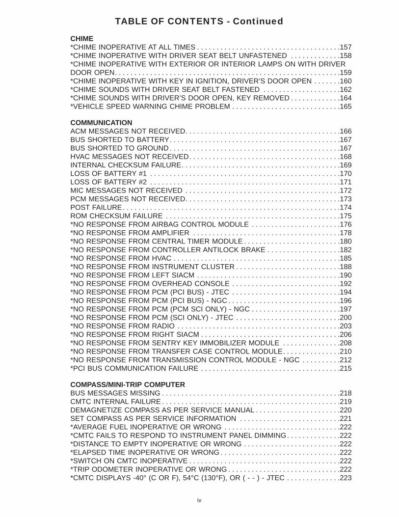


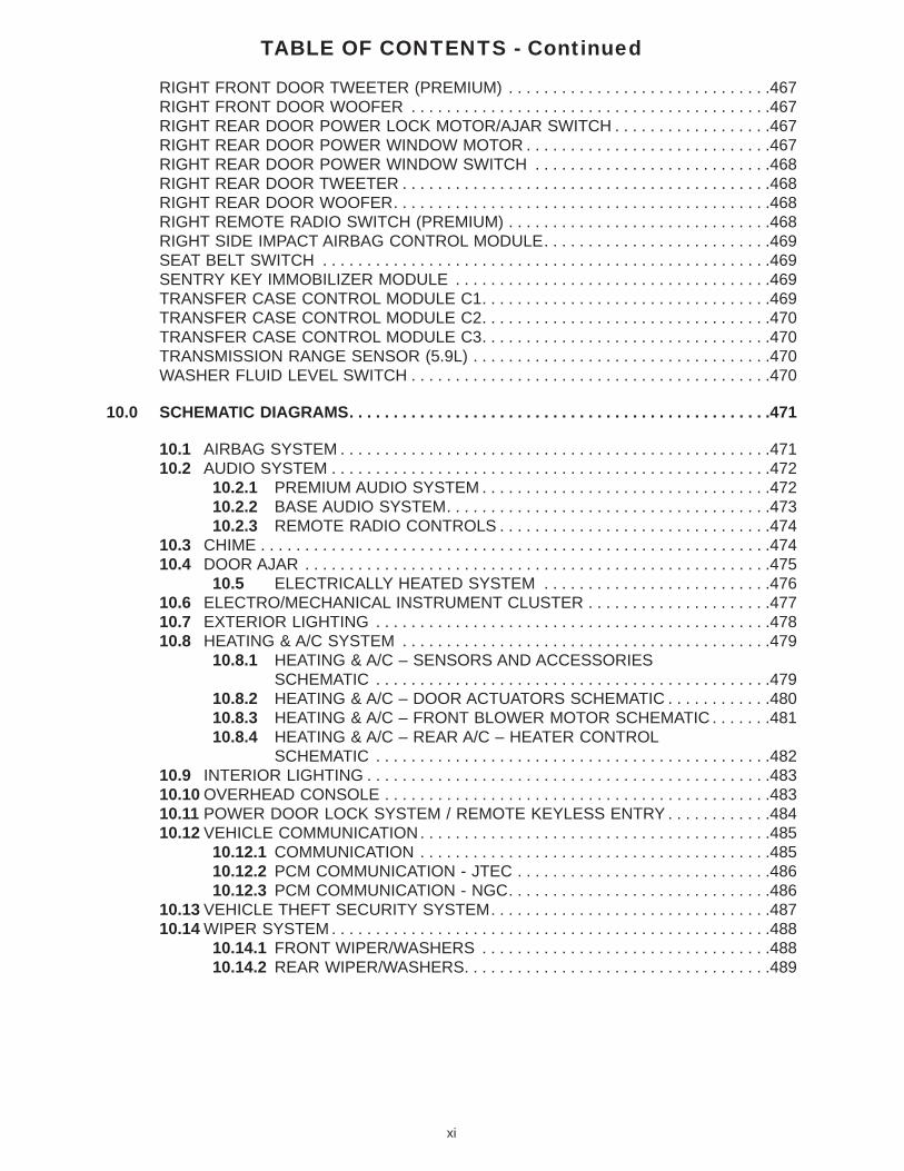


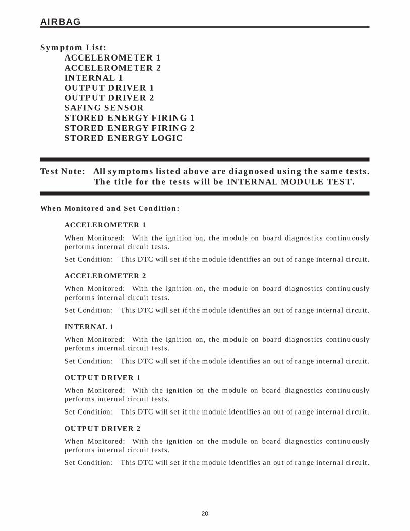
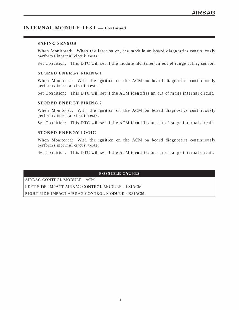


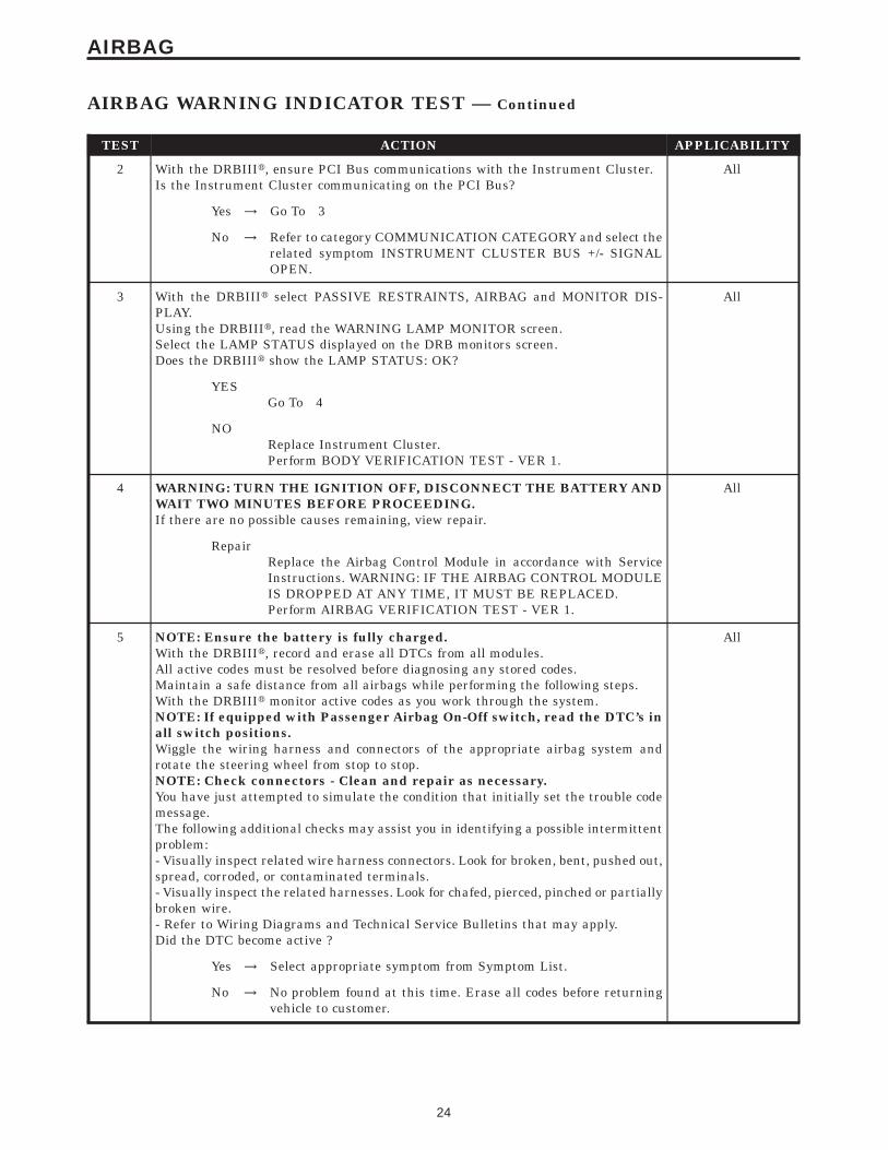


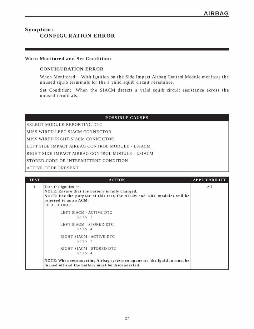


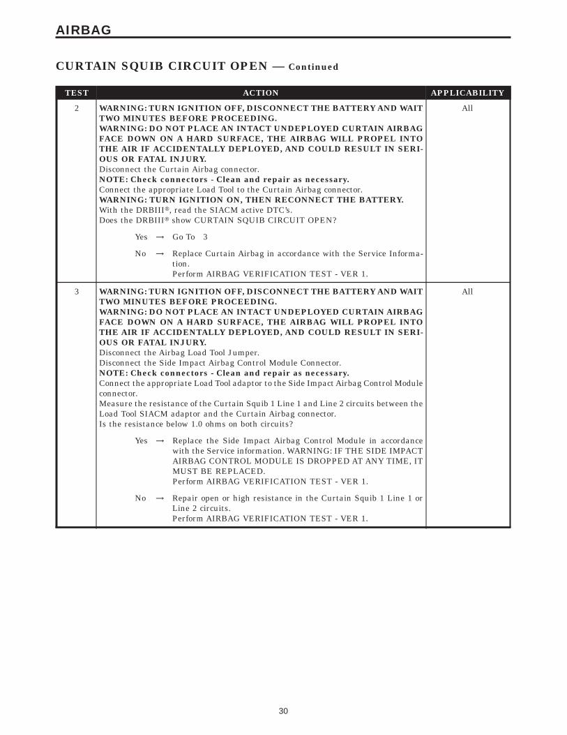


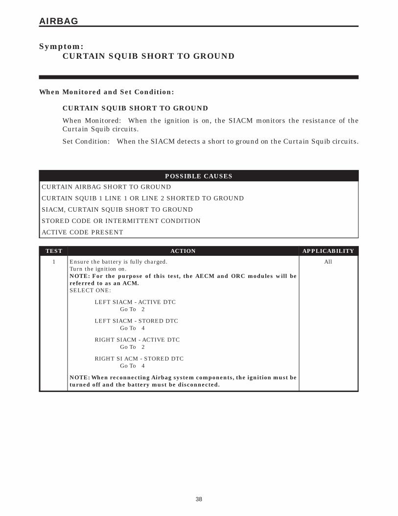


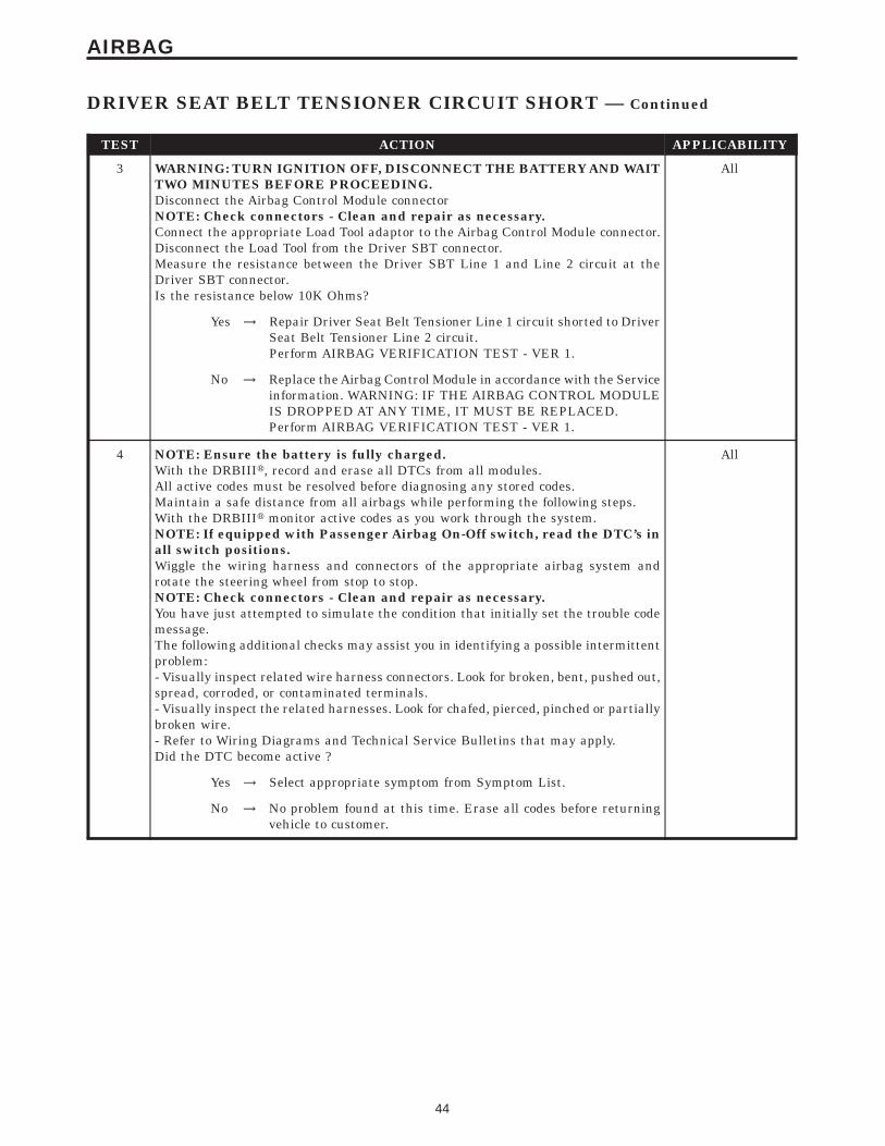


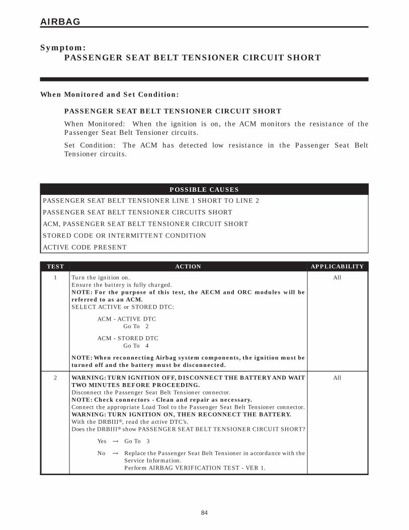


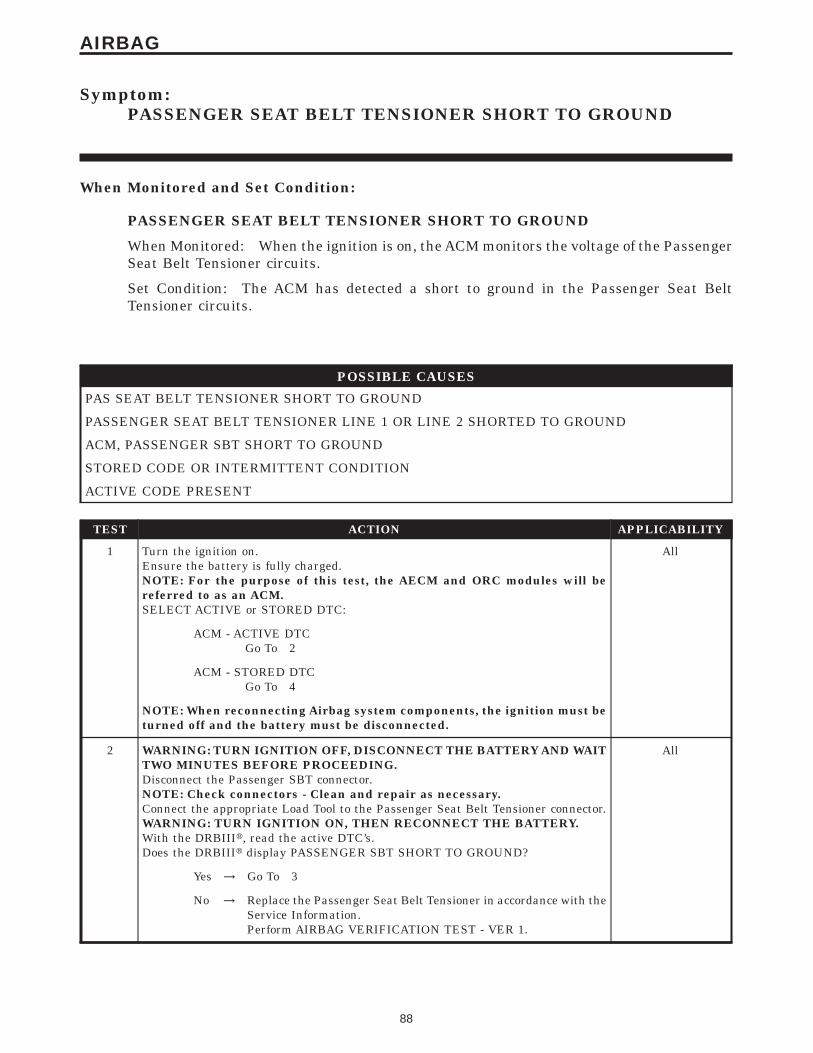


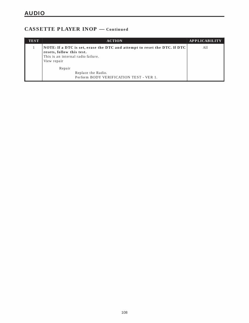


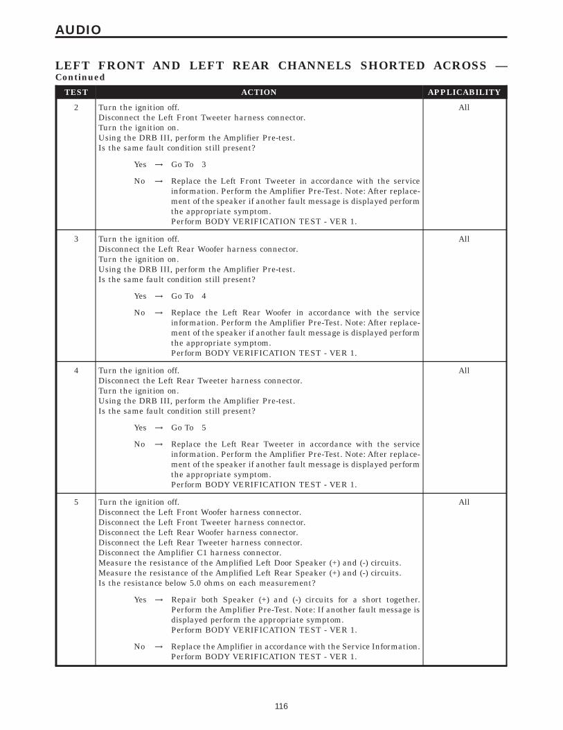


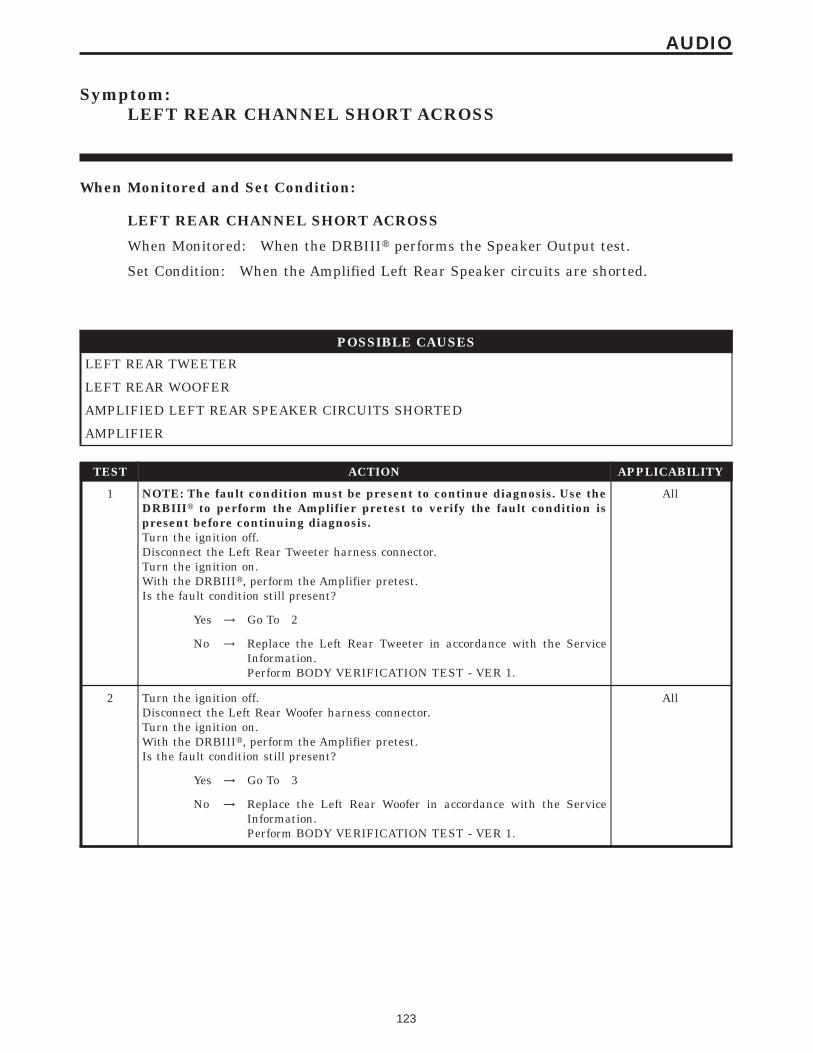


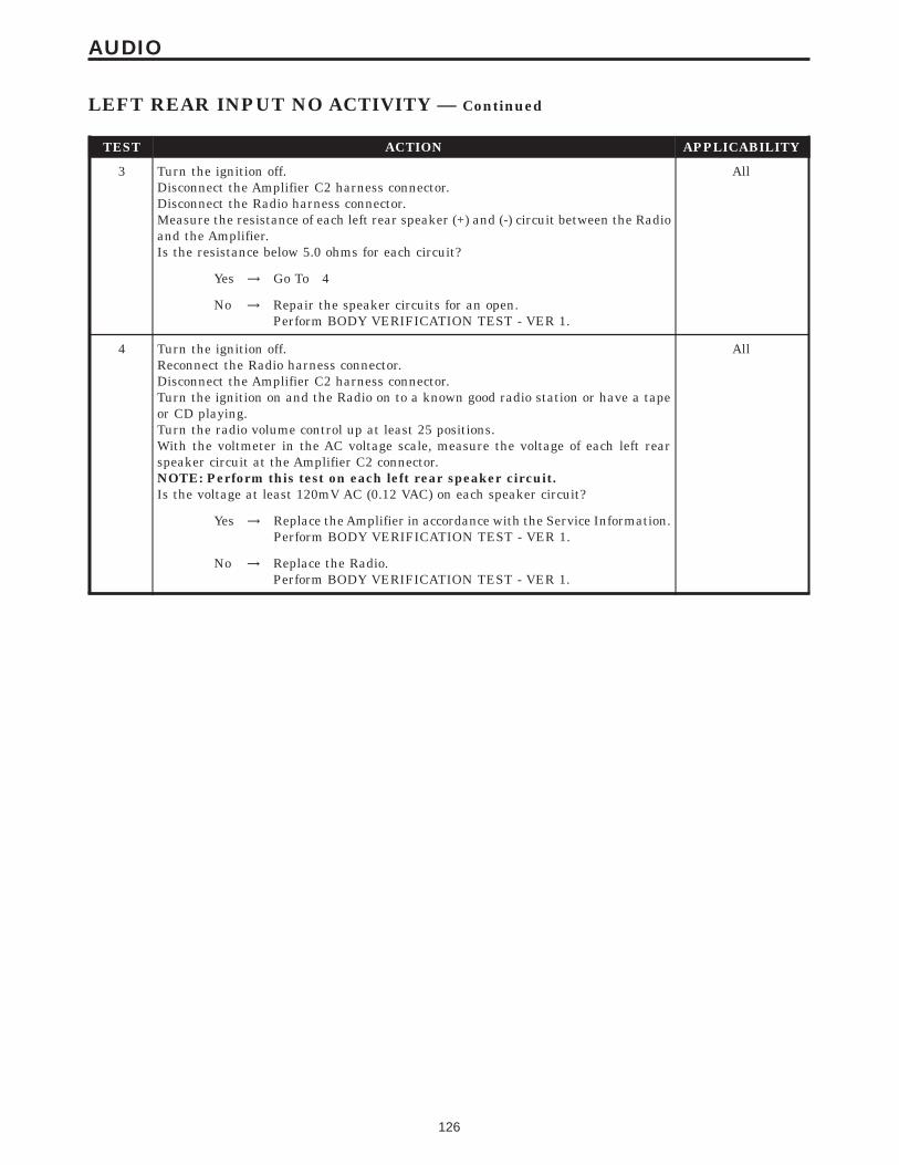


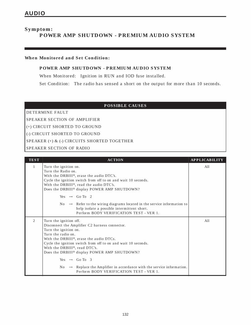


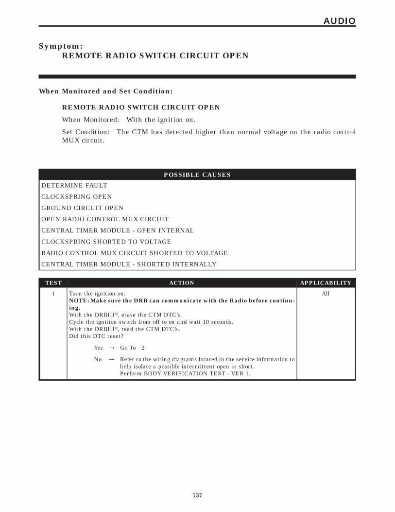


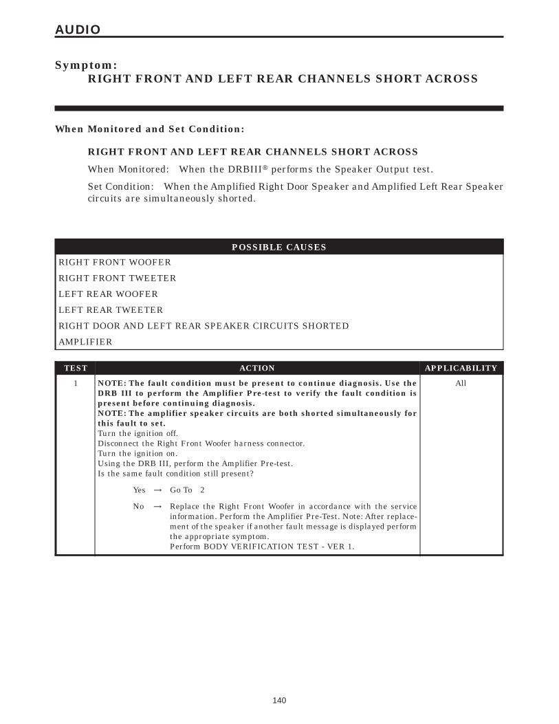


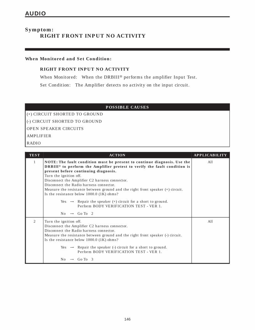


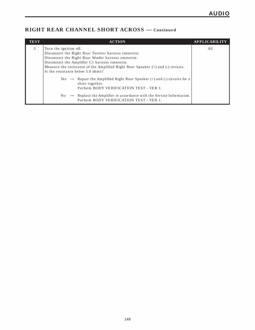


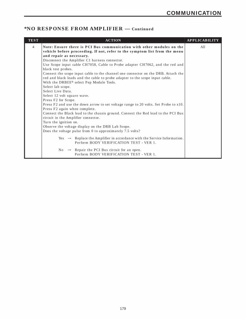


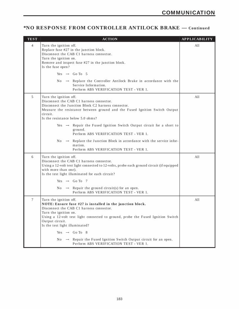


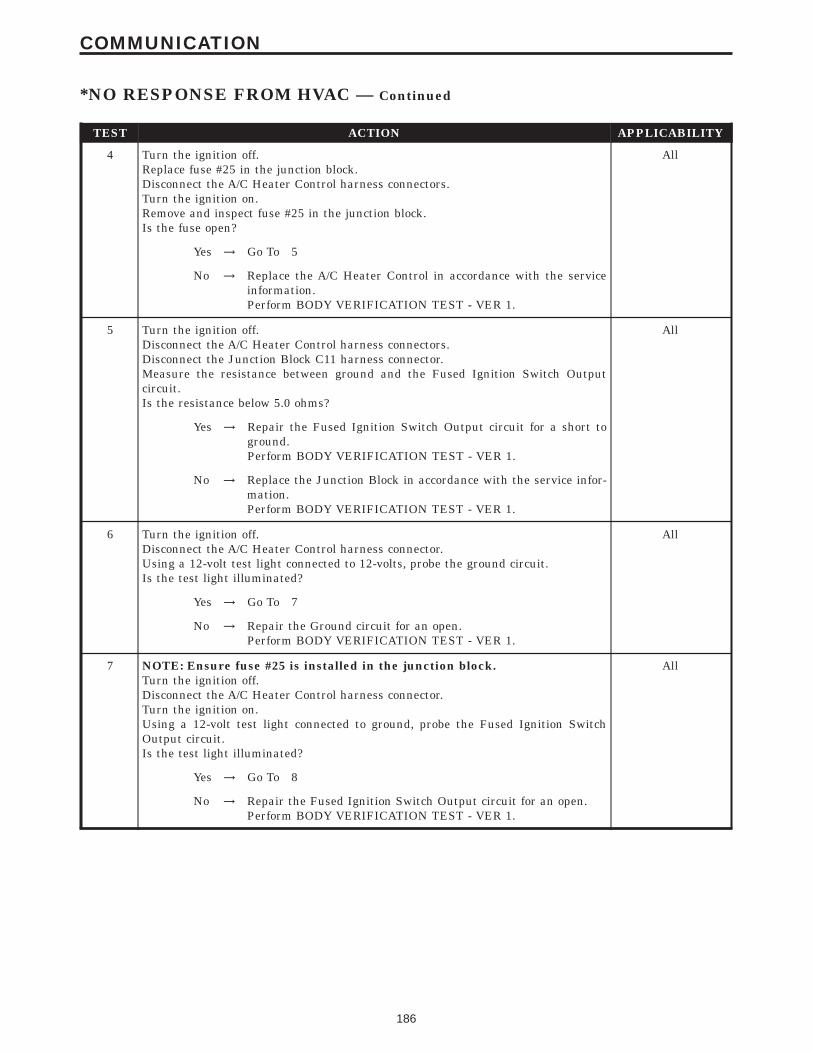


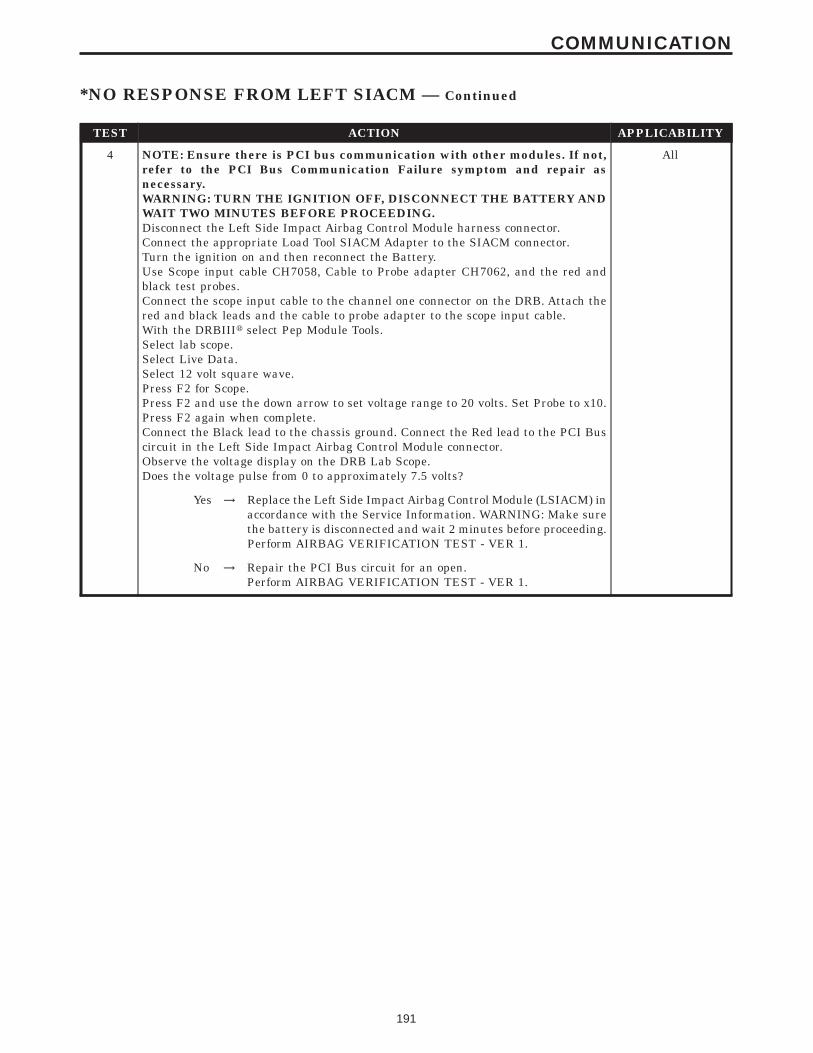
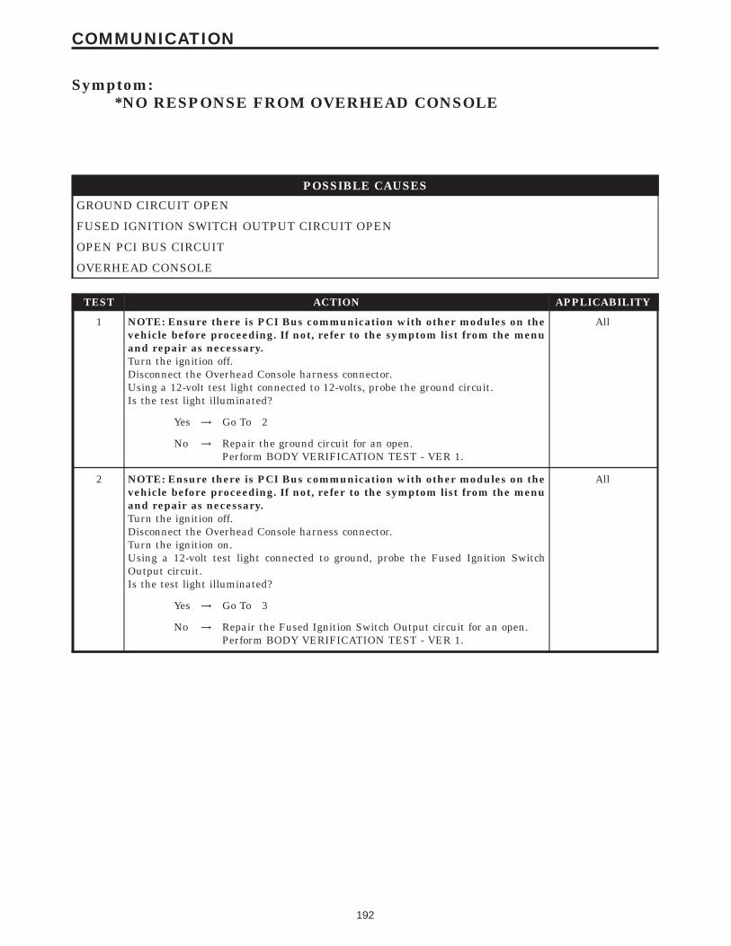


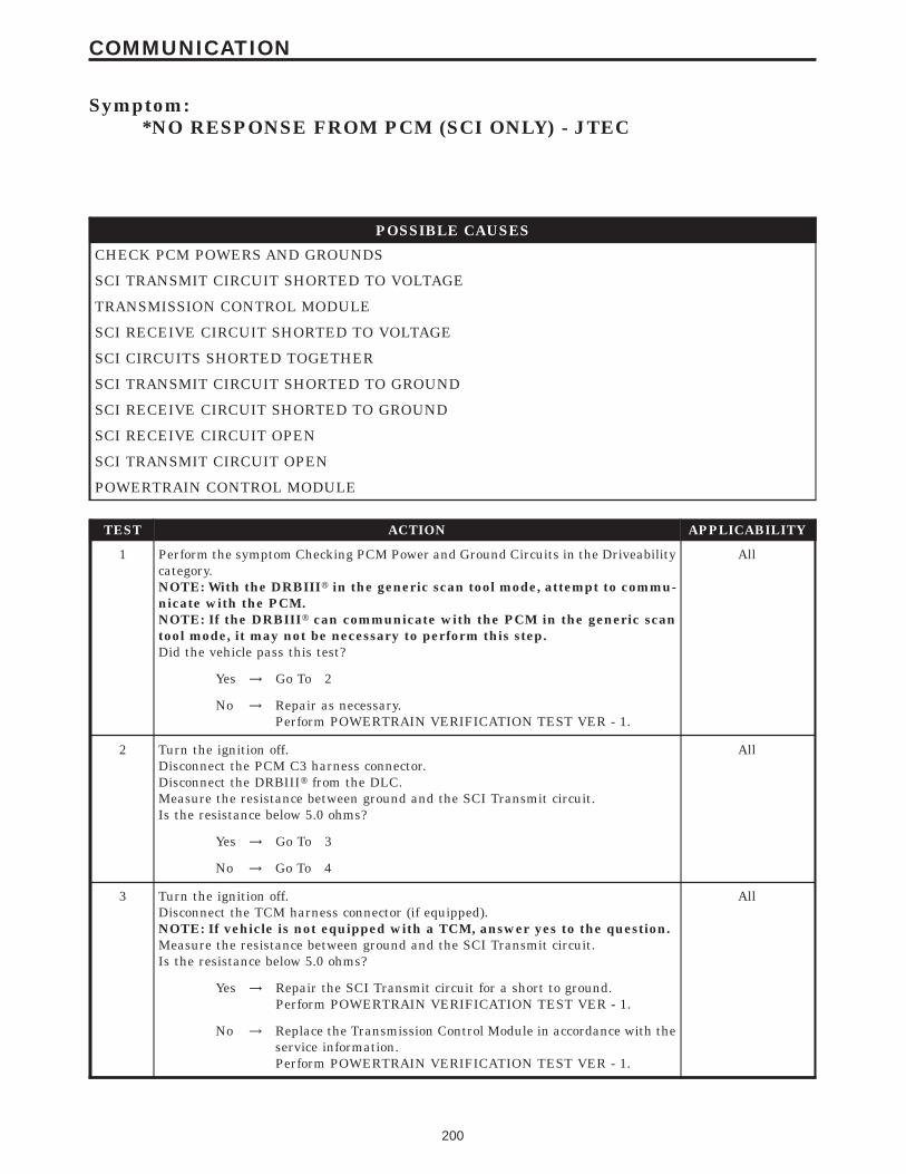


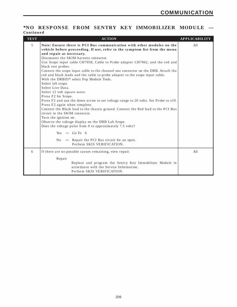

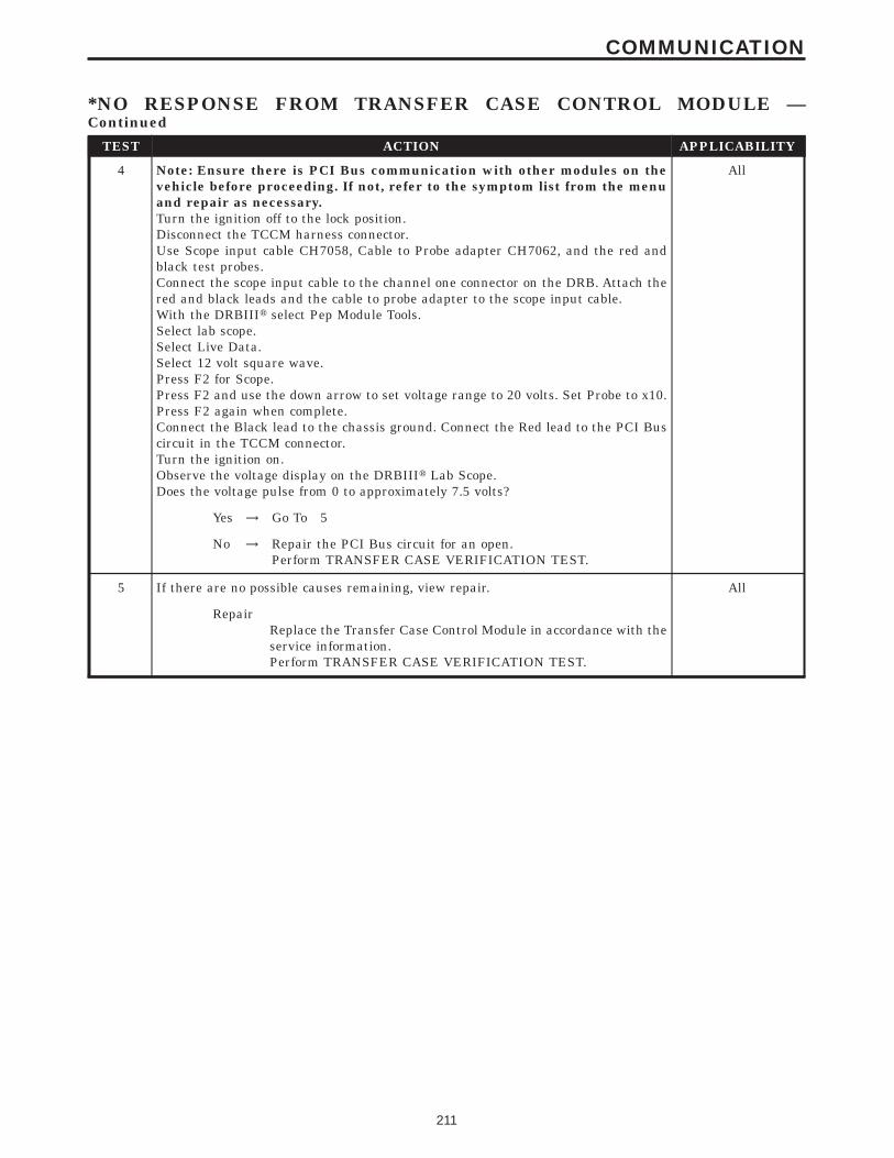


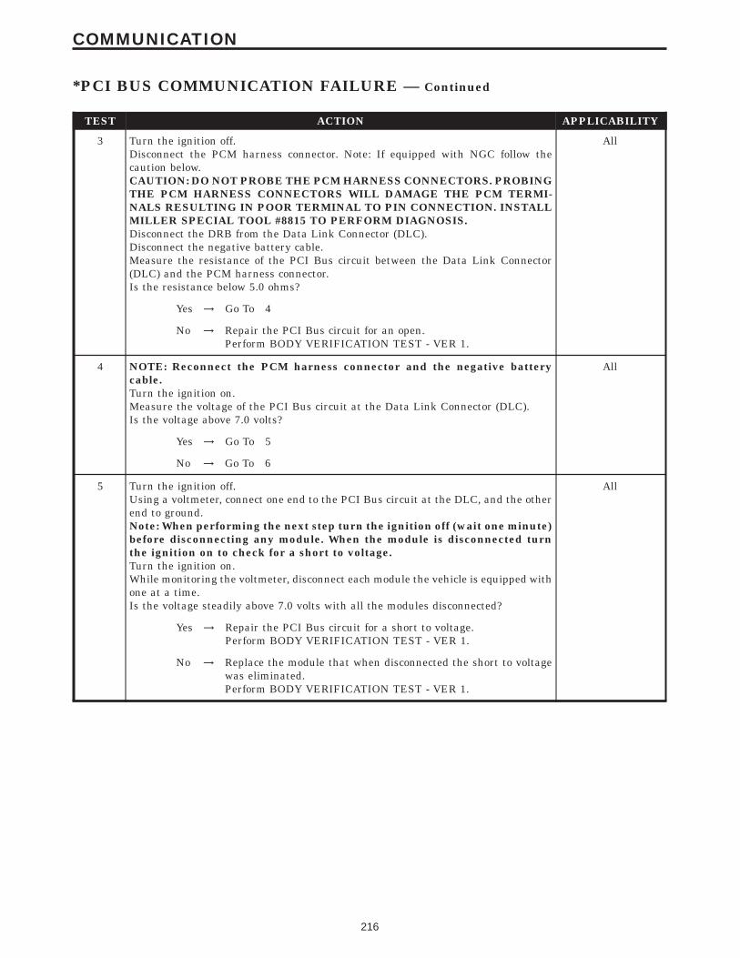


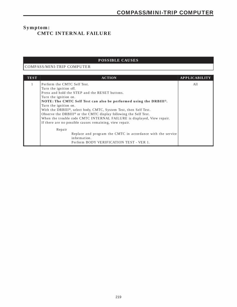

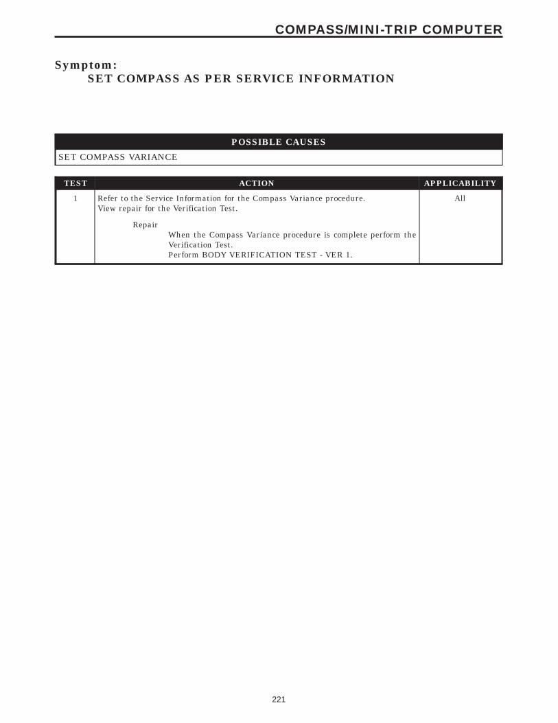


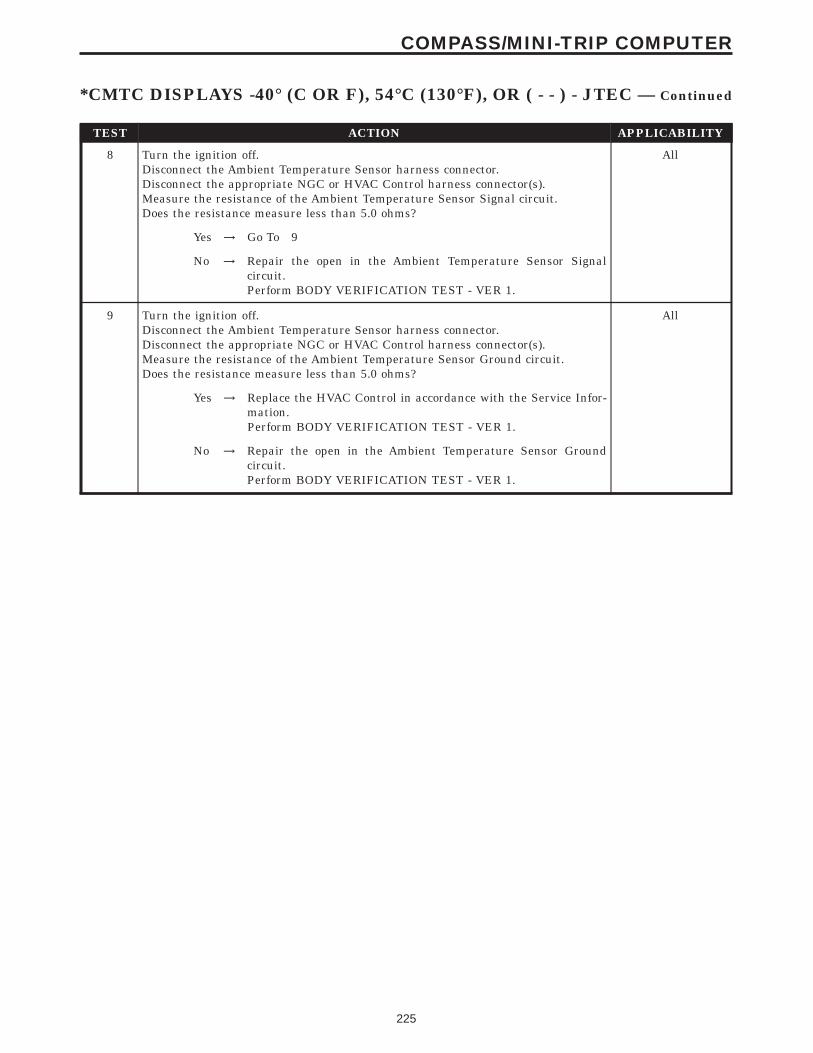


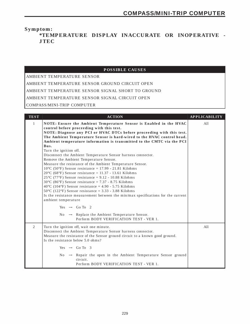


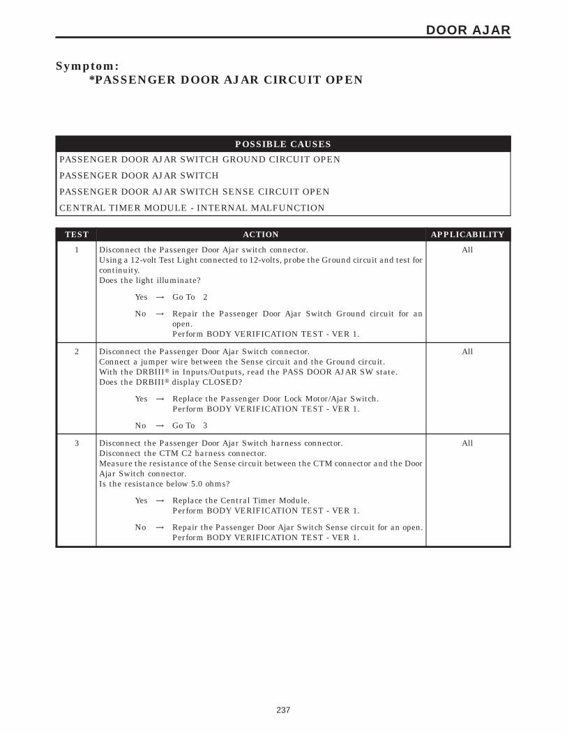


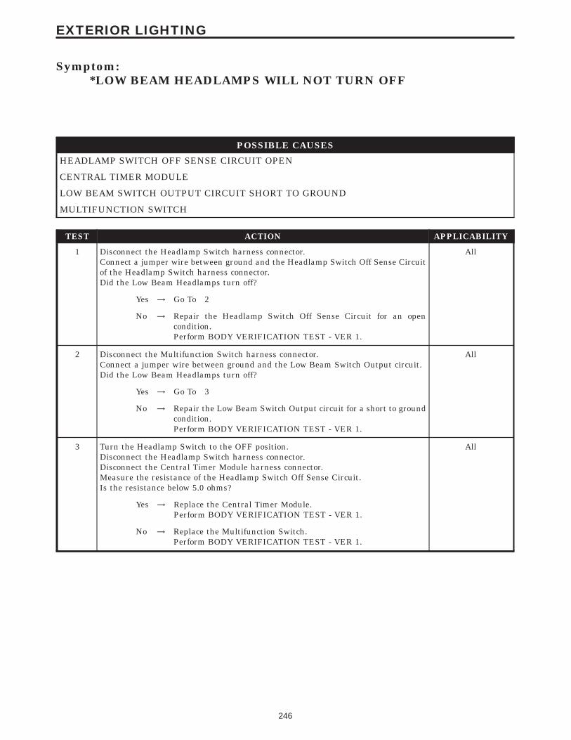


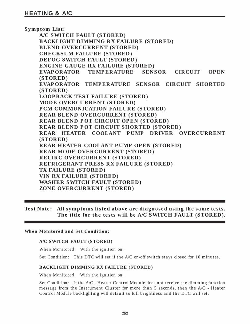


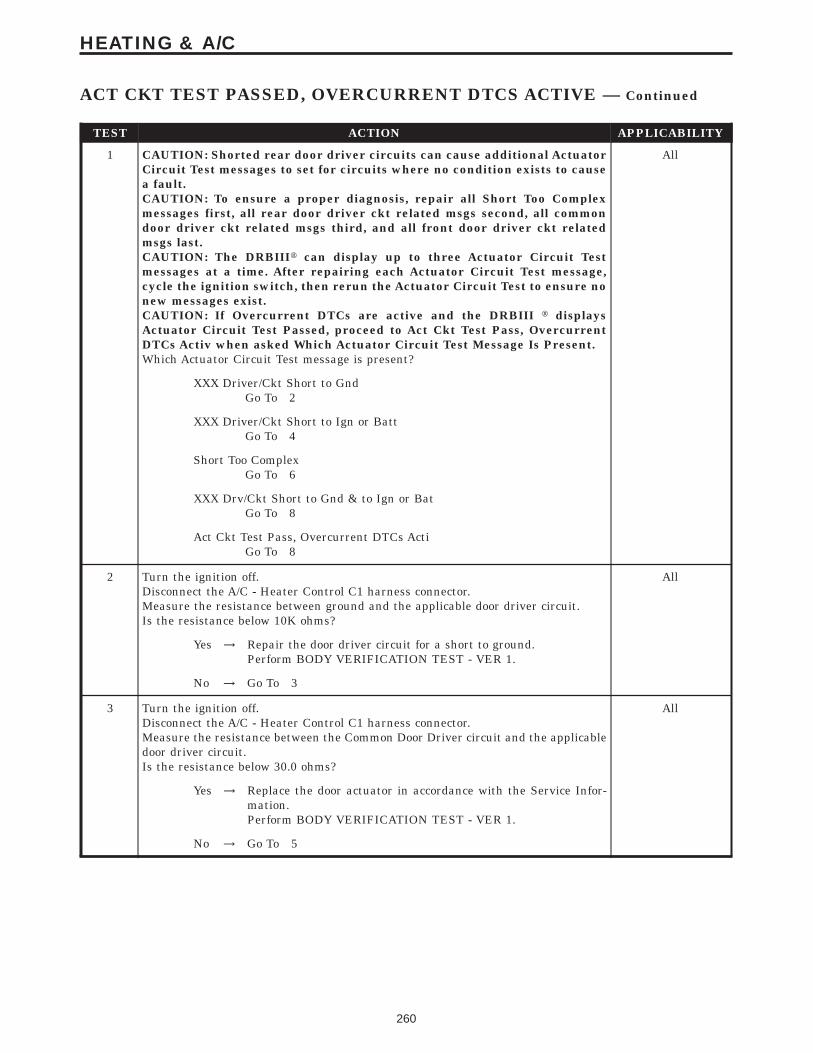


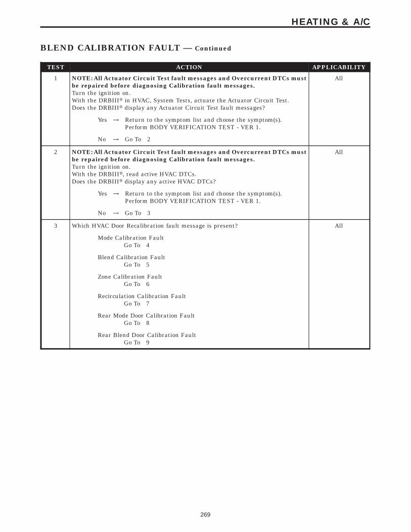

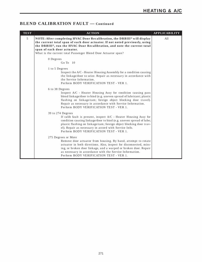
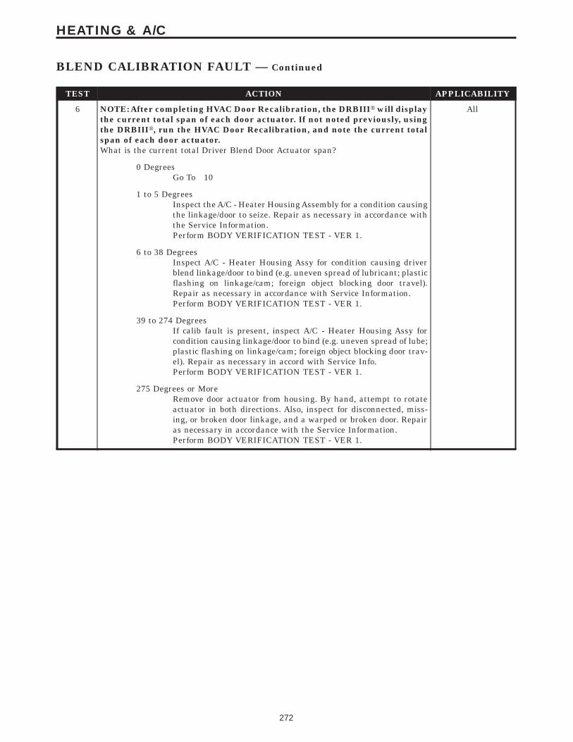


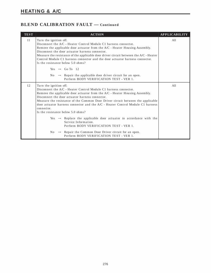


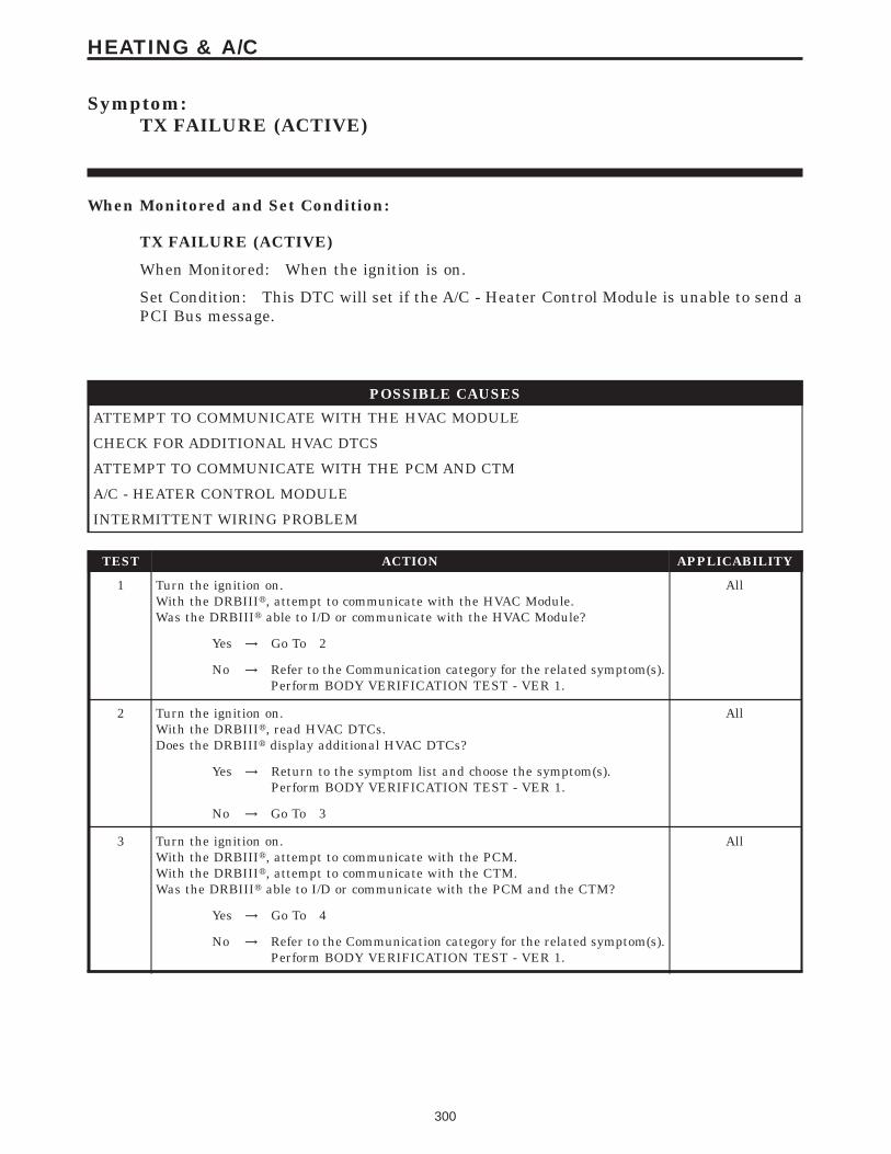


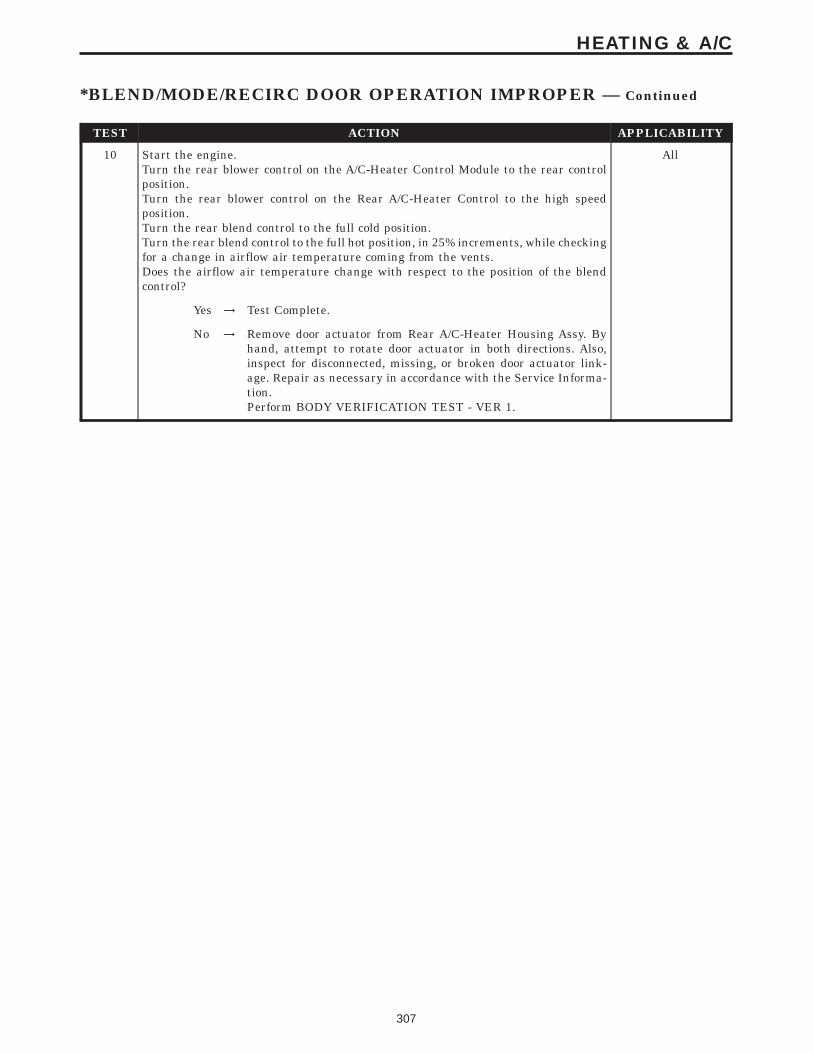
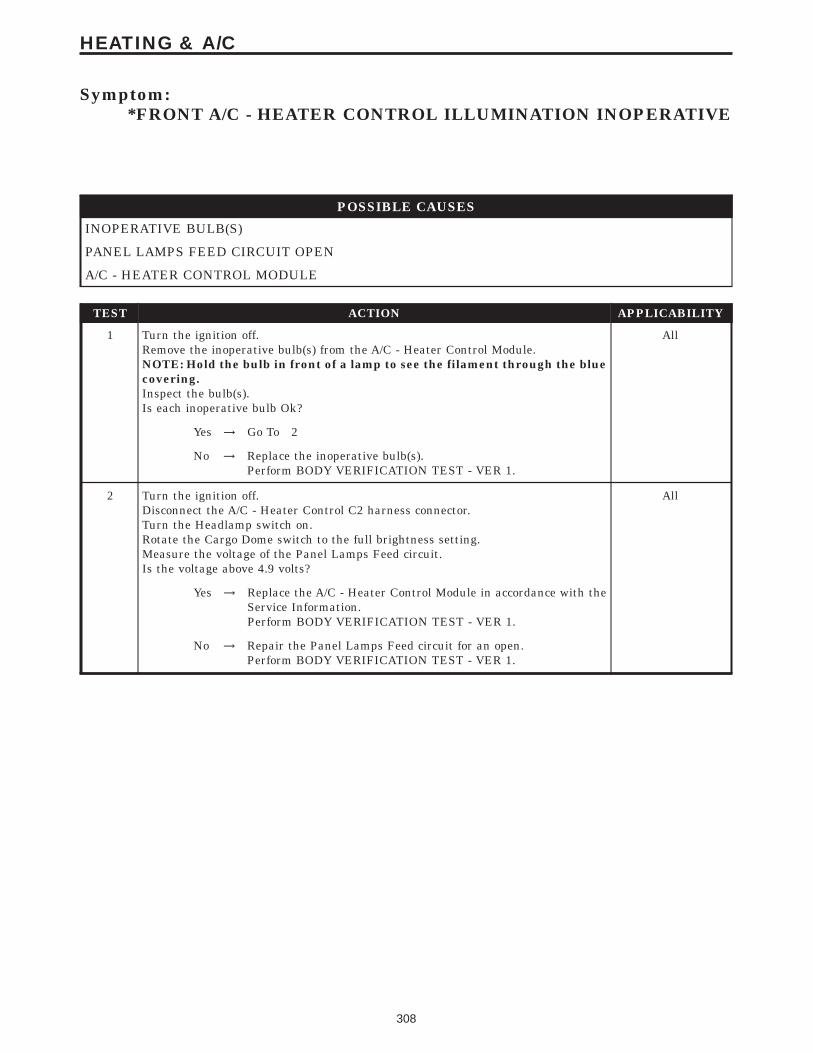

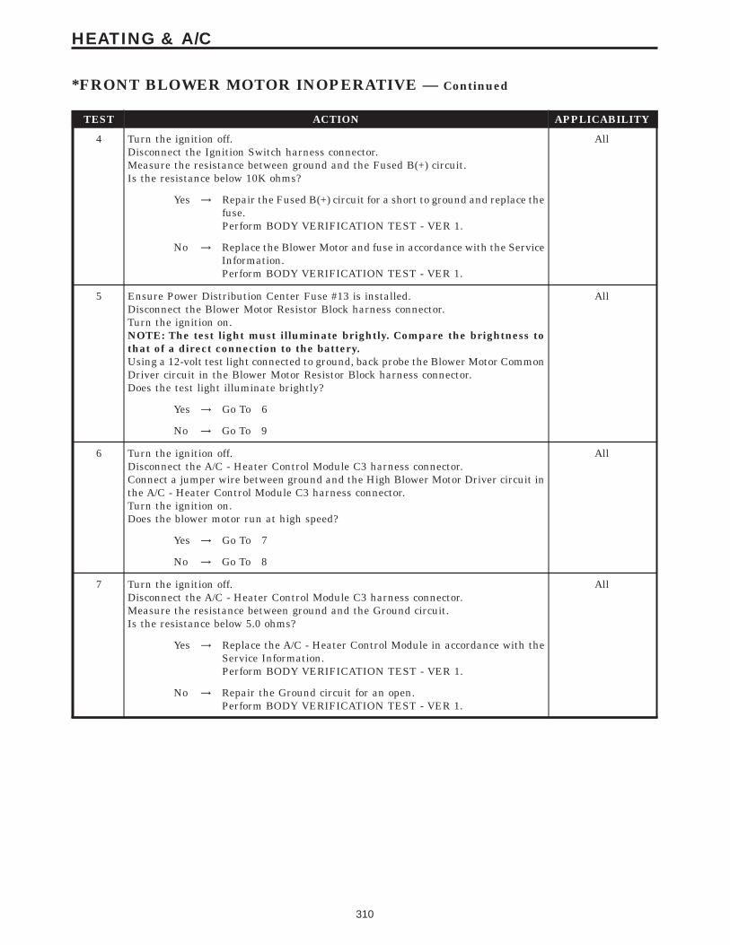

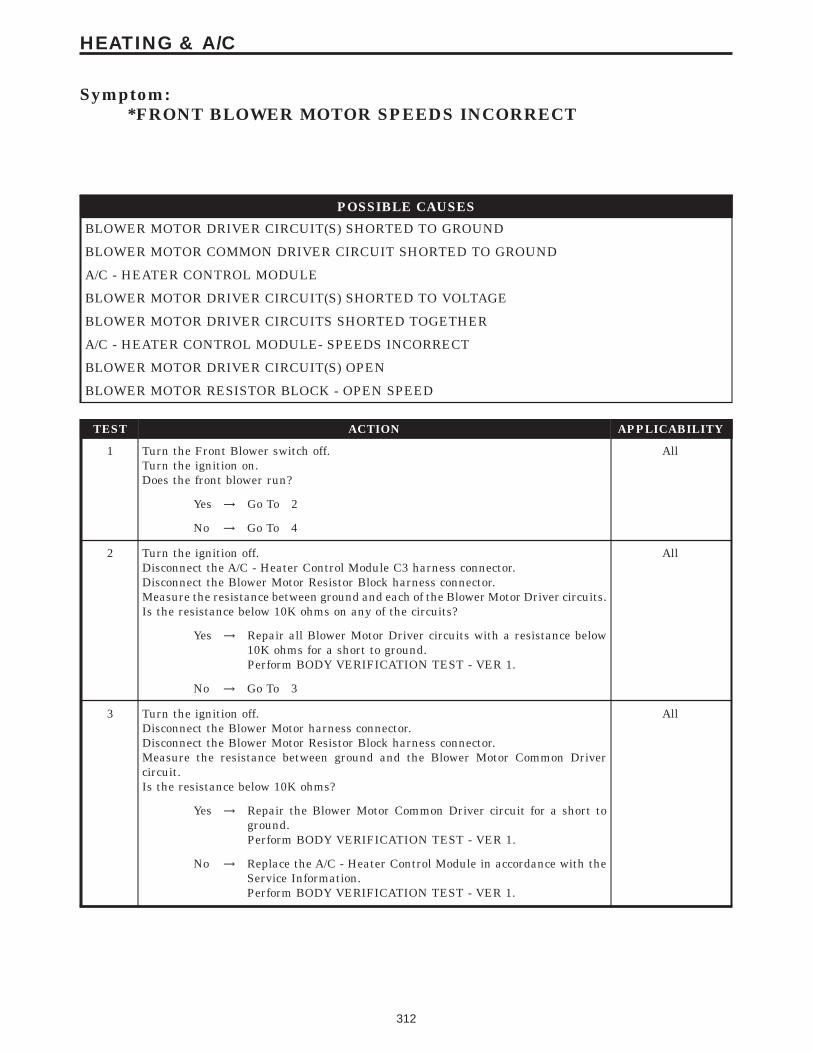


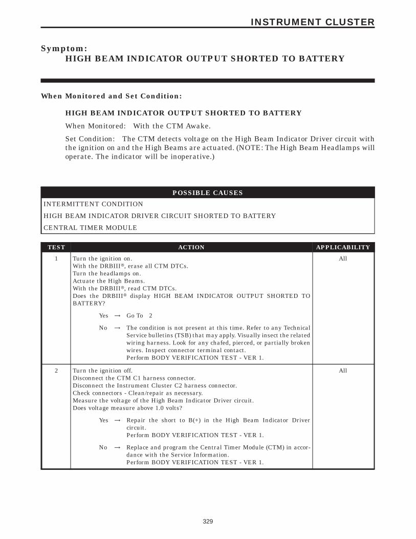

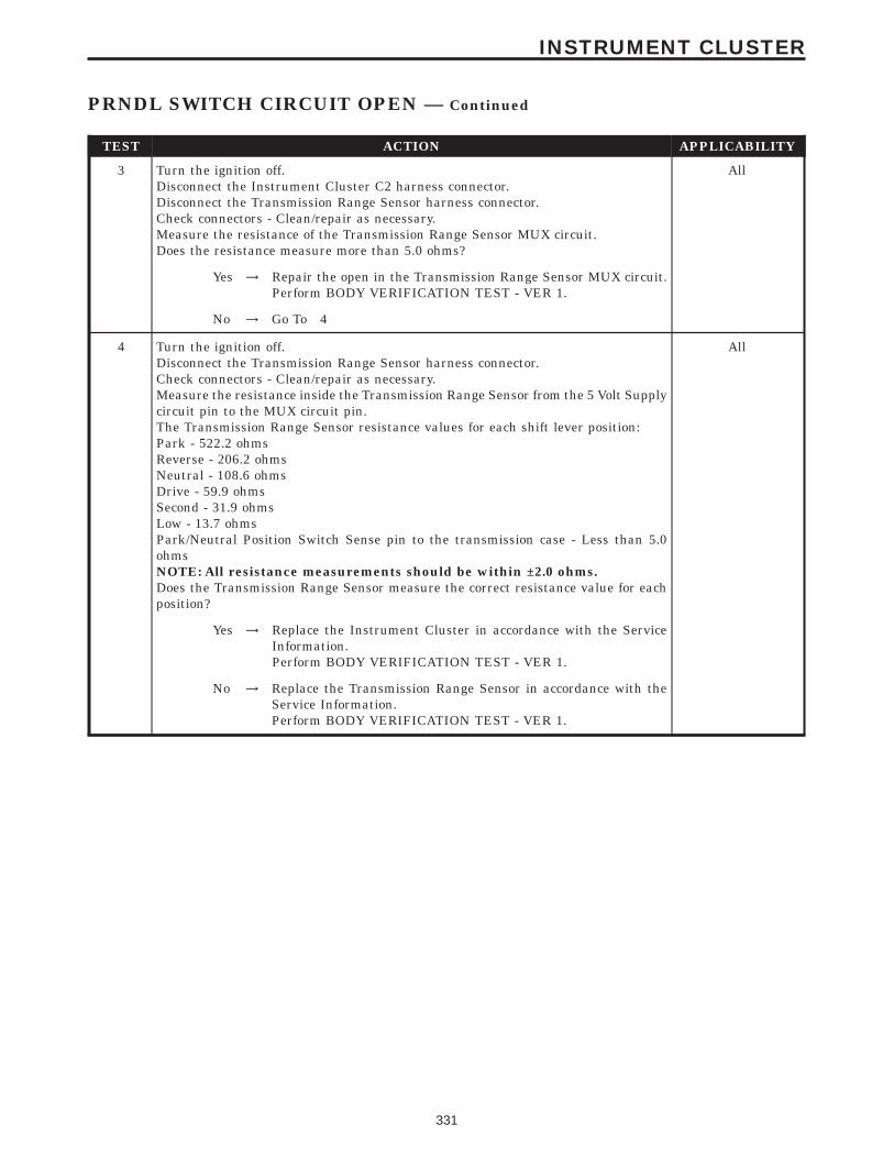


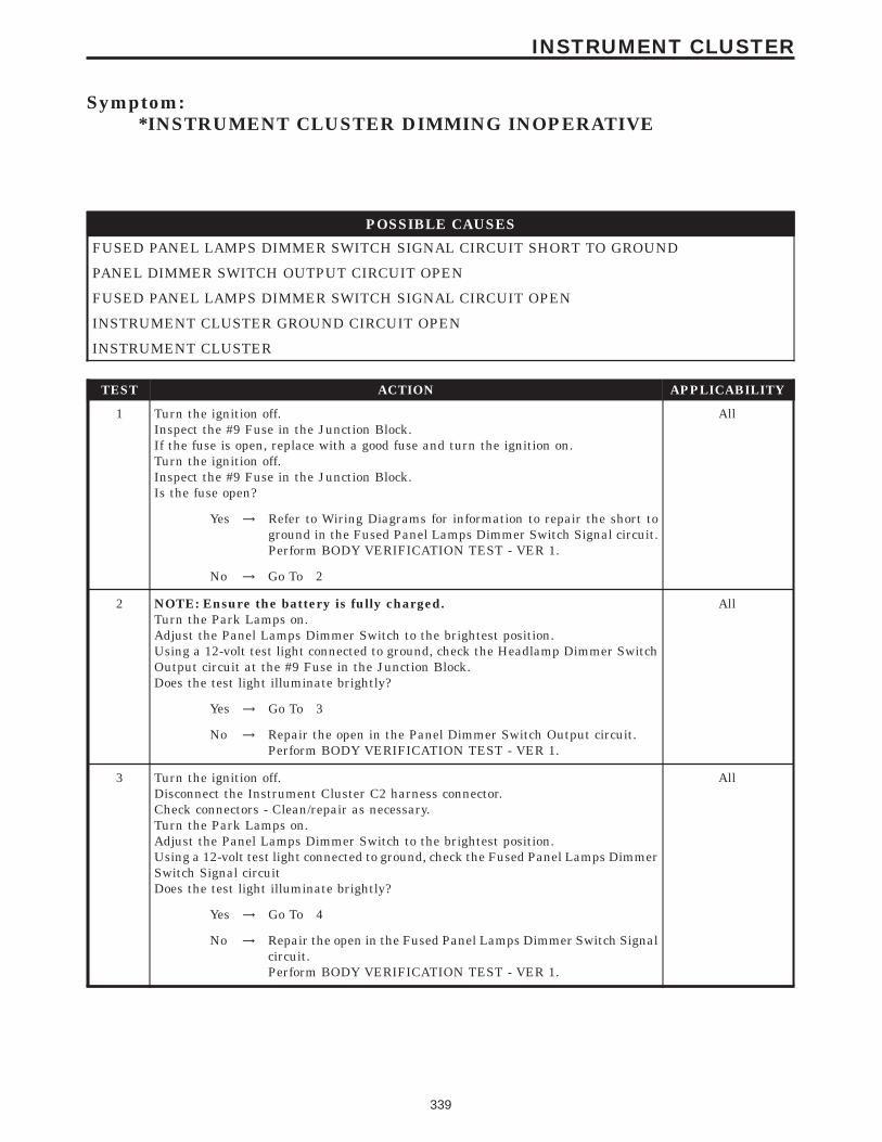


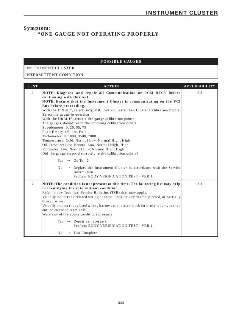


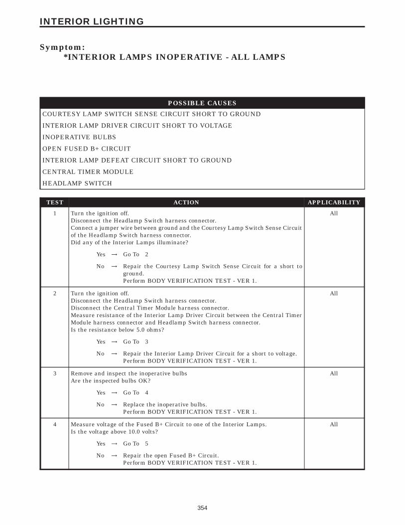


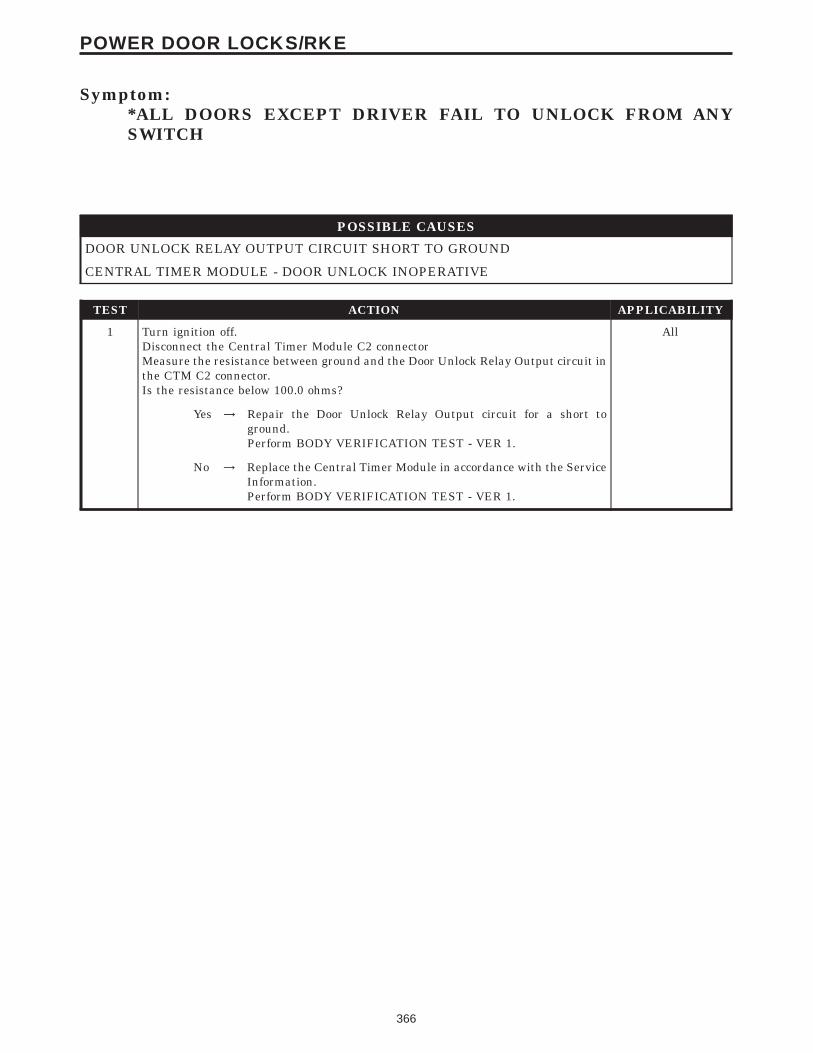


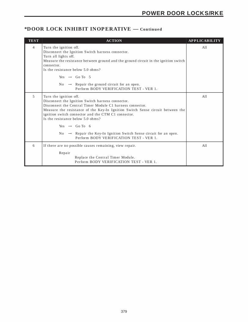


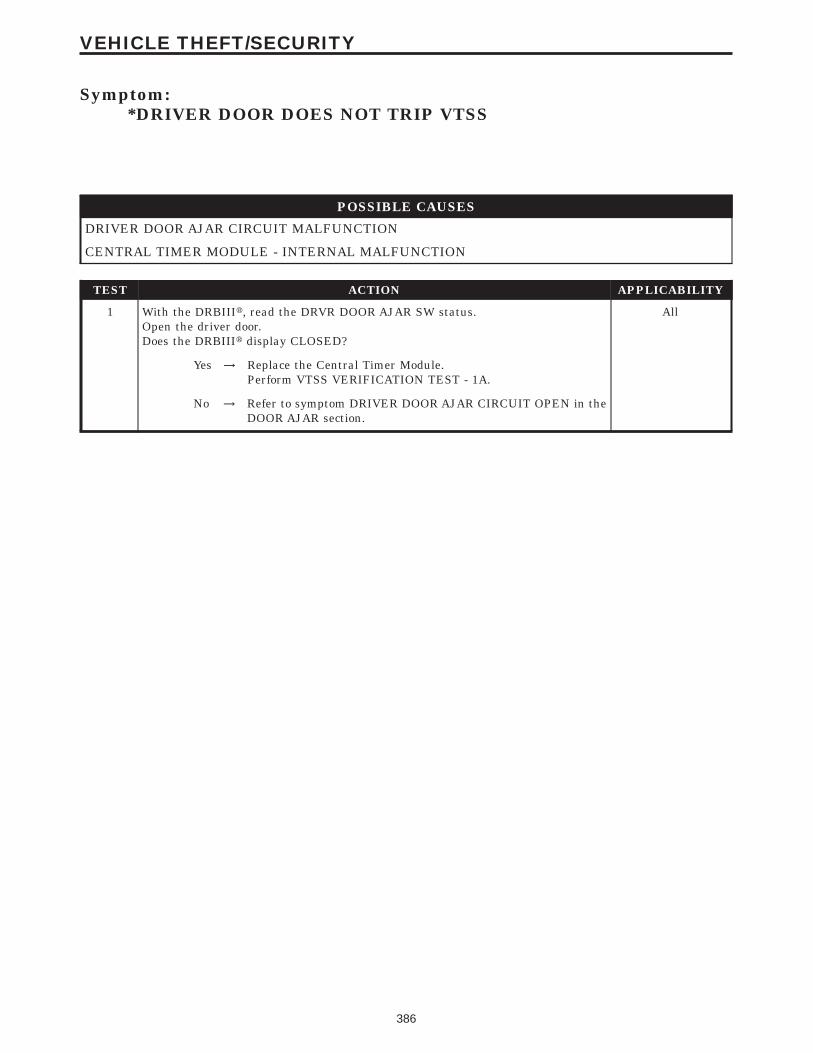


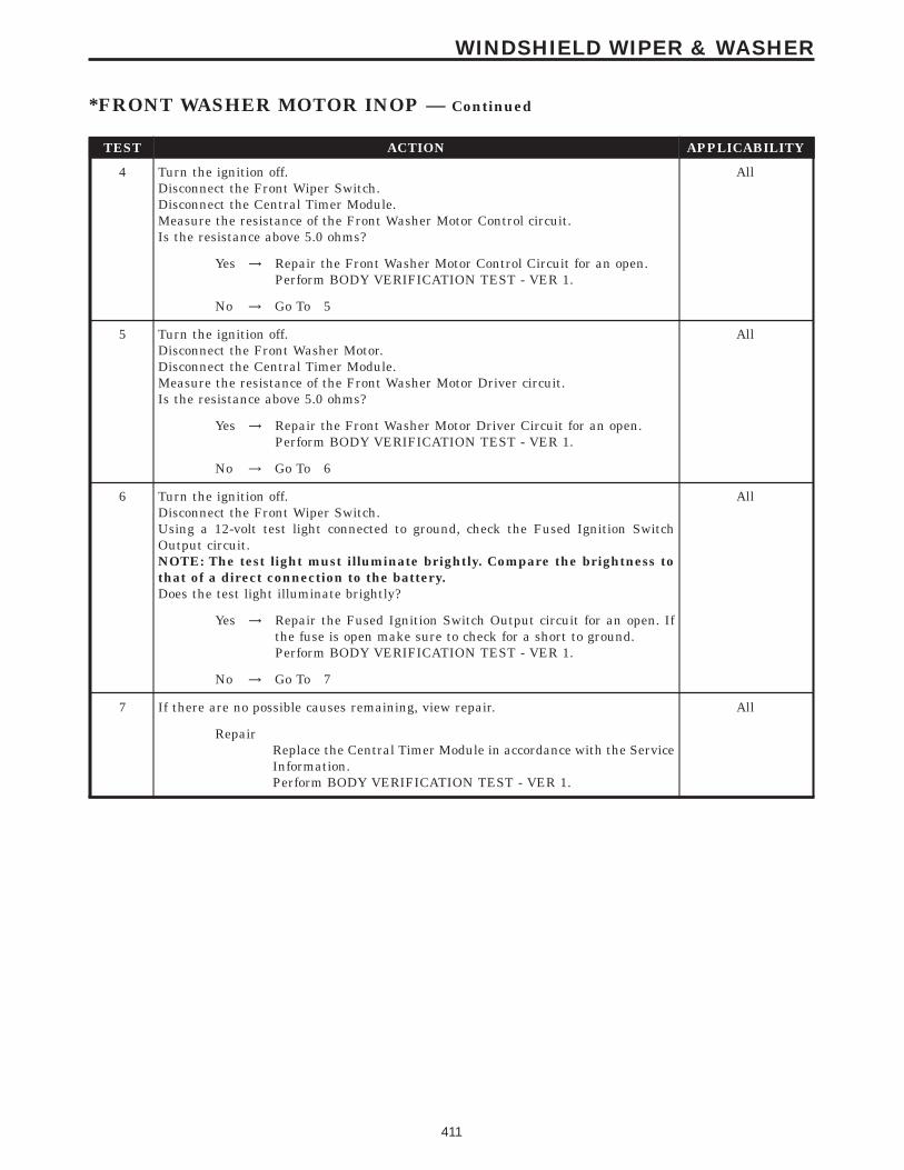


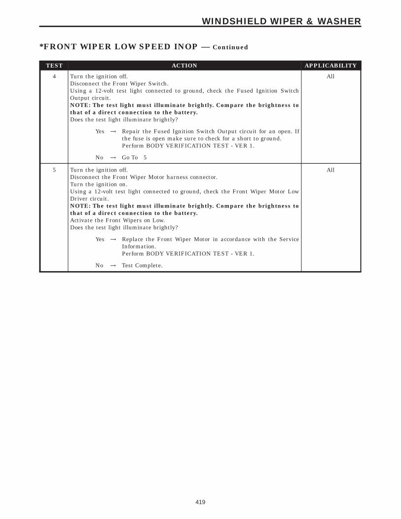


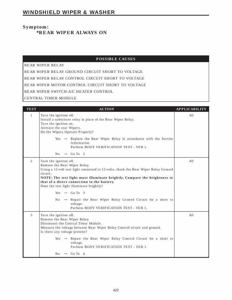
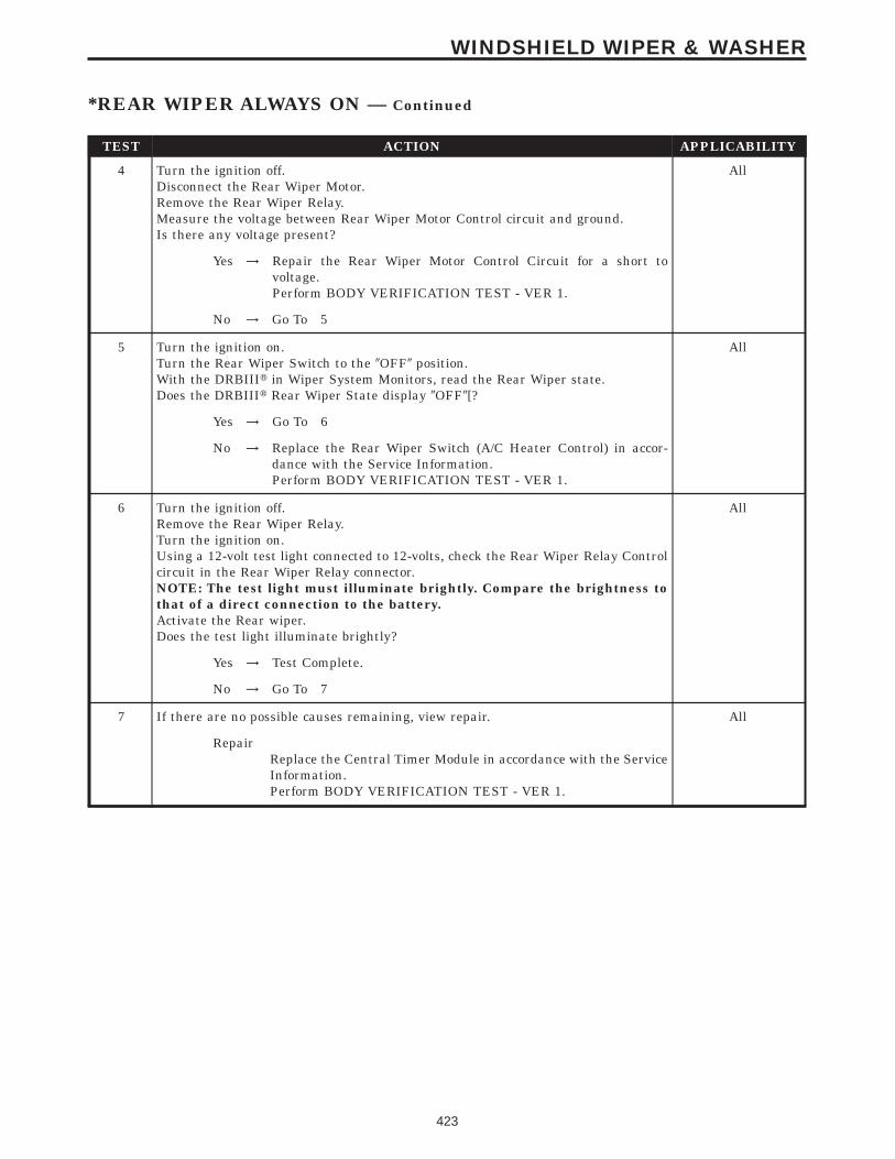
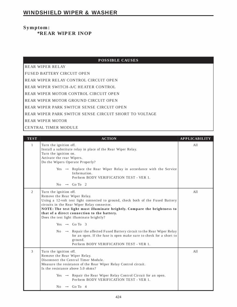


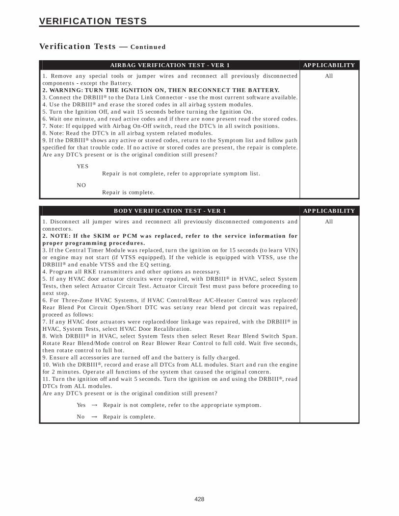


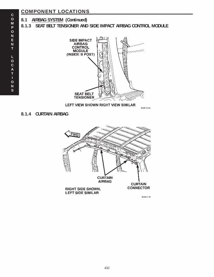


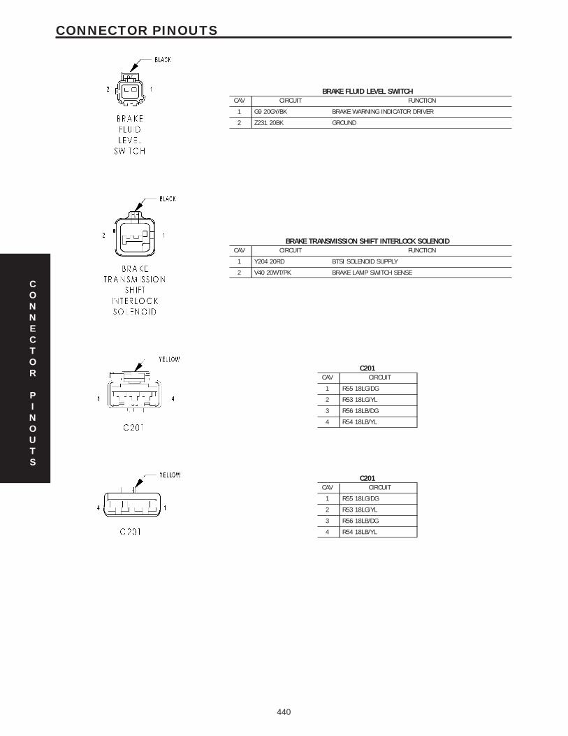


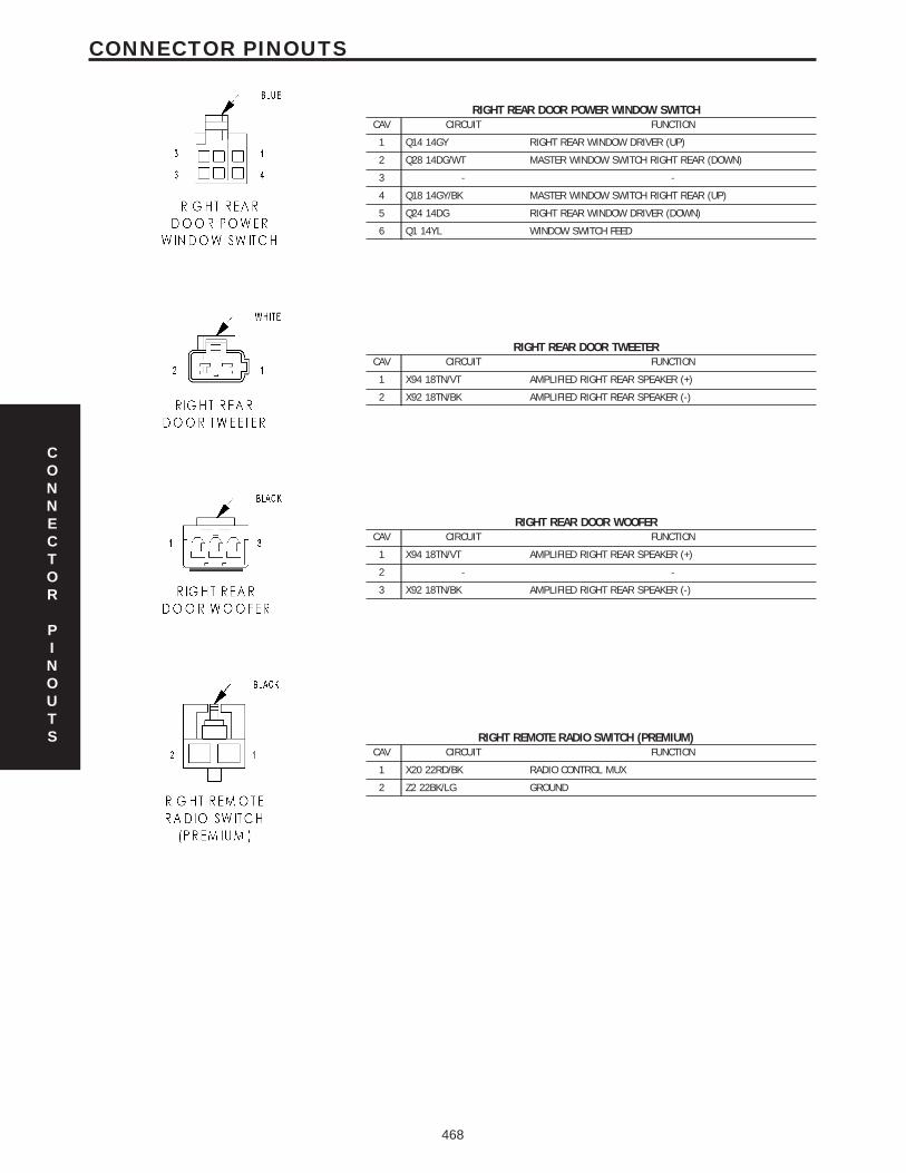


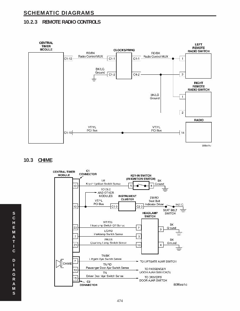


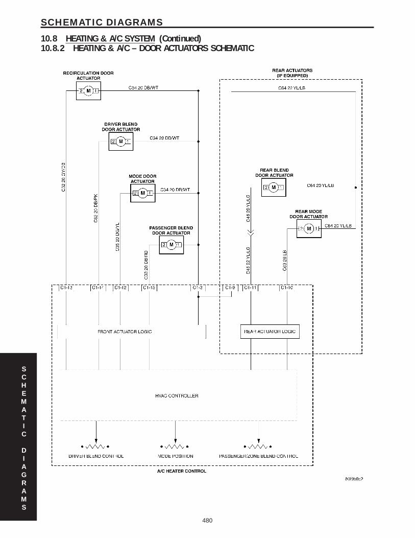

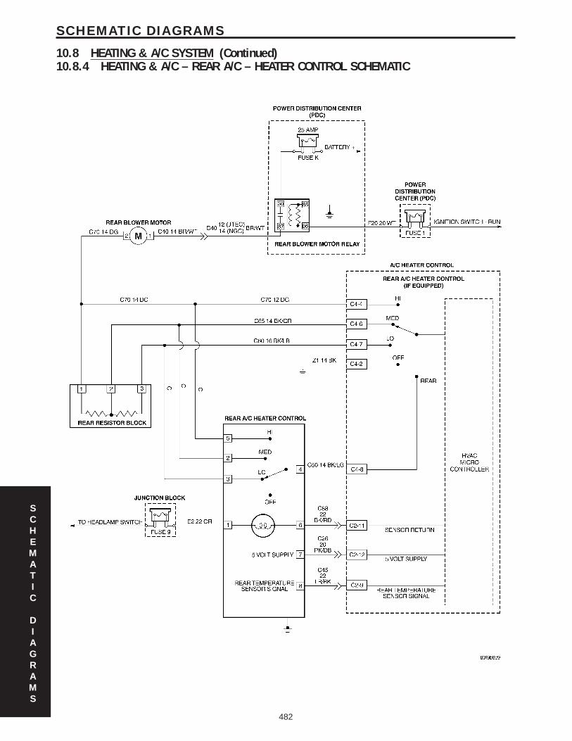

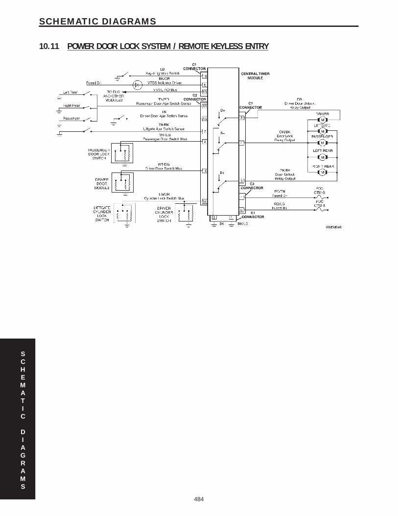


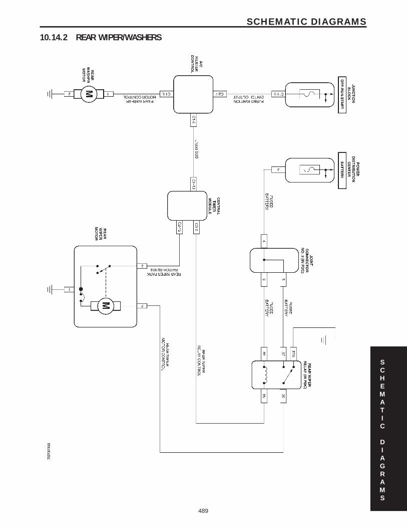


![index [teknik.trunojoyo.ac.id]teknik.trunojoyo.ac.id/ft_utm/images/Ari_Basuki_ST_MT/1 Jurnal JTEC... · of Batik SME in Bangkalan, Indonesia by applying the Learning Vector Quantization](https://static.documents.pub/doc/80x56/5c89ae8a09d3f2d4158ca0cd/index-jurnal-jtec-of-batik-sme-in-bangkalan-indonesia-by-applying-the.jpg)


