*TM 10-3930-643-10 TECHNICAL MANUAL OPERATOR’S MANUAL S/N 2000 AND BELOW S/N 2001 AND ABOVE TRUCK, FORKLIFT, DED PNEUMATIC TIRE, 10,000 LB. CAPACITY ROUGH TERRAIN, ARTICULATED FRAME STEER (DRESSER INDUSTRIES MODEL M10A, MHE 236) (NSN 3930-01-054-3833) TABLE OF CONTENTS Page i EQUIPMENT DESCRIPTION Page 1-6 OPERATING INSTRUCTIONS Page 2-1 PREVENTIVE MAINTENANCE Page 2-14 LUBRICATION INSTRUCTIONS Page 3-1 TROUBLESHOOTING PROCEDURES Page 3-4 MAINTENANCE PROCEDURES Page 3-12 SUBJECT INDEX Page Index-1 *This manual supersedes the Operator’s portion of TM 10-3930-643-14&P, dated 30 Nov 81 with all changes APPROVED FOR PUBLIC RELEASE. DISTRIBUTION IS UNLIMITED. Headquarters, Department of the Army 19 January 1990
Transcript
*TM 10-3930-643-10
TECHNICAL MANUALOPERATOR’S MANUAL
S/N 2000 AND BELOW
S/N 2001 AND ABOVE
TRUCK, FORKLIFT , DED
PNEUMATIC T IRE ,10,000 LB. CAPACITY
R O U G H T E R R A I N ,ART ICULATED FRAME STEER
( D R E S S E R I N D U S T R I E SMODEL M10A, MHE 236)(NSN 3930 -01 -054 -3833 )
TABLE OF CONTENTSPage i
EQUIPMENTDESCRIPTION Page 1-6
OPERATINGINSTRUCTIONS Page 2-1
PREVENTIVEMAINTENANCE Page 2-14
LUBRICATIONINSTRUCTIONS Page 3-1
TROUBLESHOOTINGPROCEDURES Page 3-4
MAINTENANCEPROCEDURES Page 3-12
SUBJECT INDEXPage Index-1
*This manual supersedes the Operator’s portion of TM 10-3930-643-14&P, dated 30 Nov 81 with all changes
APPROVED FOR PUBLIC RELEASE. DISTRIBUTION IS UNLIMITED.
Headquarters, Department of the Army 19 January 1990
WARNING
WARNING
WARNING
WARNING
TM 10-3930-643-10
ACCIDENTAL MOVEMENT
To prevent accidental movement of the forklift apply
parking/emergency brake, place transmission directional
lever in neutral position and lock, before starting
engine.
ARTICULATION HAZARD
Before checking transmission oil level, make sure that
the frame locking bar is pinned securely to prevent
articulation.
BURN HAZARD
Allow engine to cool before performing maintenance on
the muffler, exhaust pipe, exhaust manifold or turbo-
charger. If necessary, use insulated pad or gloves.
Failure to follow this procedure could cause SEVERE
INJURY .
CHEMICAL BURN HAZARD
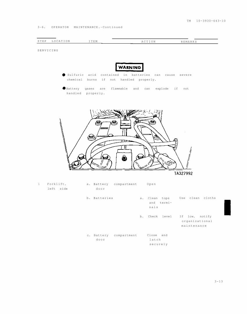
Sulfuric acid contained in batteries can cause severe
chemical burns. Wear protective goggles and gloves when
working with batteries. Avoid contact with eyes, skin or
clothing. If the electrolyte is spilled, take immediate
action to stop its burning effects:
EYES : Flush with cold water for 15 minutes.
Seek medical attention immediately.
INTERNAL: Drink large amounts of water or milk.
Follow with milk of magnesia, beaten
egg, or vegetable oil. Seek medical
attention immediately.
EXTERNAL: Flush with cold water until all acid
has been removed.
CLOTHING OR
VEHICLE: Wash with cold water at once.
Neutralize acid with baking soda or
household ammonia solution.
a
WARNING
WARNING
WARNING
TM 10-3930-643-10
COMPRESSED AIR HAZARD
Compressed air used for cleaning purposes will not
exceed 30 psi. Use only with effective chip guarding and
personal protective equipment (goggles/shield, gloves,
etc.).
EMERGENCY BRAKING
If emergency brake must be used to stop forklift,
prepare for sudden stop and brace yourself to prevent
serious head, neck and back injuries.
EXHAUST GASES CAN BE DEADLY
Exhaust gases can produce symptoms of headache,
dizziness and loss of muscular control. DEATH, coma or
permanent brain damage can result from severe exposure.
You can insure your safety by following these rules:
. Do not operate the heater or engine in enclosed
areas unless the area is properly ventilated.
• If you notice exhaust odors or exposure systoms,
IMMEDIATELY VENTILATE the area.
• Remove affected personnel and take the following
actions:
• Expose affected personnel to fresh air.
• If necessary, administer artificial
respiration.
❵• Keep affected personnel warm.
• Do not permit physical exertion.
• Seek medical attention immediately.
Refer to FM 21-11, First Aid for Soldiers, for first aid
treatment of injured personnel.
b
WARNING
WARNING
WARNING
WARNING
WARNING
WARNING
TM 10-3930-643-10
MAINTENANCE PERSONNEL SAFETY
Unless otherwise specified, perform all maintenance
procedures with all equipment lowered to the ground,
transmission in neutral, parking/emergency brake
applied and the engine stopped.
FIRE HAZARD
Diesel fuel and combustible materials are used in the
operation and maintenance of this equipment. Do not
smoke or allow open flames or sparks in areas where
diesel fuel or combustible materials are used or stored.
Failure to follow this procedure could cause DEATH or
SERIOUS INJURY.
FLAMMABLE
Battery gases are flammable and can explode. Do not
smoke or allow open flames or sparks near batteries.
Failure to follow this procedure could result in DEATH
or SERIOUS INJURY.
LOSS OF CONTROL
When traveling downhill, never shift transmission into
neutral. You could lose control of the forklift and be
seriously injured.
LOSS OF STEERING
Be sure that the frame locking bar is removed before
operating vehicle. Failure to do so will cause loss of
steering control, which may result in DEATH or SERIOUS
INJURY .
NOISE HAZARD
Noise level exceeds 85 dB(A) at three feet in front, 15
feet to the side and 24 feet to the rear of the vehicle.
All personnel will wear hearing protection when operat-
ing or performing maintenance on the vehicle. Failure to
follow this procedure could cause serious hearing
damage.
c
WARNING
WARNING
WARNING
WARNING
WARNING
TM 10-3930-643-10
OPERATOR SAFETY
Before starting engine and operating forklift be thor-
oughly familiar with the information in this manual.
Also review all warnings and safety precautions.
OVERLOAD
Do not overload. Do not tilt load beyond vertical
position on mast when elevated, unless load is over a
stack. Failure to follow this procedure could result in
DEATH or SERIOUS INJURY.
PERSONAL SAFETY HAZARD
Stay clear of any and all moving parts of the forklift
when boom and forks are not lowered to the ground. U s e
extreme caution to prevent SERIOUS INJURY while
performing maintenance.
USE SAFETY BELTS
Be sure your seat belt is fastened before starting
engine and operating the vehicle. Avoid sudden stops and
operate at a safe speed.
STEAM HAZARD
When engine is hot, remove radiator cap slowly to
relieve pressure. Use gloves and protective clothing to
prevent scaulding by steam or contact with hot metal.
Failure to follow these instructions could result in
SEVERE INJURY. If injured seek medical attention immedi-
ately.
d
WARNING
WARNING
TM 10-3930-643-10
TOXIC/FLAMMABLE
Dry cleaning solvent (P-D-680), used for cleaning parts
is toxic and flammable. Use only in well ventilated
areas. Wear protective goggles and gloves. Do not smoke
or allow open flames or sparks in areas where cleaning
solvent is used or stored. Avoid contact with eyes, skin
or clothing. If contact with eyes is made, flush with
cold water and seek medical attention immediately. If
contact with skin or clothing is made, flush with cold
water. If you become dizzy while using cleaning solvent,
get fresh air immediately.
TOXIC/FLAMMABLE
Ether is toxic and flammable. Use only in well venti-
lated areas. Avoid contact with eyes, skin and clothes.
Do not use ether or discard ether container near an open
flame, sparks or heat. Failure to follow these instruc-
tions could result in SEVERE INJURY. If injured, seek
medical attention immediately.
e/(f blank)
OPERATOR’S MANUAL
TRUCK, FORKLIFT, DED, PNEUMATIC TIRE, 10,000 LB.
CAPACITY, ROUGH TERRAIN, ARTICULATED FRAME STEER,
DRESSER INDUSTRIES MODEL M10A, MHE MODEL 236,
(NSN 3930-01-054-3833)
REPORTING ERRORS AND RECOMMENDING IMPROVEMENTS
You can help improve this manual. If you find any mistakes or if you know of a
way to improve the procedures, please let us know. Mail your letter, DA Form
2028 (Recommended Changes to Publication and Blank Forms), or DA Form 2028-2
located in the back of this manual directly to: Commander, U.S. Army Tank-
Automotive Command, ATTN: AMSTA-MB, Warren, MI 48397-5000. A reply will be
furnished to you.
TABLE OF CONTENTS
CHAPTER 1.
Section I
Section II
Section III
INTRODUCTION
CHAPTER OVERVIEW
HOW TO USE THIS MANUAL
INDEX
GENERAL INFORMATION
Scope
Maintenance Forms and Records
Reporting Equipment Improvement
Recommendations
Hand Receipt
Warranty Information
Serial Number Location
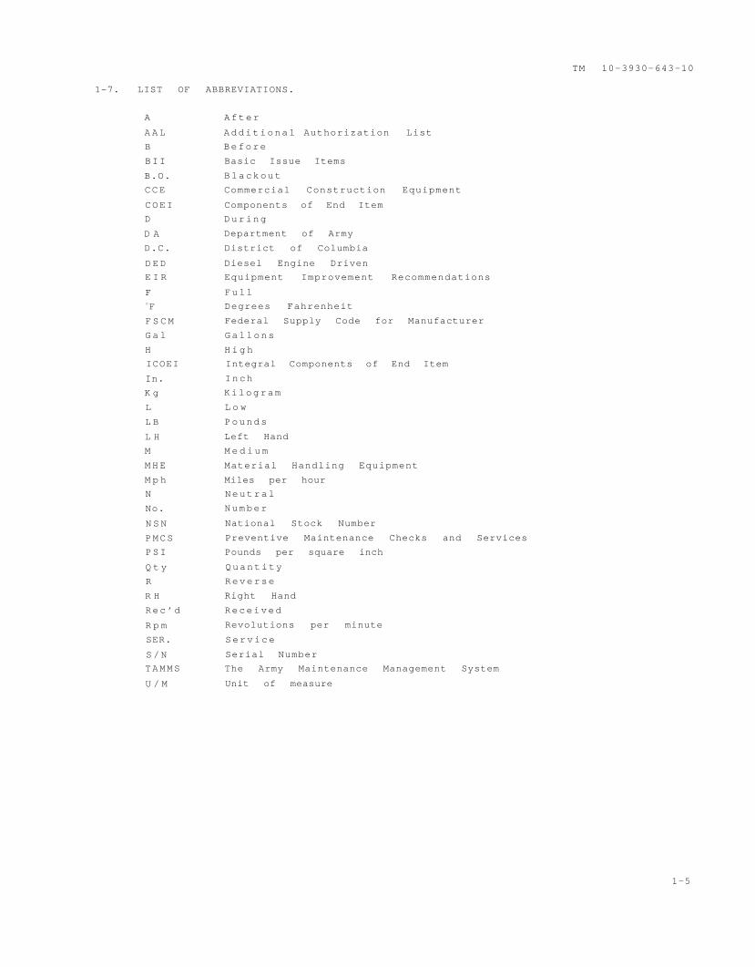
List of Abbreviations
EQUIPMENT DESCRIPTION AND DATA
Equipment Characteristics, Capabilities
and Features
Location and Description of Major
Components
Differences Between Models
Equipment Data
PRINCIPLES OF OPERATION
Engine
Fuel System
Exhaust System
Cooling System
Electrical System
Transmission Controls
Air System
Brakes
Steering
Hydraulic System and Implements
Paragraph
1-1
1-2
1-3
1-4
1-5
1-6
1-7
1 - 8
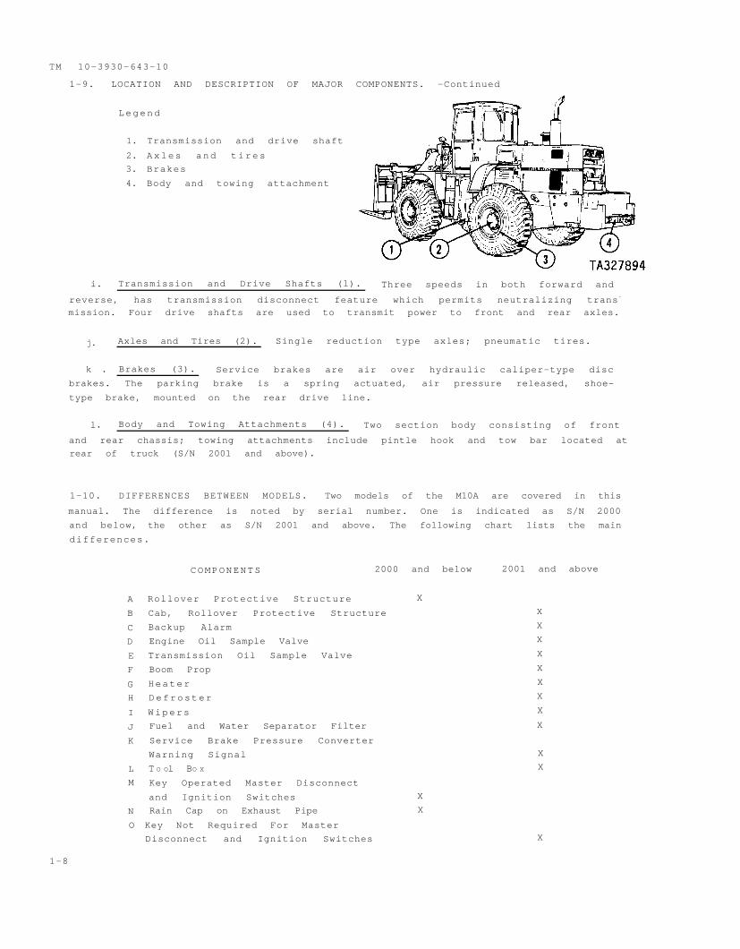
1-9
1-10
1-11
1-12
1-13
1-14
1-15
1-16
1-17
1-18
1-19
1-20
1-21
P a g e
1-1
1-1
1-1
1-3
1-3
1-3
1-3
1-4
1-4
1-5
1-6
1-7
1-8
1-13
1-14
1-14
1-15
1-15
1-16
1-19
1-20
1-21
1-22
1-22
i
APPROVED FOR PUBLIC RELEASE. DISTRIBUTION lS UNLlMlTED.
* This manual supersedes the Operator’s portion of TM 10-3930-643-14&P, dated 30 Nov 81 with all
changes.
TM 10-3930-643-10
TABLE OF CONTENTS-Continued
CHAPTER 2.
Section I
Section II
Section III
Section IV
OPERATING INSTRUCTIONs~
CHAPTER OVERVIEW
INDEX
DESCRIPTION AND USE OF OPERATOR’S
CONTROLS AND INDICATORS
Operator’s Compartment
Instrument Console
Steering Wheel and Hand Throttle
Control
Service Brakes, Brake and Transmission
Disconnect Pedal and Accelerator
Transmission Gear Range Lever,
Transmission Direction Lever, and
Transmission Safety Lock
Lift Control Lever, Tilt Control
Lever, and Fork Control Lock
Sideshift, Oscillate, and Fork
Positioner Lever
Mode Selector Switch
Windows
Heater Controls
Defroster Fan Speed Switches
Windshield Wiper Controls
Rear Window Wiper Controls
Air Cleaner Service Indicator
Electrical System Master Disconnect
Switch
Coolant Level Sight Gage
Engine Oil Dipstick
PREVENTIVE MAINTENANCE CHECKS AND SERVICES
Preventive Maintenance Checks and
Services
OPERATION UNDER USUAL CONDITIONS
Initial Adjustments, Daily Checks,
and Self Test
Operating Procedures
Preparation For Movement
Operating Instructions on Decals and
Instruction Plates
OPERATION UNDER UNUSUAL CONDITIONS
Operation in
Operation in
Operation in
Operation in
Operation in
Fording
Unusual Weather
Dusty or Sandy Areas
Saltwater Areas
High Altitudes
Snow
Paragraph
2-1
2-2
2-3
2-4
2 - 5
2-6
2-7
2-8
2-9
2-10
2-11
2-12
2-13
2-14
2-15
2-16
2-17
2-18
2-19
2-20
2-21
2-22
2-23
2-24
2-25
2-26
2-27
2-28
P a g e
2-1
2-1
2-1
2 - 3
2-4
2-8
2-9
2-9
2-10
2-10
2-11
2-11
2-12
2-12
2-12
2-12
2-13
2-13
2-13
2-13
2-14
2-31
2-32
2-44
2-45
2-54
2-57
2-57
2-57
2-57
2-57
ii
TM 10-3930-643-10
TABLES OF CONTENTS-Continued
CHAPTER 3.
Section I
Section II
Section III
APPENDIX A
APPENDIX B
APPENDIX C
APPENDIX D
OPERATOR/CREW MAINTENANCE INSTRUCTIONS
CHAPTER OVERVIEW
INDEX
L U B R I C A T I O N
Lubrication Instructions
Lubrication Information
OPERATOR/CREW TROUBLESHOOTING
PROCEDURES
Troubleshooting Information
Troubleshooting Symptom Index
Troubleshooting Procedures
MAINTENANCE PROCEDURES
Operator Maintenance
Paragraph
REFERENCES
COMPONENTS OF END ITEM LIST AND BASIC ISSUE
ITEMS LIST
ADDITIONAL AUTHORIZATION LIST
EXPENDABLE/DURABLE SUPPLIES AND MATERIALS LIST
SUBJECT INDEX
ERROR REPORTING FORM (DA-2028-2)
METRIC CONVERSION TABLE
3-1
3-2
3-3
3-4
3-5
3-6
P a g e
3-1
3-1
3-1
3-1
3-2
3-2
3-3
3-4
3-12
A - 1
B-1
C-1
D-1
INDEX 1
iii
TM 10-3930-643-10
MHE 236 FORKLIFT TRUCK
(Right Front View (S/N 2000 and below) (Right Front View (S/N 2001 and above)
(Left Rear View (S/N 2000 and below) (Left Rear View (S/N 2001 and above)
TA327892
1-0
TM 10-3930-643-10
CHAPTER 1
INTRODUCTION
CHAPTER OVERVIEW
The purpose of this chapter is to acquaint you with the maintenance forms,
records, and reports that you must maintain for the forklift truck, to
familiarize you with the purpose and capabilities of the forklift truck and to
give you a brief description of the different systems and components of the
forklift truck.
HOW TO USE THIS MANUAL
This manual is designed to help you operate and maintain the M10A Forklift. It
is divided into chapters, sections, and appendices. Chapter 1 contains infor-
mation concerning the vehicle, its characteristics, systems, and components.
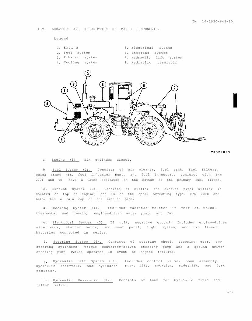
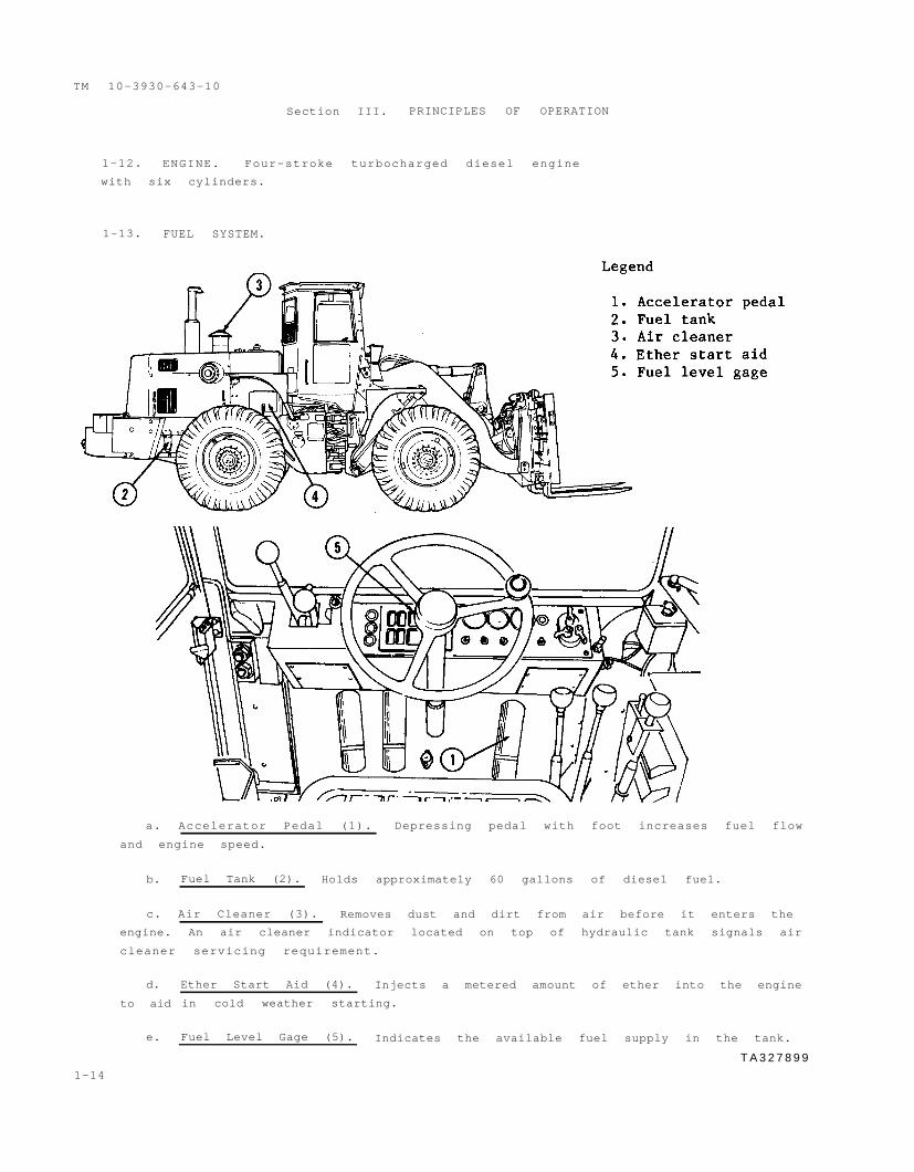
a. Accelerator Pedal (1). Depressing pedal with foot increases fuel flow
and engine speed.
b. Fuel Tank (2). Holds approximately 60 gallons of diesel fuel.
c. Air Cleaner (3). Removes dust and dirt from air before it enters the
engine. An air cleaner indicator located on top of hydraulic tank signals air
cleaner servicing requirement.
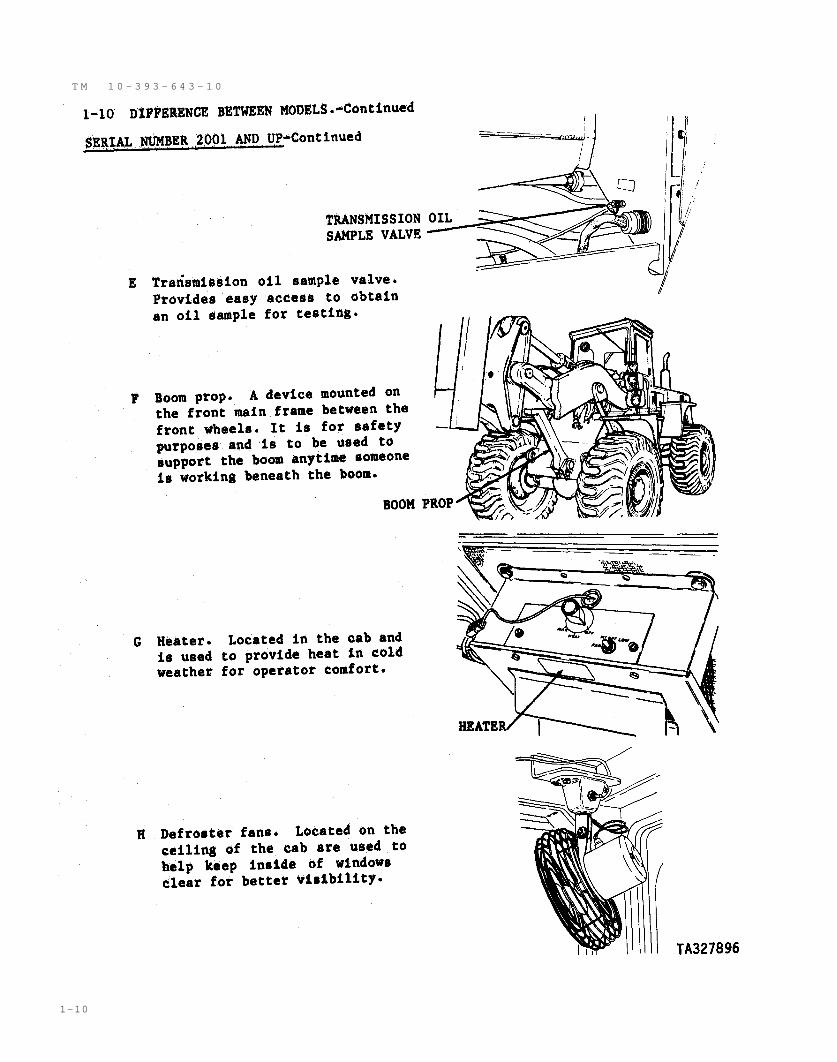
d.
to aid
e.
1-14
Ether Start Aid (4). Injects a metered amount of ether into the engine
in cold weather starting.
Fuel Level Gage (5). Indicates the available fuel supply in the tank.
T A 3 2 7 8 9 9
TM 10-3930-643-10
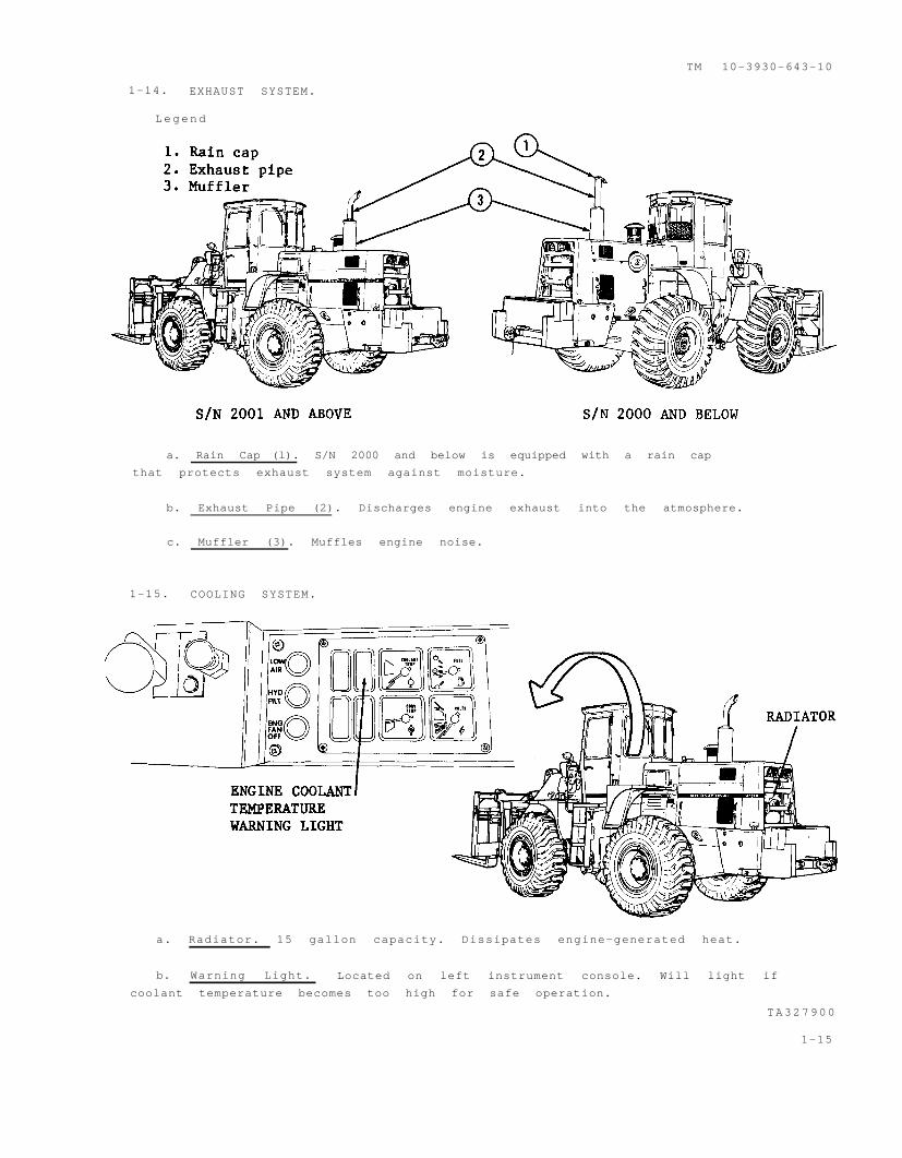
1-14. EXHAUST SYSTEM.
Legend
a. Rain Cap (l). S/N 2000 and below is equipped with a rain cap
that protects exhaust system against moisture.
b. Exhaust Pipe (2). Discharges engine exhaust into the atmosphere.
c. Muffler (3). Muffles engine noise.
1-15. COOLING SYSTEM.
a. Radiator. 15 gallon capacity. Dissipates engine-generated heat.
b. Warning Light. Located on left instrument console. Will light if
coolant temperature becomes too high for safe operation.
TA327900
1-15
TM 10-3930-643-10
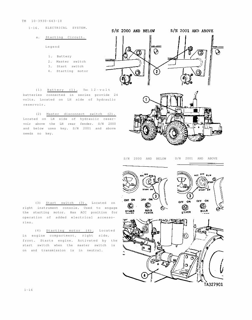
1-16. ELECTRICAL SYSTEM.
a. Starting Circuit.
Legend
1. Battery
2. Master switch
3. Start switch
4. Starting motor
(1) Battery (1). TWO 1 2 - v o l t
batteries connected in series provide 24
volts. Located on LH side of hydraulic
reservoir.
(2) Master disconnect switch (2).
Located on LH side of hydraulic reser-
voir above the LH rear fender. S/N 2000
and below uses key. S/N 2001 and above
needs no key.
S/N 2000 AND BELOW S/N 2001 AND ABOVE
(3) Start switch (3). Located on
right instrument console. Used to engage
the starting motor. Has ACC position for
operation of added electrical accesso-
ries.
(4) Starting motor (4). Located
in engine compartment, right side,
front. Starts engine. Activated by the
start switch when the master switch is
on and transmission is in neutral.
1-16
1-16. ELECTRICAL SYSTEM.-Continued
TM 10-3930-643-10
(1) Alternator (l). Maintains the voltage charge in the battery.
(2) Voltmeter (2). Located on left instrument console. With starting
switch on RUN, pointer registers in low green area and indicates condition of
batteries. With engine running and starting switch on RUN, pointer registers in
high green area and indicates if the alternator is producing electric current.
(1) Headlights (1). Two sealed beam type. Lights (1) provide low beam,
controlled by the vehicle light switch assembly.
(2) Front service lights (2). Two sealed beam type for normal forward
illumination. Controlled by the front service light switch.
(3) Rear service lights (3). Two sealed beam type for rear illumination
controlled by the rear service light switch.
(4) Front blackout light (4). Provides forward blackout illumination
during tactical operations.T A 3 2 7 9 0 2
1-17
TM 10-3930-643-10
1-16. ELECTRICAL SYSTEM.-Continued
c. Lighting Circuit.-Continued
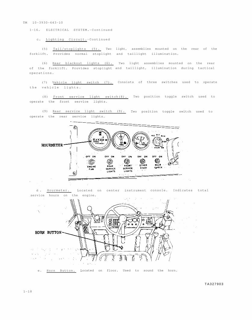
(5) Tail/stoplights (5). Two light, assemblies mounted on the rear of the
forklift. Provides normal stoplight and taillight illumination.
(6) Rear blackout lights (6).
of the forklift. Provides stoplight
operations.
(7) Vehicle light switch (7).
t h e v e h i c l e l i g h t s .
Two light assemblies mounted on the rear
and taillight, illumination during tactical
Consists of three switches used to operate
(8) Front service light switch(8). Two position toggle switch used to
operate the front service lights.
(9) Rear service light switch (9). Two position toggle switch used to
operate the rear service lights.
d . Hourmeter. Located on center instrument
service hours on the engine.
console. Indicates total
e. Horn Button. .Located on floor. Used to sound the horn.
T A 3 2 7 9 0 3
1-18
TM 10-3930-643-10
1-16. ELECTRICAL SYSTEM.-Continued
f. Backup Alarm. Models S/N 2001 and above.
(1) Backup alarm switch. When the
transmission directional lever is moved
to reverse, the backup alarm will sound.
(2) Alarm. Located center grille,
rear of machine. Sounds to warn person-
nel the vehicle is backing up. A HIGH-
LOW switch is located on the backside of
the alarm. This switch should be left
in the HIGH position.
1-17. TRANSMISSION CONTROLS.
a. Transmission Gear Range Lever
(l). Located to the left of the steer-
ing wheel on the dashboard. Selects any
of the three gear ranges.
b. Transmission Direction Lever (2).
Located to the left of the steering
wheel on the dashboard. Selects machine
direction or neutral position.
c. Transmission Control Lever Safety
Lock (3). Located in between trans-
mission direction lever and parking/
emergency brake. Locks transmission in
neutral to prevent accidental movement.
Transmission Disconnect Pedal
(4). Located on the floor. Acts as a
brake and also stops clutch pressure In
the transmission.
Legend
1. Transmission gear range lever
2. Transmission direction lever
3. Transmission direction lever
safety lock
4. Transmission disconnect pedal
T A 3 2 7 9 0 4
1-19
1-18. AIR SYSTEM.
TM 10-3930-643-10
d.
in the
Low Air Pressure Indicator (4). Lights and alarm sounds when pressure
tanks is below normal, safe operating level (60 psi).
T A 3 2 7 9 0 5
1-20
1-19. BRAKES .
Legend
TM 10-3930-643-10
1.
2.
3.
4.
5.
6.
7.
8.
Brake pedal
Service brake
(S/N 2001 and
clusters (S/N
pressure converters
above)/power
2000 and below)
Brake pads and discs
Service brake warning light
Pressure converter warning alarm
Parking/emergency brake control
Parking brake warning light
Parking brake warning alarm
a. Service Brakes. An air over hydraulic disc brake system used to
and stop the vehicle.
(1) Brake pedal (1). Controls the brake treadle valve to direct
the pressure converters.
control
air to
(2) Service brake pressure converter (2). Converts air pressure to
hydraulic pressure to engage the brakes.
(3) Brake pads and discs (3). Controlled by the pressure converter, the
pads press against the discs for braking action.
(4) Service brake warning light (4). Will flash off and on, if brake
hydraulic pressure drops to low for positive braking.
(5) pressure converter warning alarm (5). Alarm will sound when
hydraulic pressure drops to low for positive braking.
b. Parking/Emergency Brake. A drum type, spring engaged, air disengaged
brake used for parking and emergency stopping situations.
(1) Parking/emergency brake control (6). Used to set or release parking/
emergency brake. Directs air to parking brake air cylinder.
T A 3 2 7 9 0 6
1-21
1-22
T M 10-3930-643-10
1-19. BRAKES.-Continued
(2) Parking brake warning light (7).
is applied.
(3) Parking brake warning horn (8).
applied.
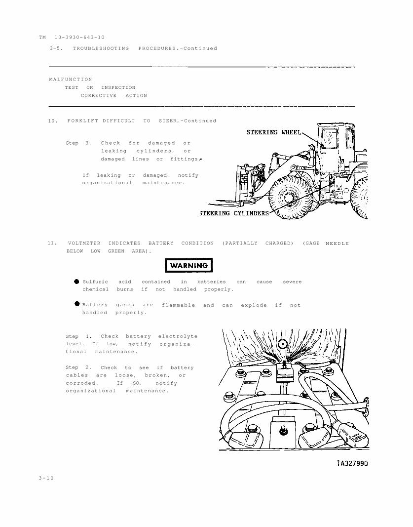
1-20. STEERING. Steering is accomplished
hydraulics.
Will come on when the parking brake
Will sound when the parking brake is
by articulation through the use of
a. Steering Wheel (l). Used to change direction of vehicle movement.
Controls steering cylinders for articulation.
b. Steering Cylinders (2). One cylinder, on each side of the forklift.
TM 10-3930-643-10
1-21. HYDRAULIC SYSTEM AND IMPLEMENTS.-Continued.
a. Reservoir (1). Provides hydraulic fluid supply for hydraulic system
and steering. 14.5 gallon capacity.
b. Fork Carriage Cylinders and Controls.
(1) Lift control lever (2). Permits fork carriage to be raised, lowered,
or held in position.
(2) Lift cylinder (3). Raising and lowering of the fork carriage is
accomplished through the use of two hydraulic cylinders.
(3) Tilt control lever (4). Permits fork carriage to be tilted back,
tilted forward, or held in position.
(4) Tilt cylinder (5). Tilting of the fork carriage is accomplished
through the use of one hydraulic cylinder.
(5) Sideshift, oscillate, and fork positioner lever (6). Together with
the attached mode selector switch (7) permits the following lever positions:
. Forks apart
. Hold
. Forks together
. Oscillate left side down
. Hold
. Oscillate right side down
. Side shift left
. Hold
. Side shift right
(6) Sideshift cylinder (8).
is accomplished through the use of
Left and right shifting of the fork carriage
one cylinder.
(7) Oscillate cylinder (9). Lowering of the left or right side of the
fork carriage is accomplished through the use of one cylinder.
(8) Fork positioner cylinders (10). Spreading or closing of the forks is
accomplished through the use of two cylinders.
(9) Fork carriage (11). Used to hold material while loading/unloading,
or transporting.
(10) Fork control lock (12). Locks fork to prevent undesirable fork
movement during operation.
1-23 (1-24 blank)
TM 10-3930-643-10
CHAPTER 2
OPERATING INSTRUCTIONS
CHAPTER OVERVIEW
This chapter describes the operation of vehicle controls, switches, and
indicators. It includes authorized Preventive Maintenance Checks and Services
(PMCS) and step-by-step vehicle operating procedures.
INDEX
Section Title
I DESCRIPTION AND USE OF OPERATOR’S CONTROLS
AND INDICATORS
Operator’s Compartment
Instrument Console
Steering Wheel and Hand Throttle Control
Service Brakes, Brake and Transmission
Disconnect Pedal and Accelerator
Transmission Gear Range Lever, Transmission
Direction Lever, and Transmission Safety Lock
Lift Control Lever, Tilt Control Lever, and
Fork Control Lock
Sideshift, Oscillate, Fork Positioner Lever
Mode Selector Switch
Windows
Heater Controls
Defroster Fan Switches
Windshield Wiper Control
Rear Window Wiper Controls
Air Cleaner Service Indicator
Electrical System Master Disconnect Switch
Coolant Level Sight Gage
Engine Oil Dipstick
II OPERATOR/CREW PREVENTIVE MAINTENANCE CHECKS
AND SERVICES
Preventive Maintenance Checks and Services
Paragraph Page
2-1
2-2
2-3
2-4
2-5
2-6
2-7
2-8
2-9
2-10
2-11
2-12
2-13
2-14
2-15
2-16
2-17
2-3
2-4
2-8
2-9
2-9
2-10
2-10
2-11
2-11
2-12
2-12
2-12
2-12
2-13
2-13
2-13
2-13
2-18 2-14
2-1
TM 10-3930-643-10
INDEX-Continued
Section Title Paragraph Page
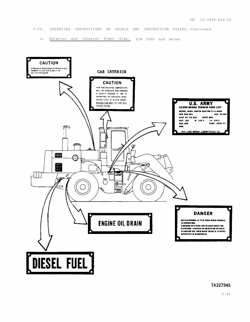
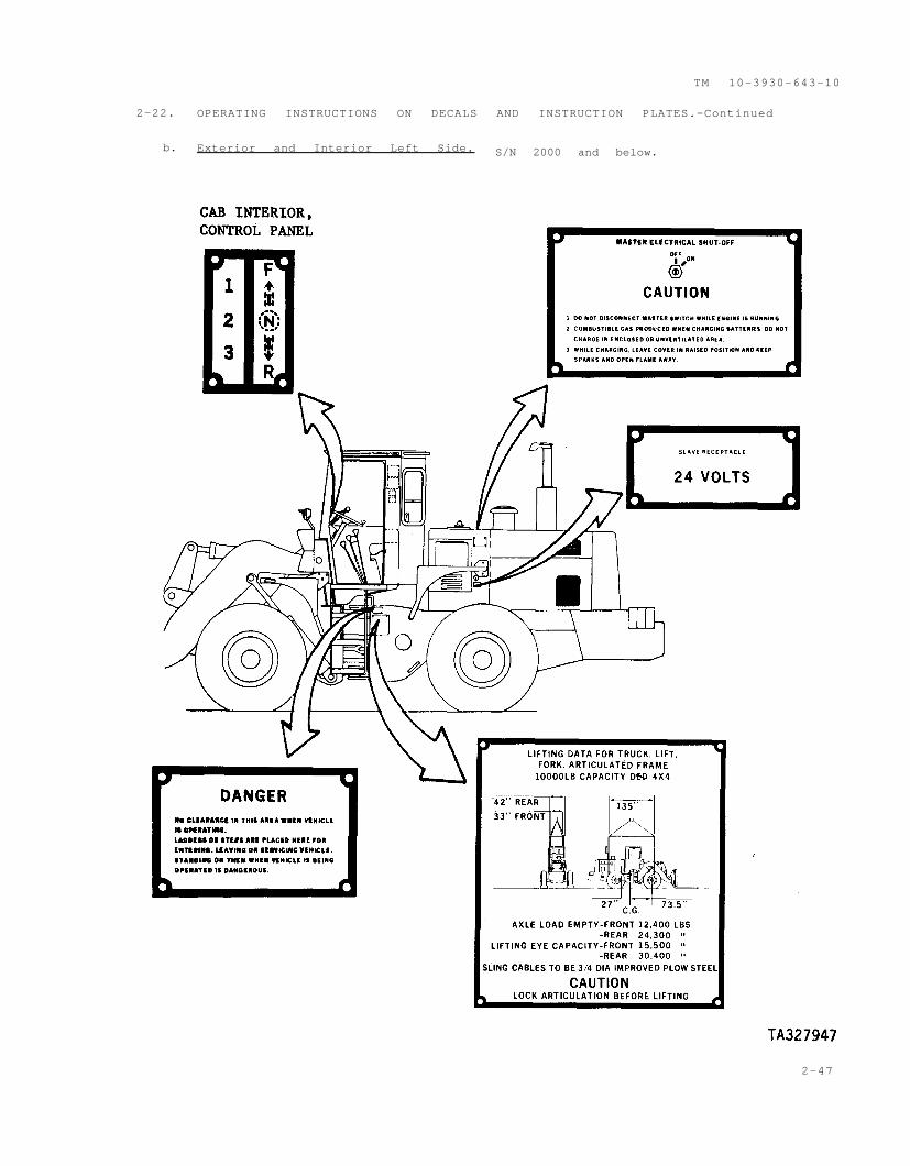
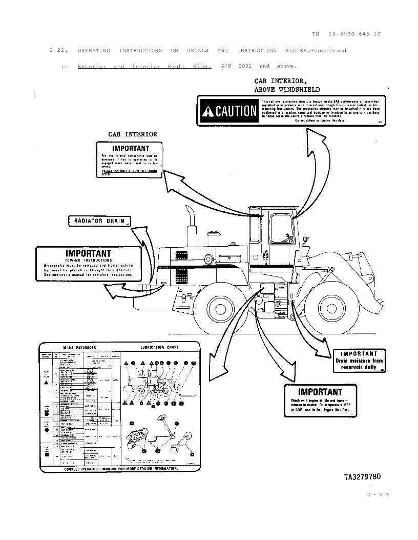
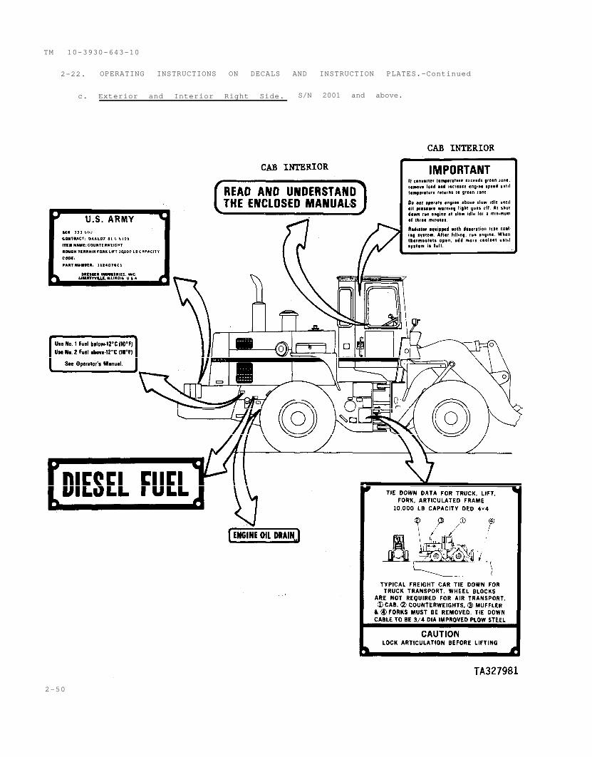
III OPERATION UNDER USUAL CONDITIONSInitial Adjustments, Daily Checks, and Self Test 2-19 2-31Operating Procedures 2-20 2-32Preparation for Movement 2-21 2-44Operating Instructions on Decals and Instruction
Plates 2-22 2-45
IV OPERATION UNDER UNUSUAL CONDITIONSOperation in Unusual Weather 2-23 2-54Operation in Dusty or Sandy Areas 2-24 2-57Operation in Saltwater Areas 2-25 2-57Operation at High Altitudes 2-26 2-57Operation in Snow 2-27 2-57Fording 2-28 2-57
2-2
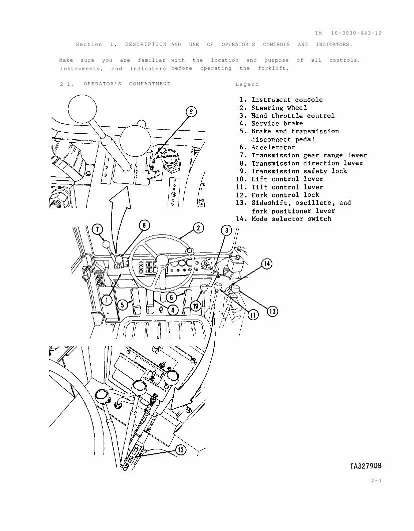
Section 1. DESCRIPTION
Make sure you are familiar
instruments, and indicators
2-1. OPERATOR’S COMPARTMENT
TM 10-3930-643-10
AND USE OF OPERATOR’S CONTROLS AND INDICATORS.
with the location and purpose of all controls,
before operating the forklift.
Legend
2-3
TM 10-3930-643-10
2-2. INSTRUMENT
Legend
Hydraulic
Low air l
a.
1.
2.
3.
4.
5.
6.
7.
8.
9.
Engine
CONSOLE.
oil pressure warning light
Parking brake warning light
Engine coolant temperature warning light
Service brake warning light
Torque converter temperature warning light
Ground driven steering warning light
Engine fan OFF light
I n d i c a t o r s .
(1) Engine oil pressure warning light (1). When lighted, the engine oil
pressure is below normal.
(2) Parking brake warning light (2). This light will come on when the
parking brake is applied and the starting switch is on. The parking brake horn
will also sound.
(3) Engine coolant temperature warning light (3). When lighted, the
engine coolant temperature is too high for safe operation.
(4) Service brake warning light (4). This light will flash on and off if
the brake hydraulic pressure is too low for positive braking.
(5) Torque converter temperature warning light (5). When lighted, the
torque converter oil temperature is too high for safe operation.
(6) Ground driven steering warning light (6). When lighted, the ground
driven steering is operational, and the vehicle should be safely parked as soon
as possible.
(7) Engine fan OFF light (7). When lighted,
operating.
(8) Hydraulic filter warning light (8). This
flow through the reservoir filter is restricted due
filter.
(9) Low air light (9). When lighted, the air
below safe operating level.
2-4
the engine fan is not
light will come on if oil
to cold oil or a clogged
pressure in the system is
TM 10-3930-643-10
2-2. INSTRUMENT CONSOLE.-Continued
b. Gages.
total service hours on the engine. Use
it to determine service intervals.
(4) Air pressure gage (4). Indicates the air pressure available in the
air tank. This gage must register in the RUN range for safe machine operation.
(5) Engine oil pressure gage (5). Indicates the
lubricating oil circulating through the engine. This gage
RUN range when operating at full load speeds.
pressure of the
must register in the
(6) Voltmeter (6). Indicates the condition of the battery when pointer
is in the low green area. Indicates whether the alternator is charging when
pointer is in the high green area.
(7) Torque converter temperature gage (7). Indicates the temperature of
the fluid in the torque converter. This gage should register in the green range
during operation.
T A 3 2 7 9 1 0
2-5
WARNING
TM 10-3930-643-10
2-2. INSTRUMENT CONSOLE.-Continued
Legend
1. Parking/emergency brake
control knob
2. Starting switch
3. Light switch
4. Bulb check switch
5. Ether start switch
6. Front service light switch
7. Rear service light switch
8. Engine fan switch
c. Switches.
(1) Parking/emergency brake control knob (1).
When the emergency brake is applied, be prepared for an
abrupt stop.
(a) Engage. Pull the knob to set the parking brake. The parking brake
should be set any time the operator leaves the operator compartment. While the
parking brake is engaged, the parking brake warning light will be lit and the
warning horn will sound , until the brake is released or the starting switch is
shut off.
Pull the knob to apply the
the machine. The machine
applied.
(b) Release. Push
not release until there iS _
emergency brake, if the service brakes fail to stop
will stop abruptly when the emergency brake is
the button in to release the brakes. The brakes will
ample air pressure in the system.
(2) Starting switch (2).
Legend
1. ACC
2. OFF
3. RUN
4. START
(a)
accessories
(b)
operated.
The ACC position (1). Allows the use of added electrical
without the engine running.
OFF position (2). Use this position when the machine is not being
RUN position (3). Switch will return to this position automati-(c)
cally when released from the START position. Will remain in this position.
(d) START position (4). Turn the switch to the far right to crank the
engine. Engine will not start unless the master disconnect switch is on.
2-6T A 3 2 7 9 1 1
2-2. INSTRUMENT CONSOLE.-Continued
(3) Light switch assembly (3).
(a) Main switch (1). Five
position switch. Mechanical lock lever
must be held in the UNLOCK position
before moving the main switch lever to
any position.
NOTE
Master disconnect switch must be in the ON position for
the vehicle light switch assembly to operate.
1 BLACKOUT DRIVE position (2). Blackout tail lights and blackout
driving light lighted. Blackout stop light will light when brakes are applied.
2 BLACKOUT marker position (3). Blackout tail lamps lighted and
stop lamp will light when brakes are applied.
3 OFF position (4). All lights off. Auxiliary switch(es) disabled.
4 STOP LIGHT position (5). Service brake lights will light when
brake is applied.
5 SERVICE DRIVE position (6). Service tail light lighted. Brake
lights will light when brakes are applied. Front headlights lighted. Front and
rear service lights will light when front and rear service light switches are
activated.
N O T E
Main switch must be in any position other than OFF for
auxiliary switch to operate.
(b) Auxiliary switch (7). Four position switch.
1 PANEL BRIGHT position (8). Instrument panel lamps brightly
lighted.
2 PANEL DIM position (9). Instrument panel lamps dimly lighted.
3 PANEL OFF position (10). Instrument panel lamps off. Service or
blackout tail lamps off.
4 PARKING LIGHT position (11). Instrument panel lamps dimly lighted,
Service tail lamps lighted (main switch in SERVICE DRIVE position). Blackout
tail lamps lighted (main switch in BLACKOUT DRIVE position or BLACKOUT MARKER
position).
2-7
2-3
TM 10-3930-643-10
2-2. INSTRUMENT CONSOLE.-Continued
(c) Mechanical switch (12). Spring loaded, two position switch.
1 LOCK position (unmarked). Prevents movement of main switch (A).
2 UNLOCK position. Enables movement of main switch (A). Hold lever
in UNLOCK position and move main switch (3) to desired position.
(4) Bulb check switch (4). Use to check operation of instrument panel
lights. Switch will return to OFF position when released. The oil pressure,
ground driven steering, and low air lights are not checked by this switch.
(5) Ether start switch (5). Used in cold weather only to inject starting
fluid (ether) into the intake manifold to aid in starting the engine. Push the
button only while cranking the engine to inject a metered amount of starting
fluid.
(6) Front service light switch (6). Controls the front service lights.
Light switch (3) must be in the SERVICE DRIVE position before using this
switch.
(7) Rear service light switch (7). Controls the rear service lights.
Light switch (3) must be in the service drive position before using this
switch.
Never operate forklift without the engine fan switch on
except when water fording. Failure to operate fan will
result in engine overheating and damage to engine.
Engage or disengage engine fan
operating at low idle.
(8) Engine fan switch (8). Controls
only when engine is
the engine fan. Engine fan switch is
always ON except when fording because water will enter fan sweep.
2-8
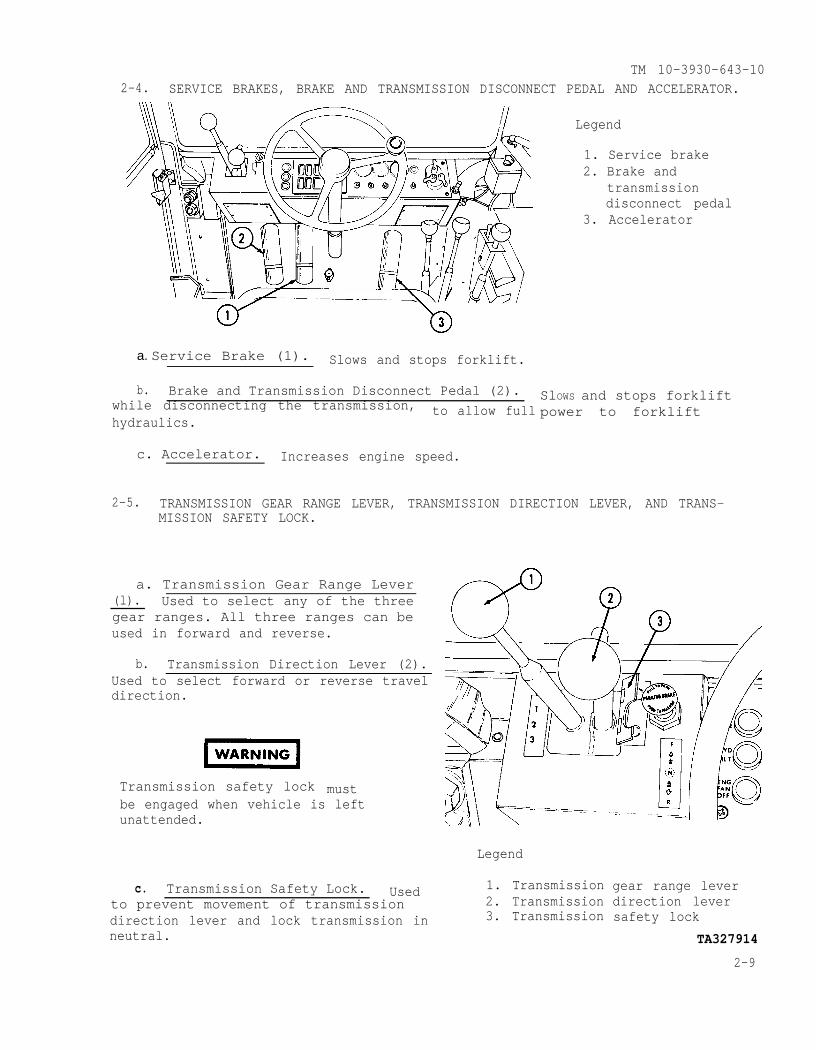
TM 10-3930-643-102-4. SERVICE BRAKES, BRAKE AND TRANSMISSION DISCONNECT PEDAL AND ACCELERATOR.
a. Service Brake (1). Slows and stops forklift.
b. Brake and Transmission Disconnect Pedal (2).while disconnecting the transmission, to allow fullhydraulics.
Legend
1. Service brake2. Brake and
transmissiondisconnect pedal
3. Accelerator
SlOWS and stops forkliftpower to forklift
c. Accelerator. Increases engine speed.
2-5. TRANSMISSION GEAR RANGE LEVER, TRANSMISSION DIRECTION LEVER, AND TRANS-MISSION SAFETY LOCK.
a. Transmission Gear Range Lever(l). Used to select any of the threegear ranges. All three ranges can beused in forward and reverse.
b. Transmission Direction Lever (2).Used to select forward or reverse traveldirection.
mustTransmission safety lockbe engaged when vehicle is leftunattended.
c. Transmission Safety Lock. Usedto prevent movement of transmissiondirection lever and lock transmission inneutral.
Legend
1. Transmission2. Transmission3. Transmission
gear range leverdirection leversafety lock
TA327914
2-9
T M 1 0 - 3 9 3 0 - 6 4 3 - 1 0
2 - 6 . LIFT CONTROL LEVER, TILT CONTROL LEVER, AND FORK CONTROL LOCK.
Legend
1. Lift control lever2. Tilt control lever3. Fork control lock
a. Lift Control Lever (1). Controls the raising and lowering of the forksby moving back to raise the forks, and moving forward to lower the forks. Thelever will always return to hold when releasedattained position.
, and the forks will stay in the
b. Tilt Control Lever (2). Controls the tilting of the forks.
c. Fork Control Lock (3). Moves over control levers to lock in neutral.
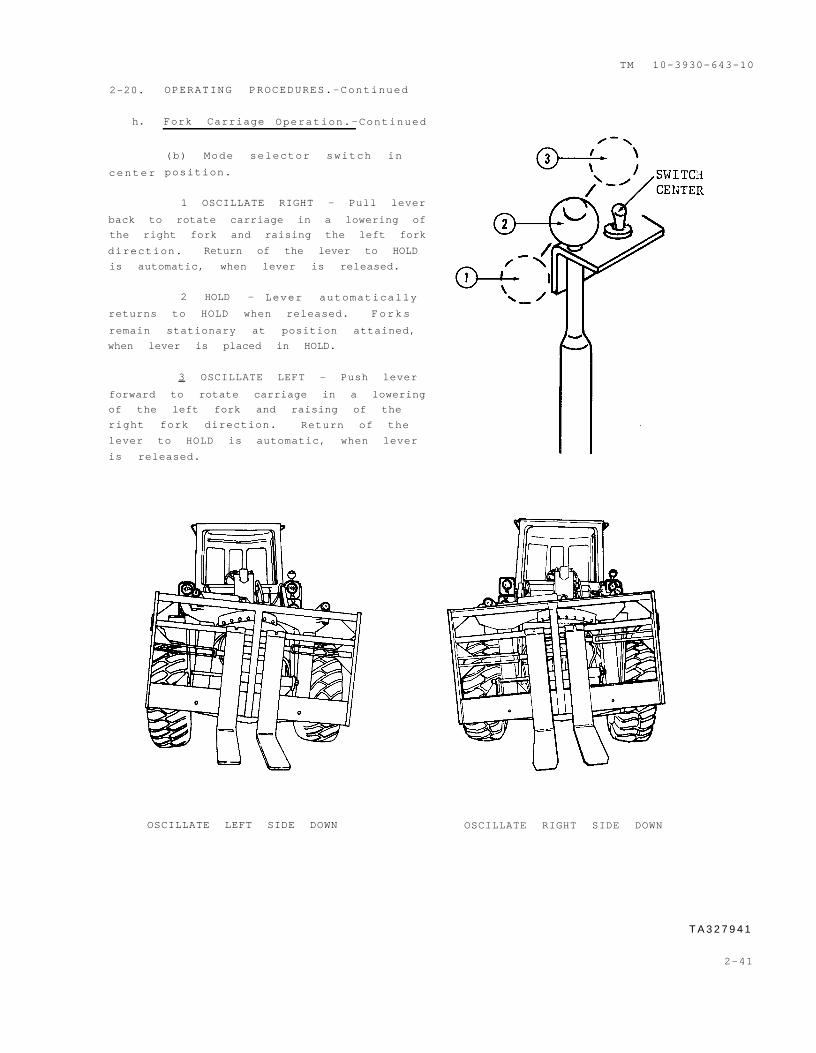
2 - 7 . SIDESHIFT, OSCILLATE, AND FORK POSITIONER LEVER (l). Controls the three
following movements of the forks depending on the selection of the mode switch.
a. Sideshift. Movement of the leverlever in this mode will result in ashift of the entire fork carriage,either to the right or the left. Forwardwill shift to the left, and back willshift to the right.
b. Oscillate. Movement of the leverin this mode will result in a rockingmovement of the fork carriage witheither the right or left fork beinglower than the other. Forward will lowerthe left fork and back will lower theright fork.
c. Fork Positioner. Movement of the lever in thismovement of the forks, either away from each other, orForward will move the forks away from each other, back will move the forkscloser to each other.
2 - 1 0TA327915
Legend
1. Three movement lever2. Mode selector switch
mode will result in acloser to each other.
2-8. MODE SELECTOR SWITCH (2). Selects one
a. Rear Position. Selects the sideshift
TM 10-3930-643-10
of three modes of fork operation.
mode of operation.
b. Middle Position. Selects the oscillation mode of operation.
c. Forward Position. Selects the lateral movement mode of operation. To
attain this switch position, the toggle lever cap must be pulled up and pushed
foreward at the same time
2-9. WINDOWS. Serial number 2001 and
above. May be opened to provide
ventilation in cab.
a. Left Hand Side Window. Secures
with window latch. Opens out to rear.
Secures in open position with window
retainer on outside of cab. W i n d o w
retainer releases with lever at left
rear of cab.
b. Right Hand Side Window. Secures
with window latch (1). Opens out to
rear. Secures in open position by
tightening knob (3) on window control
rod (2).
Legend
1. Window latch
2. Window control rod
3. Knob
2-11
10-3930-643-10
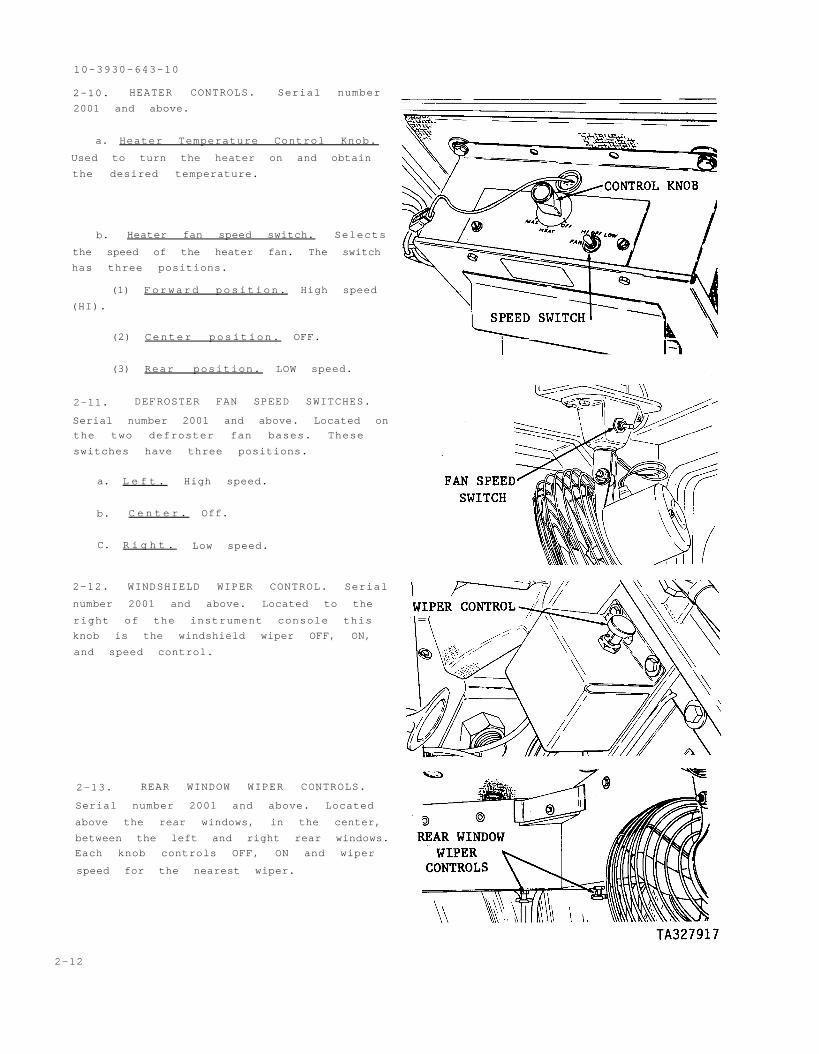
2-10. HEATER CONTROLS. Serial number
2001 and above.
a. Heater Temperature Control Knob.
Used to turn the heater on and obtain
the desired temperature.
b. Heater fan speed switch. Selects
the speed of the heater fan. The switch
has three positions.
(1) Forward position. High speed
(HI).
(2) Center position. OFF.
(3) Rear position. LOW speed.
2-11. DEFROSTER FAN SPEED SWITCHES.
Serial number 2001 and above. Located on
the two defroster fan bases. These
switches have three positions.
a. L e f t . High speed.
b. C e n t e r . Off.
C. R i g h t . Low speed.
2-12. WINDSHIELD WIPER CONTROL. Serial
number 2001 and above. Located to the
right of the instrument console this
knob is the windshield wiper OFF, ON,
and speed control.
2-13. REAR WINDOW WIPER CONTROLS.
Serial number 2001 and above. Located
above the rear windows, in the center,
between the left and right rear windows.
Each knob controls OFF, ON and wiper
speed for the nearest wiper.
2-12
CAUTION
2-14. AIR CLEANER SERVICE INDICATOR.
Located on top of the reservoir to the
left of the reservoir fill cap. It
determines when the air filter is to be
TM 10-39-30-64-10
serviced.
Electrical system will be damaged if master disconnect
switch is left OFF with engine running. The batteries
will discharge if master disconnect switch is left ON
with engine not running.
2-15. ELECTRICAL SYSTEM MASTER
DISCONNECT SWITCH. Located on the left
side of the hydraulic reservoir next to
the battery box. When turned to OFF will
deactivate the forklift’s entire
electric system. If left ON when the
forklift is not running, the batteries
will discharge. If left OFF with engine
running, the electrical system will be
damaged.
2-16. COOLANT LEVEL SIGHT GAGE.
Located at the top rear of the radiator,
coolant is viewed through the gage. The
coolant level must be visable in the
gage.
2-13
2-17. ENGINE OIL DIPSTICK. Located on the right side of the engine.
TM 10-3930-643-10
Section II. OPERATOR/CREW
PREVENTIVE MAINTENANCE CHECKS AND SERVICES (PMCS)
2-18. PREVENTIVE MAINTENANCE CHECKS AND SERVICES.
GENERAL
Your Preventive Mintenance Checks and Services Table lists the inspections and
care of your equipment required to keep it in good operating condition.
OPERATOR/CREW PREVENTIVE MAINTENANCE CHECKS AND SERVICES
1. The number column of your PMCS is the source for the number used on the TM
Number Column on DA Form 2407.
2. The interval column of your PMCS Table tells you when to do a certain check
or service.
a. Before you operate. Perform your before (B) PMCS. Always keep in mind
the WARNINGS and CAUTIONS.
b. While you operate. Perform your during (D) PMCS. Always keep in mind
the WARNINGS and CAUTIONS.
c. After you operate. Be sure to perform your after (A) PMCS.
d. Once a week. Perform your weekly (W) PMCS. Always keep in mind the
WARNINGS and CAUTIONS.
3. The procedure column of your PMCS Table tells you how to do the required
checks and services. Carefully follow these instructions. If you do not have
the tools, or if the procedure tells you to, have organizational maintenance do
the work.
4. If your equipment does not perform as required
ing section in this manual for possible problems.
, refer to the troubleshoot-
Report any malfunctions or
failures on the proper DA Form 2404 or refer to DA Pamphlet 738-750.
NOTE
The terms ready/available and mission capable refer to
the same status: Equipment is on hand and is able to
perform its combat missions (see DA Pamphlet 738-750).
5. Equipment is NOT READY/AVAILABLE IF: column. This column tells you when
and why your equipment cannot be used.
6. Always do your PMCS in the same order so it gets to be a habit. Once
you’ve had some practice, you will spot anything wrong in a hurry.
7. When you do your PMCS, take along a rag or two.
2-14
WARNING
TM 10-3930-643-10
2-18. PREVENTIVE MAINTENANCE CHECKS AND SERVICES.-Continued
8. While performing PMCS, observe WARNINGS and CAUTIONS preceding those oper-
ations which could endanger your safety or result in damage to the equipment.
Dry cleaning solvent, P-D-680, is toxic and flammable.
Wear protective goggles and gloves and use only in well-
ventilated area. Avoid allowing solvent to contact
skin, eyes, and clothes, and don’t breathe vapors. Do
not use near open flame or excessive heat. If you
become dizzy while using cleaning solvent, get fresh air
immediately and get medical aid. If solvent comes in
contact with skin or clothing, wash with water. If
solvent gets in your eyes, flush eyes with water and get
medical aid immediately. Flash point of solvent is
100°-1380F (38°-590c).
a. Keep it clean. Dirt, grease, oil and debris only get in the way and may
cover up a serious problem. Clean as you work and as needed. Use dry cleaning
solvent (P-D-680) to clean metal surfaces. Use soap and water when you clean
rubber or plastic material.
b. Bolts, nuts, and screws. Check that they are not loose, missing, bent
or broken. Y OU can't try them all with a tool, of course, but look for chipped
paint, bare metal or rust around bolt heads. Tighten any bolt, nut, or screw
that you find loose.
c. Welds. Look for loose or chipped paint, rust, or gaps where parts are
welded together. If you find a bad weld, report it to organizational
maintenance.
d. Electric wires and connectors. Look for cracked or broken insulation,
bare wires and loose or broken connectors. Report damaged or loose wiring to
organizational maintenance.
e. Hoses and fluid lines. Look for wear, damage and leaks. Make sure
clamps and fittings are tight. Wet spots show leaks, of course, but a stain
around a fitting or connector can mean a leak. If leakage comes from a loose
fitting or connector, tighten the fitting or connector. If something is broken
or worn out, report it to organizational maintenance.
f. Vehicle must be on level ground in order to get correct fluid level
measurement.
9. It is necessary for you to know how fluid leaks affect the status of your
equipment. The following are definitions of the types/classes of leakage you
need to know to be able to determine the status of your equipment. Learn and
be familiar with them and REMEMBER - when in doubt, notify your supervisor.
2-15
CAUTION
TM 10-3930-643-10
2-18. PREVENTIVE MAINTENANCE CHECKS AND SERVICES.-Continued
LEAKAGE DEFINITIONS FOR OPERATOR/CREW PMCS
Class I Seepage of fluid (as indicated by wetness or
discoloration) not great enough to form drops.
Class II Leakage of fluid great enough to form drops, but
not enough to cause drops to drip from the item
being checked/inspected.
Class III Leakage of fluid great enough to form drops that
fall from the item being checked/inspected.
Equipment operation is allowable with minor leakages
(Class I or II). Of course, consideration must be given
to the fluid capacity in the item/system being checked/
inspected. When operating with Class I or II leaks,
continue to check fluid levels as required on your PMCS.
Class III leaks should be reported to your supervisor or
organizational maintenance.
2-16
TM 10-3930-64310
Operator/Crew Preventive Maintenance Checks and Services
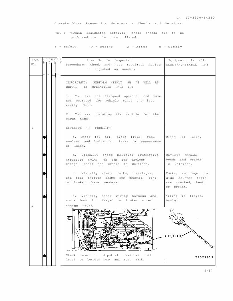
NOTE : Within designated interval, these checks are to be
performed in the order listed.
B - Before D - During A - After W - W e e k l y
Item
N0.
I n t e v a lB D A W
1
2
— — —
Item To Be Inspected Equipment Is NOT
Procedure: Check and have repaired, filled READY/AVAILABLE IF:
or adjusted as needed.
IMPORTANT: PERFORM WEEKLY (W) AS WELL AS
BEFORE (B) OPERATIONS PMCS IF:
1. You are the assigned operator and have
not operated the vehicle since the last
weekly PMCS.
2. You are operating the vehicle for the
first time.
EXTERIOR OF FORKLIFT
a. Check for oil, brake fluid, fuel, Class III leaks.
coolant and hydraulic, leaks or appearance
of leaks.
b. Visually check Rollover Protective Obvious damage,
Structure (ROPS) or cab for obvious bends and cracks
damage, bends and cracks in weldment. in weldment.
c. Visually check forks, carriages, Forks, carriage, or
and side shifter frame for cracked, bent side shifter frame
or broken frame members. are cracked, bent
or broken.
d. Visually check wiring harness and Wiring is frayed,
connections for frayed or broken wires. broken.
ENGINE LEVEL
Check level on dipstick. Maintain oil
level to between ADD and FULL mark. ITA327919
2-17
TM 10-3930-643-10
Operator/Crew Preventive Maintenance Checks and Services
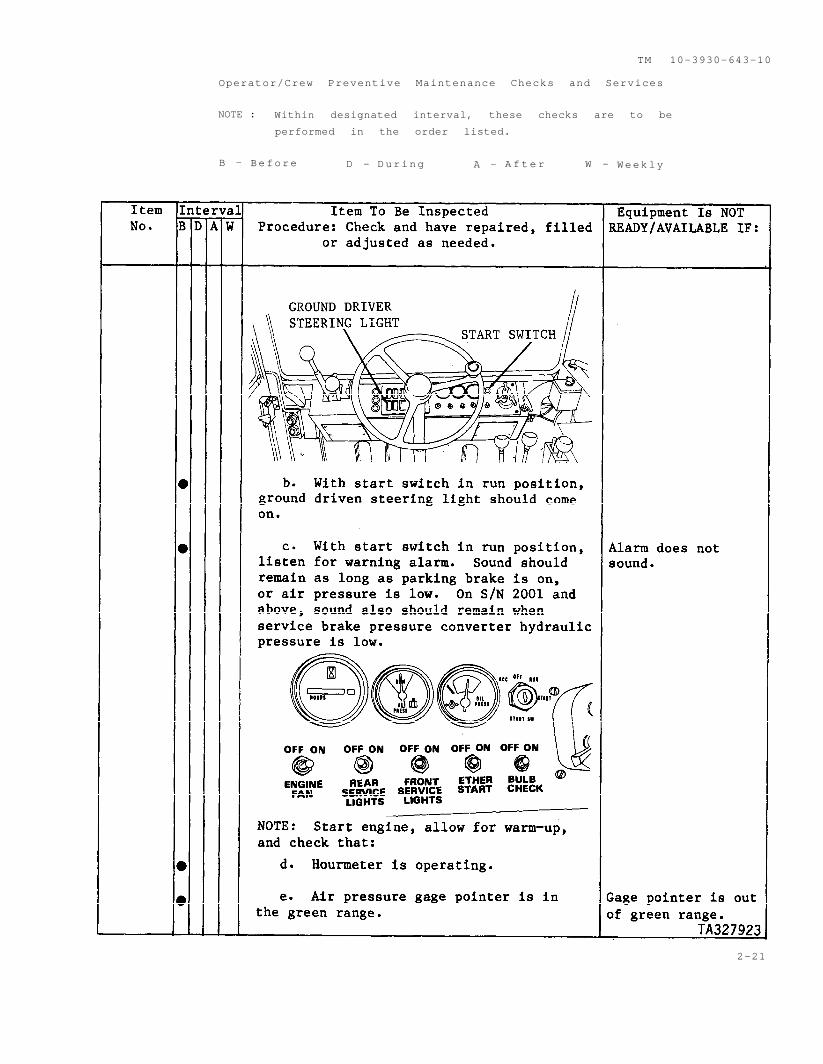
NOTE : Within designated interval, these checks are to be
performed in the order listed.
B - Before D - During A - A f t e r W - Weekly
2-18
WARNING
T M 1 0 - 3 9 3 0 - 6 4 3 - 1 0
Item
No.
4
5
Operator/Crew Preventive Maintenance Checks and Services
NOTE : Within designated interval, these checks are to be
performed in the order listed.
B - Before D - During A - After W - Weekly
I n t e r v a lE q u i p m e n t I s N o t
B D A W
Item To Be Inspected
Procedure: Check and have repaired, filled
or adjusted as needed. READY/AVAILABLE IF:
HYDRAULIC RESERVOIR
Turn hydraulic reservoir cap
slowly before opening/releasing
pressure.
With boom lowered, check reservoir oil
level at sight gage. Maintain oil so that
float is in view of sight gage. Refer to
LO 10-3930-643-12.
TIRES AND WHEELS
a. Visually check tires for excessive
wear, foreign objects, cuts or abrasions
and obviously low or flat condition.
Refer to TM 9-2610-201-14.
Tires have cuts
abrasions which
would resul
tire failure or
tire is flat
TA327921
2 - 1 9
TM 10-3930-643-10
I t e m
No l
IntervalB D A W
6
Operator/crew preventive Maintenance Checks and Services
NOTE: Within designated interval, these checks are to be
performed in the order listed.
B - Before D - During A - After W - W e e k l y
Item To Be Inspected
Procedure: Check and have repaired, filled
or adjusted as needed.
b. Check wheels for loose or missing
mounting bolts.
SEAT BELTS
Check that belt is securely mounted,
material is not frayed and latch is
operable.
INSTRUMENT WARNING LIGHTS AND ALARM
a. With fan switch off, engine off,
ignition on, press bulb check switch.
AU instrument panel lights (except oil
pressure, ground driven steering and low
air lights) should come on.
Equipment Is NOT
READY/AVAILABLE IF:
One or more bolts
missing.
Belt not securely
mounted, latch
inoperable.
Any warning light
hat does not
have a gage not
functioning.
T A 3 2 7 9 2 2
2 - 2 0
TM 10-3930-643-10
Operator/Crew Preventive Maintenance Checks and Services
NOTE : Within designated interval, these checks are to be
performed in the order listed.
B - Before D - During A - A f t e r W - Weekly
2-21
TM 10-3930-643-10
I t e m
No.
Operator/Crew Preventive Maintenance Checks and Services
NOTE : Within designated interval, these checks are to be
performed in the order listed.
B - Before D - During A - A f t e r W - Weekly
Item To Be Inspected
Procedure: Check and have repaired, filled
or adjusted as needed.
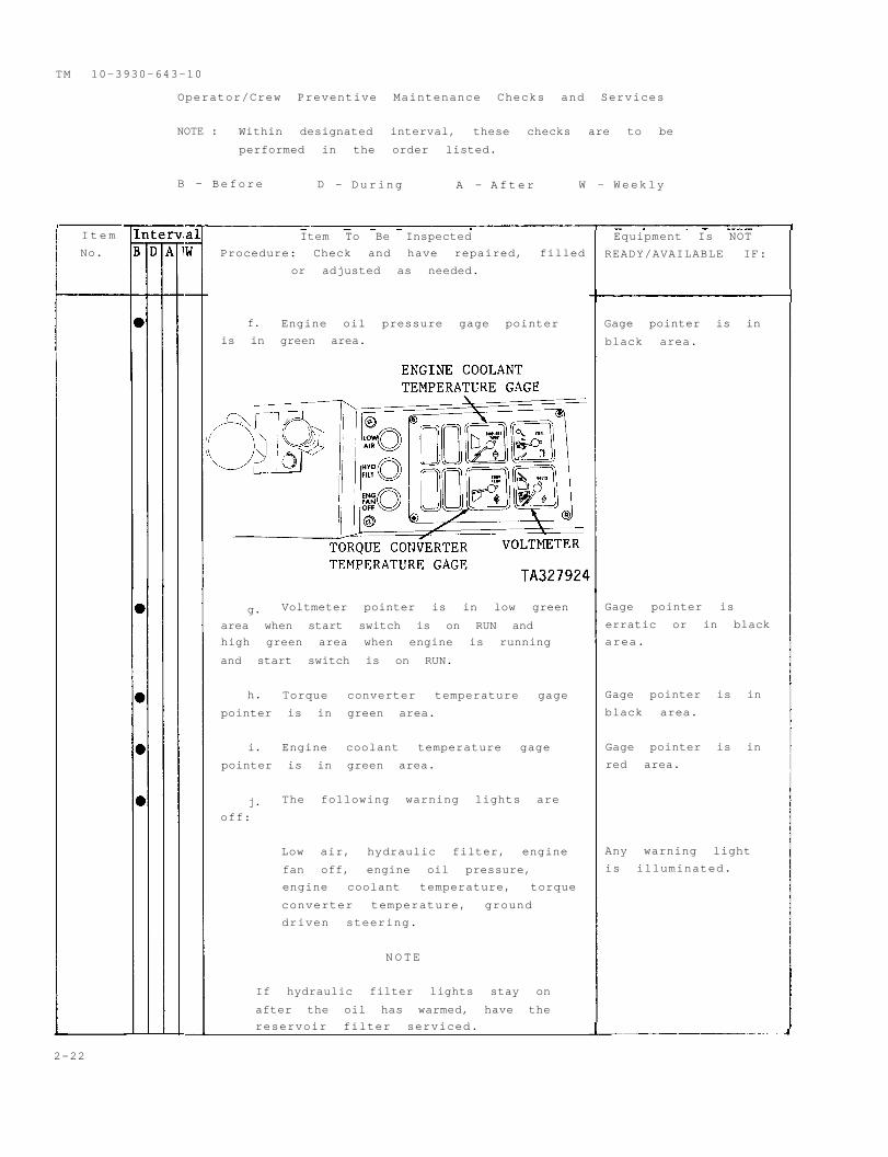
f. Engine oil pressure gage pointer
is in green area.
g. Voltmeter pointer is in low green
area when start switch is on RUN and
high green area when engine is running
and start switch is on RUN.
h. Torque converter temperature gage
pointer is in green area.
i. Engine coolant temperature gage
pointer is in green area.
j. The following warning lights are
off:
Low air, hydraulic filter, engine
fan off, engine oil pressure,
engine coolant temperature, torque
converter temperature, ground
driven steering.
N O T E
If hydraulic filter lights stay on
after the oil has warmed, have the
reservoir filter serviced.
Equipment Is NOT
READY/AVAILABLE IF:
Gage pointer is in
black area.
Gage pointer is
erratic or in black
area.
Gage pointer is in
black area.
Gage pointer is in
red area.
Any warning light
is illuminated.
2-22
TM 10-3930-643-10
Operator/Crew Preventive Maintenance Checks and Services
NOTE: Within designated interval, these checks are to be
performed in the order listed.
B - Before D - During A - A f t e r W - W e e k l y
2-21
TM 10-3930-643-10
I t e m
No.
Operator/Crew Preventive Maintenance Checks and Services
NOTE: Within designated interval, these checks are to be
performed in the order listed.
B - Before D - During A - A f t e r W - Weekly
Item To Be Inspected
Procedure: Check and have repaired, filled
or adjusted as needed.
f. Engine oil pressure gage pointer
is in green area.
g. Voltmeter pointer is in low green
area when start switch is on RUN and
high green area when engine is running
and start switch is on RUN.
h. Torque converter temperature gage
pointer is in green area.
i. Engine coolant temperature gage
pointer is in green area.
j. The following warning lights are
off:
Low air, hydraulic filter, engine
fan off, engine oil pressure,
engine coolant temperature, torque
converter temperature, ground
driven steering.
NOTE
If hydraulic filter lights stay on
after the oil has warmed, have the
reservoir filter serviced.
Equipment Is NOT
READY/AVAILABLE IF:
Gage pointer is in
black area.
Gage pointer is
erratic or in black
area.
Gage pointer is in
black area.
Gage pointer is in
red area.
Any warning light
is illuminated.
2-22
TM 10-3930-643-10
Operator/Crew Preventive Maintenance Checks and Services
NOTE: Within designated interval, these checks are to be
performed in the order listed.
B - Before D - During A - A f t e r W - Weekly
2-23
TM 10-3930-643-10
Operator/Crew Preventive Maintenance Checks and Services
NOTE: Within designated interval, these checks are to be
performed in the order listed.
B - Before D - During A - After W - Weekly
2-24
TM 10-3930-643-10
Operator/Crew Preventive Maintenance Checks and Services
NOTE: Within designated interval, these checks are to be
performed in the order listed.
B - Before D - During A - After W - Weekly
2-25
WARNING
TM 10-3930-643-10
Operator/Crew Preventive Maintenance Checks and Services
NOTE: Within designated interval, these checks are to be
performed in the order listed.
B - Before D - During A - A f t e r W - Weekly
Equipment Is NOT
Procedure: Check and have repaired, filled READY/AVAILABLE IF:
or adjusted as needed.
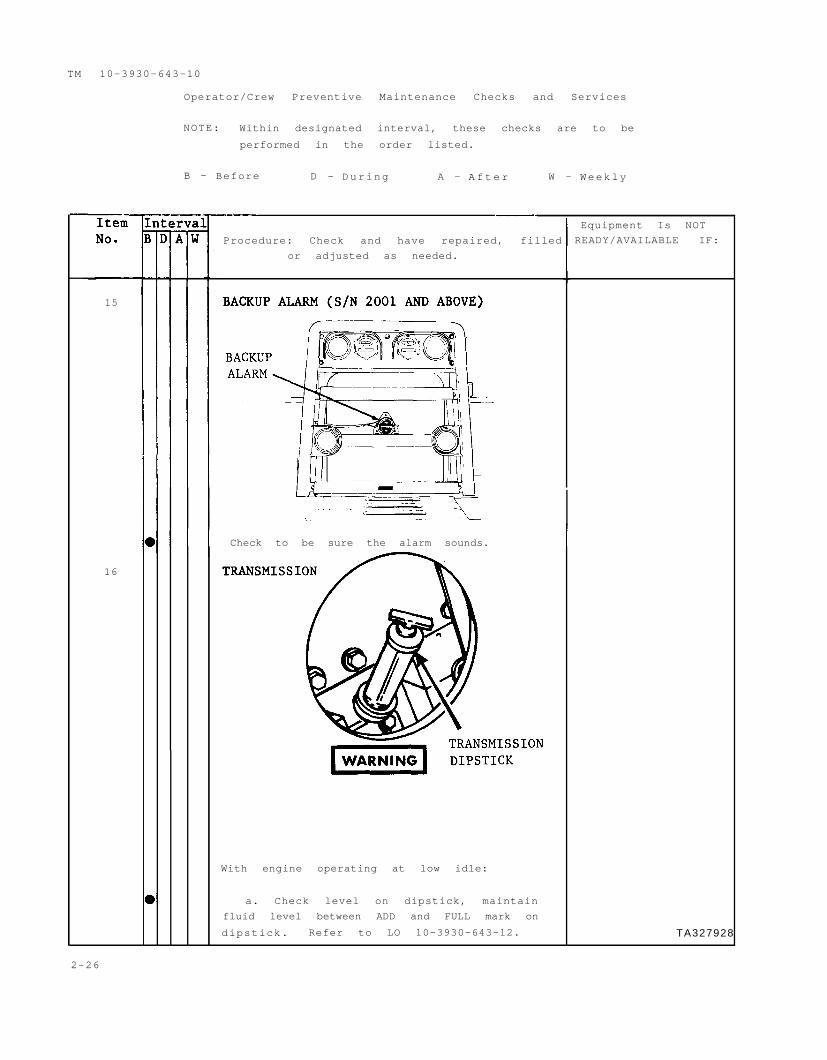
15
Check to be sure the alarm sounds.
16
With engine operating at low idle:
a. Check level on dipstick, maintain
fluid level between ADD and FULL mark on
dipstick. Refer to LO 10-3930-643-12. TA327928
2-26
TM 10-3930-643-10
Operator/Crew Preventive Maintenance Checks and Services
NOTE : Within designated interval, these checks are to be
performed in the order listed.
B - Before D - During A - A f t e r W - Weekly
I t e m
No.
Interval
B D A W
17
Item To Be Inspected
Procedure: Check and have repaired, filled
or adjusted as needed.
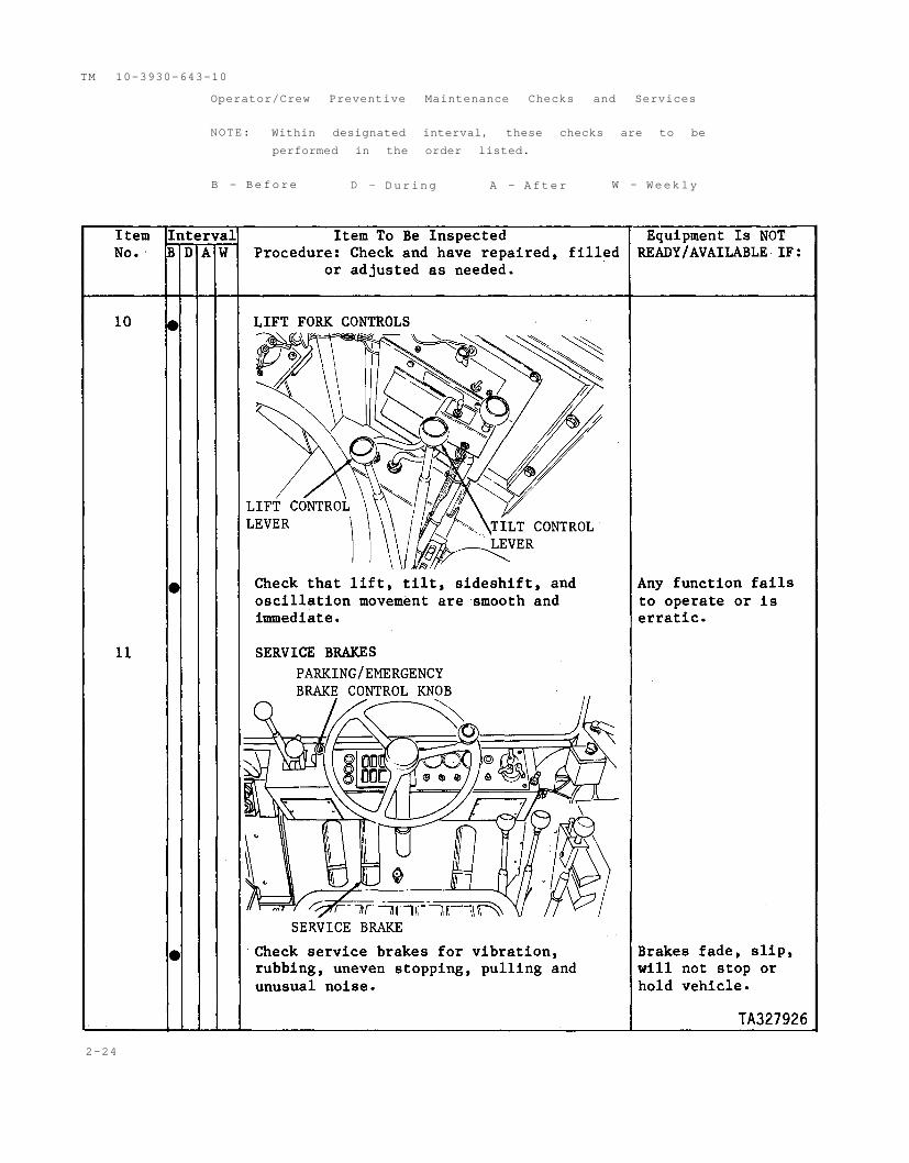
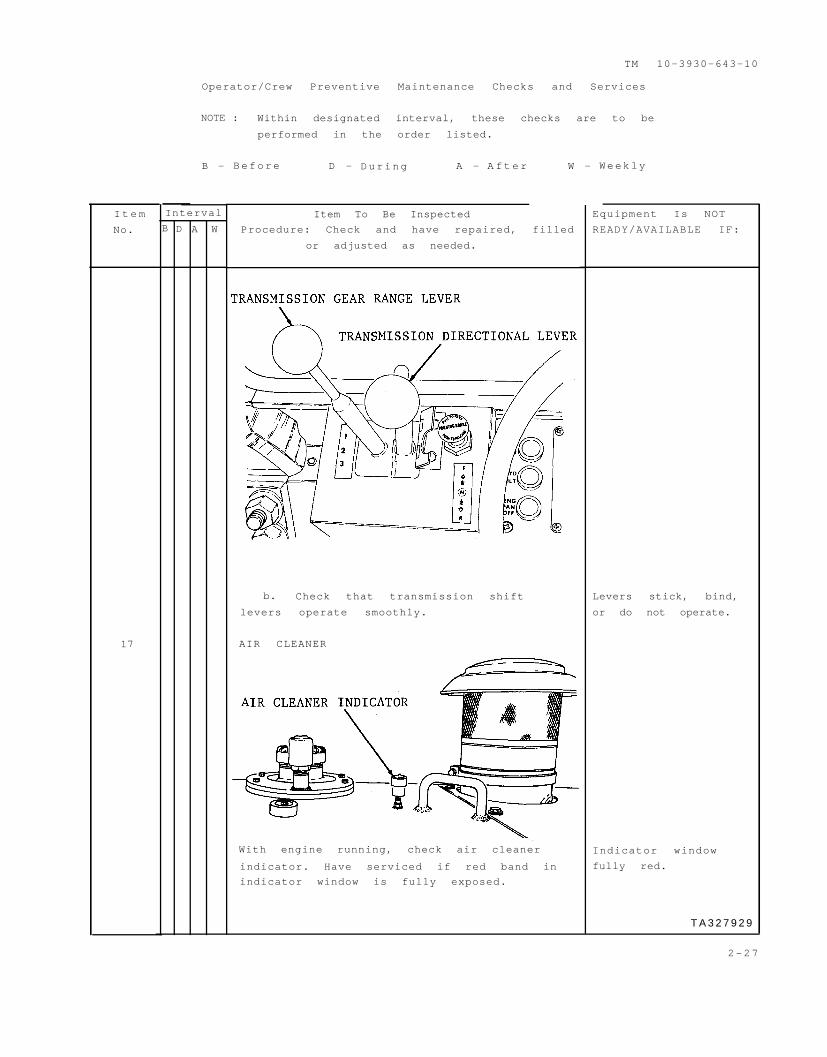
b. Check that transmission shift
levers operate smoothly.
AIR CLEANER
With engine running, check air cleaner
indicator. Have serviced if red band in
indicator window is fully exposed.
Equipment Is NOT
READY/AVAILABLE IF:
Levers stick, bind,
or do not operate.
Indicator window
fully red.
T A 3 2 7 9 2 9
2-27
TM 10-3930-643-10
Operator/Crew Preventive Maintenance Checks and Services
NOTE: Within designated interval, these checks are to be
performed in the order listed.
B - Before D - During A - After W - Weekly
2-28
I t e m
No.
Interval E q u i p m e n t I s N o tB D A W READY/AVAILABLE IF:
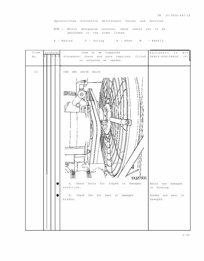
20
TM 10-3930-643-10
Operator/Crew Preventive Maintenance Checks and Services
NOTE : Within designated interval, these checks are to be
performed in the order listed.
B - Before D - During A - After W - Weekly
Item To Be Inspected
Procedure: Check and have repaired, filled
or adjusted as needed.
FAN AND DRIVE BELTS
a. Check belts for frayed or damaged
condition.
b. Check fan for bent or damaged
blades.
Belts are damaged
or missing.
Blades are bent or
damaged
2-29
WARNING
WARNING
TM 10-3930-643-10
Item
No.
Interval
B D A W
21
Operator/Crew Preventive Maintenance Checks and Services
NOTE : Within designated interval, these checks are to be
performed in the order listed.
B - Before D - During A - After W - Weekly
Item To Be Inspected
Procedure: Check and have repaired, filled
or adjusted as needed.
BATTERIES
Sulfuric acid contained in batter-
ies can cause severe chemical
burns if not handled properly.
Do not smoke or allow any flame or
spark in the vicinity while check-
ing the battery. The battery
generates hydrogen, a highly
explosive gas.
Check electrolyte level. Refer to
TM 9-6120-200-14. If level of electrolyte
is below the top of the battery plates,
notify organizational maintenance.
b. Check battery and battery box for
corrosion and obvious damage.
Equipment Is NOT
READY/AVAILABLE IF:
Battery cracked,
missing or engine
will not crank.
2-30
WARNING
WARNING
TM 10-3930-643-10
adjust lever back and adjust forward
(3) Do not use the streeing wheel as
Section III. OPERATION UNDER USUAL CONDITIONS
Before starting engine and operating forklift,
thoroughly familiar with the information in this
Review all warnings and safety precautions.
2-19. INITIAL ADJUSTMENTS, DAILY CHECKS, AND SELF TEST.
a. Lubricate. Refer to LO 10-3930-643-12.
b. Perform Before (B) PMCS. Refer to paragraph 2-18.
c. Mounting and Dismounting.
be
manual .
(1) Use steps and grab irons when mounting or dismounting the forklift.
(2) Face the forklift when mounting or dismounting.
a r t i c u l a t e i f r u n n i n g .
(4) Do not jump off the forklift.
d. A d j u s t t h e s e a t . Pull the
or rearward as desired. Do not adjust
the seat while the forklift is in
m o t i o n .
Seat belt must be fastened at
all times during operation of
the forklift.
e. Fasten and Adjust the Seat Belt.
(1) Lengthen. Hold the single
strap and pull the slide (1) toward
the buckle (2). Adjust the buckle (2)to the full extension.
(2) Shorten. Hold the slide (1) and
pull the bottom of the loop toward the
buckle (2). Adjust the buckle (2) to
the full extension.
a hand hold. The forklift could
2-31
TM 10-3930-643-10
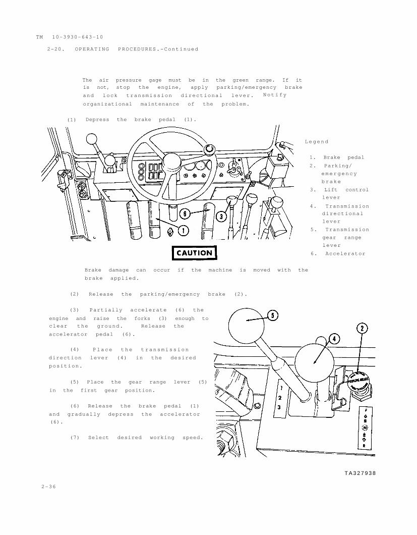
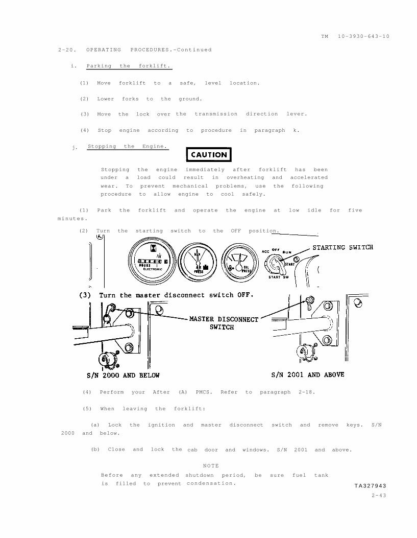
2-20. OPERATING PROCEDURES.
a. Starting the Engine.
NOTE
Check log book to determine period of non-operation. If
engine has been idle for 30 days or more the turbo-
charger must be primed before starting engine. Notify
organizational maintenance.
(1) Before entering cab, turn the Master Disconnect switch ON. Do not
Liberated Manuals -- free army and government manuals
Why do I do it? I am tired of sleazy CD-ROM sellers, who take publicly available information, slap “watermarks” and other junk on it, and sell it. Those masters of search engine manipulation make sure that their sites that sell free information, come up first in search engines. They did not create it... They did not even scan it... Why should they get your money? Why are not letting you give those free manuals to your friends?
I am setting this document FREE. This document was made by the US Government and is NOT protected by Copyright. Feel free to share, republish, sell and so on.
I am not asking you for donations, fees or handouts. If you can, please provide a link to liberatedmanuals.com, so that free manuals come up first in search engines:
<A HREF=http://www.liberatedmanuals.com/>Free Military and Government Manuals</A>