1067 POSITIONER TYPE 1067 E-1- TABLE OF CONTENTS 1 INTRODUCTION ................................................................................................................ E-2 1.1 Unpacking and inspecting .................................................................................................. E-2 1.2 General notes on use and safety ....................................................................................... E-2 1.3 Electromagnetic compatibility ............................................................................................ E-2 2 DESCRIPTION ................................................................................................................... E-3 2.1 Characteristics and possible applications ......................................................................... E-3 2.2 Construction ....................................................................................................................... E-5 2.3 Principle of operation ......................................................................................................... E-6 2.4 Safety position .................................................................................................................... E-7 2.5 Technical data .................................................................................................................... E-8 3 INSTALLATION ................................................................................................................. E-9 3.1 Construction and assembly ................................................................................................ E-9 3.1.1 Fitting the positioner to a continuous valve with membrane drive (NAMUR) .......... E-9 3.1.2 Fitting the positioner to a type 2031 continuous valve with piston drive ............... E-11 3.1.3 Fitting the positioner to a continuous valve with rotary drive ................................. E-13 3.2 Fluid ports ......................................................................................................................... E-14 3.3 Electrical connections ...................................................................................................... E-15 4 OPERATION .................................................................................................................... E-16 4.1 Controls and indicators .................................................................................................... E-16 4.2 Operating levels ............................................................................................................... E-17 4.3 Setting up ......................................................................................................................... E-18 4.4 Process control ................................................................................................................. E-19 4.4.1 Meaning of LEDs and keys in the process control level ........................................ E-20 4.4.2 Displays ................................................................................................................... E-20 4.5 Configuration .................................................................................................................... E-21 4.5.1 Additional functions ................................................................................................. E-21 4.5.2 Configuration menu ................................................................................................. E-22 4.5.3 Function of keys in the configuration level ............................................................. E-25 4.5.4 Notes on the basic and additional functions .......................................................... E-25 4.6 Manual operation without power supply .......................................................................... E-34 4.7 Structure of the positioner ................................................................................................ E-35 5 MAINTENANCE ............................................................................................................... E-36 Fault messages ................................................................................................................ E-36 APPENDIX ....................................................................................................................... E-37 A1: Characteristics of PID controllers .............................................................................. E-37 A2: Rules for adjusting PID controllers ............................................................................ E-39 A3: Optional board for analog position indication ............................................................ E-44 A4: Optional board for binary position indication/Booster ............................................... E-45
Transcript
1067
POSITIONER TYPE 1067
E-1-
TABLE OF CONTENTS
1 INTRODUCTION ................................................................................................................ E-21.1 Unpacking and inspecting .................................................................................................. E-21.2 General notes on use and safety ....................................................................................... E-21.3 Electromagnetic compatibility ............................................................................................ E-2
2 DESCRIPTION ................................................................................................................... E-32.1 Characteristics and possible applications ......................................................................... E-32.2 Construction ....................................................................................................................... E-52.3 Principle of operation ......................................................................................................... E-62.4 Safety position .................................................................................................................... E-72.5 Technical data .................................................................................................................... E-8
3 INSTALLATION ................................................................................................................. E-93.1 Construction and assembly ................................................................................................ E-9
3.1.1 Fitting the positioner to a continuous valve with membrane drive (NAMUR) .......... E-93.1.2 Fitting the positioner to a type 2031 continuous valve with piston drive ............... E-113.1.3 Fitting the positioner to a continuous valve with rotary drive ................................. E-13
4 OPERATION .................................................................................................................... E-164.1 Controls and indicators .................................................................................................... E-164.2 Operating levels ............................................................................................................... E-174.3 Setting up ......................................................................................................................... E-184.4 Process control ................................................................................................................. E-19
4.4.1 Meaning of LEDs and keys in the process control level ........................................ E-204.4.2 Displays ................................................................................................................... E-20
4.5 Configuration .................................................................................................................... E-214.5.1 Additional functions ................................................................................................. E-214.5.2 Configuration menu ................................................................................................. E-224.5.3 Function of keys in the configuration level ............................................................. E-254.5.4 Notes on the basic and additional functions .......................................................... E-25
4.6 Manual operation without power supply .......................................................................... E-344.7 Structure of the positioner ................................................................................................ E-35
APPENDIX ....................................................................................................................... E-37A1: Characteristics of PID controllers .............................................................................. E-37A2: Rules for adjusting PID controllers ............................................................................ E-39A3: Optional board for analog position indication............................................................ E-44A4: Optional board for binary position indication/Booster ............................................... E-45
E-2-1067
POSITIONER TYPE 10671 INTRODUCTION
Dear Customer,
We congratulate you on the purchase of ourpositioner type 1067. You have made a goodchoice. To be able to make the best use of themany advantages the product has to offer, it isabsolutely necessary to follow our advice and
READ THESE OPERATING INSTRUC-TIONS CAREFULLY BEFORE FITTINGTHE UNIT AND PUTTING IT INTOSERVICE
1.1 Unpacking and inspecting
Please check the delivery for completeness andtransportation damage. The standard deliveryincludes:
In the event of loss or damage please contactyour Bürkert Subsidiary.
1.2 General notes on use andsafety
This publication contains no warranty statementFor this we refer to our general purchase anddelivery conditions.To ensure proper functioning and a long life ofthe positioner, the user must observe theseOperating Instructions as well as complying withthe installation conditions and permissible dataas given in the data sheet. Installation andmaintenance personnel must have training andqualifications suitable for the task.
Suitable measures are to be taken to preventunintentional actuation and the resulting effecton the process. Safe electrical isolating and shut-off devices for the media must be provided forthe installation task. If the positioner is part of acomplex automated system, a defined andcontrolled restart of the automated system afteran interruption shall be guaranteed in accordancewith the instructions.The accident and prevention safety regulations
for electrical equipment shall be complied withduring the operation, servicing and repair of thepositioner.
Repairs may only be carried out by authorisedtrained personnel.
This symbol is shown in the OperatingInstructions each time particular careis required to ensure correctinstallation, functioning and operating
safety of the equipment.
1.3 Electromagnetic compatibility
This device conforms to the EMC-Directive ofthe Council of European Communities89/336/EEC.In order to comply with this directive, the wiringinstructions must be followed.
Master codeUnauthorised operation can be prevented at thevarious operating levels by a freely-selectableuser code. Independent of this, there is a fixed,programmed master code which cannot bechanged, by means of which all operations canbe performed. This four-digit master code isgiven on the bottom margin of this page. Itcan be cut out and kept separately from theseOperating Instructions.
Master code:6568
!
1067
POSITIONER TYPE 1067
E-3-
2 DESCRIPTION
2.1 Characteristics and possible applications (overview)
The type 1067 positioner is an electropneumatic position controller for pneumatically actuatedcontinuous valves. The device includes the following main functional groups: a feedback/positionaltransducer, an electropneumatic system and a microprocessor electronic system. The feedback/positional transducer measures the actual position of the continuous valve. The microprocessorelectronic system continuously compares the actual position (actual value) with a desired positionvalue that was preset via the standard signal input and supplies the result to the position controller.If an error exists, the electropneumatic system causes the actual position to be appropriately corrected.
The type 1067 positioner can be fitted to various continuous valves (e.g. valves with piston, membraneor rotary drives and with single or double action). Two variant forms of the basic device are offeredthat differ in their fixing options and feedback/positional transducers. In variant 1, an internal feedback/positional transducer is used that takes the form of a rotary potentiometer. In variant 2, an externallinear potentiometer serves as feedback/positional transducer.
The positioner also implements a PID controller by means of which, in addition to position control,process control (e.g. level, pressure, flow or temperature control) can be achieved in the form ofsequence control.
A liquid-crystal display and a keypad with three keys are provided for operating the positioner. Anoperating concept with the following graded operating levels has been implemented:
- Process operationThis level allows switching between automatic and manual operation, and enables manual actuation.
- ConfigurationConfiguration level is used to specify certain basic functions when the positioner is taken into serviceand, if necessary, to configure additional functions.
E-4-1067
POSITIONER TYPE 10672 DESCRIPTION
Fig. 1 Block diagram of the type 1067 positioner
Positionertype 1067
Input for process actualvalue
4...20 mA
Input for position orprocess setpoint
0...10 V0...20 mA4...20 mA
24 VDC
Binary input (contact)
Analog output (option)
RS 232 (option)
RS 485 / PROFIBUS(option)
Operation
Characteristics, functions
Inp
uts
Po
wer
Ou
tpu
tIn
terf
aces
Position controller withadditional functions, e. g.- close tight function- plug travel limitation- setting speed limitation- split range- correction characteristics- deadband- safety position
Additional integrated processcontroller with the following features:- adjustable parameters- scalable inputs- setpoint setting via input signal or
keys
Automatic adaptation of positioncontroller to the continuous valve inuse
The positioner consists of the following main assemblies:- Body and bonnet (aluminium)- internal feedback/positional transducer for measuring valve position- Microprocessor/electronic unit for signal processing and control- Solenoid valves for control of a continuous action valve- Fluid plate with fluid ports- Terminals and cable glands- Display and keyboard
Fig. 2 Cross section of the positioner with internal feedback/positional transducer
Connectionterminal
Manual operation
Cable gland
Display and keypad
Fluid plate
Fluid portsSolenoid valve
Aluminium body andbonnet with hinge Electronic
In variant 2, an external linear potentiometer serves as feedback/positional transducer (see fig. 3).
Fig. 3 External feedback/positional transducer
Positionaltransducer shaft
Internal feedback/positional transducer forconnection according toNAMUR
E-6-1067
POSITIONER TYPE 10672 DESCRIPTION
2.3 Principle of operation
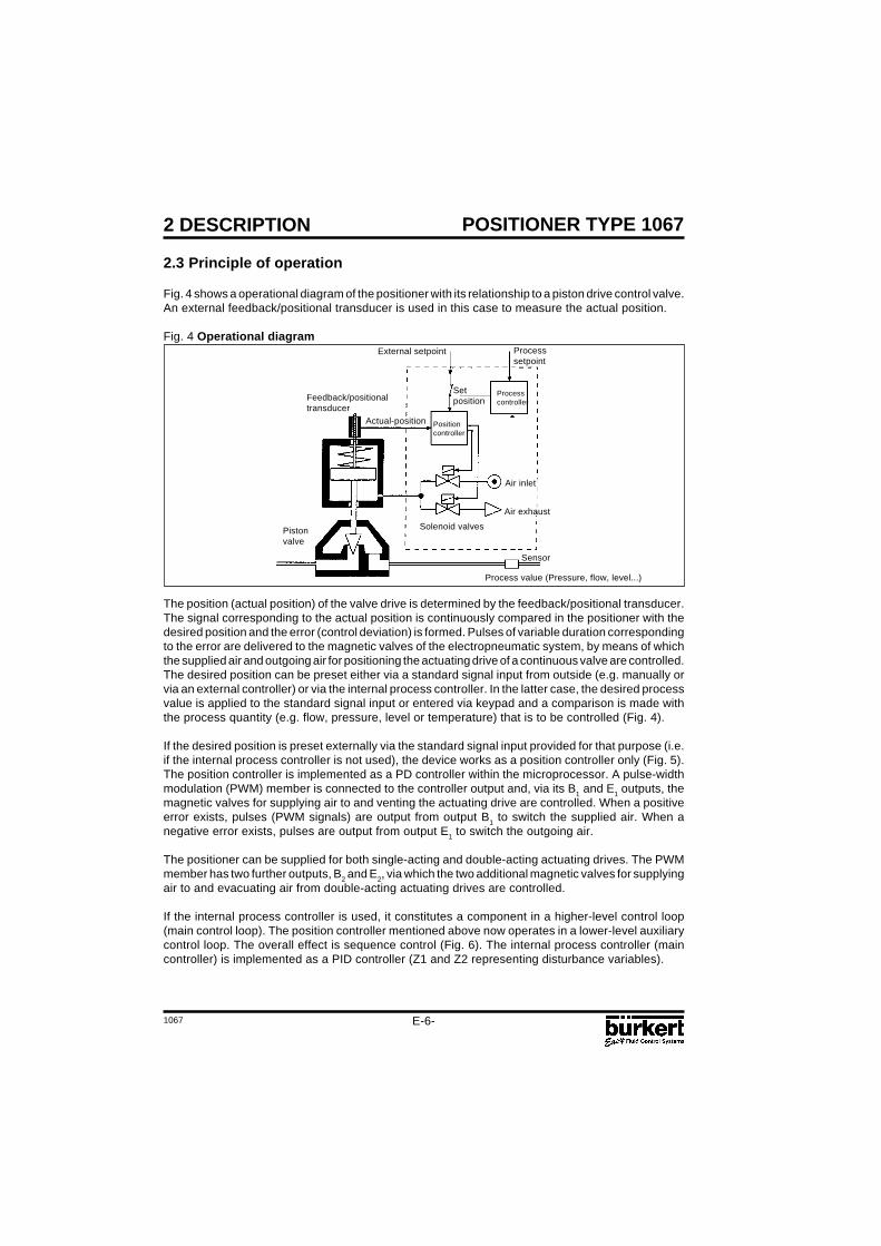
Fig. 4 shows a operational diagram of the positioner with its relationship to a piston drive control valve.An external feedback/positional transducer is used in this case to measure the actual position.
Fig. 4 Operational diagram
Pistonvalve
Air inlet
Solenoid valves
Air exhaust
Positioncontroller
Setposition
Process value (Pressure, flow, level...)
Sensor
Processcontroller
The position (actual position) of the valve drive is determined by the feedback/positional transducer.The signal corresponding to the actual position is continuously compared in the positioner with thedesired position and the error (control deviation) is formed. Pulses of variable duration correspondingto the error are delivered to the magnetic valves of the electropneumatic system, by means of whichthe supplied air and outgoing air for positioning the actuating drive of a continuous valve are controlled.The desired position can be preset either via a standard signal input from outside (e.g. manually orvia an external controller) or via the internal process controller. In the latter case, the desired processvalue is applied to the standard signal input or entered via keypad and a comparison is made withthe process quantity (e.g. flow, pressure, level or temperature) that is to be controlled (Fig. 4).
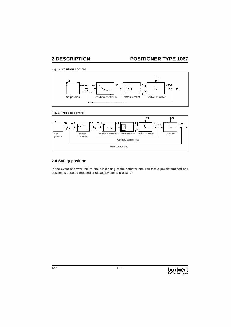
If the desired position is preset externally via the standard signal input provided for that purpose (i.e.if the internal process controller is not used), the device works as a position controller only (Fig. 5).The position controller is implemented as a PD controller within the microprocessor. A pulse-widthmodulation (PWM) member is connected to the controller output and, via its B1 and E1 outputs, themagnetic valves for supplying air to and venting the actuating drive are controlled. When a positiveerror exists, pulses (PWM signals) are output from output B1 to switch the supplied air. When anegative error exists, pulses are output from output E1 to switch the outgoing air.
The positioner can be supplied for both single-acting and double-acting actuating drives. The PWMmember has two further outputs, B2 and E2, via which the two additional magnetic valves for supplyingair to and evacuating air from double-acting actuating drives are controlled.
If the internal process controller is used, it constitutes a component in a higher-level control loop(main control loop). The position controller mentioned above now operates in a lower-level auxiliarycontrol loop. The overall effect is sequence control (Fig. 6). The internal process controller (maincontroller) is implemented as a PID controller (Z1 and Z2 representing disturbance variables).
Feedback/positionaltransducer
Actual-position
External setpoint Processsetpoint
1067
POSITIONER TYPE 1067
E-7-
2 DESCRIPTION
Fig. 5 Position control
Position controller Valve actuatorPWM elementSetposition
Fig. 6 Process control
Process
Auxiliary control loop
Main control loop
Setposition
2.4 Safety position
In the event of power failure, the functioning of the actuator ensures that a pre-determined endposition is adopted (opened or closed by spring pressure).
Processcontroller
Position controller PWM-element Valve actuator
E-8-1067
POSITIONER TYPE 10672 DESCRIPTION
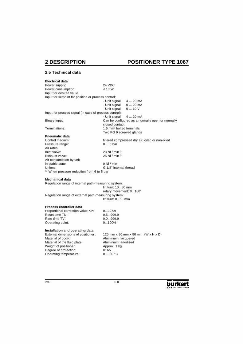
2.5 Technical data
Electrical dataPower supply: 24 VDCPower consumption: < 10 WInput for desired valueInput for setpoint for position or process control:
- Unit signal 4 ... 20 mA- Unit signal 0 ... 20 mA- Unit signal 0 ... 10 V
Input for process signal (in case of process control):- Unit signal 4 ... 20 mA
Binary input: Can be configured as a normally open or normallyclosed contact.
Air consumption by unitin stable state: 0 Nl / minUnions: G 1/8" internal thread(1) When pressure reduction from 6 to 5 bar
Mechanical dataRegulation range of internal path-measuring system:
lift turn: 10...80 mmrotary movement: 0...180°
Regulation range of external path-measuring system:lift turn: 0...50 mm
Process controller dataProportional correction value KP: 0...99,99Reset time TN: 0.5...999.9Rate time TV: 0.0...999.9Operating point: 0...100%
Installation and operating dataExternal dimensions of positioner : 125 mm x 80 mm x 80 mm (W x H x D)Material of body: Aluminium, lacqueredMaterial of the fluid plate: Aluminium, anodisedWeight of positioner: Approx. 1 kgDegree of protection: IP 65Operating temperature: 0 ... 60 °C
1067
POSITIONER TYPE 1067
E-9-
3 INSTALLATION
3.1 Construction and assembly
The type 1067 positioner can be fitted to various continuous valves. Depending on the valve typeeither variant 1, with an internal feedback/positional transducer (a rotary potentiometer) or variant 2,with an external feedback/positional transducer (a linear potentiometer) is used (see section 2.3).
Main dimensions: Positioner External feedback/positional transducerWidth: 125 mm Diameter: approx. 65 mmHeight: 80 mm Height: approx. 95 (115) mmDepth: 80 mm
3.1.1 Fitting the positioner to a continuous valve with membrane drive (according to NAMUR)
Arrangement
In the case of a continuous valve with membrane drive, device variant 1, with an internal feedback/positional transducer (a rotary potentiometer) should be used. The positioner is screwed on to whatis termed the «lantern» of the membrane drive (Fig. 7). Transmission of the valve position to theinternal feedback/positional transducer is achieved by means of a lever conforming to NAMUR(Fig. 8).
Assembly
A mounting elbow (Fig. 10) is provided for assembling variant 1 of the positioner to a continuous valvewith membrane drive (e.g. Type 265). The following steps should be carried out:
Screw mounting elbow to the positioner using 4 x M6 screws.Fasten pin using washer and nut to that position of the lever which corresponds with thedesired lift (the lever is marked in mm of lift).Put lever with pin on to the path-sensor shaft of the positioner so that the marking on the shaftpoints towards the pin on the lever. Then screw lever tight with screw . Fasten carrier withcheese-head bolts to the lifting rod of the membrane valve.
Fig. 7 Fitting to a type 265 continuous valvewith membrane drive
Fig. 8 Rear view of positioner (variant 1) withlever
E-10-1067
POSITIONER TYPE 1067
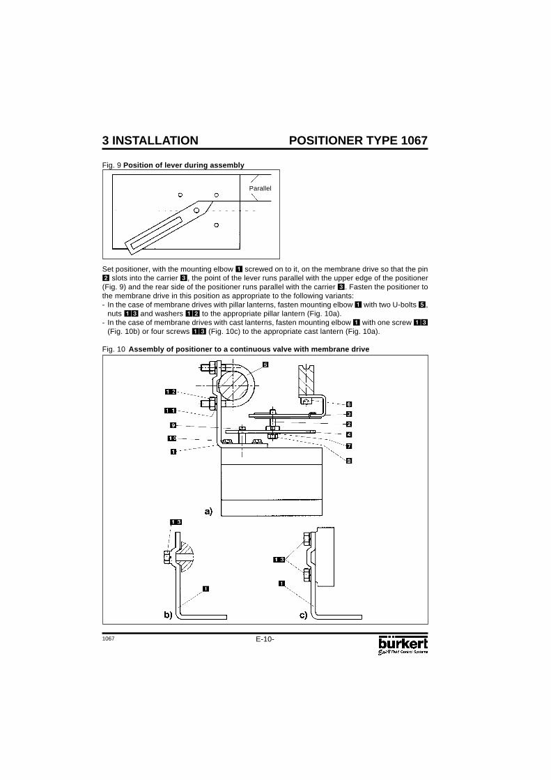
Fig. 9 Position of lever during assembly
3 INSTALLATION
Set positioner, with the mounting elbow screwed on to it, on the membrane drive so that the pin slots into the carrier , the point of the lever runs parallel with the upper edge of the positioner(Fig. 9) and the rear side of the positioner runs parallel with the carrier . Fasten the positioner tothe membrane drive in this position as appropriate to the following variants:- In the case of membrane drives with pillar lanterns, fasten mounting elbow with two U-bolts ,
nuts and washers to the appropriate pillar lantern (Fig. 10a).- In the case of membrane drives with cast lanterns, fasten mounting elbow with one screw
(Fig. 10b) or four screws (Fig. 10c) to the appropriate cast lantern (Fig. 10a).
Fig. 10 Assembly of positioner to a continuous valve with membrane drive
Parallel
1067
POSITIONER TYPE 1067
E-11-
Fig. 11 Fitting to a type 2031 continuousvalve with piston drive
Fig. 12 Rear view of positioner (variant 2)
Assembly
Assembly of variant 2 of the positioner to a type 2031 continuous valve with piston drive.
A set of add-on parts (NAMUR adapter, Fig. 13) is provided for assembling variant 2 of the positionerto a piston valve (e.g. type 2031). It consists of a mounting plate , two hollow bolts , three O-rings and two cheese-head bolts M5 .
To assemble the positioner on a type 2031 continuous valve with piston drive, the following stepsshould be carried out (Fig. 13):
Place an O-ring in the recess of the mounting plate (drive side). In the case of a large version,place a second O-ring on the other side of the mounting plate.Put two cheese-head bolts M5 from the drive side through the 5-mm drillings in the mounting plate.Screw the preassembled mounting plate to the two connection pieces of the valve drive with twohollow bolts so that the lower connection piece is sealed by the O-ring.Place an O-ring in the groove on the reverse side of the positioner.Add the positioner to the mounting plate and screw it on with the two cheese-head bolts .
Assembly of the external feedback/positional transducer to a type 2031 continuous valve with pistondrive.
To assemble the external feedback/positional transducer, the following steps should be carried out(Figs. 13 and 14):Check that an O-ring has been put into the valve drive (top). Insert O-ring if necessary.
3 INSTALLATION
3.1.2 Fitting the positioner to a type 2031 continuous valve with piston drive
Arrangement
In the case of a continuous valve with piston drive, variant 2 with the external path-measuring system(Fig. 3) should be used. The positioner is placed on the valve and screwed to it (Figs. 11 and 12). Thevalve position is transmitted directly via the spring-mounted rod of the path-measuring system (thelinear potentiometer).
E-12-1067
POSITIONER TYPE 1067
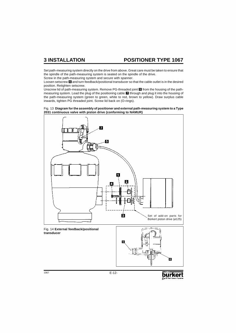
Fig. 14 External feedback/positionaltransducer
3 INSTALLATION
Set of add-on parts forBürkert piston drive (ø125)
Set path-measuring system directly on the drive from above. Great care must be taken to ensure thatthe spindle of the path-measuring system is seated on the spindle of the drive.Screw in the path-measuring system and secure with spanner.Loosen setscrew and turn feedback/positional transducer so that the cable outlet is in the desiredposition. Retighten setscrew.Unscrew lid of path-measuring system. Remove PG-threaded joint from the housing of the path-measuring system. Lead the plug of the positioning cable through and plug it into the housing ofthe path-measuring system (green to green, white to red, brown to yellow). Draw surplus cableinwards, tighten PG threaded joint. Screw lid back on (O-rings).
Fig. 13 Diagram for the assembly of positioner and external path-measuring system to a Type2031 continuous valve with piston drive (conforming to NAMUR)
1067
POSITIONER TYPE 1067
E-13-
Fig. 15 Fitting to a continuous valve withrotary drive
Fig. 16 Reverse side of positioner (variant 1)with securing holes
3 INSTALLATION
Assembly
A coupling (adapter) is provided for assembling variant 1 of the positioner on to a continuous valvewith a rotary or part-turn valve actuating drive (e.g. Type 3210, Fig. 17). In addition, an assembly clip (Fig. 18) is required and can be obtained from the manufacturer of the part-turn valve actuatingdrive. (It is normally used for the assembly of a limit-switch box).
To assemble, the following steps should be carried out (Fig. 18):
Secure the assembly clip to the valve drive.Place the coupling on the shaft of the positioner’s feedback/positional transducer. The setscrew on the coupling should first have been slightly withdrawn.Place the positioner on the assembly clip. Ensure that the flat piece of the coupling fits into the slotin the end of the drive shaft.Secure the positioner on the assembly clip with 4 x M6 screws.Fix the coupling to the shaft of the feedback/positional transducer by screwing in the setscrew .
If after the AUTOTUNE function is started the message TURN POT is displayed on the LCD, thesetscrew must be loosened and the shaft of the path-measuring system rotated 180° relative to thedrive. The setscrew should then be screwed tight and the AUTOTUNE function repeated.
3.1.3 Fitting the positioner to a continuous valve with rotary drive
Arrangement
In the case of a continuous valve with rotary or part-turn valve actuating drive, variant 1 with aninternal feedback/positional transducer should be used. Its shaft is coupled to the valve rotary drive(e.g. flap valve). The position of the rotary drive is thus transmitted directly to the shaft of thefeedback/positional transducer.
E-14-1067
POSITIONER TYPE 10673 INSTALLATION
Fig. 17 Coupling for continuous valve withrotary drive
Fig. 18 Assembly of positioner on to acontinuous valve with rotary drive
Continuous valve with rotary drive
Single acting Double acting Single acting, parallel(for higher flow)
3.2 Fluid ports
Connect P port with compressed air supply (6 bar max.)
Caution: The PE terminal must be connected to a ground point using the shortest possible cable(max. 30 cm) to ensure electromagnetic compatibility (EMC).
Signal input:- either for valveposition control- or for processregulation control
Binary inputContact
Output(Option)
Power Supply
Input for processregulation
E-16-1067
POSITIONER TYPE 10674 OPERATION
4.1 Controls and indicators
AUTOTUNE
„Arrow up“ key
„Arrow down“ key MANUAL/AUTOMATIC key
LED
4.2 Operating levels
2 operating levels are provided for operation of the positioner:
1° Process operation levelThis level, which is automatically set each time the unit is switched on, allows to change over betweenthe MANUAL and AUTOMATIC operating modes. In the MANUAL mode the valve can be openedor closed by operating the „arrow keys“.
2° Configuration levelThe purpose of the configuration level is to enable the basic functions to be specified on initialcommissioning and additional functions to be configured as required.
Each time the power is switched on, the positioner is in the process operation level in the AUTOMATICmode. A changeover to the MANUAL mode can be accomplished using the MANUAL/AUTOMATICkey (cf § 4.4). From the process operation level it is possible to change over to the configurationlevel by pressing the MANUAL/AUTOMATIC key and holding for 5 seconds.
1067
POSITIONER TYPE 1067
E-17-
4 OPERATION
4.3 Setting up
The following basic settings are to be carried out on the initial setting up (commissioning) of thepositioner in conjunction with the 2632 angle-seat control valves (specification of basic functions):- Specification of the positional feedback of the continuous valve to the positional transducer (direct
or lever),- Specification of the unit signal input chosen for entering the set position (0 ... 20 mA, 4 ... 20 mA
or 0 ... 10 V),- Initiating the automatic adaptation of the actuator to the valve being used.
When the power is switched on, the positioner is in the process control level. It is necessary to switchto the configuration level for specification of the basic functions. To do this, press the MANUAL/AUTOMATIC key and hold for 5 seconds. The first menu point X-SENS of the main menu is thendisplayed.
Fig. 21 Main menu for first setting up
Function
AUTOMATIC
or
MANUAL
after 30 to 120 sec.
BLINKING
E-18-1067
POSITIONER TYPE 10674 OPERATION
To perform a setting within the X-SENS and INPUT menu items, briefly press the MANUAL/AUTOMATIC key again. One of the menu sub-items then appears in the display. It is possible toswitch back and forwards between these sub-items, each of which describes a possible setting, byagain pressing the arrow keys. The actual setting is carried out by pressing the MANUAL/ AUTOMATICkey on the selected menu sub-item.
Fig. 22 Signification of the menu options in the main menu
Basic function Associated settings
X-SENS Type of information transfer between the actuator and travel measuringsystem (factory-set to DIRECT)
- DIRECT - Linear relationship- LEVER - Sinusoidal relationship (use of a lever)
INPUT Specification of selected unit signals- 4 ... 20 MA - Unit signal current 4 ... 20 mA- 0 ... 20 MA - Unit signal current 0 ... 20 mA- 0 ... 10 V - Unit signal voltage 0 ... 10 V
ADDFUNCT Configuration of additional functionsAUTOTUNE Actuation of automatic adaptation of the actuator to the valveEND End of menu
Under the menu option X-SENS, indicate whether the mechanical transmission of path informationfrom the positioner to the feedback/positional transducer is based on a linear or sinusoidal relationship.A sinusoidal relationship results if the lever mechanism is used for the transmission of path information(cf. section 3.1.1). In this event, when LEVER is confirmed an internal linearization takes place bymeans of an approximated sinusoidal function.
The ADDFUNCT menu item can be skipped on the initial setting up. It is used only to configureadditional functions.
The AUTOTUNE menu item is used to start the programme for automatic parametering of thepositioner. This automatically triggers the following functions:
- Matching the sensor signal to the (physical) stroke of the control valve used.- Determining parameters of PWM signals for control of the internal solenoid valves.- Optimum adjustment of the control parameters of the position controller (target function: fastest
possible movement to the set position without hunting).
The programme for automatic parametering is started by setting the AUTOTUNE menu item in themain menu and then pressing the MANUAL/AUTOMATIC key and holding for 5 seconds. TUNE isdisplayed with a countdown from 5 to 0. The word AUTOTUNE then flashes for approximately 30 to120 seconds (depending on the actuator volume). After the flashing ends, the message TUNE ENDis displayed.
Note: In case of complete delivery of a valve fitted with a positioner, the AUTOTUNE function hasalready been run through in factory. In order to obtain the best accuracy, it is recommended to runthe AUTOTUNE function once more before putting the valve in operation.
If it is not possible to fully complete the AUTOTUNE routine, an error message is displayed (refer tothe list of error messages in part 5).
1067
POSITIONER TYPE 1067
E-19-
4 OPERATION
To leave the main menu for the settings during the setting up, first select the END menu item bypressing the arrow keys. Then press the MANUAL/AUTOMATIC key to restore the unit to the operatingmode which was present before the changeover to the main menu (MANUAL or AUTOMATIC).
4.4 Process operation
4.4.1 Meaning of LEDs and keys in the process operation level
LED Green LED in the MANUAL/AUTOMATIC key is on: AUTOMATIC modeGreen LED in the MANUAL/AUTOMATIC key is off: MANUAL mode
Keys- Operation of the MANUAL/AUTOMATIC key (key pressed for less than 5 seconds) changes over
between the MANUAL and AUTOMATIC modes.- Pressing the MANUAL/AUTOMATIC key and holding for longer than 5 seconds gives entry to the
configuration menu.- Pressing the arrow keys in the AUTOMATIC mode with additional function PCONTRL SETPOINT
INTERN and display set to SP (holding for longer than 3 seconds): changes the setpoint value (seesection).
- Operation of the arrow keys in the AUTOMATIC mode (key held for less than 3 seconds) changesover the display.
- Pressing the „Arrow up“ key in the MANUAL mode moves the actuator to open.- Pressing the „Arrow down“ key in the MANUAL mode moves the actuator to closed.
4.4.2 Displays
Displays in the AUTOMATIC modeProcess controller inactiveThe following displays are possible for the position controller.Actual position of valve actuator: XPOS___ (0...100%)Set position of valve actuator: WPOS___ (0...100%)It is possible to change over between these displays by operating the „arrow keys“.
Process controller activeWhen the process controller is active, the following values can be displayed:Actual value of process variable (actual process value): PV____ (-99.9...999.9)Desired value of process variable (desired process value): SP____ (-99.9...999.9)Actual value of valve drive: XPOS____ (0...100%)Desired value of valve drive: WPOS____ (0...100%)
The arrow keys can be used to switch between these four displays. The «down arrow» key allowspaging through displayed values in the above sequence.
If the additional function PCONTROL SETPOINT INTERN (set desired value via keyboard) wasspecified during configuration, pressing either of the two arrow keys for more than 3 seconds whileSP (Setpoint) is shown in the display activates the mode for changing the desired process value. Ifthe key is released after this time, the first digit of the desired process value flashes on and off. Thisdigit can be changed by pressing the key again. After confirmation with the HAND/AUTOMATIC key,the set value is accepted. The same process can be applied to the other digits. When the fourth digithas been confirmed, the mode switches back.
E-20-1067
POSITIONER TYPE 10674 OPERATION
Displays in the MANUAL modeProcess controller inactiveThe actual position of the actuator is displayed: XPOS___ (0...100%)
Process controller activeIn the HAND operating condition no operations are being carried out, the actual value of the processquantity is continuously displayed: PV____ (-99.9...999.9).If the arrow keys are pressed (cf. section) for manual actuation of the valve, the actual position isdisplayed: XPOS____ (0...100%)When the keys are not being pressed, the display again shows the actual process value PV.
The changeover between the MANUAL and AUTOMATIC modes is achieved by operating theMANUAL/AUTOMATIC key.If the „Arrow up“ key is pressed whilst in the MANUAL mode, the continuous action valve is continuouslymoved in the open direction by the actuator. When the key is released this operation is interruptedand the valve remains in the position it has taken up. Pressing the „Arrow down“ moves the valvetowards the closed position in a corresponding manner.If a different arrow key is additionally pressed after pressing an arrow key, the valve moves in rapidaction in the direction specified by the key which was first operated.Changeover to the configuration level can be achieved in both the MANUAL and AUTOMATIC modesby pressing the MANUAL/AUTOMATIC key and holding for 5 seconds. A switch back to the processcontrol level sets the mode which was present before the changeover.
Fig. 23 Overview of the operation structure
END
SP
END
(>5s)
(>3s)
(>5s)
V
V
VV
/
/
//
V//
/
V
V
Press key
Release key
Press keys together
Release one of both
Configuration
Configuration
No operation
No operationDisplaypaging
Process-setpoint setting
Close actuatornormal speed
Open actuatornormal speed
Close actuatorhigh speed
Open actuatorhigh speed
Operation modeAUTOMATIC
Operation modeMANUAL
1067
POSITIONER TYPE 1067
E-21-
4 OPERATION
4.5 Configuration
4.5.1 Additional functions
The operating concept of the positioner is based on a strict separation between basic and additionalfunctions. Only the basic functions are activated in the delivery state of the unit. These enable theunit-specific basic settings to be carried out on the initial setting up (cf § 4.3). These are adequatefor normal operation. For more demanding tasks of position and process control, additional functionswhich have been preset in the configuration level, can be selected and specified.The additional functions are listed below. For further informations about these functions , see § 4.5.4.
Fig. 24 Additional functions
Additional Parameter Description function
ACTUATE Function of actuator- SINGLE INTERN Single acting actuator with intern or without boost valves BOOST Single acting actuator with extern boost valves- DOUBLE - Double acting actuator
CHARACT Selection of the transmission characteristic curve between theinput signal and stroke (correction characteristic curve)
- LINEAR - Linear characteristic curve- 1 : 25 - Equal percentage characteristic line with a rangeability of 1 : 25- 1 : 50 - Equal percentage characteristic line with a rangeability of 1 : 50- 25 : 1 - Inverse equal percentage characteristic with a
rangeability of 25 : 1- 50 :1 -Inverse equal percentage characteristic with a
rangeability of 50 : 1- FREE - User-defined, characteristic line freely programmable
DEADBND - DBD Dead band with regard to the closed tight function system deviation
CLTIGHT Close tight function- CLT - Closed tight threshold
DIRECTN WPOS Relationship between input signal and measure- RISE - Direct direction of action- FALL - Inverse direction of actionXPOS Relationship between ventilation of the actuators chamber A1
and the setpoint- RISE - Direct direction of action- FALL - Inverse direction of action
SPLTRNG Signal range splitting, input signal in % for the complete strokerange through which the valve passes
- MIN - Input of minimum value of input signal.- MAX - Input of maximum value of input signal.
E-22-1067
POSITIONER TYPE 10674 OPERATION
X-LIMIT Limitation of mechanical range- XMIN - Input of initial value of stroke range in %.- XMAX - Input of final value of stroke range in %
X-TIME Limitation of correcting time- OPN FAST - No limitation of correcting time during opening- OPN SLOW - Limitation of correcting time during opening- CLS FAST - No limitation of correcting time during closing- CLS SLOW - Limitation of correcting time during closing
PCONTRL Process controller configuration- SETPOINT - Method of presetting desired value INTERN Desired value preset internally via keys EXTERN Desired value preset externally via signal input- PARAM - Process controller parameters KP Proportional correction value TN Reset time TV Rate time X0 Operating point DBD No sensibility range of the process controller- SCALE - Scalling input and setpoint values DP Position of decimal point PV-L Lower scale value for process quantity PV-H Upper scale value for process quantity SP-L Lower scale value for setpoint (only for SETPOINT EXTERN) SP-H Upper scale value for setpoint (only for SETPOINT EXTERN)
BIN-IN Operation of binary input.- INACTIVE - Binary input inactive- SAFEPOS - Safety position SPOS Position in %- NORM OPN - Binary input open, if not active (closed)- NORM CLS - Binary input closed, if not active (open)
OUTPUT Output configuration (option)- ANALOG - Analogic position feedback- BINARY - Programmable Binary output XDO Control value deviation alarm XD Limit value of admissible control value deviation NORM OPN Binary output normally open NORM CLS Binary output normally closedBOOST - Signal output for external Booster valve
CODE 4 Positions user code- MENU+M/A Protection code for all operating functions- MENU+M/A Protection code for configuration menus
1067
POSITIONER TYPE 1067
E-23-
4 OPERATION
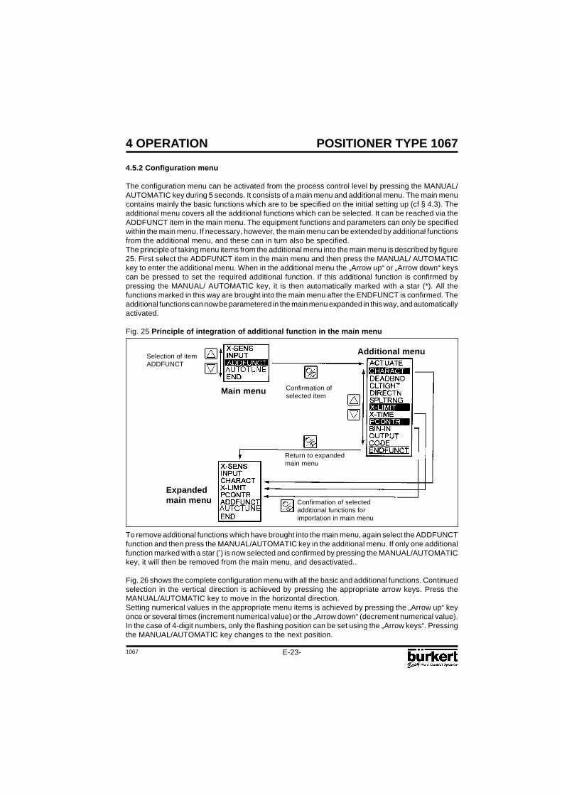
To remove additional functions which have brought into the main menu, again select the ADDFUNCTfunction and then press the MANUAL/AUTOMATIC key in the additional menu. If only one additionalfunction marked with a star (*) is now selected and confirmed by pressing the MANUAL/AUTOMATICkey, it will then be removed from the main menu, and desactivated..
Fig. 26 shows the complete configuration menu with all the basic and additional functions. Continuedselection in the vertical direction is achieved by pressing the appropriate arrow keys. Press theMANUAL/AUTOMATIC key to move in the horizontal direction.Setting numerical values in the appropriate menu items is achieved by pressing the „Arrow up“ keyonce or several times (increment numerical value) or the „Arrow down“ (decrement numerical value).In the case of 4-digit numbers, only the flashing position can be set using the „Arrow keys“. Pressingthe MANUAL/AUTOMATIC key changes to the next position.
4.5.2 Configuration menu
The configuration menu can be activated from the process control level by pressing the MANUAL/AUTOMATIC key during 5 seconds. It consists of a main menu and additional menu. The main menucontains mainly the basic functions which are to be specified on the initial setting up (cf § 4.3). Theadditional menu covers all the additional functions which can be selected. It can be reached via theADDFUNCT item in the main menu. The equipment functions and parameters can only be specifiedwithin the main menu. If necessary, however, the main menu can be extended by additional functionsfrom the additional menu, and these can in turn also be specified.The principle of taking menu items from the additional menu into the main menu is described by figure25. First select the ADDFUNCT item in the main menu and then press the MANUAL/ AUTOMATICkey to enter the additional menu. When in the additional menu the „Arrow up“ or „Arrow down“ keyscan be pressed to set the required additional function. If this additional function is confirmed bypressing the MANUAL/ AUTOMATIC key, it is then automatically marked with a star (*). All thefunctions marked in this way are brought into the main menu after the ENDFUNCT is confirmed. Theadditional functions can now be parametered in the main menu expanded in this way, and automaticallyactivated.
Fig. 25 Principle of integration of additional function in the main menu
Selection of itemADDFUNCT
Additional menu
Expandedmain menu
Return to expandedmain menu
Confirmation of selectedadditional functions forimportation in main menu
Main menu Confirmation ofselected item
E-24-1067
POSITIONER TYPE 10674 OPERATION
Fig. 26 Complete configuration menu
X-SENS DIRECT
LEVER
INPUT 4...20MA
0...20MA
0...10V
ACTUATE
DOUBLE
CHARACT LINEAR
1/25
1/50
25/1
50/1
FREE 0 5 100
DEADBND DBD
CLTIGHT CLT
DIRECTN WPOS
XPOS
END
RISE
FALL
RISE
FALL
SPLTRNG MIN MAX
X-LIMIT X-MIN X-MAX
PCONTRL SETPOINT
PARAM
SCALE
INTERN
EXTERN
KP TN TV X0
X-TIME OPN FAST
OPN SLOW
CLS FAST
CLS SLOW
SINGLE INTERN
BOOST
END
DBD
PV-H SP-L SP-HPV-LDP
BIN-IN INACTIVE
SAFEPOS SPOS NORM OPN
NORM CLS
ADDFUNCT
AUTOTUNE
END A
OUTPUT
BINARY
CODE
ANALOG
NORM CLS
XDXDO NORM OPN
BOOST
CODE MENU+M/A
MENU
1067
POSITIONER TYPE 1067
E-25-
4 OPERATION
4.5.3 Function of keys in the configuration level
Operation of the „Arrow up“ key- Scroll upwards in menu (selection).- Incrementing numerical values in a selected and confirmed menu item.
Operation of the „Arrow down“ key- Scrolling downwards in the menu (selection).- Decrementing numerical values in a selected and confirmed menu item.
Operation of the MANUAL/AUTOMATIC key within the main menu- Confirmation of a selected menu item.- Confirmation of a set value.
Operation of the MANUAL/AUTOMATIC key within the additional menu- Confirmation of a selected menu item of the additional menu for inclusion in the main menu. The
selected menu item is marked with a star (*) in the additional menu. The menu item now appearsin the main menu where it can be selected and manipulated.
- Confirmation of a selected menu item of the additional menu, marked with a star, for deletion fromthe main menu.
4.5.4 Notes on the basic and additional functions
X-SENS (factory setting: DIRECT): Specification of the type of information transfer between thecontinuous action valve (valve setting) and the travel measuring system.Options:
DIRECT: There is a linear relationship between the valve position and the input signal of thepath-measuring system.
Examples:Fitting the positioner to a piston valve (e.g. the Type 2031) and using the external feedback/positionaltransducer (linear potentiometer) to measure the piston position (see section 3.1.2 and Fig. 11).Here, the linear movement of the piston is transformed into a linear movement of the potentiometer.A characteristic correction is therefore not required.Fitting the positioner to a flap valve with part-turn valve actuating drive (e.g. the type 3210) and usingthe internal feedback/positional transducer (rotary potentiometer) to measure the flap position (seesection 3.1.3 and Fig. 15). The rotary movement of the flap is converted into a proportional rotarymovement of the potentiometer. A characteristic correction is not required.
LEVER: There is a sinusoidal relationship between the valve position and the input signal ofthe path-measuring system.
Example:Fitting the positioner to a membrane valve (e.g. the type 265) and using the internal feedback/positional transducer (rotary potentiometer) to measure the valve position (see section 3.1.1 andFig. 7). Coupling is via a lever conforming to NAMUR. The linear movement of the membrane istransformed into a rotary movement of the potentiometer. A sinusoidal curve results. In this option,therefore, the transmission characteristic is linearized internally.
INPUT (factory setting: 4 - 20 mA): Specification of the selected unit signal.Options:
4 - 20 mA: Use of the 4 ... 20 mA unit signal input0 - 20 mA: Use of the 0 ... 20 mA unit signal input0 - 10 V: Use of the 0 ... 10 V unit signal input
E-26-1067
POSITIONER TYPE 1067
ACTUATE (factory setting: SINGLE, INTERN): Method of operation of the valve actuator used.Options:
SINGLE, INTERN: Use of a single acting actuator with intern or without boost valves,SINGLE, BOOST: Use of a single acting actuator with boost valves,DOUBLE: Use of a double acting actuator
4 OPERATION
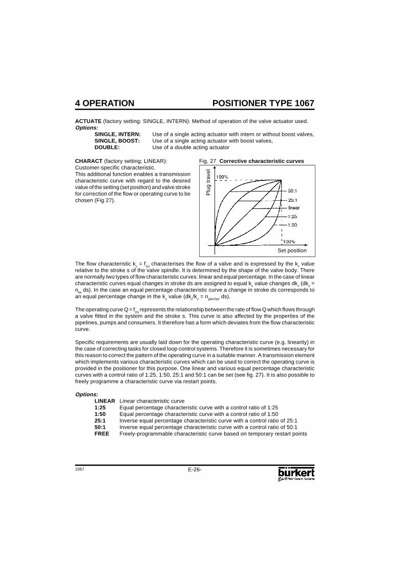
CHARACT (factory setting: LINEAR):Customer-specific characteristic.This additional function enables a transmissioncharacteristic curve with regard to the desiredvalue of the setting (set position) and valve strokefor correction of the flow or operating curve to bechosen (Fig 27).
Fig. 27 Corrective characteristic curves
Set position
Plu
g tr
avel
The flow characteristic kv = f(s) characterises the flow of a valve and is expressed by the kv valuerelative to the stroke s of the valve spindle. It is determined by the shape of the valve body. Thereare normally two types of flow characteristic curves: linear and equal percentage. In the case of linearcharacteristic curves equal changes in stroke ds are assigned to equal kv value changes dkv (dkv =nlin ds). In the case an equal percentage characteristic curve a change in stroke ds corresponds toan equal percentage change in the kv value (dkv/kv = ngleichpr ds).
The operating curve Q = f(s) represents the relationship between the rate of flow Q which flows througha valve fitted in the system and the stroke s. This curve is also affected by the properties of thepipelines, pumps and consumers. It therefore has a form which deviates from the flow characteristiccurve.
Specific requirements are usually laid down for the operating characteristic curve (e.g. linearity) inthe case of correcting tasks for closed loop control systems. Therefore it is sometimes necessary forthis reason to correct the pattern of the operating curve in a suitable manner. A transmission elementwhich implements various characteristic curves which can be used to correct the operating curve isprovided in the positioner for this purpose. One linear and various equal percentage characteristiccurves with a control ratio of 1:25, 1:50, 25:1 and 50:1 can be set (see fig. 27). It is also possible tofreely programme a characteristic curve via restart points.
Options:LINEAR Linear characteristic curve1:25 Equal percentage characteristic curve with a control ratio of 1:251:50 Equal percentage characteristic curve with a control ratio of 1:5025:1 Inverse equal percentage characteristic curve with a control ratio of 25:150:1 Inverse equal percentage characteristic curve with a control ratio of 50:1FREE Freely-programmable characteristic curve based on temporary restart points
1067
POSITIONER TYPE 1067
E-27-
4 OPERATION
Input of the freely-programmable characteristic curve
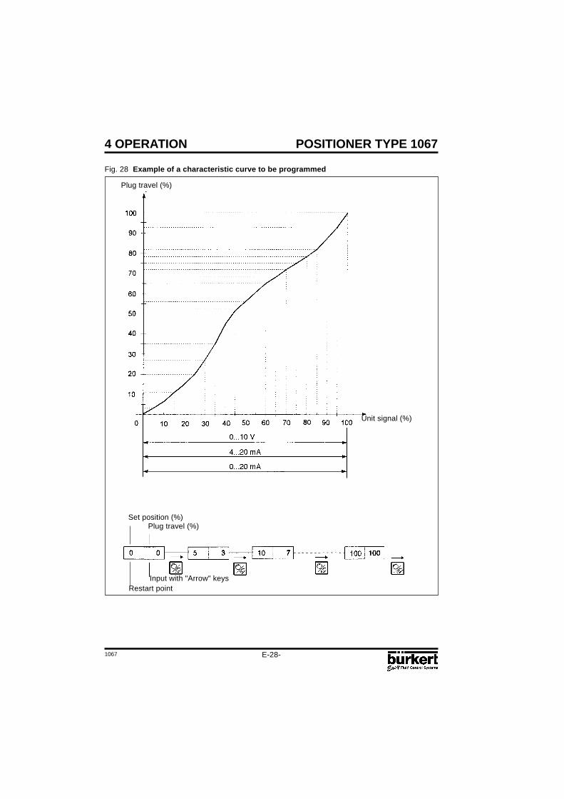
The characteristic curve is defined by means of 21 restart points distributed uniformly over the setpositioning range of 0 ... 100%. These are spaced at 5%. A freely-selectable stroke (range 0 ... 100%)can be assigned to each restart (Fig. 28). The difference between the values of the stroke of twoadjacent restart points shall not exceed 20%.
To input the characteristic curve points (function values), the FREE menu item is first set. Afteroperation of the MANUAL/ AUTOMATIC key the first restart point is input with the display 0 (%). Afterthis the next function value is 0 (%). A function value from 0 to 100% can be set using the arrow keys.After confirmation using the MANUAL/AUTOMATIC key the next restart point is shown on the displayetc. If finally the MANUAL/AUTOMATIC key is pressed to confirm the function value for the last restartpoint (100%), the program switches back to the CHARACT menu item.Fig. 28 demonstrates an example of the free programming of a correction curve.
E-28-1067
POSITIONER TYPE 10674 OPERATION
Fig. 28 Example of a characteristic curve to be programmed
Plug travel (%)
Unit signal (%)
Set position (%)
Restart pointInput with "Arrow" keys
Plug travel (%)
1067
POSITIONER TYPE 1067
E-29-
4 OPERATION
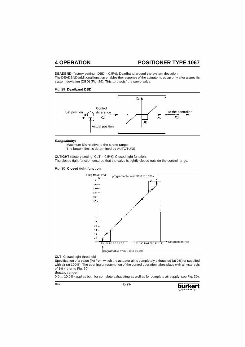
DEADBND (factory setting : DBD = 0.5%): Deadband around the system deviationThe DEADBND additional function enables the response of the actuator to occur only after a specificsystem deviation [DBD] (Fig. 29). This „protects“ the servo valve.
Fig. 29 Deadband DBD
ControldifferenceSet position
Actual position
To the controller
Rangeability:Maximum 5% relative to the stroke range.The bottom limit is determined by AUTOTUNE.
CLTIGHT (factory setting: CLT = 0.5%): Closed tight function.The closed tight function ensures that the valve is tightly closed outside the control range.
Fig. 30 Closed tight function
programable from 0,0 to 10,0%
programable from 90,0 to 100%Plug travel (%)
Set position (%)
CLT: Closed tight thresholdSpecification of a value (%) from which the actuator air is completely exhausted (at 0%) or suppliedwith air (at 100%). The opening or resumption of the control operation takes place with a hysteresisof 1% (refer to Fig. 30).Setting range:0.0 ... 10.0% (applies both for complete exhausting as well as for complete air supply, see Fig. 30).
E-30-1067
POSITIONER TYPE 10674 OPERATION
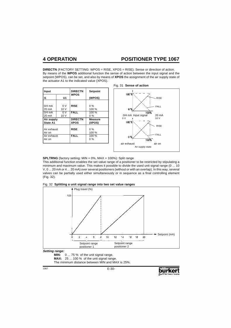
DIRECTN (FACTORY SETTING: WPOS = RISE, XPOS = RISE): Sense or direction of action.By means of the WPOS additional function the sense of action between the input signal and thesetpoint (WPOS). can be set, and also by means of XPOS the assignment of the air supply state ofthe actuator A1 to the indicated value (XPOS).
Setting range:MIN: 0 ... 75 % of the unit signal range,MAX: 25 ... 100 % of the unit signal range.The minimum distance between MIN and MAX is 25%.
SPLTRNG (factory setting: MIN = 0%, MAX = 100%): Split rangeThis additional function enables the set value range of a positioner to be restricted by stipulating aminimum and maximum value. This makes it possible to divide the used unit signal range (0 ... 10V, 0 ... 20 mA or 4 ... 20 mA) over several positioners (without or with an overlap). In this way, severalvalves can be partially used either simultaneously or in sequence as a final controlling element(Fig. 32).
Fig. 32 Splitting a unit signal range into two set value ranges
Setpoint (mA)
Setpoint rangepositioner 1
Setpoint rangepositioner 2
Plug travel (%)
Input DIRECTN SetpointWPOS
I1 U1 (WPOS)
0/4 mA 0 V RISE 0 %20 mA 10 V 100 %0/4 mA 0 V FALL 100 %20 mA 10 V 0 %Air supply DIRECTN MeasureState A1 XPOS (XPOS)
Air exhaust RISE 0 %Air on 100 %Air exhaust FALL 100 %Air on 0 %
Fig. 31 Sense of action
0/4 mA Input signal 20 mA0 V 10 V
air exhaust air onAir supply state
FALL
RISE
FALL
RISE
1067
POSITIONER TYPE 1067
E-31-
4 OPERATION
X-LIMIT (factory setting: XMIN = 0%, XMAX = 100%): Stroke limitation.This additional function enables the (physical) stroke to be limited to a given MIN and MAX percentagevalue (Fig. 33). In the AUTOMATIC mode the stroke range of the limited stroke is then set to equal100%. In the MANUAL mode, on the other hand, the physical stroke is displayed. (It should thereforebe noted that a limited stroke will be displayed differently in the AUTOMATIC and MANUAL modes).
Fig. 33 Stroke limitation
Limited plugtravel (%)
Limited plugtravel (%)
Physical plugtravel (%)
Unlimited plugtravel (%)
Setting range:XMIN: 0 ... 50 % of the total stroke,XMAX: 50 ... 100 % of the total stroke.The minimum distance between XMIN and XMAX is 50%.
OPN FAST (open fast): Opening of the control valve happens with maximal control speed.OPN SLOW (open slow): The maximum setting speed of the control valve is limited duringopening.CLS FAST (close fast): Closing of the control valve happens with maximal control speed.CLS SLOW (close slow): The maximum setting speed is limited when the control valve isclosing.
PCONTRL (process control): Process controller configuration
SETPOINT (factory setting: EXTERNAL): Preset desired value.INTERN: Desired value can be input using the arrow keys (see § 4.4.2).EXTERN: Desired value is preset via the standard signal input.
PARAM: Set parameters for process controller (PID controller)KP: (Proportional correction value or amplification)Range of settings: 0...99.99 (factory setting: 1.00)TN: (reset time)Range of settings: 0.5...999.9 (factory setting: 999.9)
Setpoint (mA)
E-32-1067
POSITIONER TYPE 10674 OPERATION
TV: (rate time)Range of settings: 0.0...999.9 (factory setting: 0)X0: (Operating point of process controller)Range of settings: 0...100% (factory setting: 0%)DBD: No sensibility range of the process controllerRange of settings: 0,2...5% (factory setting: 0,5 %)
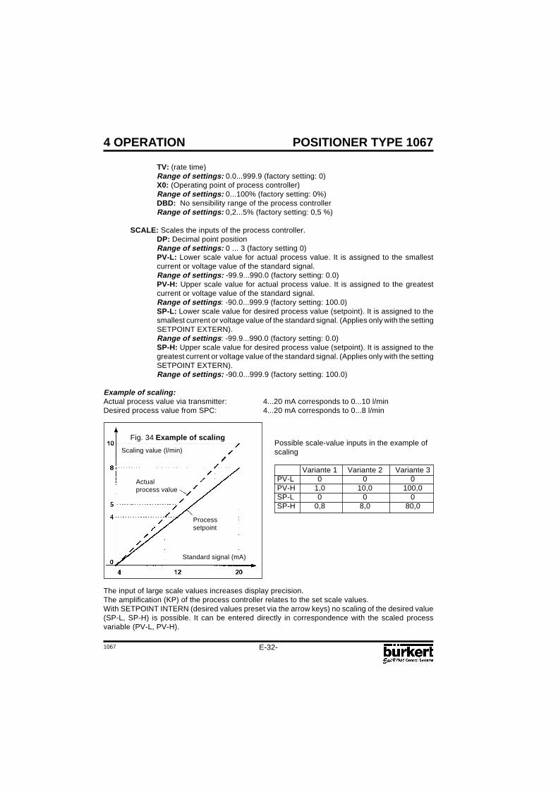
SCALE: Scales the inputs of the process controller.DP: Decimal point positionRange of settings: 0 ... 3 (factory setting 0)PV-L: Lower scale value for actual process value. It is assigned to the smallestcurrent or voltage value of the standard signal.Range of settings: -99.9...990.0 (factory setting: 0.0)PV-H: Upper scale value for actual process value. It is assigned to the greatestcurrent or voltage value of the standard signal.Range of settings: -90.0...999.9 (factory setting: 100.0)SP-L: Lower scale value for desired process value (setpoint). It is assigned to thesmallest current or voltage value of the standard signal. (Applies only with the settingSETPOINT EXTERN).Range of settings: -99.9...990.0 (factory setting: 0.0)SP-H: Upper scale value for desired process value (setpoint). It is assigned to thegreatest current or voltage value of the standard signal. (Applies only with the settingSETPOINT EXTERN).Range of settings: -90.0...999.9 (factory setting: 100.0)
Example of scaling:Actual process value via transmitter: 4...20 mA corresponds to 0...10 l/minDesired process value from SPC: 4...20 mA corresponds to 0...8 l/min
Fig. 34 Example of scaling
Scaling value (l/min)
The input of large scale values increases display precision.The amplification (KP) of the process controller relates to the set scale values.With SETPOINT INTERN (desired values preset via the arrow keys) no scaling of the desired value(SP-L, SP-H) is possible. It can be entered directly in correspondence with the scaled processvariable (PV-L, PV-H).
Standard signal (mA)
Actualprocess value
Processsetpoint
Possible scale-value inputs in the example ofscaling
BIN-IN (factory setting: INACTIVE): Binary input.The action of the binary input (contact) can be specified by means of this additional function.Options:
INACTIVE: Binary input is not active.SAFEPOS (safety position): Input of a safety position SPOS selected if necessary.Setting range: 0 ... 100% of the stroke range (factory setting: SPOS = 0).NORM OPN (normalyl open): Binary input in de-energised position open (normally-opencontact or closer). Safety position is adopted when the contact closes.NORM CLS (normally closed): Binary input in de-energised position closed (normally-closedcontact or opener). Safety position is adopted when the contact opens.
OUTPUT (option): (Additional function only activable with optional board.)- ANALOG Analogic position feedback (4...20 mA) (see Appendix 3)- BINARY Programmable Binary output (see Appendix 4) XDO Alarm deviation value exceeds XD XD Deviation limit value ; Setting range: 0,1 ... 20% (Factory setting 1%) NORM OPN Binary output normally open NORM CLS Binary output normally closed- ALARM Alarm signal, XMIN or XMAX threshold reached XMIN Low alarm limit value ; Setting range: 0...100% NORM OPN Binary output XMIN normally open NORM CLS Binary output XMIN normally closed XMAX High alarm limit value ; Setting range: 0 ... 100% NORM OPN Binary output XMAX normally open NORM CLS Binary output XMAX normally closedBOOST Signal output for external Booster valve (see Appendix 4)
CODE (factory setting: 0000) User code. The positioner can be protected from unauthorised operationby means of a 4-digit user code. 2 Levels of protection are available.MENU+M/A: All functions protected by the user-codeMENU: Access to configuration menu restricted. MANU/AUTO switching and change
of process values are free (cf § 4.4.1).Setting range: 0000 ... 9999
Regardless of the possibility of the existence of a preset code, there is a fixed programmed mastercode which when entered enables all control operations to be performed.
ADDFUNCT (Additional functions): Additional functions.This enables additional functions to be taken into the main menu and then removed (see § 4.5.2).
AUTOTUNE: Automatic parametering.This function enables the program for automatic adaptation of the actuator to the valve in use to bestarted. The following functions are automatically initiated (see section 4.3):- The sensor signal is matched to the (physical) lift of the continuous valve,- The parameters of the PWM signals are determined in order to control the internal magnetic valves,- The parameters of the position controller are adjusted optimally.This automatic setting of parameters is completed in approximately 30-120 seconds.
END: End of configuration menu.(The software version is displayed on the right margin of the display). This menu item enables theconfiguration menu to be left by operation of the MANUAL/AUTOMATIC key (cf § 4.3).
E-34-1067
POSITIONER TYPE 10674 OPERATION
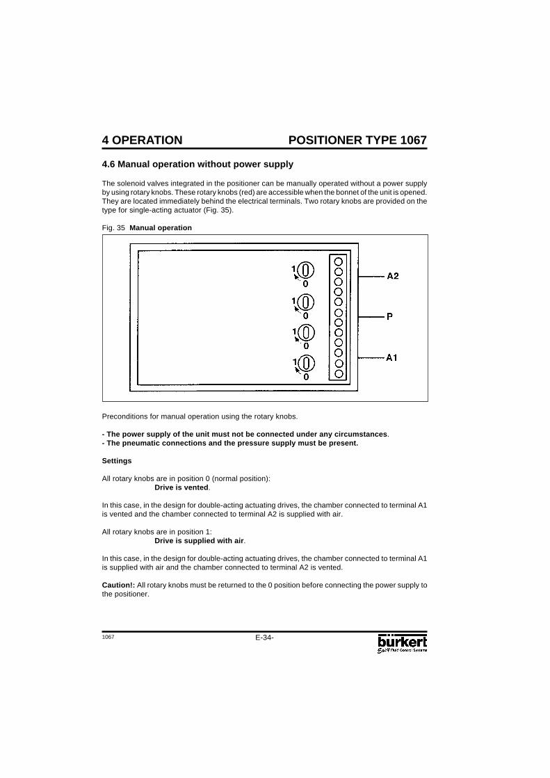
Preconditions for manual operation using the rotary knobs.
- The power supply of the unit must not be connected under any circumstances.- The pneumatic connections and the pressure supply must be present.
Settings
All rotary knobs are in position 0 (normal position):Drive is vented.
In this case, in the design for double-acting actuating drives, the chamber connected to terminal A1is vented and the chamber connected to terminal A2 is supplied with air.
All rotary knobs are in position 1:Drive is supplied with air.
In this case, in the design for double-acting actuating drives, the chamber connected to terminal A1is supplied with air and the chamber connected to terminal A2 is vented.
Caution!: All rotary knobs must be returned to the 0 position before connecting the power supply tothe positioner.
4.6 Manual operation without power supply
The solenoid valves integrated in the positioner can be manually operated without a power supplyby using rotary knobs. These rotary knobs (red) are accessible when the bonnet of the unit is opened.They are located immediately behind the electrical terminals. Two rotary knobs are provided on thetype for single-acting actuator (Fig. 35).
Fig. 35 Manual operation
1067
POSITIONER TYPE 1067
E-35-
4 OPERATION
4.7 Structure of the positioner
Fig. 36 Flowchart of positionertype 1067
Automatic
Manual
E-36-1067
POSITIONER TYPE 1067
Fault messages
Faults during switch on
Message Possible cause Remedy
INT.ERROR Internal fault Not possible, unit defective
Fault messages during AUTOTUNE function
Message Possible cause Remedy
TURN POT Range of the position transducer exceeded Remove the positioner from(only with internal feedback transducer option) the actuator,and turn
the transducer from 180°. cf fig 2.
ERR 2 Actuator not adjustable Fit the positioner withOpening time < 0.5 s bigger air chambers.
Reduce the air pressure
ERR 3 Miscellaneous failures causesManual operation of valve not Check manual actuationin basic setting parametersNo air pressure connected Check compressed air supplyPosition transducer not connected Check the electrical connection
of the transducer;If external position control system only.(cf fig. 3)Check the mechanical couplingof the position controler;if internalposition control system (cf fig. 2)
5 MAINTENANCE
1067
POSITIONER TYPE 1067
E-37-
Y
Xd
Y0
Ymax
Ymin
Xd
Y
APPENDIX
A1: Characteristics of PID controllers
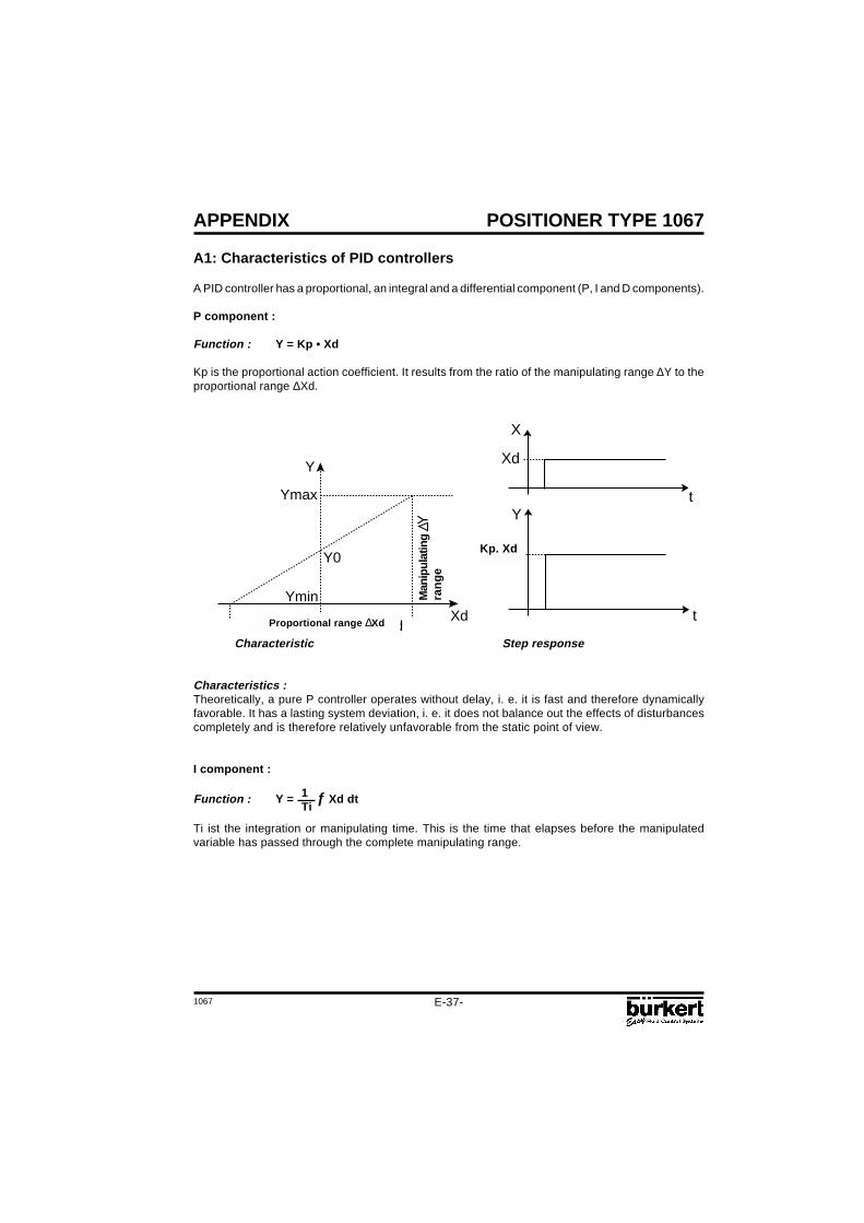
A PID controller has a proportional, an integral and a differential component (P, I and D components).
P component :
Function : Y = Kp • Xd
Kp is the proportional action coefficient. It results from the ratio of the manipulating range ∆Y to theproportional range ∆Xd.
t
t
X
Y
Xd
Kp.XdKp. Xd
1Ti
Characteristic Step response
Characteristics :Theoretically, a pure P controller operates without delay, i. e. it is fast and therefore dynamicallyfavorable. It has a lasting system deviation, i. e. it does not balance out the effects of disturbancescompletely and is therefore relatively unfavorable from the static point of view.
I component :
Function : Y = ƒ Xd dt
Ti ist the integration or manipulating time. This is the time that elapses before the manipulatedvariable has passed through the complete manipulating range.
Man
ipul
atin
gra
ng
e
Proportional range ∆Xd
E-38-1067
POSITIONER TYPE 1067
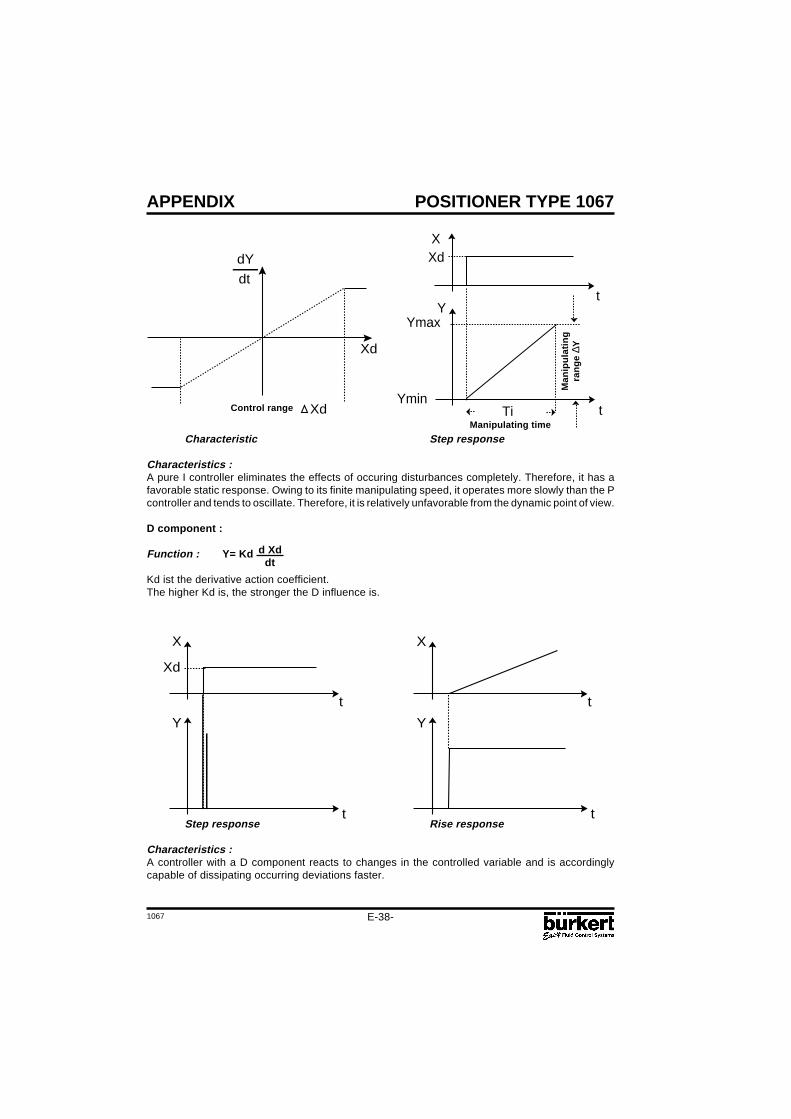
Characteristic Step response
Characteristics :A pure I controller eliminates the effects of occuring disturbances completely. Therefore, it has afavorable static response. Owing to its finite manipulating speed, it operates more slowly than the Pcontroller and tends to oscillate. Therefore, it is relatively unfavorable from the dynamic point of view.
D component :
Function : Y= Kd
Kd ist the derivative action coefficient.The higher Kd is, the stronger the D influence is.
APPENDIX
Xd
Xd
dY
dtt
t
X
Y
Xd
Ymax
YminTi
Step response Rise response
Characteristics :A controller with a D component reacts to changes in the controlled variable and is accordinglycapable of dissipating occurring deviations faster.
t
t
X
Y
Xd
t
t
X
Y
Control range
Man
ipu
lati
ng
ran
ge
∆Y
Manipulating time
d Xddt
1067
POSITIONER TYPE 1067
E-39-
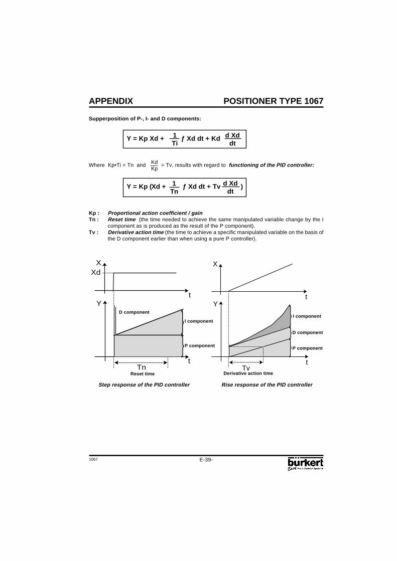
Supperposition of P-, I- and D components:
Y = Kp Xd + ƒ Xd dt + Kd
Where Kp•Ti = Tn and = Tv, results with regard to functioning of the PID controller:
Y = Kp (Xd + ƒ Xd dt + Tv )
Kp : Proportional action coefficient / gainTn : Reset time (the time needed to achieve the same manipulated variable change by the I
component as is produced as the result of the P component).Tv : Derivative action time (the time to achieve a specific manipulated variable on the basis of
the D component earlier than when using a pure P controller).
APPENDIX
1Ti
d Xddt
1Tn
d Xddt
KdKp
t
t
X
Y
TvDerivative action time
D component
I component
P component
t
t
X
Y
Xd
TnReset time
D component
I component
P component
Step response of the PID controller Rise response of the PID controller
E-40-1067
POSITIONER TYPE 1067APPENDIX
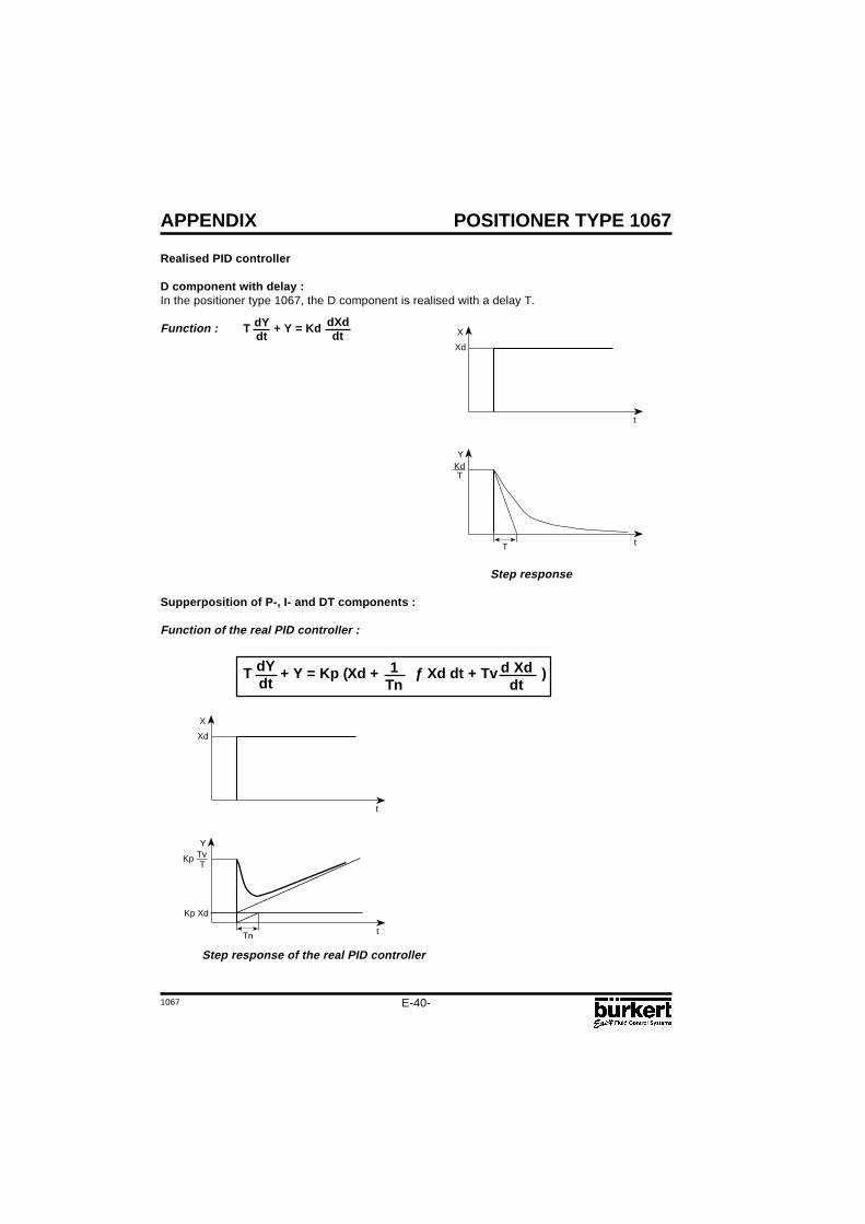
Realised PID controller
D component with delay :In the positioner type 1067, the D component is realised with a delay T.
Function : T + Y = Kd
Step response
Supperposition of P-, I- and DT components :
Function of the real PID controller :
T + Y = Kp (Xd + ƒ Xd dt + Tv )dYdt
1Tn
d Xddt
Step response of the real PID controller
Kp Xd
X
Xd
Y
KpT
t
tTn
Tv
X
Xd
YKdT
t
tT
dYdt
dXddt
1067
POSITIONER TYPE 1067
E-41-
t
X
APPENDIX
Figure : Progression of the control variable at the stability limit
The proportional action coefficient set at the stability limit is referred as Kcrit. The resulting oscillationperiod is referred to as Tcrit.
A2: Rules for adjusting PID controllers
The litterature on control systems specifies a series of adjustment rules with which a favorableadjustment of controller parameters can be achieved experimentally. To avoid bad adjustments, theconditions under which the respective adjustment rules have been elaborated must always beobserved. In addition to the characteristics of the controlled system and of the controller itself, it isimportant to know whether it is intented to balance out a disturbance change or a command variablechange.
Adjustment rules according to Ziegler and Nichols (oscillation method)
When using this method, controller parameters are adjusted on the basis of the control loop'sresponse at the stability limit. In doing so, the controller parameters are adjusted so as to ensure thatthe control loop begins to oscillate. A conclusion as to a favorable adjustment of the controllerparameters is reached from critical characteristic values occurring in this case. It goes without sayingthat, when using this method, it must be possible to bring the control loop to oscillation.
Method:- Set the controller as a P controller (i.e. Tn = 999, Tv = 0), initially selecting a low Kp value.- Set the required setpoint.- Increase Kp until the controlled variable oscillates continuously without attenuation (see following
figure).
Tcrit
Actual value
E-42-1067
POSITIONER TYPE 1067
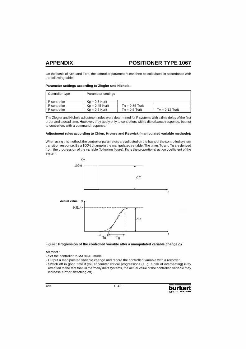
On the basis of Kcrit and Tcrit, the controller parameters can then be calculated in accordance withthe following table:
Parameter settings according to Ziegler und Nichols :
The Ziegler and Nichols adjustment rules were determined for P systems with a time delay of the firstorder and a dead time. However, they apply only to controllers with a disturbance response, but notto controllers with a command response.
Adjustment rules according to Chien, Hrones and Reswick (manipulated variable methode):
When using this method, the controller parameters are adjusted on the basis of the controlled systemtransition response. Be a 100% change in the manipulated variable; The times Tu and Tg are derivedfrom the progression of the variable (following figure). Ks is the proportional action coefficient of thesystem.
APPENDIX
Figure : Progression of the controlled variable after a manipulated variable change ∆Y
Method :- Set the controller to MANUAL mode.- Output a manipulated variable change and record the controlled variable with a recorder.- Switch off in good time if you encounter critical progressions (e. g. a risk of overheating) (Pay
attention to the fact that, in thermally inert systems, the actual value of the controlled variable mayincrease further switching off).
Actual value
t
X
X
Tu Tg
KS. X
t
Y
Y
100%
1067
POSITIONER TYPE 1067
E-43-
APPENDIX
As shown in the figure of the previous page, the proportional action coefficient Ks of the controlsystem can be calculated by way of the increase in the inflectional tangent, i. e. by way of ∆X/∆Y:manipulated variable change)
Ks = ∆X∆Y
The following table lists the settings for the controller parameters depending on Tu, Tg and Ks forcommand and disturbance response and for an aperiodic control operation as well as a controloperation with 20% overshoot. They apply to systems with a P response, with a dead time and witha delay of the 1st order.
Parameter settings according to Chien, Hrones and Reswick :
Parameter settingsControllertype Aperiodic control operation Control operation with
Tn = Tg Tn = 2,4 • Tu Tn = 1,35 • Tg Tn = 2 • TuTv = 0,5 • Tu Tv = 0,42 • Tu Tv = 0,47 • Tu Tv = 0,42 • Tu
TgTu • Ks
TgTu • Ks
TgTu • Ks
TgTu • Ks
TgTu • Ks
TgTu • Ks
TgTu • Ks
TgTu • Ks
TgTu • Ks
TgTu • Ks
TgTu • Ks
TgTu • Ks
E-44-1067
POSITIONER TYPE 1067APPENDIX
A3 : OPTION BOARD "4-20 mA ANALOG POSITION INDICATION"(IDENT. 427193G): MOUNTING AND CONNECTION
The positioner must be equipped with the software version F, or higher. Check it in themain menu, option END: it is displayed at the right-hand side of the screen.
Technical characteristics of the Option output of the positioner- Output signal for the current value : 4-20 mA- External working resistance / Input resistance of a connected device : 0-560 Ohms- Output error rate : < 0,05 %- Potential free output ; electrically separated from the position electronics.
Mounting- Disconnect the positioner from the voltage supply- Unscrew the 4 screws of the positioner cover and open the cover- Remove the 2 red jumpers from the motherboard- Insert the optional board onto the motherboard (see figure below)
Make sure the pins correctly slide into the motherboard.
- Pass the cables through one of the 2 PG9 cable glands, dismantle them over 6 mm andconnect them to the connection block according to the connection schematic (terminals I/O3and I/O4)
- Close the cover and tighten the 4 screws, making sure neither the cables nor the wires arewedged in.
Connection diagram
Configuration- Configurate the positioner as described in chapter 4.5.- Activate the analog position indication by choosing the ANALOG option of the OUTPUT
function
Analog Option board
Motherboardpins
!
!
I1
U1
GND1
I2
GND2
I/O1
I/O2
I/O3
I/O4
PE
+24 V
-
0-10 V0/4-20 mA
4-20 mA
IL = 4-20 mA
RL = 0-560 Ohm
24 V DC Supply Voltage
Analog Option board
Motherboard
+-
1067
POSITIONER TYPE 1067
E-45-
APPENDIX
A4 : OPTION BOARD "BINARY POSITION INDICATION/BOOSTER":MOUNTING AND CONNECTION
- The positioner must be equipped with the software version F, or higher. Check it in themain menu, option END: it is displayed at the right-hand side of the screen.
- For positioners manufactured before 1996 mounting is only possible if themotherboard is fitted with black connection blocks (if not, please contact you nearestBürkert agent).
Technical characteristics
Positioner Relay
- Operating voltage : 24 VDC - Contact type : closed- Electric power consumption : max. 30 W - Commutation current : 0,5 A- Electric connection : screw terminals, - Breaking capacity : 10 W
- Disconnect the positioner from the voltage supply- Unscrew the 4 screws of the positioner cover and open the cover- Remove the 2 red jumpers from the motherboard- Insert the optional board onto the motherboard (see figure below)
Make sure the pins correctly slide into the motherboard.
- Pass the cables through one of the 2 PG9 cable glands and dismantle them over 6 mm.
!
!
Option board
Motherboardpins
E-46-1067
POSITIONER TYPE 1067APPENDIX
Connection
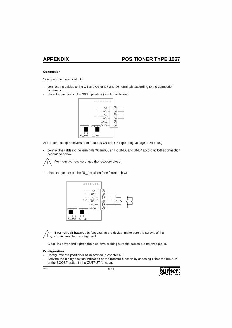
1) As potential free contacts
- connect the cables to the O5 and O6 or O7 and O8 terminals according to the connectionschematic
- place the jumper on the "REL" position (see figure below)
2) For connecting receivers to the outputs O6 and O8 (operating voltage of 24 V DC)
- connect the cables to the terminals O6 and O8 and to GND3 and GND4 according to the connectionschematic below.
For inductive receivers, use the recovery diode.
- place the jumper on the "Uout" position (see figure below)
Short-circuit hazard : before closing the device, make sure the screws of theconnection block are tightend.
- Close the cover and tighten the 4 screws, making sure the cables are not wedged in.
Configuration- Configurate the positioner as described in chapter 4.5.- Activate the binary position indication or the Booster function by choosing either the BINARY