5.2 Project Diagrams and Process Flowsheets ........................................................ 56 5.3 Drawings and Block Flow Diagram .................................................................... 58
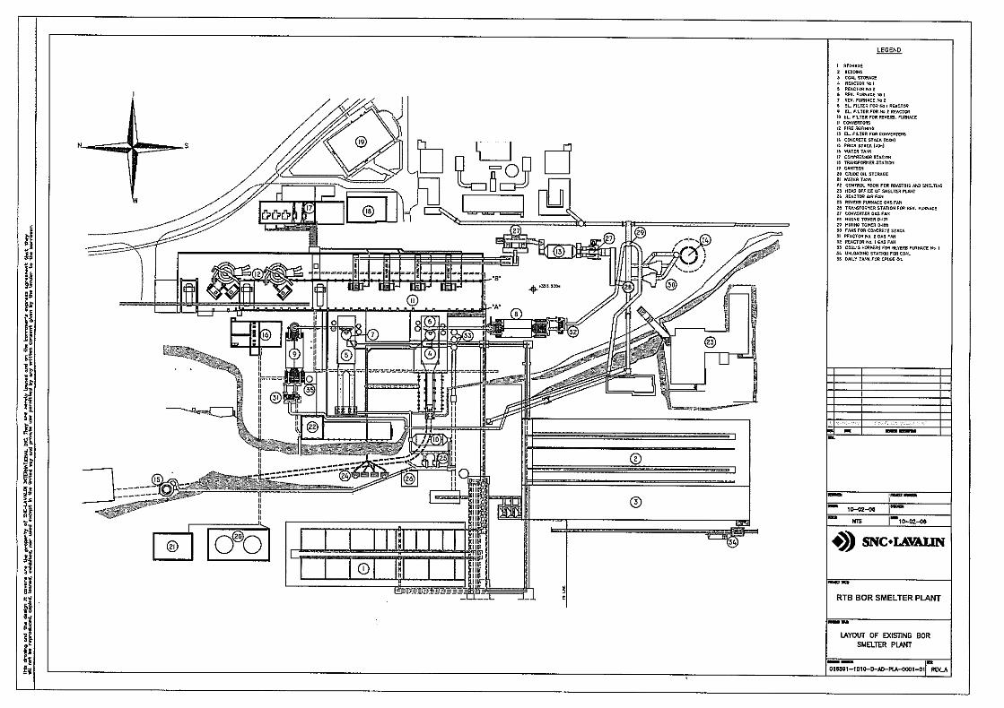
5.3.1 Plant Layout – Existing Plant................................................................. 58 5.3.2 Plant Layout for Base Case. ................................................................. 58
List of Tables
Table 5.1.1 Acidic Waste Water Quality Characteristics............................................... 41
List of Figures
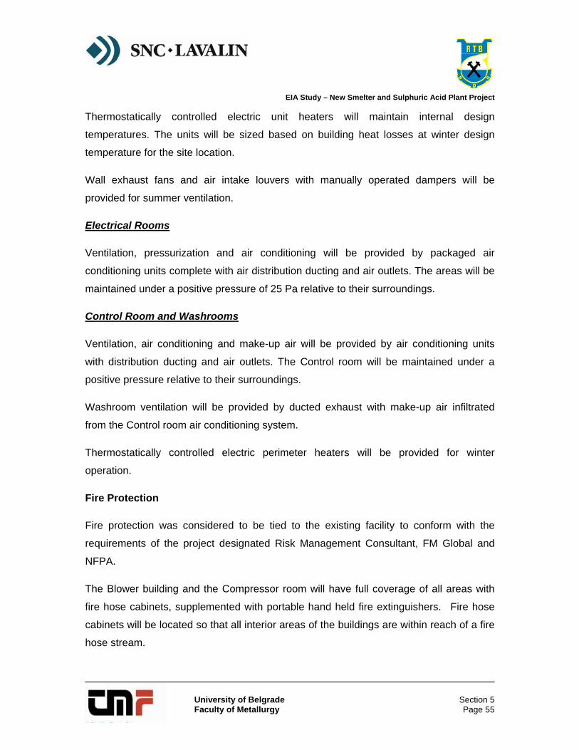
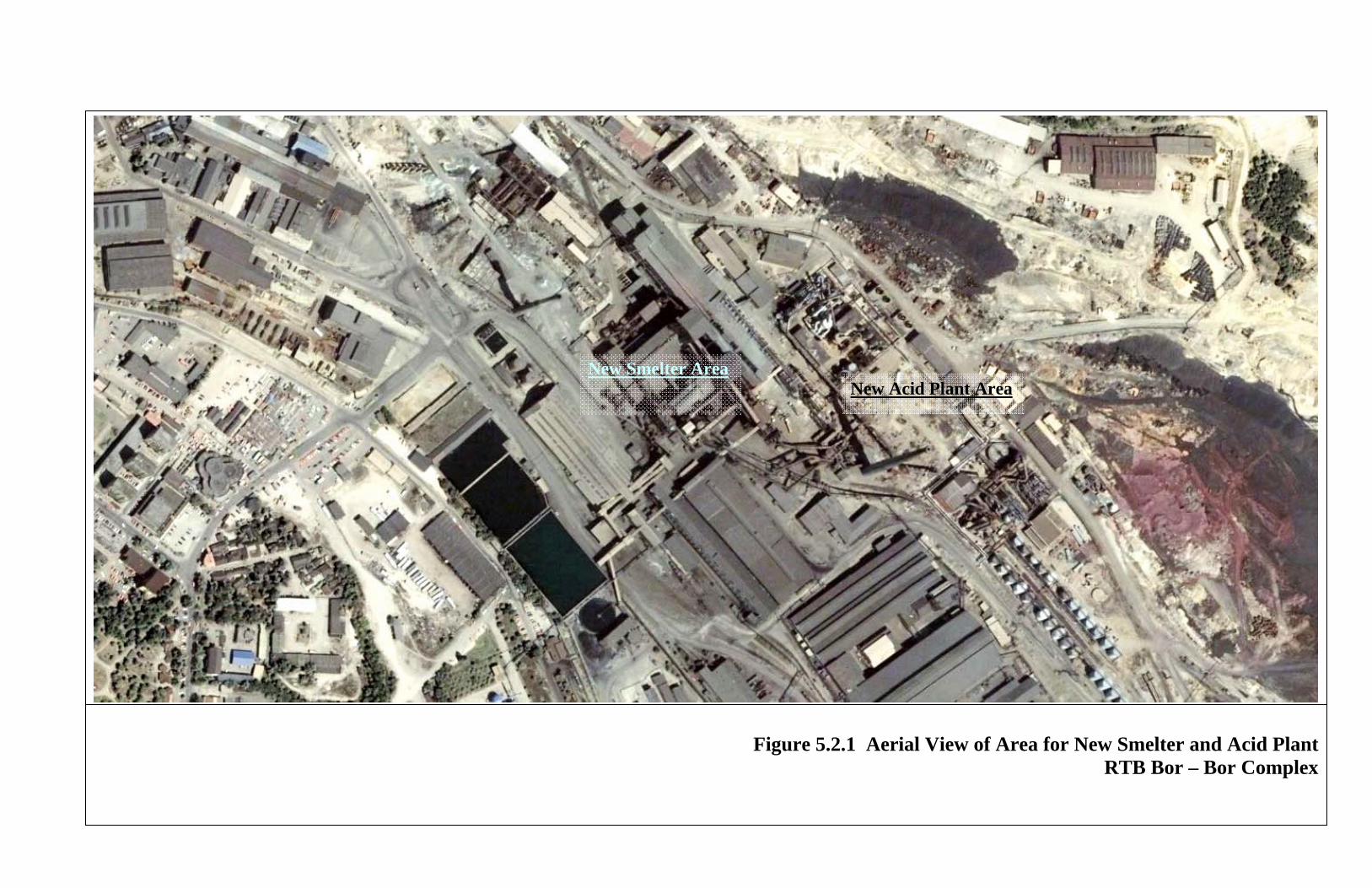
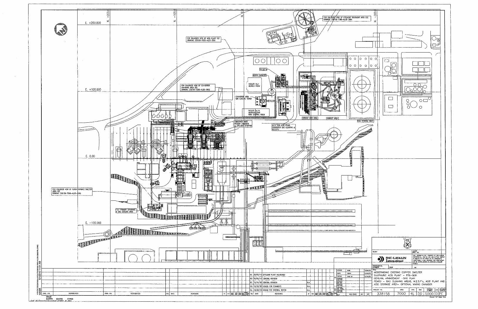
Figure 5.2.1 Aerial View of New Smelter and Acid Plan ............................................... 57
EIA Study – New Smelter and Sulphuric Acid Plant Project
University of Belgrade Faculty of Metallurgy
Section 5
Section 5
Project Description
EIA Study – New Smelter and Sulphuric Acid Plant Project
University of Belgrade Faculty of Metallurgy
Section 5 Page 1
5.0 PROJECT DESCRIPTION
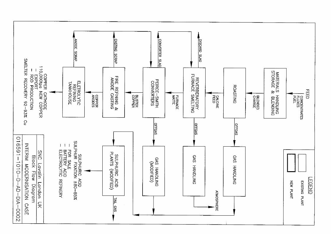
The current smelter modernization project and planned investment scope relates solely to those areas within the Bor smelter and concentrator complex from receipt of road and rail delivered concentrates up to the production of the primary blister copper product and sulphuric acid and steam by-products for export from the complex. Investment in or changes to the existing anode plant and refinery facilities are not included in the current project.
The project is planned to be built on the site of the existing TIR plant and Cadastral parcels in the industrial complex. All works will be carried out within the industrial complex with no expansion of existing boundaries and no temporary engagement of areas not belonging to the smelter.
The new smelter project will involve closure of the old roaster / reverberatory furnace technologies and installation of new primary smelting by FSF technology. The existing copper smelter is to be modified to treat up to 400,000 tpa of copper concentrates using the Outotec FSF technology. The new production capacity will be equivalent to about 80,000 tpa of fine copper.
The modernization will also incorporate the installation of a new modern gas collection for the FSF and a single operating PSC, with sulphur dioxide in the process gases fixed to sulphuric acid in a new sulphuric acid plant.
The new sulphuric acid plant will treat the gases from the new FSF and modernized PSC gas handling operations. Liquid effluent from the smelter wet gas cleaning scrubbers will be treated in an effluent treatment plant.
5.1 Project Facilities
The following discussion provides a detailed description of the following facility components:
• Existing Facilities - General Description & Status;
• Utliities for the Proposed New Smelter and Acid Plant;
• Materials Handling and Blending System;
• Concentrate Drying;
• Flash Smelting Furnace (FSF);
• Peirce-Smith Converter (PSC;
EIA Study – New Smelter and Sulphuric Acid Plant Project
University of Belgrade Faculty of Metallurgy
Section 5 Page 2
• Metallurgical Off-Gas Handling;
• Acid Plant;
• Effluent Treatment;
• Slag Treatment Plant;
• Electrical Supply and Distribution;
• Instrumentation and Controls; and
• Building Services
5.1.1 Existing Facilities General Description
The primary smelting plant uses a process of partial roasting of blended copper concentrate feed to yield a calcine which is fed to a reverberatory smelting furnace (reverb).
While there are two similar lines comprising individual roaster and reverb furnaces, only one line is in operation as there is a shortage of concentrate feed. Over time, the non-operating second line has degraded and been used as a source of parts.
Reverb matte grading around 40% copper is currently processed in a single (hot) operating PSC with a second similar unit available on (cold) standby. Two additional converters are installed but these together with its associated plant have been closed down for many years.
Blister grade copper produced in the batch operated converter is transferred to a single rotary, fire-refining anode furnace for subsequent casting into anodes on a single casting wheel. Anodes are processed to cathode in one of two electrolytic refining tank-houses.
A second casting wheel associated with a further two anode furnaces is also installed but has remained shut down for many years due to the reduced throughput and lack of investment / rehabilitation.
The main (strong) sulphur dioxide-bearing process off gases from the single operating roaster are cooled and partially de-dusted in a hot dry electrostatic precipitator (ESP) prior to ducting and mixing with converter gases.
The converter process gases are collected via a hood and cooled in a water-cooled chamber and prior to partial de-dusting in a single ESP unit. An Induced Draught (ID) fan transfers the converter gas to a mixing chamber where it is combined with the roaster gases.
EIA Study – New Smelter and Sulphuric Acid Plant Project
University of Belgrade Faculty of Metallurgy
Section 5 Page 3
These mixed gases pass to a single operating acid plant (No. 2) for cleaning and cooling prior to conversion and fixation of the contained sulphur dioxide as sulphuric acid.
The main process plant currently in operation was seen to be in a reasonable if run-down condition noting, however, that throughput remains substantially below the original plant capacity of about 125 000 t/y copper. Current copper production is about 40 000 tpa. Reverb gases pass via an ESP and fan system to an independent Reverb stack where they are currently vented to atmosphere without any sulphur fixation.
The second roaster/reverb smelting line is in very poor condition such that substantial refurbishment and major investment would be required if it were ever intended to restart.
With regard to the gas treatment aspects, the No. 1 acid plant, which is of similar design and capacity to the currently operating No. 2 acid plant, is in a state of major disrepair and has been substantially cannibalised to maintain operation of the No. 2 plant.
A more modern and approximately of 50% larger capacity No.3 acid plant is also in a state of major disrepair and its refurbishment is not considered economically viable.
5.1.2 Utilities
Process Description
Plant Air and Instrument Air
Plant air and instrument air will be provided by existing plant and equipment.
Air receivers will be installed as necessary to maintain integrity of supply e.g. high pressure atomising air supply to the PSC evaporative cooling chamber water sprays.
Plant Water
The existing river water supply will provide plant water and will be treated as necessary to produce potable water and demineralised water using existing facilities.
Potable Water
Potable water will be used for emergency showers, eyewash and ablution facilities.
Demineralised Water
The existing smelter demineralised water plant will provide demineralised water for boiler feed water.
EIA Study – New Smelter and Sulphuric Acid Plant Project
University of Belgrade Faculty of Metallurgy
Section 5 Page 4
Steam (New)
Saturated high-pressure steam (6 MPa) will be provided by the FSF waste heat boiler.
Saturated low-pressure steam (2 MPa) will be provided by the sulphuric acid plant heat recovery system.
Oxygen Supply (New)
An over-the-fence oxygen supply will be required and must be capable of supplying 10,000 Nm3/h of technical oxygen at 150 kPa(g) during normal operation.
The major portion of this oxygen will be required for enrichment of the FSF process air during operation. In addition, a smaller portion of high pressure oxygen at 1,500 kPa(g) will be required for matte and slag tapping of the furnace.
A further portion of the oxygen will be required for blowing enriched air on both slag and copper blow stages of the PSC operation.
Oxygen of minimum purity of 95% O2 by volume will be required.
Equipment Description
Water Treatment, Water and Fire Water
Branches from relevant water tie-in points will run to delivery points in the following areas:
• Plant water for new conveying system for blending beds: wet concentrate feed system areas: slag cooling water tank;
• Firemain water for new conveying system for blending beds and wet concentrate feed system areas;
• Demineralised water for PSC primary cooling water system jacket cooling water tank; and
• Demineralised water to PSC Nº3 and Nº4 spray water tanks;
• No provision for secondary cooling water pipes has been made for this area.
EIA Study – New Smelter and Sulphuric Acid Plant Project
University of Belgrade Faculty of Metallurgy
Section 5 Page 5
Oxygen Distribution
A pipe rack for low and high pressure oxygen will run from tie-in points at the over-the-fence oxygen plant to delivery points in the FSF area for low pressure oxygen (40 kPa) and high pressure oxygen (1,500 kPa), and additionally for low pressure oxygen (150 kPa) to a tie-in point with low pressure blast air ducts for PSC converter Nº3 and Nº4.
Air Supply and Distribution
Branches for plant and instrument air from the relevant tie-in points will run to delivery points in the following areas:
• Plant and instrument for new conveying system for blending beds and wet concentrate feed system areas;
• Plant air for spray cooling system air receivers in cooling chamber;
• Instrument air for valves in converter gas handling system; and
• Plant and instrument air for slag cooling pits.
Steam and Condensate Handling and Distribution
No provision has been made for steam and condensate distribution.
Fuel Storage and Distribution
No provision has been made for heavy fuel oil and diesel storage and distribution.
5.1.3 Material Handling and Blending
Process Description
Material Off-Loading (Existing)
Concentrates containing typically 10% moisture and fluxes delivered by rail will be off-loaded using a rail tippler of 40t capacity. A weigh scale is under-fitted to the discharge belt conveyor.
A ground hopper will be used for receiving concentrates and fluxes delivered by road. The ground hopper is suitable for both end and side-tipping vehicles.
A weighbridge, remote from the ground hopper, is situated adjacent to the smelter site entrance for weighing road deliveries.
EIA Study – New Smelter and Sulphuric Acid Plant Project
University of Belgrade Faculty of Metallurgy
Section 5 Page 6
Material Storage (Existing)
After off-loading, materials will be transferred by a series of conveyors and discharged into concrete bunkers in a covered storage area. Each concentrate type can be stored in discrete stockpiles for subsequent reclaim. Up to 30 750t of concentrate will be stored in this area.
Up to 3 520t of silica flux will also be stored in the covered storage area.
Concentrates and fluxes will discharge onto a material transfer conveyor.
Charge Blending (Existing)
The material transfer conveyor will transport the charge materials to the blending beds tripper conveyor where they will be discharged along the length of the bed to promote homogeneity of the FSF charge.
There will be two blending beds, each of nominal capacity 12 000t, equivalent to about ten days’ supply at the nominal smelting rate. One bed will be built up while the other bed is in the process of being drawn down, providing the charge for the FSF.
Material Transfer
Material will be reclaimed from the blending beds by means of an existing front end loader. The front end loader will discharge the blend via an existing single hopper onto the blending beds existing reclaim conveyor. The blended concentrates will be transferred by a series of existing conveyors to a new diverter which directs the feed a new reversible conveyor that will feed three new day bins, two for storing blended furnace feed, each of capacity 400t, and one 40t capacity for storing flux.
The concentrates and fluxes will be drawn from the day bins using weigh feeders, at prescribed rates, and fed via a new feed belt conveyor to a steam dryer.
Equipment Description
Concentrate and Silica Blend Conveying
Blended copper concentrate will be transferred from the blending beds to blended concentrate bins using existing front end loaders and hopper / feeders as reclaiming units. Existing belt conveyors 1036, 1037 and 1038 will be used to transfer blend concentrate to day bins via a new diverter chute in the existing transferring tower. Three new belt conveyors will transfer the material to the feed day bins. Belt conveyor parallel to existing conveyor 1039 will run from the diverter chute to a new belt conveyor in a 90º
EIA Study – New Smelter and Sulphuric Acid Plant Project
University of Belgrade Faculty of Metallurgy
Section 5 Page 7
arrangement to deliver the material to a reversible belt conveyor which feed both blended concentrate day bins.
Blended concentrate conveying capacity will be 240 t/h.
Silica flux will be transferred from the material storage building using existing reclaimers. Existing belt conveyors will be used to transfer silica flux to day bins via a new diverter chute in the existing transferring tower. A belt conveyor will run from the diverter chute to a silica trimming bin.
Silica flux conveying capacity will be 150 t/h.
Blended Concentrate and Trimming Silica Blend Storage
Two day bins for blended concentrate storage and one day bin for trimming silica flux storage will be provided.
Each bin will be equipped with bar and knife valves.
Blended concentrate day bins will be 400t each and the Silica flux day bin 40t.
Wet Concentrate Feed System
Three belt feeders fitted with belt scales will draw blended concentrate and silica flux from the day bins.
Blended concentrate belt feeders will be treated at 80 t/h each and the Silica flux belt feeder 5 t/h.
Feed materials from the belt feeders will be collected on the inclined belt conveyor and delivered to vibrating screen, for lump removal in the feed.
Lumps will be collected in a tote bin and will be recycled to the blending plant. Screen undersize material will be transferred by a series of two belt conveyors arranged and a pipe conveyor which will feed the steam dryer feed belt conveyor.
Vibrating screen and steam dryer feed conveying system rating will be 80 t/h.
5.1.4 Concentrate Drying
Process Description
The drying process will comprise a single rotary steam dryer for indirect heating using saturated steam of feed that contains approximately 10% moisture. The FSF blended
EIA Study – New Smelter and Sulphuric Acid Plant Project
University of Belgrade Faculty of Metallurgy
Section 5 Page 8
feed mixture from the raw materials handling area will be dried to less than 0.3% free moisture by weight.
Steam at about 2 MPa pressure and 212oC will flow through steam heating elements and condense on the inner surface. The heat released will be conducted through the element wall and into the wet feed mixture bed.
As the temperature of the wet material rises, moisture will vaporise, diffuse through the material bed and evaporate into the dryer freeboard. The driving force of this phenomenon is the vapour pressure gradient, firstly inside the material bed and secondly, between the material bed and the ambient air.
The humid air will be continuously drawn from the dryer and be discharged to atmosphere through the gas collection system. Gas collection will consist of a bag filter and exhaust fan. The exhaust fan will be equipped with a variable speed drive for draught control.
Description
The dryer will use indirect heating by medium pressure saturated steam as the energy source. The steam manifold will be located at the end of the dryer. From the manifold steam will be divided into several steam-pipe heating elements located in the direction of the drum axis.
The whole steam-pipe heating element system will rotate along with the dryer shell. The elements will be designed to allow the steam to flow freely in the pipes and the condensed water will be collected in the manifold. The condensate will be removed via a siphon pipe through the rotary joint.
The dryer will be supported by two riding rings, each rolling on support rollers. The drum will be slightly tilted downwards and thrust rollers will be installed to prevent the drum creeping off the support rollers.
The feed-hole, located in the centre of the feed-plate, will allow the belt feeder to bring the wet feed mixture into the dryer and also allows the entry of purge air that will remove the evaporated moisture. At the discharge end there will be a weir plate that allows the dry product to flow out of the drum and will control drum filling.
The shell of the dryer will be made from mild steel plate. The inside of the drum will be lined with a stainless steel plate to prevent corrosion and moist concentrate sticking to the shell.
At the discharge end, the warm air carrying the vaporized water and a small amount of dust will be drawn from the drum by an exhaust fan via a bag filter to stack. The new
EIA Study – New Smelter and Sulphuric Acid Plant Project
University of Belgrade Faculty of Metallurgy
Section 5 Page 9
purge air flowing into the dryer through the feed-end hole continuously replaces the removed air.
The dryer product together with dust collected in the bag filter will be stored in a dried FSF blended feed bin below the steam dryer.
The dried product will be discharged into a pneumatic conveyor tank and be conveyed by means of two parallel dense-phase pneumatic conveyors to a FSF feed bin located above the FSF loss-in-weight feed system.
Normally, both pneumatic conveyors will operate. Dry compressed air will be used for conveying.
The FSF feed bin will be equipped with a bag filter for cleaning the conveying air and a fan for exhausting it to atmosphere.
5.1.5 Flash Smelting Furnace (FSF)
Process Description
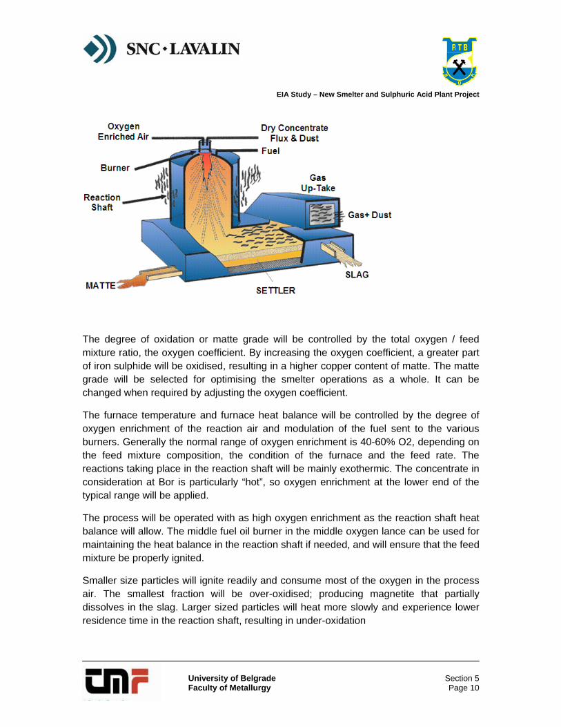
The dry charge mixture, together with the oxygen-enriched process air, will form a homogeneous suspension that reacts in the reaction shaft. The suspension heats up, ignites and burns rapidly to form a matte and slag in the settler.
The main shaft reactions that will occur are:
4CuFeS2 + 61/2O2 = (2Cu2S + FeS) + 3FeO + 5SO2
2FeS2 + 5O2 = 2FeO + 4SO2
Corresponding reaction equations can be written for the other sulphide minerals that form the concentrate mixture. These oxidation reactions will produce energy for smelting the reaction products.
EIA Study – New Smelter and Sulphuric Acid Plant Project
University of Belgrade Faculty of Metallurgy
Section 5 Page 10
The degree of oxidation or matte grade will be controlled by the total oxygen / feed mixture ratio, the oxygen coefficient. By increasing the oxygen coefficient, a greater part of iron sulphide will be oxidised, resulting in a higher copper content of matte. The matte grade will be selected for optimising the smelter operations as a whole. It can be changed when required by adjusting the oxygen coefficient.
The furnace temperature and furnace heat balance will be controlled by the degree of oxygen enrichment of the reaction air and modulation of the fuel sent to the various burners. Generally the normal range of oxygen enrichment is 40-60% O2, depending on the feed mixture composition, the condition of the furnace and the feed rate. The reactions taking place in the reaction shaft will be mainly exothermic. The concentrate in consideration at Bor is particularly “hot”, so oxygen enrichment at the lower end of the typical range will be applied.
The process will be operated with as high oxygen enrichment as the reaction shaft heat balance will allow. The middle fuel oil burner in the middle oxygen lance can be used for maintaining the heat balance in the reaction shaft if needed, and will ensure that the feed mixture be properly ignited.
Smaller size particles will ignite readily and consume most of the oxygen in the process air. The smallest fraction will be over-oxidised; producing magnetite that partially dissolves in the slag. Larger sized particles will heat more slowly and experience lower residence time in the reaction shaft, resulting in under-oxidation
EIA Study – New Smelter and Sulphuric Acid Plant Project
University of Belgrade Faculty of Metallurgy
Section 5 Page 11
In the settler, the molten as well as solid smelting products will separate from the gas stream. The reactions will still continue in the bath below the reaction shaft when the over and under-oxidised particles react with each other producing matte, slag and sulphur dioxide gas.
The slag forming reactions between the oxidic reaction products and silica flux will be completed in the bath. The main reactions will be as follows:
2FeO + SiO2 = 2FeO.SiO2 (fayalite).
Because matte and slag are insoluble in each other, they separate in the furnace settler. The matte droplets will be denser than slag and settle by gravity through the slag to form a distinct layer on the furnace bottom. The less dense slag layer will float on the matte layer.
Some technical oxygen will be blown into the settler, close to the uptake shaft, to ensure flue dust post-combustion and sulphatizing reactions proceed. There will be five nozzles to distribute and mix the technical oxygen evenly to the furnace off-gas. Flue dust sulphatizing reactions will be completed in the waste heat boiler by the sulphatizing air feed. Burners are also present in the settler to maintain the settler heat balance.
A matte grade of 62% Cu has been selected, but can be adjusted based on operational requirements. The main factors affecting the selection of matte grade will be:
• Raw materials;
• Converting capacity;
• Volumetric capacity of acid plant; and
• Oxygen plant capacity.
Equipment Description
FSF Feed Systems
The gravimetric feed systems for the FSF feed (concentrate and silica flux) and flue dust will consist of the following:
• A material fluidisation cone at the feed mixture / dust bin bottom hopper;
• Slide gate valve;
• Dome valve;
EIA Study – New Smelter and Sulphuric Acid Plant Project
University of Belgrade Faculty of Metallurgy
Section 5 Page 12
• Dosing bin;
• Agitators;
• Screw feeder; and
• Bin venting system.
The bottom cone of the bin will be provided with aeration nozzles to fluidise the material to aid discharge.
The feed mixture bin and the dosing bin are provided with load cells. The dosing bin is filled batch-wise with a dome valve.
The dried feed mixture is fed from the dosing bin to an air slide conveyor via a screw feeder.
The FSF feed systems consist of gravimetric loss-in-weight feeders for both the feed mixture and recycled flue dust.
The concentrate will be fed from the dosing bin to the concentrate burner via the screw feeder system and the air slide conveyor.
The operation of the gravimetric feed system will be based on the continuous weighing of the material in the dosing bin, calculation of the actual feed rate and control of the rate according to a set point by the speed of the screw feeder. The dosing bin will be filled batch-wise and the screw feeder speed programme-controlled. The dosing bin outlet will be provided with agitators to fluidise the material and provide constant feeding.
The dosing bin aeration will be carried out with the venting duct and valve system. One valve will be open during normal feeding (dosing bin emptying) to let the compensation air flow into the dosing bin for accurate weighing. The other valve will be opened during the dosing bin filling period to let the exhaust air flow into the feed mixture bin.
The exhaust gas from the bin will be cleaned in a bag filter and blown to atmosphere by an air fan.
The air slide conveyor for the furnace dry charge mixture will be a slightly downwards-tilted air-assisted gravity conveyor using dried plant air.
Flue Dust Feed to FSF
Flue dusts from the FSF off-gas handling will be re-circulated back to the process via a separate FSF flue dust feed system. Recycled flue dust will be pneumatically conveyed
EIA Study – New Smelter and Sulphuric Acid Plant Project
University of Belgrade Faculty of Metallurgy
Section 5 Page 13
into the dust bin by dense phase pneumatic conveyors. An equivalent loss-in-weight feed system will weigh the flue dust and convey it to a slide conveyor.
The gravimetric system for flue dust corresponds to that of the dried feed mixture with dosing and screw feeder. The screw feeder will feed the flue dust to a draglink conveyor which will convey the total FSF charge to a concentrate burner located in the centre of the reaction shaft roof.
Concentrate Burner
The concentrate burner will be provided with a central jet distributor for distributing the dry charge and oxygen enriched process air as an even suspension into the reaction shaft. The spread of the air-concentrate suspension will be controlled by adjusting the flow rate of the suspension air. Plant air will be used to supply the distribution air for the central jet distributor. The distribution air will cool the jet distributor; the shell around the jet distributor will be water-cooled.
Oxygen-enriched process air will be blown into the air chamber of the concentrate burner. Process air velocity will be controlled at the air chamber discharge opening. A part of the oxygen demand for smelting, referred to as middle oxygen, will be fed as technical oxygen through the middle lance of the central jet distributor. The middle oxygen lance will be used to control the smelting reactions in the middle zone of the reaction shaft.
The concentrate burner will be equipped with step-less process air velocity control to maintain the required process air velocity at the air chamber discharge opening, over the range of operating conditions.
In the central jet distributor a fuel oil lance will provide additional heat to the concentrate suspension. The middle fuel will be burned with technical oxygen emanating from the middle oxygen lance.
Flash Smelting Furnace Structure
The FSF consists of three main sections: a vertical reaction shaft; a horizontal settler; and a vertical uptake shaft.
The reaction shaft is a refractory-lined cylindrical-shaped tower suspended from a rigid furnace steel frame. The refractory lining will be thermally protected with copper cooling elements installed between the brick layers.
The main smelting reactions take place in the reaction shaft. Molten products and off-gas are then led to the horizontal settler.
EIA Study – New Smelter and Sulphuric Acid Plant Project
University of Belgrade Faculty of Metallurgy
Section 5 Page 14
The settler is a rectangular, refractory-lined vessel. The steel casing will be retained by vertical buck-stays and horizontal beams that surround the casing and will be connected to each other by spring-loaded tie-rods. The structure will allow thermal movements during heating and cooling against preset inward-force spring loads.
Copper cooling elements will be used to cool the refractory lining of the settler walls and part of the settler roof. In the furnace settler, matte and slag layers will be formed that separate into two distinct layers. The process off-gas is conducted to the uptake shaft.
The uptake shaft is a vertical, refractory-lined cylindrical structure at the opposite end of the settler. The uptake shaft will be suspended from the rigid steel frame surrounding the furnace. The connections between the settler and uptake shaft, as well as the uptake shaft and waste heat boiler, will be cooled by copper cooling elements. The dust-containing off-gas will be conducted via the uptake shaft to the waste heat boiler.
Matte and Slag Tap Holes
Matte tap holes will be located at the sidewall and reaction shaft end wall of the settler. The tap holes will be equipped with water cooled copper plates. The holes will be opened manually using oxygen lances and closed with clay cones / stoppers.
Matte will be periodically tapped through the tap holes and laundered to ladles for transfer by aisle crane to PSCs. The matte launders will be constructed of steel plate and lined with refractory.
Slag will be tapped through the tap holes at the uptake end of the settler. The tap holes will be equipped with water-cooled copper plates. The tap holes will be opened manually using oxygen lances and closed with clay cones / stoppers.
Slag will be laundered to dedicated slag ladles that will be transferred to the slag cooling area by carrier. The slag launders will be constructed from water cooled copper.
FSF Burners
The settler will be provided with four roof- and six wall- fuel-oil burners. Each settler burner will have a design capacity of 300kg/h of fuel oil.
Auxiliary fuel oil burners will be available to ensure the furnace heat balance. Product target temperatures will be maintained during normal operation and also during feed interruptions or during heat up of the furnace after relining.
Because of the batch nature of the PSC operations, FSF matte tapping will be intermittent. Fuel oil burners will be provided for the matte launders to maintain launder temperature and aid matte flow.
EIA Study – New Smelter and Sulphuric Acid Plant Project
University of Belgrade Faculty of Metallurgy
Section 5 Page 15
Process Air and Combustion Air Fans
Two process air fans will supply process air to the concentrate burner, one in operation and one on standby. Two combustion air fans will supply combustion air to the fuel burners and sulphatising air to the waste heat boiler.
Each fan will be provided with inlet guide vanes and be equipped with frequency converter drives. The combustion air fans will be also connected to emergency power.
FSF Cooling Water System
The FSF will consist of a primary closed-circuit cooling-water system. The heat from this circuit will be removed in plate heat exchangers that will be cooled by secondary cooling water. The secondary cooling water will be cooled open-circuit in a cooling tower(s).
Primary Cooling Water System
The primary cooling water system will comprise: jacket cooling water tank; circulation pumps; heat exchangers; supply lines with distribution headers; collection headers; and return lines.
Primary cooling water will pumped from the jacket cooling water tank via plate heat exchangers and through cooling water headers to the FSF cooling elements.
There will be three electric jacket cooling water pumps; two will normally be in operation at any one time. There will be two standby diesel pumps. The electric pumps will be connected to the emergency power supply. In case of a power failure, emergency power will be connected automatically in about 20 seconds. If the emergency power cannot be started within about 2 minutes, the diesel pumps will be started automatically.
FSF cooling elements will be fitted at various locations in the brick lining. Water cooled copper blocks are situated at the following locations:
• Reaction shaft walls;
• Settler walls and roof;
• Settler and reaction shaft junction;
• Settler and uptake shaft junction; and
• Uptake shaft and waste heat boiler junction.
EIA Study – New Smelter and Sulphuric Acid Plant Project
University of Belgrade Faculty of Metallurgy
Section 5 Page 16
Tap-hole blocks and slag launders will also be of water-cooled copper construction. The concentrate burner cooling water supply will also be connected to the furnace closed-circuit cooling-water system.
Warmed cooling water from the cooling elements and other water cooled equipment will be conducted to the collection headers and jacket cooling water tank for re-circulation. A small bleed / make-up will be needed to maintain cooling-water quality in the primary cooling water circuit.
All electric primary circuit cooling-water pumps will be connected to the smelter emergency power system.
5.1.6 Peirce-Smith Converter (PSC)
Process Description
Converter Operation
There will be two PSCs with nominal capacity 120t of blister copper. One converter will be hot and in operation at any one time with the second unit on cold standby / maintenance. There will be up to three converter charges (batches) per day producing a blister copper for subsequent fire refining in anode furnaces.
About 160t of FSF matte will be ladled on demand to form each converter charge in a series of slag blows. There will be up to five slag blows before the final slag skim. The slag bowing will be followed by copper blows which are essentially continuous except for short interruptions to add copper scrap coolant.
The typical blowing rate on slag and copper blows will be 33,000 Nm3/h and 36,000 Nm3/h respectively. Oxygen enrichment of the blast air typically will be 26% on a slag blow and 22.5% on a copper blow.
Silica flux will be added to form a low melting point liquid fayalite type slag with FeO and Fe3O4. Silica will be stored in a bin adjacent to the converter hood; the fluxing rate will be nominally 1t per minute for blows other than the first when “bank” flux is being consumed.
Temperature control during a slag blow will be effected by the addition of reverts. This is important for both bath temperature control and maximising production and recovery by the recycling of secondary materials. Crushed reverts will be stored in a bin adjacent to the silica flux bin and will be charged via the flux charging system.
The converter is skimmed clean of slag as far as possible when almost all the FeS has been converted to iron oxide. The slag will be discharged into aisle ladles transferred by
EIA Study – New Smelter and Sulphuric Acid Plant Project
University of Belgrade Faculty of Metallurgy
Section 5 Page 17
electric (EOT) overhead travelling cranes and then decanted into new large transfer ladles that will be despatched by mobile slag carrier to the slag cooling area. Any matte that has settled out of this slag is not added to the transfer ladles but will be returned to the converter.
The rate of temperature rise during a copper blow will be only about one third of that on a slag blow; however, the temperature rise is sufficient to require cooling by the addition of recycled solid copper such as anode casting scrap and refinery tank house scrap anode returns.
At the completion of the copper blow the blister copper produced will be low in sulphur and oxygen: generally within the ranges 10-300 ppm sulphur and 1,000-8,000 ppm oxygen. It will be transferred by EOT crane to the existing anode fire-refining furnaces.
As a second converter is not available to receive the final slag, and the copper content is too high to send it to the transfer ladle, the converter will have to be “banked” so that the blister can be removed from under the slag, ad the slag left in the vessel as a heel for the following charge. Banking is achieved by adding coarse flux adjacent to the mouth of the converter when it is in the skim position to solidify a “bank” of slag that act as an underflow weir for blister. The bank, which is high silica, is well preheated so the coarse flux is readily taken into the slag during the first slag blow of the following charge.
Equipment Description
No physical modifications to the converters themselves are planned except for minor improvements related to improving labyrinth-type sealing at the hood to apron plate interface. The operating cycle will change due to the higher matte grade.
5.1.7 Metallurgical Off-Gas Handling
Process Description
FSF Off-Gas System
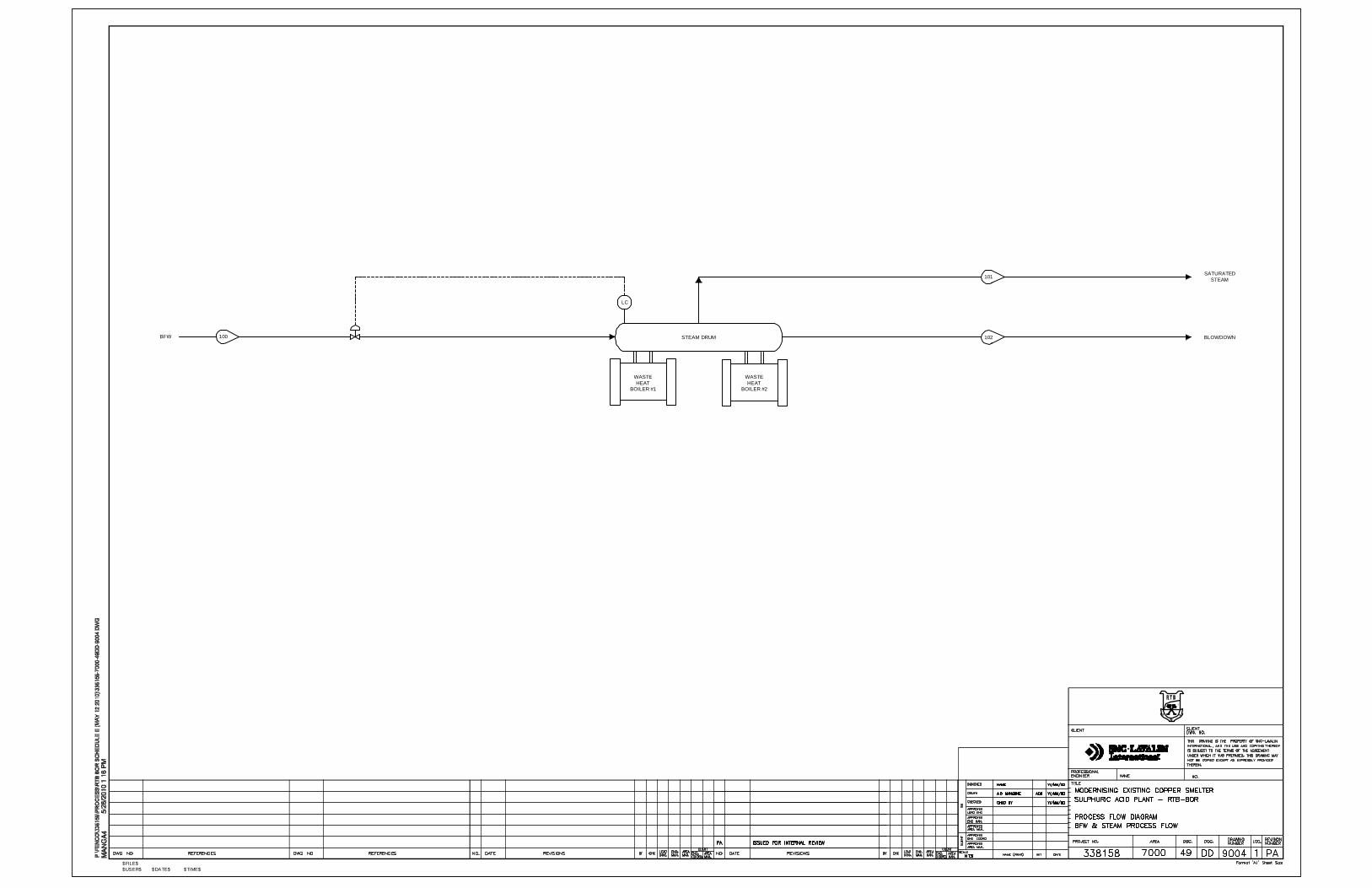
The off-gas from the FSF uptake shaft enters the WHB radiant section where it will be cooled to form steam by indirect heat exchange with boiler feed water flowing in the membrane tube wall.
The partially-cooled off-gas enters the convection section at a temperature of about 750oC where it will be further cooled along the length of this section by indirect heat exchange to form steam with boiler feed water flowing in pendant tube-banks suspended in the gas flow.
EIA Study – New Smelter and Sulphuric Acid Plant Project
University of Belgrade Faculty of Metallurgy
Section 5 Page 18
Flue dust suspended in the off-gas will consist of mechanically entrained dust; vaporised / condensed elements of the dry charge; and highly volatilised gaseous fumes of the dry charge impurity components. During cooling, the oxide flue dust will tend to form sulphates according to the following reaction-type which is highly exothermic:
MeO + SO2 + 1/2O2 = MeSO4
The dust mass will increase due to the above reaction. As the stickiness of poorly sulphated dust is high, sulphating will be performed in a controlled manner in the radiant section to optimize dust physical characteristics.
Part of the oxygen needed will be pre-mixed into the off-gas stream by injecting technical oxygen through nozzles into the FSF settler. The degree of sulphating of the entrained dust will be controlled by combustion air blown through nozzles at the inlet to the radiant section. Part of the sulphated dust will settle in the WHB dust hoppers and the remainder will be recovered downstream in an ESP.
The oxygen content of the process off-gas will be controlled to balance the required degree of sulphation of dust against the need to minimise SO3 gas formation.
Off-gas at about 350oC will exit the WHB and be ducted to a hot ESP for removal of the remaining entrained dust.
In the ESP, the dust particles will be electrically charged by the corona of discharge electrodes and migrate under the influence of a strong electric field to collection electrodes where they will be deposited. The discharge and collection electrodes will be rapped by hammers and the dust will move vertically down the collection electrodes until it drops off at the bottom into dust collection hoppers.
All the dust from the flash smelting process collected in the WHB and ESP will be re-circulated to the FSF.
The de-dusted off-gas containing typically 150 mg/Nm3 residual dust will be ducted to an induced draught fan. This fan will discharge the cleaned off-gas to the wet gas cleaning plant whilst maintaining the required FSF settler freeboard pressure at about -50 to -100Pa.
PSC Off-Gas System
Gas Collection Hood
Converter off-gas will be collected in closely fitting hoods mounted above each converter mouth. Air dilution of the off-gas by ambient air ingress of typically around 110% of the equivalent volume of process off-gas takes place and will pre-cool the primary off-gas.
EIA Study – New Smelter and Sulphuric Acid Plant Project
University of Belgrade Faculty of Metallurgy
Section 5 Page 19
The air gap is necessary to prevent to hood being welded to the vessel by splash. The ingress air will reduce the amount of water subsequently required for evaporative cooling. The dilution air enters via the side seals, back-flap and front of the hood.
Certain panels in the hood will be cooled by a dedicated closed circuit cooling water system common to both modernised converters. Heat energy will be removed from this closed circuit by indirect heat exchange with cooling tower water.
Evaporative Cooling Chamber (ECC)
The off-gas exits the converter hood at a temperature in the range 500–700oC and enters a horizontal ECC where it will be cooled by an evaporative spray cooling technique to about 350oC. The sonic-type spray equipment will have the capability to rapidly control the outlet temperature of the spray chamber over a wide range of gas enthalpies to cater for variations in converting conditions, blowing rates and hood dilution air ingress.
In order to ensure complete evaporation, thus ensuring a dry dust hopper during operation, it will be necessary to generate a water spray consisting of fine droplets, normally less than 200 microns in size. The purpose of the spray atomisation system will be to provide sufficient air quantity and pressure for efficient atomisation of water at the spray nozzles, thereby ensuring complete evaporation of water and rapid cooling of the converter off-gas. Dust fall-out in the chamber will be removed by a draglink conveyor, collected and returned to the smelting process.
Each converter will have its own dedicated gas collection hood and horizontal evaporative cooling chamber. The cooled off-gas from the outlet of the horizontal cooling chamber will be ducted to a common converter manifold via high velocity ducts into a wet gas scrubber. After wet scrubbing (described in the acid plant section), wet scrubbed converter gas will be mixed together with wet scrubbed FSF off-gas in a mixing chamber before ducting to the wet ESPs and sulphuric acid plant.
Equipment Description
FSF Off-Gas System
Waste Heat Boiler
The FSF waste heat boiler (WHB) is a forced-circulation type boiler that will consist of radiant and convection sections. The WHB will produce saturated steam at 6 MPa pressure. The heat exchange area will be maximised by the installation of tube screens in the radiant section and by banks of pendants in the convection section.
EIA Study – New Smelter and Sulphuric Acid Plant Project
University of Belgrade Faculty of Metallurgy
Section 5 Page 20
WHB main auxiliary equipment will consist of: steam drum; silencer; blow down tank; circulation water pumps; and mechanical dust rapping system with spring hammers.
There will be three circulation water pumps: two electric pumps and one steam turbine pump (standby) located close to the boiler. The electric pumps will be connected to the emergency power supply.
Dry Electrostatic Precipitator
The cooled off-gas from the FSF WHB will be drawn through a single four or five field dry ESP. The ESP will have inlet and outlet plenums and dust collection hoppers and be thermally insulated to prevent heat losses and minimise corrosion.
The gas flow will be evenly distributed by baffle plates in the ESP. The dust collection plates and discharge electrodes will be suspended vertically in the chamber and will be automatically and sequentially rapped by hammers located out of the gas stream.
The dust hoppers will be provided with air-lock valves to prevent ingress of air. Dust collected in the ESP will be transported via drag link conveyors and pneumatic handling systems that feed the recycle dust bin.
Transformer / rectifier sets will be mounted on the ESP roof.
Induced Draught Fan
The cooled and cleaned off-gas will be ducted to an induced draught fan rated at 47,800 Nm3/h that controls the draught in the FSF settler freeboard.
Secondary Gas Handling
The matte and slag launders, matte ladle and slag pot areas, and all tap hole openings will be fitted with gas hoods for the collection of fugitive emissions. The FSF area ventilation gases will be collected and ducted to a bag house and the cleaned gas discharged to atmosphere via a gas fan and stack.
Recycled Dust
The WHB and ESP dust hoppers will be fitted with drag link conveyors for transporting the flue dust. Large dust lumps from the WHB will be crushed in a roller crusher. The crushed dust will be conveyed together with ESP dust by drag link conveyors. A dense phase pneumatic conveying system will transfer the dust to the flue dust bin above the FSF reaction shaft.
All the dust produced from the flash smelting process will be re-circulated to the FSF via the dust loss-in-weight feeder.
EIA Study – New Smelter and Sulphuric Acid Plant Project
University of Belgrade Faculty of Metallurgy
Section 5 Page 21
During short stoppages of the dust conveying system, flue dusts from the WHB and ESP can be by-passed to the dust buckets from the dust hoppers of the drag-link conveyors. This dust will be re-circulated to the bedding plant.
PSC Off-Gas System
Gas Collection Hood
The PSC off-gas collection hoods will be panelled chambers mounted over the converter mouths that capture the primary off-gas. They will fit as closely as practicable to the converters to limit infiltration air, and will use labyrinth seals to further minimize in-leakage.
The material of each air-cooled hood panel will be cast steel. Water-cooled panels will be fabricated from steel plate. The panels will be bolted together with a compressible gasket material that will ensure air-tight joints between the panels.
There will be a common single water-cooling system for each of the two hoods. The water cooling tank, pumps and heat exchanger will be located at ground level.
A closed loop system will use demineralised water (chemically dosed to prevent corrosion) as the cooling medium. The heat will be removed in a plate heat exchanger array by indirect exchange with water supplied from an open circuit cooling tower.
Each hood will be provided with a sliding door at the front to enclose the mouth when the converter is blowing and to allow the addition of matte and solid materials or the pouring of slag and blister copper when open.
A moveable flap at the back of the hood will seal when the converter is in stack or, by partial opening, will allow limited control of hood air dilution. It will fully open to allow accretions from the hood uptake to drop out.
Provision will be made for the addition of flux and reverts through the side of the hood.
Evaporative Cooling Chamber (ECC)
The ECCs will be horizontal rectangular chambers connected to the exit of the converter hoods by an expansion joint. The chambers will be approximately 4m wide by 5m high.
The front portion (about one-third) of the chambers will be made of cast steel panels and the rear of the chamber from fabricated steel panels. The lower portions of the chambers will be single trough hoppers with a drag link conveyor. Dust collected in the ECC will be transported via a drag link cross-conveyor to a tote bin. This will be manually transported by forklift truck to the bedding plant.
EIA Study – New Smelter and Sulphuric Acid Plant Project
University of Belgrade Faculty of Metallurgy
Section 5 Page 22
The hood off-gas will be cooled by an evaporative spray cooling system that will include HP water pumps; air receiver; a valve rack and controls; piping and lances. Hoists will be provided to raise and lower the position of the lances in the chambers.
The gas outlet of each ECC will connect via high velocity ductwork to a common manifold that connects to the inlet of a wet gas scrubber. The high velocity ducts will each be fitted with a butterfly damper for converter hood draught control and a vertically acting isolation valve.
The gas outlet of each ECC will connect via high velocity ductwork to a common manifold that connects to the inlet of a wet gas scrubber. The high velocity duct of each converter will be fitted with a butterfly damper for converter hood draught control and a vertically acting isolation valve.
5.1.8 Acid Plant
The gas flow to the sulphuric acid plant will vary considerably. The flow of FSF off-gas will present a base-line (almost constant) primary gas flow to the acid plant for a nominal 7,920 hours per year. The converter operation is, however, a batch process with a single converter blowing or not at any one time. The in-stack time is estimated to be 42%, sending gas to the acid plant for 3,350 hours each year. Thus for a minimum of 4,570 hours per year, the gas feed to the acid plant will comprise FSF gas only. There will be occasions where only converter gas will be going to the acid plant, but these are upset conditions and should not amount to more than a few hundred hours per year.
The feed gas from the copper smelter contains dust, metallic fume, halides and sulphur trioxide. These materials must be removed from the gas before entering the drying section of the acid plant.
Process Description
The process described includes the following systems:
• Wet gas cleaning;
• Contact & absorption;
• Strong acid circulation;
• Preheater system;
• Steam generation;
• Acid sampling; and
EIA Study – New Smelter and Sulphuric Acid Plant Project
University of Belgrade Faculty of Metallurgy
Section 5 Page 23
• Cooling water.
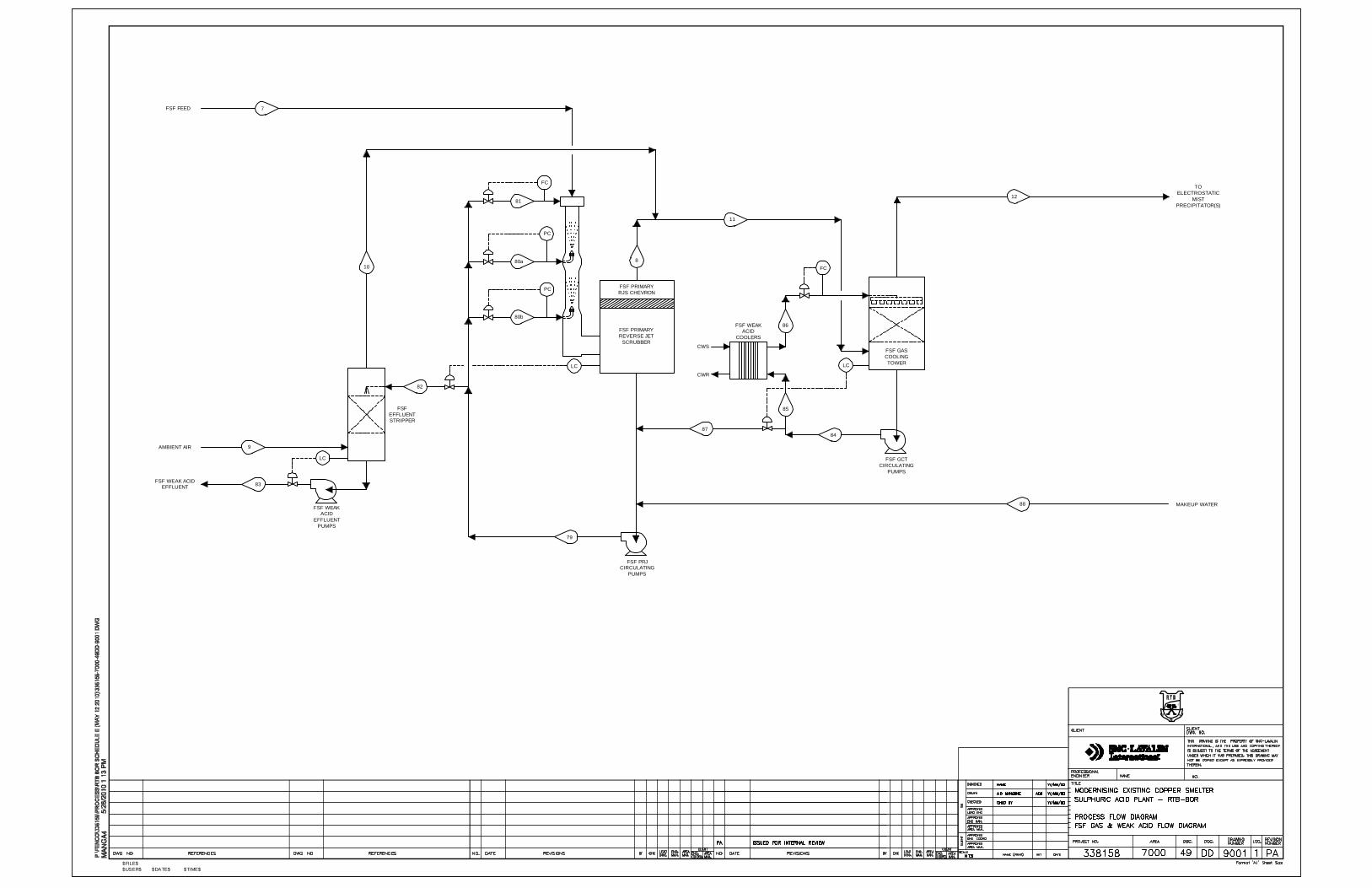
Wet Gas Cleaning System
FSF Wet Gas Cleaning
This wet gas scrubber can have many physical configurations, but all share the common purpose of bringing the gas into intimate contact with scrubber solution to simultaneously cool and clean the gas. Vaporization of water from the solution will bring the solution and the gas to or near to the adiabatic saturation temperature, which for the case of FSF gas that has passed a waste heat boiler and Hot ESP, will be around 55 to 60oC. The pressure drop in the gas phase across the scrubber is not highly dependent on the scrubber configuration for a given target gas cleaning efficiency, and will be in the order of 5 kPa of water gauge during “normal” flow conditions. Both Venturi based and DynaWave based technologies are described below.
Suspended particles in the gas phase, as well as some fume that condenses while the gas is cooling, will be captured in the liquid phase. In addition, any SO3 in the gas will also report to the solution, increasing the solution acidity.
The saturated gases will proceed to gas cooling. Gas cooling is required to lower the moisture content of the gas so that the acid plant water balance can be maintained. To make sulphuric acid, H2SO4, there can not be more molecules of H2O than SO2, so the volumetric concentration of water must be lower than that of SO2. As the SO2 content of the gas is high, no cooling is required to achieve the necessary ratio. Nonetheless, to give an adequate operating envelope of the acid plant, cooling to under 45oC is recommended. Cooling will be effected by passing the gas through a pack bed tower with cooled recirculating scrubber liquor. The liquor will be cooled in a plate heat exchanger with open circuit cooling tower water to remove the heat.
Solids accumulate in the scrubber liquor, which can be tolerated to varying levels depending on the scrubber technology selected. A blowdown will be required so as not to exceed the maximum permissible solid loading. The blowdown is usually equivalent to the quantity of water condensed from the gas phase in the cooling tower plus any fresh water that is used to flush the wet ESPs. However, for scrubbing technologies that can only tolerate low amount of solids, especially if applied to gases that have little moisture as is the case for FSF gas cooled in a waste heat boiler, make-up water may need to be added to control scrubber liquor solids percentage. There are also instances where the acidity of the liquor must be controlled by make-up water addition, or solubility of problematic minor elements such as selenium maintained by dilution. The blowdown typically referred to as weak acid bleed or weak acid effluent is sent to an effluent treatment plant for further treatment before discharge.
EIA Study – New Smelter and Sulphuric Acid Plant Project
University of Belgrade Faculty of Metallurgy
Section 5 Page 24
PSC Wet Gas Cleaning
Similar to the wet gas scrubber described above, this device can have many physical configurations. For the case where PSC gas will be collected in tight fitting hoods and sent directly to wet scrubbing, the adiabatic saturation temperature will be around 70oC. The pressure drop in the gas phase across the scrubber will be in the order of 6 to 7.5 kPa of water gauge during “normal” flow conditions to account for the increased cleaning duty required in the absence of a Hot ESP.
The saturated gases will be cooled to around 30 to 33oC so that a sufficiently low moisture content to respect the water balance on the rare occasions when the acid plant is treating only converter gas is achieved.
Weak acid bleed will be sent to an effluent treatment plant for further treatment before discharge.
Venturi Based Gas Cleaning System
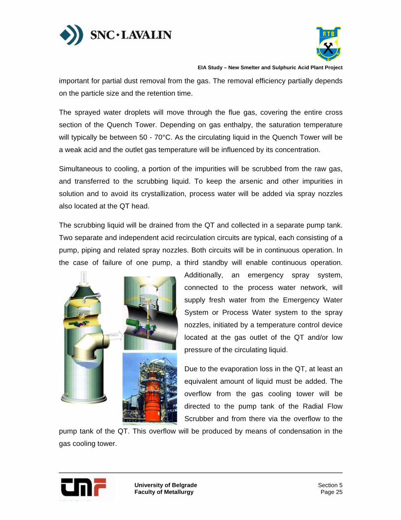
This technology will consist of a Quench Tower (QT), a Venturi Scrubber (RFS), a Gas Cooling Tower (GCT), an SO2 Stripper and three sets (2 in operation, and 1 stand-by) of Wet Electrostatic Precipitators (WESP) in parallel, with each set of WESP including a primary WESP and a secondary WESP.
The off-gas coming from the FSF Hot Gas ID Fan or from the PSC Manifold will enter via a hot gas duct to the gas cleaning system at the specially designed vertical gas inlet nozzle. The gas will enter the cross-current zone of the scrubber and passes through the hot/cold zone. This cooling will reduce thermal stress of the brick lining.
Circulating weak acid will be
injected co-currently through spray
nozzles made of corrosion and
erosion resistant alloy. The gas
will be quenched and saturated by
means of circulating liquid sprayed
from nozzles each independently supplied with scrubbing liquid located in the Quench
Tower head. Adiabatic cooling to saturation temperature will be achieved in this zone of
the scrubber. The high turbulence between the gas and the particles in this section are
EIA Study – New Smelter and Sulphuric Acid Plant Project
University of Belgrade Faculty of Metallurgy
Section 5 Page 25
important for partial dust removal from the gas. The removal efficiency partially depends
on the particle size and the retention time.
The sprayed water droplets will move through the flue gas, covering the entire cross
section of the Quench Tower. Depending on gas enthalpy, the saturation temperature
will typically be between 50 - 70°C. As the circulating liquid in the Quench Tower will be
a weak acid and the outlet gas temperature will be influenced by its concentration.
Simultaneous to cooling, a portion of the impurities will be scrubbed from the raw gas,
and transferred to the scrubbing liquid. To keep the arsenic and other impurities in
solution and to avoid its crystallization, process water will be added via spray nozzles
also located at the QT head.
The scrubbing liquid will be drained from the QT and collected in a separate pump tank.
Two separate and independent acid recirculation circuits are typical, each consisting of a
pump, piping and related spray nozzles. Both circuits will be in continuous operation. In
the case of failure of one pump, a third standby will enable continuous operation.
Additionally, an emergency spray system,
connected to the process water network, will
supply fresh water from the Emergency Water
System or Process Water system to the spray
nozzles, initiated by a temperature control device
located at the gas outlet of the QT and/or low
pressure of the circulating liquid.
Due to the evaporation loss in the QT, at least an
equivalent amount of liquid must be added. The
overflow from the gas cooling tower will be
directed to the pump tank of the Radial Flow
Scrubber and from there via the overflow to the
pump tank of the QT. This overflow will be produced by means of condensation in the
gas cooling tower.
EIA Study – New Smelter and Sulphuric Acid Plant Project
University of Belgrade Faculty of Metallurgy
Section 5 Page 26
Either to keep the concentration of impurities such as solids, arsenic, chlorine and
fluorine below a desired maximum level or to keep the total liquid level in the range of
the hydraulic design of the plant, a constant weak acid stream will be withdrawn, which
will be pumped to the effluent SO2 Stripping Tower.
The QT shell will be made from carbon steel protected from corrosive media with a soft
rubber lining. The complete QT shell will be lined with acid resistant bricks upon which a
layer of carbon bricks is applied for protection against hydrofluoric acid. The inlet elbow
of the QT will be covered by one layer of heat resistant bricks for thermal protection and
a layer of acid resistant bricks on the gas side. This design ensures strong protection
and thus a long lifetime of the rubber lining.
After the quench tower, the gases will pass through the Venturi flow scrubber. One
particular manufacturer offers an adjustable pressure drop scrubber developed for
conditions in off highly variable gas flowrate. For this device, the scrubbing zone is
formed by two rings between which the gas and the scrubbing liquid flow radially from
inside to the outside. The maximum relative velocity between gas and scrubbing liquid,
which is the main criteria for scrubbing, is located at the narrowest point between the two
rings. The cross section of the scrubbing zone may be modified by adjusting the lower
ring. This enables a constant differential pressure and consequently a uniform scrubbing
efficiency to be maintained even in the case of fluctuating gas volumes. The scrubbing
zone is controlled as a function of the differential pressure. By adjusting the scrubbing
zone, the gas flowrate can be changed by a ratio of up to 1:10 while maintaining a
constant pressure drop. This feature permits optimum adjustment to varying modes of
operation. It is especially suitable for batch processes in converters.
The collecting efficiency of the scrubber can be defined as required, irrespective of
fluctuating raw gas loads; and
Even for critical substances like As, Se or Pb, high collecting efficiencies are achieved.
Since radial flow scrubbers can be adjusted as required for the respective collecting
efficiency the scrubber can be operated at optimum differential pressure which
conserves energy.
EIA Study – New Smelter and Sulphuric Acid Plant Project
University of Belgrade Faculty of Metallurgy
Section 5 Page 27
Table 5.1.1 Pressure drop of Venturi Scrubber and Radial Flow Scrubber at varying gas flow rate
PSCs have two operating modes, full flowrate during blowing and no flowrate when on
stand-by. During blowing, the variation in flow between that experienced with clean
tuyeres as opposed to dirty tuyeres is a function of the diligence of the converter
operator, and is not typically large.
The difference in off-gas volume arriving at the scrubber between the slag blow and
copper blow is about 6%, also a small change. As a consequence, the amount of
movement made by the variable throat to achieve constant scrubber efficiency is small.
Similarly, the off-gas flowrate from a FSF is relatively constant so the throat adjustments
are very minor.
As a consequence, the minor advantage of tuning the throat to modulate the pressure
drop is normally outweighed by the cost of maintaining the system, so the throat is set at
a constant setting that provides satisfactory performance during regular operation. The
impurity loading in the gas also drops with flowrate, so the need to maintain scrubber
efficiency at lower flows is unnecessary. When there is no flow, the scrubber throat
setting is irrelevant.
For these reasons, variable throat control has only been briefly adopted. If the plant were
to be designed to mix the FSF and PSCV gases before a single scrubber, variable throat
EIA Study – New Smelter and Sulphuric Acid Plant Project
University of Belgrade Faculty of Metallurgy
Section 5 Page 28
would hold some benefit, but to date, furnace gas and converter gases have generally
been scrubbed separately due to the difficulty of maintaining close draft control at the
furnace with a system that has to handle the intermittent converter gas flow as well.
The off-gas which will be adiabatically cooled in the scrubber passes through the packed
cooling tower where it is cooled. The condensate accumulating in the cooling tower will
be conducted to the scrubber circuit in order to make up for evaporation losses. The gas
outlet of the cooling tower will not typically be equipped with a droplet separator because
the irrigation system will be based on a weir trough system so that large weak acid
droplets will be produced. These large droplets will not be carried to the top of the low
gas velocity Cooling Tower.
The packed cooling tower will be chemically resistant against H2SO4 and other
impurities found in the gas stream such as chlorine. The shell of the Cooling Tower will
be made of FRP with a chemical resistant barrier.
Acidic waste water from the gas cleaning system will be pumped from the QT circulating
system to an SO2 stripping tower. The packed stripping tower shell will be made of FRP
with a chemical resistant barrier.
For stripping, ambient air will pass through stripping tower in counter current to the liquid.
Due to the lower pressure in the gas duct upstream of the Cooling Tower, a fan will not
be needed. The air flow rate will be controlled by dampers located at the stripping tower
inlet air flanges. The dissolved SO2 in the acidic waste water will be reduced to 100 ppm
or less.
The stripped weak acid will be pumped to the effluent treatment plant by a horizontal
centrifugal pump (one in operation and one on stand by).
Six WESPs will be arranged in three trains, each consisting of two stages. Two WESP
trains will be in operation while one train serves as standby.
All parts in contact with the gas stream will be either homogeneously lead lined steel or
PP and FRP with chemical resistant liner / barrier.
EIA Study – New Smelter and Sulphuric Acid Plant Project
University of Belgrade Faculty of Metallurgy
Section 5 Page 29
DynaWave® Based Gas Cleaning System
The DynaWave® Scrubbing System will consist of a Reverse Jet scrubber followed by a
gas cooling tower.
The gas first will enter the primary scrubber where it will be quenched and scrubbed with
a counter-current spray of weak acid passing through large bore spray nozzles. Dust,
fume and mist particles will be scrubbed from the gas and at the same time, the gas will
be cooled by evaporation of water from the weak acid. The weak acid will be circulating
through the scrubber without cooling. From the primary scrubber, the gas will flow to a
packed cooling tower.
The inlet barrel of the primary scrubber will be protected against high temperature by the
presence of a weir bowl. The weir bowl will provide a uniform liquid film flowing down the
inside wall of the inlet barrel. This will prevent the inlet barrel from coming in contact with
the high inlet temperature gas. Liquid will be circulated back to the weir bowl via a
recirculation pump. Because the gas will be fully quenched after the first froth zone, all
downstream equipment can be made out of FRP.
Emergency spray nozzles will be included in the system to protect the FRP
disengagement vessel from excessively high temperatures resulting from failure of the
circulation pump. Low liquid flow to the Reverse Jet or high-high temperature in the
vessel will activate the emergency spray nozzles to quench the hot inlet gas.
In the packed cooling tower, the gas will pass through random plastic packing where it
will be cooled by counter-current contact with a circulating weak acid stream. The gas
will be sub-cooled and water will be condensed out of the gas stream. The condensation
also enhances mist and fume particle growth and subsequent downstream removal.
The condensed water will be cross-flowed from the Gas Cooling Tower to the Scrubber.
Weak acid will be removed from the scrubber based on the acid concentration and will
be sent to effluent stripping tower for removal and return of dissolved SO2 to the process
before discharge to the effluent treatment plant.
EIA Study – New Smelter and Sulphuric Acid Plant Project
University of Belgrade Faculty of Metallurgy
Section 5 Page 30
The amount of solids in the liquid will be limited to 10% or lower by the water balance of
the system.
The WESPs will be the final stage of gas cleaning to remove the remaining impurities
from the feed gas and will provide an “optically clear” gas to the Drying Tower.
The saturated gas enters the bottom of the first precipitator and passes up through the
precipitator tubes which have a high-voltage discharge electrode suspended down each
vertical axis. The mist droplets and particulate contained in the gas will receive a
negative electric charge from the discharge electrode and will be attached to the inside
wall of the collecting tubes, which will be earthed. The droplets agglomerate and drain to
the bottom of the precipitator and discharges via drain pipes will be assisted by a
periodic wash down spraying system. The gas from the first precipitator will exit the top
and enter the top of the second precipitator where it in turn will flow from top to bottom.
The cleaned gas then will exit the secondary precipitator.
Gas Conversion and Absorption
Process gas from the WESPs in the gas cleaning system will enter the bottom of the
drying tower and pass upwards through a layer of packing counter-current to a flow of
recirculated 96% H2SO4. The acid will remove water from the gas stream. After the gas
leaves the main packing, it will pass through a layer of spray eliminator packing and then
through a mesh pad which will remove entrained acid mist.
Dilution air will be added at the inlet to the drying tower, if necessary, to adjust the gas
strength to the contact section at the levels required for further processing.
The dried and essentially mist free gas leaving the drying tower will enter the suction
side of the SO2 blower. The blower will be of the single stage centrifugal type with a cast
iron casing, driven by an electric motor through a gear increaser.
Gases from the discharge of the blower will pass through the shell side of the cold and
hot gas-to-gas exchangers in series prior to entering the first pass of the converter. The
purpose of these exchangers will be to raise the temperature of the gases to the proper
EIA Study – New Smelter and Sulphuric Acid Plant Project
University of Belgrade Faculty of Metallurgy
Section 5 Page 31
operating temperature to effect conversion of SO2 to SO3 in the converter. Temperature
control on each exchanger will be by a series of bypass ducts and valves.
Since the reaction of SO2 and O2 to produce SO3 is exothermic, the gas temperature
must be reduced following each pass of the converter in order to permit further
conversion. Gases leaving the first pass of the converter will enter the tube side of the
hot gas-to-gas exchanger. The cooled gases leaving this unit will enter the second pass
of the converter.
The heat generated in the second pass of the converter will be removed by passing the
gas through the tube side of the hot interpass gas-to-gas exchanger prior to entering the
third pass of the converter. The temperature of the gases exiting the third pass will be
reduced by passing the gas through the tube side of the cold interpass gas-to-gas
exchanger and through the tubes of a waste heat boiler prior to entering the interpass
absorbing tower.
In the interpass absorbing tower, the SO3 component of the gas steam will be absorbed
in a recirculated flow of 98.5% H2SO4 as it passes up through the main packing in the
tower. After the gas leaves the main packing, it will pass through a layer of spray
eliminator packing and a Brownian movement candle type mist eliminator prior to exiting
the tower.
The gas from the interpass tower will then pass through the shell side of the cold
interpass gas-to-gas exchanger and the shell side of the hot interpass gas-to-gas
exchanger in series in order to achieve the strike temperature prior to entering the fourth
and final pass of the converter. In the fourth pass of the converter, the final conversion of
SO2 to SO3 will take place.
Once again, the hot gases from this pass must be cooled to a suitable temperature for
SO3 absorption in the final absorbing tower. To this end, the gases will pass through the
tube side of the cold gas-to-gas exchanger and through the tubes of a waste heat boiler
prior to entering the final absorbing tower.
EIA Study – New Smelter and Sulphuric Acid Plant Project
University of Belgrade Faculty of Metallurgy
Section 5 Page 32
In the final absorbing tower, the SO3 component of the gas steam will be absorbed in a
recirculated flow of 98.5% H2SO4 as it passes up through the main packing in the tower.
After the gas leaves the main packing, it will pass through a layer of spray eliminator
packing and a Brownian movement candle type mist eliminator prior to exiting the tower.
The gases are discharged to atmosphere via the process gas exit stack.
Preheater System
An external source of heat must be provided during initial plant start-up in order to obtain
proper operating temperatures in the converter and when low strength gas from the
smelter is below the autothermal point. This will be supplied by the preheater system
which will consist of a fuel fired furnace and gas-to-gas heat exchanger.
The furnace will operate on diesel fuel to produce products of combustion which pass
through the shell side of the preheater exchanger, counter-current to a flow of either
process gas or air on the tube side. Products of combustion from the exchanger will be
discharged to atmosphere via the preheater stack. Heated process gases or air from the
exchanger will be delivered to the converter.
Strong Acid Circulation
96% H2SO4 circulation acid for the drying tower circuit will be provided from a horizontal,
cylindrical, acid brick lined pump tank. One duty circulation pump, together with an
installed spare, will be supplied for this service. The duty pump will deliver acid to the
tower via the drying acid cooler. Acid from the drying tower will flow by gravity to the
pump tank. A side stream of 96% acid from the drying tower pump tank will be taken to
the absorbing tower circuit as required to control the level in the drying acid pump tank.
98.5% H2SO4 circulation acid for the two absorbing towers will be provided from the
interpass and final absorbing acid pump tank. This tank will be similar in design to the
drying acid pump tank. One duty and one installed spare pump will be provided for this
service. Acid from the tanks will be cooled in the absorbing acid cooler prior to entering
the two absorbing towers. Acid from the tower outlets will flow by gravity back to the
EIA Study – New Smelter and Sulphuric Acid Plant Project
University of Belgrade Faculty of Metallurgy
Section 5 Page 33
pump tank. Strength control in the absorbing acid circuit will be maintained by the
addition of fresh water to the pump tank.
A side stream of acid from the outlet of the absorbing acid cooler will be directed to the
drying acid pump tank on strength control from the drying acid loop.
Steam Generation System
Deaerated boiler feed water, from outside of the acid plant battery limits, will be provided
to the steam generation system, which includes a steam drum, an interpass absorption
tower low pressure boiler and a final absorption tower low pressure boiler, to generate 2
MPa steam for export from the acid plant. This steam will be suitable for use at the
steam dryer without being let down.
Acid Sample System
An acid sample system will be provided for each of the two acid loops (drying and final
absorbing) in the acid plant. These consist of three conductivity analysers, one for the
drying acid circuit and two for the absorbing acid circuit. A manual sampling station will
also be provided to allow samples of drying, absorbing and product acid to be tested.
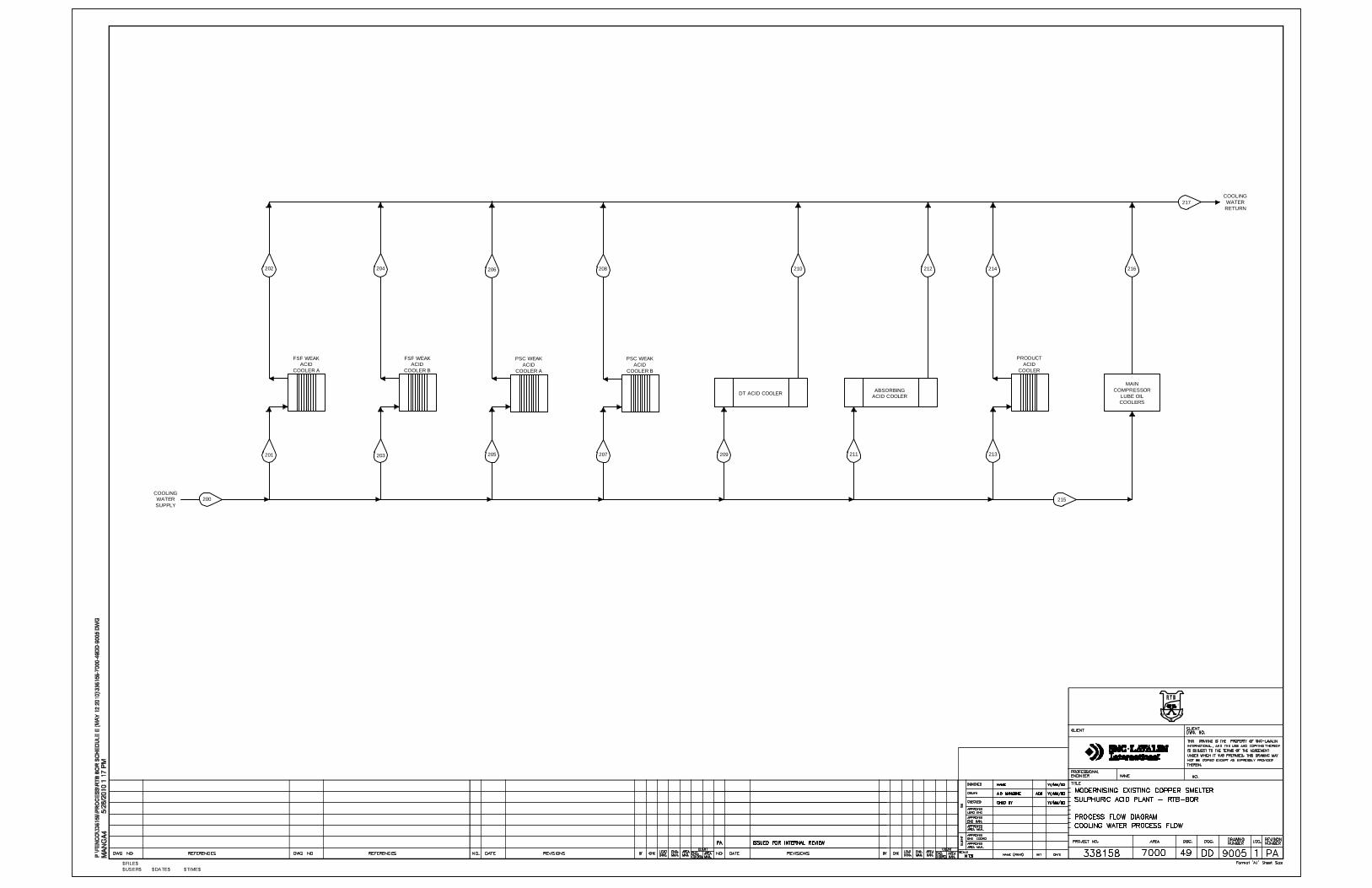
Water Cooling Tower
The Cooling Tower will be used for cooling treated water returning from the acid plant.
Water will be circulating in a ‘closed’ loop (open to atmosphere at the cooling tower), via
cooling water circulating pumps (i.e. open, recirculation mode).
The Cooling Tower will be modular, including 3-cell design, with partitions to allow
isolation and maintenance of any cell while the other cells remain in operation. Air will be
drawn through each cell by an induced draft fan at the top of the cell.
Overall heat rejection to the atmosphere will be accomplished using control of the air
mass passing through the tower, by varying the speed of one or more fans. Conductivity
elements will be provided in the return cooling water system to detect leaks.
Equipment Description
EIA Study – New Smelter and Sulphuric Acid Plant Project
University of Belgrade Faculty of Metallurgy
Section 5 Page 34
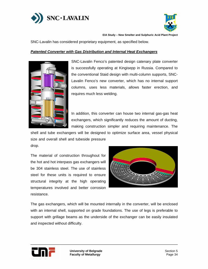
SNC-Lavalin has considered proprietary equipment, as specified below.
Patented Converter with Gas Distribution and Internal Heat Exchangers


![Sulphuric Acid Data[1]](https://static.documents.pub/doc/80x56/577d23741a28ab4e1e99d41e/sulphuric-acid-data1.jpg)


