129


GE Logiq E9/Vivid E9 Training Manual
© 2016 Conquest Imaging i
Table of Contents
Table of Contents ................................................................................... i
Module 1 Introduction .......................................................................... 1 Other Course Offerings ........................................................................1
Vivid E9 .......................................................................................................... 2
Module 2 System Hardware and Theory .............................................. 3 Vivid E9 Basic Block Diagram ......................................................................... 4
Electronic Sub-systems .........................................................................4 System Front End Components .............................................................5
E9 Front End Processor (FEP) ..................................................................5 Front End Signal Flow ..............................................................................6
Front End Signal Flow MRX Configuration .................................................... 7 System Backend Components...............................................................7
Back End Processor (BEP) ........................................................................7 Generic BEP Block Diagram ........................................................................... 8 Logiq E9 BEP .................................................................................................. 8
IO Board ..................................................................................................9 VIVID E9 Video Audio & USB Connectors ...................................................... 9
Patient I/O Module .............................................................................. 10 Touch Screen ........................................................................................ 10 Control Panel ........................................................................................ 11
Logiq E9 Control Panel ................................................................................ 11 Vivid E9 Control Panel ................................................................................. 12
Video Monitor ...................................................................................... 12 System Audio ....................................................................................... 13
Power Distribution Components......................................................... 13 Main Power Supply (MPS) .................................................................... 13
Vivid E9 Power Supply ................................................................................. 13 Temperature Control ........................................................................... 14 Power Down Sequences ....................................................................... 14
Normal Power Shut Down Sequence .......................................................... 14 Vivid E9 Shut Down ..................................................................................... 14 Logiq E9 Shut Down .................................................................................... 15 Forced Power Shut Down ............................................................................ 15 Unexpected Power Loss .............................................................................. 15
Module 3 Operating Modes ................................................................ 16 B-Mode ............................................................................................. 16 Harmonic Imaging .............................................................................. 16 M-Mode ............................................................................................ 17 Color Flow Doppler Mode .................................................................. 17 Power Doppler ................................................................................... 18 Pulsed (PW) Doppler .......................................................................... 18 Continuous Wave (CW) Doppler ......................................................... 18

GE Logiq E9/Vivid E9 Training Manual
© 2016 Conquest Imaging ii
Other Modes ..................................................................................... 19
Module 4 Network Configuration ....................................................... 20 DICOM ............................................................................................... 20 Prepare for Network Configuration .................................................... 20 GE Dataflows ..................................................................................... 20 Vivid E9 Connectivity ......................................................................... 21
Vivid E9 Dataflow Descriptions ............................................................ 21 Vivid E9 Dataflow Adjustments ............................................................ 22
Adjusting the Assigned Devices .................................................................. 23 Additional Outputs ............................................................................... 25 P1 / P2 / Record button configuration ................................................. 25 Unlock Patient Record .......................................................................... 26
Logiq E9 Connectivity ......................................................................... 26 TCPIP .................................................................................................... 27 Device ................................................................................................... 28 Service .................................................................................................. 28 Basic DICOM Preset Parameter Descriptions ....................................... 29 DICOM Image Storage .......................................................................... 29 DICOM Performed Procedure .............................................................. 30 DICOM Print ......................................................................................... 30 DICOM Query/Retrieve ........................................................................ 32 DICOM Storage Commitment .............................................................. 33 DICOM Worklist.................................................................................... 33 Standard Print ...................................................................................... 35 Video Capture ...................................................................................... 35 Save As ................................................................................................. 35 Dataflow ............................................................................................... 36 Print Button Setup ................................................................................ 36 Removable Media ................................................................................ 37
Formatting Removable Media .................................................................... 38 Miscellaneous ...................................................................................... 38
Module 5 Preventive Maintenance .................................................... 43 System Backup ................................................................................... 43
Backup Procedure for Vivid E9 ............................................................. 43 Restore Procedure for Vivid E9 ............................................................ 46 Backup Procedure for Logiq E9 ............................................................ 48 Backup and Restore Strategy: Patient Data ......................................... 50
Cleaning the Air Filters ....................................................................... 51 Cleaning the Trackball Vivid E9 (OP-5) ................................................ 51
Module 6 General Safety Precautions ................................................ 53 Electrical Safety .................................................................................... 53 Electromagnetic Interference .............................................................. 54 Electrostatic Discharge ESD Precautions .............................................. 54 Fire Safety............................................................................................. 55

GE Logiq E9/Vivid E9 Training Manual
© 2016 Conquest Imaging iii
General Cautions .................................................................................. 55
Module 7 Troubleshooting ................................................................. 56 Normal Power On/Boot Sequence ...................................................... 56
Connect AC (mains) Power to the Vivid E9/Logiq E9 ........................... 56 Turn System ON ................................................................................... 57 Sleep Mode .......................................................................................... 57
Troubleshooting Log/Image Capture................................................... 58 Trouble Shooting Network Issues ....................................................... 59 Trouble Shooting Operator Panel Issues ............................................. 61
No Audio .............................................................................................. 61 No Video on LCD Display ...................................................................... 62 Wrong Key Activated on the Touch Panel ........................................... 62 Touch Panel Not Responding ............................................................... 62 Probe Recognition ................................................................................ 62
Module 8 Parts Replacement ............................................................. 64 System Power Down .......................................................................... 64 Chassis Cover Removal ....................................................................... 64
Side Covers ........................................................................................... 65 Top Cover ............................................................................................. 65 Foot Rest Bumper ................................................................................ 65 Front Cover........................................................................................... 66 Back Filter Cover .................................................................................. 66 Rear Cover ............................................................................................ 67 Remove Bulkhead Cover ...................................................................... 68
Slots for Bulkhead Cover ............................................................................. 68 Remove Handle, Left/Right Top Handle .............................................. 69
Release Hatches .......................................................................................... 69 Handle Left Top / Handle Right Top reinstallation............................... 69 Palm Rest Assembly ............................................................................. 70
LCD Monitor Replacement ................................................................. 71 Logiq E9 LCD Monitor Replacement .................................................... 71
LCD Monitor (P/N 5167953) Replacement.................................................. 71 LCD Monitor V2 (5392293-21) Replacement .............................................. 72
Vivid E9 LCD Monitor Replacement ..................................................... 72 Replacing the LCD Arm assembly ........................................................ 73
Cables at Bulkhead ...................................................................................... 74 Install the LCD Arm Assembly .............................................................. 75
LCD Mount Lock Handle .............................................................................. 75 Replacing the LCD Cables ................................................................... 75
Third Arm Cover Removal ........................................................................... 76 Second Arm Section Cover Removal ........................................................... 76
Install the LCD Cables ........................................................................... 77 Feed Cable Through First Arm ..................................................................... 77 First (left) Arm Section Midpoint Location .................................................. 78 Second Arm Section Midpoint Location ...................................................... 78 Feed Cable through Third Arm .................................................................... 78

GE Logiq E9/Vivid E9 Training Manual
© 2016 Conquest Imaging iv
Clip Location Securing Power and Video Cables to Bracket ....................... 79 LCD Mount Lock Replacement Procedure ........................................... 79
Replacing Upper Operator Panel/Touch Panel Assembly ..................... 80 Re-Install Upper OP Panel/Touch Panel Assembly .............................. 81
OP Grounding ............................................................................................. 81 Replace Lower Operator Panel ........................................................... 83
View from Below with Drawer Extended ................................................... 83 Replacing the Vivid E9 Trackball ......................................................... 84
Re-Install the Trackball ......................................................................... 84 Remove the Lower Operator Panel Frame .......................................... 85 Lower Frame Assembly Installation ..................................................... 86
Remove Bulkhead Board .................................................................... 87 Bulkhead Board Screws .............................................................................. 87
Re-Install the Bulkhead Board .............................................................. 87 Remove the Bulkhead Plate ................................................................. 87 Re-install the Bulkhead Plate ............................................................... 88
XYZ Buttons and Button Board Replacement ...................................... 89 Top Console Adjustment Controls .............................................................. 89 XYZ Buttons ................................................................................................ 89
Buttons Removal Procedure ................................................................ 90 Button IF Board Replacement .............................................................. 90
XYZ Mechanism Frog Legs .................................................................. 91 XY Mechanism Installation Procedure ................................................. 92 XY Park Lock Replacement ................................................................... 93 XY Park Lock Removal .......................................................................... 93 Z-Mechanism replacement .................................................................. 94
Z-Mechanism .............................................................................................. 94 XYZ Control Assembly Replacement .................................................... 95
Main Power Suppy Replacement ........................................................ 96 Vivid E9 Main Power Supply Replacement .......................................... 96 Logiq E9 Main Power Supply Replacement .......................................... 97
Back End Processor (BEP) ................................................................... 98 Logiq E9 BEP Replacement ................................................................... 99 Vivid E9 BEP Replacement ................................................................. 102
Front End Parts Replacement ........................................................... 104 Vivid E9 Front End Processor (FEP) .................................................... 104
Module 9 System Adjustments ......................................................... 107 Touch Screen Calibration .................................................................. 107 DC Offset Calibration ....................................................................... 108
When to do a DC Offset Calibration ................................................... 108 DC Calibration Procedure ................................................................... 108
Operator Panel Adjustments ............................................................ 109 Using the Park Lock Properly ............................................................. 109 Normal Operator Panel XY Movement .............................................. 110 XY Brake Adjustment .......................................................................... 111 Release the Park Lock Manually ......................................................... 111
GE Logiq E9/Vivid E9 Training Manual
© 2016 Conquest Imaging v
Glossary ............................................................................................. 112
Acronyms .......................................................................................... 115
Appendix 1 Network Configuration Worksheets .............................. 118 Checklist for Configuring Ultrasound System Network Parameters .. 118 Print Device Information .................................................................... 119 HIS/RIS Server Information ................................................................ 120 DICOM Devices to Connect to System: .............................................. 121 Other Needed Information: ............................................................... 121


GE Logiq E9/Vivid E9 Training Manual
© 2016 Conquest Imaging 1
Module 1 Introduction
This manual is specific to the GE Logiq E9/Vivid E9 systems field service training presented by the Conquest Imaging training department. After completing the training, you will:
Understand overall system operation.
Identify the parts, boards and modules.
Understand the role of each component in the system.
Be able to perform standard maintenance procedures.
Have the knowledge to troubleshoot common problems.
Be able to safely access and replace boards and modules.
Understand of some of the differences in configuration for different system versions.
Other Course Offerings
This course is one of many ultrasound training courses offered by Conquest Imaging.
The following are some of our current course offerings:
Basic Ultrasound
DICOM Standards and Networks Preventive Maintenance

GE Logiq E9/Vivid E9 Training Manual
© 2016 Conquest Imaging 2
Probe Care and Handling NFPA 99 Electrical Safety Crash Course OEM Platforms
To see the full descriptions and the scheduling of these courses, please visit our training department website:
http://conquestimaging.com/education/
You can use this margin for taking notes.
Vivid E9

GE Logiq E9/Vivid E9 Training Manual
© 2016 Conquest Imaging 3
Module 2 System Hardware and Theory
The goal of the System Hardware and Theory Module is to provide you with a solid grounding on the purpose of the GE Logiq E9/Vivid E9 system’s different components and how they function together within the system.
The Logiq E9 is a general system with the capability of performing cardiovascular, abdominal, urologic, pediatric and women’s health exams.and has been produced since 2009. The focus of the Vivid E9 is cardiovascular exams. We will use a color coded system to call out the differences where necessary. Text that appears in orange applies only to the Logiq E9 and green text applies only to the Vivid E9.
The GE Logiq E9 and the Vivid E9 systems are quite similar but there are some differences. There are also some differences between versions of the same system. For example, in later versions of the Logiq systems the functionality of the Digital Receiver Boards (DRXs), Analog Receiver Boards (GRXs) and the Global Front End Interface (GFI) are replaced with the single MRX board.
The three major functional blocks in all ultrasound systems are:
Front End – Includes transducer analog signal processing functions.
Back End – Includes user interface and system communication with DICOM systems.
Power Systems – Generates, regulates and supplies the required voltages to the various parts of the system.
In the GE E9 systems the GTX board(s) in the Front End Processor, generate the signals transmitted by the probes as ultrasound into the body. The Transmit bursts are routed from the GTX board via the XD bus to the Relay board where the ultrasound probes are connected.the input signals travel from the probe connector panel to the front end Front End Processor (FEP), then to the Back End Processor (BEP), and finally, the results are displayed on the monitor. System configurations are stored on a hard drive which resides inside the BEP, and all necessary software is loaded from the hard drive on power up.

GE Logiq E9/Vivid E9 Training Manual
© 2016 Conquest Imaging 4
Electronic Sub-systems
There are three main electronic sub-systems:
The Logiq E9 and Vivid E9 internal electronics are divided into the power supply and the two separate card cages refered to as:
Front End Processor (FEP) Back End Processor (BEP)
There are also three separate assemblies:
XYZ Controller Assembly Z-Axis Motor Assembly Operator Console Assembly, with:
LCD Monitor Upper Operator Panel Assembly (UOP) Lower Operator Panel Assembly (LOP) Bulkhead Optional Gel Warmer Optional TV Probe Holder
Vivid E9 Basic Block Diagram

GE Logiq E9/Vivid E9 Training Manual
© 2016 Conquest Imaging 5
System Front End Components
This section covers system frontend topics for the GE Logiq E9/Vivid E9. Front end is a general term for the parts of the ultrasound system that receive the reflections from acoustic energy that have been transmitted into the body and perform the various signal processing functions on them needed to produce an ultrasound image. The following are some of the components and functions that are found in a typical ultrasound system front end:
Transducers – Transmit focused acoustic energy and receive the resultant reflections.
High voltage switches – Used for multiplexing (connects a particular transducer element to a particular transmitter/receiver pair)
High voltage transmitters – Transmit analog data from the transducers.
Time Gain Control Amp (TGC) – A variable gain amplifier (VGA) is used to compensate for image variations due to tissue depth.
Analog to Digital converter and noise filtering.
Digital Beamformers – Upconverts signals which increases sample rates. The signals are stored in memory, apodized and summed.
Beamformed Digital Signal Processing – The digital beamformed signals received are processed into visual and audio outputs the process of which depends on if the transducer is B-mode (2D), Doppler, PWD or CWD.
The front end manages the input from the transducers, performs Analog to Digital conversion, Digital to Analog conversion along with many other signal processing functions.
E9 Front End Processor (FEP)
In the GE E9 systems the card cage that contains the front end electronics is referred to as the FEP. Different versions of the systems have different board configurations. See the “GE Logiq E9 / Vivid E9

GE Logiq E9/Vivid E9 Training Manual
© 2016 Conquest Imaging 6
Platform Hardware Revisions” Section in the presentation that accompanies this manual for details on specific configurations.
XD_BUS: TOP Plane (Two boards used). GRLY: Global (GECKO) Relay Board. GRX64 w/ CW: Global Receiver Board 64 channel. GRX128 / GRX128 w/ CW: Global Receiver Board 128 channel. GTX: Global Transmitter Board. DRX: Digital Receiver Board. GFI: Global Radio Frequency Interface Board. MRX: Multi Receiver Board (BT 2011 Logiq E9 only). PDP: Power Distribution Panel Board (BT 2011 Logiq E9 only). The MRX Board combines the functionality of the Digital Receiver Boards (DRXs), Analog Receiver Boards (GRXs) and the Global Front End Interface (GFI) Power Distribution PD The function of power distribution was previously supplied from DRX Boards.The Power Distribution Board replaces all power supplies previously present in DRX and GRX Boards, plus the monitoring circuitry for the card rack fan control.
Front End Signal Flow
The GTX boards generate the signals that are transmitted to the probes to generate ultrasound energy into the body. The transmit pulses are routed from the GTX board via the XD bus to the relay board (GRLY) where the ultrasound probes are connected.
The reflected ultrasound from the body structures are detected by the probes and converted into tiny electrical pulses. Those pulses are routed via the Relay board to the XD bus and sent to the RX boards. The GRX/MRX boards amplify the received signals. These signals are then routed to the DRX/MRX boards where the signals undergo signal processing such as A/D conversion. The processed signals are then transferred via the PCIe bus to the Back End Processor(BEP).
The BEP receives input commands from the Operator Panel (OP) and handles the communications with the rest of the system. The BEP delivers digital video signals to the LCD monitor, Touch Screen, optional internal Digital Video Recorder, and an optional internal printer. The Back End Processor also handles all communications to

GE Logiq E9/Vivid E9 Training Manual
© 2016 Conquest Imaging 7
and from the network (Ethernet).
System Backend Components
This section describes the System Back End topics for the GE Logiq E9/Vivid E9. The back end includes system blocks/components on the user interface side that perform functions such as master controller, signal processing, image memory, video layout, peripherals and user interface.
Back End Processor (BEP)
The Back End Processor (BEP) unit receives the data from the FEP electronics, stores it in memory, performs scan conversion to the pixel domain, and drives the system’s monitors.
Contains the HDD that holds the Base Image (Windows XP Embedded) and Application Software (System Specific). The BEP software also processes the Color Flow, Doppler, M-Mode data and the 3D/4D data.
The BEP is physically located in the left side of the system.
The main component of the BEP is the uBTX motherboard along with these major components:
Front End Signal Flow MRX Configuration
The BEP is system specific i.e. LE9 BEP vs. VE9 BEP are not interchangeable nor compatible with each other.

GE Logiq E9/Vivid E9 Training Manual
© 2016 Conquest Imaging 8
BEP Power Supply I/O Board HDD -- 160GB Hard Drive ADD Video Card for DVI DVR Card (Optional) Front Panel LEDs, etc. Battery Pack Graphics Adaptor
The BEP interconnects with the following parts of the system:
FEP card rack for signal processing, controls, and loading scan parameters.
Top console for Operator Panel (UOP and LOP) and LCD for video out.
Main Power Supply unit, to configure, communicate and control MPS outputs.
Controls the rest of the system based on user input from Operator Panel.
The following BEP models have been used for Vivid E9:
BEP6 was introduced in manufacturing in October 2012. The BEP6 is also called BEPY3.
BEP5 was introduced at the introduction of VIVID E9 and was phased out of manufacturing in October-November 2012. The BEP5 is also referred to as BEPY1 or BEPY2, depending on the installed System Software version.
Generic BEP Block Diagram
Logiq E9 BEP

GE Logiq E9/Vivid E9 Training Manual
© 2016 Conquest Imaging 9
Different I/O Boards are used for BEP6 and BEP5:
The BEP6 I/O Board has two connectors for connection to the BEP6 Motherboard.
The BEP5 I/O Board has one connector for connection to the BEP5 Motherboard.
IO Board
The IO Board interfaces between the BEP and:
The connectors on the rear side of Vivid E9 (video/audio/USB)
The top console
The internal printer
Audio for the speakers, the rear plugs and the DVR
VIVID E9 Video Audio & USB Connectors

GE Logiq E9/Vivid E9 Training Manual
© 2016 Conquest Imaging 10
Patient I/O Module
The Patient I/O module allows ECG inputs to be used in conjunction with patient studies. The scanned image that is displayed is synchronized with the ECG and PCG traces. In Doppler or M-Mode, the traces are synchronized to that particular mode’s sweep. The AUX input is capable of handling external ECG signals from other diagnostic ECG devices.
Touch Screen
The control panel touch screen enables access to different modes. The mode/function controls are organized in tabbed folders with potentially several pages within each folder.
The five buttons at bottom of the touch panel are both rotary and push buttons. The functionality of these buttons changes, based on the current mode/function.
Inputs for the patient I/O are not meant for patient monitoring they are meant for correlation with patient scans only.

GE Logiq E9/Vivid E9 Training Manual
© 2016 Conquest Imaging 11
Control Panel
The control panel is the main user interface, receives user inputs, communicates with the system host CPU via Universal Serial Bus (USB) ports and displays various outputs via the touch panel.
It includes the On/Off switch, controls used to manipulate picture quality, and controls used in Measure & Analyze (M&A), an alphanumeric keyboard and frogleg controls.
1.) Probe and Cord Holder 2.) USB Ports (2) 3.) Measurement Selection Menu and Joystick controls 4.) Keyboard 5.) Feature Keys: Elastography, Volume, Navigation, Loop View, Contrast 6.) Modes (B, M, CF, PDI, PW, CW, TVi) /Gain/XYZ Controls for 3D/4D Mode 7.) TGC 8.) Trackball, Trackball Keys, Pointer, Measure, Comment, Body Pattern, Clear, Zoom, 3D/4D, P1 9.) L/R, Start/Stop, Freeze 10.) Steer/Width/Depth/Reverse 11.) Auto 12.) P2, P3, P4 13.) Frogleg Controls (XYZ Mechanism)
Logiq E9 Control Panel

GE Logiq E9/Vivid E9 Training Manual
© 2016 Conquest Imaging 12
The keyboard is pulled out from beneath the control panel. 1. On/Off button 2. Patient selection, Probe selection, Protocol based acquisition, Worksheet and Image review 3. Active mode gain 4. 2D Gain 5. Scan mode selection 6. Zoom 7. Depth 8. Display controls, Annotation 9. Print, secondary capture 10. Freeze, 2D Freeze 11. Measurement, image store 12. Auto, cursor and angle 13. Trackball 14. TGC sliders 15. Loudspeaker volume control 16. Touch panel with adjustment rotaries 17. USB ports
Video Monitor
The system video monitor displays the ultrasound images. The Vivid E9 systems can have either a 17” or 19” LCD display. Different arms are used to support them. Logiq E9 systems have two different 19”versions of the LCD display.
Vivid E9 Control Panel
GE Logiq E9/Vivid E9 Training Manual
© 2016 Conquest Imaging 13
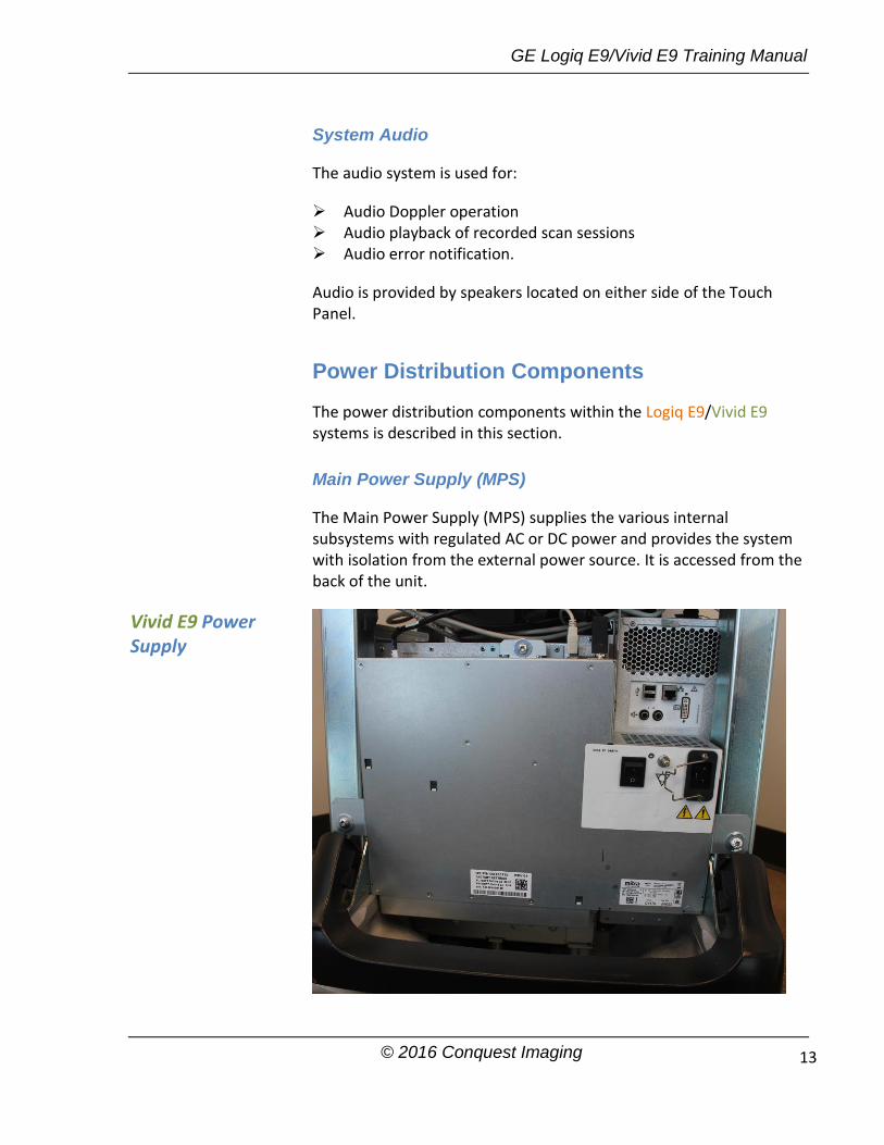
System Audio
The audio system is used for:
Audio Doppler operation Audio playback of recorded scan sessions Audio error notification.
Audio is provided by speakers located on either side of the Touch Panel.
Power Distribution Components
The power distribution components within the Logiq E9/Vivid E9 systems is described in this section.
Main Power Supply (MPS)
The Main Power Supply (MPS) supplies the various internal subsystems with regulated AC or DC power and provides the system with isolation from the external power source. It is accessed from the back of the unit.
Vivid E9 Power Supply

GE Logiq E9/Vivid E9 Training Manual
© 2016 Conquest Imaging 14
Power from the wall outlet (100 to 240 VAC, 50/60 Hz) is connected to the Main Power Supply. The MPS delivers the needed voltages to the rest of the Logiq E9/Vivid E9:
Internal Peripherals (110-115 VAC) Front End Rack (DC power with several voltages) Front End Rack (TXPSV1 and TXPSV2 for the transmitters) (TSV1
and TSV2 for the transmitters) Front End Rack (PMXVOUT for the probe channel multiplexers) Back End Processor (48 VDC) Operator Panel, LCD, XYZ motors (48 VDC) When the system is switched on an inrush current limiter reduces the peak input current. The power supply also contains an EMI filter to reduce EMI to acceptable levels. The power supply contains 15 Amp fast acting ceramic fuses (only to be replaced by the manufacturer).
Temperature Control
The MPS is equipped with an internal variable speed fan to provide temperature control. The temperature of the air entering the power supply and leaving the power supply are monitored. The fan speed is adjusted according to temperature monitored by sensors.
Power Down Sequences
There are three possible scenarios for power shut down of the unit:
Normal Power Shut Down Forced Power Shut Down Unexpected Power Loss
Normal Power Shut Down Sequence
Press the ON/OFF button (for a short time)
1. BEP detects the contact of Power (ON/OFF) switch. 2. PSON_N goes high. This triggers the Main Power Supply to shut down the output voltages. 3. Controller ACFAIL_N output signal goes low. 4. Controller TS_OK output signal goes low. 5. Controller turns OFF the TS (Transmit) voltages. 6. Controller turns OFF the PMX (Probe MUX) voltages. 7. Controller turns OFF voltages +/-15, +/-6, +11V, +24V.
Vivid E9 Shut Down
GE Logiq E9/Vivid E9 Training Manual
© 2016 Conquest Imaging 15
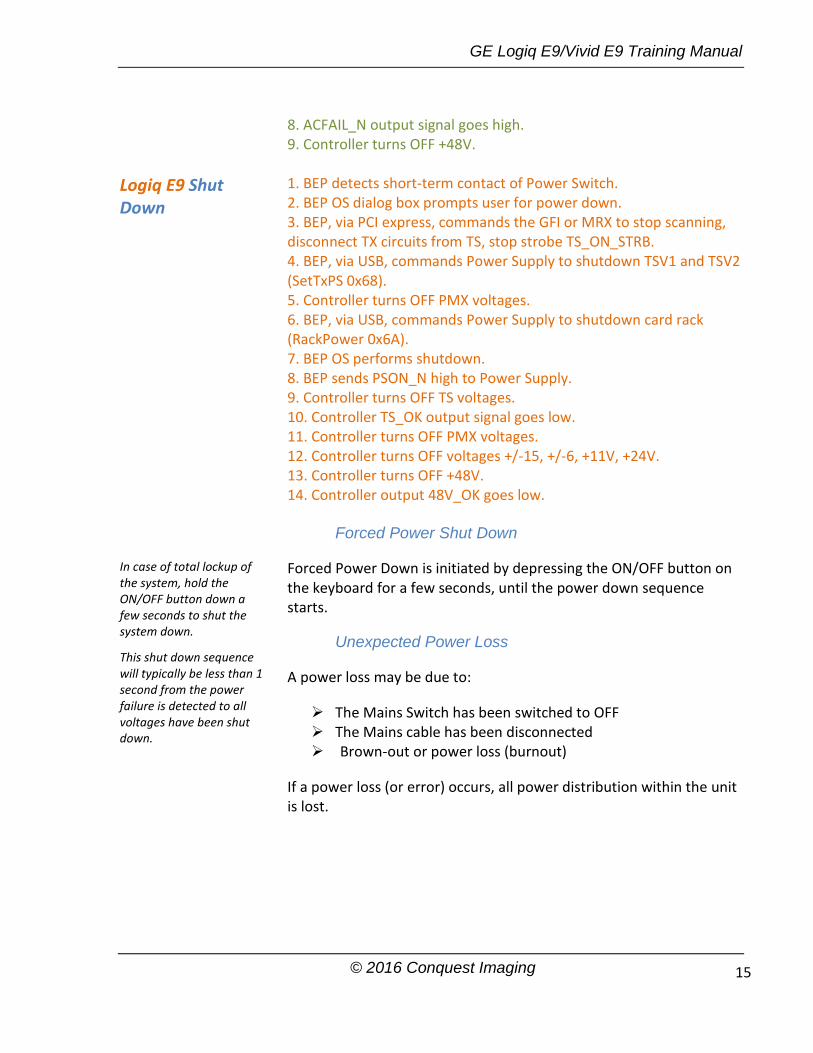
8. ACFAIL_N output signal goes high. 9. Controller turns OFF +48V. 1. BEP detects short-term contact of Power Switch. 2. BEP OS dialog box prompts user for power down. 3. BEP, via PCI express, commands the GFI or MRX to stop scanning, disconnect TX circuits from TS, stop strobe TS_ON_STRB. 4. BEP, via USB, commands Power Supply to shutdown TSV1 and TSV2 (SetTxPS 0x68). 5. Controller turns OFF PMX voltages. 6. BEP, via USB, commands Power Supply to shutdown card rack (RackPower 0x6A). 7. BEP OS performs shutdown. 8. BEP sends PSON_N high to Power Supply. 9. Controller turns OFF TS voltages. 10. Controller TS_OK output signal goes low. 11. Controller turns OFF PMX voltages. 12. Controller turns OFF voltages +/-15, +/-6, +11V, +24V. 13. Controller turns OFF +48V. 14. Controller output 48V_OK goes low.
Forced Power Shut Down
Forced Power Down is initiated by depressing the ON/OFF button on the keyboard for a few seconds, until the power down sequence starts.
Unexpected Power Loss
A power loss may be due to:
The Mains Switch has been switched to OFF The Mains cable has been disconnected Brown-out or power loss (burnout)
If a power loss (or error) occurs, all power distribution within the unit is lost.
Logiq E9 Shut Down
In case of total lockup of the system, hold the ON/OFF button down a few seconds to shut the system down. This shut down sequence will typically be less than 1 second from the power failure is detected to all voltages have been shut down.

GE Logiq E9/Vivid E9 Training Manual
© 2016 Conquest Imaging 16
Module 3 Operating Modes
The following general operating modes are available on E9 systems:
B-Mode
B-Mode is a two-dimensional image of the amplitude of the echo signal. It is used for location and measurement of anatomical structures and for spatial orientation during operation of other modes. In B mode, a two-dimensional cross-section of a three-dimensional soft tissue structure such as the heart is displayed in real time.
Ultrasound echoes of different intensities are mapped to different gray scale or color values in the display. The outline of the 2D (B-Mode) (B-Mode) cross-section is a sector, depending on the particular transducer used. B-mode can be used in combination with any other mode.
Harmonic Imaging
Tissue Harmonic Imaging, acoustic aberrations due to tissue, are minimized by receiving and processing the second harmonic signal that is generated within the insonified tissue. Coded Harmonics enhances near field resolution for improved small parts imaging as well as far field penetration. It diminishes low frequency amplitude noise and improves imaging technically difficult patients.
It may be especially beneficial when imaging isoechoic lesions in shallow-depth anatomy in the breast, liver and hard-to-visualize fetal anatomy. Coded Harmonics may improve the B-Mode (2D (B-Mode)) image quality without introducing a contrast agent.

GE Logiq E9/Vivid E9 Training Manual
© 2016 Conquest Imaging 17
M-Mode
In M-mode, soft tissue structure is shown as a scrolling display, with depth on the Y-axis and time on the X-axis. It is mostly used for cardiac measurements. M-mode is also known as T-M mode or Time-Motion mode. Ultrasound echoes of different intensities are mapped to different gray scale values in the display. M-mode displays time motion information derived from a stationary beam. M-mode is normally used in conjunction with a 2D (B-Mode) (B-Mode) image for spatial reference.
Color Flow Doppler Mode
Color Doppler is used to detect motion presented as a two-dimensional display. There are three applications of this technique:
Color Flow Mode - used to visualize blood flow velocity and direction.
Power Doppler (Angio) - used to visualize the spatial distribution of blood.
Tissue Velocity Imaging - The Tissue Color Doppler Imaging is used for color encoded evaluation of heart movements. Tissue Velocity Imaging images provide information about tissue motion direction and velocity.
Blood flow is displayed as a real-time two-dimensional cross-sectional image. The 2D (B-Mode) (B-Mode) cross-section is presented as a full color display, with various colors being used to represent blood flow (velocity, variance, power and/or direction).
To provide spatial orientation, the full color blood flow crosssection is overlaid on top of the gray scale cross-section of soft tissue structure (2D (B-Mode) (B-Mode) echo). Blood velocity is the primary parameter used to determine the display colors, but power and variance may also be used.
A high pass filter is used to remove the signals from stationary or slowly moving structures. Tissue motion is discriminated from blood flow by assuming that blood is moving faster than the surrounding tissue. Color flow can be used with 2D (B-Mode) (B-Mode) and Spectral Doppler modes.

GE Logiq E9/Vivid E9 Training Manual
© 2016 Conquest Imaging 18
Power Doppler
Power Doppler is the same as Color Doppler except that it uses the amplitude of the signal to detect movement. The power in the remaining signal after wall filtering is then averaged over time to present a steady state image of blood flow distribution. It is independent of velocity and direction of flow, so there is no signal aliasing. It is independent of angle allowing the detection of smaller velocities than Color Doppler, making it easier to detect indistinct ischemic areas as well as evaluate tiny low-flow vessels. Power Doppler can be used in combination with 2D (B-Mode) (B-Mode) and Spectral Doppler modes as well as with 4D mode.
Pulsed (PW) Doppler
PW Doppler processing is one of two spectral Doppler modes, the other being CW Doppler. In spectral Doppler, blood flow is presented as a scrolling display, with flow velocity on the Y-axis and time on the X-axis. The presence of spectral broadening indicates turbulent flow, while the absence of spectral broadening indicates laminar flow. PW Doppler provides real time spectral analysis of pulsed Doppler signals.
PW Doppler can be used alone but is normally used in conjunction with a 2D (B-Mode) (B-Mode) image with an M-line and sample volume marker superimposed on the 2-D image indicating the position of the Doppler sample volume. The sample volume size and location are specified by the operator. Sample volume can be overlaid by a flow direction cursor which is aligned, by the operator, with the direction of flow in the vessel, thus determining the Doppler angle. This allows the spectral display to be calibrated in flow velocity (m/sec.) as well as frequency (Hz). PW PW Doppler can be used in combination with 2D (B-Mode) (B-Mode) and Color Flow modes.
Continuous Wave (CW) Doppler
Continuous Wave Doppler systems use two crystals, one to send and one to receive the echoes. The transmitter inputs a continuous sinusoidal wave. The receiver detects the shift. An audible sound is created and recorded by either an analog recorder or spectral analyzer. Spectral analysis separates the signal into individual components and assigns a relative importance.

GE Logiq E9/Vivid E9 Training Manual
© 2016 Conquest Imaging 19
The benefits of CW Doppler include high sensitivity to low velocities and detection of high velocities without aliasing. CW Doppler cannot distinguish between the sending and receiving signals or extraneous echoes, nor does CW Doppler produce a precise image like Pulsed Wave Doppler.
Other Modes
4D: The E9 Ultrasound System can be used to acquire multiple, sequential 2D (B-Mode) (BMode) images which can be combined to reconstruct a three dimensional image. 4D images are useful in visualizing three-dimensional structures, and in understanding the spatial or temporal relationships between the images in the 2D (B-Mode) (B-Mode) sequence. The 4D image is presented using standard techniques, such as surface or volume rendering.

GE Logiq E9/Vivid E9 Training Manual
© 2016 Conquest Imaging 20
Module 4 Network Configuration
The following sections provide some basic biomedical networking background information along with information and procedures specific to the GE LogiqE9/VividE9 ultrasound systems.
DICOM
The Digital Imaging and Communications in Medicine (DICOM) is a standard that specifies a consistent file structure for biomedical images and important associated information that must remain associated with the images such as patient name time, date, institution etc. The DICOM specification identifies the elements required to achieve interoperability between medical imaging computer systems.
DICOM addresses these five general application areas:
Network image management
Network image interpretation management
Network print management
Imaging procedure management
Off-line storage media management
Prepare for Network Configuration
You will need to get the facilities network information from the system administrator. You can print out the information needed to configure the system using the Network Configuration Worksheet appended to the end of this manual.
GE Dataflows
GE refers to communication between E9 ultrasound systems and other information providers on the network as “dataflows”. A dataflow is a set of configured settings. For the Vivid systems you can

GE Logiq E9/Vivid E9 Training Manual
© 2016 Conquest Imaging 21
select a pre-configured dataflow to automatically customize the unit to work according to the settings associated with this dataflow. For the Logiq systems the dataflows must be configured during system set up.
Vivid E9 Connectivity
Vivid E9 Dataflow Descriptions
This section describes the pre-configured dataflows for th Vivid E9 systems.
LocalArchive-Int.HD No DICOM multi-frame is stored in this configuration. The local database is used for patient archiving. Images are stored to internal harddrive. The image files stored consist of raw data only, together with a single-frame DICOM preview image.
LocalArchive - Int HD/DICOM Server The local archive is used for patient archiving. Images are stored to the internal hard drive and to a DICOM server.
RemoteArch-RemoteHD A remote database (either on EchoPAC Software Only or a server) is used for patient archiving. Images are stored to a network image volume (either internal HD on EchoPAC Software Only or a server).
Remote Archive - Remote HD/DICOM Server A remote database is used for patient archiving. Images are stored to a network image volume and to a DICOM server.
Worklist/LocalArchive-DICOMServer/Int.HD Search in the DICOM Modality Worklist, the patient found is copied into local database. The patient information and the examination results are stored to the local the database. Images are stored to a DICOM Server and to an image volume on the local harddrive.
Worklist/RemoteArchive-DICOMServer/RemoteHD Search in the DICOM Modality Worklist, the patient found is copied into a remote database. The patient information and examination results are stored to a remote database. Images are stored to a DICOM Server and to an image network volume as pure DICOM in both locations.
Input/output devices cannot be added to or removed from these pre-defined dataflows.

GE Logiq E9/Vivid E9 Training Manual
© 2016 Conquest Imaging 22
Worklist/Local Archive - LocalHD Search in the DICOM Modality Worklist, the patient found is copied into the local database. The patient information and examination results are stored to the local database. Images are stored to the local hard disk.
Worklist/Remote Archive - Remote Storage This dataflow is used in a network environment that includes Vivid HL7 Gateway. The patient list in the Search/Create Patient window is coming from Vivid HL7 Gateway through DICOM Modality Worklist. All patient data and images are stored to a server.
DICOM CD/DVD read Read DICOM Media from the CD/DVD-drive. Read only dataflow, no data can be stored.
DICOM Server Store pure DICOM images to a DICOM device.
Query Retrieve Retrieve images from a DICOM server LocalArchive-Int.HD/eVue The local database is used for patient archiving. Images are stored to internal harddrive and a MPEG exam is created to the configured destination.
RemoteArch-RemoteHD/eVue A remote database (either on EchoPAC Software Only workstation or a server) is used for patient archiving. Images are stored to a network image volume (either internal HD on EchoPAC Software Only workstation or a server) and a MPEG exam is created to the configured destination.
Worklist - DICOM Server Search in the DICOM Modality Worklist. Images are stored to a DICOM Server.
DICOM USB device read Read only DICOM data from an USB device, no data can be stored.
No Archive Perform an exam without storing the data to any archive.
Vivid E9 Dataflow Adjustments
Press Utility/Config on the Touch panel and log on as administrator. Select the Connectivity -> Dataflow subgroup. The Dataflow sheet is displayed:

GE Logiq E9/Vivid E9 Training Manual
© 2016 Conquest Imaging 23
Adjusting the Assigned Devices
Select the device in the Selected devices field. Press Properties to display the Properties window. Adjust the device specific parameters listed below: General Settings Definitions: Name: give a descriptive name for the device.
IP address: Select from drop-down menu
Database Name: Automatically selected according to the IP address
File destination: Automatically selected according to the IP address
Removable: Check the entry is the media is removable.
MPPS: Modality Perform Procedure Step: send information (typically to a HIS) that a scheduled exam has been started, performed or interrupted.
Image Settings Definitions: Allow raw data : Save data in both raw and DICOM format. Or: Save data in DICOM format only.
1. Select a dataflow to configure. 2. Use selected dataflow as default (see page 10-33). 3. Store data directly to archive. 4. Hide selected dataflow from the list of available dataflow. 5. Option for the search function. In the Search/Create patient window. Select between None, All patients and Today’s patient. 6. Input/output devices assigned to the current dataflow. 7. Adjust the settings for the selected assigned device.
Not all the settings listed apply to all devices.

GE Logiq E9/Vivid E9 Training Manual
© 2016 Conquest Imaging 24
Raw Compression Enables compression of raw data images upon storage and export.
Max Frame Rate Select 25, 30 or Full (original acquisition) from the pop-up menu.
Compression Select compression type or no compression.
Quality Set picture quality from 1 to 100%. A low picture quality level allows high data compression, while a high picture quality restrains the compression. Allow Multiframe : Allow cineloop storage.
Connection Settings Definition: Retry Set maximum number of connection retries, time interval between tentative and time-out.
DICOM Settings Definitions: AE Title Application Entity Title
Port The Port no. is allocated during DICOM configuration. Refer to your network specifications.
Verification Verify the connection to another DICOM application
Storage commitment Send a request to a PACS, asking it to permanently archive image(s)
MPPS Modality Perform Procedure Step: send information (typically to a HIS) that a scheduled exam has been started, performed or interrupted.
DICOM SR settings:x Allow SR: enable DICOM SR. Allow SR private data: send the current exam data in a private
format. This option is by default unchecked and should only be used with DICOM storage devices that can handle private data format.
Signed Doppler velocities: send signed Doppler velocities. Use older SR version: when checked a Use older SR version pull-
down menu is displayed. The current exam data will be sent in the same format as the selected SR version. Details about format and content of the SR version can be found in the corresponding user manual of the selected version
Raw compression is active only if the setting Allow raw data is checked.

GE Logiq E9/Vivid E9 Training Manual
© 2016 Conquest Imaging 25
Additional Outputs
Use Additional outputs to configuration of the P1, P2 and Record buttons on the Control panel. Several outputs such as Video Print, Laser print, DICOM storage...etc. can be associated to these buttons (i.e. pressing P1 can result in printing to a printer and storage to a DICOM media).
P1 / P2 / Record button configuration
In Button field select P1, P2 or Record.
Select an output device in the Available output field and press the Right arrow button to assign the device to the selected button. The Properties window for the selected device is displayed, if the selection is configurable.
Adjust the device specific parameters and select OK.
Adjust the image specific parameters (see table below).
Configuration parameters:
Format Select between:
Raw DICOM
1. Select between P1, P2 and Record buttons. 2. Available output devices that can be assigned to the current button. 3. Output devices assigned to the current button. 4. Add or remove selected device to/from the current button. 5. Adjust the device settings of the selected assigned device. 6. Select the type of images to produce and adjust image settings. 7. Printer configuration

GE Logiq E9/Vivid E9 Training Manual
© 2016 Conquest Imaging 26
DICOM
Image compression Select compression mode from the pop-up menu.
Quality When JPEG compression is selected, adjust the picture quality between 1 and 100%. A low picture quality level allows high data compression, while a high picture quality restrains the compression.
Image frames Select between:
Single: stores single frame only Multiple: stores cineloop Secondary Capture: screen shot
Capture Area Select between:
Video Area Entire Screen
Unlock Patient Record
If for any reason an examination is not properly finished, the patient record will be locked and cannot be opened again until it is unlocked. To unlock patient records:
Press Utility/Config on the Touch panel and select the category Admin. Select the tab Unlock Patient.
Select the patient record(s) you want to unlock.
Select Unlock to unlock the selected patient record(s) or select Unlock all to unlock all patient records and click OK in the confirmation window.
Logiq E9 Connectivity
TCPIP: allows you to configure the Internet Protocol.
Device: allows you to set up devices.
Service: allows you to configure a service for example; DICOM services such as printers, worklist, and other services such as video print and standard print from the list of supported services.
You can search for a specific patient record or a group of patient record using the search filters.
To set up connectivity for your institution you must login with administrator privileges.

GE Logiq E9/Vivid E9 Training Manual
© 2016 Conquest Imaging 27
Dataflow: allows you to adjust the settings of the selected dataflow and associated services. Selecting a dataflow customizes the ultrasound system to work according to the services associated with the selected dataflow.
Button: allows you to assign a pre-configured output service (or set of output services) to the Print keys on the control panel.
Removable Media: enables formatting (DICOM, database, or blank formatting) and DICOM verification of removable media.
Miscellaneous: allows you to set up the patient exam menu options, print and store options, and the order of the columns in the examination list on the Patient menu.
Configure these screens from left to right, starting with the TCPIP tab first.
TCPIP
This configuration category enables users with administrativerights to set the TCPIP for the system and connected remote archive.
Type the name of the Ultrasound system in the Computer Name field.
Type the IP-Address (acquire unique static IP address from hospital network administrator), Subnet Mask, and Default Gateway (if applicable).
Select Save settings and re-boot the ultrasound system.
TCPIP settings are not restored when restoring backups. This by design to ensure that the IP address is unique. Reboot is required for the changes to take effect.
Note: TCPIP settings do not get restored when restoring backups. This is per system design. The LOGIQ E9 IP address MUST BE unique.
Note: Do not set up the system with DHCP. The IP address MUST BE static for the diagnostic and DICOM to function correctly.
GE Logiq E9/Vivid E9 Training Manual
© 2016 Conquest Imaging 28
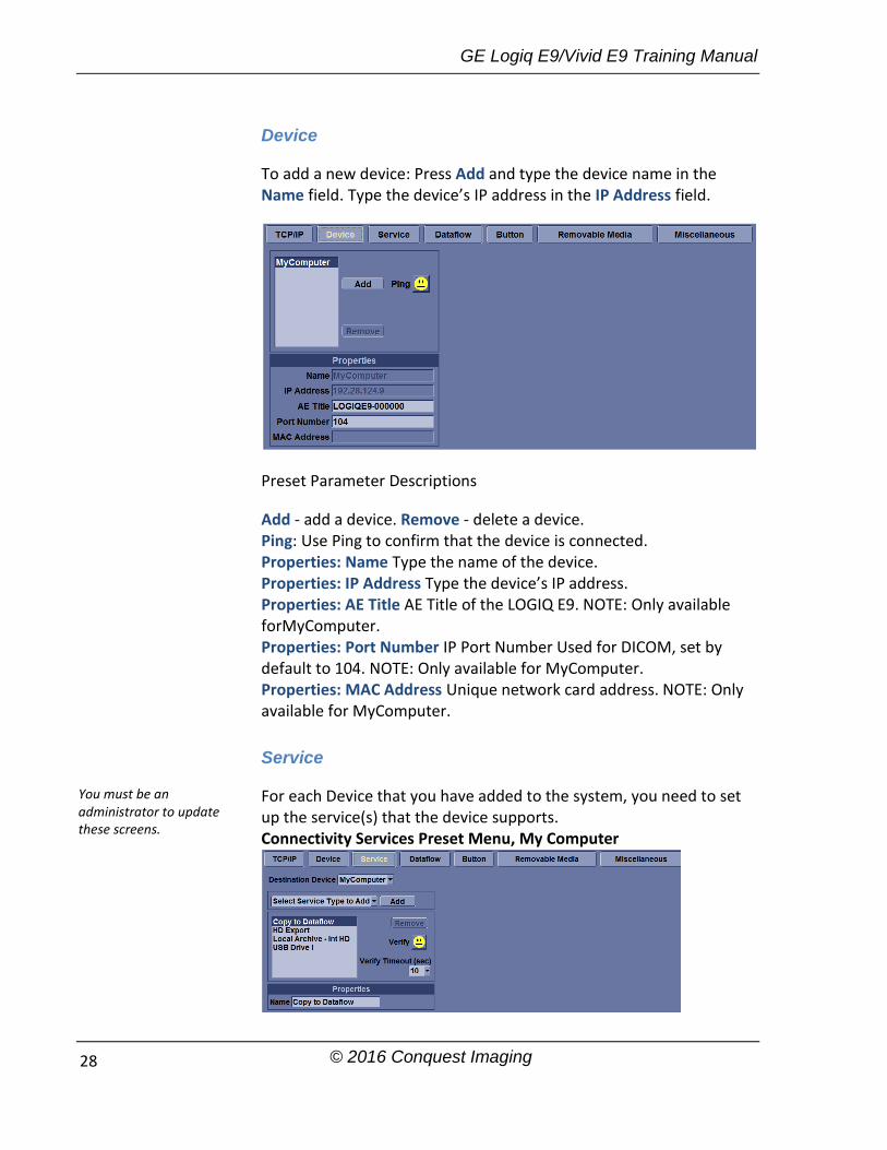
Device
To add a new device: Press Add and type the device name in the Name field. Type the device’s IP address in the IP Address field.
Preset Parameter Descriptions
Add - add a device. Remove - delete a device. Ping: Use Ping to confirm that the device is connected. Properties: Name Type the name of the device. Properties: IP Address Type the device’s IP address. Properties: AE Title AE Title of the LOGIQ E9. NOTE: Only available forMyComputer. Properties: Port Number IP Port Number Used for DICOM, set by default to 104. NOTE: Only available for MyComputer. Properties: MAC Address Unique network card address. NOTE: Only available for MyComputer.
Service
For each Device that you have added to the system, you need to set up the service(s) that the device supports. Connectivity Services Preset Menu, My Computer
You must be an administrator to update these screens.
GE Logiq E9/Vivid E9 Training Manual
© 2016 Conquest Imaging 29
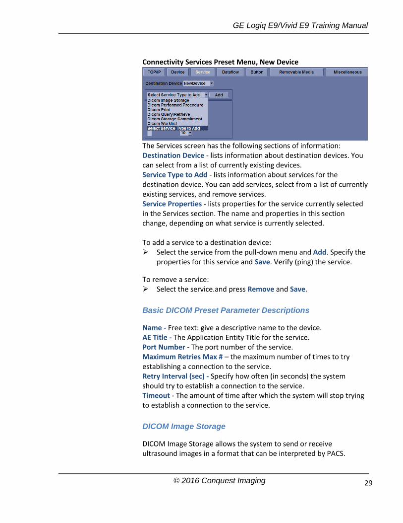
Connectivity Services Preset Menu, New Device
The Services screen has the following sections of information: Destination Device - lists information about destination devices. You can select from a list of currently existing devices. Service Type to Add - lists information about services for the destination device. You can add services, select from a list of currently existing services, and remove services. Service Properties - lists properties for the service currently selected in the Services section. The name and properties in this section change, depending on what service is currently selected. To add a service to a destination device: Select the service from the pull-down menu and Add. Specify the
properties for this service and Save. Verify (ping) the service.
To remove a service: Select the service.and press Remove and Save.
Basic DICOM Preset Parameter Descriptions
Name - Free text: give a descriptive name to the device. AE Title - The Application Entity Title for the service. Port Number - The port number of the service. Maximum Retries Max # – the maximum number of times to try establishing a connection to the service. Retry Interval (sec) - Specify how often (in seconds) the system should try to establish a connection to the service. Timeout - The amount of time after which the system will stop trying to establish a connection to the service.
DICOM Image Storage
DICOM Image Storage allows the system to send or receive ultrasound images in a format that can be interpreted by PACS.

GE Logiq E9/Vivid E9 Training Manual
© 2016 Conquest Imaging 30
DICOM Image Storage Preset Parameter Descriptions: Allow Multiframe Select to allow cine loop storage. Allow raw data Select to save data in both TruAccess (raw data) and DICOM format. Clear to save in DICOM format only. Compression Select the compression type: None, Rle, Jpeg, or Jpeg2000. Max Framerate Select the maximum frame rate: Full, 25, or 30. Color Support Select: Mixed, Gray or Color Reopen per image When selected, the storage protocol uses a new association for each image sent. Enable Structured Reporting Select for Structured Reporting. Key Image Notes Image deletion notification. ONLY available for the Direct Store Workflow and ONLY generated when there are images deleted during the exam. Selecting this lets the reader at the PACS system know which images have been deleted. An indicator is placed on deleted images with a reason, “Rejected for Quality Reasons,” for example.
DICOM Performed Procedure
DICOM Performed Procedure provides an acknowledgement that a study has been performed.
DICOM Print
DICOM Print provides the ability to send or receive ultrasound image data to DICOM printers.
GE Logiq E9/Vivid E9 Training Manual
© 2016 Conquest Imaging 31
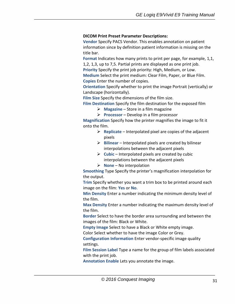
DICOM Print Preset Parameter Descriptions: Vendor Specify PACS Vendor. This enables annotation on patient information since by definition patient information is missing on the title bar. Format Indicates how many prints to print per page, for example, 1,1, 1,2, 1,3, up to 7,5. Partial prints are displayed as one print job. Priority Specify the print job priority: High, Medium, or Low. Medium Select the print medium: Clear Film, Paper, or Blue Film. Copies Enter the number of copies. Orientation Specify whether to print the image Portrait (vertically) or Landscape (horizontally). Film Size Specify the dimensions of the film size. Film Destination Specify the film destination for the exposed film
Magazine – Store in a film magazine Processor – Develop in a film processor
Magnification Specify how the printer magnifies the image to fit it onto the film.
Replicate – Interpolated pixel are copies of the adjacent pixels
Bilinear – Interpolated pixels are created by bilinear interpolations between the adjacent pixels
Cubic – Interpolated pixels are created by cubic interpolations between the adjacent pixels
None – No interpolation Smoothing Type Specify the printer’s magnification interpolation for the output. Trim Specify whether you want a trim box to be printed around each image on the film: Yes or No. Min Density Enter a number indicating the minimum density level of the film. Max Density Enter a number indicating the maximum density level of the film. Border Select to have the border area surrounding and between the images of the film: Black or White. Empty Image Select to have a Black or White empty image. Color Select whether to have the image Color or Grey. Configuration Information Enter vendor-specific image quality settings. Film Session Label Type a name for the group of film labels associated with the print job. Annotation Enable Lets you annotate the image.

GE Logiq E9/Vivid E9 Training Manual
© 2016 Conquest Imaging 32
DICOM Query/Retrieve
DICOM Query/Retrieve provides a list of patients sorted by query parameters.
If you have problems with slow responses from DICOM servers, you can try increasing the time-out in the DICOM server properties dialog: Utility -> Connectivity -> Service -> Properties-> Maximum Retries and Timeout Slow response time may result in images being re-sent automatically and low transfer rates. The retry settings can be used to make jobs retry on bad networks. When portable (off-line), use the minimum time-out and no retries as it will affect shutdown speed. DICOM Query/Retrieve Preset Parameter Descriptions: Maximum Results Specify the maximum number of patient records the system will retrieve when searching the patient database, up to 300, with the default set at 100. Search Criteria Displays the Search Criteria window, where you can enter search parameters for the system to use when searching the patient database. DICOM Query/Retrieve Search Criteria Select Search Criteria to Add Select the type of information that you want to define for search parameters. The following searches are
Note: Some PACS vendors only offer Query/Retrieve as an option. You should confirm that this service is supported.

GE Logiq E9/Vivid E9 Training Manual
© 2016 Conquest Imaging 33
allowed: Patient Name, Patient ID, Modality, Scheduled Procedure Start Date, Start Time, and End Time. Tags (at least one) The name of a tag selected to use for search criteria. Properties: Value Type the value of the Selected Tag item. For example, if you select Referring Physician’s Name in the Select Tag field, youcan enter the name of the physician in the Value field. Properties: Don’t Use Select to turn off the selected search criteria. To exclude a tag from the worklist query, select Don’t Use and then select Add to List. Add Select to add the tag and value to the list of search criteria. Remove Select to remove the tag and value from the list of search criteria. Clear Clears all tags.
DICOM Storage Commitment
DICOM Storage Commitment provides acknowledgement from the PACS server that the study has been accepted into archive. DICOM Storage Commitment Preset Parameter Descriptions: Associated Storage This selection is based on the services entered by the user.
DICOM Worklist
DICOM Worklist provides a list of patients sorted by query parameters.

GE Logiq E9/Vivid E9 Training Manual
© 2016 Conquest Imaging 34
DICOM Worklist Preset Parameter Descriptions: Max. Result Specify the maximum number of patient records you want the system to retrieve when searching the patient database. Search Criteria Displays the Search Criteria window, where you can enter search parameters for the system to use when searching the patient database. DICOM Worklist Search Criteria Preset Parameter Descriptions: Select Search Criteria to Add Select the type of information that you want to define for search parameters. The following searches are allowed: Patient Name, Patient ID, Modality, Scheduled Procedure Start Date, Start Time, and End Time. Tags (at least one) The name of a tag selected to use for search criteria. Properties: Value Type the value of the Selected Tag item. For example, if you select Referring Physician’s Name in the Select Tag field, you can enter the name of the physician in the Value field. Properties: Don’t Use Select to turn off the selected search criteria. To exclude a tag from the worklist query, select Don’t Use and then select Add to List. Add Select to add the tag and value to the list of search criteria. Remove Select to remove the tag and value from the list of search criteria. Clear Clears all tags.

GE Logiq E9/Vivid E9 Training Manual
© 2016 Conquest Imaging 35
Standard Print
Standard Print Preset Parameter Descriptions: Printer Select the printer. Rows Specify Range: 1-5. Columns Specify Range: 1-5. Orientation Specify Landscape/Portrait Top Margin (mm) Specify the top margin Range: 0-51mm Bottom Margin (mm) Specify the bottom margin Range: 0-51mm Left Margin Specify the left margin Range: 0-51mm Right Margin Specify the right margin Range: 0-51mm
Video Capture
Video Capture Preset Parameter Description: Type Specify Color, BW, or DVD Record/Pause.
Save As
Save As Preset Parameter Description Destination Specify destination device, Hard Drive or USB Flash Drive.

GE Logiq E9/Vivid E9 Training Manual
© 2016 Conquest Imaging 36
Dataflow
A dataflow is a set of pre-configured services. When you select a dataflow, the ultrasound system automatically works according to the services associated with the dataflow. The Dataflow tab allows you to select and review information about dataflows. You can also create, change, and remove dataflows.
Dataflow Preset Parameter Descriptions: Name Select the dataflow from the list. Direct Store Select to store data directly to archive (no buffer storage). Hidden Select so that this dataflow does not appear as a Dataflow on the Patient menu. Default Dataflow This dataflow will be the default when the system is initially booted. Key Object Selection: Image Deletion Notification Image Deletion Notification is available ONLY for the Direct Store Workflow and only generated when there are images deleted during the exam. This lets the reader at the PACS system know which images have been deleted. An indicator is placed on deleted images with a reason, “Rejected for Quality Reasons,” for example.
Print Button Setup
To configure the print buttons: First select the print button to configure under Physical Print Buttons on the upper, left corner of the button tab. Then select the device you want to add in the middle part of the page, under Available Input/ Outputs. Then click on the right arrow in the top right corner of the page. You can configure each print key to multiple output devices/dataflows.
Note: You must be logged on as Administrator to use the Dataflow tab.
You can only attach one DICOM service per print key (e.g., PACS and DICOM printer). Multiple DICOM devices should be configured as a dataflow
GE Logiq E9/Vivid E9 Training Manual
© 2016 Conquest Imaging 37
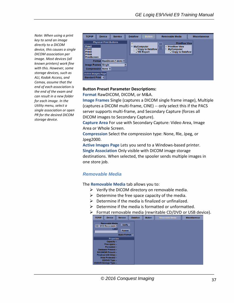
Button Preset Parameter Descriptions: Format RawDICOM, DICOM, or M&A. Image Frames Single (captures a DICOM single frame image), Multiple (captures a DICOM multi-frame, CINE) -- only select this if the PACS server supports multi-frame, and Secondary Capture (forces all DICOM images to Secondary Capture). Capture Area For use with Secondary Capture: Video Area, Image Area or Whole Screen. Compression Select the compression type: None, Rle, Jpeg, or Jpeg2000. Active Images Page Lets you send to a Windows-based printer. Single Association Only visible with DICOM image storage destinations. When selected, the spooler sends multiple images in one store job.
Removable Media
The Removable Media tab allows you to: Verify the DICOM directory on removable media. Determine the free space capacity of the media. Determine if the media is finalized or unfinalized. Determine if the media is formatted or unformatted. Format removable media (rewritable CD/DVD or USB device).
Note: When using a print key to send an image directly to a DICOM device, this causes a single DICOM association per image. Most devices (all known printers) work fine with this. However, some storage devices, such as ALI, Kodak Access, and Cemax, assume that the end of each association is the end of the exam and can result in a new folder for each image. In the Utility menu, select a single association or open PR for the desired DICOM storage device.

GE Logiq E9/Vivid E9 Training Manual
© 2016 Conquest Imaging 38
Verify Select to verify DICOM directory on removable DICOM disk. Verify the free space of the media.
Verify that the media is finalized or unfinalized.
Verify that the media is formatted or unformatted.
Format Select to format removable media. Quick Format Check this box to format the media quickly, If you uncheck this box, the media is formatted with a full format. New media should always be formatted with a full format. Removable Media Select the removable media to format or verify. Label Type a label for a new removable media (free text).
Formatting Removable Media
Select the removable media from the Media list.
Type a name for the removable media in the Label field.
Do not use any of the following characters for labelling:
\ / : ; . , * < > | + = [ ]
Select Format. Confirm OK or Cancel. An information window confirms when the format has been completed. Select OK to exit.
Miscellaneous
The Miscellaneous tab allows you to configure system behavior related to patient management and print and store options. You can specify default system functionality, such as whether patient ID is required when you archive data, or if the system should automatically search the archive for a patient when you enter patient data.
Note: Select Full Format (do not check Quick Format box) when formatting a new MOD for the first time
GE Logiq E9/Vivid E9 Training Manual
© 2016 Conquest Imaging 39
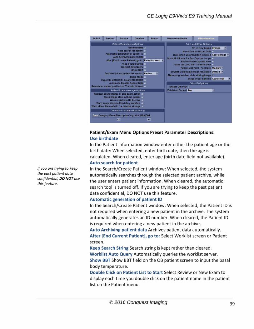
Patient/Exam Menu Options Preset Parameter Descriptions: Use birthdate In the Patient information window enter either the patient age or the birth date: When selected, enter birth date, then the age is calculated. When cleared, enter age (birth date field not available). Auto search for patient In the Search/Create Patient window: When selected, the system automatically searches through the selected patient archive, while the user enters patient information. When cleared, the automatic search tool is turned off. If you are trying to keep the past patient data confidential, DO NOT use this feature. Automatic generation of patient ID In the Search/Create Patient window: When selected, the Patient ID is not required when entering a new patient in the archive. The system automatically generates an ID number. When cleared, the Patient ID is required when entering a new patient in the archive. Auto Archiving patient data Archives patient data automatically. After [End Current Patient], go to: Select Worklist screen or Patient screen. Keep Search String Search string is kept rather than cleared. Worklist Auto Query Automatically queries the worklist server. Show BBT Show BBT field on the OB patient screen to input the basal body temperature. Double Click on Patient List to Start Select Review or New Exam to display each time you double click on the patient name in the patient list on the Patient menu.
If you are trying to keep the past patient data confidential, DO NOT use this feature.

GE Logiq E9/Vivid E9 Training Manual
© 2016 Conquest Imaging 40
Detail Mode Select to display Detail Mode, rather than Exam View, when you select the patient name in the patient list on the Patient menu. You can also type comments while in Detail Mode. Export to USB HDD: Create DICOMDIR Create DICOMDIR is a DICOM file format which contains how the directory and DICOM files structured for diagnostic portable media behave. It is important for portability between the LOGIQ E9 to PACS. Automatic Disable Patient Data Select to automatically disable patient data. If selected, locks the patient name, date of birth and gender (like Patient ID). The Factory Default for this preset is unchecked. Remember Cursor Position on the Transfer Screen To set a default cursor location on the Data Transfer screen:
Select the “Remember cursor position in the Transfer screen” preset and press Save.
On the Data Transfer screen, move the cursor to the desired field.
Exit out of the Data Transfer screen. When returning to the Data Transfer screen, the cursor is located in the selected position.
Request acknowledge of End Exam action When selected, the user is asked to confirm action when ending an examination. Warn Image Store without Patient Select to receive a warning when you press the Print key without an active patient. Warn Register to No Archive Select to receive a warning when you register a patient to the “No Archive” data flow. Select a different data flow for permanent storage of patient data. Warn image store to Read Only dataflow The system posts a warning message if you attempt to store images to a read-only Dataflow. Warn video titles exist in the internal storage The system posts a warning if the video titles exist on the internal DVR flash memory. Examination list window column configuration You can create new columns, remove columns, and select the information to display in a column.
Move the Trackball to highlight a column. Press Set.
Use the arrows (<< or >>) to reposition column headings.
If you want to save exams to the USB Hard drive and look at it on the PACS, the DICOMDIR is a must.

GE Logiq E9/Vivid E9 Training Manual
© 2016 Conquest Imaging 41
Print and Store Options Preset Parameter Descriptions
P [1-4] Key Sound Select None, Click, Chimes, Ding, Ding-Dong, or Whoosh. Store Dual as Dicom Only Select to always store dual images as a DICOM (secondary capture) store, rather than as Raw DICOM. Dual When Color Support is Mixed Dataflow Mixed is not available. While transferring dual images to the PACS, send black and white images as gray; send color images as color. Set up 2 services (one gray and one color), set up 2 dataflows, and set up 2 buttons. Each button needs to be tied to a different service. Store Multiframe for Sec Capture Loops Select if you want the CINE loop stored as a secondary capture. Enable Smart Capture Area Check box to select. Store 2D Loop with Timeline Data Check box to select. Patient List Print-Font Size Select font size. DICOM Multi-Frame image resolution Select Default, Medium, or Large for recalled DICOM Multi-frame Frame Cine loops. Show progress bar while storing image Select to display progress bar during image storage. Image Order Scheme Select to Direct Store images in Acquisition Order, Scan Assistant Order, or Off. Off. The clipboard on the Ultrasound system shows the image in
the order it was acquired. Therefore, re-stored images appear where you’d expect. However, on the PACS system, images appear in arrival order or in image number order.
Acquisition Order. From the Ultrasound system perspective, the same as “Off.” But on the PACS system (if based on image number order), images are displayed consistently with the way they are stored on the Ultrasound sysdtem.
Scan Assistant Order. You can define the storage order (reading order) via Scan Assistant Creator. Therefore, based on the order defined in Scan Assistant, images are re-ordered and displayed in this manner both on the Clipboard and on the PACS system.
Other ID Options Preset Parameter Descriptions: Enable Other ID “Not selected” is the Default. If selected, allow entering Other ID, such as Citizen Service Number, Burger Service Number (BSN), National Health System (NHS) number, along with patient ID information on the Patient Screen. Validation Format If the Enable Other ID preset is selected, the system validates the format of “Other ID” when an ID is entered.
Select if you want to keep the user preset for Color Photometric Interpretation while in Dual mode.

GE Logiq E9/Vivid E9 Training Manual
© 2016 Conquest Imaging 42
Choose: NHS Number *** ** *****, Letters and Numbers, Numbers, or Any (no restriction)

GE Logiq E9/Vivid E9 Training Manual
© 2016 Conquest Imaging 43
Module 5 Preventive Maintenance
Preventive maintenance procedures are very important in a clinical setting. Be sure to follow the health care facilities documentation procedures.
System Backup
System backup is very important. Backup the system anytime you are in front of it! Your backup is not complete without printouts!
The Backup/Restore function enables the user to:
Copy/Restore the patient archive.
Copy/Restore the system configuration.
The Copy/Restore system configuration feature enables the user to configure several units with identical presets, providing that the units have the same software version.
Backup Procedure for Vivid E9
To create a backup on Vivid E9 systems you must first login as admininstrator. You can log on to Vivid E9 as ‘ADM’ either using the touch screen or the keyboard.
Touch Screen: Select UtilityConfig
Keyboard: Press F2.
Both will bring up the Operator Login dialog box. By default, two users are pre-defined, USR and ADM. If you log on as USR, you will have access to do user set-up tasks such as select a printer.
If you log on as ADM, you will have access to do general set-up and service adjustments such as network and connectivity settings. The default password for ADM is ulsadm. Select ADM and enter the password (ulsadm) and select Login.
The Backup/Restore function enables the user to:
To minimize accidental loss of data, perform backup of the patient archive stored on the local hard drive at least once a week.
USR requires no password by system default. However, the facility may have set up individual passwords for different users in which case you will have to ask for a password

GE Logiq E9/Vivid E9 Training Manual
© 2016 Conquest Imaging 44
Copy/Restore the patient archive. Copy/Restore the system configuration.
The Copy/Restore system configuration feature enables the user to configure several units with identical presets, providing that the units have the same software version.
There is no backup function for the images or reports. For long-term storage, images and reports should be moved to a USB HD or to a network shared folder using the Disk management procedures.
Backup procedure:
1. Press Patient.
2. In the Search/Create patient window, select the dataflow Local Archive - Int. HD.
Dataflow Selection for Backup
3. Press Utility/Config on the Touch panel and select the category Admin -> Backup tab.
5. In the Backup tab select either:
Patient archive to backup the patient records. System configuration to copy system settings and user presets.
To minimize loss of data, perform backup of the patient archive stored on the local harddrive at least once a week.
Note: To be able to select a network share folder, the path (of type:\\server-name\share-name) must be entered in the Remote path field.

GE Logiq E9/Vivid E9 Training Manual
© 2016 Conquest Imaging 45
6. Select a removable media or a shared network folder as destination.
7. If the backup is to be stored to removable media, insert a dedicated media in the drive and select Start backup. If the media is not formatted a dialog will open:
Enter a label in the textbox for the media and click “Yes”. Only the following characters and signs can be used when labelling a media: A - Z, a - z, 0 - 9, “_” and “-”. Do not use more than eleven characters or spaces.
To reuse a backup media when performing a new archive back up you will need to re-format the media first.
8. At the end of the process, the media is ejected and the Backup completed window is displayed:
Select OK. The Backup result is displayed on the Backup tab.
You will need an empty/formatted media The system will not overwrite if there is already a backup or disk management copy on the media. An error message will be displayed and the disk ejected.
Make sure to physically label the media with an identification of the system and update the backup log.

GE Logiq E9/Vivid E9 Training Manual
© 2016 Conquest Imaging 46
Restore Procedure for Vivid E9
1. Press Utility/Config from the Touch panel and select the category Admin -> Restore tab.
2. In the Restore tab select as needed:
Patient Archive to restore the patient archive.
System Configuration to restore all system settings and user presets.
If restoring from removable media, make sure that the Restore from Source Device checkbox is selected and then select the appropriate Source Device.
3.If restore is done from a backup on a removable media, insert the media in the drive and select Restore Now.
Depending on the selection, one or two restore confirmation windows are displayed:
You can select one or several items under the System Configuration rather than restoring the entire system configuration.

GE Logiq E9/Vivid E9 Training Manual
© 2016 Conquest Imaging 47
Ensure that the correct source is selected and select OK.
If connectivity configuration settings are restored the following information window is displayed:
Select OK.
The System shutdown window is displayed:
Select OK. to shut down the system.
4. Restart the system.
5. If connectivity configuration settings have been restored, make sure to save the TCP/IP settings:
Select Config/Connectivity/TCPIP and select Save settings. The system will need to be restarted again.
Don’t forget.

GE Logiq E9/Vivid E9 Training Manual
© 2016 Conquest Imaging 48
Backup Procedure for Logiq E9
Depending on the system, you can use either a CD-R, DVD-R, USB Flash Drive, or USB Hard Disk for system backup/restore.
System/Backup and Restore Preset Menu
The backup and restore procedures described in this section are divided into two parts. The first describes procedures to backup and restore patient data. The second describes procedures to backup and restore system and user-defined configurations.
1. First, save the images using EZBackup.
2. Next, perform Backup at Utility -> System -> Backup/Restore. Enable the following checkboxes under Backup:
Patient Archive Report Archive User defined configuration Service
Before deleting a patient or image from the patient screen, make sure you have saved the data by EZBackup/Backup or Export and verify that the media transfer of data was successful.
Note: The system ONLY supports CD-R / DVD-R and DOES NOT support CD-RW / DVD+R / DVD+RW / DVD-RAM.
Be sure to verify the media after writing of data, such as EZBackup, SaveAs or Export.
GE Logiq E9/Vivid E9 Training Manual
© 2016 Conquest Imaging 49
Backup Preset Parameter Descriptions
Patient Archive Select to back up patient data. Report Archive Select to back up report data. User Defined Configuration -Select to back up the user-defined configuration settings. Service Select to back up Service (iLinq and Network) settings. Backup Select to begin the backup. Media Preset Parameter DescriptionS Media Select media type to use for backup and restore EZMove Preset Parameter Descriptions Move Files Older Than in Days The system will move images older than the number of days specified here. If you enter a zero (0), then all of the images from today on will be moved. Media Select media type. Media capacity for estimate (MB) Specify the capacity of the backup media. EZBackup Preset Parameter Descriptions Reminder Dialog Interval Days Specify the number of days after the last backup that you want the system to prompt you to perform an EZBackup/EZMove procedure (only for moving images). Enable Reminder Dialog Select to activate the EZBackup/EZMove reminder pop-up dialog. Media Select media type. Media capacity for estimate (MB) Specify the capacity of the backup media. Restore Preset Parameter Descriptions Patient Archive Select to restore patient data. Report Archive Select to restore report data. User Defined Configuration Select to restore the user-defined configuration settings. Service Select to restore service iLinq and Network settings.DO NOT restore service presets on to a different LOGIQ E9 system. Only restore service presets to the same system. Restore Select to begin the restore process for the selected configuration files. Detailed Restore of User Defined Preset Parameters The detailed section of this menu allows you to restore a subset from the user defined configuration. You can selectively restore what you
This parameter for EZBackup only
This parameter for EZBackup only

GE Logiq E9/Vivid E9 Training Manual
© 2016 Conquest Imaging 50
want to restore across multiple machines. Check the parameters you want to restore, insert media, and press Restore Detailed Restore of User Defined Preset Parameter Descriptions Imaging Presets Select to restore imaging presets. Connectivity Configuration Select to restore connectivity configurations. Measurement Configuration Select to restore measurement configurations. Comment/Body Pattern Libraries Select to restore comment and body pattern configurations. Report Templates (Same software version only) Select to restore Report templates. 3D/4D Select to restore 3D/4D settings. Fast Key Select to restore Fast Key. Utility-->Application Presets Select to restore Utility--> Application presets. Custom Programs Select to restore Scan Assistant programs. All Others Select to restore all other configurations not listed in the Detailed Restore section. This includes parameters defined on the System preset menus. Restore Select to begin the restore process for the selected configuration files.
Backup and Restore Strategy: Patient Data
Use a formatted Backup/Restore disk to back up patient archives from the hard drive. Data from the Backup/Restore disk may be restored to the local hard drive using restore. Insert formatted media into the media drive and on the Touch
Panel, press Utility -> System.
On the monitor display, select Backup/Restore.
On the Backup/Restore screen Backup list, select Patient Archive and Report Archive. In the Media field, select media.
Select Backup.As the system performs the backup, status information is displayed on the Backup/Restore screen.
The restore procedure overwrites the existing database on the local hard drive. Make sure to insert the correct media.
The restore procedure overwrites the existing database on the local hard drive.
Perform backup of the patient archives stored on the local hard drive DAILY to prevent data loss.

GE Logiq E9/Vivid E9 Training Manual
© 2016 Conquest Imaging 51
Insert the media into the media drive. On the Touch Panel, press Utility -> System.
On the monitor display, select Backup/Restore. The Backup/Restore screen is displayed.
In the Restore list, select Patient Archive.
In the Media field, select the media.
Select Restore. The system performs the restore. As it proceeds, status information is displayed on the Backup/Restore screen.
Cleaning the Air Filters
Clean the system's air filters to ensure that a clogged filter does not cause the system to overheat and reduce system performance and reliability. GE recommends the filters be cleaned quarterly. The Logiq E9 systems have two air filters which need to be cleaned. The top air filter is located on the back of the Logiq E9 below the power cord and the bottom air filter is located underneath.
Cleaning the Trackball Vivid E9 (OP-5)
The optical trackball of the more recent systems (OP-5) can be cleaned from the outside rather than disassembling the OP.
When cleaning is needed:
1.) Power OFF the Vivid E9.
2.) Place your fingers onto the Top Locking Plate.
3.) Rotate the Top Locking Plate counterclockwise until it can be removed from the keyboard.
4.) Lift off the Top Locking Plate including the Rubber Dust Filtering Ring and trackball from the keyboard.
5.) Wipe off any oil or dust from the trackball using a cleaner or dry cloth.
You cannot restore the data between systems with different software versions.
Note: If you are not logged in with administrator privileges, the Operator Login window is displayed. Log on with administrator privileges.

GE Logiq E9/Vivid E9 Training Manual
© 2016 Conquest Imaging 52
6.) Wipe off any oil or dust from the trackball housing, rollers, etc., using a cleaner or cotton bud.
7.) Insert the trackball into the housing.
8.) Place the Top Locking Plate including the Rubber Dust Filtering Ring back on the OP and lock it by rotating it clockwise.
Test the Trackball:
Power up the Vivid E9 and check that the trackball now works as intended.
NOTE: Plastic hood is not supposed to be flush due to curvature on the panel.

GE Logiq E9/Vivid E9 Training Manual
© 2016 Conquest Imaging 53
Module 6 General Safety Precautions
This section is not intended to be an all inclusive safety procedure guide. It is only brief overview of best practices that applies to all health care facilities and types of medical equipment. You should be familiar with the policies and procedures of the facility where you work AND the safety precautions and procedures described in the manufacturer’s documentation for a particular OEM.
Electrical Safety
The system is a Class I medical device with Type BF and Type CF isolated patient-applied parts. Only CF isolated transducers can be used for invasive (internal) exams.
The following are warnings recommended by the manufacturer:
Grounding prevents shock hazards. The chassis is grounded with a three wire plug and cable which must be plugged into a grounded outlet.
Never connect the system using a power strip or extension cord.
The ultrasound system should never be connected to the same circuit as life-support devices.
All devices that have patient contact: transducers, ECG leads and pencil probes that are not specifically labeled as defibrillation proof must be removed from contact with the patient before defibrillation.
Non-medical peripherals such as printers should not be used within 1.5 meters (5ft) of a patient unless the device is powered with an isolated outlet on the back of the system or an isolated transformer that meets medical safety standards; IEC 60601-1.
Wrist straps should not be worn when working on a system when the power turned on. The +5 Vdc supply is a very-high current supply. Use caution when troubleshooting.

GE Logiq E9/Vivid E9 Training Manual
© 2016 Conquest Imaging 54
Electromagnetic Interference
Electromagnetic Interference (EMI) between wireless electronic transmitting devices and medical equipment can cause degradation of the ultrasound image. The system is in compliance with existing EMI/EMC requirements. However, the use of this system in proximity of an electromagnetic field can cause degradation of the ultrasound image at times. Review the environment in which the system is being used, to identify possible sources of radiated emissions. Sources of these emissions can be from electrical devices used in the same or adjacent room. Communication devices that transmit or receive RF signals; cellular phones, pagers, radio, TV, or microwave transmission equipment located nearby can cause these emissions. If EMI from an outside source is causing disturbances, you may need to relocate your system. Electrosurgical units (ESUs), MRI’s and many other medical devices introduce radio frequency (RF) electromagnetic fields to the environment. Because ultrasound imaging frequencies are in the RF range, ultrasound transducer circuits are also susceptible to RF interference. For example, the noise generated by an ESU in use can easily impair or eliminate the ultrasound’s ability to capture an image. Some measures to reduce the chance of EMI interference include:
Three-meter rule – no powered on cell phones, or pagers within three meters of the system while in operation.
Locate the system away from other imaging equipment such as MRI’s that produce strong electromagnetic fields.
Electrostatic Discharge ESD Precautions
Electrostatic discharge (ESD), commonly referred to as a static shock, is a naturally occurring phenomenon. Electrical charges naturally build up on individuals and can create static shocks. The human body can build up a charge as high as 25,000 volts, therefore a discharge from a system user or patient to the ultrasound system can cause damage to the system or transducers. Digital ICs are particularly vulnerable. Low humidity is a condition that favors the build-up of electrostatic charge.
The following are the most common causes of ESD:
Moving equipment Moving people

GE Logiq E9/Vivid E9 Training Manual
© 2016 Conquest Imaging 55
Low humidity (hot and dry conditions) Improper grounding Unshielded cables Poor connections
Use the following precautions in order to reduce ESD:
Wrist straps Antistatic mats Antistatic spray on carpets or linoleum
Before handling a board or you can touch a grounded surface such as the power supply housing to discharge any built-up charge.
Fire Safety
The following general fire safety practices are relevant for all electrical equipment:
If there is any evidence of smoke or fire disconnect system power immediately.
On electrical or chemical fires use only extingushers that are specified for this use. Using water or other liquids is very dangerous and can lead to injury.
General Cautions
The following are general cautions that apply to all ultrasound systems:
Batteries must be handled as hazardous waste. Check that the cases are intact and the terminals are clean. Follow your facilities procedures regarding disposal should they become damaged.
If the system has been stored below 10°C allow it to reach room temperature before connecting or turning on to prevent damaged caused by internal condensation.
System transductors cannot be cleaned/decontaminated by any sort of heat process. Refer to manufacturer’s specifications and hospital procedures for the particular transducer.

GE Logiq E9/Vivid E9 Training Manual
© 2016 Conquest Imaging 56
Module 7 Troubleshooting
This module covers common troubleshooting tools and procedures for the E9 systems.
Normal Power On/Boot Sequence
The following describes the normal power on/boot sequence for the E9 systems
The system has two power switches:
The Circuit Breaker Switch is located on the back of the system
next to the power cord plug-in. This allows to the system power supply to power up but does not turn on the system itself.
The On/Off button is located on the user control panel at the front of the system. This switch initates system Bootup.
Connect AC (mains) Power to the Vivid E9/Logiq E9
Before connecting AC Power to the ultrasound unit you should perform the following preliminary checks of the power cord, voltage levels and compliance with electrical safety requirements.
Ensure that the wall outlet is of appropriate type, and that the Mains Circuit Breaker is turned off.
Verify that the power cable is without any visible scratches or any sign of damage.
Verify that the on-site mains voltage is within the limits indicated on the rating label near the circuit breaker on the rear of the unit.
Connect the Power Cable’s to the power Inlet at the rear of the unit and lock the plug into position with the ACC Clamp.
Note: a probe should be connected to the system or the system will boot up in no mode.
Note: Do not cycle the circuit breaker ON-OFF-ON in less than five seconds. When turning the circuit breaker off you must wait until the ON/OFF button is no longer lit. The system should be completely de-energized before turning the circuit breaker ON again.
Note: The E9 functions on voltages from 100-240V and 50 or 60Hz. If using 220 V power, a center tapped power source is required.

GE Logiq E9/Vivid E9 Training Manual
© 2016 Conquest Imaging 57
Turn System ON
Switch ON the Mains power circuit breaker at the rear of the unit. The control panel ON/OFF button should become amber. You should also hear a “click” sound from the relays in the AC Power supply and the unit is ready to boot. The ON/OFFbutton will remain amber.
Press once on the ON/OFF button on the Operator Panel to boot the unit. The ON/OFF button turns green when it is pressed.
During a normal boot sequence, you will notice that:
The unit’s ventilation fan starts on full speed, but slows down after a few seconds.
Power is distributed to the peripherals, Operator Panel (Console), Monitor, FEP and BEP.
Back end processor is turned ON and begins to load the software.
The Start Screen displays on the monitor.
A start-up bar indicating the time used for software loading, is displayed on the monitor.
The software initiates and sets up the front end electronics.
The backlight in the keyboard is lit.
When the software load is complete the 2D screen is displayed on the screen, as long as a probe has been connected, or a No Mode screen is displayed, indicating that no probe has been connected.
Sleep Mode
Sleep Mode is intended to reduce the boot up time (is less than 120 seconds) on portable studies. Sleep mode saves all memory content in the hard drive and shuts down. When booting up, memory content is then restored from the HDD.
2D Screen
Sleep mode is not a substitute for a regular shutdown. Shutdown the system completely at least once a day to prevent performance issues.

GE Logiq E9/Vivid E9 Training Manual
© 2016 Conquest Imaging 58
Troubleshooting Log/Image Capture
If the system should malfunction you can capture logs by pressing the Alt+D keys simultaneously. This Alt+D function should respond even in the event of a system lock-up.
This will collect a screen capture of the monitor, system presets and several log files in a date and time stamped “.zip” file.
Depending on the system the Alt+D function collects a screen capture of the image monitor, user-defined presets, and the following logs:
Keyboard Shadow Log Error Logs Crash Log Vital Product Data DICOM Logs Windows Event Logs Diagnostic Logs Service Logs
When Alt+D is pressed you will need to enter the following information in the window that opens:
System ID serial number. Software version. System Date and time of occurrence. Sequence of events leading to issue. Is the issue repeatable? Imaging mode, probe, preset/application. Did the system lock-up? Select the destination for the log capture either formatted
storage media or the Service directory for remote viewing through InSite ExC.
To save to a CD/DVD select CD/DVD Recordable as the destination, otherwise the data will be written to the default Export/Service directory on the hard drive. The Export/Service directory is only used for InSite ExC.
Click the Store button.
The screen capture is a bitmap which eliminates the possibility of artifacts from compression.
On later system versions for CD/DVD; the system will automatically format if you insert an unformatted disk, gather logs and write it out to the disk.

GE Logiq E9/Vivid E9 Training Manual
© 2016 Conquest Imaging 59
Trouble Shooting Network Issues
The network tools include Wireshark which is a “network sniffer” that displays network traffic between the ultrasound system and other devices. It is useful for debugging connectivity issues. Its output can be saved to a file. To display the Wireshark interface press Alt-N:
In the Capture/Interfaces window press the Options button that corresponds to the IP address.
Uncheck "Capture packets in promiscuous mode" and Press Start.
Depending on the software version enter "dcm" or "dicom." In the filter bar. Wireshark indicates whether it accepts one or the other by turning the Filter dialog background green.
This network sniffer tool is available in both systems.

GE Logiq E9/Vivid E9 Training Manual
© 2016 Conquest Imaging 60
Press Apply. Once Wireshark displays DICOM traffic, you can select an individual line and expand the DICOM tree in the lower frame to view DICOM-specific data.
Capture Restart clears the current traffic display, in preparation for the next DICOM exchange.
Entries with “Reject” or “Abort” indicate issues.
To save the network traffic currently displayed, stop the capture and press File / Save As. In the pop-up, select a destination drive or folder, name the file, select both “All packets” and “Displayed” under Packet Range, and press Save.
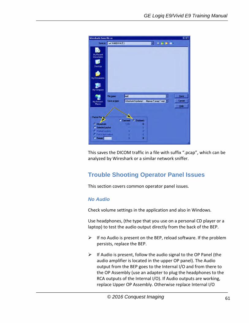
GE Logiq E9/Vivid E9 Training Manual
© 2016 Conquest Imaging 61
This saves the DICOM traffic in a file with suffix “.pcap”, which can be analyzed by Wireshark or a similar network sniffer.
Trouble Shooting Operator Panel Issues
This section covers common operator panel issues.
No Audio
Check volume settings in the application and also in Windows.
Use headphones, (the type that you use on a personal CD player or a laptop) to test the audio output directly from the back of the BEP.
If no Audio is present on the BEP, reload software. If the problem persists, replace the BEP.
If Audio is present, follow the audio signal to the OP Panel (the audio amplifier is located in the upper OP panel). The Audio output from the BEP goes to the Internal I/O and from there to the OP Assembly (use an adapter to plug the headphones to the RCA outputs of the Internal I/O). If Audio outputs are working, replace Upper OP Assembly. Otherwise replace Internal I/O
GE Logiq E9/Vivid E9 Training Manual
© 2016 Conquest Imaging 62
board.
Always measure the speakers’ impedance; it should measure approximately 7 ohms. If speakers are bad, it is possible that the amplifier on the Upper OP Assembly might be defective, too.
No Video on LCD Display
If the video is too dim, has dimmed areas or there is no video at all, replace the HV LCD inverter.
Check the cabling within the system.
If the HV LCD inverter is burnt, there is a possibility that the Digital Video Card on the PC also got damaged; in that case you can replace the Video Card.
Replace the Video Adapter inside the BEP.
Replace the Back End Processor if the problem continues.
Replace the Upper Panel Assembly.
Wrong Key Activated on the Touch Panel
Calibrate touch panel.
Replace Upper Panel Assembly.
Touch Panel Not Responding
Calibrate the Touch Panel.
Reload software.
Replace Upper Panel Assembly.
Probe Recognition
Check all the probes on all the ports. Remove all the probes, and then check each probe singly in every port. If the problems persist with all the probes, replace the GRLY

GE Logiq E9/Vivid E9 Training Manual
© 2016 Conquest Imaging 63
board. If only one probe fails to be recognized, replace the probe.
GE Logiq E9/Vivid E9 Training Manual
© 2016 Conquest Imaging 64
Module 8 Parts Replacement
This section provides procedures and information for replacing spare parts on the E9 systems. Always follow the standard ESD and safety procedures when replacing parts or modules. Pay close attention to the part number when replacing parts:
Most parts are labeled with the part number.
Always replace like for like or check compatibility.
Visually inspect all parts before installing.
Some parts are different depending on BT level and/or SW.
Some parts are only compatible with Logiq E9 or Vivid E9.
System Power Down
The system should be completely powered down before opening the chassis and beginning any parts replacement:
Press the Power button on the Control Panel to power off the system.
Select Shutdown from the touchscreen to shut down the system. The system is not fully shut down until the light on the operator panel turns off.
After the system has fully shut down switch the MAINS circuit breaker on the back of the system to OFF.
Unplug the AC power cord from wall socket.
Chassis Cover Removal
This section describes how to open up the chassis for repairs and maintanance. These should be removed in the following order:
1. Side Cover 2. Top Cover
Check the model number and other vital information before ordering parts for the system.
If the system is not fully shut-down when you switch off the mains breaker loss of data on the HD can occur.
Wait 30 seconds or so for capacitors to discharge before opening system.
If you need more detail refer to the company service manual.

GE Logiq E9/Vivid E9 Training Manual
© 2016 Conquest Imaging 65
3. Foot Rest Bumper 4. Front Cover 5. Filter Cover 6. Rear Cover
Replace the covers in reverse order.
Side Covers
The side covers are fastened with two “click” locks, located at the lower end of the cover. To remove the side covers: Insert a #1 phillips screwdriver into the rectangular hole in the
side bumper until it reaches the lock mechanism. Push the handle on the screwdriver downwards to release the lock.
Lift the cover backwards and up to remove it from the system.
Top Cover
To remove the top cover:
First remove the side covers.
Remove the two screws located near the handle and gently pull back and up.
Foot Rest Bumper
The foot rest bumper is fixed with snap locks. To remove the foot rest bumper:
Pull the foot rest bumper upwards and over the pedals to release
Side cover removal procedure is easier if you release the rear lock first.
You may need to push down the pedals in order to remove the foot rest bumper.

GE Logiq E9/Vivid E9 Training Manual
© 2016 Conquest Imaging 66
the snap locks, while freeing the side latches.
Front Cover
Follow these steps to remove the front cover:
Remove the other panels and the foot rest bumper.
Unscrew the two (2 pc) screws that fix the front cover assembly to the chassis.
Pull the upper end of the front cover out and upwards to free it from the pedals and the frame.
Back Filter Cover
To remove the filter cover:
Gently pull the filter cover out and away from the system.
To replace the Filter Cover:
Place into position and press the filter cover’s top corners until the filter cover locks engage.
In the illustration the side cover is removed to show the Side Latch. It is not necessary to remove the side cover to remove the foot rest bumper.
Inspect the Filter, and clean if necessary.

GE Logiq E9/Vivid E9 Training Manual
© 2016 Conquest Imaging 67
Rear Cover
There are four screws; two on each side of the cover. Remove the screws from both sides of the rear cover and lift it away from the chassis.
When replacing the rear cover make sure the manual release handle of the Z Mechanism extends through the TOP air vent on the rear cover.

GE Logiq E9/Vivid E9 Training Manual
© 2016 Conquest Imaging 68
Remove Bulkhead Cover
At the rear of the system, release the console’s frogleg mechanism by inserting a screwdriver into the release point and pressing until release. Pull the console out to its extended position to gain access to the screws in the next step.
Use thumbs to press upper lock tabs toward the front of the system to release the top of the Bulkhead Cover.
Pull the Bulkhead Cover away from the system.
Slots for Bulkhead Cover
XY Release point

GE Logiq E9/Vivid E9 Training Manual
© 2016 Conquest Imaging 69
Remove Handle, Left/Right Top Handle
Preparations: 1.) Power down the Vivid E9 and disconnect the Mains Power Cable. 2.) Remove the buttons below the Touch Panel. 3.) Remove the Upper Operator Panel. 4.) Remove the Lower Operator Panel.
Hatches are used to attach the top handles to the lower User Interface.
Be careful when doing this procedure. It is easy to break the plastic hatches
The screwdriver positions shown below "Release Hatches" indicate where the hatches are located.
Release Hatches
Use a thin screwdriver to release the hatches, one by one as illustrated, until you can remove the handle.
Handle Left Top / Handle Right Top reinstallation
Remove the Gel Cups (if present).
Install the Handle, Left Top / Handle, Right Top by pressing them into the lower UI Frame and replace the Gel Cups.
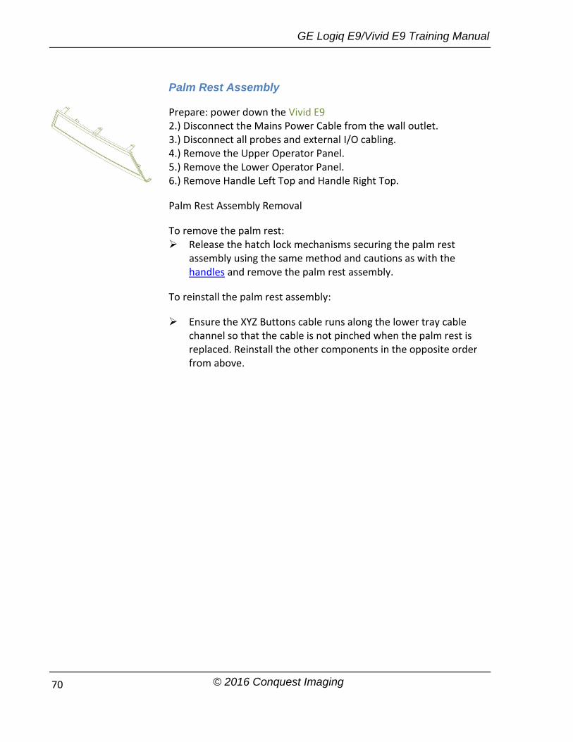
GE Logiq E9/Vivid E9 Training Manual
© 2016 Conquest Imaging 70
Palm Rest Assembly
Prepare: power down the Vivid E9 2.) Disconnect the Mains Power Cable from the wall outlet. 3.) Disconnect all probes and external I/O cabling. 4.) Remove the Upper Operator Panel. 5.) Remove the Lower Operator Panel. 6.) Remove Handle Left Top and Handle Right Top.
Palm Rest Assembly Removal
To remove the palm rest: Release the hatch lock mechanisms securing the palm rest
assembly using the same method and cautions as with the handles and remove the palm rest assembly.
To reinstall the palm rest assembly:
Ensure the XYZ Buttons cable runs along the lower tray cable channel so that the cable is not pinched when the palm rest is replaced. Reinstall the other components in the opposite order from above.
GE Logiq E9/Vivid E9 Training Manual
© 2016 Conquest Imaging 71
LCD Monitor Replacement
Prepare for replacement: Move the top console to its lower locked position. Power down the system. Disconnect all probes and external I/O cabling.
Logiq E9 LCD Monitor Replacement
Logiq E9 systems come with two types of monitors:
Original LCD Monitor (P/N 5167953) LCD Monitors used in R4 original consoles, LCD Monitor V2
(5392293-21, used in R4.x and later production)
LCD Monitor (P/N 5167953) Replacement
Tilt the LCD monitor forward to horizontal position. Unscrew the fixing screw on the rear side of the LCD monitor assembly ad remove the monitor cables cover.
Disconnect the cables to the monitor.
Remove the two clamps.
If the device is equipped with the WLAN option, remove the WLAN dongle and transfer it to the new monitor. Lift the dongle, slightly to disengage the Velcro, and pull the dongle out of the USB port. Tilt the monitor back to vertical position.
Lock the monitor back into it’s vertical position.
Loosen the four screws by turning each screw between one half and one turn counter-clockwise.
Lift the LCD Monitor assembly upwards until you can lift it away from the Monitor Bracket.
Installing the new monitor:
To be sure the system is level check that:
The system is on a level surface. The wheels are in-line.
Note: For Logiq monitor replacement check if the system uses WLAN. You may need to remove the dongle from beneath the cover of the monitor and replace it in the new monitor.
If you are replacing any of the cables, you will also need to remove two additional tie-wraps at the bracket.
It is not necessary to completely remove the screws.
Ensure the LCD Monitor is installed level with the system before tightening the four screws:

GE Logiq E9/Vivid E9 Training Manual
© 2016 Conquest Imaging 72
The LCD monitor arm lock is LOCKED.
Install the LCD monitor assembly on the monitor bracket. Verify that all four fixing screws have engaged in their slots.
Use a level if available on the monitor while you tighten the four screws.
Tilt the monitor to horizontal position and connect the cables. If the cables were replaced replace the tiewraps and cable clamps, if present.
Reinstall WLAN dongle, if the system is equipped with the WLAN option and replace the back cover.
LCD Monitor V2 (5392293-21) Replacement
Remove the two LCD cable cover fixing screws.
The LCD Cable is secured to the LCD with a retaining screw, an EMC shielded retainer and two phillips screws.
Remove the screws and retainer.
Disconnect the cable from the LCD.
Keep the LCD monitor supported and remove the two M5x20 screws and spring “lock” washers which mount the LCD to the arm assembly.
When installing the new monitor simply reverse the steps above and keep the system level by ensuring that:
The system is on a level surface. The wheels are in-line. The LCD monitor arm lock is LOCKED.
Vivid E9 LCD Monitor Replacement
The backside cover of the LCD monitor assembly covers the two cables to the monitor. To gain access to the cable connectors, first remove the LCD rear cover:
Tilt the LCD monitor forward to it is in the horizontal position.
WARNING: When removing the LCD from the arm make sure the arm assembly is in the locked position! The assembly can spring open and cause damage and potential injury.

GE Logiq E9/Vivid E9 Training Manual
© 2016 Conquest Imaging 73
Remove the two fixing screws from the back side of the LCD Monitor assembly and lift the cover.
Disconnect the two cables shown below:
Tilt the monitor back to its vertical position before removing the screws.
Lift the LCD monitor assembly upwards away from the LCD arm bracket.
Replace with the new LCD monitor.
Replacing the LCD Arm assembly
Vivid Preparations
To prepare for replacement:
1.) Power down the Vivid E9
Screws

GE Logiq E9/Vivid E9 Training Manual
© 2016 Conquest Imaging 74
2.) Disconnect the Mains power cable from the wall outlet.
3.) Disconnect all probes and external I/O cabling.
4.) Remove the LCD monitor assembly.
5.) Remove the Bulkhead cover and follow these steps to disconnect the cables from the Bulkhead board:
Disconnect the Power/USB PLUG from the Bulkhead board.
Bend the HDMI connector lock upwards, then disconnect the HDMI plug.
To remove the LCD Arm assembly:
Slide the LCD Mount Lock Handle into unlocked position.
Move the LCD arm from side to side at the same time pulling
Cables at Bulkhead
Note that in the photo the LCD mount lock handle is in the locked position. Do not adjust the nut on the LCD mount lock handle!

GE Logiq E9/Vivid E9 Training Manual
© 2016 Conquest Imaging 75
upwards, until you can lift LCD arm assembly away.
Install the LCD Arm Assembly
To install the LCD arm assembly: Carefully install the LCD arm assembly into position, first feeding
the LCD Arm cables down through the console opening. Push the LCD Mount Lock Handle into the locked position.
LCD Mount Lock Handle
Connect the LCD cables to the connectors on the bulkhead. Reinstall the bulkhead cover. Reinstall the LCD monitor.
Replacing the LCD Cables
Preparations: When preparing for the replacement, you must perform the following steps: Power down the system. 3.) Disconnect all probes and external I/O cabling. 4.) Remove the LCD Monitor. 5.) Remove the LCD Arm.
To remove the LCD Cables: Remove the two M4 x 8 screws holding the bumper cover to the
arm.
LCD Arm installed onto the UI Frame Upper
When handling the arm, use the arm lock unless the arm is being turned. Locking will help stabilize the arm.

GE Logiq E9/Vivid E9 Training Manual
© 2016 Conquest Imaging 76
Remove the bumper cover from the end of the first arm.
Remove the covers from all three arm sections of the arm assembly:
Remove the eight screws securing the first arm section cover. Remove the eight screws securing the third arm section cover.
Remove the 16 screws securing the second arm section cover with Philips screwdriver.
Third Arm Cover Removal
Second Arm Section Cover Removal

GE Logiq E9/Vivid E9 Training Manual
© 2016 Conquest Imaging 77
Cut tie wraps securing cables and remove the cable(s)
Mark the cables: After removing the cable(s) to be replaced, stretch out both the existing and replacement cable side-by-side, and transfer any markings from existing cable to the replacement cable.
Install the LCD Cables
Warning: Do not over-stretch cables. Before putting the covers on the arms, be sure the arm has full pivot motion/rotation without stressing the cables. If you are replacing more than one cable, begin with the thickest cable first!
Follow these steps to install the LCD Cables:
Holding the monitor-end of the cable and starting at the console-end of the first arm section, thread the replacement cable(s) through the arm sections toward the monitor-end.
Feed the cable through the opening opposite the arm lock mechanism side of first arm section.
Make sure the cable markings line up with the midpoint placement location for the first arm as shown below:
Feed Cable Through First Arm

GE Logiq E9/Vivid E9 Training Manual
© 2016 Conquest Imaging 78
Feed cable through opening for second arm section making sure the markings line up with the midpoint placement location for the second arm.
Feed the cable through the opening of the third arm section.
For the Video and Power cables, make sure the markings appear past the third arm LCD bracket and connect to the LCD bracket with clips shown below:
First (left) Arm Section Midpoint Location
Second Arm Section Midpoint Location
Feed Cable through Third Arm
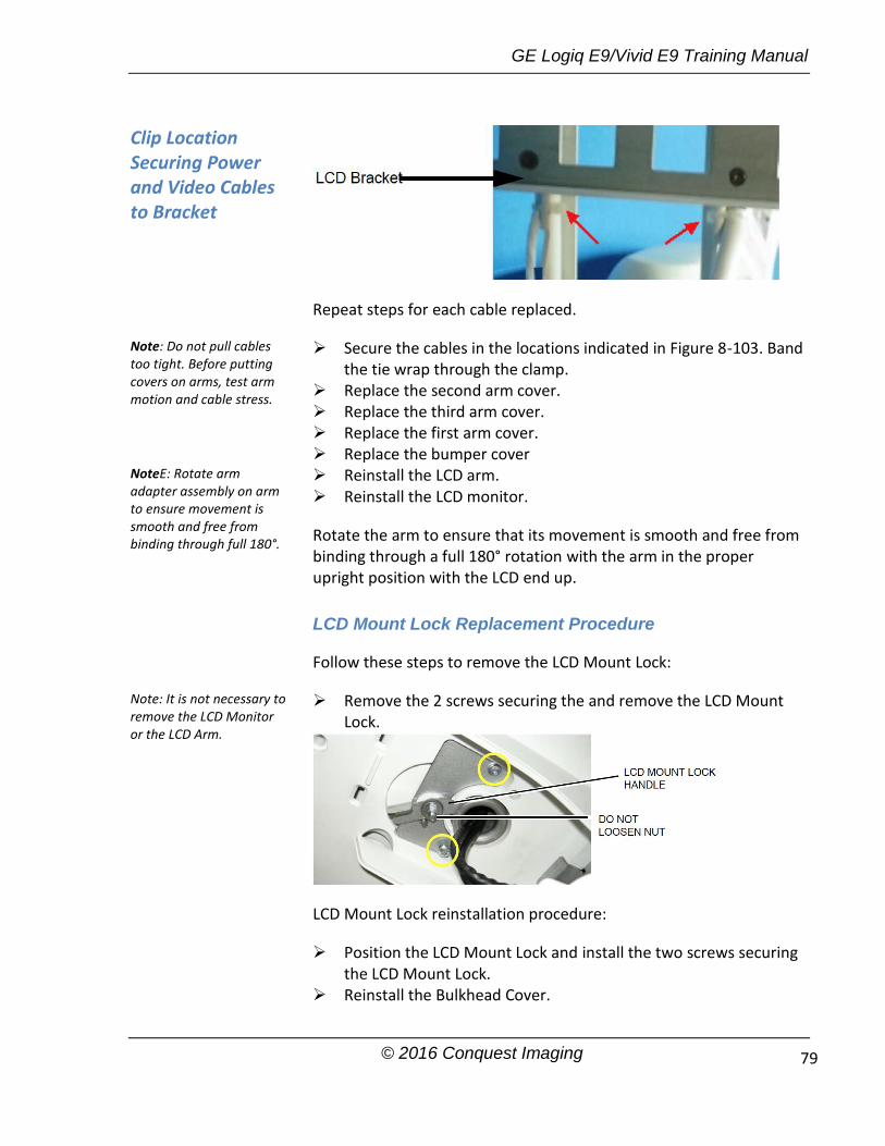
GE Logiq E9/Vivid E9 Training Manual
© 2016 Conquest Imaging 79
Repeat steps for each cable replaced.
Secure the cables in the locations indicated in Figure 8-103. Band the tie wrap through the clamp.
Replace the second arm cover. Replace the third arm cover. Replace the first arm cover. Replace the bumper cover Reinstall the LCD arm. Reinstall the LCD monitor.
Rotate the arm to ensure that its movement is smooth and free from binding through a full 180° rotation with the arm in the proper upright position with the LCD end up.
LCD Mount Lock Replacement Procedure
Follow these steps to remove the LCD Mount Lock:
Remove the 2 screws securing the and remove the LCD Mount Lock.
LCD Mount Lock reinstallation procedure:
Position the LCD Mount Lock and install the two screws securing the LCD Mount Lock.
Reinstall the Bulkhead Cover.
Clip Location Securing Power and Video Cables to Bracket
Note: Do not pull cables too tight. Before putting covers on arms, test arm motion and cable stress.
NoteE: Rotate arm adapter assembly on arm to ensure movement is smooth and free from binding through full 180°.
Note: It is not necessary to remove the LCD Monitor or the LCD Arm.

GE Logiq E9/Vivid E9 Training Manual
© 2016 Conquest Imaging 80
Replacing Upper Operator Panel/Touch Panel Assembly
Power down the system. Disconnect all probes and external I/O cabling.
To remove the Upper OP Panel/Touch Panel assembly:
Remove all five OP Panel Knobs along the base of the upper OP Panel/Touch Panel assembly,
At the rear of the Vivid E9, release the console’s XY frogleg
mechanism by inserting a screwdriver into the release point and pressing until it releases. Pull the console out to its extended position to gain access to the screws in the next step.
Remove the four screws with washers from the Operator Panel’s
back cover.
Lift the Upper OP Panel/Touch Panel assembly slightly from the bottom, and then tilt the top toward the front of the Vivid E9. There are tabs at the bottom of the Touch Panel Assembly. Pull straight up on these tabs.
Use ESD precautions!
Ensure that the OP Panel is in its uppermost position with the top LCD out of the way:
Two Screws on each side

GE Logiq E9/Vivid E9 Training Manual
© 2016 Conquest Imaging 81
Next disconnect the cables as shown below at the back of the Upper OP Panel/Touch Panel Assembly.
Lift out the Touch Screen Assembly and place it on an ESD safe surface.
Re-Install Upper OP Panel/Touch Panel Assembly
To re-install the Upper OP Panel/Touch Panel Assembly:
Place the Upper OP Panel/Touch Panel Assembly in the frame.
Ensure that all Ground cables are connected as shown below:
Connect the following cables to the Operator Panel:
1. Ribbon Cable from the Operator Panel, Lower 2. Trackball Cable from the Operator Panel, Lower 3. A/N Cable from the A/N Keyboard 4. Power/On-Off switch (part of Main Cable) in position J23 5. USB Cable 1 (part of Main Cable) in position J21 6. USB Cable 2 (part of Main Cable) in position J22
OP Grounding
Do not apply stress on the Ribbon Cable. If it is stretched the connector on Operator Panel may be damaged.

GE Logiq E9/Vivid E9 Training Manual
© 2016 Conquest Imaging 82
7. Bulkhead Board USB Cable 1 (from bulkhead position closest to the OP) in position J24
8. Bulkhead Board USB Cable 2 (from bulkhead position most far from the OP) in position J25
Install the Upper OP Panel/Touch Panel Assembly securing the five tabs and two hooks.
Install the four screws to the Back Cover from behind.
Install the five OP Panel Knobs.
Use caution not to pinch or crimp the cables when replacing the panel!

GE Logiq E9/Vivid E9 Training Manual
© 2016 Conquest Imaging 83
Replace Lower Operator Panel
Follow these steps to remove the Operator Panel:
Pull out the Alphanumeric keyboard to its extended position to get access to the screws in the next step.
Unscrew and remove the four screws used to mount the Operator Panel assembly to the Operator Panel tray.
Loosen the screws for the cables grounding on the Bulkhead Bracket and move the OP cables away from the bracket.
On the Bulkhead Bracket, loosen the ESD wire from the Lower Panel.
View from Below with Drawer Extended

GE Logiq E9/Vivid E9 Training Manual
© 2016 Conquest Imaging 84
Pull and lift the Operator Panel assembly up and away. Be careful to not damage the fingers on either side of the Lower Operator Panel and place it on an ESD safe surface.
Replacing the Vivid E9 Trackball
When preparing for the replacement, you must perform the following steps:
Power down the Vivid E9. Disconnect the Mains Power Cable from the wall outlet. Disconnect all probes and external I/O cabling. Remove the Upper Operator Panel. Remove the Lower Operator Panel
To remove the Trackball:
Unplug the cable connectors from the Trackball. Use the Hex key to remove the two fixing screws with washers.
Remove the Trackball and the Fixing Ring.
Re-Install the Trackball
To re-install the Trackball:
The Fixing Ring has small tabs on the top and bottom side, see the figure below. The tabs are used to fix the Fixing Ring in the correct position, and are positioned on different locations on the top and the bottom sides of the ring. When used for the Vivid E9, install it so the fixing screw holes on the Fixing Ring allign with the fixing screw holes on the Trackball assembly.
Reverse the procedure to re-install the lower operator panel.

GE Logiq E9/Vivid E9 Training Manual
© 2016 Conquest Imaging 85
Install the two fixing screws with washers so it locks the Trackball and Fixing Ring in the correct position.
Connect the signal cable connectors to the Trackball.
Re-Install the both the Upper and Lower Operator Panel.
Remove the Lower Operator Panel Frame
Follow these steps to remove the Lower Operator Panel Frame:
Remove the two screws securing the main cable.
Remove the five remaining screws from the bulkhead bracket and remove the bracket.

GE Logiq E9/Vivid E9 Training Manual
© 2016 Conquest Imaging 86
From underneath the Frame, pull the Main cables through the frame opening to free the upper frame and remove it.
Remove two plastic plate washers on either side of the bulkhead bracket.
Remove the Lower Operator Panel Frame.
Lower Frame Assembly Installation
Follow these steps to install the Lower Operator Panel (LOP) Frame:
Position the Lower Operator Panel Frame. Install the Upper Frame. Install the plastic plate washers on both sides of the bulkhead
bracket. Position the bulkhead bracket and install the five screws to
secure the Bulkhead Bracket. Install the XYZ buttons frame and the Palm Rest. Install the Main cable at the Lower Operator Panel end. Install the bulkhead board. Install the Lower Operator Panel. Install the Upper Operator Panel/Touch Panel Assembly. Install the LCD arm.
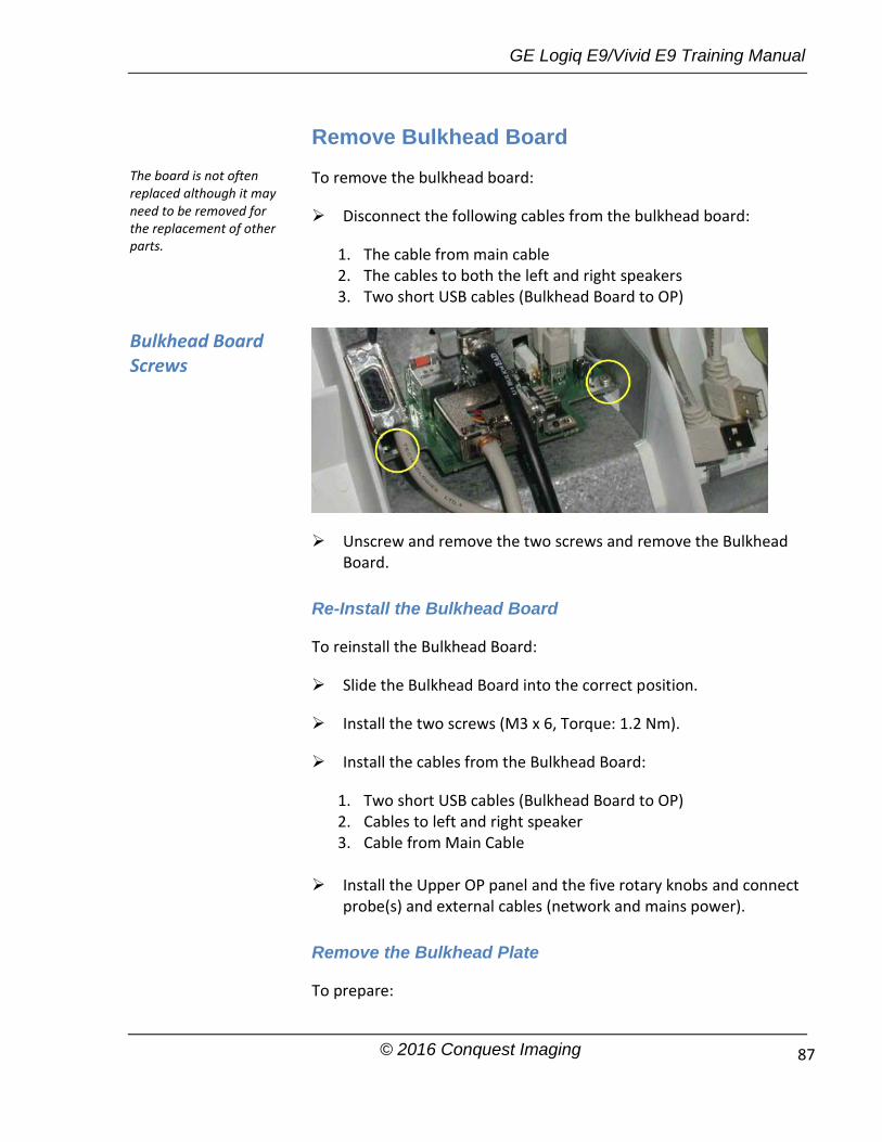
GE Logiq E9/Vivid E9 Training Manual
© 2016 Conquest Imaging 87
Remove Bulkhead Board
To remove the bulkhead board:
Disconnect the following cables from the bulkhead board:
1. The cable from main cable 2. The cables to both the left and right speakers 3. Two short USB cables (Bulkhead Board to OP)
Unscrew and remove the two screws and remove the Bulkhead Board.
Re-Install the Bulkhead Board
To reinstall the Bulkhead Board:
Slide the Bulkhead Board into the correct position.
Install the two screws (M3 x 6, Torque: 1.2 Nm).
Install the cables from the Bulkhead Board:
1. Two short USB cables (Bulkhead Board to OP) 2. Cables to left and right speaker 3. Cable from Main Cable
Install the Upper OP panel and the five rotary knobs and connect
probe(s) and external cables (network and mains power).
Remove the Bulkhead Plate
To prepare:
The board is not often replaced although it may need to be removed for the replacement of other parts.
Bulkhead Board Screws

GE Logiq E9/Vivid E9 Training Manual
© 2016 Conquest Imaging 88
Power down the Vivid E9. Disconnect all probes and external I/O cabling. Remove five OP panel knobs. Remove the upper Operator Panel. Remove the two speaker assemblies. Remove the bulkhead board. Remove the lower Operator Panel.
The bulkhead plate is used to secure the Upper UI Frame to the Lower UI Frame. To remove it:
Remove the seven fixing screws shown below.
2.) Remove the bulkhead plate and the cable clamp.
Re-install the Bulkhead Plate
Position the bulkhead plate so it aligns with the holes for the fixing screws.
Install the seven fixing screws as described below:
1. The two upper screws are M6 x 20, Torque: 8.5 Nm.
2. The next screw is M6 x 45, Torque: 8.5 Nm.

GE Logiq E9/Vivid E9 Training Manual
© 2016 Conquest Imaging 89
3. The lower left-most screw is M6 x 30, Torque: 8.5 Nm.
4. The three other lower screws are M6 x 25, Torque: 8.5 Nm. Two of the screws are also fixing the Cable Clamp.
XYZ Buttons and Button Board Replacement
These buttons are also called the XYZ Buttons. The XYZ Buttons are located on the palm rest and control the XY and Z movement.
Push one of the buttons marked “1”, and then reposition the XY (horizontal) location of the upper console. Three seconds after pushing the left button, the four motors in the XY Frog Leg lock to stabilize the console.
Toggle one of the buttons marked “2” to reposition the Z (vertical) location of the upper console.
Toggle up to raise, or down to lower, the console.
Top Console Adjustment Controls
To prepare:
System Power Down Disconnect all probes and external I/O cabling. Remove the Upper OP Panel/Touch Panel assembly. Remove the Lower Operator Panel. Remove the Handle Top Left and Handle Top Right. Remove the Palm Rest Cover.
XYZ Buttons
2 1 1 2

GE Logiq E9/Vivid E9 Training Manual
© 2016 Conquest Imaging 90
Buttons Removal Procedure
To remove the XYZ Buttons:
Disconnect the cable to the XYZ Buttons.
Gently pop the XYZ Buttons Frame out of the Palm Rest section of the Lower Op Panel frame handle.
Buttons installation procedure:
Insert the XYZ Buttons Frame into the Palm Rest section of the Lower Op Panel frame handle.
Connect the cable to the XYZ Buttons Frame.
Ensure the XYZ Buttons Frame cable runs along the Lower Op Panel cable channel so that the cable is not pinched when the Palm Rest is replaced.
Replace the Palm Rest. Replace the Handle Top Left and Handle Top Right. Replace the Lower Operator Panel. Replace the Upper OP Panel/Touch Panel assembly.
Button IF Board Replacement
To Prepare:
System Power Down Disconnect all probes and external I/O cabling. Remove the Upper OP Panel/Touch Panel assembly. Remove the Lower Operator Panel. Remove Handle Left Top and Handle Right Top. Remove the Palm Rest Cover.

GE Logiq E9/Vivid E9 Training Manual
© 2016 Conquest Imaging 91
Button IF Board removal procedure: Disconnect all the five (5x) connectors from the board.
Push the TABs away to release the board.
Remove the board.
Button IF Board installation procedure: Install the Button IF Board into the UI Frame, Lower by pressing it
under the small hooks.
Ensure that the XYZ Buttons Frame cable runs along the Lower Op Panel cable channel so that the cable is not pinched when the Palm Rest is replaced.
XYZ Mechanism Frog Legs
Before replacement you may want to try adjusting the XYZ mechanisms. See the Operator Panel Adjustments section in the System Adjustments Module of this training manual.
When preparing for the replacement, you must perform the following steps:
Power down the system. Disconnect all probes and external I/O cabling. Remove the LCD Rear Cover. Remove the LCD Monitor assembly. Remove the LCD Arm assembly. Remove the Operator Panel, Upper. Remove the Operator Panel, Lower. Remove the Bulkhead Board. Remove the Bulkhead Plate. Remove the Upper Frame Assembly. Remove the Lower Frame Assembly.
Pull the console out to its extended position to gain access to the Park Lock Mechanism screws in the next step.
Frogleg with the operator panels removed:
In most cases it is easier and more economical to replace the entire Frog legs unit rather than to troubleshoot and repair the unit itself.

GE Logiq E9/Vivid E9 Training Manual
© 2016 Conquest Imaging 92
Remove the four screws for the XY (Frogleg) mechanism and remove the XY mechanism.
XY Mechanism Installation Procedure
Position the XY mechanism so it aligns with the holes for the four fixing screws and install the four fixing screws.
Install the Lower Frame Assembly. Install the Upper Frame Assembly. Install the Bulkhead Plate. Install the Bulkhead Board. Install the Operator Panel, Lower. Install the Operator Panel, Upper. Install the LCD Arm assembly. Install the LCD Monitor assembly. Install the LCD Rear Cover.
Note: Ensure that Bumper Z enters the slide at the back, before tighten the screws.

GE Logiq E9/Vivid E9 Training Manual
© 2016 Conquest Imaging 93
XY Park Lock Replacement
To Prepare:
Unlock the XY Park Lock, either by using the release knobs or by manually releasing the lock:
At the rear of the Vivid E9, release the console’s XY mechanism by inserting a screwdriver into the release point and pressing until release.
XY Park Lock Removal
Remove the four screws and carefully pull out the XY Park Lock assembly.
Disconnect the cable at the connector and remove the XY Park Lock assembly.
Verify that the XY locks and unlocks as intended.
If needed, adjust the locking mechanism as described in: Operator Panel Adjustments.
XY Release point
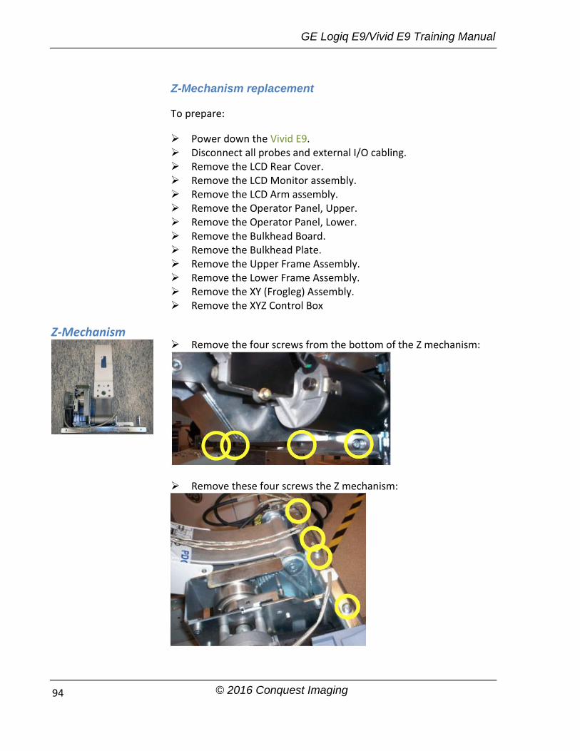
GE Logiq E9/Vivid E9 Training Manual
© 2016 Conquest Imaging 94
Z-Mechanism replacement
To prepare:
Power down the Vivid E9. Disconnect all probes and external I/O cabling. Remove the LCD Rear Cover. Remove the LCD Monitor assembly. Remove the LCD Arm assembly. Remove the Operator Panel, Upper. Remove the Operator Panel, Lower. Remove the Bulkhead Board. Remove the Bulkhead Plate. Remove the Upper Frame Assembly. Remove the Lower Frame Assembly. Remove the XY (Frogleg) Assembly. Remove the XYZ Control Box
Remove the four screws from the bottom of the Z mechanism:
Remove these four screws the Z mechanism:
Z-Mechanism

GE Logiq E9/Vivid E9 Training Manual
© 2016 Conquest Imaging 95
Lift Z Mechanism away.
XYZ Control Assembly Replacement
To prepare: Power down the Vivid E9. Disconnect the Mains Power Cable from the wall outlet. Disconnect all probes and external I/O cabling. Remove the Left Side Cover. Remove the Rear Cover. Remove the Top Cover.
XYZ Control Assembly removal procedure:
Disconnect the cables to the XYZ Control Assembly.
Unscrew and remove two (2x) screws.

GE Logiq E9/Vivid E9 Training Manual
© 2016 Conquest Imaging 96
Pull the top of the XYZ Control Assembly forwards, up and away from the bracket.
XYZ Control Assembly installation procedure: Thread the XYZ Control Assembly into position. Install the three screws at the top, rear. (M6x16 sunken. Torque:
9.8 Nm.) Install the two remaining screws on the top. (M4x8, sunken.
Torque: 4.9 Nm.) 4.) Connect the cables to the XYZ Control Assembly. 5.) Install the Top Cover. 6.) Install the Rear Cover. 7.) Install the Left Side Cover.
Main Power Suppy Replacement
The Logiq E9 has two types of power supllies the PS Lamba and the Cherokee/Mitra. The mounting is the same for both devices but the connectors are different. It is possible to replace the fan assembly and the 4D Motor Controller (4D MC) motor of the Cherokee/Mitra without replacing the entire MPS unit.
The Vivid E9 power supply does not contain any FRUs and must be replaced entirely if it becomes defective. There are several versions so be sure to determine the correct part number for your system before ordering.
To prepare for MPS replacement perform the following steps:
System Power Down Disconnect all probes and external I/O cabling. Remove both Side Covers. Remove the Top Cover. Remove the Filter Cover. Remove the Rear Cover.
Disconnect the battery cable from EPS or CB
Vivid E9 Main Power Supply Replacement
Follow these steps to remove the MPS:

GE Logiq E9/Vivid E9 Training Manual
© 2016 Conquest Imaging 97
Disconnect the cables from the top of the power supply.
Remove the three screws that secure the MPS.
Ease the MPS away from the fang bracket.
Pull/slide the entire MPS backwards until the connectors to the FEP/Backplane are unseated and lift the MPS away.
Logiq E9 Main Power Supply Replacement
Follow these steps to remove the MPS:
Disconnect the MPS cable and all cables from the top of the MPS:
AC output to peripherals, printer Power to BEP USB
Remove the three screws that secure the MPS with a 5 mm Allen wrench and ease the MPS away from the fang bracket.
Carefully pull the entire MPS backwards until the connectors to the Card Cage/Backplane are unseated.
If the 4D Motor Controller option is installed, you will need to disconnect the USB Cable from J28 on the BEP.
To replace the new MPS:
If needed, remove the 4D motor controller from the PS and install it in the replacement Power Supply before procceding
The 4D MC will also have to be transferred to the replacement MPS.

GE Logiq E9/Vivid E9 Training Manual
© 2016 Conquest Imaging 98
Make sure the GFI PCIe cable is routed behind the MPS fang as shown on the left. This is for the GFI Configuration only. MRX systems do not have this cable.
Slide the MPS forward to seat the connectors on the card cage.
Engage the tab onto the Fang and install the three screws that secure the MPS with a 5 mm Allen wrench (Torque: 10 Nm {7.4 lb-ft}).
Replace all cables and covers in reverse order of MPS removal procedure.
Back End Processor (BEP)
There are several versions of the BEP for both systems. Each BEP version has internal FRU’s such as HDD, I/O board, Battery Pack. We will not cover all permutations in this manual. Please refer to the GE parts replacement documentation for correct parts when preparing to replace BEP or BEP sub-component parts:
http://www3.gehealthcare.com/en/Support/Support_Documentation_Library
Logiq E9 Vivid E9
BEP w/ EPS for R1.x.x and R2.x.x:
For GFI configurations.
For Phase I and BT 2010 systems.
BEP – MRX w/ EPS for R3.x.x:
For MRX configurations.
For BT 2011 only systems.
Not backward compatible.
Requires new I/O board.
New PCIe cable for MRX.
BEP for BT’09 (4D):
Has same 4D video card as V7.
Requires SW v108.0.0 and higher.
BEP for BT’11:
BEP without 4D.
Requires SW v110.0.0 or higher.
Optional / new 4D video card (NVIDIA FX 1800) to handle the 4D feature.
Logiq E9 and. Vivid E9 BEPs are not compatible with each other.
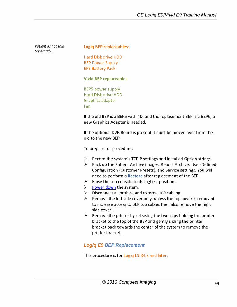
GE Logiq E9/Vivid E9 Training Manual
© 2016 Conquest Imaging 99
Logiq BEP replaceables:
Hard Disk drive HDD BEP Power Supply EPS Battery Pack
Vivid BEP replaceables:
BEP5 power supply Hard Disk drive HDD Graphics adapter Fan
If the old BEP is a BEP5 with 4D, and the replacement BEP is a BEP6, a new Graphics Adapter is needed.
If the optional DVR Board is present it must be moved over from the old to the new BEP.
To prepare for procedure:
Record the system’s TCPIP settings and installed Option strings. Back up the Patient Archive images, Report Archive, User-Defined
Configuration (Customer Presets), and Service settings. You will need to perform a Restore after replacement of the BEP.
Raise the top console to its highest position. Power down the system. Disconnect all probes, and external I/O cabling. Remove the left side cover only, unless the top cover is removed
to increase access to BEP top cables then also remove the right side cover.
Remove the printer by releasing the two clips holding the printer bracket to the top of the BEP and gently sliding the printer bracket back towards the center of the system to remove the printer bracket.
Logiq E9 BEP Replacement
This procedure is for Logiq E9 R4.x and later.
Patient IO not sold separately.
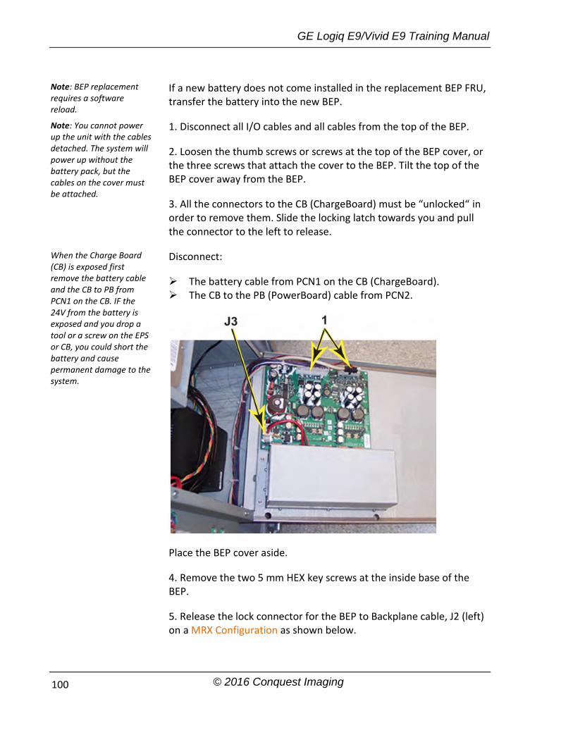
GE Logiq E9/Vivid E9 Training Manual
© 2016 Conquest Imaging 100
If a new battery does not come installed in the replacement BEP FRU, transfer the battery into the new BEP.
1. Disconnect all I/O cables and all cables from the top of the BEP.
2. Loosen the thumb screws or screws at the top of the BEP cover, or the three screws that attach the cover to the BEP. Tilt the top of the BEP cover away from the BEP.
3. All the connectors to the CB (ChargeBoard) must be “unlocked“ in order to remove them. Slide the locking latch towards you and pull the connector to the left to release.
Disconnect:
The battery cable from PCN1 on the CB (ChargeBoard). The CB to the PB (PowerBoard) cable from PCN2.
Place the BEP cover aside.
4. Remove the two 5 mm HEX key screws at the inside base of the BEP.
5. Release the lock connector for the BEP to Backplane cable, J2 (left) on a MRX Configuration as shown below.
Note: BEP replacement requires a software reload.
Note: You cannot power up the unit with the cables detached. The system will power up without the battery pack, but the cables on the cover must be attached.
When the Charge Board (CB) is exposed first remove the battery cable and the CB to PB from PCN1 on the CB. IF the 24V from the battery is exposed and you drop a tool or a screw on the EPS or CB, you could short the battery and cause permanent damage to the system.

GE Logiq E9/Vivid E9 Training Manual
© 2016 Conquest Imaging 101
Or, the Backplane cable, J3 (right) and J5 PCIe to the Card Rack on a GFI Configuration, using a BEP6 as shown below. Keep the cable to transfer to the replacement BEP.
6. Slide the entire BEP away from the system approximately one inch, and finish removing the printer bracket then slide the entire BEP chassis out of the system.
7. You will need to remove the following parts from the BEP, to reinstall in the replacement BEP:
Option Dongle
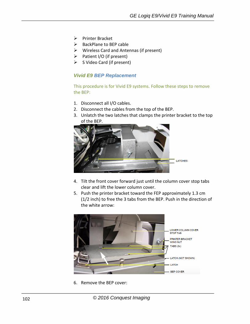
GE Logiq E9/Vivid E9 Training Manual
© 2016 Conquest Imaging 102
Printer Bracket BackPlane to BEP cable Wireless Card and Antennas (if present) Patient I/O (if present) S Video Card (if present)
Vivid E9 BEP Replacement
This procedure is for Vivid E9 systems. Follow these steps to remove the BEP:
1. Disconnect all I/O cables. 2. Disconnect the cables from the top of the BEP. 3. Unlatch the two latches that clamps the printer bracket to the top
of the BEP.
4. Tilt the front cover forward just until the column cover stop tabs clear and lift the lower column cover.
5. Push the printer bracket toward the FEP approximately 1.3 cm (1/2 inch) to free the 3 tabs from the BEP. Push in the direction of the white arrow:
6. Remove the BEP cover:

GE Logiq E9/Vivid E9 Training Manual
© 2016 Conquest Imaging 103
Loosen the BEP cover’s fixing screw(s): BEP6 has two finger screws on the top of the BEP Cover. Newer versions of the BEP5 have three Phillips screws, one on
the top and one on each side of the BEP Cover. Older BEP5 have one finger screw at the top of the BEP cover.
Tilt the top of the BEP cover away from the BEP and set the cover aside.
7. Remove the Printer Bracket from the BEP. 8. Remove the two hex key screws at the inside base of the BEP. 9. Reach inside the BEP and disconnect the Boundary Scan Cable
from the FEP Backplane Connector. It is available through a cut out in the BEP’s rear cover.
10. Slide the entire BEP out of chassis. Note: If a DVR broad is installed, remove it from the existing BEP and install it in the replacement BEP.
Note: If 4D is installed: If you change from BEP6 to a new BEP6 or from a BEP5 to a new BEP5 you can move the graphics adapter If you remove a BEP5, and the new BEP is a BEP6, you will need to order a new BEP6 compatible graphics adapter.

GE Logiq E9/Vivid E9 Training Manual
© 2016 Conquest Imaging 104
Front End Parts Replacement
The term front end as whole refers to the input and signal processing side of the system including probes, signal relays, ADC/DAC
Vivid E9 Front End Processor (FEP)
To prepare:
Power down the Vivid E9 Disconnect all probes and external I/O cabling. Remove the Right Side Cover
First remove the FEP cover. An EMI cover is used to ground the PCIe (GFI) cable to the FEP cover:
Unscrew the fixing screw for the cover for the PCIe (GFI) cable and remove the cover for the PCIe cable. Shown on the left. Unplug the PCIe cable and unscrew the FEP Cover’s ten fixing screws.

GE Logiq E9/Vivid E9 Training Manual
© 2016 Conquest Imaging 105
Use top and bottom ejectors on GRLY board to slightly pull out front planes.
Use last GTX board and repeat same process as GRLY.
The card connectors have color-keys to prevent installation in an incorrect rack position. If the system is powered on with a card placed in the wrong position, the VIVID E9 will be destroyed.

GE Logiq E9/Vivid E9 Training Manual
© 2016 Conquest Imaging 106
Repeat those steps until the two XD_Bus boards release from remaining FEP boards.
Gently release each of XD_Bus boards from connectors on GRLY and GTX.
Be sure to place boards on ESD safe surface.

GE Logiq E9/Vivid E9 Training Manual
© 2016 Conquest Imaging 107
Module 9 System Adjustments
This module covers adjustments that can be made to the GE E9 systems.
Touch Screen Calibration
The Touch Screen Calibration is found on the Operator Panel Test Dialog. Follow these steps to open the Operator Panel Test Dialog:
Select Config (F2).
Log on as ADM and select System > Test.
Select Operator Panel Test. This will open the Operator Panel Test Dialog:
The Calibrate button is used to start to calibrate the position of the touch sensitive area on the touch screen relative to the graphic artwork.
Follow these steps to calibrate the Touch screen:

GE Logiq E9/Vivid E9 Training Manual
© 2016 Conquest Imaging 108
Select Calibrate. The Touch screen goes blank and display a cross in the screen’s upper left corner.
Put your finger on the centre of the cross and press slightly. This calibrates this point and the cross moves to the next point on the screen. Continue until all five points on the screen have been calibrated.
Select Done.to complete the calibration.
DC Offset Calibration
This procedure calibrates each ADC channel of the GRX inputs. The system calibrates the ADC to zero output when there is no signal on the input. These bias voltages are stored in the BEP.
When to do a DC Offset Calibration
You will need to do a DC Offset Calibration when:
Installing a new E9 system. System software has been updated or replaced. DRX board(s) or a MRX board has been interchanged. A DRX board(s) or a MRX board has been replaced. The Back End Processor has been replaced.
DC Calibration Procedure
Disconnect all connected probes. Power on the E9.
Logiq E9
On the Touch Panel, select Utility > Service to access CSD.
Log in as GE Service, enter the current password.
Select Diagnostics tab.
Select Service >
Vivid E9
Select the InSite ExC icon (GE phone icon) to display the InSite ExC menu.
Select Service Desktop.
Select the Diagnostics tab.
Open the Analog Receive
GE Logiq E9/Vivid E9 Training Manual
© 2016 Conquest Imaging 109
Diagnostics.
Select the “+” before Service Diagnostics folder to open the list of choices.
Select the “+” before Analog Receive to open the test choices for the analog receiver.
Select DC Offset Calibration and then follow the on-screen instructions.
folder.
Select Execute to run the calibration.
After completing the calibration, you must restart the system.
Operator Panel Adjustments
This section covers adjustments to the operator panel XYZ mechanisms.
Using the Park Lock Properly
Before performing any adjustments or replacements it is important to be sure the user understands the following if they are experiencing problems with the XY park lock function. You should make sure they know they should:
Apply the brakes. The locking mechanism does not engage if the device can move when trying to park the console.
Push the release button and gently guide the console into the locked position until the lock is engaged.
They should not lean on or apply any weight on the console. If the console is not in the normal resting position, the lock will not engage when trying to park it.

GE Logiq E9/Vivid E9 Training Manual
© 2016 Conquest Imaging 110
Normal Operator Panel XY Movement
When the Operator Panel is in the locked position if you press the left button (lock) of the Frogleg Controls, it will cause the motorized park lock to release and momentarily releases the brakes in the froglegs permitting the OP to move in the XY direction.
When the console is not locked (floating) the lock button will only release the brakes in the froglegs to allow easy movement.
The lock button must be pushed to move the OP into the locked position.
When the lock button is pressed and the console is pushed back into the locked position, the U-bolt mechanically engages with the park lock. Pushing the lock button only releases the brakes, to allow the OP to be moved easily into the park lock.
The user can proceed to park the Operator Panel or to leave it un-parked.
Notice that ONCE the user selects shutdown in the Monitor, the two buttons (Z-motion and XY-motion) are disabled. The brakes on the XY mechanism are released the XY movement is free but the Z-motion is disabled. If the user wants to adjust the Z mechanism after shutdown, they will need to use the handle in the back of the unit.
Logiq E9 Lock & Positioning Buttons
Once the OP is in the lock position as the lock button is released, you will hear the sound of the park lock rotating to engage the U-bolt.
For R4, at shutdown, a message appears that tells the user that the Operator Panel is not parked.
1.) U-bolt 2.) Brakes (one inside each of the four XY arms) 3.) Park Lock (engages U-bolt)
1
2
3
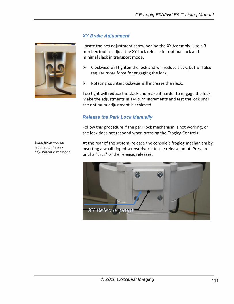
GE Logiq E9/Vivid E9 Training Manual
© 2016 Conquest Imaging 111
XY Brake Adjustment
Locate the hex adjustment screw behind the XY Assembly. Use a 3 mm hex tool to adjust the XY Lock release for optimal lock and minimal slack in transport mode.
Clockwise will tighten the lock and will reduce slack, but will also require more force for engaging the lock.
Rotating counterclockwise will increase the slack.
Too tight will reduce the slack and make it harder to engage the lock. Make the adjustments in 1/4 turn increments and test the lock until the optimum adjustment is achieved.
Release the Park Lock Manually
Follow this procedure if the park lock mechanism is not working, or the lock does not respond when pressing the Frogleg Controls:
At the rear of the system, release the console’s frogleg mechanism by inserting a small tipped screwdriver into the release point. Press in until a "click" or the release, releases.
Some force may be required if the lock adjustment is too tight.
XY Release point

GE Logiq E9/Vivid E9 Training Manual
© 2016 Conquest Imaging 112
Glossary
Apodization – A weighting function used as means of reducing side lobes in the beam. Application Entity – A node in a DICOM network. Back End – System block on the user interface side that contains master controller, signal processing, image memory and video layout, peripheral and user interface. Beamforming – A common signal processing technique used to enable directionally or spatially selected signals to be sent or received from sensor arrays. Cine – The cine mode is a series of rapidly recorded images taken sequentially and displayed in a dynamic movie display format. Digital Imaging and Communications in Medicine – A medical imaging standard for file format and network communications protocol for file sharing between entities capable of sending and receiving patient data and images in DICOM format. DisplayPort – A digital display interface standard administered by the Video Electronics Standards Association (VESA). Doppler effect – Change in the frequency of a periodic event (such as sound waves) due to a change in distance between the source and the observer. Doppler Range Gating – Range gate circuit only allows Doppler shift data from a user specified area to be displayed as output. Dynamic Host Configuration Protocol – A standardized network protocol used on IP networks for dynamically distributing network configuration parameters. IP addresses and networking parameters are requested automatically from a DHCP server, reducing the need to configure these settings manually. Electromagnetic Interference – (EMI) is when a radio frequency (RF) transmitting device interferes with the operation of another electronic device. In a healthcare environment wireless EMI can cause medical equipment to malfunction. Extended Power Supply –Supplies power to BEP for soft shutdown. Front End – System block that collects data; probe interface, transmitter/receiver, beamformer, front end controller. Harmonics – Ultrasound method that generates images using

GE Logiq E9/Vivid E9 Training Manual
© 2016 Conquest Imaging 113
twice the frequency of the transmitted sound. I2C – Inter-IC bus, a two wire serial bus for communication between integrated circuits. Developed by Philips in the 1980’s it is now an industry standard. In Plane Switching – A type of thin film transistor LCD screen that has particularly good wide viewing angle and accurate color reproduction. Loops – Multiframe objects (e.g. video) M Mode – is also known as T-M mode or time-motion mode. Ultrasound echoes are mapped to a gray scale display by intensity. Is derived from a stationary beam. Modality Performed Procedure Step – The modality provides information about a performed study, the number of images that were scanned and the status of the exam. The information is shared between a digital modality and the PACS and RIS. Multiplexing – Multiple signals transmitted over a single medium. Picture Archive and Communications Systems – DICOM Medical imaging storage server that stores images from diagnostic devices such as MRI, ultrasound and X-rays. Phased Array Ultrasound (3D imaging) – Sound waves are transmitted at different angles to obtain image. Physio – Refers to ECG inputs. Protocol Data Units – Message formats exchanged between peer entities within a layer. A PDU consists of protocol control information and user data. PS_ON – Refers to an active low signal used with all ATX and newer power supplies that use 20-24 pin motherboard connector. When high all voltages except 5V stand-by are disabled. Run-Length Encoding – A lossless compression method implemented by specifying the number of times a particular intensity value is repeated. Synthetic Aperture – An imaging method that improves resolution and depth of ultrasound images. Time Gain Compensation – Uses an array of sliding tabs which control the gain, which compensates for the difference of the strength of the ultrasound returning from varied distances to make the ultrasound image appear uniformly lit from top to bottom. Thin Film Transistor – A type of LCD display that uses active matrix technology.

GE Logiq E9/Vivid E9 Training Manual
© 2016 Conquest Imaging 114
Tissue Velocity Imaging – calculates and color-codes the velocities in tissue. The velocity is acquired by sampling of tissue Doppler velocity values at discrete points. QRS Detect – QRS is ventricular depolarization part of a normal EKG waveform which is easiest to detect to count a single heart beat due to it having the highest amplitude.

GE Logiq E9/Vivid E9 Training Manual
© 2016 Conquest Imaging
Acronyms
AC – Alternating Current ACR – American College of Radiology AE – Application Entity ASIC – Application Specific Integrated Circuit ADC – Analog to Digital Converter ATCG – Real Time TGC analog Control bus ATGC – Advanced Analog Time Gain Compensation ATO – Automatic Tissue Optimization BEP – Back End Processor BEPPS – Back End Processor Power Supply BF – Body Floating CB – Charge Board CF – Cardiac Floating CLA – Curved Linear Array (transducer) CP – Control Panel CRT – Cathode Ray Tube CW – Continuous Wave (transducer) CMOS – Complementary Metal Oxide CSD – Common Service Desk CTO – Continuous Tissue Optimization DAC – Digital to Analog Converter DGC – Depth Gain Control (same as TGC) DHCP – Dynamic Host Configuration Protocol DICOM – Digital Imaging and Communications in Medicine DIMM – Dual Inline Memory Module DMA – Direct Memory Access DNS – Domain Name Server DRX – Digital Receiver Boards DSP – Digital Signal Processing ECG – Electrocardiogram EM – E Module EMC – ElectroMagnetic Compatibility EMI – ElectroMagnetic Interference ESD – ElectoStatic Discharge EPS – Extended Power Supply ESU – Electo Surgical Unit 4D MC – 4D Motor Controller FOV – Field of View FP – Front Panel
These Acronyms are color coded according to type: Standard Electronic Industry terms DICOM terms Company Specific Acronym Standard Ultrasound or Medical Terminology

GE Logiq E9/Vivid E9 Training Manual
© 2016 Conquest Imaging 116
FEP – Front End Processor FPD – Flat Panel Display FPGA – Field Programmable Gate Array FRU – Field Replaceable Unit GFI – Global Frontend Interface GRLY – Global Relay Board GRX – Receiver Boards GTX – Transmitter Boards HDD – Hard Disk Drive HIS – Hospital Information System IC – Integrated Circuit HSS – High Speed Serial bus IEC – International Electrotechnical Commission IPS – In Plane Switching IT – Information Technology LOP – Lower Operator Panel MPS – Main Power Supply MPPS – Modality Performed Procedure Step MRI – Magnetic Resonance Imaging OEM – Original Equipment Manufacturer OP – Operator Panel PACS – Picture Archive and Communications Systems PDP – Power Distribution Panel PIC – Programmable Intelligent Processor PS – Power Supply PWT – Pulsed Wave Transducer RAM – Random Access MemoryRC – Receive Beamformer and Controller Board RDD – CD-R Drive RIS – Radiology Information System RF – Radio Frequency RLE – Run Length Encoding ROI – Region of Interest RM – CPU Real Time Manager RTC – Real Time Controller SATA – Serial AT Attachment SCP – Service Class Provider SIP – Signal/Image Processing SVGA – Super Video Graphics Array TFA – Trolley Frame Assembly TFT – Thin Film Transistor TGC – Time Gain Control or Time Gain Compensation

GE Logiq E9/Vivid E9 Training Manual
© 2016 Conquest Imaging 117
TI – Transducer Interface Board TR – Transmit/Receive Board TVI – Tissue Velocity Imaging UFP – Front Panel Board UOP – Upper Operator Panel USB – Universal Serial Bus VCR – Video Cassette Recorder VGA – Variable Gain Amplifier VI – Video Interface

GE Logiq E9/Vivid E9 Training Manual
© 2016 Conquest Imaging
Appendix 1 Network Configuration Worksheets
You can print out these pages to gather information when preparing for network configuration. Most of the necessary information can be obtained from the system administrator or IT department of the facility.
Checklist for Configuring Ultrasound System Network Parameters
Parameter Description
Alias A unique identifier for the DIMAQ-IP host AE Title. The alias is only used only by the ultrasound system, and not by DICOM, the Alias makes it easier to switch between hosts if the machine is to be used in multiple subnets or networks.
AE Title The AE Title of the DIMAQ-IP host.
Host Name The full computer name of the DIMAQ-IP host.
Workgroup The workgroup name of the DIMAQ-IP. An entry is always required for this parameter.
DHCP Is Dynamic Host Configuration Protocol used?
The parameter value is always either Yes or No.
Subnet Mask The IP address of the subnet mask. The system needs this to see other nodes on the network. If no subnet mask is available, use 255.255.255.0
The DICOM server may need to be configured to recognize the ultrasound system. The storage device vendor needs to know the ultrasound system AET and port number (104).
You can obtain this information from the facility network administrator or IT department. The service person for the DICOM devices may also have the IP addresses for the subnet mask and gateway.

GE Logiq E9/Vivid E9 Training Manual
© 2016 Conquest Imaging 119
Parameter Description
Gateway The IP address for the gateway, which indicates where to direct TCP/IP traffic destined for another subnet. Not all systems require a gateway IP address.
AE Title The AET for the storage device.
Port The network port that the storage device uses to communicate with the ultrasound system.
Storage Commitment
Does the device support storage commitment?
Archive Is the device intended as an archive device?
Print Device Information
Parameter Description
Host Name The host name of the print device.
TCP/IP Address
The IP address of the print device.
Logical Name The name that displays in the Presets and the film sheet.
AE Title The AET for the print device.
Port The network port that the print device uses to
Except for the print device logical names, you can obtain the information listed below from the device vendor or the facility DICOM administrator or IT group.

GE Logiq E9/Vivid E9 Training Manual
© 2016 Conquest Imaging 120
Parameter Description
communicate with the ultrasound system
To complete the DICOM Print Device Configuration you will also need to gather the following information from the device vendor:
The type of print device.
The film sheet format (for the Film Sheet Formats option; only required if the customer plans to use a format other than the default format).
The media it uses: blue film, clear film, or paper (for the Medium type option).
Whether the print device or a darkroom develops the film (for the Film destination option).
HIS/RIS Server Information
Except for the HIS/RIS server logical names, obtain the information listed below from the device vendor or the facility DICOM administrator or IT group.
Parameter Description
Host Name
The host name of the HIS/RIS server.
TCP/IP Address
The IP address of the HIS/RIS server.
Logical Name
An arbitrary name that is required for the configuration but does not display in the user interface.
AE Title The AET for the HIS/RIS server.
Port The network port that the HIS/RIS server uses to communicate with the ultrasound system.
The HIS/RIS vendor needs to know the ultrasound system AET, which displays on the local AEs configuration screen under HIS/RIS.

GE Logiq E9/Vivid E9 Training Manual
© 2016 Conquest Imaging 121
DICOM Devices to Connect to System:
DICOM (network) printer
Yes
No
DICOM storage server
Yes
No
DICOM commit server
Yes
No
DICOM PPS server
Yes
No
DICOM structured report server
Yes
No
DICOM Analog Printer
Yes
No
Other Needed Information:
Maximum Network Speed
If a printer is to be connected the manufacturer and model number of the printer.
Minimum network-connection information.
(Application Entity) AE title
Note: Case sensitive.
Station Name
Optional
System Location
Optional
Note that several types of servers can be connected, if the servers are on different ports you will need the cooresponding port information.

GE Logiq E9/Vivid E9 Training Manual
© 2016 Conquest Imaging 122
Device Name
Printer Information
Number of copies
(usually one)
Film Size
specified
Film Medium
Film Display Format
Film Orientation Portrait
Landscape


