After completing this module you should be able to:
• Choose a proper multimeter for testing.
• Correctly install a DVOM in a circuit for testing.
• Understand the use of a DVOM for electrical testing of circuits.
• Know how different types of circuits are tested.
• Complete and understand the following tests as performed on circuit boards:VoltageAmperageOhmsVoltage Drop Test
3The DVOM
DVOM
Introducing The DVOM
The ability to measure voltage, current flow, and resistance is important in the diagnosingof electrical problems. Without the results of these measurements troubleshooting in anelectrical system is a futile process.The instrument most commonly used to make electrical measurements is called the DigitalVoltage-Ohm Meter (DVOM).
Basic DVOM’s are capable of measuring:
• AC Voltage • DC Voltage• Millivolts • Resistance• Conductance • Capacitance• Continuity • Diode Test• Amps/Milliamps • Microamps
Advanced DVOM’s add:
• Frequency • RPM• Duty Cycle • Pulse Width
The DVOM provides for a method of accurate measurements. Even though accurate measurements are the key to electrical diagnosis, the following fourfactors determine the effectiveness of the measurements:
• Accuracy of the measuring instrument.• Correct installation in the circuit of the measuring instrument.• Ability of the Technician to read the instrument.• Skill of the Technician in intrepretting the results.
As it is clearly seen, only one of the factors depends on the DVOM (e.g. accuracy), the restwill always depend the ability of the technician to read and interpret the results.
Choosing A DVOM
A good choice of a DVOM is the DISplus or the MoDic, as the measuring system of eachcontains a highly accurate DVOM.Choosing a handheld DVOM from a reputable manufacturer, however, leaves the DISplusand MoDic free to perform other tasks that a DVOM can not do (e.g. Retrieval of faultcodes).
AUTO RANGE RECORD MAX MIN AVG AC DCH
0 1 2 3 44000mV
ms % m V AM K ΩHz RPM
MIN MAXZERO RANGE HOLD H
RPM % DUTY ALERT
SMOOTH HZ ms-PULSE TRIGGER+-
OFF
V
RPMV
mV Ω+
mA A
mA A
1000 V MAX
400mA MAX Fused
10A MAX FUSED
12510013c.eps
4The DVOM
In choosing a DVOM several factors need to be considered, one of which is Impedance.
Impedance is the combined resistance to current created by the resistance, capacitanceand inductance of the meter. Impedance is measured in ‘Ohms per Volt’.
Meters with the highest ‘Ohms per Volt’ impedance are the most accurate. More impor-tantly using a meter with high impedance will not cause damage to sensitive electronic cir-cuitry.
When a Meter is connected across a circuit to measure voltage, it must be connected inparallel. This adds parallel resistance. The total resistance in a parallel circuit is less thanthe lowest resistance in that circuit (Ohms Law). Using a Meter with low impedance willreduce the total resistance of the circuit and allow more current to flow.
A meter with low impedance can draw enough current to cause inaccurate measurement,voltage drops or damage sensitive electronic circuit boards. A high impedance meter willdraw little current and insure accurate readings.
Using older type meters with low impedance values (20,000 to 30,000 ohms-per-volt) candamage modern electronic circuits and components or give inaccurate readings.
Test lights should be avoided for the same reason. They lower the total resistance of thecircuit and cause increased current flow.
Other factors in choosing the proper DVOM are:• Cost • Features
Basic DVOM’s are available reasonably priced. These basic models may be more than suf-ficient for use in BMW Centers, given the availability of the DISplus and MoDic for advancedmeasurement and scope functions.
Advanced features and price go hand in hand. The more features added the higher thecost. Some of those features may be worth the increase in cost (e.g. frequency, duty cycleand pulse width). Other features may not (e.g. oscilloscope, graphing).
Choose a DVOM wisely based on personal preference and cost. Like many other tools it isvaluable in the diagnosis and repair of BMW’s. Experience has shown if the technician isnot comfortable with the DVOM or confident in the results of the measurements, the DVOMwill not be used. Considering the technology in BMW automobiles, diagnosing with a qual-ity DVOM certainly makes repairing the problem correctly and expediently a more manage-able task.
5The DVOM
OFF
V
RPMV
mV Ω+
mA A
mA A
OFF
V
RPMV
mV Ω+
mA A
mA A
OFF
V
RPMV
mV Ω+
mA A
mA A
OFF
V
RPMV
mV Ω+
mA A
mA A
Power to the meter is turned off.
Volts ACMeasures AC Voltage
Ranges: 400mV,4V,400V,1000V
Volts DC, RPMMeasures DC Voltage
Ranges: 4V, 40V, 400V, 1000V
mVMeasures DC Millivolts
Range: 400mV
The Functions
Function Selector Rotary Switch
125101200b.eps
125101200d.eps
125101200c.eps
125101200e.eps
6The DVOM
OFF
V
RPMV
mV Ω+
mA A
mA A
OFF
V
RPMV
mV Ω+
mA A
mA A
OFF
V
RPMV
mV Ω+
mA A
mA A
OFF
V
RPMV
mV Ω+
mA A
mA A
Continuity / OhmsMeasures Continuity and Ohms.
Ranges: 400 ,4k , 400k , 4M40M
Milliamp or Amps DCMeasures DC Milliamps or amps.
Ranges: 40mA or 400mA for mA input4000mA or 10 A for A input
Diode TestTest diode operation.
Range: 3.000V
Milliamps or Amps ACMeasures AC Milliamp or amps
Ranges: 40mA or 400mA for mA input4000mA or 10 A for A input
125101200f.eps 125101200g.eps
125101200h.eps 125101200i.eps
7The DVOM
Push Button Functions
MIN MAXZERO RANGE HOLD H
RPM % DUTY ALERT
SMOOTH HZ ms-PULSE TRIGGER+-
12510200.eps
ZERO
MIN MAX
RANGE
HOLD H
Zero (Relative Reading) FunctionDisplays difference between the measured value and thestored value.
Minimum (Min), Maximum (Max), Average (AVG) RecordingRecords minimum, maximum and calculates the trueaverage.
Manual Range or AutorangeIn Manual Range user selects fixed range. Meter stays in thatrange until user changes it, selects Autorange or turns meteroff. In Autorange meter selects range automatically.
125101200a.eps
125101201b.eps
125101202c.eps
125101203.eps
Touch HoldTouch Hold holds last stable reading on display. A new sta-ble reading causes beeper to sound and display to update.
If meter is in MIN MAX Recording, RPM, Duty Cycle,Pulse Width or Hz, Touch Hold interrupts the function.The display is frozen, but recorded readings are not erased.
8The DVOM
RPM
HZ
% DUTY
ms-PULSE
ALERT
TRIGGER+-
SMOOTH
RPM / HZRPM 2, RPM 1, or frequencyRPM 2, 4-cycle enginesRPM 1, 2-cycle enginesHz. counts frequency between 0.5 Hz and 200 kHz.
Duty Cycle or Pulse WidthDuty Cycle between 0.0 and 99.9% displayed.Pulse Width between 0.002 and 1999.9 ms displayed.
Change Alert, Continuity Beeper or +/- Trigger.
In voltage or current functions selects Change Alert.In function selects Continuity Tests.In Duty Cycle or Pulse Width selects trigger slope.
Smoothing Function and Back-light display (advance modelonly).Smooth displays average of last eight readings.Press Yellow button to turn on or off back-light.
125101204.eps
125101205.eps
125101206.eps
125101207.eps
9The DVOM
Input Terminals
1000 V MAX
400mA MAX Fused
10A MAX FUSED
AAmperes (Current)Inputs to 10A continuous(20A for 30 second)
mA(1/1000 A)For inputs to 400mA
Volts, Ohms, RPM Diode Testing
CommonReturn for all Terminals
Display
AUTO RANGE RECORD MAX MIN AVG AC DCH
0 1 2 3 44000mV
ms % m V AM K ΩHz RPM
Autorange, Meter selects best range
Manual range.Users selects range
Continuity test orchange alert
Minimum readingrecorded in MIN
Max reading recorded in MAX
Min/MaxRecording
True AVG of read-ings in Min/max
Touch Hold
Low battery
Zero Function Range indicator
Analog DisplayScale
Trigger selecthigh or low
millisecondspulse width
PercentDuty cycle
Measurementunits
125101208.eps
10The DVOM
Infinity Display
While most displays of DVOMs are standard ( i.e. mV means millivolt, mA means milliamp)the display or symbol for infinity or open circuit can be confusing. A display of 0indicatesno or little resistance. It means the circuit or portion of the circuit being measured has con-tinuity or is complete. A reading of OL means the circuit is open or not complete, the resis-tance is said to be “INFINITY”. Some meters may use the symbol for Infinity. Be awareof which reading the meter being used will give for infinity or open circuit.
AUTO RANGE RECORD MAX MIN AVG AC DCH
0 1 2 3 44000mV
ms % m V AM K ΩHz RPM
MIN MAXZERO RANGE HOLD H
RPM % DUTY ALERT
SMOOTH HZ ms-PULSE TRIGGER+-
OFF
V
RPMV
mV Ω+
mA A
mA A
1000 V MAX
400mA MAX Fused
10A MAX FUSED
AUTO RANGE RECORD MAX MIN AVG AC DCH
0 1 2 3 44000mV
ms % m V AM K ΩHz RPM
MIN MAXZERO RANGE HOLD H
RPM % DUTY ALERT
SMOOTH HZ ms-PULSE TRIGGER+-
OFF
V
RPMV
mV Ω+
mA A
mA A
1000 V MAX
400mA MAX Fused
10A MAX FUSED
0 L .AUTO RANGE RECORD MAX MIN AVG AC DCH
0 1 2 3 44000mV
ms % m V AM K ΩHz RPM
MIN MAXZERO RANGE HOLD H
RPM % DUTY ALERT
SMOOTH HZ ms-PULSE TRIGGER+-
OFF
V
RPMV
mV Ω+
mA A
mA A
1000 V MAX
400mA MAX Fused
10A MAX FUSED
OO
Meter 1 Meter 2 Meter 312510013a.eps
0 0L .
11The DVOM
1
2
3
Using the DVOM
Voltage Testing
The voltmeter (DVOM) must be connected in parallelwith the load or circuit.
The DVOM has a high resistance andtaps off a small amount of current.
A voltmeter must be used with the current on and with the correct polarity.
The red lead should be connected to the B+
side of the circuit and the black lead to theB- side of the circuit.
If the leads are reversed the reading will be a negative number.
• Select proper function and range of DVOM.
• Connect (-) lead of meter to battery B- or known good ground.
• Connect (+) lead of meter to test circuit.
DVOM will indicate supply or available voltage at that point.
Measure at different points checking for changeor interruption in the voltage supply.
Typical Application of Voltage Testing
• Checking Power Supply. • Charging System.
• Complete Basic Circuits. • Control Module Functions (Input/Output).
2510101a.eps
12The DVOM
Amperage Testing
To measure amperage the meter must be installed in series inthe circuit. The current flow of the circuit must flow through
the meter itself.
Current must be flowing in the circuit.
Installing the meter in parallel with the circuit may cause damage to the meter, because of the increased current flow in the circuit, due to the low resistance in
the meter.
Caution: Most ampere meters or DVOMs are rated for no more than 10 amps. Current flow
above 10 amps will damage the internal fuse of the DVOM and render it unable to measure amperage.
• Select proper function of DVOM and move leads to proper position.
• Connect meter in series with (+) lead on the B+ side of the circuit.
• Connect (-) lead of meter to complete circuit.
DVOM will indicate current flow (Amps) through circuit.
Typical Application of Amperage Testing
• Proper Component Operation (Correct Current Draw).
• Parasitic Draw Testing.
Ensure meter is capable of handling current flow.Use caution when activating additional consumers.
Note:If the expected load may exceed the range of the meter, use a meter with a higher range (DISplus induc-tive pick-up) for initial testing.
Refer to ETM for convenient location to apply meter (e.g. across fuse terminals).
2510103.eps
13The DVOM
Resistance Testing
When set for resistance testing (Ohms) the DVOMmust never be connected in a live circuit.
The component or portion of a circuit beingmeasured, must be isolated from the power source.
Most modern day DVOM’s are selfranging when set to measure resistance, so the meter can not bedamaged by out of range measurements.
The test leads may be used withoutregard for polarity, unless the circuit containsa diode.
The DVOM functions by placing a very smallamount of current on the circuit being tested,the red lead must be placed on the anode side of the diode.
• Select correct function and range (Most metersare self ranging in this function).
• Disconnect power to circuit.
• Disconnect any circuit wired in parallel with circuit being tested.
• Connect test leads.
DVOM will indicate resistance (Ohms) of component or circuit being tested.
Typical Application of Resistance Testing
• Locating a Short to Ground (As Shown).
• Determining Resistance of Components(e.g. Temp Sensors and Injectors).
An Ohmmeter uses its internal power totest a circuit or component.
Note:There must be NO current available to the circuit during the resistance (Ohmic) test.
2510109a.eps
14The DVOM
Continuity Testing
The DVOM may have a separate setting for continuity testing.
When set for continuity testing the DVOM must neverbe connected in a live circuit.The power source must be disconnected from the circuit being tested. Any circuits wired in parallel with the circuit being tested must also be disconnected.
The DVOM uses its own internal power supply to testthe continuity of the circuit.
Continuity testing verifies that circuit connectionsare intact. The continuity mode is extremelyfast and is used to detect either shorts or opens that last as littleas 1ms.
When a change is detected the beepertone is stretched to last at least 1/4 second so both shorts and opens can beaudibly detected.
This is a valuable troubleshooting aid when diagnosingintermittent faults associated with wiring, connections, switches and other components of the circuit.
Note:There must be NO current available to the circuit during the continuity test.
2510104.eps
15The DVOM
1 2
3
4
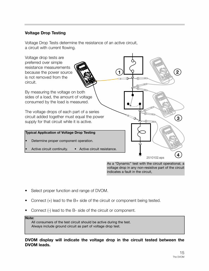
Voltage Drop Testing
Voltage Drop Tests determine the resistance of an active circuit, a circuit with current flowing.
Voltage drop tests are preferred over simple resistance measurementsbecause the power sourceis not removed from the circuit.
By measuring the voltage on bothsides of a load, the amount of voltageconsumed by the load is measured.
The voltage drops of each part of a seriescircuit added together must equal the power supply for that circuit while it is active.
• Select proper function and range of DVOM.
• Connect (+) lead to the B+ side of the circuit or component being tested.
• Connect (-) lead to the B- side of the circuit or component.
DVOM display will indicate the voltage drop in the circuit tested between theDVOM leads.
Typical Application of Voltage Drop Testing
• Determine proper component operation.
• Active circuit continuity. • Active circuit resistance.
As a “Dynamic” test with the circuit operational, avoltage drop in any non-resistive part of the circuitindicates a fault in the circuit,
Note:All consumers of the test circuit should be active during the test.Always include ground circuit as part of voltage drop test.
2510102.eps
16The DVOM
REC
YCLE
LEAD
RETURN
DA
NG
ER /
POIS
ON
SUFF
ICIE
NTL
Y C
HA
RG
ED
INSU
FFIC
IEN
TLY
CH
AR
GED
REP
LAC
E B
ATT
ERY
Pb
REC
YCLE
LEAD
RETURN
DA
NG
ER /
POIS
ON
SUFF
ICIE
NTL
Y C
HA
RG
ED
INSU
FFIC
IEN
TLY
CH
AR
GED
REP
LAC
E B
ATT
ERY
Pb
REC
YCLE
LEAD
RETURN
DA
NG
ER /
POIS
ON
SUFF
ICIE
NTL
Y C
HA
RG
ED
INSU
FFIC
IEN
TLY
CH
AR
GED
REP
LAC
E B
ATT
ERY
Pb
REC
YCLE
LEAD
RETURN
DA
NG
ER /
POIS
ON
SUFF
ICIE
NTL
Y C
HA
RG
ED
INSU
FFIC
IEN
TLY
CH
AR
GED
REP
LAC
E B
ATT
ERY
Pb
Label the Picture with the proper test name..
125101078.eps 12510179.eps
12510180.eps 12510181.eps
Worksheet
17The DVOM
PowerDistributionBox
F3
Hot All Times
Testing Circuits
Circuit 1
Build this circuit per Wiring diagram.Use one bulb initially, second bulb will be added.
Do not turn on power supply until instructed.
Before applying power check voltage of power supply.
12510183b.jpeg
125101206.eps
Completed circuit should look similar to this.
• Measure resistance of one bulb.
• Turn on power supply. Measure voltage dropacross entire circuit.
• Measure voltage drop across bulb.
• Measure amperage of the circuit.
• Measure the resistance across a second bulb.
• Install the second bulb.Measure amperage of the circuit.
• How did the amperage change?Why?
• Measure the voltage drop across eachbulb.
• Check voltage drop across top of fuse.(Third from right)
• Remove fuse and check voltage drop across fuse terminals.
• What type of circuit is this?
STOP DO NOT DISASSEMBLE CIRCUIT
18The DVOM
PowerDistributionBox
F3
Hot All Times
1 2
3 4
5 6
B1 B2
B3 B4
Circuit 2
Build this circuit using the Wiring diagram.
Be sure the power is OFF.
• What should the voltage be at points1 and 2 ?(Do not measure)
• What should the voltage be at points3 and 4 ?(Do not measure)
• Turn on the power supply. Measure voltageat 1. 2.
• Measure voltage drop B 1.
• Measure voltage drop across both bulbs ineach leg of circuit.
• Measure amperage in bulbs B1/B3.
• Estimate the total amperage of the circuit.
How was the answer calculated?
• Measure total circuit amperage.
• Remove bulb B4 from circuit.
• Measure amperage on circuit with only onebulb burning.
• What is the effect on the total circuit amperage.
• What type of circuit is this?
12510184b.jpeg
Completed circuit should look similar to this.
125101207.eps
19The DVOM
PowerDistributionBox
F3
Hot All Times
ResistorPack
2 3
Circuit 3
Remove all light bulbs and jumpers leavingthe power distribution box and switch.
Be sure power is off.
Build circuit per wiring diagram.
DO NOT APPLY POWER AT THIS TIME.
12510185a.jpeg
125101208.eps
• Measure resistance of each resistor at resistor.
• Measure resistance between Pin 3on Power Distribution Box (PDB)and Pin 2 on Resistor Pack (RP).
• Are the resistors wired in series or parallel?
• Turn on power, measure voltage at powersupply.Turn off power supply.
• Using Ohms’ law, calculate the amperage of the circuit at RP Pin 3. RP Pin 2.
• Turn on power supply and switch.Measure the amperage at RP Pin 3.RP Pin 2
• With B- applied at RP Pin3 what is the voltage drop at RP Pin 3 and PDB ?RP Pin 2 and PDB ?
• Move B- to RP Pin 2 and re-measure voltage drops.
• Turn off power supply.Why did the voltage drops differ?
Completed circuit should look similar to this.
Circuit 4
Build circuit per wiring diagram.
• With power off, Switch in down posi-tion measure resistance between Pin 2 and Com of slide switch.
Slide switch to up position, measure resistance between Pin 1and Com.
• Turn on power, put slide switch inup position.
• Measure supply voltage at PDB Pins 1/3.
• Measure voltage at Pin 86 of relay.
• Measure voltage drop between pins86/85 of relay.(Switch in down posi-tion)
• Check voltage drop between pins30/87 of relay.
• Push down button on push buttonswitch and hold. Recheck voltagedrops on relay pins 86/85.30/87.What happened to the voltage drops?
• Move red jumper from Pin 2 of slide switchto Pin 1 of slide switch. Put switch in up position. Measure amperage of circuit.
(Only two bulbs shouldbe burning.) Push button on switch.(All lights should burn) Measure amperage.
• Continue pushing button, check voltage drop Pin 86 of relay to B-What happened ?
20The DVOM
PowerDistributionBox
F1 F3
86
85
30
87
1 2
SlideSwitch
NO
NO
PBSwitch
125101209.eps
12510187.jpeg
Completed circuit should look similar to this.
21The DVOM
Worksheet
AUTO RANGE RECORD MAX MIN AVG AC DCH
0 1 2 3 44000mV
ms % m V AM K ΩHz RPM
MIN MAXZERO RANGE HOLD H
RPM % DUTY ALERT
SMOOTH HZ ms-PULSE TRIGGER+-
OFF
V
RPMV
mV Ω+
mA A
mA A
1000 V MAX
400mA MAX Fused
10A MAX FUSED
To Measure Red Lead Black Lead Rotary Switch
AC voltage
DC millivoltsDC voltageAC milliampsAC ampsDC milliampsDC AmpsOhmsDiode Test
NOTE: Some meters may have leads and functions in different locationsExplanation of more advanced features of your DVOM can be obtained in the Users Manual
Tip on Using a DVOM
Inspect test leads and replace dam-aged leads.
Do not use a meter if it looks dam-aged.
Select the proper range and functionfor your test.
Disconnect the live test lead beforedisconnecting the common lead.
When measuring current, turn thepower off in the circuit before connect-ing the meter.
Check meter fuse(s).
12510013a.eps
4321
22The DVOM
Worksheet
1. Vehicle Model:
Customer Complaint: Vehicle does not start.
Measure Battery Voltage at Jumper Terminal:
Measure Voltage at Battery:
Measure Voltage Drop on Battery Cable:
Correction:
2. Vehicle Model:
Customer Complaint: Rear window defogger does not work.
Measure voltage at fuse:
Measure voltage at term 30 of relay:
Ohm wire from fuse to relay:
Correction:
3.
Vehicle Model:
Measure amperage draw of rear washer pump:
Measure amperage draw of front washer pump:
4.
Vehicle Model:
Measure primary resistance of ignition coil:
What is the nominal value for the ignition coil:
23The DVOM
5.Vehicle Model:
Measure the amperage draw of the fuel pump:
Where is the best place to make this measurement:
What is the nominal value of this measurement:
6.Vehicle Model:
Measure the voltage drop across the workside of the fuel pump relay with the pump notrunning:
Measure the voltage drop across the relay with the pump running:
7.Vehicle Model:
Measure continuity of wire from DME to Injector #1:
Measure the resistance of this wire:
8.Vehicle Model:
Measure voltage drop on B+ cable to starter:
Measure voltage drop on B- cable at Battery:
Measure amperage draw on starter:
Questions:
24The DVOM
Review Questions
1. What are the four main factors that determine accuracy of electrical measurements?
2. What is the importance of impedance in a multimeter?
3. What does a meter reading of OL indicate during Ohms measurement?
4. What is the correct procedure for measuring amps and does this differ from other measurements ?
5. Why should test lights be avoided?
6. What happens if the leads are reversed while measuring Ohms of a circuit which includes a diode?
7. Why are voltage drop tests preferred over ohms tests?
8. How many amps are indicated by a meter reading of 238mA ?
9. What does a voltage drop reading of 12.6v across relay terminals 86 and 85 indicate?
What would the expected the voltage drop be across 30 and 87 at the same time ?
10. When measuring voltage, how is a meter connected to the circuit?
11. Where will the red lead be installed in the meter when measuring mA?When measuring amps?
12. What would a voltage drop of 12.6v across a fuse indicate?