111


Table of Contents
efio!121A BOM………………………………………………………………. 1
efio!121A Sub. Assembly S.O.P…………………………….………………... 9
efio!121A 12.1" LCD Instruction manual…………………………………….. 24
efio!121A System Setup Instruction manual………………………………….. 34
efio!121A (Complete set) Instruction Manual………………………………... 55
efio!121A (CARRYING BAG) Packaging Instruction Manual………………. 67
efio!121A 2-IN-1 Packing S.O.P……………………………………………... 73
efio!121A Disassembly……………………………………………………….. 82

efio!121A Notebook BOM(Internal code: D212A)========== =============== ===============================================LEVELS ITEM NUMBER DESCRIPTION QTY
123456789 M-D212A D212A ID2 MODEL========== =============== ===============================================PCBA.....5 82-873030-00 D212A-PCB ASS'Y-VI-K7-REV:0-W/WI 1....4 80-690000-00D P22AJ-PCB ASS'Y-VI-USB-REV:D 1
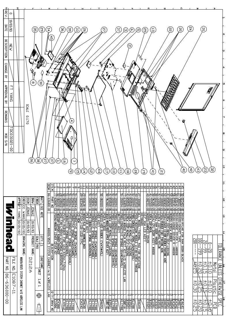
SYSTEM CABINET.....5 27-300051-20 N222S1-GASKET TAPE-D4877A 1.....5 27-330000-00 ALL MODEL-THERMAL PAD FOR HEATSI 1.....5 28-200022-11 2nd FAN-L=80mm-W/SPONGE 1.....5 29-001638-02 N222S1-RJ11 JACK HARNESS-SH638B 1.....5 29-015340-00 P22AJ-SB-USB FPC-CA3400 1.....5 40-002311-00 N222S1-HARNESS COVER-C33210 1.....5 40-003510-11 P22AJ-HEATSINK MODULE W/FAN-SCRE 1.....5 41-721520-03 SCREW ISOT-M2X3L-SELF-LOCKING ¡í 4.....5 41-721526-05 SCREW ISOT-M2.6X5L H=0.8mm-NYLOK 2.....5 41-850520-06 SCREW ISOP-M2X6L-SELF-LOCKING-B3 17.....5 50-022150-70 P22AJ-RAM DOOR-#8028-C3323E 1.....5 50-023421-00 D212A-MYLAR FOR RAM DOOR-BLACK-I 1.....5 50-035141-30 D212A-HINGE COVER R-#8028-E4343D 1.....5 50-035142-30 D212A-HINGE COVER L-#8028-E4342E 1.....5 50-963001-20 P22AJ-CPU DOOR ASS'Y-#8028-E1081 1.....5 50-963601-00 D212A-UPPER COVER ASS'Y-#8028/85 1.....5 51-350094-01 CONDUCTIVE SPONGE 5X2X1000mm-KL1 0.03.....5 51-350094-02 CONDUCTIVE SPONGE 5X3.5X1000mm-K 0.08.....5 51-350094-03 CONDUCTIVE SPONGE 5X5.5X1000mm-K 0.08.....5 51-350094-10 CONDUCTIVE SPONGE 5X0.5X1000mm-K 0.085.....5 51-350094-15 P88S-CONDUCTIVE SPONGE 10X0.5X10 0.215.....5 51-350094-16 P93S-CONDUCTIOVE SPONGE 10X2X100 0.03

efio!121A Notebook BOM(Internal code: D212A)========== =============== ===============================================LEVELS ITEM NUMBER DESCRIPTION QTY
123456789 M-D212A D212A ID2 MODEL========== =============== ===============================================.....5 51-350100-00 P88TEM-SPONGE 5X1X1000mm 0.02.....5 52-000000-20 P22AJ-RUBBER FOOT-PANTONE 428C-D 2.....5 52-002020-00 N222S1-HDD RUBBER-D46930 1.....5 52-002021-00 N222S1-SCREW RUBBER-D48290 2.....5 52-002022-20 P22AJ-LOWER CD-ROM RUBBER-PANTON 1.....5 52-002030-00 N222S8P-SUPPORT RUBBER-20X20X5.5 1.....5 52-002080-00 P22AJ-RUBBER FOR USB-4X2mm,T=2mm 1
LOWER COVER KIT......6 40-002420-04 P22AU-LOWER COVER #8028M-B1277D 1......6 40-006040-00 N222S1-BATTERY HOOK-B3377A 1......6 40-011951-00 N222S1-BATTERY LATCH SPRING-D479 1......6 41-420520-03 SCREW BPS/W (¡í5.5)-M2X3L-NYLOK- 2......6 41-690022-48 WASHER-OD=4.8 IO=2.2 T=0.5-D4883 2......6 50-023310-00 N222S8L-MYLAR-10X4X0.2T-E43290-S 1......6 50-023335-00 P22AJ-MYLAR FOR RJ11 LEFT SIDE-t 1......6 50-043000-30 P22AJ-BATTERY LATCH-#8028-D4540E 1......6 51-036041-00 N222S1-HDD SPONGE FOR LOWER UP S 1......6 51-036042-00 N222S1-HDD SPONGE FOR LOWER DOWN 1......6 52-000000-20 P22AJ-RUBBER FOOT-PANTONE 428C-D 2
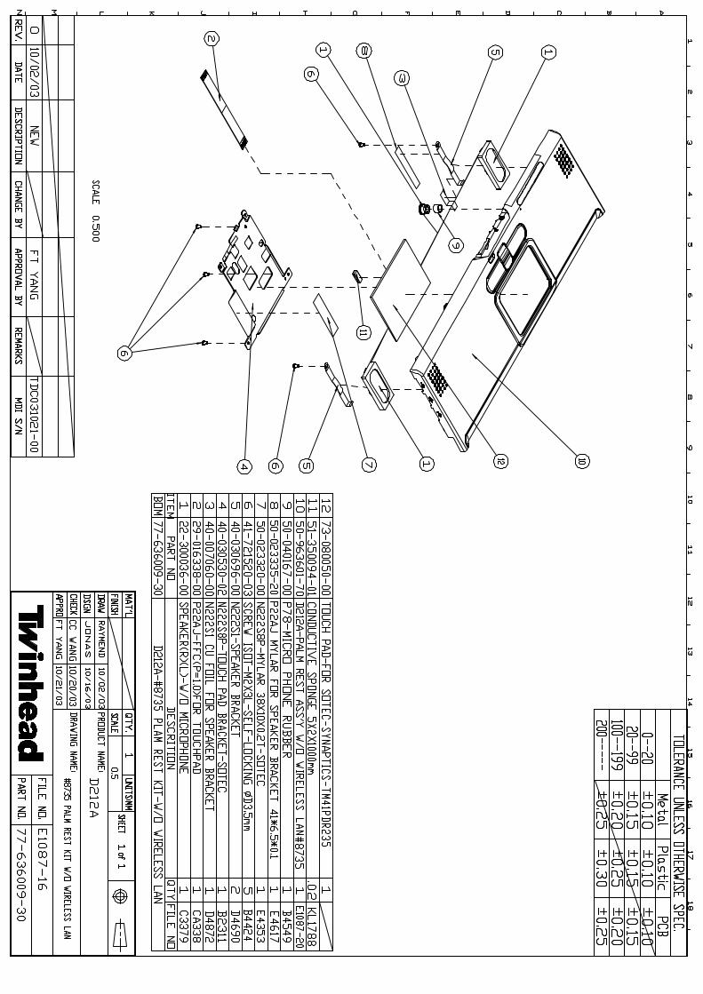
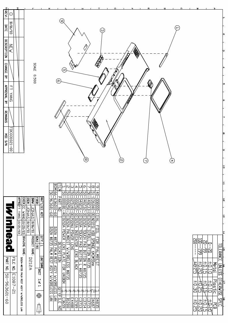
PALM REST KIT......6 22-300036-00 SPK (R)(L) W/MICROPHONE-C33790-S 1......6 29-016338-00 P22AJ-FFC (P=1.0) FOR TOUCHPAD-C 1......6 40-007060-00 N222S1-CU-FOIL FOR SPEAKER BRACK 1......6 40-030530-02 N222S8P-TOUCH PAD BRACKET-B2311C 1......6 40-030696-00 N222S1-SPEAKER BRACKET-D46900 2

efio!121A Notebook BOM(Internal code: D212A)========== =============== ===============================================LEVELS ITEM NUMBER DESCRIPTION QTY
123456789 M-D212A D212A ID2 MODEL========== =============== ===============================================......6 41-721520-03 SCREW ISOT-M2X3L-SELF-LOCKING ¡í 5......6 50-023320-00 N222S8P-MYLAR 38X10X0.2T-E43530- 1......6 50-023335-20 P22AJ-MYLAR FOR SPEAKER BRACKET- 1......6 50-040167-00 P78-MICRO PHONE RUBBER-B4549A 1......6 50-963601-10 D212A-PALM REST ASS'Y #8028-W/O WLAN 1......6 50-963601-20 D212A-PALM REST ASS'Y W/WLAN-#8027 1......6 51-350094-01 CONDUCTIVE SPONGE 5X2X1000mm-KL1 0.02......6 73-080052-00 TOUCH PAD-FOR SOTEC-SYNAPTICS-TM 1
UPPER COVER KIT-W/Z ANTENNA......6 22-600060-11 PIFA ANTENNA-C3530A-P22T 1......6 27-300021-00 A2121-DOUBLE ADHESIVE (R)-WX4mm 1......6 50-963601-00 D212A-UPPER COVER ASS'Y-#8028/85 1
24X CDROM ASS'Y FOR TEAC....4 50-963001-70 P22AJ-#8028 TEAC CD-ROM BEZEL AS 1
24X PANASONIC COMBO ASS'Y #8028....4 50-963001-10 P22AJ-PANASONIC COMBO BEZEL ASS' 1
24X PANASONIC COMBO ASS'Y #8735....4 50-963601-D0 D212A-PANASONIC COMBO BEZEL ASS' 1
8X DVD-ROM ASS'Y-FOR QSI.....5 50-963401-40 P22T-QUANTA DVD-ROM BEZEL ASS'Y- 1
HDD KIT

efio!121A Notebook BOM(Internal code: D212A)========== =============== ===============================================LEVELS ITEM NUMBER DESCRIPTION QTY
123456789 M-D212A D212A ID2 MODEL========== =============== ===============================================...3 40-008140-00 D212A-AL FOIL FOR HDD BRACKET-E4 2...3 60-010001-00 PE BAG 70X120mm 1....4 40-030691-00 N222S1-HDD BRACKET-C3421B 1....4 41-870130-04 SCREW ISOF-M3X4L-B3519K 4
US KB...3 71-700185-01 K/B-85 KEY-US-N222S8-JME 1
KR KB...3 71-710104-00 K/B-85 KEY-KR-N222S8PII-NEW MICR 1
SWISS KB...3 71-710106-00 K/B-85 KEY-SW-36599#-N222S8PII-N 1
GR KB...3 71-710107-00 K/B-85 KEY-GR-GRAY-N222S8SA-JME- 1
FR KB...3 71-710105-00 K/B-85 KEY-FR-N222S8SA-JME-FOR S 1
UK KB...3 71-710108-00 K/B-85 KEY-UK-N222S8SA-JME-FOR S 1
TW KB...3 71-710102-00 K/B-85 KEY-TW-N222S8SA-JME-FOR S 1
TL KB

efio!121A Notebook BOM(Internal code: D212A)========== =============== ===============================================LEVELS ITEM NUMBER DESCRIPTION QTY
123456789 M-D212A D212A ID2 MODEL========== =============== ===============================================...3 71-710128-00 K/B-85 KEY-TL-N222S8L/P-JME-FOR 1
RU KB...3 71-810124-00 K/B-85KEYS-RU-#36599-D212A-W/NEW 1
JP KB...3 71-700185-17 K/B-85 KEY-JP-N222S8-JME 1
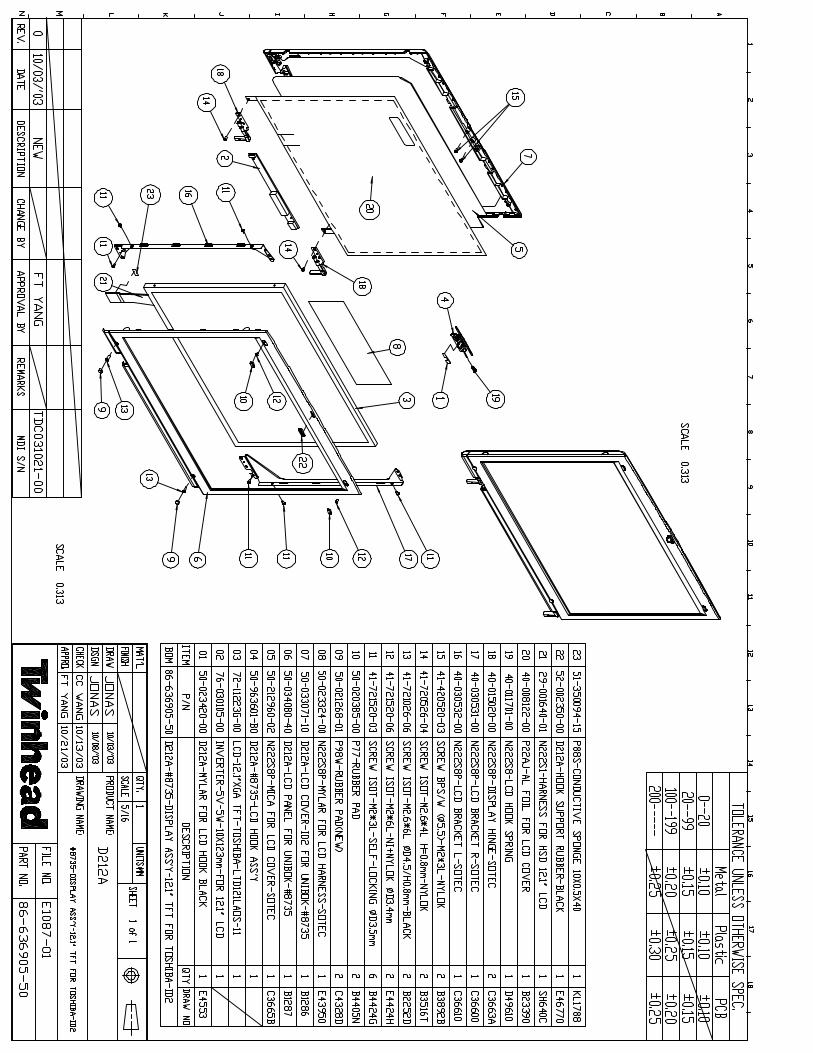
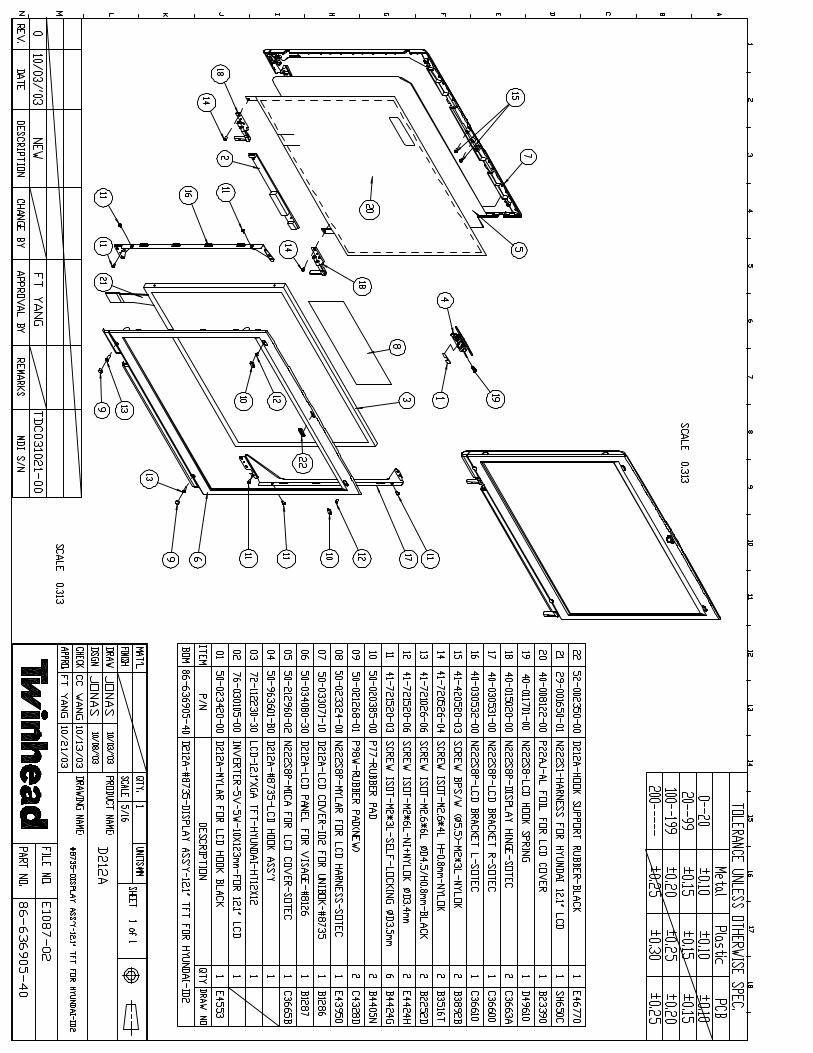
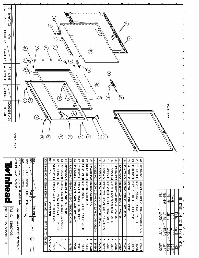
DISPLAY ASS'Y...3 29-001640-01 N222S1-HARNESS FOR HSD 12.1" LCD 1...3 40-008122-00 P22AJ-AL FOIL FOR LCD COVER-B233 1...3 40-011701-00 N222S8-LCD HOOK SPRING-D49610 1...3 40-015020-00 N222S8P-DISPLAY HINGE-C3663A-SOT 2...3 40-030531-00 N222S8P-LCD BRACKET R-C36600-SOT 1...3 40-030532-00 N222S8P-LCD BRACKET L-C36610-SOT 1...3 41-420520-03 SCREW BPS/W (¡í5.5)-M2X3L-NYLOK- 2...3 41-720526-04 SCREW ISOT-M2.6X4L H=0.8mm-NYLOK 2...3 41-721026-06 SCREW ISOT-M2.6X6L ¡íD4.5/H0.8mm 2...3 41-721520-03 SCREW ISOT-M2X3L-SELF-LOCKING ¡í 6...3 41-721520-06 SCREW ISOT-M2X6L-NI+NYLOK #1 I 2...3 50-020385-20 N222S8L-RUBBER PAD-B4405N-SOTEC 1...3 50-021268-20 N222S8L-RUBBER PAD-C4328D-SOTEC 1...3 50-023324-00 N222S8P-MYLAR FOR LCD HARNESS-E4 1...3 50-023420-00 D212A-MYLAR FOR LCD HOOK-BLACK-E 1...3 50-033071-00 D212A-LCD COVER ID2-#8027-B12860 1...3 50-212960-02 N222S8P-MICA FOR LCD COVER-C3665 1...3 50-963601-C0 D212A-LCD HOOK ASS'Y-#8801 1

efio!121A Notebook BOM(Internal code: D212A)========== =============== ===============================================LEVELS ITEM NUMBER DESCRIPTION QTY
123456789 M-D212A D212A ID2 MODEL========== =============== ===============================================...3 52-002350-10 D212A-HOOK SUPPORT RUBBER-PANTON 1...3 76-030105-00 INVERTER-5V-5W-10X123mm-FOR 12.1 1
5 IN 1 PACKING FOR US...3 60-010026-00 PE BAG 200X150 mm A4382 1...3 60-010200-00 BIG PE BAG 0.017...3 60-012001-00 PE BAG W/ARTWORK 360*380 1...3 60-012002-00 ANTI-STATIC BAG 110*290 1...3 61-000845-00 PET OPC 1206 STRAC 0...3 61-007051-00 N222S1-5IN1 PAPER CUSHION FOR BA 0.2...3 61-012184-00 N222S1-5IN1 PAPER BOARD FOR BATT 0.2...3 61-012193-00 N222S1-5 IN 1 PAPER TUBE-D48980 0.4...3 61-015060-00 N222S1-PROTECT PAPER FOR K/B-D48 1...3 61-050083-10 N222S1-5IN1 CARTON-A4873B 0.2...3 61-960601-A0 N222S1-5IN1 LOWER PAPER CUSHION 0.2...3 61-960601-B0 N222S1-5IN1 UPPER PAPER CUSHION 0.2...3 63-001132-00 PACKING LABEL 100X150mm-C4219A 0.2
GENERIC 2 IN 1 PACKING...3 29-130244-00 P93SE-MODEM CABLE-CA244 1...3 60-010001-00 PE BAG 70X120mm 1...3 60-010070-00 PLASTIC BAG-35cmX25cm-FOR CD/MAN 1...3 62-030273-00 USER'S MANUAL-DE/EN-R:00-D212A 1...3 70-140629-01 UTILITY CD-R1.01-D212A 1...3 76-010562-00 ADAPTER-20V-60W-LSE9802A2060-SLS 1....4 50-020002-00 PLASTIC HANDLE-A3280 1....4 60-005040-00 R14SE-CARRY BAG FOR GENERIC 1

efio!121A Notebook BOM(Internal code: D212A)========== =============== ===============================================LEVELS ITEM NUMBER DESCRIPTION QTY
123456789 M-D212A D212A ID2 MODEL========== =============== ===============================================....4 60-010003-00 PE BAG 220X280mm 1....4 60-010026-00 PE BAG 200X150 mm A4382 1....4 60-010067-00 PE-BAG-400X300mm-B4752A-P79S-PE 1....4 60-010200-00 BIG PE BAG 0.041....4 61-007050-00 N222S1-PAPER CUSHION-C34160-FOR 1....4 61-012180-00 N222S1-PAPER TUBE-C3418A-FOR BAT 1....4 61-012195-00 N222S1-PAPER SHEET-C34610-FOR MO 1....4 61-015061-00 N222S1-PROTECT PAPER FOR SYSTEM- 1....4 61-040064-40 A2010-COLOR BOX W/CARRY BAG-A245 1....4 61-050094-01 P88TE-CARTON FOR W/CARRY BAG-A24 0.5....4 61-960601-80 N222S1-2IN1 L PAPER CUSHION ASS' 1....4 61-960601-90 N222S1-2IN1 R PAPER CUSHION ASS' 1
PARTS KIT FOR GERERIC-W/O LOGO ...3 50-023425-00 D212A PROTECTIVE MYLAR FOR LCD C 1...3 50-034080-00 D212A-LCD PANEL W/O LOGO-#8126-B 1...3 63-040100-Q0 D212A-FCC LABEL SYSTEM-C3435-FOR 1
PARTS KIT FOR T/H ...3 40-006120-00 D212A-LCD FRONT PLATE ID2-FOR TW 1...3 50-034080-10 D212A-LCD PANEL FOR TH-#8126-B12 1...3 63-040102-R5 D212A-MODEL NAME EFIO! 122A LABE 1
56K MODEM ASS'Y...3 41-721520-03 SCREW ISOT-M2X3L-SELF-LOCKING ¡í 2...3 63-250190-00 KEY PARTS BARCODE LABEL-KL18260 1...3 76-060007-00 MDC MODEM CARD-SMART LINK-MDC56S 1

efio!121A Notebook BOM(Internal code: D212A)========== =============== ===============================================LEVELS ITEM NUMBER DESCRIPTION QTY
123456789 M-D212A D212A ID2 MODEL========== =============== ===============================================
POWER CORD FOR JP (2-PIN)..2 29-020151-10 P10-POWER CORD-JP 2P-BLACK-SP-12 1
POWER CORD FOR US, TW, Phillippine, Korea, Canada..2 29-020181-10 N222S1-POWER CORD FOR US/PL/C-SP 1
POWER CORD FOR German, French, Holland, Austrian, Swedish, Norwegian, Belgium..2 29-020183-11 ALL MODEL-POWER CORD FOR GR/FR/H 1
POWER CORD FOR KR..2 29-020183-20 ALL MODEL-POWER CORD FOR KR-SP-0 1
POWER CORD FOR England, Singapore, Hong Kong..2 29-020185-20 9000,5000,2000,1000,N222S1-POWER 1
POWER CORD FOR ML..2 29-020186-10 N222S1,N222S8-POWER CORD FOR CHI 1
WIRELESS...3 52-003091-00 P22T-RUBBER FOR WIRELESS-E45500 2...3 76-070005-00 WLAN MODULE MINI USB W/HARNESS-T 1

Tw inhead International Corp.
REVISION: 0
PREPARED BY CONCURREDBY APPROVED BY
NEW RELEASE PE: NA
DOCUMENT CODE:TESOP261
RELEASE DATE:
PAGE: 14 (total 14 pages)
DESCRIPTION
efio!121A Sub Ass'y S.O.P.

Page/Version
Page Version Page Version Page Version Page Version1. Instruction manual P.01 1 0
P.2~P.14 2 03 0
1.6501 Upper Cover Assembly (2 people) P.02~P.03 4 02.6502 LOWER COVER Assembly (3 people) P.04 ~ P.06 5 03.6504 CD-ROM Assembly (2 people) P.07~ P.08 6 04.6506 HDD Assembly (1 people) P.09 7 05.6551 PalM REST Assembly (5 people) P.10~ P.14 8 0
9 010 011 012 013 014 0
BOM calls for real fabric; the numbers in the S.O.P are for reference only
PAGE:01
(Document NO.):TESOP261
REV: 0
This manual is for efio!121A model System setup
Name of S.O.P: efio!121A SUB ASSEMBLY SOP
2.Fabricated material setup instruction (19 peoplerequired)
Twinhead International Corp.

Working name: 6501-1 Revision: 0 Date: 2003.09.01 (Manufacturing Section): PE
Difference Operating Item Part name/specification Part/number Q'TY Operation description Important note Jig/fixture
3 CONDUCTIVESPONGE(10X0.5X45mm) 51-350094-15 1 Attach two conductive sponges as shown
in diagramDo not allow sponge to cross red
line NA
4 CONDUCTIVESPONGE(10X0.5X35mm) 51-350094-15 1 Attach two conductive sponges as shown
in diagram NA NA
5 CONDUCTIVESPONGE(10X2X20mm) 51-350094-16 1 Attach two conductive sponges as shown
in diagram NA NA
( Twinhead S.O.P ) ( Document NO): TESOP261Name of S.O.P: efio!121A UPPER COVER SOP
Explanation of illustration
1 efio!121A-UPPER COVER ASS'Y 50-963601-00 1Check UPPER COVER to make sure it isnot damaged or distorted; clean withalcohol
Check the appearance
PAGE: 02
NA
2 CONDUCTIVESPONGE(10X0.5X45mm) 51-350094-15 2 Attach two conductive sponges as shown
in diagramDo not allow sponge to cross red
line NA
Tw inhead International Corp.
3
1
2
When attaching this sponge,align with red lines
8mm
5
35mm
13m
m
27mm

Working name: 6501-2 Revision: 0 Date: 2003.09.01 (Manufacturing Section): PE
Difference Operating Item Part name/specification Part/number Q'TY Operation description Important note Jig/fixture
1 DOUBLEADHESIVE(R)(25X4X0.15mm) 27-300021-00 1 Attach DOUBLE ADHESIVE on upper cover part; do
not allow tape to extend over edgeDo allow tape to extend over
edge NA
2 PIFA ANTENNA-C3530A-P22T H 1Place antenna on upper cover as shown in diagram;make sure antenna and upper cover are tightlyconnected
N/A NA
3 TAPE (NARROW)(5~6cm) 61-080022-00 1 Use black tape to fix the antenna as shown in diagram N/A N/A
4 403 quick-drying glue NA 1 Glue antenna magnet hook to upper cover's fillister N/A NA
PAGE: 03
Implementthese steps
while wirelesslan function on
( Twinhead S.O.P ) ( Document NO): TESOP261Name of S.O.P: efio!121A upper cover SOP
Explanation of illustration
3
4
2
1DOUBLEADHESIVE 25 mm
Tw inhead International Corp.

Revision: 0 Date: 2003.09.01 (Manufacturing Section): PE
Difference Operating Item Part name/specification Part/number Q'TY Operation description Important note Jig/fixture
1 P22AU-LOWER COVER 40-002420-04 1 Check appearance for scratches or damage. NA NA
2 N222S1-BATTERY LATCHSPRING 40-011951-00 1 Note the direction of the spring
3 N222S1-BATTERY HOOK 40-006040-00 1 NA
4 WASHER-OD=4.8 IO=2.2 T=0.5-D48830 41-690022-48 2 Put screw WASHER on base and align with lockhole NA NA
5 SCREW BPS/W-M2X3L-NYLOK 41-420520-03 2 Tighten on hook in a.b. order NA Electrical screwdriver/Torque: 1.5±0.5Kgf-cm
PAGE: 04
Explanation of illustration
( Twinhead S.O.P ) ( Document NO): TESOP261Name of S.O.P: efio!121A lower cover SOP Working name: 6502-1
Hook the spring from the rear and assemble onto base.Installing outer side of spring hook onto base first asshown in diagram.
NA
2
5
31
4
Tw inhead International Corp.

Revision: 0 Date: 2003.09.01 (Manufacturing Section): PE
Difference Operating Item Part name/specification Part/number Q'TY Operation description Important note Jig/fixture
1 N222S1-HDD SPONGE FOR LOWERUP SIDE 51-036041-00 1 Attach as shown in diagram N/A Mylar
2 N222S1-HDD SPONGE FOR LOWERDOWN SIDE 51-036042-00 1 Attach as shown in diagram NA NA
3 CONDUCTIVE SPONGE (5x3.5x80mm) 51-350094-02 1 Attach as shown in diagram (50mm) NA NA
4 CONDUCTIVE SPONGE (5x5.5x80mm) 51-350094-03 1 Attach as shown in diagram (50mm) NA NA
5 N222S8L-MYLAR-10X4X0.2T-SOTEC 50-023310-00 1 Attach black MYLAR on bottom cover as shown indiagram NA
NA
6 P22AJ-MYLAR FOR RJ11 LEFT SIDEt:0.2 (7X2X0.2tmm) 50-023335-00 1 At RJ11, add Mylar on bottom cover as shown in
diagram NA NA
Explanation of illustration
PAGE: 05
( Twinhead S.O.P ) ( Document NO): TESOP261Name of S.O.P: efio!121A lower cover SOP Working name: 6502-2
38mm
1
43
2
56
Follow the edge of the line toattach the Mylar. Be carefulto stick in the exact positionindicated.
Tw inhead International Corp.

Revision: 0 Date: 2003.09.01 (Manufacturing Section): PE
Difference Operating Item Part name/specification Part/number Q'TY Operation description Important note Jig/fixture
1 P22AJ-BATTERY LATCH 50-043000-30 1 Install BATTERY LATCH Note the direction: arrowpoints right NA
2 P22AJ-RUBBER FOOT 52-000000-20 2 Attach rubber foot N/A NA
3 NA NA 1 Place bottom cover in a protective bag NA NA
Explanation of illustration
PAGE: 06
( Twinhead S.O.P ) ( Document NO): TESOP261Name of S.O.P: efio!121A lower cover SOP Working name: 6502-3
Must movesmoothly1
Attach tightly
Attach tightly2
Tw inhead International Corp.
Revision: 0 Date: 2003.09.01 (Manufacturing Section): PE
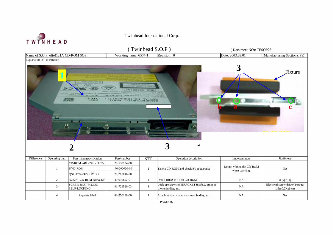
Difference Operating Item Part name/specification Part/number Q'TY Operation description Important note Jig/fixtureCD-ROM 24X 224E -TECA 70-130124-00
DVD-ROM 70-200030-00
QSI SBW-242 COMBO 70-210016-00
2 N222S1-CD-ROM BRACKET 40-030692-01 1 Install BRACKET on CD-ROM NA U type jag
3 SCREW ISOT-M2X3L-SELF-LOCKING 41-721520-03 3 Lock up screws on BRACKET in a.b.c. order as
shown in diagram. NA Electrical screw driver/Torque:1.5± 0.5Kgf-cm
4 keyparts label 63-250190-00 1 Attach keyparts label as shown in diagram. NA NA
PAGE: 07
Take a CD-ROM and check it's appearance Do not vibrate the CD-ROMwhen carrying.1 1 NA
Name of S.O.P: efio!121A CD-ROM SOP Working name: 6504-1 ( Twinhead S.O.P ) ( Document NO): TESOP261
Explanation of illustration
1
2
ab c
Fixture3
3
Tw inhead International Corp.

Revision: 0 Date: 2003.09.01 (Manufacturing Section): PE
Difference Operating Item Part name/specification Part/number Q'TY Operation description Important note Jig/fixture1 NA NA NA Take CD-ROM and eject disc tray
CD-ROM BEZEL 50-962801-XX
DVD BEZEL 50-963401-xx
CD-RW BEZEL 50-962801-XX
3 SCREW BTB 1.7*3L BLACK 41-650217-03 1 Lock up screws on BEZEL as shown in diagram. Eject tray 30 mm; place it on a tablesurface
Screwdriver /Torque: 0.8±0.2Kgf-cm
CD-RW 4 SCREW BTB 1.7*3L BLACK 41-650217-03 2 Tighten screws in order of a.b. (When screwing CD-RW's bezel , at (3)﹑(4) total of 3 screws.
NA Electrical screwdriver/Torque:0.8± 0.2Kgf-cm
Quanta DVD 5 TAPE (NARROW)-1cm 61-080022-00 1 When using Quanta DVD-ROM, attach a tape at theBEZEL right side hook and then assemble.
Tape is required when using aQuanta DVD N/A
1 Install BEZEL on CD-ROM tray base.
( Twinhead S.O.P ) ( Document NO): TESOP261
Explanation of illustration
PAGE: 08
Name of S.O.P: efio!121A CD-ROM SOP Working name: 6504-2
Check that bezel serial number iscorrect; Bezel must conform with
CD-ROM. Do not let BEZEL changeshape
NA2
2 3
1
Poke from here4
a
b
Tw inhead International Corp.
Revision: 0 Date: 2003.09.01 (Manufacturing Section): PE
Difference Operating Item Part name/specification Part/number Q'TY Operation description Important note Jig/fixture
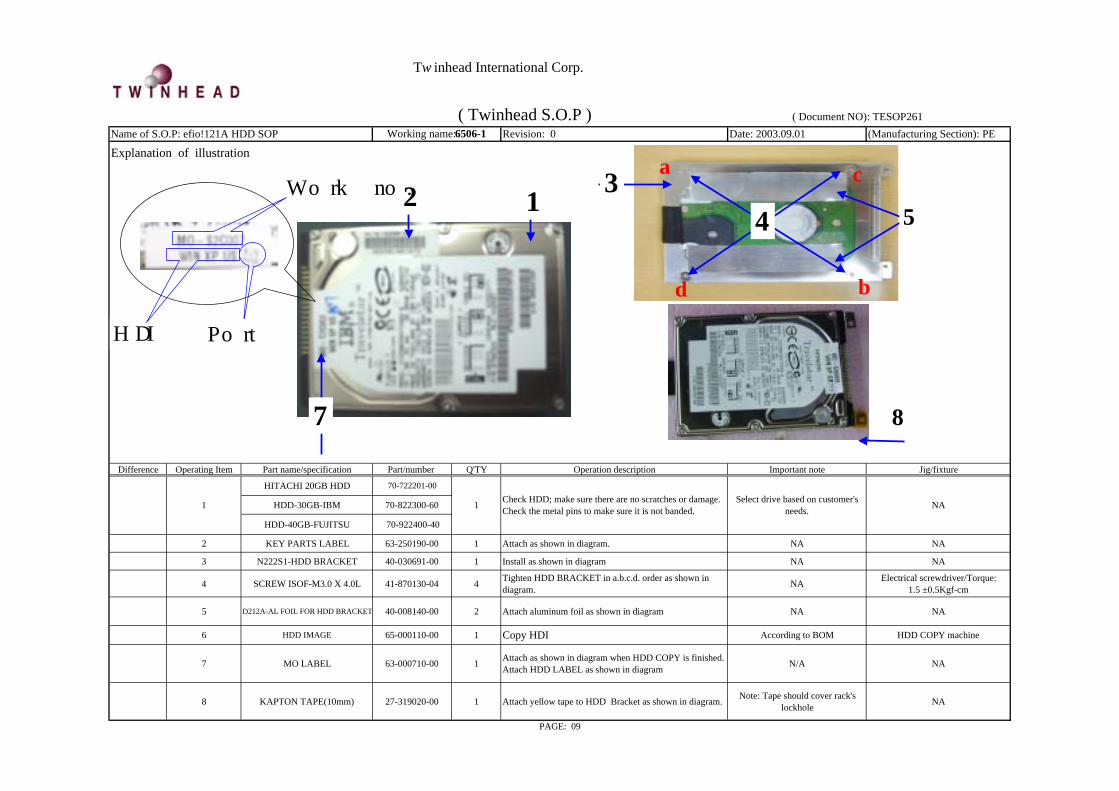
HITACHI 20GB HDD 70-722201-00
HDD-30GB-IBM 70-822300-60
HDD-40GB-FUJITSU 70-922400-40
2 KEY PARTS LABEL 63-250190-00 1 Attach as shown in diagram. NA NA
3 N222S1-HDD BRACKET 40-030691-00 1 Install as shown in diagram NA NA
4 SCREW ISOF-M3.0 X 4.0L 41-870130-04 4 Tighten HDD BRACKET in a.b.c.d. order as shown indiagram. NA Electrical screwdriver/Torque:
1.5 ±0.5Kgf-cm
5 D212A-AL FOIL FOR HDD BRACKET 40-008140-00 2 Attach aluminum foil as shown in diagram NA NA
6 HDD IMAGE 65-000110-00 1 Copy HDI According to BOM HDD COPY machine
7 MO LABEL 63-000710-00 1 Attach as shown in diagram when HDD COPY is finished.Attach HDD LABEL as shown in diagram N/A NA
8 KAPTON TAPE(10mm) 27-319020-00 1 Attach yellow tape to HDD Bracket as shown in diagram. Note: Tape should cover rack'slockhole NA
PAGE: 09
1 1 Check HDD; make sure there are no scratches or damage.Check the metal pins to make sure it is not banded.
Select drive based on customer'sneeds. NA
Name of S.O.P: efio!121A HDD SOP Working name:6506-1
Explanation of illustration
( Twinhead S.O.P ) ( Document NO): TESOP261
14
2Work no.
HDI Port
7 8
3 a
b
c
d
4 5
Tw inhead International Corp.
Revision: 0 Date: 2003.09.01 (Manufacturing Section): PE
Difference Operating Item Part name/specification Part/number Q'TY Operation description Important note Jig/fixture
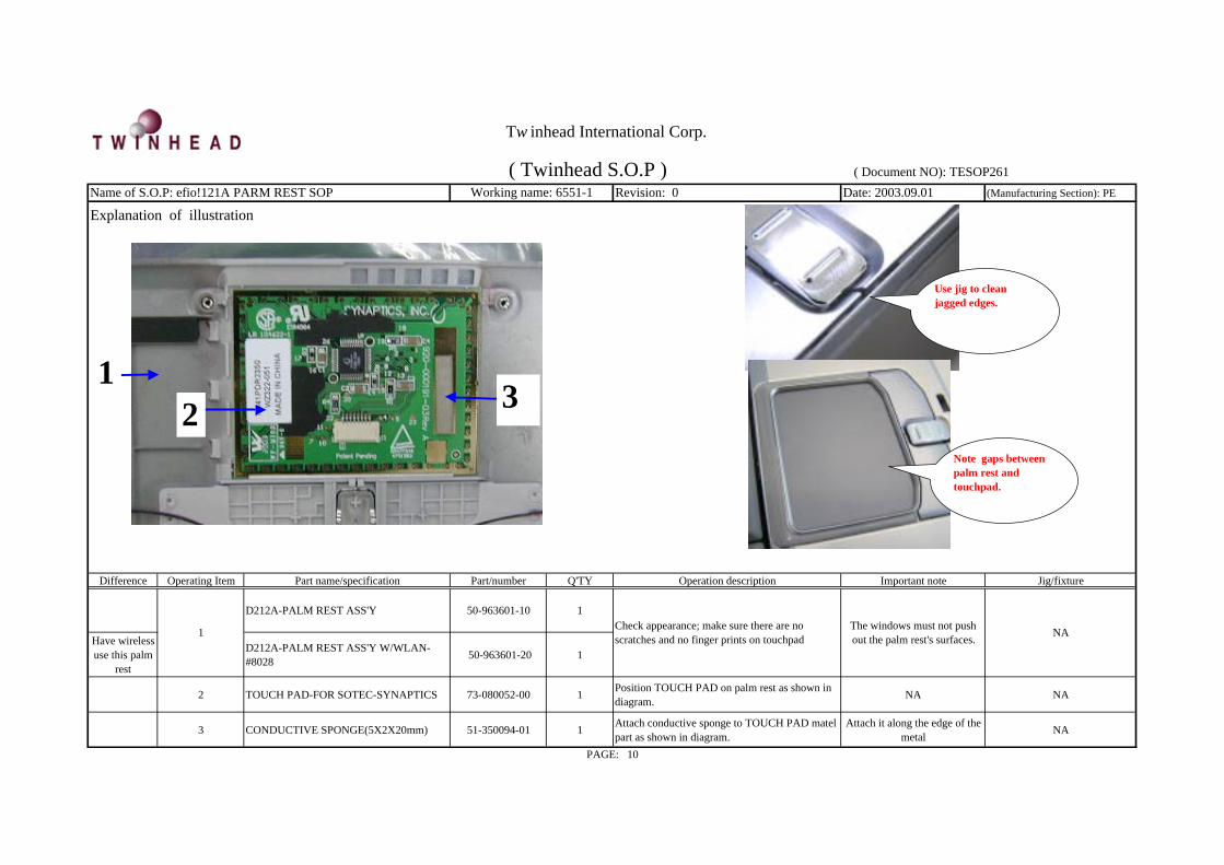
D212A-PALM REST ASS'Y 50-963601-10 1
Have wirelessuse this palm
rest
D212A-PALM REST ASS'Y W/WLAN-#8028 50-963601-20 1
2 TOUCH PAD-FOR SOTEC-SYNAPTICS 73-080052-00 1 Position TOUCH PAD on palm rest as shown indiagram. NA NA
3 CONDUCTIVE SPONGE(5X2X20mm) 51-350094-01 1 Attach conductive sponge to TOUCH PAD matelpart as shown in diagram.
Attach it along the edge of themetal NA
Check appearance; make sure there are noscratches and no finger prints on touchpad
The windows must not pushout the palm rest's surfaces. NA
PAGE: 10
1
( Twinhead S.O.P ) ( Document NO): TESOP261
Explanation of illustrationName of S.O.P: efio!121A PARM REST SOP Working name: 6551-1
132
Use jig to cleanjagged edges.
Note gaps betweenpalm rest andtouchpad.
Tw inhead International Corp.
Revision: 0 Date: 2003.09.01 (Manufacturing Section): PE
Explanation of illustration
Difference Operating Item Part name/specification Part/number Q'TY Operation description Important note Jig/fixture
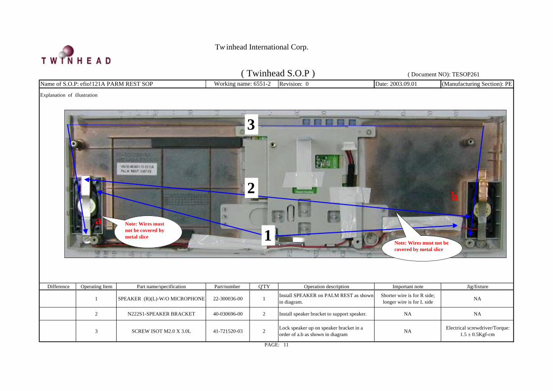
1 SPEAKER (R)(L)-W/O MICROPHONE 22-300036-00 1 Install SPEAKER on PALM REST as shownin diagram.
Shorter wire is for R side;longer wire is for L side NA
2 N222S1-SPEAKER BRACKET 40-030696-00 2 Install speaker bracket to support speaker. NA NA
3 SCREW ISOT M2.0 X 3.0L 41-721520-03 2 Lock speaker up on speaker bracket in aorder of a.b as shown in diagram NA Electrical screwdriver/Torque:
1.5 ± 0.5Kgf-cm
PAGE: 11
( Twinhead S.O.P ) ( Document NO): TESOP261Name of S.O.P: efio!121A PARM REST SOP Working name: 6551-2
2
a
b
Note: Wires mustnot be covered bymetal slice 1
Note: Wires must not becovered by metal slice
3
Tw inhead International Corp.

Working name: 6551-3 Revision: 0 Date: 2003.09.01 (Manufacturing Section): PEExplanation of illustration
Difference Operating Item Part name/specification Part/number Q'TY Operation description Important note Jig/fixture1 rubber for microphone 50-040617-00 1 Install rubber on microphone and install it at palm rest NA NA
2 NA NA 1 Arrange SPEAKER wires Arrange wires in position pillar NA
3 TAPE (NARROW)-1cm 61-080022-00 1 Attach tape to wires to fix as shown in diagram. NA NA
4 N222S1 CU-FOIL FOR SPEAKERBRACKET 40-007060-00 1 Attach copper foil to right side of PALM REST as
shown in diagram NA NA
PAGE: 12
( Twinhead S.O.P ) ( Document NO): TESOP261Name of S.O.P: efio!121A PARM REST SOP
arrange wires infillister
4
3
2
arrange wires infillister
Make the wirestighten and stick it
wires abovemetal slice
wires insidehook
wires abovemetal slice
1
Tw inhead International Corp.

Revision: 0 Date: 2003.09.01 (Manufacturing Section): PE
Difference Operating Item Part name/specification Part/number Q'TY Operation description Important note Jig/fixture
1 N222S8P-TOUCH PADBRACKET 40-030530-02 1 Check the metal slice make to sure its shape unchanged;
use jig set at a 30 degree angle. NA Adjust jig
2 N222S8P-MYLAR 38X10X0.2T 50-023320-00 1 Attach MYLAR to BRACKET as shown in diagram NA NA
3 SCREW ISOT M2X3L-NYLOK 41-721520-03 3 Lock screw on BRACKET in a order of a.b.c as shownin diagram. NA Electrical screwdriver/Torque:
1.5 ± 0.5Kgf-cm
4 P22AJ-FFC (P=1.0) FORTOUCHPAD
29-016338-00 1 Insert TOUCH PAD wires as shown in diagram. Do not cover banded wires. NA
PAGE: 13
( Twinhead S.O.P ) ( Document NO): TESOP261Name of S.O.P: efio!121A PARM REST SOP
Explanation of illustrationWorking name: 6551-4
32
14
Tape must beattached at wire'ssconnection point.
Tw inhead International Corp.

Revision: 0 Date: 2003.09.01 (Manufacturing Section): PE
Difference Operating Item Part name/specification Part/number Q'TY Operation description Important note Jig/fixture
1 TAPE (NARROW)-2cm 61-080023-00 1 Attach 6 cm long tape to fix Touchpad's wires asshown in diagram.
Wires must be attached atfixed point. NA
2 Tape(3cm) 61-080023-00 2 After arranging wires, attach 2-3cm long tape to fixthe wires as shown in diagram.
Make sure wires do not coverlockhole's iron slice tape. Do
not attach on keypad holeNA
3P22AJ_MYLAR FOR SPEAKERBRACKET (41X6.5X0.1mmt) 50-023335-20 1 Attach a Mylar at right side of speaker iron slice as
shown in diagram.After attaching Mylar, the
iron slice is not visible NA
4 NA NA 1 Recheck to make sure palm rest is done and place inPE bag NA NA
PAGE: 14
( Twinhead S.O.P ) ( Document NO): TESOP261Name of S.O.P: efio!121A PARM REST SOP
Explanation of illustrationWorking name: 6551-5
213
Tw inhead International Corp.

Tw inhead International Corp.
REVISION 2
PREPARED BY CONCURRED BY APPROVED BY
1. NEW RELEASE PE: NA
DOCUMENT CODE:TESOP259
RELEASE DATE:
PAGE: 9 (total 10 page)
DESCRIPTION
efio!121A 12.1" LCD Instruction manual

Page/Version:
Page Version Page Version Page Version Page Version
1.Instruction manual P.01 1 2
2.Fabricated material setup instructions P.02~P.09 2 1
(Manpower:9 people include testing ) 3 0
3. References: 4 1
1. (Refer to D/C NO:KE3-0113) 5 0
2. (Refer to D/C NO:KE3-0010) 6 0
3.KE3-0058 7 0
4.Tool-Screwdriver, scotch tape 8 0
9 1
BOM calls for real fabric; the numbers in the S.O.P are for reference only
REV:2(Document NO.): TESOP259
This manual is for efio!121A 12.1" LCD packaging instr
efio!121A 12.1" LCD S.O.P. Contents
PAGE:01
Twinhead International Corp.
Revision: 1 Date: 2003.09.25 (Manufacturing Section): PE
Difference Operating Item Part name/specification Part/number Q'TY Operation description Important note Jig/fixture
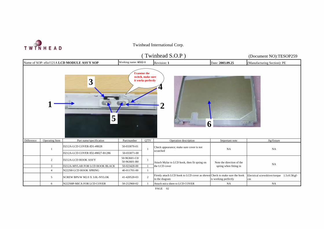
D212A-LCD COVER ID2-#8027-B1286 50-033071-00
3 D212A-MYLAR FOR LCD HOOK BLACK 50-023420-00 14 N222S8-LCD HOOK SPRING 40-011701-00 1
5 SCREW BPS/W M2.0 X 3.0L-NYLOK 41-420520-03 2 Firmly attach LCD hook to LCD cover as shownin the diagram
Check to make sure the hookis working perfectly
Electrical screwdriver/torque:1.5±0.5Kgf-cm
6 N222S8P-MICA FOR LCD COVER 50-212960-02 1 Attach mica sheet to LCD COVER NA NA
PAGE: 02
NA2
NA
Attach Mylar to LCD hook, then fit spring onthe LCD cover
Note the direction of thespring when fitting in
1
1 Check appearance; make sure cover is notscratched
( Twinhead S.O.P ) (Document NO):TESOP259Working name: 6512-1Name of SOP: efio!121A LCD MODULE ASS'Y SOP
D212A-LCD COVER-ID1-#8028 50-033070-01NA
50-963601-C0/50-963601-B0D212A-LCD HOOK ASS'Y
1
3
1 2
Twinhead International Corp.
4
5
Examine theswitch, make sureit works perfectly
6
Revision: 1 Date: 2003.09.25 (Manufacturing Section): PE
Explanation of illustration
Difference Operating Item Part name/specification Part/number Q'TY Operation description Important note Jig/fixture
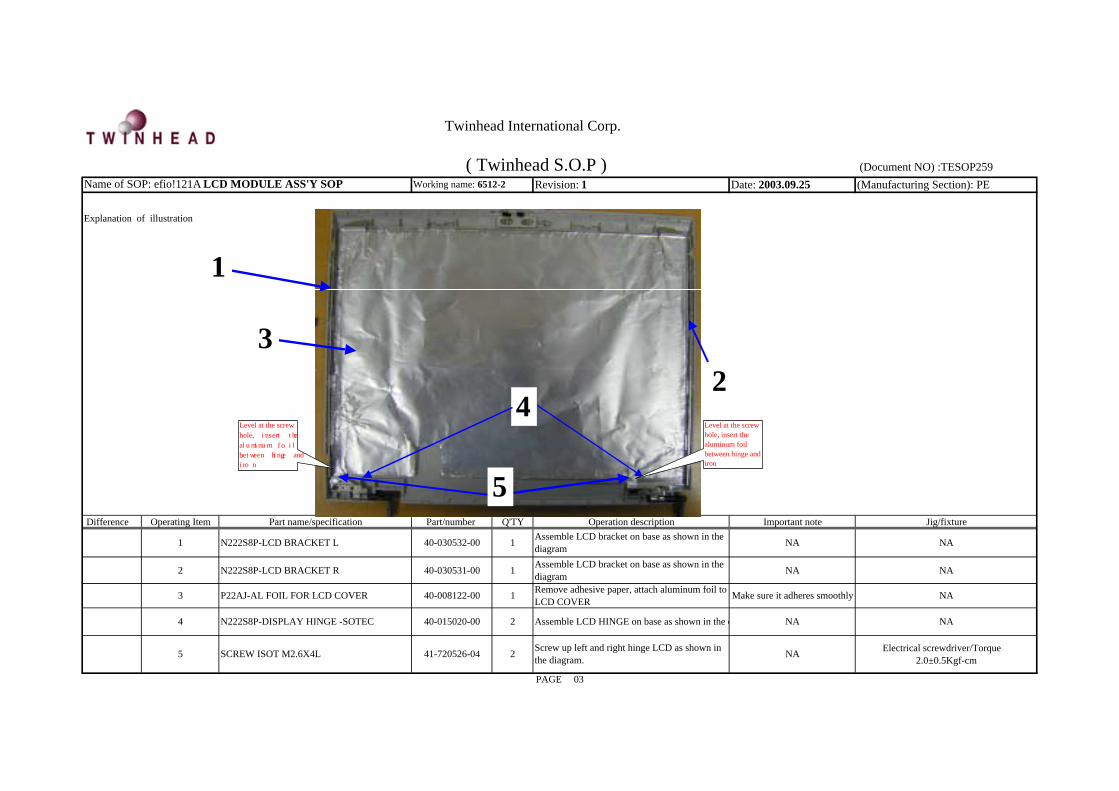
1 N222S8P-LCD BRACKET L 40-030532-00 1 Assemble LCD bracket on base as shown in thediagram NA NA
2 N222S8P-LCD BRACKET R 40-030531-00 1 Assemble LCD bracket on base as shown in thediagram NA NA
PAGE: 03
( Twinhead S.O.P ) (Document NO) :TESOP259Working name: 6512-2Name of SOP: efio!121A LCD MODULE ASS'Y SOP
P22AJ-AL FOIL FOR LCD COVER Make sure it adheres smoothly
NA Electrical screwdriver/Torque:2.0±0.5Kgf-cm
Screw up left and right hinge LCD as shown inthe diagram.241-720526-04SCREW ISOT M2.6X4L5
NA3 Remove adhesive paper, attach aluminum foil toLCD COVER40-008122-00 1
N222S8P-DISPLAY HINGE -SOTEC 40-015020-004 NAAssemble LCD HINGE on base as shown in the d NA2
2
1
3
Twinhead International Corp.
4
5
Level at the screwhole, insert thealuminum foil
between hinge and
iron
Level at the screwhole, insert thealuminum foilbetween hinge andiron

Revision: 1 Date: 2003.09.15 (Manufacturing Section): PE
Explanation of illustration
Difference Operating Item Part name/specification Part/number Q'TY Operation description Important note Jig/fixture
1 LCD-12.1" XGA TFT-TOSHIBA-LTD121LAOS-11 72-11223G-00 1 Check LCD panel to make sure surface is not
scratched NA NA
2 KEY PARTS BARCODE LABEL 63-250190-00 2 Attach key parts label NA NA
3 N222S1-HARNESS FOR HSD 12.1" LCD -SH640C 29-001640-00 1 Assemble LCD HARNESS on LCD CONN as
shown in the diagram NA NA
4 N222S8P-MYLAR FOR LCD HARNESS 50-023324-00 1 Place white Mylar on LCD wire material and LCDsystem
LCD wire material must restcompletely on the Mylar NA
5 KAPTON TAPE 27-319003-00 1 Attach between golden adhesive tape and LCDCONNECTOR as shown in the diagram NA NA
6 TAPE (6cm) 61-080007-01 1 Stick TAPE to fix LCD wire material Wire must be places at least 7cm from the edge NA
N222S8P-MYLAR_T FOR HYUNDAI LCD 50-023326-00 1 Tear off next Mylar; attach it aligned with upperside as shown in the diagram NA NA
N222S8P-MYLAR_R FOR HYUNDAI LCD 50-023327-00 1 Tear off next Mylar; attach it aligned with right sideas shown in the diagram NA NA
PasteTOSHIBA
LCD8 CONDUCTIVE SPONGE(10x0.5x40mm) 51-350094-15 1 Attach conductive sponge to LCD wire material as
shown in the diagramSponge must be aligned with
the black line NA
PAGE: 04
( Twinhead S.O.P ) (Document NO) :TEWorking name: 6512-4Name of SOP: efio!121A LCD MODULE ASS'Y SOP
PasteHyundai LCD 7
21 5 4
Twinhead International Corp.
2
6 6cm
3
8
7Align to
right side
Align to
upper side

Revision: 0 Date: 2003.09.01 (Manufacturing Section): PE
Explanation of illustration
Difference Operating Item Part name/specification Part/number Q'TY Operation description Important note Jig/fixture
1 SCREW ISOT-M2X3L-LOCKING 41-721520-03 2 Insert into LCD left and right racks as diagramshows. NA Electrical screwdriver/Torque:
1.5±0.5Kgf-cm
2 NA NA 1 Combine LCD and LCD COVER NA NA
3 INVERTER-5V-5W-FOR 12.1LCD 76-030105-00 1
4 DATE CODE LABEL 63-000041-XX 1
PAGE: 05
( Twinhead S.O.P ) (Document NO): TESOP259Working name: 6512-5Name of SOP: efio!121A LCD MODULE ASS'Y SOP
NAGet INVERTER and attach date code label NA
Connect INVERTER to LCD wire material andLCD panel NA0 NANA5 NA
Twinhead International Corp.
2
3 4
1
5

Revision: 0 Date: 2003.09.01 (Manufacturing Section): PE
Difference Operating Item Part name/specification Part/number Q'TY Operation description Important note Jig/fixture
2 TAPE 27-319003-00 1 Attach 6cm golden tape onto the inverter asshown in the diagram
Golden tape must cover theinverter tape stand
3 SCREW ISOT M2X3L 41-721520-03 4 Insert and tighten screws to the left and rightsides of the LCD as shown in the diagram NA Electrical screwdriver/Torque:
1.5±0.5Kgf-cm
Explanation of illustration
( Twinhead S.O.P ) (Document NO): TESOP25Working name: 6512-6Name of SOP: efio!121A LCD MODULE ASS'Y SOP
NA1 NA
PAGE: 06
Attach INVERTER to the base NA0 NA
LCD right side
LCD left side
3
Twinhead International Corp.
2
Scotch tape
fixed inverter
as diagram
shows
INVERTER snap close to
bottom and stick it
INVERTER fixed as
diagram shows:
1

Revision: 0 Date: 2003.09.01 (Manufacturing Section): PE
Difference Operating Item Part name/specification Part/number Q'TY Operation description Important note Jig/fixture
2 D212A-HOOK SUPPORT RUBBER-BLACK-E4677 52-002350-00 1 Attach support rubber to LCD panel
Rubber hole's position andpanel hole's position must
alignNA
3 double adhesive NA 2 Attach twin adhesive to LCD panel as shown in the d Do not extend tape over thepanel's edge NA
4 double adhesive NA 2 Attach twin adhesive to LCD panel as shown in the d Do not extend tape over thepanel's edge NA
5 NA NA NA Remove twin adhesive's other protective coat NA NA
PAGE: 07
Explanation of illustration
( Twinhead S.O.P ) (Document NO): TESOP259Working name: 6512-4Name of SOP: efio!121A LCD MODULE ASS'Y SOP
1 NA NAD212A-LCD PANEL#8126 FOR TH 50-034080-10 1 Check LCD panel to make sure surface is notscratched
Twinhead International Corp.
253
41

Revision: 0 Date: 2003.09.01 (Manufacturing Section): PE
Difference Operating Item Part name/specification Part/number Q'TY Operation description Important note Jig/fixture
1 NANAEmbed the panel and LCDNA
2
2
NANA
3 Electrical screwdriver/Torque: 2.0±0.5Kgf-cmTighten LCD PANEL as shown in the diagram
NA
SCREW ISOT-M2.6X6L NA41-721026-06
Tighten LCD PANEL as shown in the diagram41-721520-06
PAGE: 08
Electrical screwdriver/Torque: 1.5±0.5Kgf-cm2
( Twinhead S.O.P ) (Document NO): TESOP259Working name: 6512-8Name of SOP: efio!121A LCD MODULE ASS'Y SOP
Explanation of illustration
SCREW ISOT-M2X6L
Do not clip line
here
Twinhead International Corp.
1
2
3

Revision: 1 Date: 2003.09.25 (Manufacturing Section): PE
Difference Operating Item Part name/specification Part/number Q'TY Operation description Important note Jig /fixture
2 N222S8L-RUBBER PAD 50-020385-20 2 Attach rubber pad as shown in thediagram NA NA
3 N222S8L-RUBBER PAD 50-021268-20 2 Attach rubber pad as shown in thediagram NA NA
PAGE: 09
NANA
4 NA1NA NANA
( Twinhead S.O.P ) (Document NO): TESOP259Working name: 6512-11Name of SOP: efio!121A LCD MODULE ASS'Y SOP
Check appearance and make sure there areno scratches. Tear a protective cover stickbehind the panel
Place finished LCD panel into protectivebag
Explanation of illustration
1NANA1
13
Twinhead International Corp.
2

Twinhead International Corp.
REVISION: 3
PREPARED BY CONCURREDBY APPROVED BY
1. UPDATE RELEASE NA
efio!121A System setup instruction manual
DOCUMENT CODE:TESOP260
RELEASE DATE:
PAGE: 21 (total 21 page)
DESCRIPTION

Page/Version
1.Instruction manual P.01 Page Version Page Version Page Version Page Version
2.Fabricated material setup instruction (19 people required) P.02~P.20 1 3 19 0 2 0 20 0
3. References: 3 0
1. (D/C NO: KE3-0113) 4 1
2. (D/C NO: KE3-0010) 5 0
3. KE3-0058 6 1
7 1
4.Tool: Electrical screwdriver.tape.clip 8 1
9 0
10 0
10-1 0
11 0
12 1
13 1
14 0
15 1
16 2
BOM calls for real fabric; the numbers in the S.O.P are for reference only 17 0 This manual is for efio!121A model System setup 18 0
PAGE:01
(Document NO.): TESOP260REV: 3efio!121A Contents of System Ass'y S.O.P.
Twinhead International Corp.

Revision: 0 Date: 2003.09.01 (Manufacturing Section): PE
Difference Operating Item Part name/specification Part/number Q'TY Operation description Important note Jig/fixture
3 PRODUCT BAR CORD LABEL 63-000710-00 1 Attach PRODUCT BAR CORD LABEL on M/B as shownin diagram NA NA
Explanation of illustration
PAGE: 02
( Twinhead S.O.P ) (Document NO) : TESOP260Name of S.O.P.: efio!121A System Ass'y SOP Working name: 7051
1
182-873030-00
2CONDUCTIVE SPONGE(10X2X10mm) 51-350094-16
D212A-PCB ASS'Y-VI-K7-REV: 0-W/WIRELES
1
4 NA NA 1 Wipe M/B Bar code BARCODE machineNA
NAMYLAR must not cover LED light;
check PCMCIA and MEMORYSTICK rack for deformities
Get M/B, check to make sure MYLAR is correctly attached.Check Memory stick for deformities. Check Memory stickto make sure Mylar is properly attached. If all are correct.wipe the BARCODE
Attach sponge as shown in diagram NA NA
Twinhead International Corp.
1
23

Revision: 1 Date: 2003.10.14 (Manufacturing Section): PE
Difference Operating Item Part name/specification Part/number Q'TY Operation description Important note Jig/fixture
N222S1-RJ11 JACK HARNESS 29-001638-02
D212A-RJ11 JACK HARNESS-BLACK 29-001638-20
PRODUCT BAR CORD LABEL 63-000710-00 1 NA
The connection wire must plug into thecorrect position
NA
61-080022-00 1 Place modem HARNESS and fix with scotch tape asshown in diagram. NA
Attach KEY PARTS LABEL and PRODUCT BARCORD LABEL on MODEM as shown in diagram;wipe BARCODE
2
1
Assemble MODEM card on M/B; tighten two screws ina.b. sequence as shown in the diagram
BARCODE Machine
NAConnect wire as shown in diagram7 P22AJ-SB-USB FPC 29-015340-00 1
4
Electrical screwdriver/Torque: 1.5±0.5Kgf-cm
PAGE: 04
63-250190-00
6 SCREW ISOT M2.0 X 3.0L 41-721520-03
5 Scotch tape (約5~6cm) 61-080022-00
Scotch tape (約2~3cm)
1
( Twinhead S.O.P ) (Document NO) : TESOP260
Working name: 7053Name of S.O.P﹕efio!121A System Ass'y SOP
Explanation of illustration
MDC MODEM CARD-SMARTLINK-MDC56S-I
Check appearance to make sure there are no scratchesor damage76-060007-00 1
NA NA
KEY PARTS BARCODE LABEL
2Part numberaccording to
BOM
3
Place modem HARNESS and fix with scotch tape asshown in diagram1
NA NA
NANA Connect RJ11 JACK HARNESS on MODEM port1
NA
NA
5
6
a
b
Twinhead International Corp.
3
7
2
1
4

Revision: 0 Date: 2003.09.01 (Manufacturing Section): PE
Difference Operating Item Part name/specification Part/number Q'TY Operation description Important note Jig/fixture
4 Fragile Label 63-000041-XX 1 Attach LABEL as shown in diagram Do not attach to CPU chip centerarea NA
PAGE: 03
( Twinhead S.O.P ) (Document NO) : TESOP260Working name: 7053Name of S.O.P﹕efio!121A System Ass'y SOP
NA
KEY PARTS LABEL
2 NA
BAR CODE LABEL
Explanation of illustration
18-060004-F0 1 NAUse anti-static cloth to carefully wipe connecting partsSDRAM DDR SO-DIMM
1
NA
Insert SDRAM into M/B SOCKET NAConnecting part s must be cleanNA 1
NAAttach BAR CODE LABEL as shown in diagram63-250190-00 1
NA
When assembling CPU, turn in clockwise direction tolock; turn in counter-clockwise direction to unlock3 CPU-AMD K7 MOBILE ATHLON
XP 1500+-1333MHZ 01-2000H6-L0 Flat-headed screwdriver
5 63-250190-00
Do not touch CPU chip's center area
NAAttach K/P LABEL
1
1
1
2
4
3
5
Twinhead International Corp.

Revision: 1 Date: 2003.09.01 (Manufacturing Section): PE
Explanation of illustration
Difference Operating Item Part name/specification Part/number Q'TY Operation description Important note Jig/fixture
1 2nd FAN-L=80mm-W/SPONGE-6B0535AEV2 28-200022-11 1
Check fan's appearance to make sure there are noscratches or damage; tear off the adhesive tape from theback of the fan
Make sure fan's adhesive side and spongeare not damaged NA
2 NA NA 1 Use tools to attach fans to M/B's north bridge as shown indiagram
Note the position of wires when placingfans as shown in diagram. NA
3 Scotch tape (約2~3cm) 61-080022-00 3 Attach TAPE to fix wires; arrange as shown in diagram. Keep wires away from south and northbridge NA
( Twinhead S.O.P ) (Document NO) : TESOP260
PAGE: 05
Explanation of illustrationName of S.O.P﹕efio!121A System Ass'y SOP Working name: 7004
Fan's wire fixed with tape
and then attached at
bottom of the fan
Twinhead International Corp.
When arranging wires, do
not cover parts.3
2
1

Revision: 1 Date: 2003.10.14 (Manufacturing Section): PE
Explanation of illustration
Difference Operating Item Part name/specification Part/number Q'TY Operation description Important note Jig/fixture
1 P22AU-#8028M LOWER COVERKIT-P22T 77-630007-C0 1 Check bottom cover's appearance to make sure there are
no scratches or damageMake sure LAUNCH KEY is not
damaged or out of position NA
2 CONDUCTIVE SPONGE(5X1X20mm)
51-350100-00 1 Attach to bottom cover as shown in diagram Attach following plow groove onbottom cover NA
3 PRODUCT BAR CORD LABEL 63-000710-00 1 Attach PRODUCT BAR CORD LABEL as shown indiagram NA NA
4 NA NA 1Place M/B in LOWER COVER, arranging wires asshown in diagram. Plug fans wires into M/B; make surefan's position is correct and wires are hidden
NA NA
( Twinhead S.O.P ) (Document NO) : TESOP260
PAGE: 06
Name of S.O.P﹕efio!121A System Ass'y SOP Working name: 7004
2
Twinhead International Corp.
Arrange MODEM wires from LOWERCOVER's gap
4Wires must be attached belowpart
3
1

Revision: 1 Date: 2003.10.14 (Manufacturing Section): PE
Difference Operating Item Part name/specification Part/number Q'TY Operation description Important note Jig/fixture
1 Tape, narrow size (around 2~3cm) 61-080022-00 2 Arrange wires at bottom cover plow, use 2 pieces of tape tofix it as shown in diagram. NA Tape holder
P22AJ-PCB ASS'Y-VI-USB-REV: D 80-690000-00D 1
P22AJ-PROTECT RUBBER FORUSB-7.6x4x1.7t-E46220 52-002082-00 2
3 AL WASHER FOR USB BOARD-OD=8,ID=3,T=0.2mm 41-690130-02 1 Attach aluminum foil to USB card's left upper side as
shown in diagram. Aluminum foil must align with hole NA
4 AL WASHER FOR USB BOARD-OD=8,ID=3,T=0.3mm 41-690130-03 1 Attach aluminum foil to USB card's right lower side as
shown in diagram. Aluminum foil must align with hole NA
5 NA NA 1 Connect USB card and fix it at bottom cover right side asshown in diagram. NA NA
Explanation of illustration
PAGE: 07
( Twinhead S.O.P ) (Document NO) : TESOP260
Name of S.O.P﹕efio!121A System Ass'y SOP Working name: 7054
2 Get a USB card; attach 2 pieces of rubber to USB cardsshown in diagram. NA NA
Twinhead International Corp.
5
1 2
3
Arrange wires in plow. Donot place tape in CD-ROMassembly area. Tape mustnot extend over base edge.
When assembling RJ11,place side of MYLARwith writing in place first;do not damage MYLAR
4

Revision: 1 Date: 2003.09.25 (Manufacturing Section): PE
Difference Operating Item Part name/specification Part/number Q'TY Operation description Important note Jig/fixture
3 GASKET TAPE 10X10X0.7mm 27-300051-00 1 Attach sponge in the middle of USB card as shown indiagram
NA NA
4 P22AJ-RUBBER FOR USB-4X2mm,T=2mm 52-002080-00 1 Attach RUBBER vertically along LOWER COVER
as shown in diagram; tightly press on USB cardMake sure RUBBER tightly pressedon USB card and fix it in position. NA
Name of S.O.P﹕efio!121A System Ass'y SOP Working name: 7055
27-319009-00
CONDUCTIVE SPONGE5X3.5X15mm
( Twinhead S.O.P ) (Document NO) : TESOP260
1 NAAttach yellow tape to parts as shown in diagram Do not cover surrounding buttons
Attach along to red line; do go overred line. NAAttach conductive sponge to M/B as shown in
diagram1
PAGE: 08
Explanation of illustration
51-350094-02 1
2 Yellow anti-static tape(12X25mm)
2
Attach anti-static tape to parts,but not on button.
Twinhead International Corp.
34
1

Revision: 0 Date: 2003.09.01 (Manufacturing Section): PE
Difference Operating Item Part name/specification Part/number Q'TY Operation description Important note Jig/fixture
4 Tape, narrow size (around 2~3cm) 61-080022-00 1 Use tape to fix USB card's wires as shown indiagram.
Make sure wires are properlyconnected. Scotch tape
( Twinhead S.O.P ) (Document NO) : TESOP260
Explanation of illustrationName of S.O.P﹕efio!121A System Ass'y SOP Working name: 7007
Wipe CD-ROM bar code
P22T-#8028 QUANTA DVD-ROMKIT1 77-634008-10 Assemble COMBO on M/B in position as shown
PAGE: 09
2 KEY PARTS LABEL 63-250190-00 1 NA bar code machine
3 CONDUCTIVESPONGE(5X0.5X85mm) 51-350094-10 1 Attach alignment sponge to CD-ROM/COMBO's
back edge
NA1
Attach along red line NA
25mm
20mm
1
Twinhead International Corp.
3
4

Revision: 0 Date: 2003.09.01 (Manufacturing Section): PE
Difference Operating Item Part name/specification Part/number Q'TY Operation description Important note Jig/fixture
1 D212A-#8028 UPPER COVER KIT 77-636007-00 1 Assemble upper cover kit on base foundation.When assembling UPPER COVER,the RIB must be fixed in the proper
position.NA
2 NA NA 1 Check the upper cover; do not cover 5 LED lights. NA NA
NAAttach it vertically above red line asshown in diagram.4 CONDUCTIVE SPONGE
(10X0.5X45mm) 51-350094-15 1
PAGE: 10
Explanation of illustrationName of S.O.P﹕efio!121A System Ass'y SOP Working name: 7055
341-850520-06SCREW ISOP M2.0 X 6.0L3
Attach conductive sponge to upper cover left uppercorner as shown in diagram.
Do not touch UPPER COVER's ironplate; if there is dirt, use cleanser to
remove.
( Twinhead S.O.P ) (Document NO) : TESOP260
Electrical screwdriver/Torque:1.5±0.5Kgf-cm
Tighten 2 screws on upper cover in a order a.b c asshown in diagram.
4a
b
c
3
Twinhead International Corp.
2The UPPER COVER's ribmust be attached to base rib'sleft side.
1Attach conductive
sponge stick along
this red line.

Revision: 0 Date: 2003.09.25 (Manufacturing Section): PE
Difference Operating Item Part name/specification Part/number Q'TY Operation description Important note Jig/fixture
1 White scotch tape NA 1 Attach tapes at keyboard wire's bottom Do not tape over the edge of thekeyboard. NA
2 Double-sided adhesive tape T4000 NA 4 Attach 4 double-sided adhesive tapes as shown in diagram andremove other side to make it adhesive NA NA
PAGE: 10-1
Explanation of illustration
( Twinhead S.O.P )
Name of S.O.P﹕efio!121A System Ass'y SOP Working name: 7057
When part'scomes
without tapesthen need to
do this
Twinhead International Corp.
1
2

Revision: 0 Date: 2003.09.25 (Manufacturing Section): PE
Difference Operating Item Part name/specification Part/number Q'TY Operation description Important note Jig/fixture
1 K/B-85 KEY-TW-N222S8SA-JME-FOR SOTEC 71-710101-00 1 Check the keyboard make sure printing is not fuzzy or damaged;
use cleaner to clean iron plate.
Make sure K/B's RUBBER isnot over banded as shown indiagram
NA
2 KEY PARTS LABEL 63-250190-00 1 Attach KB onto KEY PARTS LABEL; wipe BARCODE NA bar code machine
3 NA NA 1 Connect KB's wires on M/B's CONN as shown in diagram Connect tightly NA
4 NA NA 0 Fix K/B on UPPER COVER as shown in diagram.
Check hook for damage. Notethat K/B upper side must fitfirmly in UPPER COVERhook; make sure wires are notvisible from front side.
NA
PAGE: 11
( Twinhead S.O.P ) (Document NO) : TESOP260
Name of S.O.P﹕efio!121A System Ass'y SOP
Explanation of illustration
Working name: 7057
4
Twinhead International Corp.
Make sure K/B RUBBERis not over banded
3
Make sure wires are notvisible from front side.
1 2

Revision: 1 Date: 2003.10.14 (Manufacturing Section): PE
Difference Operating Item Part name/specification Part/number Q'TY Operation description Important note Jig/fixture
WIRELESS LEN MODULE 76-070005-00 1
KEY PARTS LABEL 63-250190-00 1
PRODUCT BAR CORD LABEL 63-000710-00 1
2 NA NA 1 Plug wireless antenna into transmission card as shownin diagram. Connect as shown in diagram.NA
3 P22T rubber for wireless 52-003091-00 2 Attach 2 rubber pieces to wireless card as shown indiagram
When attaching rubber, do
cover card's edge or
card's electrical parts.NA
4 SCREW ISOT-M2X3L-SELF-LOCKING 41-721520-03 2 Tighten two screws (M2X3) on wireless transmissioncard and fix it on M/B
When tightening, make sure
rubber doesn't not extend
over card's edge
Electrical screwdriver/Torque:
1.5±0.5Kgf-cm
PAGE: 12
1Plug wireless card wire into M/B. Attach KEY PARTSLABEL and PRODUCT BAR CORD LABEL on M/Bas shown in diagram. Wipe BARCODE
BAR CODE machineNA
5 Tape, narrow size (around 3~4cm) 61-080022-00 2
( Twinhead S.O.P ) (Document NO) : TESOP260
Name of S.O.P﹕efio!121A System Ass'y SOP Working name: 7008
Explanation of illustration
Attach 2 pieces of tape to fix wires as shown indiagram.
Wires must be attached
flat on board; do not bandNA
Twinhead International Corp.
Plug wires fromhere
2
3
1
4
Plug wireless antennainto transmission cardat 45 degree angle5

Revision: 1 Date: 2003.10.14 (Manufacturing Section): PE
Difference Operating Item Part name/specification Part/number Q'TY Operation description Important note Jig/fixture
3 Tape (約2~3cm) 61-080022-00 1 Connect SPEAKER wires to M/B CONN; fix withtape.
Wires need to be arranged in astraight line and not interfere with
iron parts.膠台
4 NA NA 1Connect PALM REST TOUCHPAD's wires to M/B;insert PALM REST into BASE and make sure K/Bwires are not visible.
Insert FFC. If there is rugged edge onLOWER COVER hook, tidy it up it
before assembling鑷子
D212A-CAP FOR WL SWITCH-#8735 50-041100-10
P22AU-CAP FOR WL SWITCH-#8028 50-041100-00PAGE: 13
NA NADate mark2 63-000042-XX 0 Attach date mark to palm rest panel's iron part asshown in diagram.
Explanation of illustration
NA 77-636009-10 1 Check appearance to make sure there are no scratchesor damage NA1 D212A-#8028 PALM REST KIT-
W/WIRELESS LAN
( Twinhead S.O.P ) (Document NO) : TESOP260
Name of S.O.P﹕efio!121A System Ass'y SOP Working name: 7008
Note arrangement of CAP wires;arrange wires as shown in diagram. NAConnect CAP to M/B's connector as shown in diagram.5 1
1
Twinhead International Corp.
3
2
4
Check left and right buttons:Press each button's fourcorners separately. Replace ifthere are any obviousdifferences in clicking
Check up and down buttons: Presseach button's four cornersseparately. Replace if there are anyobvious differences in clicking
5

Revision: 0 Date: 2003.09.01 (Manufacturing Section): PE
Difference Operating Item Part name/specification Part/number Q'TY Operation description Important note Jig/fixture
1 NA NA 1 Wipe CPU and Barcode product labels NA Bar code machine
3 SCREW ISOT M2.0 X 3.0L 41-721520-03 2 Tighten 2 screws on bottom cover as shown in diagram. NA Electrical screwdriver/Torque: 1.5±0.5Kgf-cm
Explanation of illustration
PAGE: 14
( Twinhead S.O.P ) (Document NO) : TESOP260Name of S.O.P﹕efio!121A System Ass'y SOP Working name: 7058
2 SCREW ISOP M2.0 X 6.0L 41-850520-06 5 NATighten 5 screws on LOWER COVER in a.b.c.d.e order as shownin diagram. Electrical screwdriver/Torque: 1.5±0.5Kgf-cm
a b
2e
dc
Twinhead International Corp.
3
1

Revision: 1 Date: 2003.10.14 (Manufacturing Section): PE
Difference Operating Item Part name/specification Part/number Q'TY Operation description Important note Jig/fixture
SCREW ISOP M2.0 X 6.0L 41-850520-06
3 NA NA 1Arrange wires: Place LCD's wires under bottom dent理;connect LCD wires to M/B. Arrange wires as shown in diagram. N/A
PAGE: 15
Name of S.O.P﹕efio!121A System Ass'y SOP Working name: 7009
1 #8028 DISPLAY ASS'Y-12.1" XGATFT-FOR HYDIS-D21 86-636905-10 1
Explanation of illustration
Electrical screwdriver/Torque:2.0±0.5Kgf-cm
Tighten HINGE SCREW on upper cover in a.b. order asshown in diagram. Open LCD at both hinges and shake3-4 times before tightening.
Before locking the screws, make sure theLCD does not rise up at an angle to the base
.
( Twinhead S.O.P ) (Document NO) : TESOP260
Take LCD, wipe BARCODE and install LCDMODULE on BASE MODULE
Do not damage upper cover whenassembling. When installing LCD, makesure both hinges are installed at the same
angle
bar code machine
22
3
1
Twinhead International Corp.
ab
2
Both hinge must be installedhorizontally

Revision: 2 Date: 2003.10.14 (Manufacturing Section): PE
Difference Operating Item Part name/specification Part/number Q'TY Operation description Important note Jig/fixture
1 Heatsink for CPU fan 27-330000-00 1 Attach a heatsink onto CPU fan. Make sure heatsink's size is same as redmarked area as shown in diagram. NA
2 CONDUCTIVE SPONGE(5-2-15mm) 51-350094-01 2 Attach two conductive sponges to fan as shown
in diagram. NA NA
3 P22AJ-HEATSINK MODULE W/FAN-SCREW THREAD=2.2mm 40-003510-11 1 NA
4 NA NA 3
PAGE: 16
Arrange wires beside fan; do not let fancover wires as shown in diagram.
Name of S.O.P﹕efio!121A System Ass'y SOP
( Twinhead S.O.P ) (Document NO) : TESOP260
Take HEAT SINK MODULE and connectwires on M/B. Fix with 3 spring screws ina.b.c order; arrange wires as shown in diagram.
Explanation of illustrationWorking name: 7010
2
3
Twinhead International Corp.
1
a
b
c
Use hand press beforetightening a.b.c. screws.
Arrange wires;insert from here.
4

Revision: 0 Date: 2003.09.01 (Manufacturing Section): PE
Difference Operating Item Part name/specification Part/number Q'TY Operation description Important note Jig/fixture
PAGE: 17
( Twinhead S.O.P ) (Document NO) : TESOP260
Explanation of illustration
Working name: 7011
1 SCREW ISOT M2.6 X 5.0L 41-721526-05 2 Electrical screwdriver/Torque:2.5±0.5Kgf-cm
Lock HINGE SCREW on bottom cover in a.b.order as shown in diagram. Screws must lock tight.
Name of S.O.P﹕efio!121A System Ass'y SOP
2 N222S1-HARNESS COVER 40-002311-00 1 NAAssemble Harness cover on LCD wires asshown in diagram. Do not damage bottom cover.
3 P22AJ-RUBBER FOOT-PANTONE 428C 52-000000-20 1 Attach RUBBER FOOT to fillister. N/A NA
Twinhead International Corp.
ba
1
2
3

Revision: 1 Date: 2003.09.01 (Manufacturing Section): PE
Difference Operating Item Part name/specification Part/number Q'TY Operation description Important note Jig/fixture
2 P22AJ-RAM DOOR 50-022150-70 1 Install RAM DOOR NA NA
3 D212A-MYLAR FOR RAM DOOR-BLACK 50-023421-00 1 Attach Mylar as shown in diagram. NA NA
4 SCREW ISOP M2.0 X 3.0L 41-721520-03 2 Tighten two screws on ram door as shownin diagram. NA Electrical screwdriver/Torque:
1.0±0.5Kgf-cm
( Twinhead S.O.P ) (Document NO) : TESOP260
N/A
Install CPU DOOR into BASE MODULEas shown in diagram
Make sure the CPU DOORcompletely lodged in.
P22AJ-RUBBER FOOT-PANTONE428C5
Name of S.O.P﹕efio!121A System Ass'y SOP Working name: 7060
Explanation of illustration
NA11 P22AJ-CPU DOOR ASS'Y 50-963001-20
150-000000-20 Attach rubber foot to fillister
PAGE: 18
NA
Twinhead International Corp.
1
5
24
Note: CPU DOOR hookmust completely fit in
Check CPU cover: Itmust not be loose asshown in the diagram
3

Revision: 0 Date: 2003.09.01 (Manufacturing Section): PE ( Twinhead S.O.P ) (Document NO) :TESOP260
PAGE: 19
Name of S.O.P﹕efio!121A System Ass'y SOP Working name:
Explanation for illustration
LCD Moduleand Hinge CapGap=<1.5mm
LCD Moduleand Hinge CapGap=<1.5mm
Upper cover andbottom coverGap=<0.9mm
(1)LCD andPanelGap=<1.0m
1
2
3
4
LCD Module's fourcorner Gap=<0.8mm
CD-ROM's Functionmust work properly.
Bottom coverBezel
Upper cover andBezel5
K/B and uppercoverGap=<0.3mm
Battery andupper coverGap=<1.0mm
Upper cover andpalm restGap=<0.3mm
Upper cover andpalm restGap=<0.3mm
6
CD-ROM Bezel andbottom coverGap=<1.4mm
CPU Door andbottom coverGap=<0.8mm
Battery and bottomcoverGap=<0.95mm
This area is not
included in testing
RAM Door andbottom coverGap=<0.8mm
7
8 Gap=<0.2mm
Twinhead International Corp.
Gap=<0.8mm
GAP=<0.5mm
Palm rest andbottom
0 5
GAP=<0.5mm
Bottom and upper coverGap=<0.3mm

T w inhead International Corp.
REVISION: 0
PREPARED BY CONCURREDBY APPROVED BY
1. NEW RELEASE PE:
DESCRIPTION
efio!121A (Complete set) Instruction Manual
DOCUMENT CODE:TESOP284
RELEASE DATE:
PAGE: 11 (total 11 page)

Page/Version: REV: 0Page Version Page Version Page Version Page Version
1.Instruction manual P.01 1 02.Fabricated material setup instructions p.02~p011 2 0
3 04 0
5 0 6 03.Tool-Screwdriver, scotch tape 7 0
8 09 0
10 0
11 0
BOM calls for real fabric; the numbers in the S.O.P are for reference only
This manual is for efio!121A model 2-IN-1(Complete set) Packaging instruction manualPAGE:01
(Document NO.): TESOP284
efio!121A(Complete set) Packaging instruction manual
Twinhead International Corp.

Working name: 9101-1 Revision: 0 Date: 2003.09.08 (Manufacturing Section: PEExplanation of illustration
Difference Operating Item Part name/specification Part/number Q'TY Operation description Important note Jig/fixture
2 NA NA 1 Adhere HDD rack's scotch tape on HDD surface asshown in the diagram NA NA
4 tape 61-080022-00 1 Attach scotch tape near bus line and M/B as shownin the diagram NA NA
5 tape 61-080022-00 1 Attach scotch tape near bus line and M/B as shownin the diagram NA NA
6 NA NA 1 Assemble palm rest on the machine; make surepalm rest's connection line is not lost. NA NA
PAGE: 02
NA
3 HDD RUBBER 52-002020-00 1 Assemble HDD's rubber beside HDD as shown inthe diagram NA NA
1 HDD ASS'Y
( Twinhead S.O.P ) ( Document NO):TESOP284Name of S.O.P:efio!121A Final Ass'y S.O.P
86-630004-XX 1 Install HDD Make sure HDD is pluggedinto M/B
6
Twinhead International Corp.
13
25
4

Working name : 9101-2 Revision: 0 Date: 2003.09.08 (Manufacturing Section) : PEExplanation of illustration
Difference Operating Item Part name/specification Part/number Q'TY Operation description Important note Jig/fixture
PAGE: 03
NA NA Start up machine; enter BIOS setup screen and makesure HDD is listed
According to testing instructionmanual
( Twinhead S.O.P ) ( Document NO):TESOP284Name of S.O.P: efio!121A Final Ass'y S.O.P
1 NA NA
Twinhead International Corp.
1

Working name : 9101-3 Revision: 0 Date: 2003.09.08 (Manufacturing Section): PEExplanation of illustration
Difference Operating Item Part name/specification Part/number Q'TY Operation description Important note Jig/fixture
2 BAT-LIION-3S2P-2KmAh 23-050000-23 1 Remove battery horizontally Horizontally remove it NAPAGE: 04
41-850520-06 7 Tighten screws in in proper order: a.b.c.d.e.f.g asshown in the diagram NA1 SCREW ISOP M2X6L
( Twinhead S.O.P ) ( Document NO):TESOP284Name of S.O.P: efio!121A Final Ass'y S.O.P
Electrical screwdriver/torque: 1.5±0.5Kgf-cm
a
bc
de
f g
Twinhead International Corp.
1 2

Revision: 0 Date: 2003.09.08 (Manufacturing Section): PEExplanation of illustration
Pls refer to Quality assurance standard
( Twinhead S.O.P ) ( Document NO):TESOP284
PAGE: 05
Name of S.O.P:efio!121A Complete set Ass'y SOP Working name:
(1)LCD and PanelGap=<0.8mm1
Bottom andbottom coverGap=<0.8mm
Step=<0.5mm Step=<0.5mm2
LCD Module and HingeCap的Gap=<1.5mm
LCD Module and Hinge Cap的Gap=<1.5mm
3
Upper cover andbottom coverGap=<0.8mm
4
LCD Module and four cornerGap=<1.0mm
This e\area is notincludes forexamination, but CD-ROM's functionshould be OKBottom and Bezel
Gap=<1.0mm
Upper cover andBezel Gap=<1.0mm5
K/B and uppercoverGap=<0 5mm
Gap=<0.8mm
Battery and uppercover Gap=<1.0mm
Upper cover andpalm restUpper cover and palm
rest Gap=<0.5mm
6
CD-ROM Bezel bottomcover Gap=<1.4mm
CPU Door andbottom covercap=<0.8mm
Battery and bottomcover Gap=<0.6mm
This e\area
do not
include for
examine
RAM Door and bottomcover Gap=<0.8mm
7
For specific spec. Pls refer
to Quality assurance
standard
8Gap=<0.2mm
Twinhead International Corp.
Right side is
locked

Working name : 9101-5 Revision: 0 Date: 2003.09.08 (Manufacturing Section): PE
Difference Operating Item Part name/specification Part/number Q'TY Operation description Important note Jig/fixture
1 SCREW RUBBER 52-002021-00 2 Attach as shown in diagram a and b Press the RUBBER into the fillister,ensure the RUBBER cannot be scarred. NA
D212A-HINGE COVER L 50-035142-30 1
D212A-HINGE COVER R 50-035141-30 1
( Twinhead S.O.P ) ( Document NO): TESOP284
Explanation of illustrationName of S.O.P. : efio!121A Complete set Ass'y SOP
2Assemble HINGE CAP L,R at left and rightsides of BASE MODULE as shown in thediagram
PAGE: 06
When assembling, right hinge capmust fit it in at an angle; To preventhinge breakage, DO NOT fit invertically!
NA
Twinhead International Corp.
Behind left Behind right
1a b
2Left Right

Working name : 9101-6 Revision: 0 Date: 2003.09.08 (Manufacturing Section): PE
Difference Operating Item Part name/specification Part/number Q'TY Operation description Important note Jig/fixture
NA
PAGE: 07
( Twinhead S.O.P ) ( Document NO):TESOP284
Explanation of illustrationName of S.O.P. :efio!121A Complete set Ass'y SOP
Part numberaccording to
BOM1 D212A-LCD FRONT PLATE-ID1-FOR
TWINHEAD NA40-006121-00 1 Attach LCD COVER pit: Direction is as perclient's request
Twinhead International Corp.
1

Revision: 0 Date: 2003.09.08 (Manufacturing Section): PE
Difference Operating Item Part name/specification Part/number Q'TY Operation description Important note Jig/fixture
1 ALL MODEL-LOGO STICKER ONN/B FOR WIN XP 63-000538-30 1 Attach PALM REST in right upper corner beside the
INTEL STICKER as shown in the diagram NA NA
2 D212A-FCC LABEL SYSTEM-C3435-FOR GENERIC 63-040100-Q0
1Attach of front side of palm rest. Do not cover TOUCHPAD's edge NA NA
Part numberaccording to BOM 3 D212A-LABEL FOR 2003
TAIWANESE MARKET 63-000823-B0 1 Attach label at the bottom of the machine as shown in thediagram NA NA
PAGE:08
( Twinhead S.O.P ) ( Document NO):TESOP284
Explanation of illustrationWorking name:9101-7Name of S.O.P: efio!121A Complete set Ass'y SOP
2
Twinhead International Corp.
13

Working name: Paste protective cover Revision: 0 Date: 2003.09.08 (Manufacturing Section): PE
Difference Operating Item Part name/specification Part/number Q'TY Operation description Important note Jig/fixture
1 P22AJ-PROTECTIVE SHEET PLATE 50-000203-00 1 Tear off plastic paper on protective spacer Do not touch the surface of theprotective spacer NA
2 NA NA NA Use anti-static brush to remove dirt Brush GENTLY; do notdamage the LCD screen NA
3 NA NA 1 Place LCD protective spacer on LCD screen Center protective spacer; Makesure no dust is on spacer NA
4 N222S8PII-CLEAR LABEL 63-000940-00 4 Attach paster at four corners to stabilize protectivespacer
Do not directly touch protectivespacer . Plastic clip
Explanation of illustration
PAGE: 9
( Twinhead S.O.P ) ( Document NO):TESOP284Name of S.O.P: N222S8PⅡ Final Ass'y S.O.P
34
4
Use anti-static
brush to clean dirt
Place LCD protective spacer on LCDscreen
Attach
paster at four corner to stabilize
Twinhead International Corp.
1 2
Working name : Revision: 0 Date: 2003.09.08 (Manufacturing Section): PE
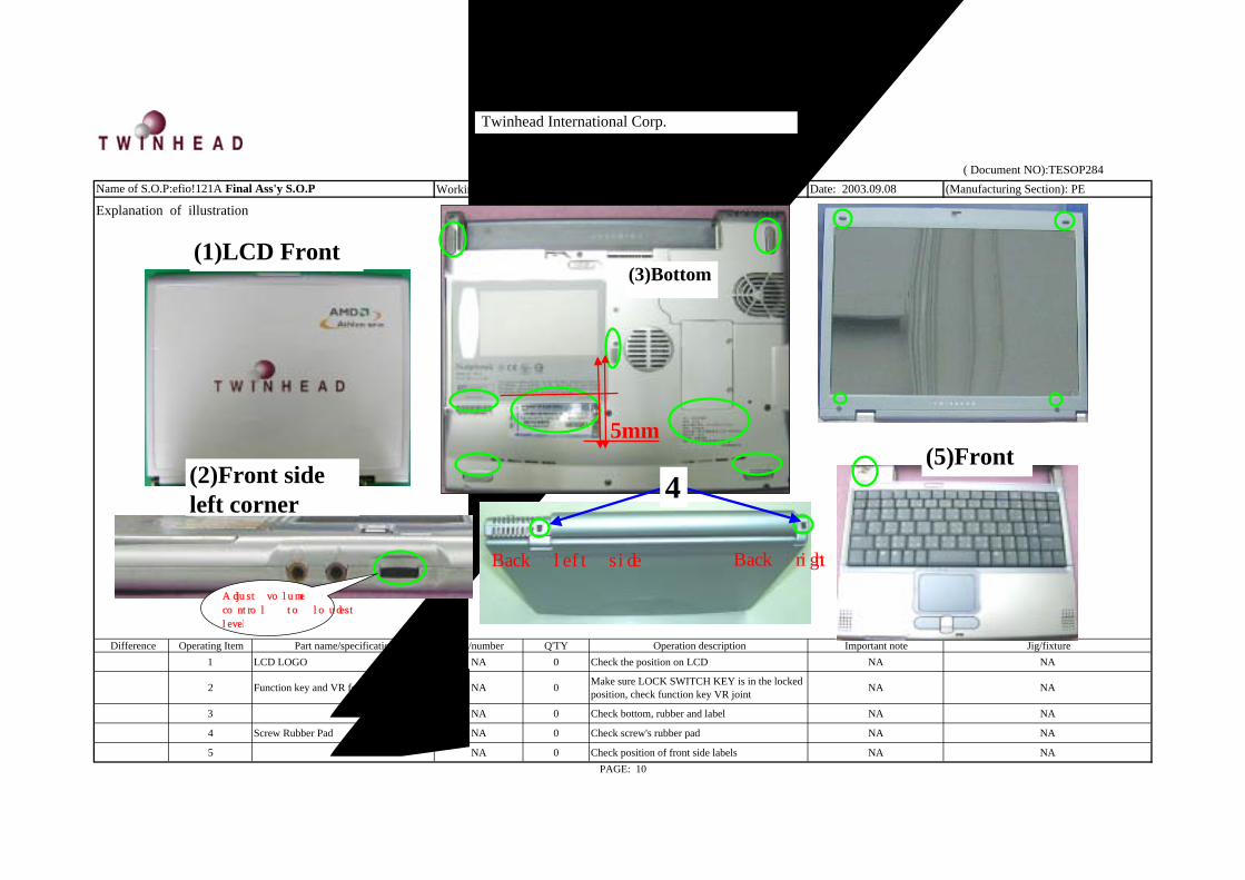
Difference Operating Item Part name/specification Part/number Q'TY Operation description Important note Jig/fixture1 LCD LOGO NA 0 Check the position on LCD NA NA
2 Function key and VR felling NA 0 Make sure LOCK SWITCH KEY is in the lockedposition, check function key VR joint NA NA
3 機台底部 NA 0 Check bottom, rubber and label NA NA
4 Screw Rubber Pad NA 0 Check screw's rubber pad NA NA
5 機台正面 NA 0 Check position of front side labels NA NA
Explanation of illustration
PAGE: 10
( Twinhead S.O.P ) ( Document NO):TESOP284Name of S.O.P:efio!121A Final Ass'y S.O.P
(2)Front sideleft corner
(1)LCD Front
Adjust volume
control to loudest
level
Twinhead International Corp.
(3)Bottom
Back left sideBack right side
4
5mm(5)Front

Revision: 0 Date: 2003.09.08 (Manufacturing Section): PE
Difference Operating Item Part name/specification Part/number Q'TY Operation description Important note Jig/fixture
Part numberaccording to
BOM1
N222S8P-MICROSOFT COASTICKER-FOR WINXP HOMEEDITION
63-910115-41 1 Attach COA LABEL as diagram shows; make certain COAserial no. is visible
Do not cross over red line whenattaching the label NA
PAGE:11
( Twinhead S.O.P ) ( Document NO):TESOP284
Explanation of illustrationWorking name:9101-10Name of S.O.P: efio!121A Complete set Ass'y SOP
1
Twinhead International Corp.
5mm

Tw inhead International Corp.
REVISION: 0
PREPARED BY CONCURRED BY APPROVED BY
1. NEW RELEASE PE: QA:
DESCRIPTION
efio!121A (CARRYING BAG) PackagingInstruction Manual
DOCUMENT CODE:TESOP029
RELEASE DATE:
PAGE: 5 (total 5 page)

efio!121A (CARRY BAG) Packaging instruction manual
Page/Version: REV: 0
Page Version Page Version Page Version Page Version
1.Instruction manual P.01 1 0
1.Fabricated material setup instructionP.02~P.05 2 0
3 0
4 0
5 0
BOM calls for real fabric; the numbers in the S.O.P are for reference only
PAGE: 01
(Document NO.): TESOP
efio!121A (CARRYING BAG) Packaging Instruction Manual
Twinhead International Corp.

Working name: 9001-1Revision:0 Date: 2003.08.08 (Manufacturing Section): PE
Explanation of illustration
Difference Operating ItemPart name/specification Part/number Q'TY Operation description Important note Jig/fixture
1ADAPTER-20V-60W 76-010562-00
Check appearance to make sure the
part is not scratched
2 DATE CODE LABEL 63-000042-XXAttach the LABEL as shown in the
diagram
3 NA NAUse factory provided plastic bag, put
the ADAPTER in
4POWER CORD FOR US/PL/KR/C 29-020181-10
Check appearance to make sure the
part is not scratchedNA
PAGE: 02
( Twinhead S.O.P ) ( Document NO): TESOP
Name of S.O.P: efio!121A Carry Bag PACKING Ass'y SOP
1 NA
Operate according to BOM
4
Twinhead International Corp.
1 2 3

Working name: 9001-2Revision:0 Date: 2003.08.08 (Manufacturing Section): PEExplanation of illustration
Difference Operating Item Part name/specification Part/number Q'TYOperation description Important note Jig/fixture
1 USER'S MANUAL-TW-R:01 62-030150-01
3 MICROSOFT MANUAL 62-10B001-30
4 CUSTOMER FEEDBACK LIST-TW 62-090010-10
5 CD TABLE SHEET -US-R:00 62-400210-00
6 UL CAUTION SHEET-US/FR 62-600237-01
7 RECOVERY CD FOR DRIVE 70-140372-00
8 RECOVERY CD FOR HDI-TW 70-140370-00
9 DR.EXE 2002 CD 70-140470-10
10
CATALOG CHINESE TRADITIONAL-TWINHEAD
AGENCY PRODUCTS-VER 1.0-ALL M62-090122-00
11
CATALOG CHINESE TRADITIONAL-TWINHEAD
FAMILY-VER 1.0-ALL MODEL62-090120-00
12
CATALOG CHINESE TRADITIONAL-TWINHEAD
WIRELESS PRODUCTS-VER 1.0-ALL62-090121-00
13 modem cable 29-130244-00
14 PLASTIC BAG 35cmX25cm FOR CD/MUN60-010070-00
Place all items in lists 1~9 &13 into PE
BAG and seal with scotch tape
( Twinhead S.O.P ) ( Document NO): TESOP
Name of S.O.P: efio!121A Carry Bag PACKING Ass'y SOP
PAGE: 03
1
Check appearance to make sure the items are n
The specific LIST
according BOMNA
Check appearance to make sure the item is
not scratched
14
9
12
8
11
7
10
13
Twinhead International Corp.
4
3 1
65
2

Working name: 9001-3Revision:0 Date: 2003.08.08 (Manufacturing Section): PEExplanation of illustration
Difference Operating Item Part name/specification Part/number Q'TYOperation description Important note Jig/fixture
1 PAPER CUSHION FOR EX-FDD61-007050-00 Assemble the box as shown in the diagram NA NA
2 USB FDD
70-113144-10Check appearance to make sure the part is
not scratched.
If customer do not
purchase FDD, skip the
following steps
3 FCC LABEL FDD TWINHEAD 63-040101-00 Attach the LABEL as shown in the diagram
4 KEY PARTS LABEL 63-000042-XX Attach the LABEL as shown in the diagram
5 PE-BAG 200X150mm 60-010026-00 Place FDD into plastic bag
6 NA NA 0 Place FDD into box and position it well.
PAGE: 04
1
( Twinhead S.O.P ) ( Document NO): TESOP
Name of S.O.P: efio!121A Carry Bag PACKING Ass'y SOP
1
2
3
4
56
Twinhead International Corp.
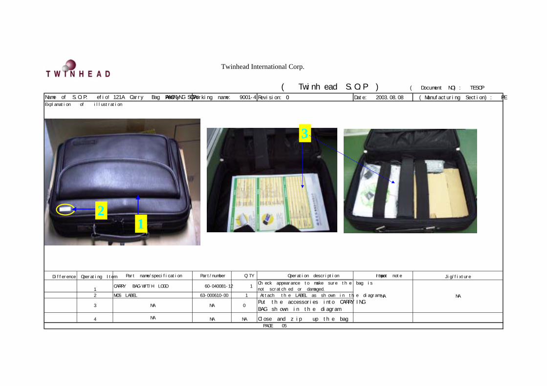
Working name: 9001-4Revision: 0 Date: 2003.08.08 (Manufacturing Section): PEExplanation of illustration
Difference Operating ItemPart name/specification Part/number Q'TY Operation description Important note Jig/fixture
1CARRY BAG-W/T/H LOGO 60-040081-12 1
Check appearance to make sure the bag is
not scratched or damaged.
2 MOS LABEL 63-000610-00 1 Attach the LABEL as shown in the diagram
3 NA NA 0Put the accessories into CARRYING
BAG shown in the diagram
4 NA NA NA Close and zip up the bag
( Twinhead S.O.P ) ( Document NO): TESOP
Name of S.O.P: efio!121A Carry Bag PACKINGAss'y SOP
PAGE: 05
NA NA
21
3
Twinhead International Corp.
REVISION: 0
PREPARED BY CONCURRED BY APPROVED BY
1. NEW RELEASE PE: NA
DESCRIPTION
efio!121A 2-IN-1 Packing S.O.P.
DOCUMENT CODE:TESOP285
RELEASE DATE:
PAGE: 8 (total 8 page)
Twinhead International Corp.

Twinhead International Corp.
(Document NO.):TESOP285
Page/Version REV: 0
Page Version Page Version Page Version Page Version
1. Instruction manual P.01 1 0
2. Fabricated material setup instructionsP.02~P.08 2 0
3 0
4 0
5 0
6 0
7 0
8 0
BOM calls for real fabric; the numbers in the S.O.P are for reference only
This manual is for efio!121A model 2-IN-1 W/ACCESSORY BOX packaging
efio!121A 2-IN-1Packaging Instruction Manual
PAGE:01
efio!121A 2-IN-1 W/ACCESSORY BOX Packaging/Instruction Manual

Working name:
9102 9501-1 Revision: 0 Date: 2003.09.08 (Manufacturing Section): PE
Explanation of illustration
Difference Operating Item Part name/specification Part/number Q'TY Operation description Important note Jig /fixture
1 NANA 0
Double check the serial numbers.
Numbers on the machine and procedures
card should be the same
NA NA
2 PROTECTION PAPER FOR K/B 61-015060-00 1 Place K/B protective cotton sheet on the machineThe dent of the sheet
must align with
machine's dent
NA
3 PROTECTION PAPER FOR SYSTEM 61-015061-00 1 Place the machine into protective cotton
bagNA NA
4 Scotch tape (3CM) 27-319005-00 1 Cut 3CM scotch tape and seal the bag NA NA
5 PE BAG 400X285mm FOR PEGASUS 60-010067-00 1 Place the machine into PE bag; LCD panel hookmust face down when placed in NA NA
6 Scotch tape (3CM) 27-319005-00 1 Cut 3CM scotch tape and seal the bag NA NAPAGE: 02
( Twinhead S.O.P ) ( Document NO): TESOP285
Name of S.O.P.: efio!121A 2-IN-1 packing SOP
56
Twinhead International Corp.
1 2
34

Working name: 9501-2 Revision:0 Date: 2003.09.08 (Manufacturing Section): PEExplanation of illustration
Difference Operating Item Part name/specification Part/number Q'TY Operation description Important note Jig/fixture
According to BOM 1 BAT-LIION-3S2P-2KmAh 23-050000-23 1 Check machine's appearance; make sure
there are no scratches.NA NA
2 KEY PARTS LABEL 63-250190-00 1 Stick the LABEL and BARCODE on the
battery as shown in the diagramAccording to BOMBARCODE machine
According to BOM 3 N222S1-BATTERY LABEL 6 CELLFOR PS 63-040103-12 1 Stick the LABEL on the battery as shown
in the diagramAccording to BOM NA
4 ANTI STATIC BAG 270X50mm60-030005-00 1 Place the battery into the anti-static
bag
The battery must fit
machine modelNA
5 Scotch tape(3CM) 27-319005-00 1 Use scotch tape 3CM to seal the bag NA NAPAGE: 03
( Twinhead S.O.P ) ( Document NO):TESOP285
Name of S.O.P.: efio!121A 2-IN-1 packing SOP
4
5
Twinhead International Corp.
21 3

Working name: 9501-3 Revision:0 Date: 2003.09.08 (Manufacturing Section): PE
Explanation of illustration
Difference Operating Item Part name/specification Part/number Q'TY Operation description Important note Jig /fixture
1 NA NA 1Double check the serial numbers.
Numbers on the machine and procedures
card should be the same
NANA
2 N222S1-2IN1 L PAPER CUSHIONASS'Y 61-960601-80 1
3 N222S1-2IN1 R PAPER CUSHIONASS'Y 61-960601-90 1
4 NA NA 1 Fit machine into cushion as shown in the
diagram
Note placement
directionNA
PAGE: 04
( Twinhead S.O.P ) ( Document NO):TESOP285
Name of S.O.P.: efio!121A 2-IN-1 packing SOP
Notice the difference between left and
right cushions.NA NA
3
Twinhead International Corp.
4
2

Working name: 9501-4 Revision:0 Date: 2003.09.08 (Manufacturing Section): PEExplanation of illustration
Difference Operating Item Part name/specification Part/number Q'TY Operation description Important note Jig/fixture
1 D212A-COLOR BOX W/CARRY BAG-A2453J-FOR T/H 61-040064-80 1 Assemble box NA
NA
2 PLASTIC HANDLE 50-020002-00 1 Install handle NA NA
3
PACKING LABEL 63-001132-00 1 Attach label at left corner of the box with the textdirections shown in the diagram
Notice the direction as
shown in the
illustration
NA
PAGE: 05
( Twinhead S.O.P ) ( Document NO):TESOP285
Name of S.O.P.: efio!121A 2-IN-1 packing SOP
23
Twinhead International Corp.
1
Twinhead International Corp.
Working name: 9501-5 Revision: 0 Date: 2003.09.08 (Manufacturing Section): PE
Explanation of illustration
Difference Operating Item Part name/specification Part/number Q'TY Operation description Important note Jig/fixture
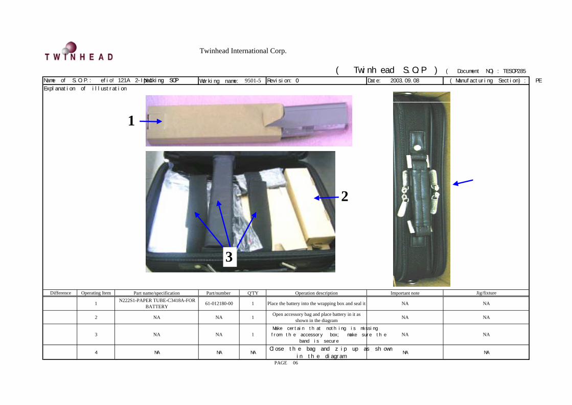
1 N222S1-PAPER TUBE-C3418A-FORBATTERY 61-012180-00 1 Place the battery into the wrapping box and seal it NA NA
2 NA NA 1 Open accessory bag and place battery in it asshown in the diagram NA NA
3 NA NA 1Make certain that nothing is missing
from the accessory box; make sure the
band is secure
NA NA
4 NA NA NAClose the bag and zip up as shown
in the diagramNA NA
PAGE: 06
( Twinhead S.O.P ) ( Document NO):TESOP285
Name of S.O.P.: efio!121A 2-IN-1 packing SOP
2
1
3
4
Twinhead International Corp.
Working name: 9501-6 Revision: 0 Date: 2003.09.08 (Manufacturing Section): PE
Explanation for illustration
Difference Operating Item Part name/specification Part/number Q'TY Operation description Important note Jig/fixture
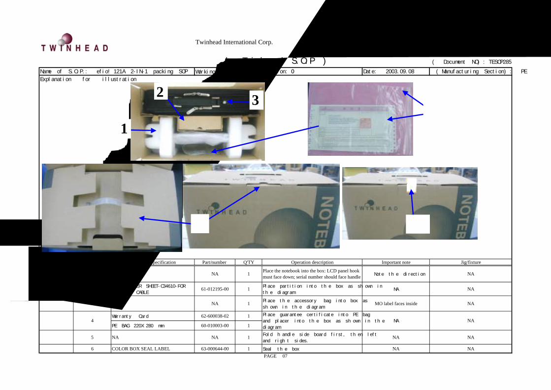
1 Notebook NA 1 Place the notebook into the box: LCD panel hookmust face down; serial number should face handle Note the direction NA
2 N222S1-PAPER SHEET-C34610-FOR
MOUSE & CABLE61-012195-00 1 Place partition into the box as shown in
the diagramNA NA
3附件包
NA 1 Place the accessory bag into box as
shown in the diagramMO label faces inside NA
Warranty Card 62-600038-02 1
PE BAG 220X280 mm 60-010003-00 1
5 NA NA 1 Fold handle side board first, then left
and right sides.NA NA
6 COLOR BOX SEAL LABEL 63-000644-00 1 Seal the box NA NAPAGE: 07
4 NA
( Twinhead S.O.P ) ( Document NO):TESOP285
Name of S.O.P.: efio!121A 2-IN-1 packing SOP
NA
Place guarantee certificate into PE bag
and placer into the box as shown in the
diagram
6
1
2 3
5
4

Twinhead International Corp.
Working name: 9501-7 Revision: 0 Date: 2003.09.08 (Manufacturing Section): PEExplanation of illustration
Difference Operating Item Part name/specification Part/number Q'TY Operation description Important note Jig/fixture1 P88TE-CARTON FOR W/CARRY BAG 61-050094-01 1 Assemble box NA NA
2 NA NA 2 Place the box into carton; gap faces gap. NA NA
3 Scotch tape 61-080007-01 1 Seal the box. 65cm~75cm NA NA
4 PACKING LABEL 63-001132-00 1 Place label as shown in the diagram
LABEL should be attached
ABOVE carton's part number
as shown above; do not cover
part the part number
NA
5 ALL MODULE PACKING 63-230XXX-00 2 Attach to the carton at an angleTake care not to damage
packingNA
6 ANGEL PROTECTOR 76X76X800mm 61-097608-00 1 NA NA NA7 ANGEL PROTECTOR 76X76X1040mm 61-097615-00 1 NA NA NA8 PALLET FOR SHARP AV-1 KL13020 61-110010-00 1 NA NA NA
PAGE: 08
( Twinhead S.O.P ) ( Document NO): TESOP285
Name of S.O.P.: efio!121A 2-IN-1 Packing SOP
45
1 3
2