TM 5-2420-224-20-1 Volume No. 1 TECHNICAL MANUAL UNIT MAINTENANCE MANUAL FOR TRACTOR, WHEELED, 4 X 4 DED SMALL EMPLACEMENT EXCAVATOR (SEE) (NSN 2420-01-160-2754) (EIC:EDL) TRACTOR, WHEELED, 4 X 4 DED TABLE OF CONTENTS i HOW TO USE THIS MANUAL xii PREVENTIVE MAINTENANCE 2-2 CHECKS AND SERVICES HIGH MOBILITY MATERIAL HANDLER (HMMH) (NSN 2420-01-205-8636) INDEX Index-1 HEADQUARTERS, DEPARTMENT OF THE ARMY 28 JULY 1993 This manual along with TM5-2420-224-20-2 and TM5-2420-224-34 supersedes TM5–2420–224-24 dated December 1989 Approved for public release; distribution is unlimited.
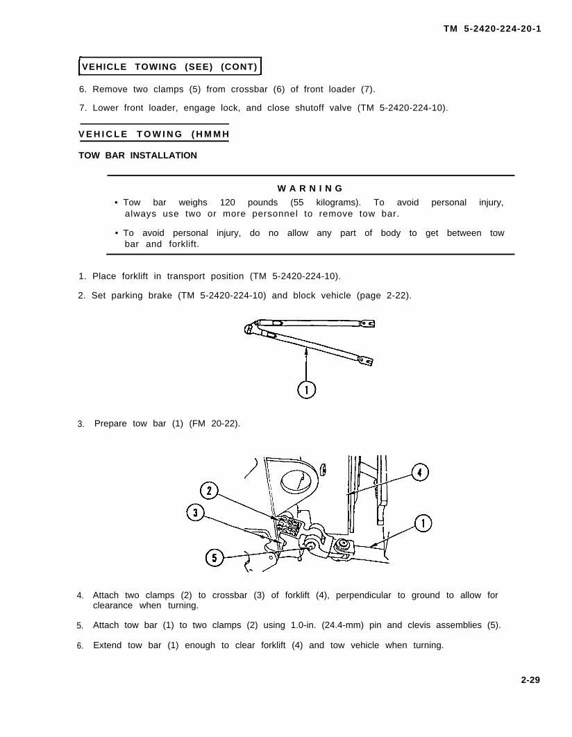
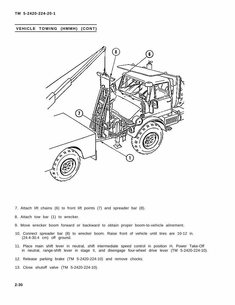
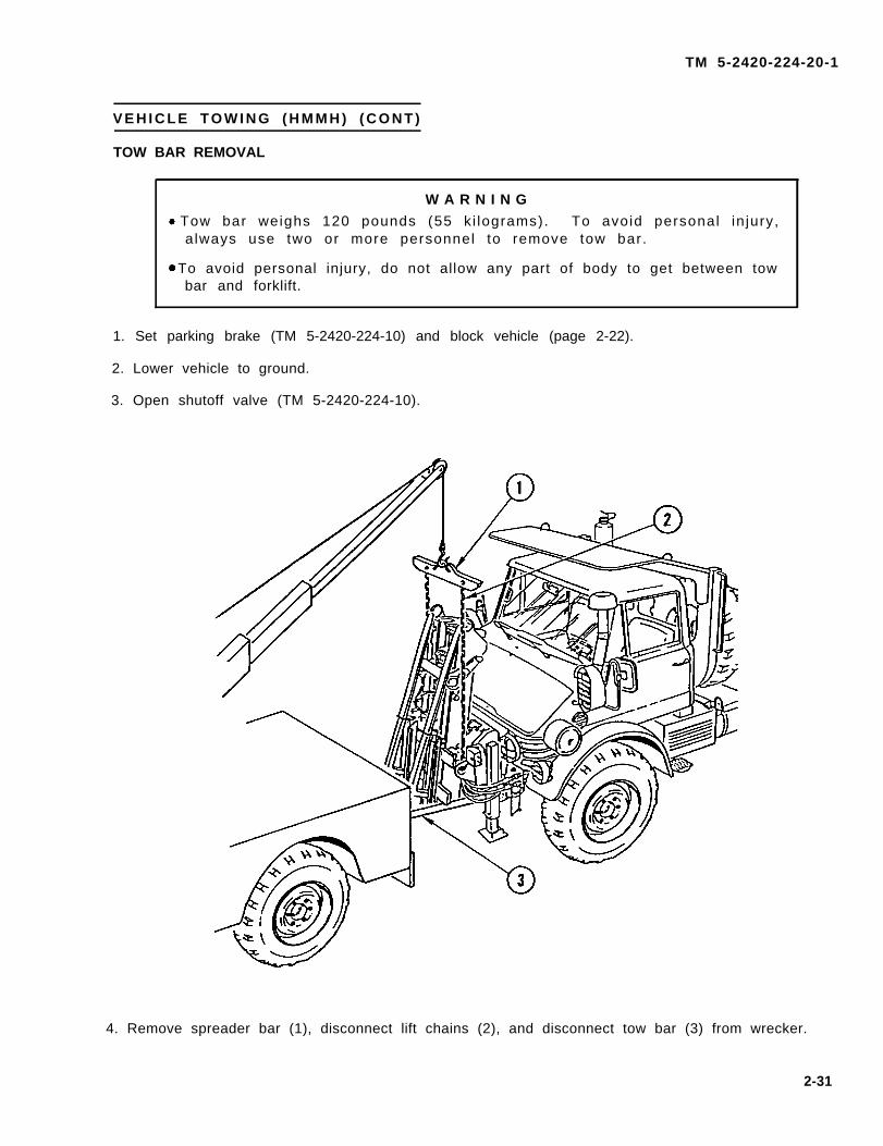
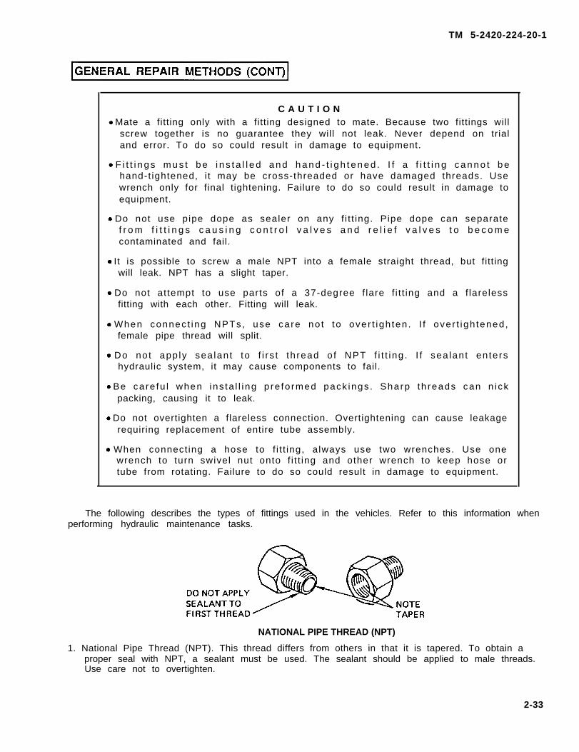
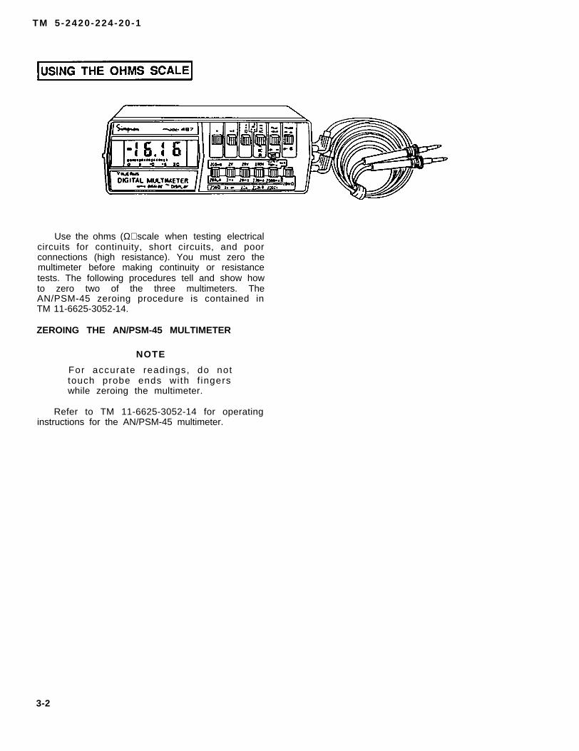
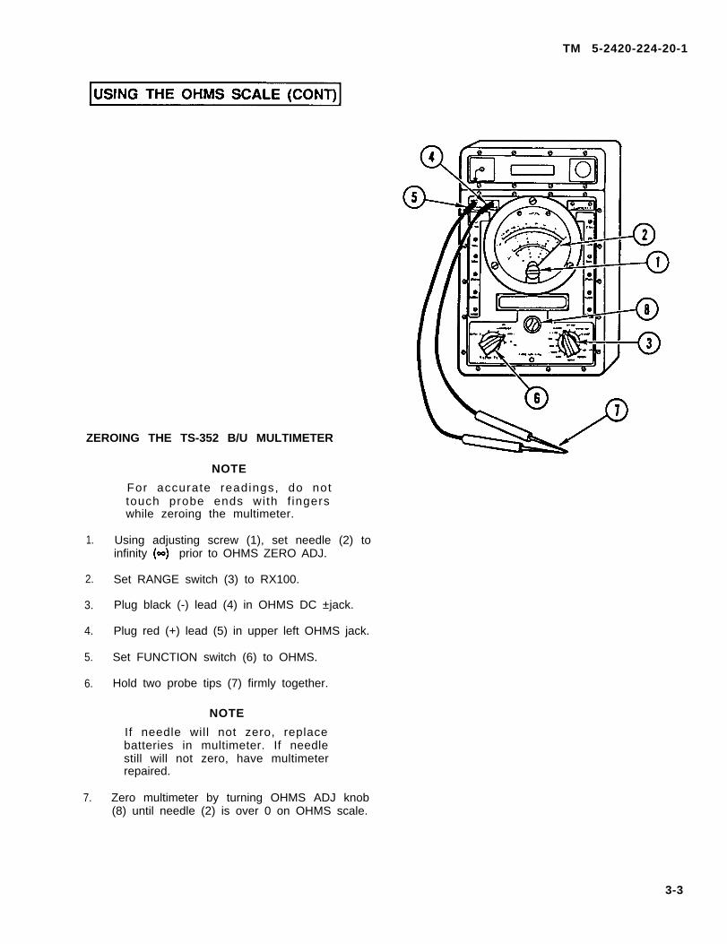
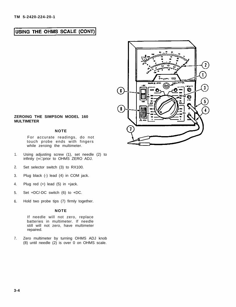
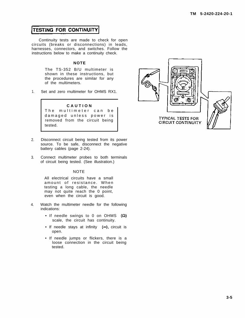
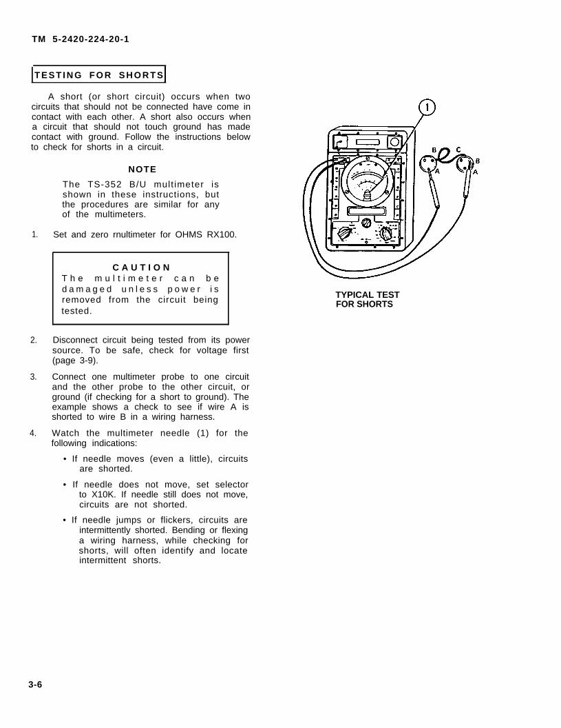
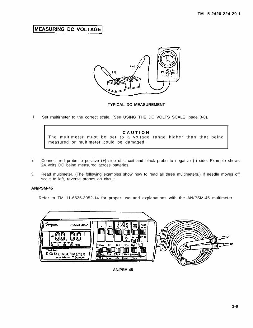
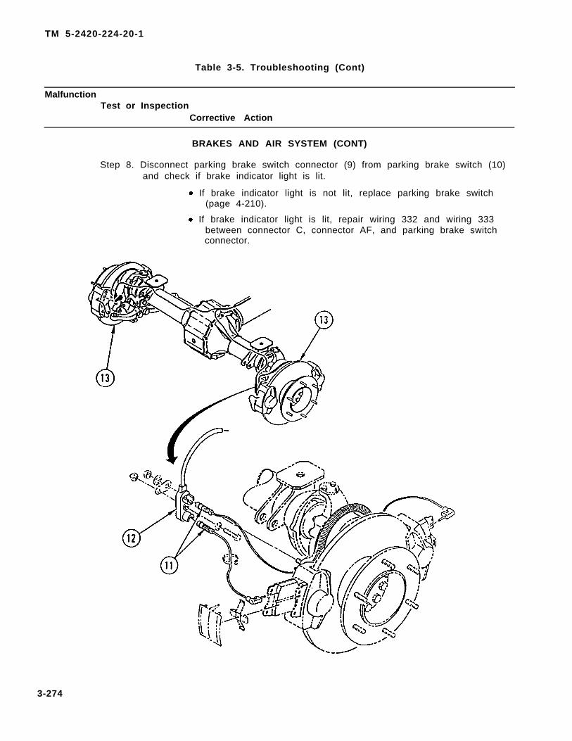
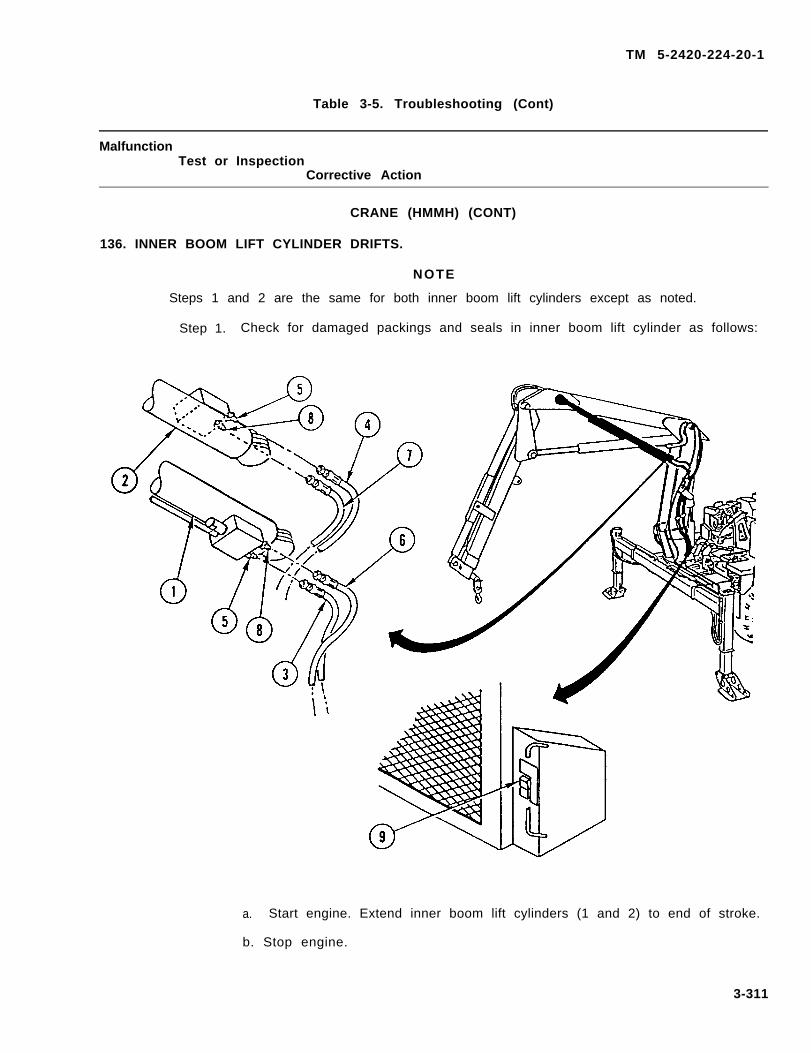
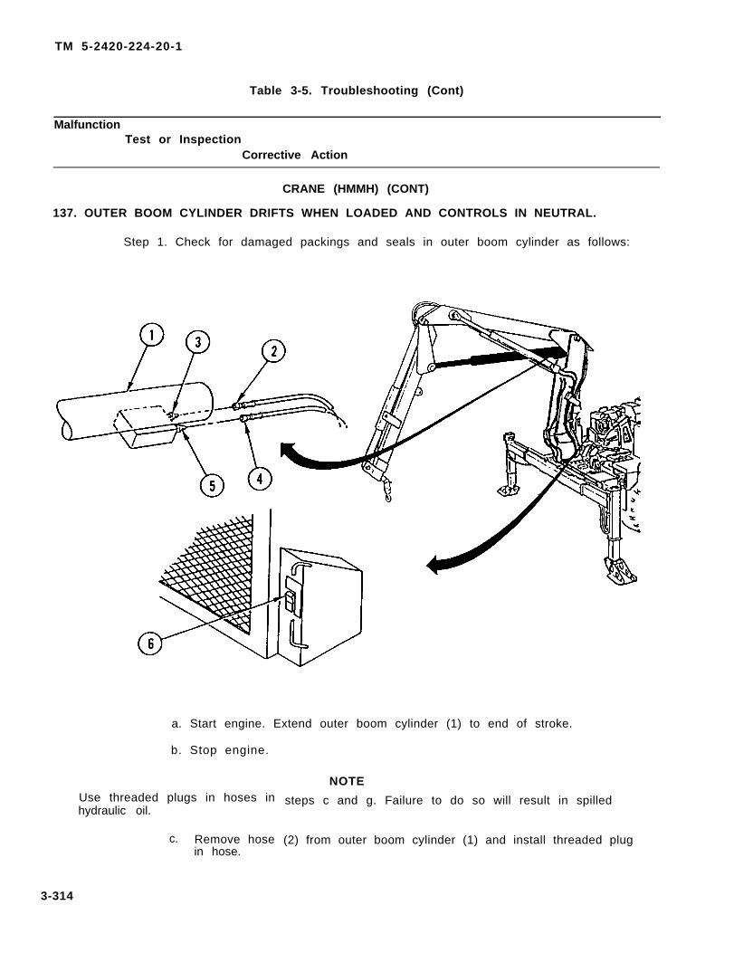
Transcript
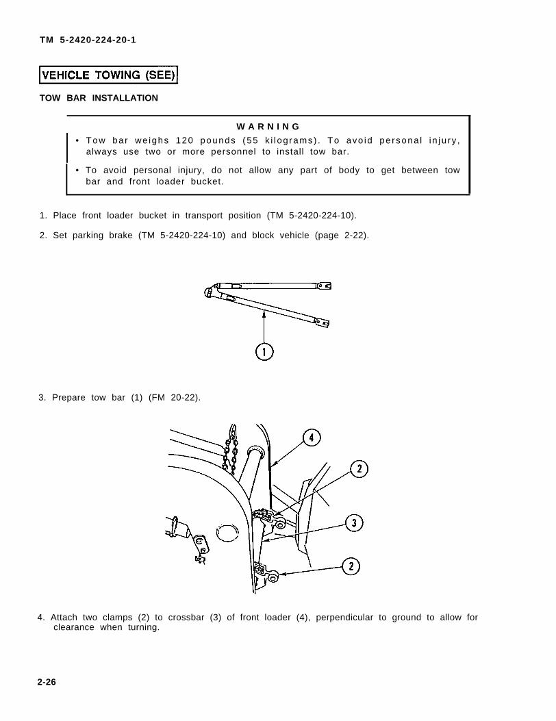
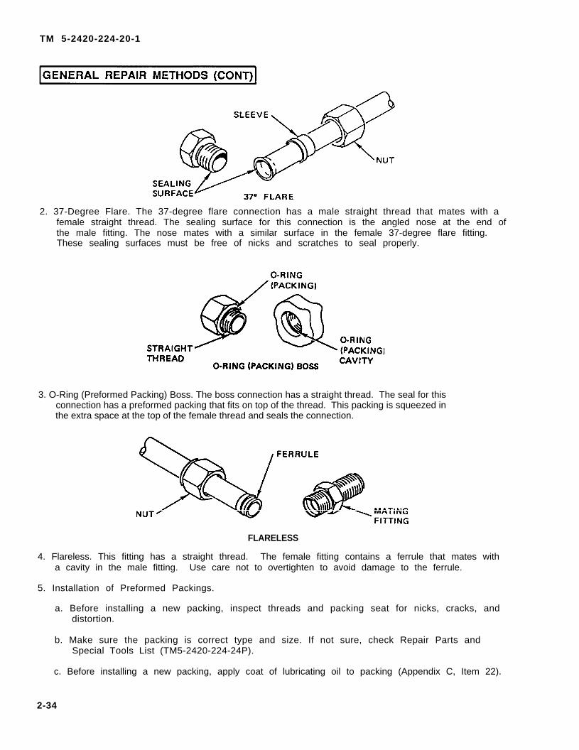
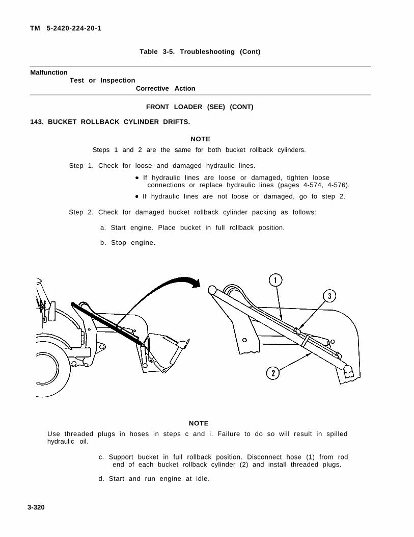
TM 5-2420-224-20-1Volume No. 1
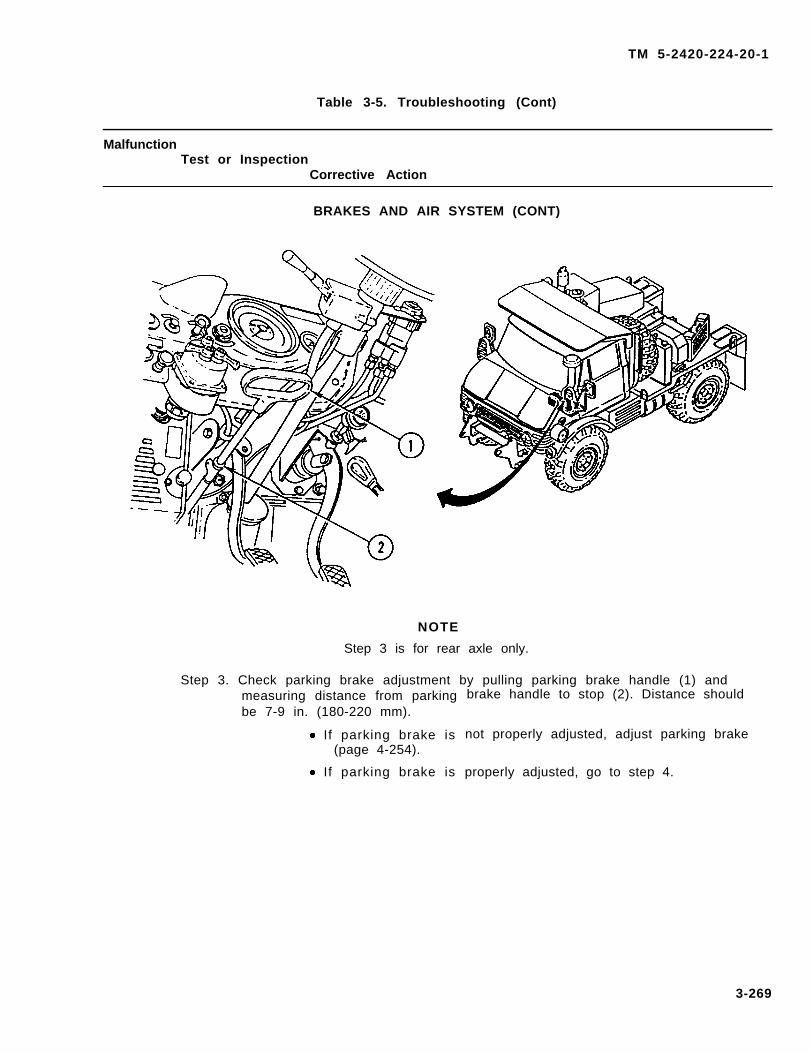
TECHNICAL MANUAL
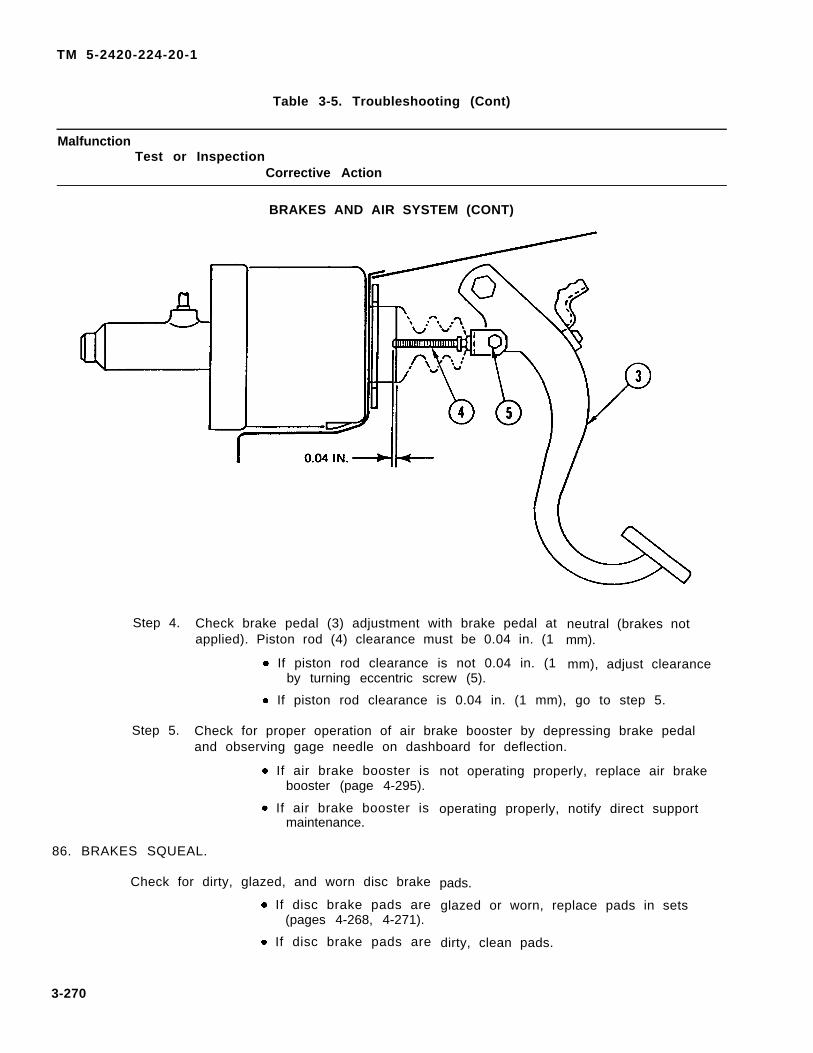
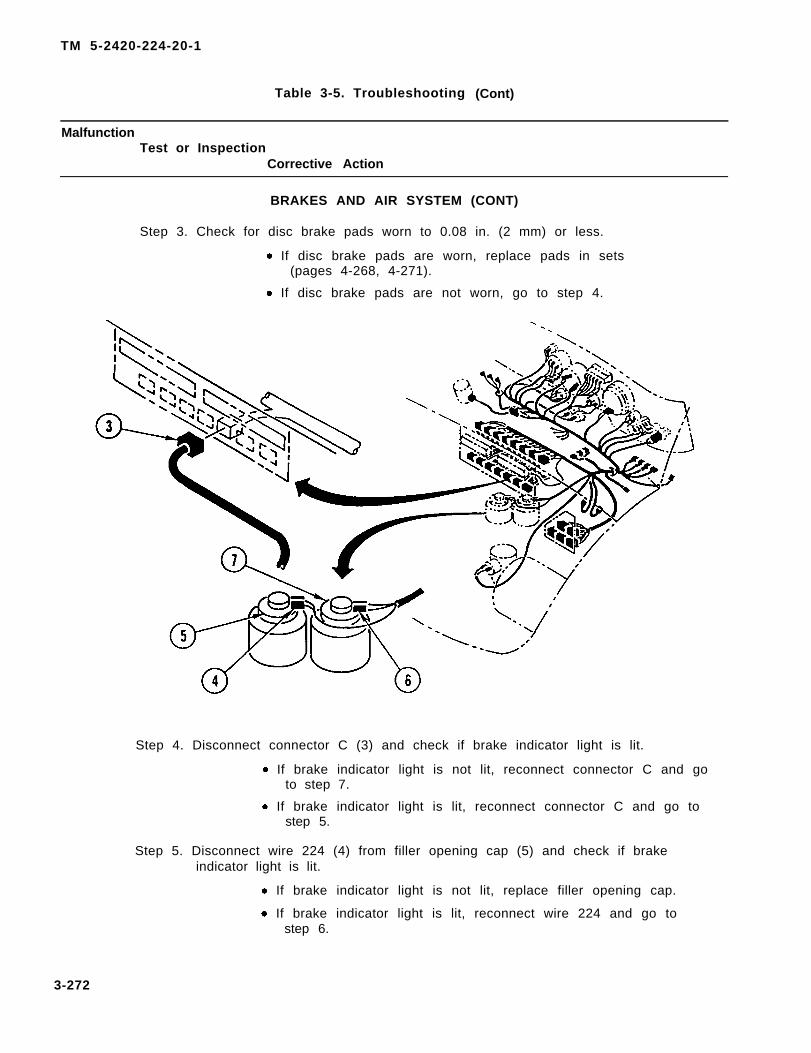
UNIT MAINTENANCE MANUALFOR
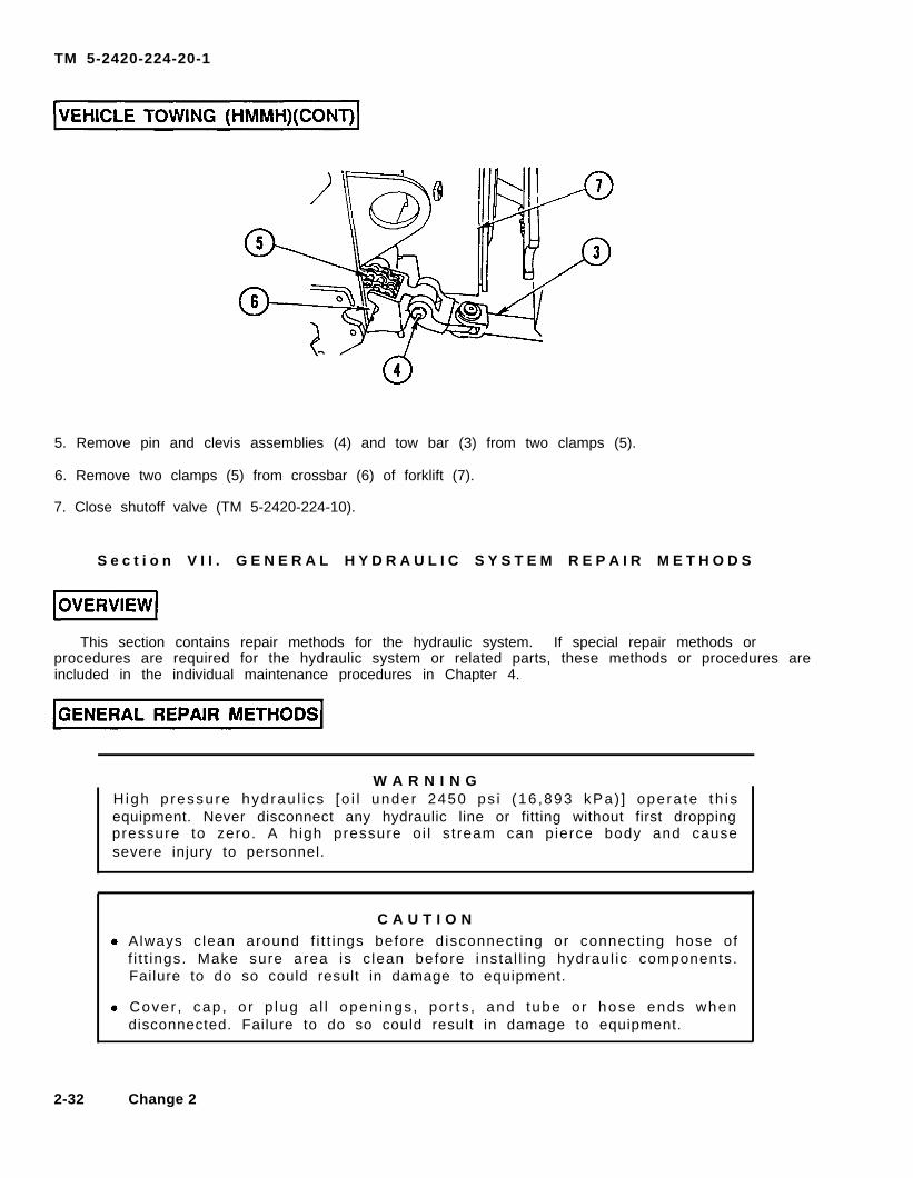
TRACTOR, WHEELED, 4 X 4 DEDSMALL EMPLACEMENT EXCAVATOR (SEE)
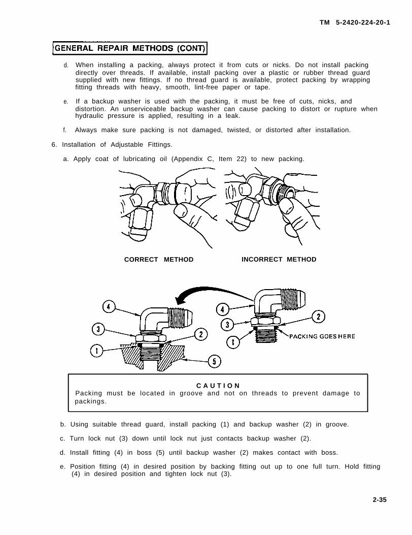
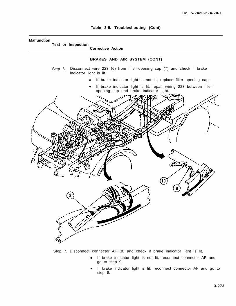
( N S N 2 4 2 0 - 0 1 - 1 6 0 - 2 7 5 4 ) ( E I C : E D L )
TRACTOR, WHEELED, 4 X 4 DED
TABLE OF CONTENTS i
HOW TO USE THISMANUAL
xii
PREVENTIVEMAINTENANCE 2-2CHECKS AND SERVICES
HIGH MOBILITY MATERIAL HANDLER (HMMH)(NSN 2420-01-205-8636)
INDEX Index-1
HEADQUARTERS, DEPARTMENT OF THE ARMY 28 JULY 1993This manual along with TM5-2420-224-20-2 and TM5-2420-224-34 supersedes
TM5–2420–224-24 dated December 1989Approved for public release; distribution is unlimited.
TM 5-2420-224-20-1
W A R N I N G
CARBON MONOXIDE POISONING CAN BE DEADLY
CARBON MONOXIDE IS A COLORLESS, ODORLESS, DEADLY POISONOUSGAS, WHICH, WHEN BREATHED, DEPRIVES THE BODY OF OXYGEN ANDCAUSES SUFFOCATION. EXPOSURE TO AIR CONTAMINATED WITH CARBONMONOXIDE PRODUCES SYMPTOMS OF HEADACHE, DIZZINESS, LOSS OFMUSCULAR CONTROL, APPARENT DROWSINESS, OR COMA. PERMANENTBRAIN DAMAGE OR DEATH CAN RESULT FROM SEVERE EXPOSURE.
CARBON MONOXIDE OCCURS IN THE EXHAUST FUMES OF FUEL-BURNINGH E A T E R S A N D I N T E R N A L - C O M B U S T I O N E N G I N E S A N D B E C O M E SD A N G E R O U S L Y C O N C E N T R A T E D U N D E R C O N D I T I O N S O F I N A D E Q U A T EVENTILATION. THE FOLLOWING PRECAUTIONS MUST BE OBSERVED TOE N S U R E T H E S A F E T Y O F P E R S O N N E L W H E N E V E R T H E P E R S O N N E LHEATER, MAIN, OR AUXILIARY ENGINE OF ANY VEHICLE IS OPERATED FORMAINTENANCE PURPOSES OR TACTICAL USE:
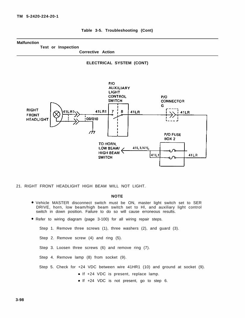
1.
2.
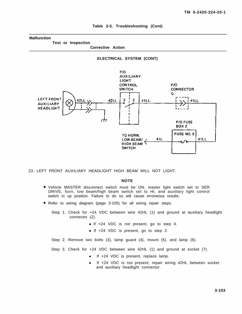
3.
4.
DO NOT operate engine of vehicle in an enclosed area unless it isADEQUATELY VENTILATED.
DO NOT idle engine for long periods without maintaining ADEQUATEVENTILATION in the personnel compartments.
DO NOT drive any vehicle with inspection plates, cover plates, or enginecompartment doors removed unless necessary for maintenance purposes.
BE ALERT. at all times during vehicle operation for exhaust odors andexposure symptoms. If either is present, IMMEDIATELY VENTILATEpersonnel compartments. If symptoms persist, remove affected personnelfrom vehicle and treat as follows: expose to fresh air; keep warm, DONOT PERMIT EXERCISE; if necessary, administer artificial respiration(see FM 21-11).
T H E B E S T D E F E N S E A G A I N S T C A R B O N M O N O X I D E P O I S O N I N G I SADEQUATE VENTILATION.
a
TM 5-2420-224-20-1
W A R N I N G
COMPRESSED AIR
To prevent injury, compressed air used for cleaning and drying purposes will notexceed 30 psi (207 kPa). Use only wi th ef fect ive chip guarding and personalprotective equipment (goggles/shield, gloves, etc.).
W A R N I N G
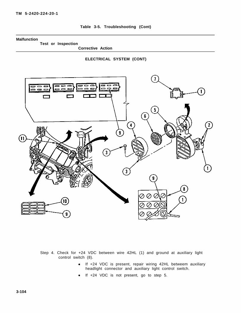
Drycleaning solvent P-D-680 is toxic and flammable. Wear protective goggles andgloves and use only in well-ventilated area. Avoid contact with skin, eyes, andclothes and do not breathe vapors. Do not use near open f lame or excessiveheat. Flash point is 100°-138° F (38°-50°C). I f you become dizzy whi le usingdrycleaning solvent, get fresh air immediately and get medical aid. If contact witheyes is made, wash your eyes with water and get medical aid immediately.
W A R N I N G
Remove r ings , b race le ts , wr i s twa tches , and neck cha ins be fo re work ing onvehicle. Jewelry can catch on equipment and cause injury, or may short acrossan electrical circuit and cause severe burns or electrical shock.
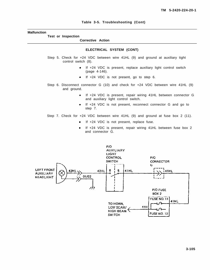
W A R N I N G
Diese l fue l i s f l ammab le . Do no t per fo rm th is p rocedure near f i re , f l ame, o rsparks. Injury or death to personnel could result.
W A R N I N G
Do not connect or d isconnect any electr ical connector unless vehic le MASTERdisconnect switch is OFF. To do so could result in injury to personnel.
W A R N I N G
Do not disconnect any air system lines or fitt ings unless vehicle engine is shuto f f and a i r sys tem pressure i s re l i eved . To do so cou ld resu l t i n in ju ry topersonnel.
b
TM 5-2420-224-20-1
W A R N I N G
All vehicle electrical switches must be OFF before disconnecting battery cables.Failure to do so could result in injury to personnel.
W A R N I N G
H i g h p r e s s u r e h y d r a u l i c s [ o i l u n d e r 2 4 5 0 p s i ( 1 6 , 8 9 3 k P a ) ] o p e r a t e t h i sequipment. Never disconnect any hydraul ic l ine or f i t t ing without f i rst droppingpressure to zero. A high pressure oil stream can pierce body and cause severeinjury to personnel.
If NBC exposure is suspected, all air filter media should be handled by personnelwearing protective equipment. Consult your unit NBC Officer or NBC NCO for
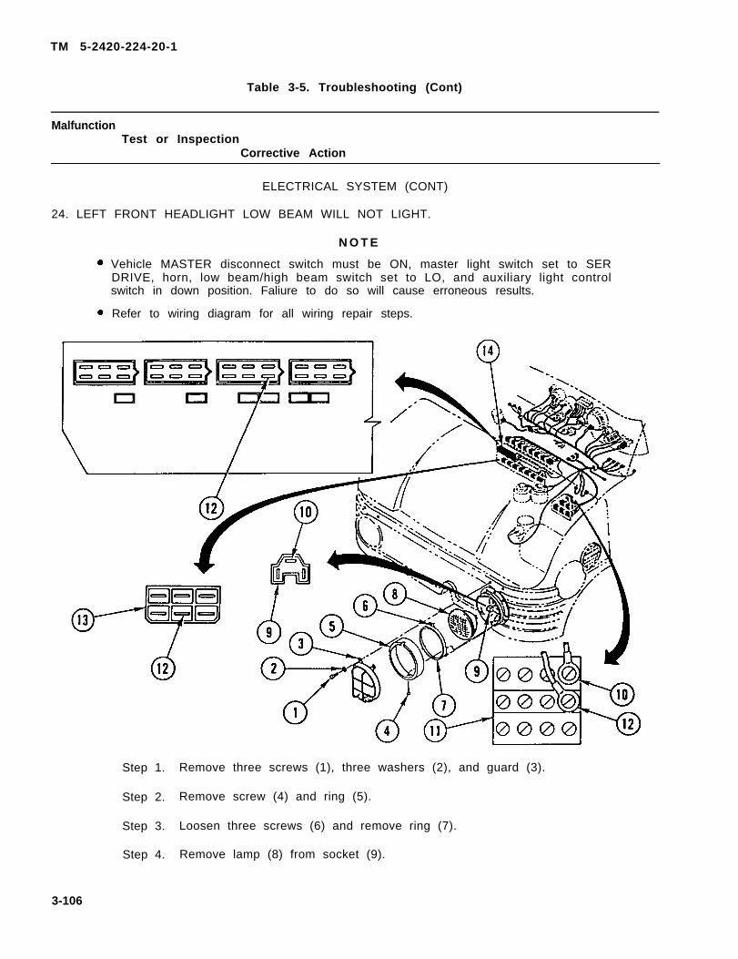
W A R N I N G
appropriate handling or disposal instructions.
W A R N I N G
Never use gasoline to clean parts. Gasoline is highly flammable. Serious personalinjury could - result if fuel ignites during cleaning.
W A R N I N G
Prior to initial use, new, extensively repaired, or altered forklift or crane must beload tested to prevent injury to personnel.
Steam cleaning creates hazardous noise levels and severe burn potential. Eye,skin, and ear protection are required.
W A R N I N G
W A R N I N G
Solvents used with spray gun must be used in spray booth with filter. Face shieldmust be used by personnel operating spray gun. Failure to do so could result inserious injury to personnel.
c
TM 5-2420-224-20-1
W A R N I N G
Dri l l ing and gr inding operat ions are hazardous to the eyes. Eye protect ion isrequired.
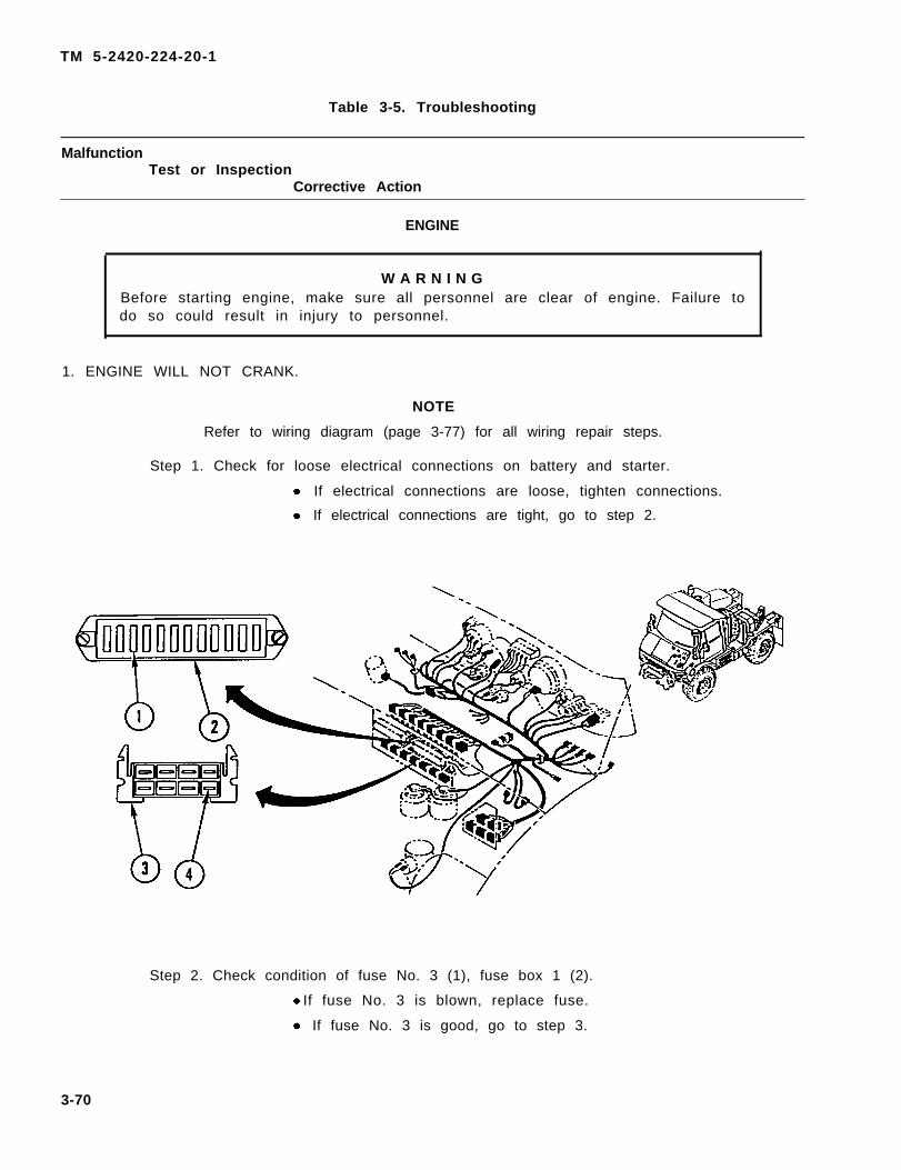
Before starting engine, make sure all personnel are clear of engine. Failure to doso could result in injury to personnel.
W A R N I N G
On direct contact, uncured silicone sealant irritates eyes. In case of contact, flusheyes with water and seek medical attention. Avoid prolonged contact with skin.
W A R N I N G
W A R N I N G
When replacing fuses, make sure only fuses of correct amperage are installed.Failure to do so could result in injury to personnel or damage to equipment.
d/(e Blank)
TM 5-2420-224-20-1 C2
CHANGE HEADQUARTERS
DEPARTMENT OF THE ARMY NO. 2 Washington, D.C., 30 March 2004
UNIT MAINTENANCE MANUAL FOR
TRACTOR, WHEELED, 4 X 4 DED SMALL EMPLACEMENT EXCAVATOR (SEE)
(NSN 2420-01-160-2754) (EIC:EDL)
AND
TRACTOR, WHEELED, 4 X 4 DED HIGH MOBILITY MATERIAL HANDLER (HMMH)
(NSN 2420-01-205-8636) TM 5-2420-224-20-1, dated 28 July 1993, is updated as follows: 1. File this sheet in front of the manual for reference. 2. New or changed material is indicated by a vertical bar adjacent to the material and/or change designators at
bottom of affected page. 3. New or changed illustrations are indicated by a miniature pointing hand adjacent to the updated area. 4. Remove old pages and insert new pages as indicated below.
Remove Pages Insert Pages A/(B Blank) A and B i and ii i and ii xi and xii xi and xii 1-9 and 1-10 1-9 and 1-10 2-1 through 2-4 2-1 through 2-4 2-9 through 2-14 2-9 through 2-14 None 2-14.1 through 2-14.24 2-15 and 2-16 2-15 and 2-16 2-21 and 2-22 2-21 and 2-22 2-31 and 2-32 2-31 and 2-32 2-35 through 2-38 2-35 through 2-38 3-63 and 3-64 3-63 and 3-64 3-83 and 3-84 3-83 and 3-84 3-265 through 3-268 3-265 through 3-268 3-271 and 3-272 3-271 and 3-272 3-277 through 3-286 3-277 through 3-286 3-293 through 3-298 3-293 through 3-298 3-309 and 3-310 3-309 and 3-310 Index-9 through Index-12 Index-9 through Index-12
TM 5-2420-224-20-1
By Order of the Secretary of the Army:
PETER J. SCHOOMAKER
General, United States Army
Chief of Staff
Official:
JOEL B. HUDSON
Administrative Assistant to the
Secretary of the Army
0406802
DISTRIBUTION:
To be distributed in accordance with the Initial Distribution Number (IDN) 380973 requirements for TM 5-2420-224-20-1.
TM 5-2420-224-20-1
CHANGE HEADQUARTERS
DEPARTMENT OF THE ARMY NO. 1 Washington, D.C., 7 October 2003
UNIT MAINTENANCE MANUAL FOR
TRACTOR, WHEELED, 4 X 4 DED SMALL EMPLACEMENT EXCAVATOR (SEE)
(NSN 2420-01-160-2754) (EIC:EDL)
AND
TRACTOR, WHEELED, 4 X 4 DED HIGH MOBILITY MATERIAL HANDLER (HMMH)
(NSN 2420-01-205-8636) TM 5-2420-224-20-1, dated 28 July 1993, is updated as follows: 1. File this sheet in front of the manual for reference. 2. New or changed material is indicated by a vertical bar adjacent to the material and/or change designators at
bottom of affected page. 3. New or changed illustrations are indicated by a miniature pointing hand adjacent to the updated area. 4. Remove old pages and insert new pages as indicated below.
Remove Pages Insert Pages None A/(B Blank) iii and iv iii and iv vii and viii vii and viii 1-1 and 1-2 1-1 and 1-2 None 1-16.1 through 1-16.22 2-5 through 2-12 2-5 through 2-12 3-31 through 3-34 3-31 through 3-34 3-63 through 3-66 3-63 through 3-66 3-135 and 3-136 3-135 and 3-136 3-149 and 3-150 3-149 and 3-150 3-215 and 3-216 3-215 and 3-216 3-267 and 3-268 3-267 and 3-268 None 3-268.1 and 3-268.2 Index-1 and Index-2 Index-1 and Index-2 Index-5 and Index-6 Index-5 and Index-6 Index-11 through Index-14 Index-11 through Index-14 Index-17/(Index-18 Blank) Index-17/(Index-18 Blank) DA Form 2028-2 DA Form 2028
TM 5-2420-224-20-1
By Order of the Secretary of the Army:
PETER J. SCHOOMAKER
General, United States Army
Chief of Staff
Official:
JOEL B. HUDSON
Administrative Assistant to the
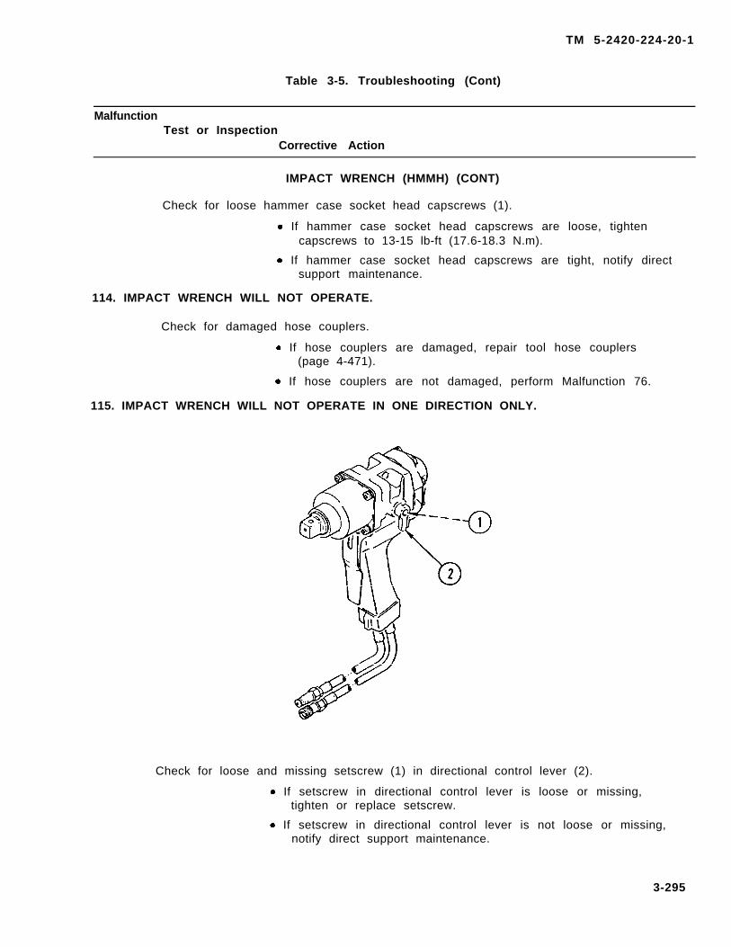
Secretary of the Army 0222001
DISTRIBUTION:
To be distributed in accordance with the Initial Distribution Number (IDN) 380973 requirements for TM 5-2420-224-20-1.
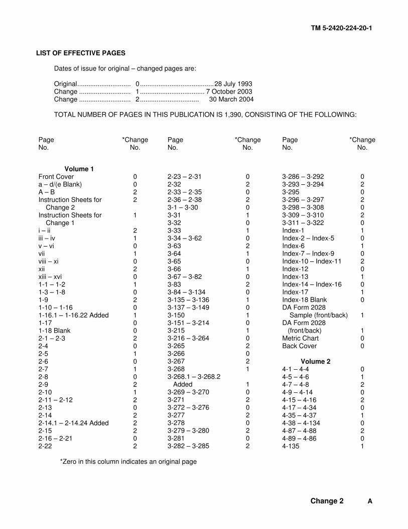
TM 5-2420-224-20-1
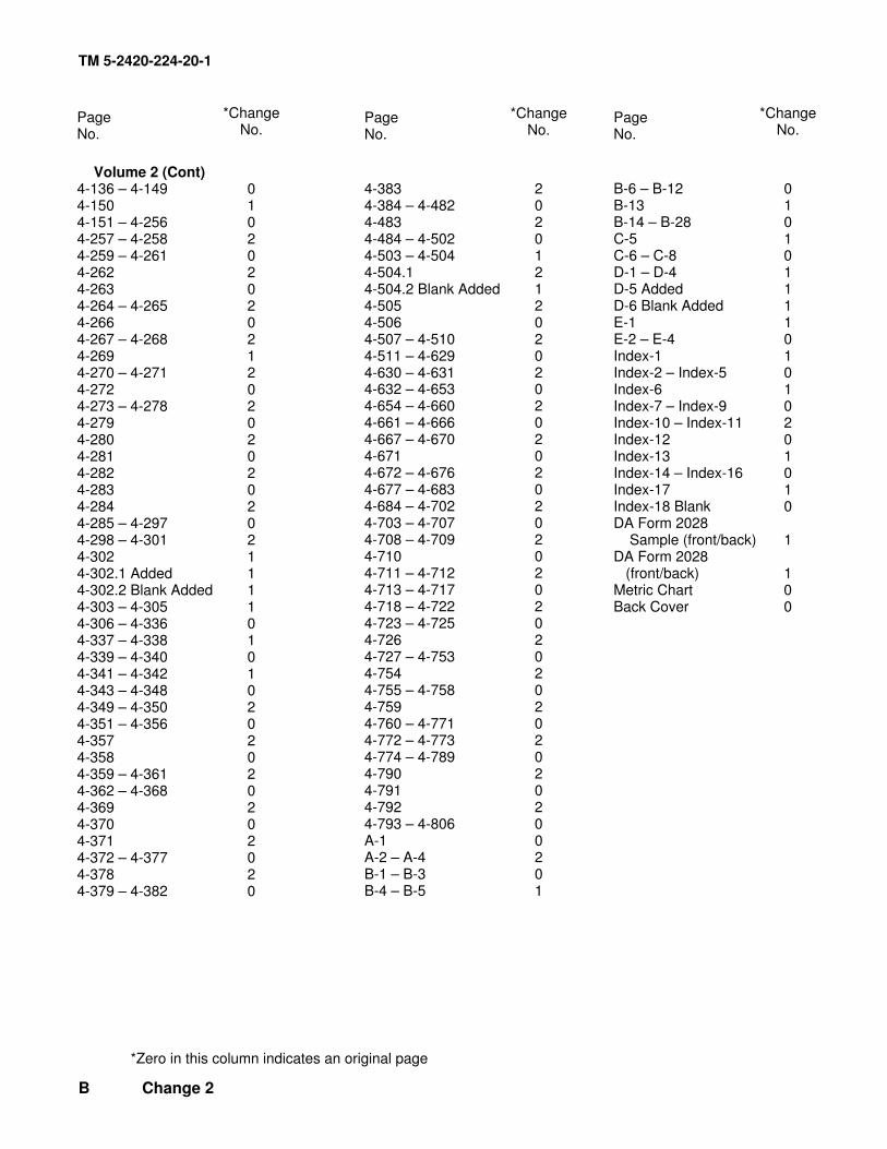
LIST OF EFFECTIVE PAGES Dates of issue for original – changed pages are: Original............................. 0........................................28 July 1993 Change ............................ 1................................... 7 October 2003 Change ............................ 2................................ 30 March 2004 TOTAL NUMBER OF PAGES IN THIS PUBLICATION IS 1,390, CONSISTING OF THE FOLLOWING:
Page No.
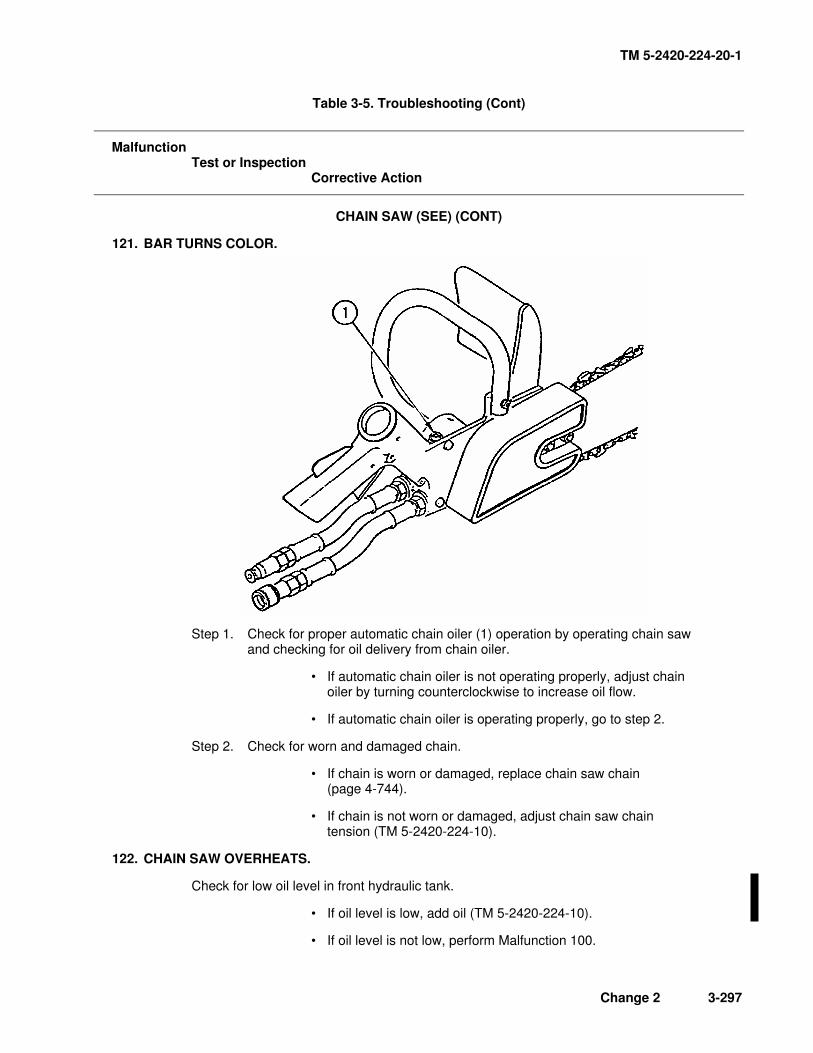
*Change No.
Volume 1 Front Cover 0 a – d/(e Blank) 0 A – B 2 Instruction Sheets for Change 2
2
Instruction Sheets for Change 1
1
i – ii 2 iii – iv 1 v – vi 0 vii 1 viii – xi 0 xii 2 xiii – xvi 0 1-1 – 1-2 1 1-3 – 1-8 0 1-9 2 1-10 – 1-16 0 1-16.1 – 1-16.22 Added 1 1-17 0 1-18 Blank 0 2-1 – 2-3 2 2-4 0 2-5 1 2-6 0 2-7 1 2-8 0 2-9 2 2-10 1 2-11 – 2-12 2 2-13 0 2-14 2 2-14.1 – 2-14.24 Added 2 2-15 2 2-16 – 2-21 0 2-22 2
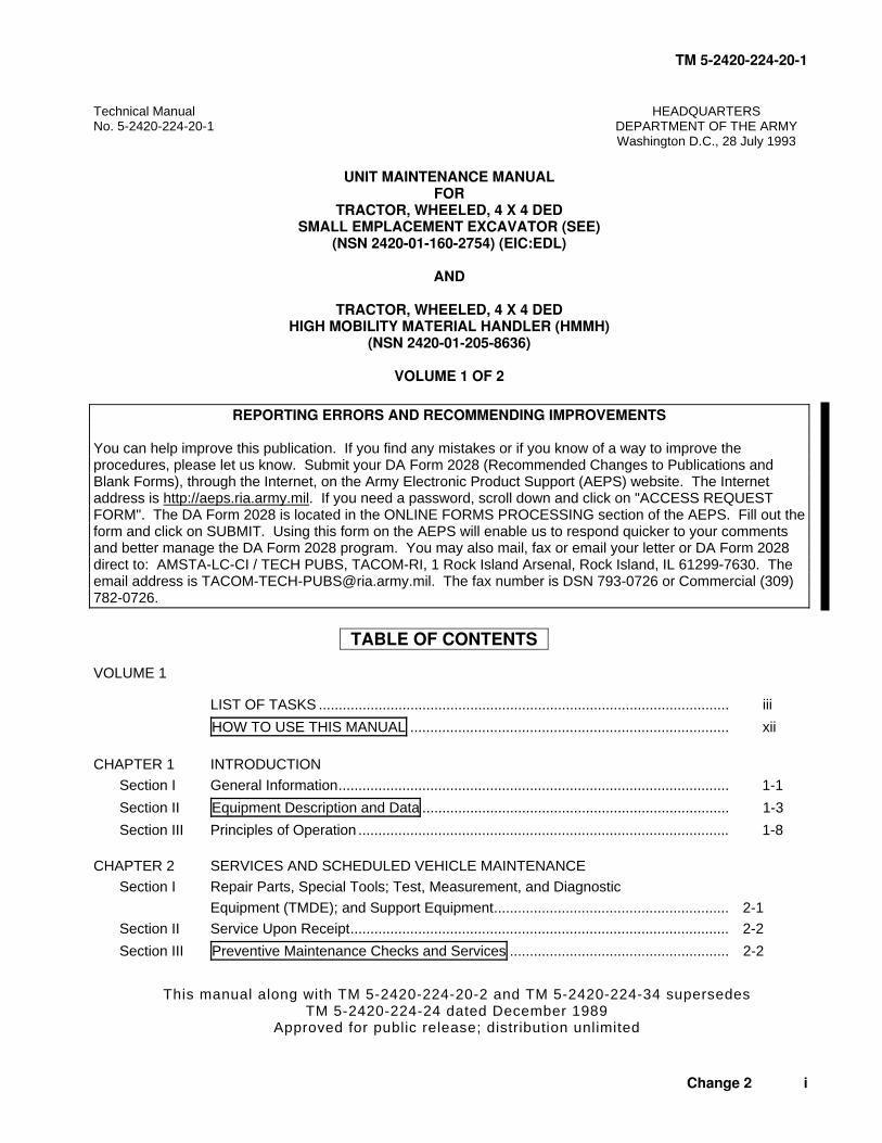
Technical Manual HEADQUARTERS No. 5-2420-224-20-1 DEPARTMENT OF THE ARMY Washington D.C., 28 July 1993
UNIT MAINTENANCE MANUAL
FOR TRACTOR, WHEELED, 4 X 4 DED
SMALL EMPLACEMENT EXCAVATOR (SEE) (NSN 2420-01-160-2754) (EIC:EDL)
AND
TRACTOR, WHEELED, 4 X 4 DED
HIGH MOBILITY MATERIAL HANDLER (HMMH) (NSN 2420-01-205-8636)
VOLUME 1 OF 2
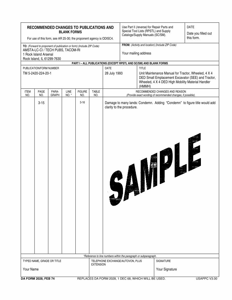
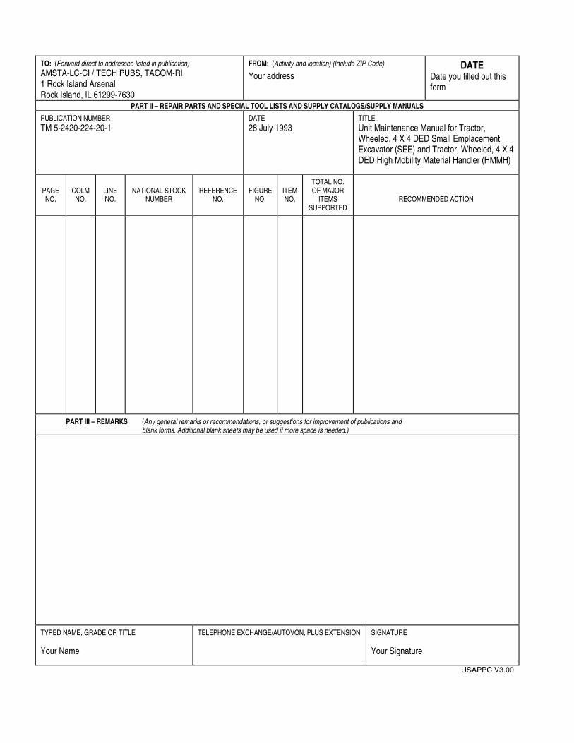
REPORTING ERRORS AND RECOMMENDING IMPROVEMENTS
You can help improve this publication. If you find any mistakes or if you know of a way to improve the procedures, please let us know. Submit your DA Form 2028 (Recommended Changes to Publications and Blank Forms), through the Internet, on the Army Electronic Product Support (AEPS) website. The Internet address is http://aeps.ria.army.mil. If you need a password, scroll down and click on "ACCESS REQUEST FORM". The DA Form 2028 is located in the ONLINE FORMS PROCESSING section of the AEPS. Fill out the form and click on SUBMIT. Using this form on the AEPS will enable us to respond quicker to your comments and better manage the DA Form 2028 program. You may also mail, fax or email your letter or DA Form 2028 direct to: AMSTA-LC-CI / TECH PUBS, TACOM-RI, 1 Rock Island Arsenal, Rock Island, IL 61299-7630. The email address is [email protected]. The fax number is DSN 793-0726 or Commercial (309) 782-0726.
TABLE OF CONTENTS
VOLUME 1 LIST OF TASKS ....................................................................................................... iii
HOW TO USE THIS MANUAL ................................................................................ xii
CHAPTER 1 INTRODUCTION
Section I General Information.................................................................................................. 1-1
Section II Equipment Description and Data ............................................................................. 1-3
Section III Principles of Operation ............................................................................................. 1-8 CHAPTER 2 SERVICES AND SCHEDULED VEHICLE MAINTENANCE
Section I Repair Parts, Special Tools; Test, Measurement, and Diagnostic
Equipment (TMDE); and Support Equipment........................................................... 2-1
Section II Service Upon Receipt............................................................................................... 2-2
Section III Preventive Maintenance Checks and Services ....................................................... 2-2
This manual along with TM 5-2420-224-20-2 and TM 5-2420-224-34 supersedes TM 5-2420-224-24 dated December 1989
Approved for public release; distribution unlimited
Change 2 i
TM 5-2420-224-20-1
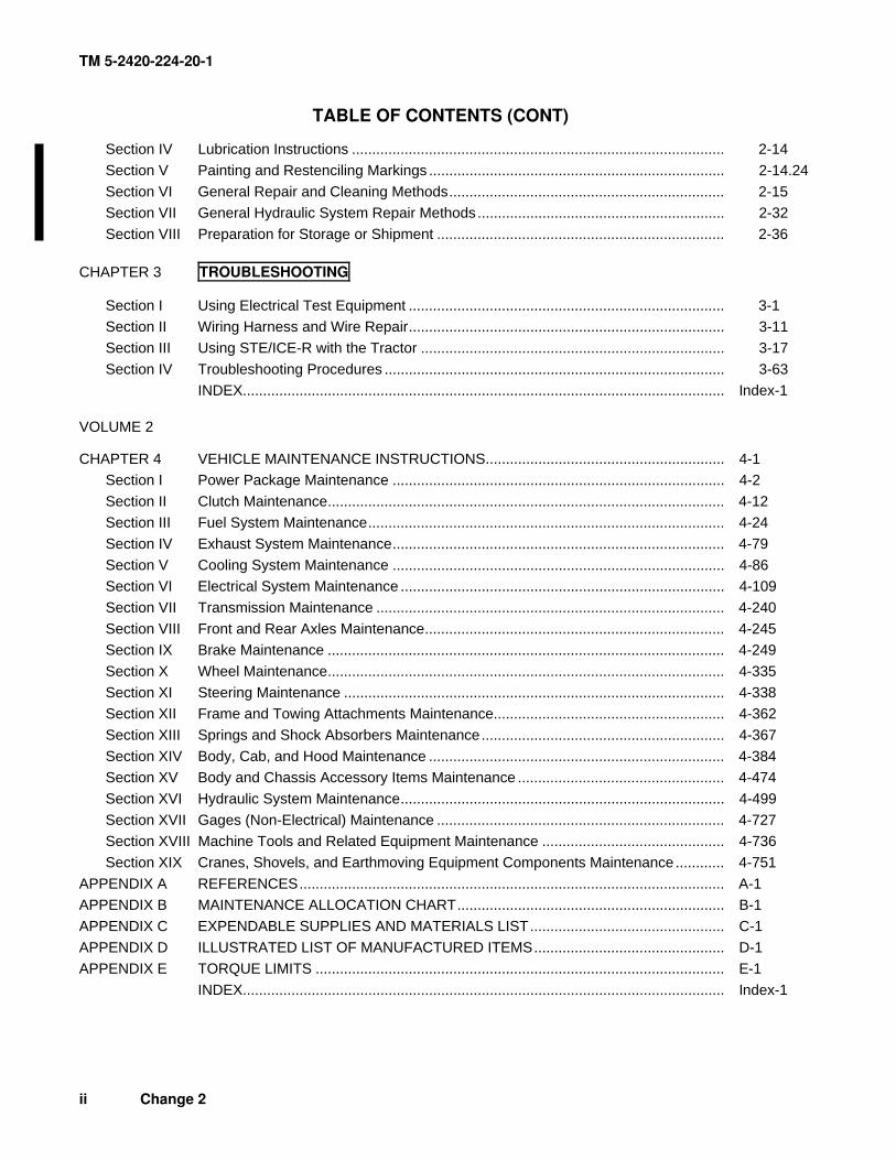
TABLE OF CONTENTS (CONT)
Section IV Lubrication Instructions ............................................................................................ 2-14
Section V Painting and Restenciling Markings ......................................................................... 2-14.24
Section VI General Repair and Cleaning Methods.................................................................... 2-15 Section VII General Hydraulic System Repair Methods............................................................. 2-32
Section VIII Preparation for Storage or Shipment ....................................................................... 2-36 CHAPTER 3 TROUBLESHOOTING
Section I Using Electrical Test Equipment .............................................................................. 3-1 Section II Wiring Harness and Wire Repair.............................................................................. 3-11
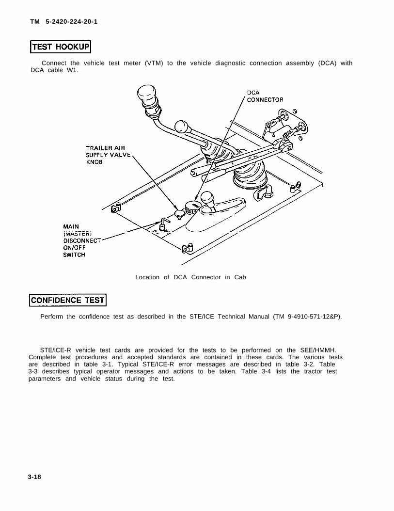
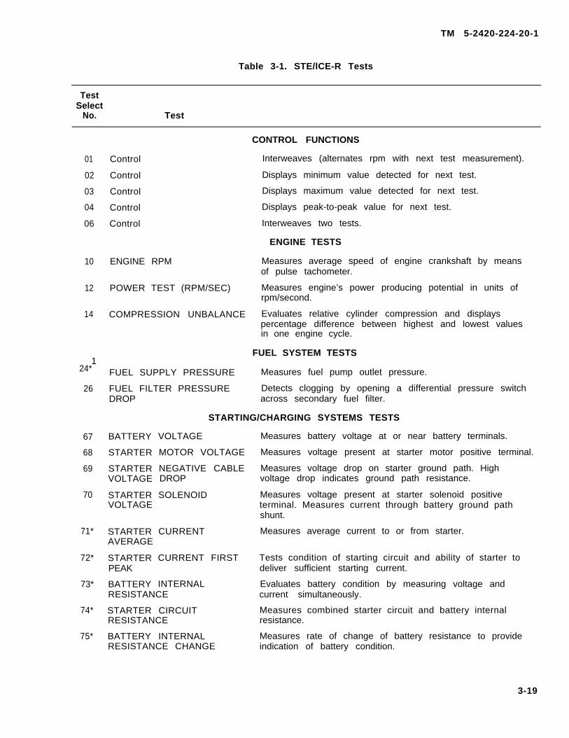
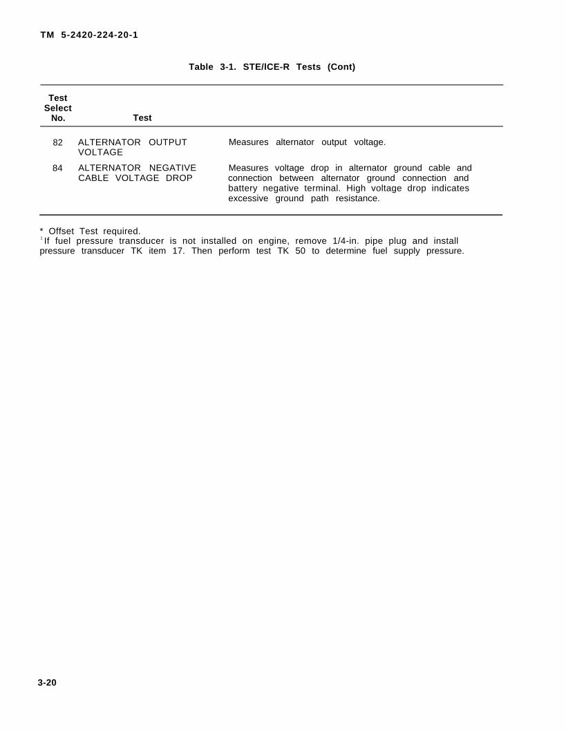
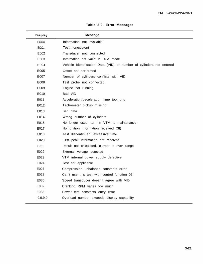
Section III Using STE/ICE-R with the Tractor ........................................................................... 3-17
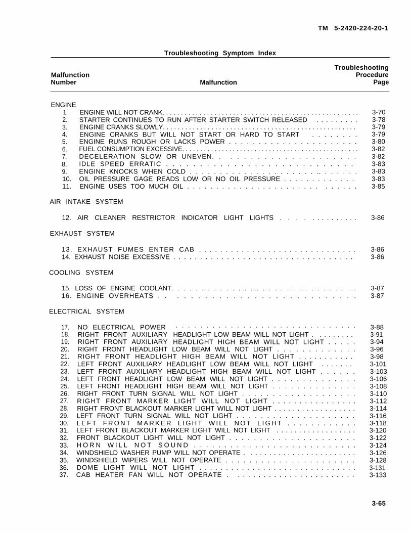
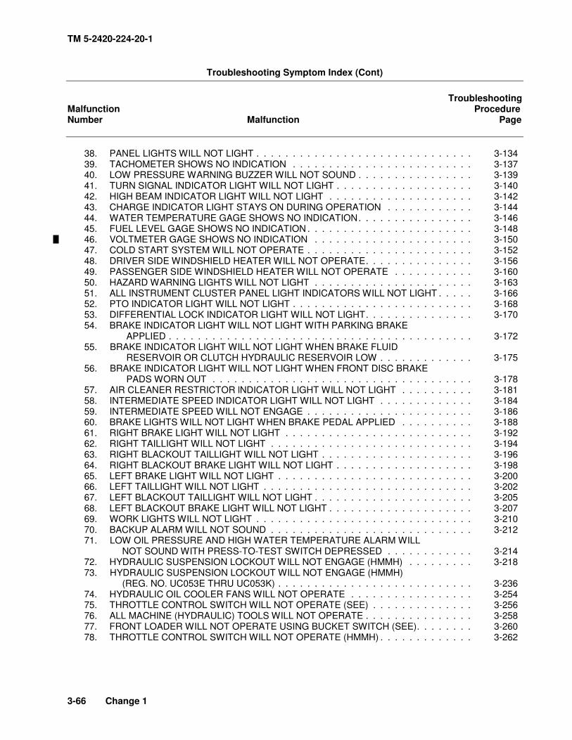
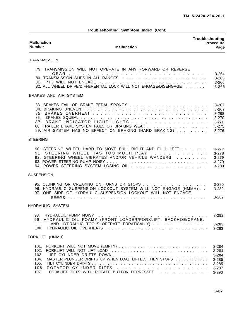
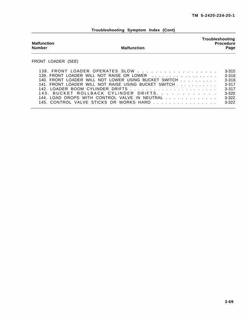
Section IV Troubleshooting Procedures .................................................................................... 3-63 INDEX....................................................................................................................... Index-1
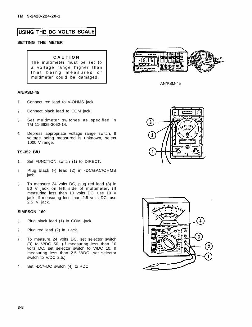
Section I Power Package Maintenance .................................................................................. 4-2
Section II Clutch Maintenance.................................................................................................. 4-12 Section III Fuel System Maintenance........................................................................................ 4-24
Section IV Exhaust System Maintenance.................................................................................. 4-79
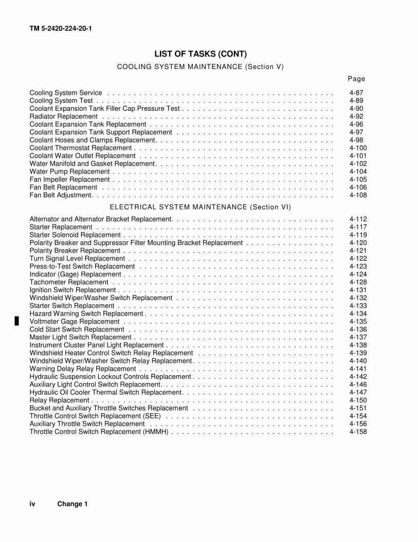
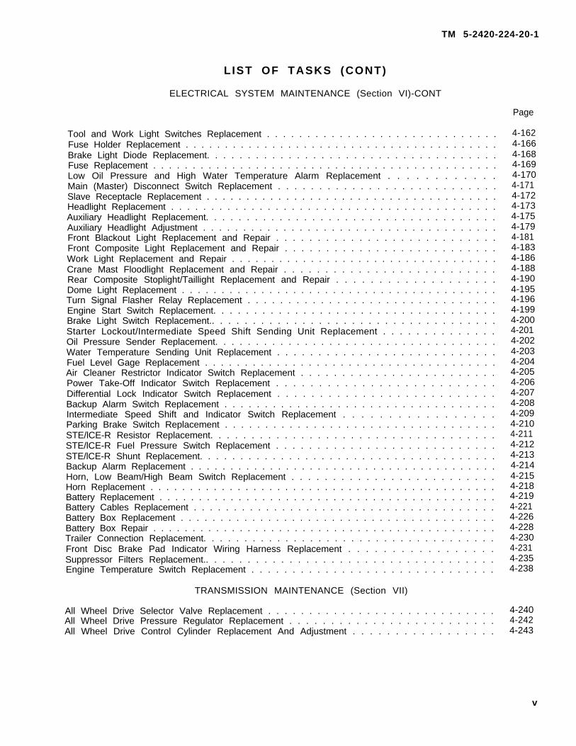
Section V Cooling System Maintenance .................................................................................. 4-86 Section VI Electrical System Maintenance ................................................................................ 4-109
Section VII Transmission Maintenance ...................................................................................... 4-240
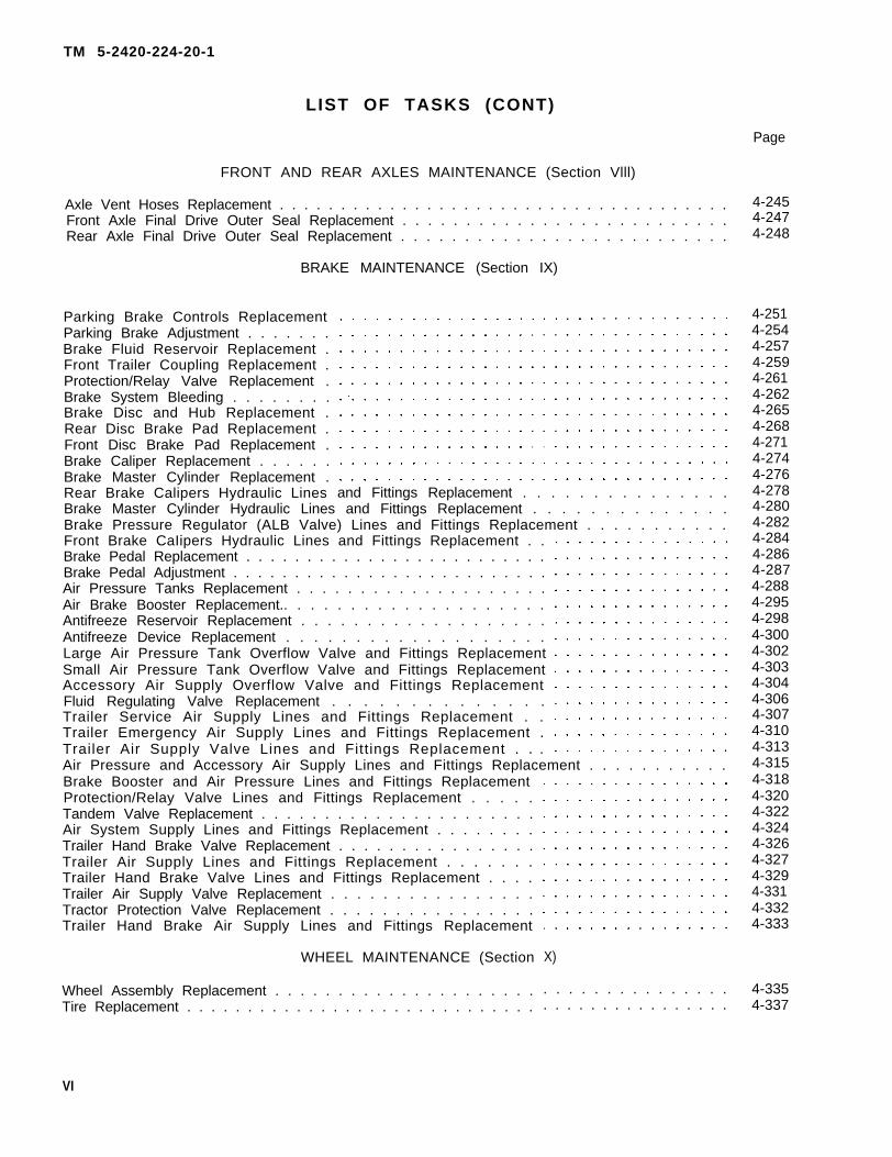
Section VIII Front and Rear Axles Maintenance.......................................................................... 4-245 Section IX Brake Maintenance .................................................................................................. 4-249
Section X Wheel Maintenance.................................................................................................. 4-335
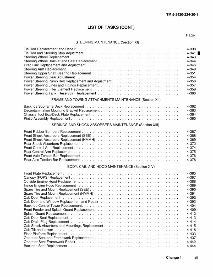
Section XI Steering Maintenance .............................................................................................. 4-338 Section XII Frame and Towing Attachments Maintenance......................................................... 4-362
Section XIII Springs and Shock Absorbers Maintenance............................................................ 4-367
Section XIV Body, Cab, and Hood Maintenance ......................................................................... 4-384 Section XV Body and Chassis Accessory Items Maintenance ................................................... 4-474
Section XVI Hydraulic System Maintenance................................................................................ 4-499
Section XVII Gages (Non-Electrical) Maintenance ....................................................................... 4-727 Section XVIII Machine Tools and Related Equipment Maintenance ............................................. 4-736
Section XIX Cranes, Shovels, and Earthmoving Equipment Components Maintenance............ 4-751
APPENDIX A REFERENCES......................................................................................................... A-1 APPENDIX B MAINTENANCE ALLOCATION CHART.................................................................. B-1
APPENDIX C EXPENDABLE SUPPLIES AND MATERIALS LIST................................................ C-1
APPENDIX D ILLUSTRATED LIST OF MANUFACTURED ITEMS............................................... D-1 APPENDIX E TORQUE LIMITS ..................................................................................................... E-1
HOW TO USE THIS MANUAL This manual has an edge index that will help you find specific information in a hurry. Simply spread the pages in the right edge of the manual until the printed blocks can be seen. Open the manual where the block on the edge of the page lines up with your selected topic printed in the front cover block.
OVERVIEW This manual is organized by chapters, sections, and appendices. A summary of the organization of this manual, by major divisions, follows:
Front cover index gives you a quick reference to chapters, sections, and appendices that you will use often.
WARNINGS—All warnings you should observe while working on or around the SEE/HMMH are shown in this part of the manual. These are repeated in the parts of the manual where they apply.
Table of Contents—The contents of the chapters and appendices are listed here.
Chapter 1—This chapter contains general information about the SEE/HMMH. It also shows and describes major components and lists specific data that you will find helpful while performing maintenance tasks.
Chapter 2—This chapter describes services and inspections that must be performed at the unit level, such as services you must perform upon receipt of the vehicle, preventive maintenance checks and services, and lubrication instructions. Other sections contain painting and restenciling of markings and general repair and cleaning methods.
Chapter 3—This chapter outlines troubleshooting of the SEE/HMMH and their systems. It includes a troubleshooting index, by symptom and system, and procedures on how to use the STE/ICE R components while troubleshooting.
Chapter 4—This chapter contains step-by-step instructions for doing the maintenance tasks. Each system of the SEE/HMMH has its own section within the chapter, and any special tools, equipment, or supplies you may need for a task are listed.
Appendix A—This appendix lists the technical manuals and other publications you may have to refer to while working on the SEE/HMMH.
Appendix B—This appendix contains the Maintenance Allocation Chart (MAC) for the SEE/HMMH.
Appendix C—This appendix lists the expendable supplies and materials you will need while performing maintenance on the SEE/HMMH.
Appendix D—This appendix lists and describes any manufactured items you will need for performing maintenance on the SEE/HMMH.
Appendix E—This appendix describes the proper method of tightening fasteners.
Index—The index is an alphabetical listing of the contents of this manual.
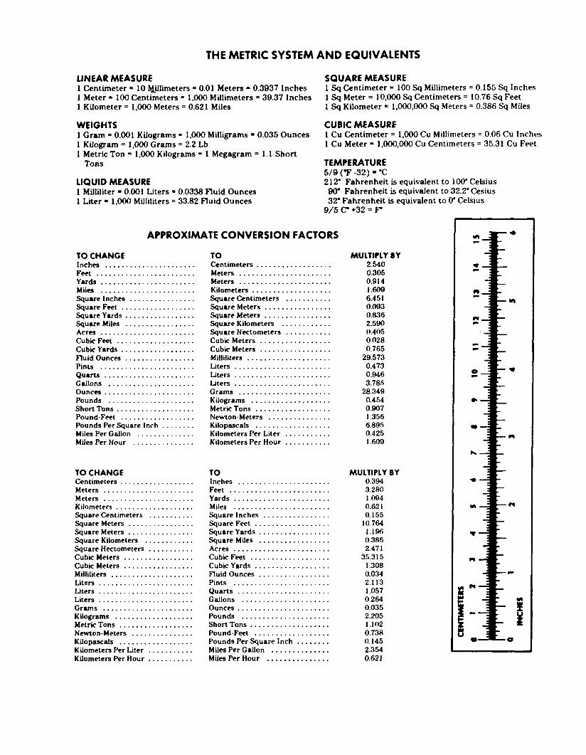
Back Cover—The inside back cover contains a metric conversion table.
xii Change 2
TM 5-2420-224-20-1
USING THE MANUAL ON THE JOB
Find the task or component that needs repair by using the LIST OF TASKS (page iii) or theIndex (page Index-1), then turn to the page listed for that task or component.
Read the INITIAL SETUP procedures, and gather the necessary items and personnel. Payattention to the warnings. The INITIAL SETUP sheet is described on page xiv.
Although tasks are complete in detail, complete only the part of the task required. For example,if your task is to replace both air cleaner elements, you need not perform the remainder of thetask to remove and replace the air cleaner canister.
xiii
TM 5-2420-224-20-1
TM 5-2420-224-20-2
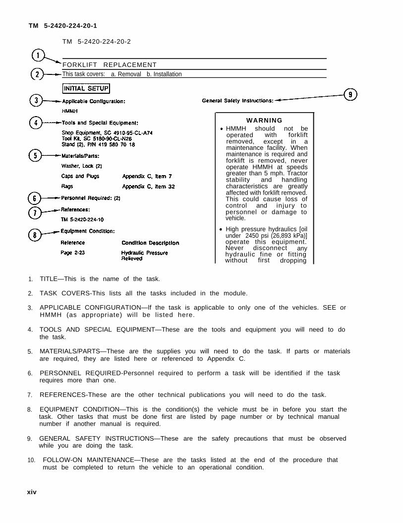
FORKLIFT REPLACEMENTThis task covers: a. Removal b. Installation
1.
2.
3.
4.
5.
6.
7.
8.
9.
10.
TITLE—This is the name of the task.
WARNIN G HMMH should not be
operated with forkliftremoved, except in amaintenance facility. Whenmaintenance is required andforklift is removed, neveroperate HMMH at speedsgreater than 5 mph. Tractorstability and handlingcharacteristics are greatlyaffected with forklift removed.This could cause loss ofcontrol and injury topersonnel or damage tovehicle.
High pressure hydraulics [oilunder 2450 psi (26,893 kPa)]operate this equipment.Never disconnect anyhydraulic fine or fittingwithout first dropping
TASK COVERS-This lists all the tasks included in the module.
APPLICABLE CONFIGURATION—lf the task is applicable to only one of the vehicles. SEE orHMMH (as appropriate) will be listed here.
TOOLS AND SPECIAL EQUIPMENT—These are the tools and equipment you will need to dothe task.
MATERIALS/PARTS—These are the supplies you will need to do the task. If parts or materialsare required, they are listed here or referenced to Appendix C.
PERSONNEL REQUIRED-Personnel required to perform a task will be identified if the taskrequires more than one.
REFERENCES-These are the other technical publications you will need to do the task.
EQUIPMENT CONDITION—This is the condition(s) the vehicle must be in before you start thetask. Other tasks that must be done first are listed by page number or by technical manualnumber if another manual is required.
GENERAL SAFETY lNSTRUCTIONS—These are the safety precautions that must be observedwhile you are doing the task.
FOLLOW-ON MAINTENANCE—These are the tasks listed at the end of the procedure thatmust be completed to return the vehicle to an operational condition.
xiv
TM 5-2420-224-20-1
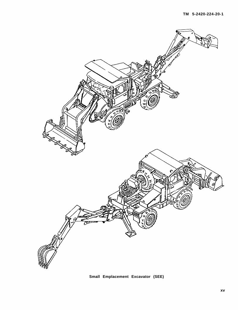
Small Emplacement Excavator (SEE)
xv
TM 5-2420-224-20-1
High Mobility Material Handler (HMMH)
xvi
TM 5-2420-224-20-1
Change 1 1-1
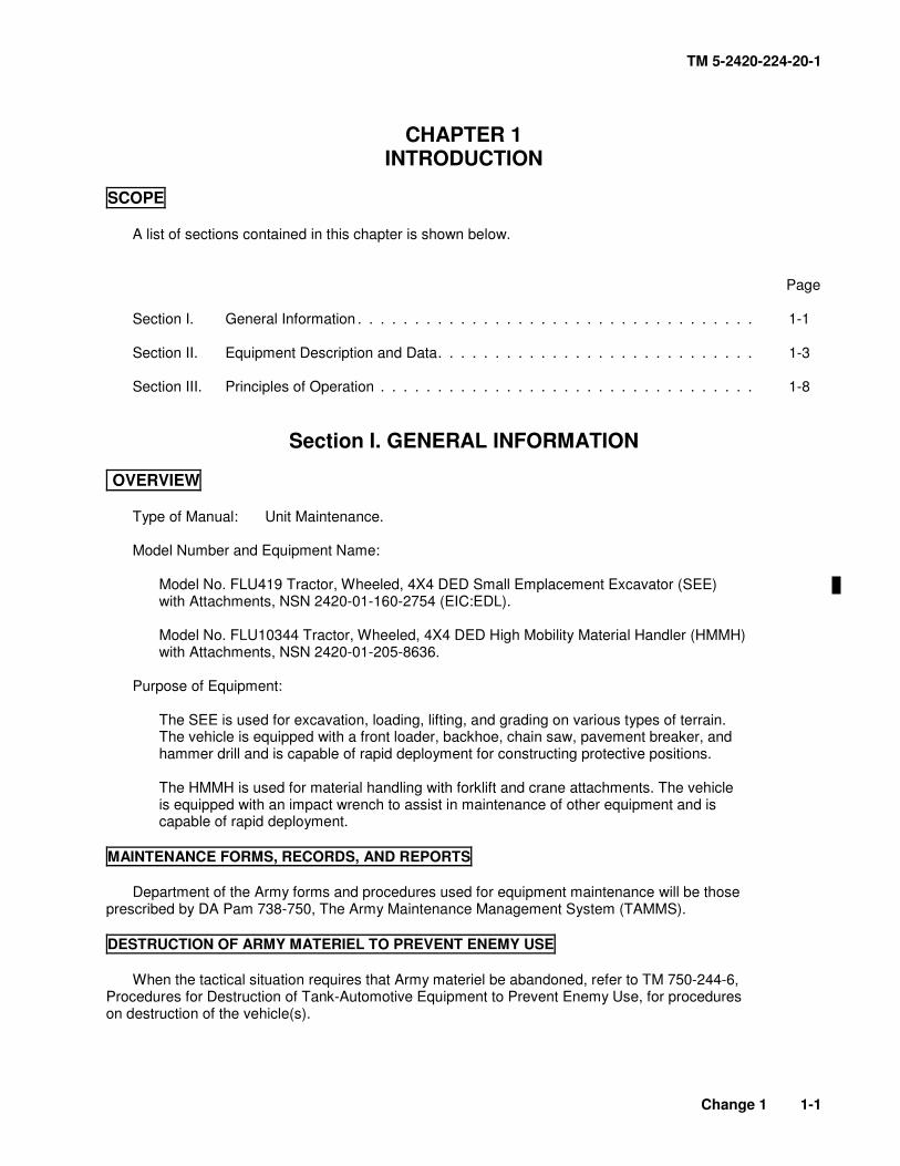
CHAPTER 1 INTRODUCTION
SCOPE
A list of sections contained in this chapter is shown below. Page
Model No. FLU419 Tractor, Wheeled, 4X4 DED Small Emplacement Excavator (SEE) with Attachments, NSN 2420-01-160-2754 (EIC:EDL).
Model No. FLU10344 Tractor, Wheeled, 4X4 DED High Mobility Material Handler (HMMH) with Attachments, NSN 2420-01-205-8636.
Purpose of Equipment:
The SEE is used for excavation, loading, lifting, and grading on various types of terrain. The vehicle is equipped with a front loader, backhoe, chain saw, pavement breaker, and hammer drill and is capable of rapid deployment for constructing protective positions. The HMMH is used for material handling with forklift and crane attachments. The vehicle is equipped with an impact wrench to assist in maintenance of other equipment and is capable of rapid deployment.
MAINTENANCE FORMS, RECORDS, AND REPORTS
Department of the Army forms and procedures used for equipment maintenance will be those
prescribed by DA Pam 738-750, The Army Maintenance Management System (TAMMS).
DESTRUCTION OF ARMY MATERIEL TO PREVENT ENEMY USE
When the tactical situation requires that Army materiel be abandoned, refer to TM 750-244-6,
Procedures for Destruction of Tank-Automotive Equipment to Prevent Enemy Use, for procedures on destruction of the vehicle(s).
TM 5-2420-224-20-1
1-2 Change 1
PREPARATION FOR STORAGE OR SHIPMENT
Instructions for storage and shipment, including administrative storage, are found in TM 740-90-1, MIL-V-62038D, and Chapter 2, Section VII.
If your vehicle needs improvement, let us know. Send us a Quality Deficiency Report. You, the user, are the only one who can tell us what you don’t like about your equipment. Let us know why you don’t like the design or performance. Put it on an SF Form 368 (QDR) and mail it to: U.S. Tank-automotive and Armaments Command Attn: AMSTA-TR-E/PQDR MS 267 6501 E. 11 Mile Road Warren, MI 48397-5000
WARRANTY INFORMATION
The vehicles are warranted by Freightliner Corporation in accordance with TB 5-2420-224-15. Warranty starts on the date found in block 23, DA Form 2408-9 in the logbook. Report all defects in material or workmanship to your supervisor, who will take appropriate action through your unit maintenance shop.
METRIC SYSTEM
The equipment described herein contains metric components and requires metric common and special tools; therefore, metric units in addition to English units will be used throughout the manual. An English-to-metric conversion table is included as the last page of this manual inside the back cover.
TM 5-2420-224-20-1
Sect ion I I . EQUIPMENT DESCRIPTION AND DAT A
This section contains information useful when performing unit level maintenance tasks on theSEE/HMMH. Refer to TM 5-2420-224-10 for additional equipment description and data.
EQUIPMENT CHARACTERISTICS, CAPABIL IT IES, AND FEATURE S
Characteristics
Low center of gravity for stability
Convoy speed
Small turning radius
17-in. (43.2-cm) ground clearance under axles and frame
Rapid deployment
Multiple attachment versatility
Capabilities and Features
Broad range of angles of approach and departure
Four-wheel drive and differential locks on both axles can be engaged and disengagedwhile moving
High-mounted air intake and vertical exhaust
Traverse up and down 60% slopes and 30% side slopes
30-in. (76.2-cm) fording depth
Power assisted disc brakes on all four wheels
Power steering
All steel cab
Roll-Over Protective Structure (ROPS)
Falling Objects Protective Structure (FOPS)
Utility mounting platforms
Trailer towing equipment
Front loader/forklift or backhoe/crane and machine (hydraulic) tools can be operatedsimultaneously
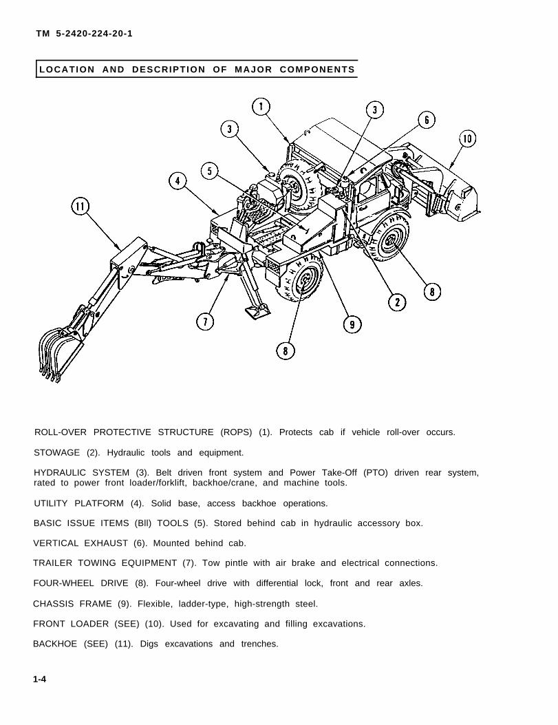
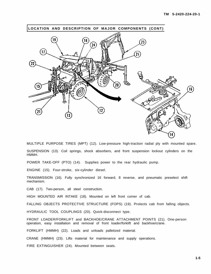
HYDRAULIC SYSTEM (3). Belt driven front system and Power Take-Off (PTO) driven rear system,rated to power front loader/forklift, backhoe/crane, and machine tools.
FRONT LOADER/FORKLIFT and BACKHOE/CRANE ATTACHMENT POINTS (21). One-personoperation, easy installation and removal of front loader/forklift and backhoe/crane.
FORKLIFT (HMMH) (22). Loads and unloads palletized material.
CRANE (HMMH) (23). Lifts material for maintenance and supply operations.
FIRE EXTINGUISHER (24). Mounted between seats.
1-5
TM 5-2420-224-20-1
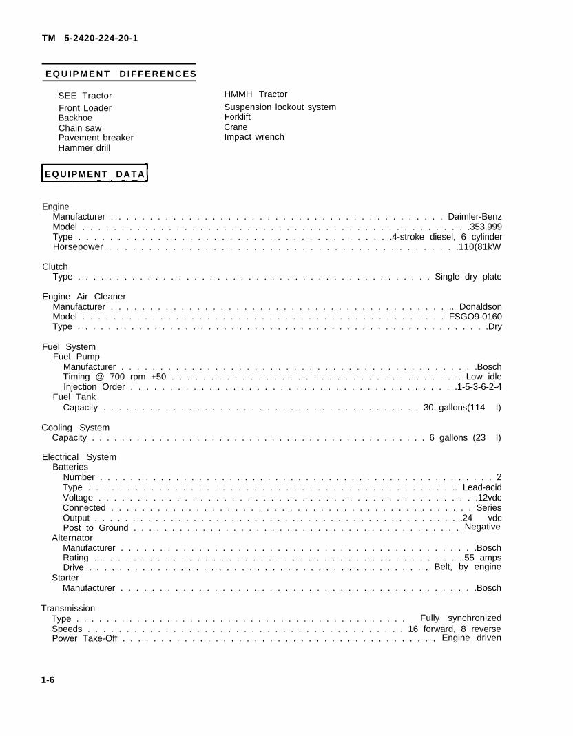
E Q U I P M E N T D I F F E R E N C E S
SEE TractorFront LoaderBackhoeChain sawPavement breakerHammer drill
Warnings and cautions are listed in the front of the manual, at the beginning of each task, and at points where they apply in the maintenance procedures. In addition to these warnings, alwayskeep in mind the following when working on the SEE/HMMH:
The hydraulic system operates at pressures up to 2450 psi (167 bar).
Be aware of where personnel are at all times when operating front Ioader/forklift andbackhoe/crane.
Do not allow personnel to walk under a raised front loader/forklift or backhoe/crane eitherduring operation or maintenance.
Always remove all jewelry and wristwatch, and make sure the vehicle MASTER disconnectswitch is OFF before working on the electrical system.
S e c t i o n I l l . P R I N C I P L E S O F O P E R A T I O N
O V E R V I E W
This section contains information on the principles of operation of the SEE/HMMH. The generalfunctional description of the vehicle’s separate systems is contained in this section. Unit maintenancepersonnel should be familiar with the principles of operation of these systems before working on ortroubleshooting these systems. A more thorough understanding of the electrical system can beobtained by referring to the electrical system schematic diagrams In the troubleshooting section InChapter 3. The systems and components are:
Page Crane (HMMH) ................................................................................................................................ 1-15 Crane Controls (HMMH) .................................................................................................................. 1-15 Hydraulic System Front System ................................................................................................................................... 1-16 Rear System .................................................................................................................................... 1-16 Air System ........................................................................................................................................... 1-16 Machine (Hydraulic) Tools Chain Saw (SEE).............................................................................................................................. 1-17 Pavement Breaker (SEE) ................................................................................................................. 1-17 Hammer Drill (SEE) .......................................................................................................................... 1-17 Impact Wrench (HMMH)................................................................................................................... 1-17
POWER TRAIN
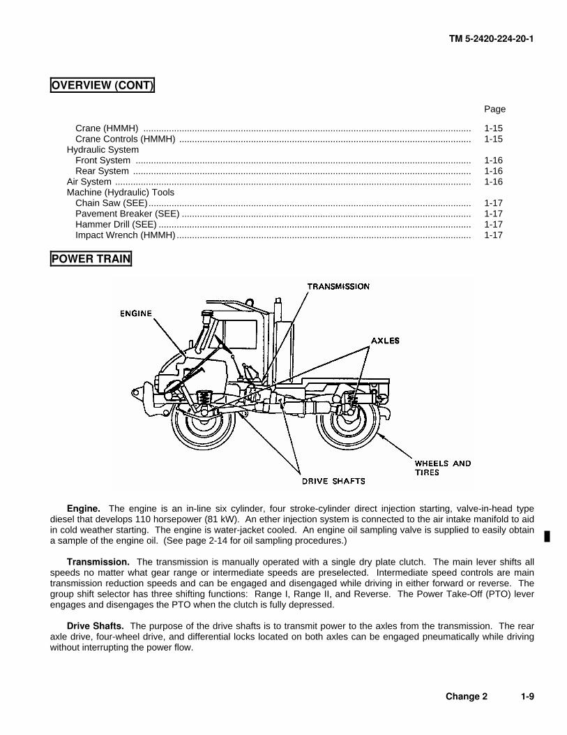
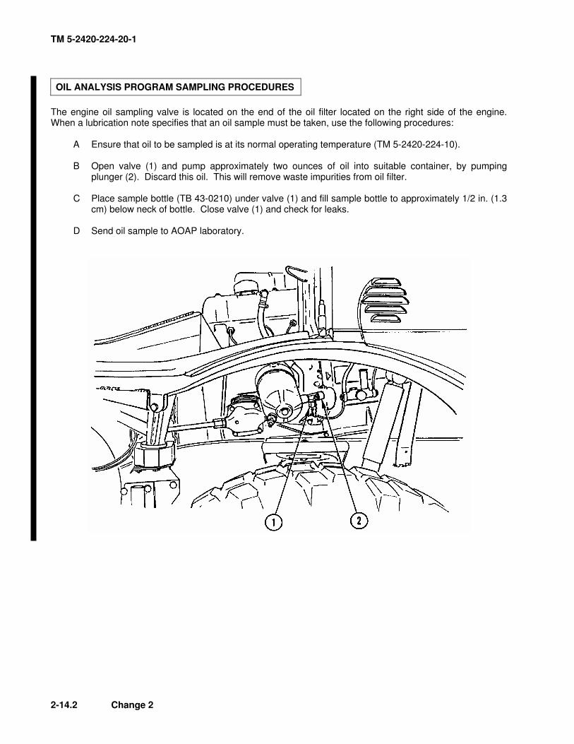
Engine. The engine is an in-line six cylinder, four stroke-cylinder direct injection starting, valve-in-head type diesel that develops 110 horsepower (81 kW). An ether injection system is connected to the air intake manifold to aid in cold weather starting. The engine is water-jacket cooled. An engine oil sampling valve is supplied to easily obtain a sample of the engine oil. (See page 2-14 for oil sampling procedures.) Transmission. The transmission is manually operated with a single dry plate clutch. The main lever shifts all speeds no matter what gear range or intermediate speeds are preselected. Intermediate speed controls are main transmission reduction speeds and can be engaged and disengaged while driving in either forward or reverse. The group shift selector has three shifting functions: Range I, Range II, and Reverse. The Power Take-Off (PTO) lever engages and disengages the PTO when the clutch is fully depressed. Drive Shafts. The purpose of the drive shafts is to transmit power to the axles from the transmission. The rear axle drive, four-wheel drive, and differential locks located on both axles can be engaged pneumatically while driving without interrupting the power flow.
Change 2 1-9
TM 5-2420-224-20-1
POWER TRAIN (CONT)
Axles. There are two portal axles with hub reduction thrust tube mounted.
Wheels and Tires. Multipurpose tires are mounted on solid disc type wheels with the front andrear tires being equal in size. The rim size is 11.00-20, tire size is 12.5 R20 12 PR radial, andthe track width is 64 in. (163 cm).
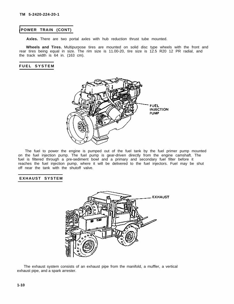
F U E L S Y S T E M
The fuel to power the engine is pumped out of the fuel tank by the fuel primer pump mountedon the fuel injection pump. The fuel pump is gear-driven directly from the engine camshaft. Thefuel is filtered through a pre-sediment bowl and a primary and secondary fuel filter before itreaches the fuel injection pump, where it will be delivered to the fuel injectors. Fuel may be shutoff near the tank with the shutoff valve.
E X H A U S T S Y S T E M
The exhaust system consists of an exhaust pipe from the manifold, a muffler, a verticalexhaust pipe, and a spark arrester.
1-10
TM 5-2420-224-20-1
C O O L I N G S Y S T E M
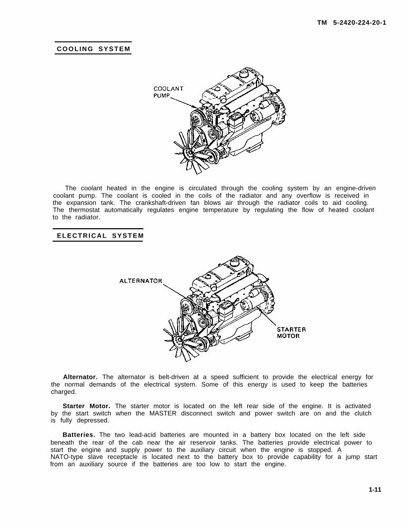
The coolant heated in the engine is circulated through the cooling system by an engine-drivencoolant pump. The coolant is cooled in the coils of the radiator and any overflow is received inthe expansion tank. The crankshaft-driven fan blows air through the radiator coils to aid cooling.The thermostat automatically regulates engine temperature by regulating the flow of heated coolantto the radiator.
E L E C T R I C A L S Y S T E M
Alternator. The alternator is belt-driven at a speed sufficient to provide the electrical energy forthe normal demands of the electrical system. Some of this energy is used to keep the batteriescharged.
Starter Motor. The starter motor is located on the left rear side of the engine. It is activatedby the start switch when the MASTER disconnect switch and power switch are on and the clutchis fully depressed.
Batteries. The two lead-acid batteries are mounted in a battery box located on the left sidebeneath the rear of the cab near the air reservoir tanks. The batteries provide electrical power tostart the engine and supply power to the auxiliary circuit when the engine is stopped. ANATO-type slave receptacle is located next to the battery box to provide capability for a jump startfrom an auxiliary source if the batteries are too low to start the engine.
1-11
TM 5-2420-224-20-1
ELECTRICAL SYSTEM (CONT )
Switches and Gages. Refer to TM 5-2420-224-10 for the locations and detailed descriptions of the switches and gages.
Sending Units. The intermediate speed indicator is located on the right side of thetransmission; the parking brake indicator is located on the cable lever at the center of the rearaxle; the low air warning indicator is located on the air line to the trailer air brake valve; thePower Take-Off (PTO) indicator is located on the left side of the transmission housing at the PTOhousing; the fuel level sending indicator is located on the right side top of the fuel tank; theneutral start switch indicator is located under the clutch pedal on the left side of the cab.
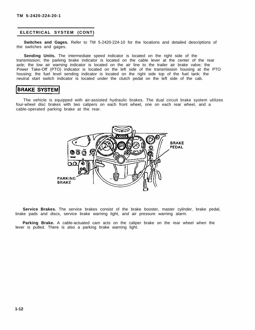
The vehicle is equipped with air-assisted hydraulic brakes. The dual circuit brake system utilizesfour-wheel disc brakes with two calipers on each front wheel, one on each rear wheel, and acable-operated parking brake at the rear.
Service Brakes. The service brakes consist of the brake booster, master cylinder, brake pedal,brake pads and discs, service brake warning light, and air pressure warning alarm.
Parking Brake. A cable-actuated cam acts on the caliper brake on the rear wheel when thelever is pulled. There is also a parking brake warning light.
1-12
TM 5-2420-224-20-1
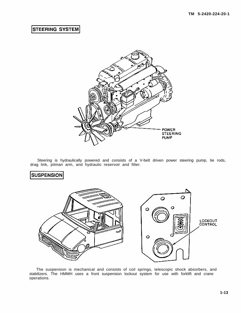
Steering is hydraulically powered and consists of a V-belt driven power steering pump, tie rods,drag link, pitman arm, and hydraulic reservoir and filter.
The suspension is mechanical and consists of coil springs, telescopic shock absorbers, andstabilizers. The HMMH uses a front suspension lockout system for use with forklift and craneoperations.
1-13
TM 5-2420-224-20-1
EARTHMOVING, MATERIAL HANDLING COMPONENTS AND CONTROL S
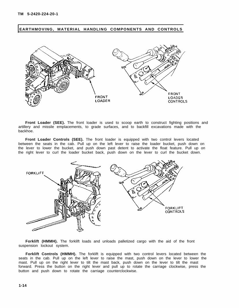
Front Loader (SEE). The front loader is used to scoop earth to construct fighting positions andartillery and missile emplacements, to grade surfaces, and to backfill excavations made with thebackhoe.
Front Loader Controls (SEE). The front loader is equipped with two control levers locatedbetween the seats in the cab. Pull up on the left lever to raise the loader bucket, push down onthe lever to lower the bucket, and push down past detent to activate the float feature. Pull up onthe right lever to curl the loader bucket back, push down on the lever to curl the bucket down.
Forklift (HMMH). The forklift loads and unloads palletized cargo with the aid of the frontsuspension lockout system.
Forklift Controls (HMMH). The forklift is equipped with two control levers located between theseats in the cab. Pull up on the left lever to raise the mast, push down on the lever to lower themast. Pull up on the right lever to tilt the mast back, push down on the lever to tilt the mastforward. Press the button on the right lever and pull up to rotate the carriage clockwise, press thebutton and push down to rotate the carriage counterclockwise.
1-14
TM 5-2420-224-20-1
EARTHMOVING, MATERIAL HANDLING COMPONENTS AND CONTROLS (CONT )
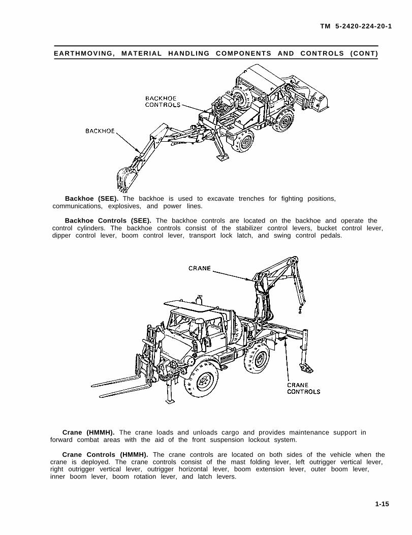
Backhoe (SEE). The backhoe is used to excavate trenches for fighting positions,communications, explosives, and power lines.
Backhoe Controls (SEE). The backhoe controls are located on the backhoe and operate thecontrol cylinders. The backhoe controls consist of the stabilizer control levers, bucket control lever,dipper control lever, boom control lever, transport lock latch, and swing control pedals.
Crane (HMMH). The crane loads and unloads cargo and provides maintenance support inforward combat areas with the aid of the front suspension lockout system.
Crane Controls (HMMH). The crane controls are located on both sides of the vehicle when thecrane is deployed. The crane controls consist of the mast folding lever, left outrigger vertical lever,right outrigger vertical lever, outrigger horizontal lever, boom extension lever, outer boom lever,inner boom lever, boom rotation lever, and latch levers.
1-15
TM 5-2420-224-20-1
HYDRAULIC SYSTE M
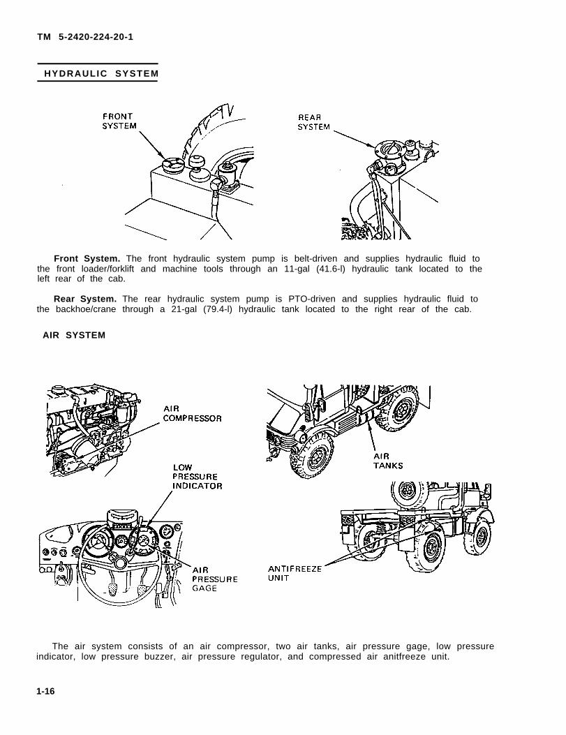
Front System. The front hydraulic system pump is belt-driven and supplies hydraulic fluid tothe front loader/forklift and machine tools through an 11-gal (41.6-l) hydraulic tank located to theleft rear of the cab.
Rear System. The rear hydraulic system pump is PTO-driven and supplies hydraulic fluid tothe backhoe/crane through a 21-gal (79.4-l) hydraulic tank located to the right rear of the cab.
AIR SYSTEM
The air system consists of an air compressor, two air tanks, air pressure gage, low pressureindicator, low pressure buzzer, air pressure regulator, and compressed air anitfreeze unit.
1-16
TM
5-2
420-2
24-2
0-1
Ch
an
ge 1
1-1
6.1
AIR
SY
ST
EM
(CO
NT
)
TM
5-2
420-2
24-2
0-1
1-1
6.2
C
han
ge 1
!
AIR
SY
ST
EM
(CO
NT
)
TM 5-2420-224-20-1
Change 1 1-16.3
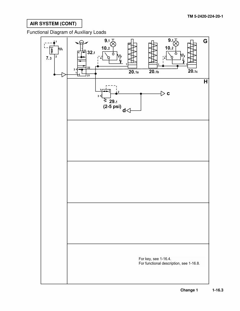
Functional Diagram of Auxiliary Loads
AIR SYSTEM (CONT)
TM 5-2420-224-20-1
1-16.4 Change 1
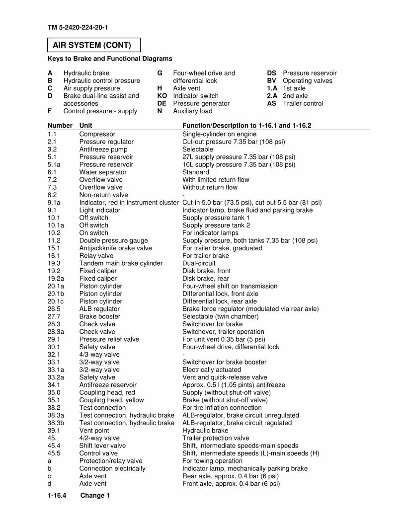
Keys to Brake and Functional Diagrams
A Hydraulic brake B Hydraulic control pressure C Air supply pressure D Brake dual-line assist and accessories F Control pressure - supply
G Four-wheel drive and differential lock
H Axle vent KO Indicator switch DE Pressure generator N Auxiliary load
DS Pressure reservoir BV Operating valves 1.A 1st axle 2.A 2nd axle AS Trailer control
Number Unit Function/Description to 1-16.1 and 1-16.2
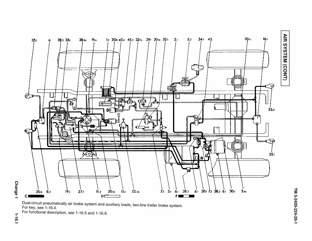
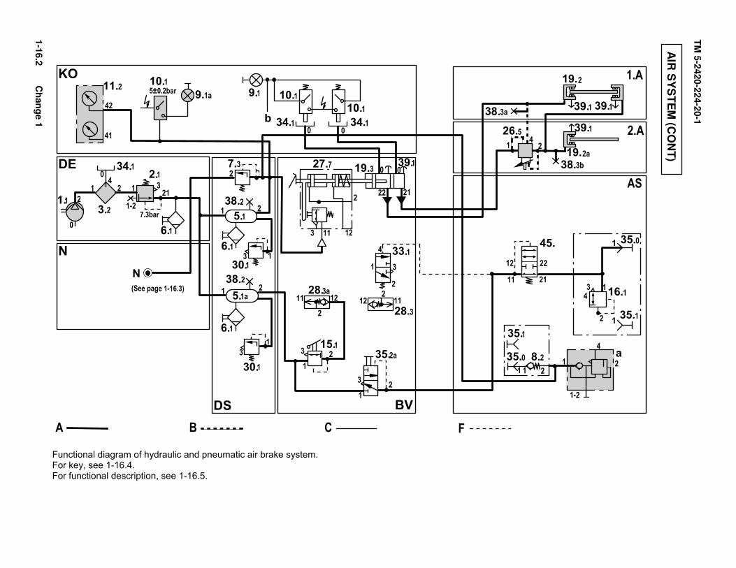
1.1 Compressor Single-cylinder on engine 2.1 Pressure regulator Cut-out pressure 7.35 bar (108 psi) 3.2 Antifreeze pump Selectable 5.1 Pressure reservoir 27L supply pressure 7.35 bar (108 psi) 5.1a Pressure reservoir 10L supply pressure 7.35 bar (108 psi) 6.1 Water separator Standard 7.2 Overflow valve With limited return flow 7.3 Overflow valve Without return flow 8.2 Non-return valve - 9.1a Indicator, red in instrument cluster Cut-in 5.0 bar (73.5 psi), cut-out 5.5 bar (81 psi) 9.1 Light indicator Indicator lamp, brake fluid and parking brake 10.1 Off switch Supply pressure tank 1 10.1a Off switch Supply pressure tank 2 10.2 On switch For indicator lamps 11.2 Double pressure gauge Supply pressure, both tanks 7.35 bar (108 psi) 15.1 Antijackknife brake valve For trailer brake, graduated 16.1 Relay valve For trailer brake 19.3 Tandem main brake cylinder Dual-circuit 19.2 Fixed caliper Disk brake, front 19.2a Fixed caliper Disk brake, rear 20.1a Piston cylinder Four-wheel shift on transmission 20.1b Piston cylinder Differential lock, front axle 20.1c Piston cylinder Differential lock, rear axle 26.5 ALB regulator Brake force regulator (modulated via rear axle) 27.7 Brake booster Selectable (twin chamber) 28.3 Check valve Switchover for brake 28.3a Check valve Switchover, trailer operation 29.1 Pressure relief valve For unit vent 0.35 bar (5 psi) 30.1 Safety valve Four-wheel drive, differential lock 32.1 4/3-way valve - 33.1 3/2-way valve Switchover for brake booster 33.1a 3/2-way valve Electrically actuated 33.2a Safety valve Vent and quick-release valve 34.1 Antifreeze reservoir Approx. 0.5 l (1.05 pints) antifreeze 35.0 Coupling head, red Supply (without shut-off valve) 35.1 Coupling head, yellow Brake (without shut-off valve) 38.2 Test connection For tire inflation connection 38.3a Test connection, hydraulic brake ALB-regulator, brake circuit unregulated 38.3b Test connection, hydraulic brake ALB-regulator, brake circuit regulated 39.1 Vent point Hydraulic brake 45. 4/2-way valve Trailer protection valve 45.4 Shift lever valve Shift, intermediate speeds-main speeds 45.5 Control valve Shift, intermediate speeds (L)-main speeds (H) a Protection/relay valve For towing operation b Connection electrically Indicator lamp, mechanically parking brake c Axle vent Rear axle, approx. 0.4 bar (6 psi) d Axle vent Front axle, approx. 0.4 bar (6 psi)
AIR SYSTEM (CONT)
TM 5-2420-224-20-1
Change 1 1-16.5
Functional Description of the Dual-Circuit Air Brake System The compressed air generated by the engine compressor (1.1) is directed to the antifreeze pump (3.2) from which it reaches the pressure regulator (2.1) automatically mixed with antifreeze during winter operation. The pressure regulator filters the air and limits the system pressure to 107 PSI/7.35 bar (operating pressure). The pressure regulator is equipped with an inflation connection. For inflating tires, the operating pressure is reduced below 87 PSI/6.0 bar (cut-in pressure of the pressure of the pressure regulator 90 PSI/6.2 bar). The two air tanks (5.1), 27 l capacity, and (5.1a), 10 l capacity, are filled simultaneously. The air tanks are equipped with safety valves (30.1) which open in the case of fault or at excess pressure (approx. 131 PSI/9.0 bar). Two overflow valves (7.2) maintain the pressure in the air tanks. From a pressure of 75 PSI/5.2 bar, both tanks are connected by means of overflow. A test connection is provided at each output of the pressure tanks.
Compressed air can be obtained at both the pressure regulator and at the pressure tanks. The air tank (5.1) contains supply pressure for the trailer brake booster (27.2), the trailer protection valve (a) and the auxiliary consumers. Air tank pressure is indicated by means of a dual pressure gauge (11.2) and monitored via a warning light (9.1) and a warning buzzer. The air tank (5.1a) provides compressed air to the trailer brake system, the antijackknife brake valve (15.1) and the safety valve (33.2). For trailer operation, this valve (33.2a) is actuated- depressed by hand (push to supply trailer). The supply pressure flows to the trailer protection valve (45.) and from there further via the shut-off valve (8.3) and coupling head (35.0) to the trailer. (See trailer operation)
AIR SYSTEM (CONT)
TM 5-2420-224-20-1
1-16.6 Change 1
Single Operation The pressure in the hydraulic dual-circuit brake system is assisted by the brake booster (27.7). The brake booster (27.7) is designed as a twin chamber brake booster which transmits its full volume during single operation. For trailer operation, the outer chamber is cut out, thereby reducing the effect of the brake booster to approx. 70%. Pressure is applied to the double main brake cylinder (19.3) when the service brake is operated. At the same time, air is allowed to enter the brake booster (27.7). From output (2) of the brake booster, the compressed air flows further to the shuttle valve (28.3a), leaves output (2) and then reaches the trailer protection valve (45.) input (12). This valve is ineffective when not in trailer operation. This is also the case when the antijackknife brake valve (15.1) is actuated.
Without trailer operation, the air system only has an indirect function for the brake booster (27.7) and for the auxiliary consumers. (Refer to auxiliary consumers.) Trailer Operation The trailer will be provided with compressed air after coupling the supply and brake lines. However, supply air flows to the trailer only when the safety valve (33.2) is actuated. The actuating knob is depressed (push to supply trailer) until it remains in this position on its own accord (After approx. 2.8 bar pressure increase). As a result of this pressure increase, the passage for the control pressure into the relay valve (16.1) is opened in the trailer protection valve (45.).
AIR SYSTEM (CONT)
TM 5-2420-224-20-1
Change 1 1-16.7
The valve (16.1) enables fast entry and escape of air in the trailer brake system and maintains the control pressure in the case of leakage in the trailer brake line. When the safety valve (33.2a) is actuated, supply air also flows to the changeover valve (33.1) on the brake booster. This valve has the task of disconnecting the outer chamber of the brake booster (27.7) as already described. The reduction of the power assistance causes an improvement in braking characteristics during trailer operation. The antijackknife brake valve (15.1) is an additional service brake valve which only acts on the trailer. Its function can be graduated and is used particularly for braking the trailer on slight inclines, with the service brake in the tractor unit not being used along side this brake. The parking brake in the tractor vehicle acts mechanically on the rear wheels and has no effect on the trailer. When a vehicle with trailer is parked, both the vehicle and the trailer must be braked by means of its own parking brake.
Towing The vehicle is equipped with a brake system which permits compressed air supply from the towing vehicle, i.e., the system can be pressurized with supply air and braked from a towing vehicle, making it possible to maintain almost the same operating conditions as in the case of an intact vehicle. In this case, supply air flows via the front connection (35.0) to the large air tank; in this way, the auxiliary loads are also supplied. Control air flows to the brake valve (A) via the coupling head (35.1). The shuttle valve (28.3) is reversed by connection (2). In this way, the brake booster (27.7) is actuated via connection (4), i.e., only the outer booster chamber is effective.
AIR SYSTEM (CONT)
TM 5-2420-224-20-1
1-16.8 Change 1
Functional Description Auxiliary Loads N The auxiliary loads include:
• Four-wheel drive and differential locks (G)
• Axle vent (H)
• Intermediate speed shift (J) The compressed air supply of the brake system has priority, i.e., a minimum pressure of approx. 80 PSI/5.5 bar is first made available to the brake system. From a pressure of 80 PSI/5.5 bar, the auxiliary loads receive their supply via the overflow valve (7.3) up to an operating pressure of 107 PSI/7.35 bar. Four-Wheel Drive – Differential Locks The four-wheel drive is engaged in the transmission in position (1) of the changeover valve (32.1). In position (2) the differential locks of the axles are additionally activated. Axle Vent In both positions (1 and 2), the axles receive a compressed air supply at slight pressure for fording purposes.
This takes place by means of the pressure relief valve (29.1). The pressure is approx. 5 PSI/0.35 bar. Intermediate Speed Shift The intermediate speeds are pneumatically shifted with the aid of the shift lever valve (45.4). The control valve (45.5) provides the corresponding control pulses for air entry and escape in the shift cylinder (20.8) in the cascade box. The solenoid valve (33.1a) releases the supply air to the control valve (45.5) only when the clutch is operated in order to shift speeds. The valve (33.1a) is electronically actuated after the clutch pedal has been fully depressed down to the contact switch.
AIR SYSTEM (CONT)
TM 5-2420-224-20-1
Change 1 1-16.9
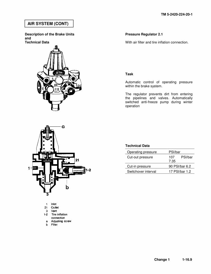
Description of the Brake Units and Technical Data
Pressure Regulator 2.1 With air filter and tire inflation connection. Task Automatic control of operating pressure within the brake system. The regulator prevents dirt from entering the pipelines and valves. Automatically switched anti-freeze pump during winter operation Technical Data
Operating pressure PSI/bar
Cut-out pressure 107 PSI/bar 7.35
Cut-in pressure 90 PSI/bar 6.2
Switchover interval 17 PSI/bar 1.2
AIR SYSTEM (CONT)
TM 5-2420-224-20-1
1-16.10 Change 1
Antifreeze Pump (3.2) Task By means of automatic metering, the pump injects antifreeze into the flow of air from the compressor, thereby preventing icing in the entire system. Function During the cut-out phase of the pressure regulator, a corresponding amount of antifreeze is supplied. When the pressure regulator (2.1) switches over to the delivery position, antifreeze is injected into the brake system via the non-return valve (7).
Technical Data
Temperature range -40°
Operating pressure max. bar 20
min. bar 6
Delivered capacity Position 0 1
Per stroke cm³ Off 0.5
Reservoir capacity I 0.5
Antifreeze: ethylalcohol
AIR SYSTEM (CONT)
TM 5-2420-224-20-1
Change 1 1-16.11
! " # $ % " " & ' ' " " " (
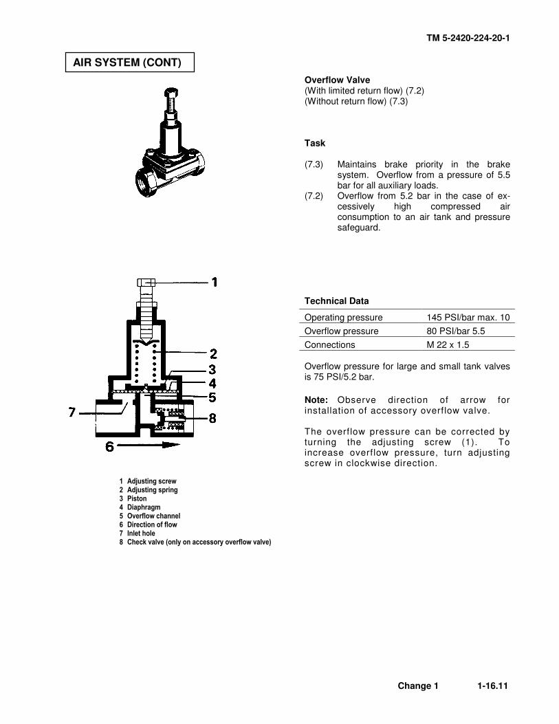
Overflow Valve (With limited return flow) (7.2) (Without return flow) (7.3) Task (7.3) Maintains brake priority in the brake
system. Overflow from a pressure of 5.5 bar for all auxiliary loads.
(7.2) Overflow from 5.2 bar in the case of ex-cessively high compressed air consumption to an air tank and pressure safeguard.
Technical Data
Operating pressure 145 PSI/bar max. 10
Overflow pressure 80 PSI/bar 5.5
Connections M 22 x 1.5
Overflow pressure for large and small tank valves is 75 PSI/5.2 bar.
Note: Observe direction of arrow for installation of accessory overflow valve. The overflow pressure can be corrected by turning the adjusting screw (1). To increase overflow pressure, turn adjusting screw in clockwise direction.
AIR SYSTEM (CONT)
TM 5-2420-224-20-1
1-16.12 Change 1
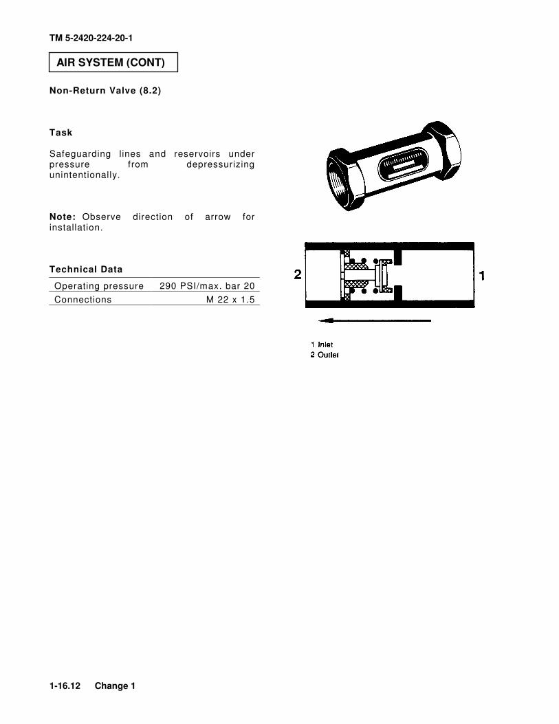
Non-Return Valve (8.2) Task Safeguarding lines and reservoirs under pressure from depressurizing unintentionally. Note: Observe direction of arrow for installation. Technical Data
Operating pressure 290 PSI/max. bar 20
Connections M 22 x 1.5
AIR SYSTEM (CONT)
TM 5-2420-224-20-1
Change 1 1-16.13
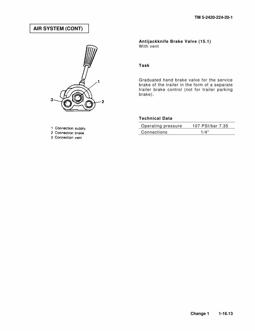
Antijackknife Brake Valve (15.1) With vent Task Graduated hand brake valve for the service brake of the trailer in the form of a separate trailer brake control (not for trailer parking brake). Technical Data
Operating pressure 107 PSI/bar 7.35
Connections 1/4”
AIR SYSTEM (CONT)
TM 5-2420-224-20-1
1-16.14 Change 1
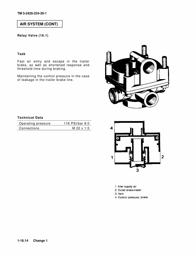
Relay Valve (16.1) Task Fast air entry and escape in the trailer brake, as well as shortened response and threshold time during braking. Maintaining the control pressure in the case of leakage in the trailer brake line.
Technical Data
Operating pressure 116 PSI/bar 8.0
Connections M 22 x 1.5
AIR SYSTEM (CONT)
TM 5-2420-224-20-1
Change 1 1-16.15
Single-Circuit Brake Booster (27.7) Full brake boosting effect stage I and II. Reduced brake boosting effect stage I. Task Boosting the hydraulic brake pressure with automatic switchover to reduced boosting effect for trailer operation. The switchover takes place by means of the supply pressure to the trailer which cuts out the outer ring chamber in the brake booster via the 3/2-way valve (33.1). Technical Data
Operating pressure max.
116 PSI/bar 8.0
Response pressure approx.
6 PSI/bar 0.4
Piston stroke mm 37
Piston diameter mm 150
Connections mm M 18 x 1.5
AIR SYSTEM (CONT)
TM 5-2420-224-20-1
1-16.16 Change 1
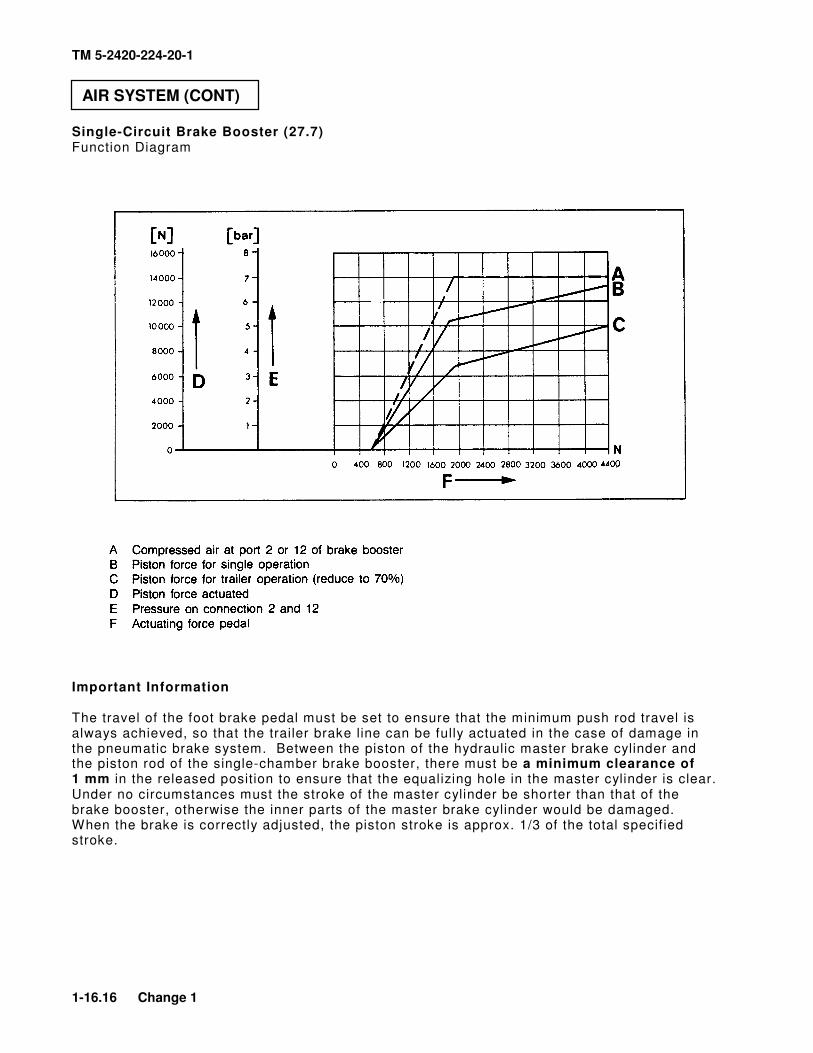
Single-Circuit Brake Booster (27.7) Function Diagram
Important Information The travel of the foot brake pedal must be set to ensure that the minimum push rod travel is always achieved, so that the trailer brake line can be fully actuated in the case of damage in the pneumatic brake system. Between the piston of the hydraulic master brake cylinder and the piston rod of the single-chamber brake booster, there must be a minimum clearance of 1 mm in the released position to ensure that the equalizing hole in the master cylinder is clear. Under no circumstances must the stroke of the master cylinder be shorter than that of the brake booster, otherwise the inner parts of the master brake cylinder would be damaged. When the brake is correctly adjusted, the piston stroke is approx. 1/3 of the total specif ied stroke.
AIR SYSTEM (CONT)
TM 5-2420-224-20-1
Change 1 1-16.17
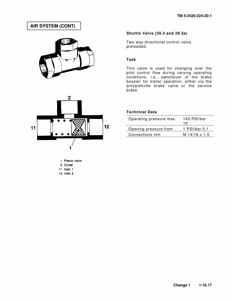
Shuttle Valve (28.3 and 28.3a) Two-way directional control valve, preloaded. Task This valve is used for changing over the pilot control f low during varying operating conditions, i.e., switchover of the brake booster for trailer operation, either via the antijackknife brake valve or the service brake. Technical Data
Operating pressure max. 145 PSI/bar 10
Opening pressure from 1 PSI/bar 0.1
Connections mm M 14/16 x 1.5
AIR SYSTEM (CONT)
TM 5-2420-224-20-1
1-16.18 Change 1
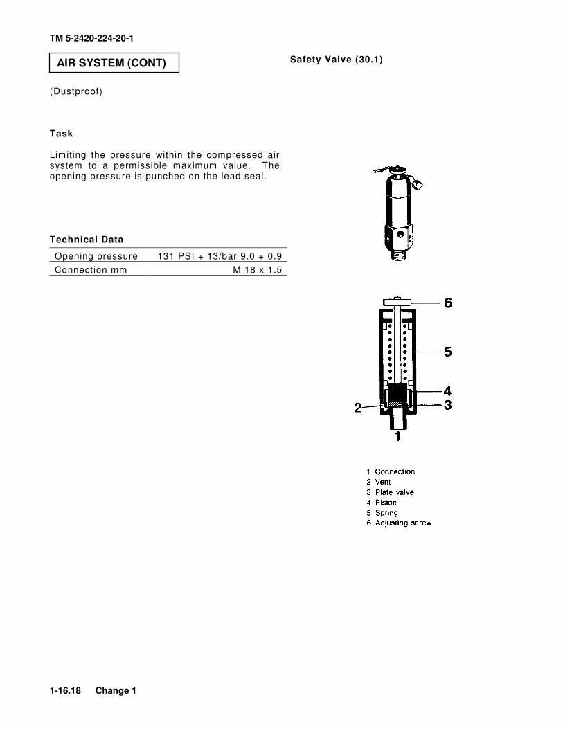
Safety Valve (30.1)
(Dustproof) Task Limiting the pressure within the compressed air system to a permissible maximum value. The opening pressure is punched on the lead seal. Technical Data
Opening pressure 131 PSI + 13/bar 9.0 + 0.9
Connection mm M 18 x 1.5
AIR SYSTEM (CONT)
TM 5-2420-224-20-1
Change 1 1-16.19
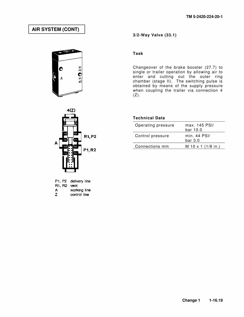
3/2-Way Valve (33.1) Task Changeover of the brake booster (27.7) to single or trailer operation by allowing air to enter and cutting out the outer ring chamber (stage II). The switching pulse is obtained by means of the supply pressure when coupling the trailer via connection 4 (Z). Technical Data
Operating pressure max. 145 PSI/ bar 10.0
Control pressure min. 44 PSI/ bar 3.0
Connections mm M 10 x 1 (1/8 in.)
AIR SYSTEM (CONT)
TM 5-2420-224-20-1
1-16.20 Change 1
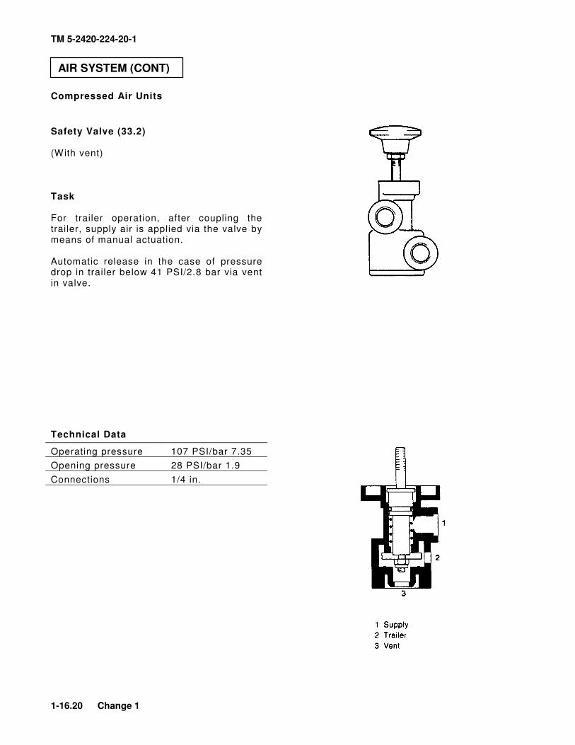
Compressed Air Units
Safety Valve (33.2) (With vent) Task For trailer operation, after coupling the trailer, supply air is applied via the valve by means of manual actuation. Automatic release in the case of pressure drop in trailer below 41 PSI/2.8 bar via vent in valve. Technical Data
Operating pressure 107 PSI/bar 7.35
Opening pressure 28 PSI/bar 1.9
Connections 1/4 in.
AIR SYSTEM (CONT)
TM 5-2420-224-20-1
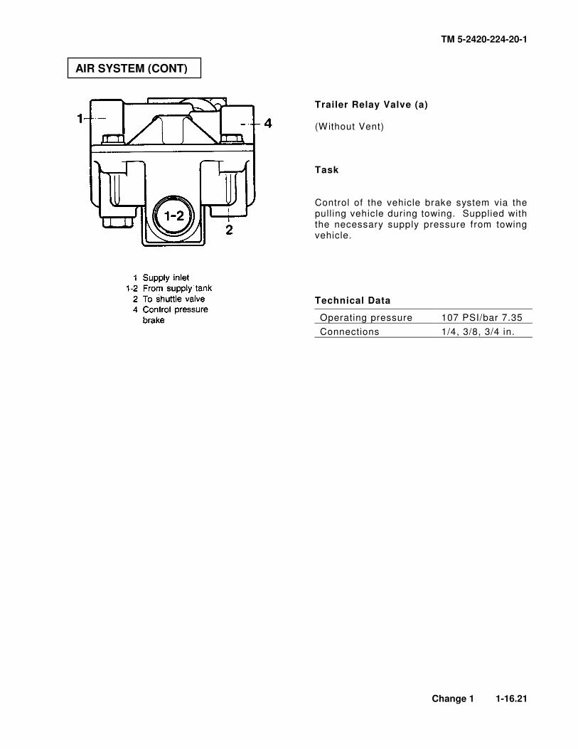
Change 1 1-16.21
Trailer Relay Valve (a) (Without Vent) Task Control of the vehicle brake system via the pulling vehicle during towing. Supplied with the necessary supply pressure from towing vehicle. Technical Data
Operating pressure 107 PSI/bar 7.35
Connections 1/4, 3/8, 3/4 in.
AIR SYSTEM (CONT)
TM 5-2420-224-20-1
1-16.22 Change 1
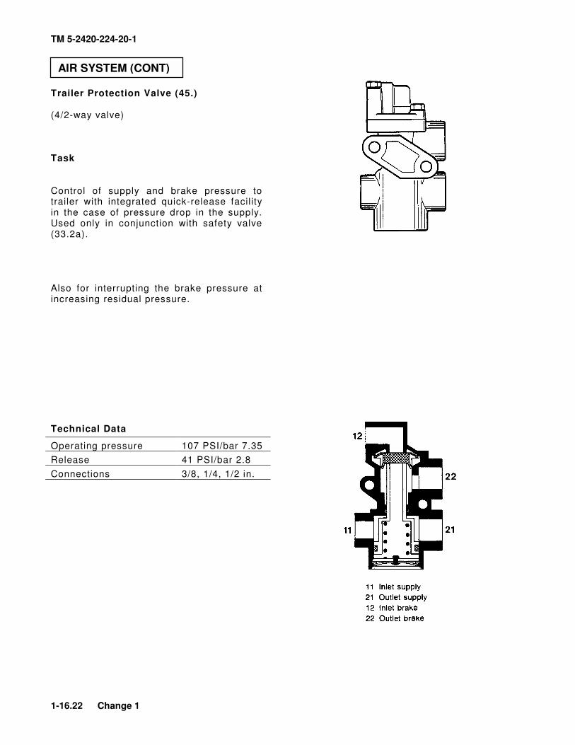
Trailer Protection Valve (45.) (4/2-way valve) Task Control of supply and brake pressure to trailer with integrated quick-release facility in the case of pressure drop in the supply. Used only in conjunction with safety valve (33.2a). Also for interrupting the brake pressure at increasing residual pressure. Technical Data
Operating pressure 107 PSI/bar 7.35
Release 41 PSI/bar 2.8
Connections 3/8, 1/4, 1/2 in.
AIR SYSTEM (CONT)
TM 5-2420-224-20-1
M A C H I N E ( H Y D R A U L I C ) T O O L S
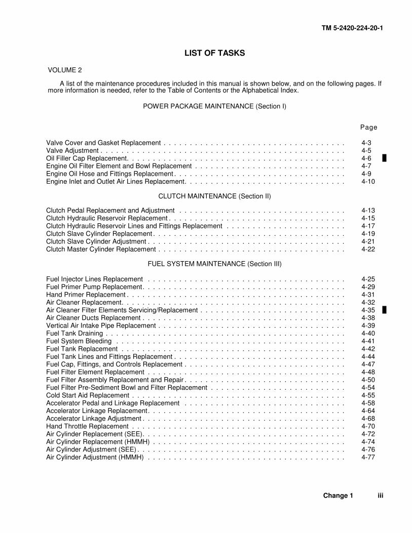
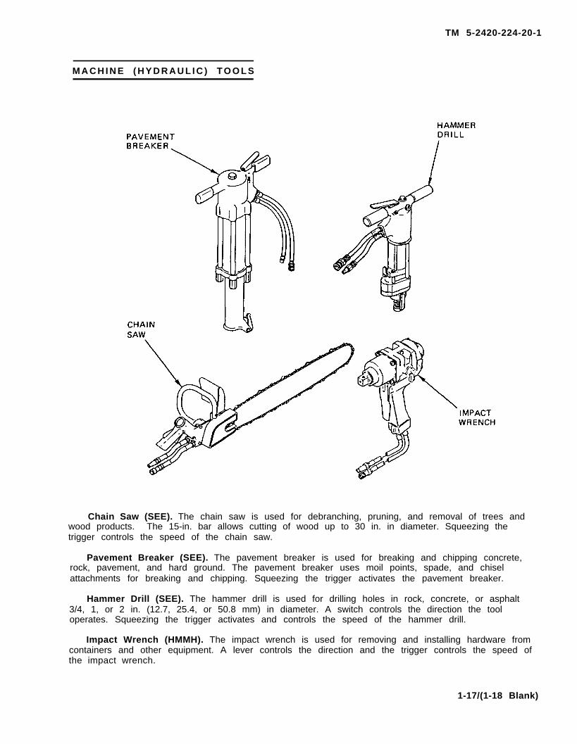
Chain Saw (SEE). The chain saw is used for debranching, pruning, and removal of trees andwood products. The 15-in. bar allows cutting of wood up to 30 in. in diameter. Squeezing thetrigger controls the speed of the chain saw.
Pavement Breaker (SEE). The pavement breaker is used for breaking and chipping concrete,rock, pavement, and hard ground. The pavement breaker uses moil points, spade, and chiselattachments for breaking and chipping. Squeezing the trigger activates the pavement breaker.
Hammer Drill (SEE). The hammer drill is used for drilling holes in rock, concrete, or asphalt3/4, 1, or 2 in. (12.7, 25.4, or 50.8 mm) in diameter. A switch controls the direction the tooloperates. Squeezing the trigger activates and controls the speed of the hammer drill.
Impact Wrench (HMMH). The impact wrench is used for removing and installing hardware fromcontainers and other equipment. A lever controls the direction and the trigger controls the speed ofthe impact wrench.
1-17/(1-18 Blank)
TM 5-2420-224-20-1
CHAPTER 2 SERVICES AND SCHEDULED VEHICLE MAINTENANCE
SCOPE
This chapter contains information you will need to prepare the SEE/HMMMH for daily use and to perform preventive and scheduled maintenance. The following sections are included in this chapter.
Page
Section I Repair Parts; Special Tools; Test, Measurement, and Diagnostic Equipment (TMDE); and Support Equipment ....................................... 2-1
Section II Service Upon Receipt ............................................................................................. 2-2
Section III Preventive Maintenance Checks and Services ...................................................... 2-2
Section IV Lubrication Instructions ........................................................................................... 2-14
Section V Painting and Restenciling Markings ....................................................................... 2-14.24
Section VI General Repair and Cleaning Methods .................................................................. 2-15
Section VII General Hydraulic System Repair Methods ........................................................... 2-32
Section VIII Preparation for Storage or Shipment ...................................................................... 2-36
Section I. REPAIR PARTS; SPECIAL TOOLS; TEST, MEASUREMENT, AND DIAGNOSTIC EQUIPMENT (TMDE); AND SUPPORT EQUIPMENT
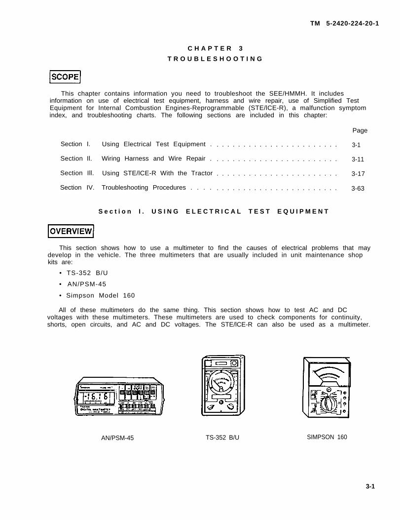
OVERVIEW This section includes information on tools and equipment you need to support the SEE and HMMH tractors.
COMMON TOOLS AND EQUIPMENT
For authorized common tools and equipment, refer to the Modified Table of Organization and Equipment (MTOE) applicable to your unit. Tool kits required for each task in this manual are listed in the Maintenance Allocation Chart (MAC) in Appendix B and on the INITIAL SETUP page of each task.
SPECIAL TOOLS, TMDE, AND SUPPORT EQUIPMENT
Special tools and support equipment required to maintain the SEE/HMMH are listed in the Maintenance Allocation Chart (MAC) Appendix B and on the INITIAL SETUP page of each task. Special tools are also listed in the Repair Parts and Special Tools List (TM 5-2420-224-24P). Tools that are to be fabricated are described and listed in Appendix D of this manual.
REPAIR PARTS
Repair parts are listed and illustrated in the Repair Parts and Special Tools List (TM 5-2420-224-24P) covering the unit maintenance of this equipment.
Change 2 2-1
TM 5-2420-224-20-1
Section II. SERVICE UPON RECEIPT
OVERVIEW This section contains information on what to do when the vehicle is received.
CHECKING EQUIPMENT 1. Inspect the equipment for damage incurred during shipment. If the equipment has been
damaged, report the damage on DD Form 6, Packaging Improvement Report. 2. Check the equipment against the packing slip to see if the shipment is complete. Report all
discrepancies with the instructions of DA PAM 738-750, The Army Maintenance Management System (TAMMS).
3. Check to see whether the equipment has been modified.
INITIAL SERVICES 1. Follow all precautions and instructions on tag DA Form 1397, Processing Record for
Shipment, Storage, and Issue of Vehicle and Spare Engines. 2. Remove all packing and shipping materials, such as tape, tiedowns, protective covers, and
shipping seals. 3. Remove all BII and COEI equipment and store in accordance with TM 5-2420-224-10. 4. If batteries have not been serviced, refer to TM 9-6140-200-14. 5. Service the vehicle in accordance with TM 5-2420-224-10 and Lubrication Instructions,
page 2-14. 6. Refer to TM 5-2420-224-10 and perform functional checks of all major vehicle systems.
Section III. PREVENTIVE MAINTENANCE CHECKS AND SERVICES
OVERVIEW This section details the Preventive Maintenance Checks and Services (PMCS) required for the SEE/HMMH. PMCS is a scheduled, step-by-step inspection and service of the vehicle and vehicle components. Its purpose is to keep the vehicle in good condition and to identify and correct problems before costly and time-consuming repairs are needed.
MAINTENANCE FORMS AND RECORDS Use DA Form 2404, Equipment Inspection and Maintenance Worksheet, to record periodic maintenance services performed and faults corrected. The item number on the DA Form 2404 must be the same as the item number of the PMCS. For information on maintenance forms and records, see DA PAM 738-750.
2-2 Change 2
TM 5-2420-224-20-1
OPERATOR PARTICIPATION
The operator will perform the Operator PMCS (TM 5-2420-224-10) and will also help unit maintenance do the unit PMCS, and perform lubrication in accordance with Lubrication Instructions, page 2-14.
INTERVALS
Unit PMCS should be performed at the intervals shown below:
• Do your (Q) PMCS quarterly (every 3 months).
• Do your (S) PMCS semiannually (every 6 months).
• Do your (A) PMCS annually (once every year).
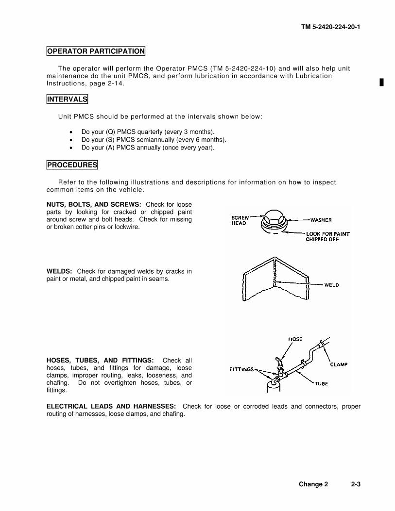
PROCEDURES
Refer to the following illustrations and descriptions for information on how to inspect common items on the vehicle. NUTS, BOLTS, AND SCREWS: Check for loose parts by looking for cracked or chipped paint around screw and bolt heads. Check for missing or broken cotter pins or lockwire. WELDS: Check for damaged welds by cracks in paint or metal, and chipped paint in seams. HOSES, TUBES, AND FITTINGS: Check all hoses, tubes, and fittings for damage, loose clamps, improper routing, leaks, looseness, and chafing. Do not overtighten hoses, tubes, or fittings.
ELECTRICAL LEADS AND HARNESSES: Check for loose or corroded leads and connectors, proper routing of harnesses, loose clamps, and chafing.
Change 2 2-3
TM 5-2420-224-20-1
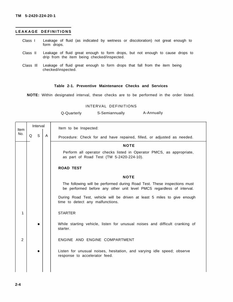
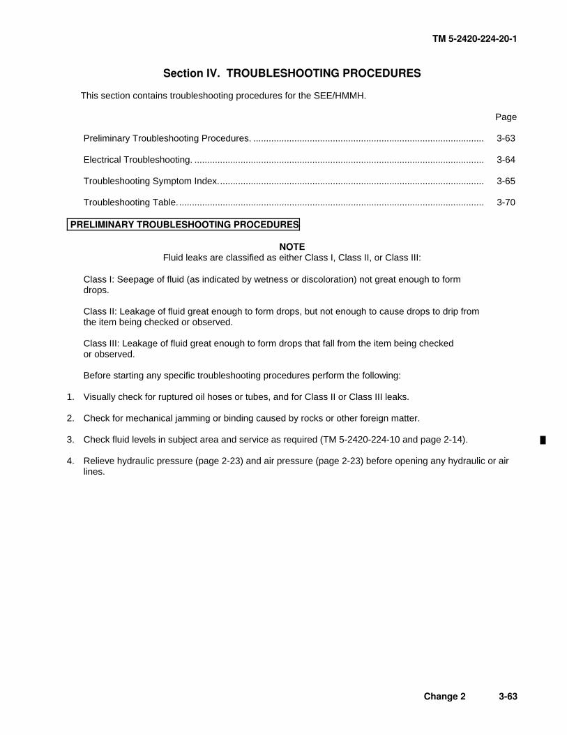
L E A K A G E D E F I N I T I O N S
Class I
Class II
Class Ill
Leakage of fluid (as indicated by wetness or discoloration) not great enough toform drops.
Leakage of fluid great enough to form drops, but not enough to cause drops todrip from the item being checked/inspected.
Leakage of fluid great enough to form drops that fall from the item beingchecked/inspected.
Table 2-1. Preventive Maintenance Checks and Services
NOTE: Within designated interval, these checks are to be performed in the order listed.
INTERVAL DEFINITIONS
Q-Quarterly S-Semiannually A-Annually
ItemNo.
1
2
2-4
Interval
Q S A
Item to be Inspected:
Procedure: Check for and have repaired, filled, or adjusted as needed.
NOTE
Perform all operator checks listed in Operator PMCS, as appropriate,as part of Road Test (TM 5-2420-224-10).
ROAD TEST
NOTE
The following will be performed during Road Test. These inspections mustbe performed before any other unit level PMCS regardless of interval.
During Road Test, vehicle will be driven at least 5 miles to give enoughtime to detect any malfunctions.
STARTER
While starting vehicle, listen for unusual noises and difficult cranking ofstarter.
ENGINE AND ENGINE COMPARTMENT
Listen for unusual noises, hesitation, and varying idle speed; observeresponse to accelerator feed.
TM 5-2420-224-20-1
Change 1 2-5
Table 2-1. Preventive Maintenance Checks and Services (Cont)
NOTE: Within designated interval, these checks are to be performed in the order listed.
Procedure: Check for and have repaired, filled, or adjusted as needed.
3
4
5
6
7
! ! !
!
!
! !
!
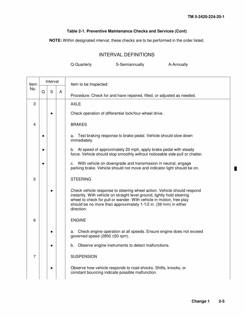
AXLE
Check operation of differential Iock/four-wheel drive.
BRAKES
a. Test braking response to brake pedal. Vehicle should slow down immediately.
b. At speed of approximately 20 mph, apply brake pedal with steady force. Vehicle should stop smoothly without noticeable side-pull or chatter.
c. With vehicle on downgrade and transmission in neutral, engage parking brake. Vehicle should not move and indicator light should be on.
STEERING
Check vehicle response to steering wheel action. Vehicle should respond instantly. With vehicle on straight level ground, lightly hold steering wheel to check for pull or wander. With vehicle in motion, free play should be no more than approximately ∀-∀/2 in. (39 mm) in either direction.
ENGINE
a. Check engine operation at all speeds. Ensure engine does not exceed governed speed (2850 ±50 rpm).
b. Observe engine instruments to detect malfunctions.
SUSPENSION
Observe how vehicle responds to road shocks. Shifts, knocks, or constant bouncing indicate possible malfunction.
TM 5-2420-224-20-1
2-6
Table 2-1. Preventive Maintenance Checks and Services (Cont)
NOTE: Within designated interval, these checks are to be performed in the order listed.
Procedure: Check for and have repaired, filled, or adjusted as needed.
8
9
!
!
!
AFTER ROAD TEST
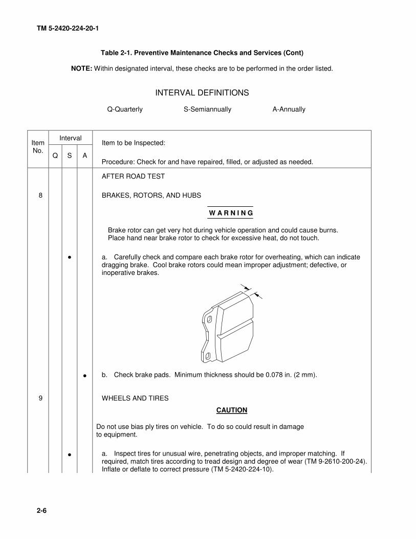
BRAKES, ROTORS, AND HUBS
W A R N I N G
Brake rotor can get very hot during vehicle operation and could cause burns. Place hand near brake rotor to check for excessive heat, do not touch.
a. Carefully check and compare each brake rotor for overheating, which can indicate dragging brake. Cool brake rotors could mean improper adjustment; defective, or inoperative brakes.
b. Check brake pads. Minimum thickness should be 0.078 in. (2 mm).
WHEELS AND TIRES
CAUTION
Do not use bias ply tires on vehicle. To do so could result in damage to equipment.
a. Inspect tires for unusual wire, penetrating objects, and improper matching. If required, match tires according to tread design and degree of wear (TM 9-26∀0-200-24). Inflate or deflate to correct pressure (TM 5-2420-224-∀0).
TM 5-2420-224-20-1
Change 1 2-7
Table 2-1. Preventive Maintenance Checks and Services (Cont)
NOTE: Within designated interval, these checks are to be performed in the order listed.
Procedure: Check for and have repaired, filled, or adjusted as needed.
∀0
∀∀
∀2
∀3
∀4
∀5
!
!
!
!
!
! ! !
!
WHEELS AND TIRES (CONT)
b. Check lug nuts for proper torque of 260 Ib-ft (350 N.m).
AIR BRAKE SYSTEM
Check brake system components for leaks and damage. Check all brake hoses for wear, pinching, or interference. If any of these conditions are found, replace or reposition hose. Replacement is mandatory for any hose worn or chafed before vehicle use. Replacement is mandatory for any hose that is leaking or has bulges.
TRANSMISSION
Check transmission for leaks, loose bolts, and obvious damage.
FRONT AXLE
Check for loose screws and missing or damaged mounting hardware.
REAR AXLES
Check for loose screws and missing or damaged mounting hardware.
SUSPENSION
a. Check coil springs for cracks or breaks.
b. Check torque of coil spring mounting bolts. Torque should be ∀03 Ib-ft (∀40 N.m).
c. Change oil and filter in front suspension lockout system (HMMH).
FRAME AND CROSSMEMBERS
a. Inspect frame and side rails for cracks, breaks, bends, wear, deterioration, and loose bolts.
TM 5-2420-224-20-1
2-8
Table 2-1. Preventive Maintenance Checks and Services (Cont)
NOTE: Within designated interval, these checks are to be performed in the order listed.
Procedure: Check for and have repaired, filled, or adjusted as needed.
∀6
!
!
!
FRAME AND CROSSMEMBERS (CONT)
b. Inspect crossmembers for weld breaks.
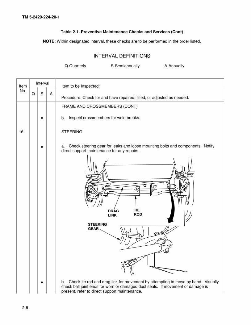
STEERING
a. Check steering gear for leaks and loose mounting bolts and components. Notify direct support maintenance for any repairs.
b. Check tie rod and drag link for movement by attempting to move by hand. Visually check ball joint ends for worn or damaged dust seals. If movement or damage is present, refer to direct support maintenance.
TM 5-2420-224-20-1
Table 2-1. Preventive Maintenance Checks and Services (Cont)
NOTE: Within designated interval, these checks are to be performed in the order listed.
INTERVAL DEFINITIONS
Q-Quarterly S-Semiannually A-Annually
Interval
Item Item to be Inspected:
No. Q S A Procedure: Check for and have repaired, filled, or adjusted as needed.
STEERING (CONT)
• c. Check all hydraulic steering lines, hoses, and tubes for loose fittings, rubbing, chafing, cracks, bends, breaks, and leaks. Tighten if loose and replace or repair hoses or lines that are damaged.
• d. Inspect power steering reservoir for leaks and loose hoses.
• e. Inspect power steering pump for leaks, cracks, or damage.
• f. Replace steering system filter (page 4-359).
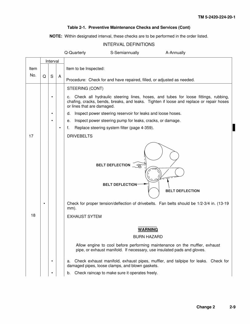
17 DRIVEBELTS
• Check for proper tension/deflection of drivebelts. Fan belts should be 1/2-3/4 in. (13-19 mm).
18 EXHAUST SYTEM
WARNING
BURN HAZARD
Allow engine to cool before performing maintenance on the muffler, exhaust pipe, or exhaust manifold. If necessary, use insulated pads and gloves.
• a. Check exhaust manifold, exhaust pipes, muffler, and tailpipe for leaks. Check for damaged pipes, loose clamps, and blown gaskets.
• b. Check raincap to make sure it operates freely.
Change 2 2-9
TM 5-2420-224-20-1
Table 2-1. Preventive Maintenance Checks and Services (Cont)
NOTE: Within designated interval, these checks are to be performed in the order listed.
INTERVAL DEFINITIONS
Q-Quarterly S-Semiannually A-Annually
Interval
Item Item to be Inspected:
No. Q S A Procedure: Check for and have repaired, filled, or adjusted as needed.
19 FUEL SYSTEM
• a. Inspect fuel lines, fuel tank, and fuel system components for leaks and damage.
• b. Replace fuel filters (page 4-50).
20 COOLING SYSTEM
NOTE
Refer to TB 750-651 for cooling system service.
• a. Remove debris from cooling fins and check for bent fins.
• b. Inspect radiator core for leaks.
• c. Check hoses, cap, gaskets, rubber isolator mounts, and fan shroud mounting for cracks and leaks.
• d. Inspect water pump for leaks.
21 AIR INTAKE SYSTEM
WARNING
If NBC exposure is suspected, all filter media should be handled by personnel wearing protective equipment. Consult your unit NBC Officer or NBC NCO for appropriate handling or disposal instructions.
• a. Check air cleaner, hoses, and air cleaner for proper installation, cracks, breaks, or loose connections that could let unfiltered air into air intake system.
• b. Check air intake screen for debris and damage.
• c. Check for dirty air filter elements.
• d. Clean/replace primary (outer) filter element (page 4-35). Never clean safety (inner) element.
2-10 Change 1
TM 5-2420-224-20-1
Table 2-1. Preventive Maintenance Checks and Services (Cont)
NOTE: Within designated interval, these checks are to be performed in the order listed.
INTERVAL DEFINITIONS
Q-Quarterly S-Semiannually A-Annually
Interval
Item Item to be Inspected:
No. Q S A Procedure: Check for and have repaired, filled, or adjusted as needed.
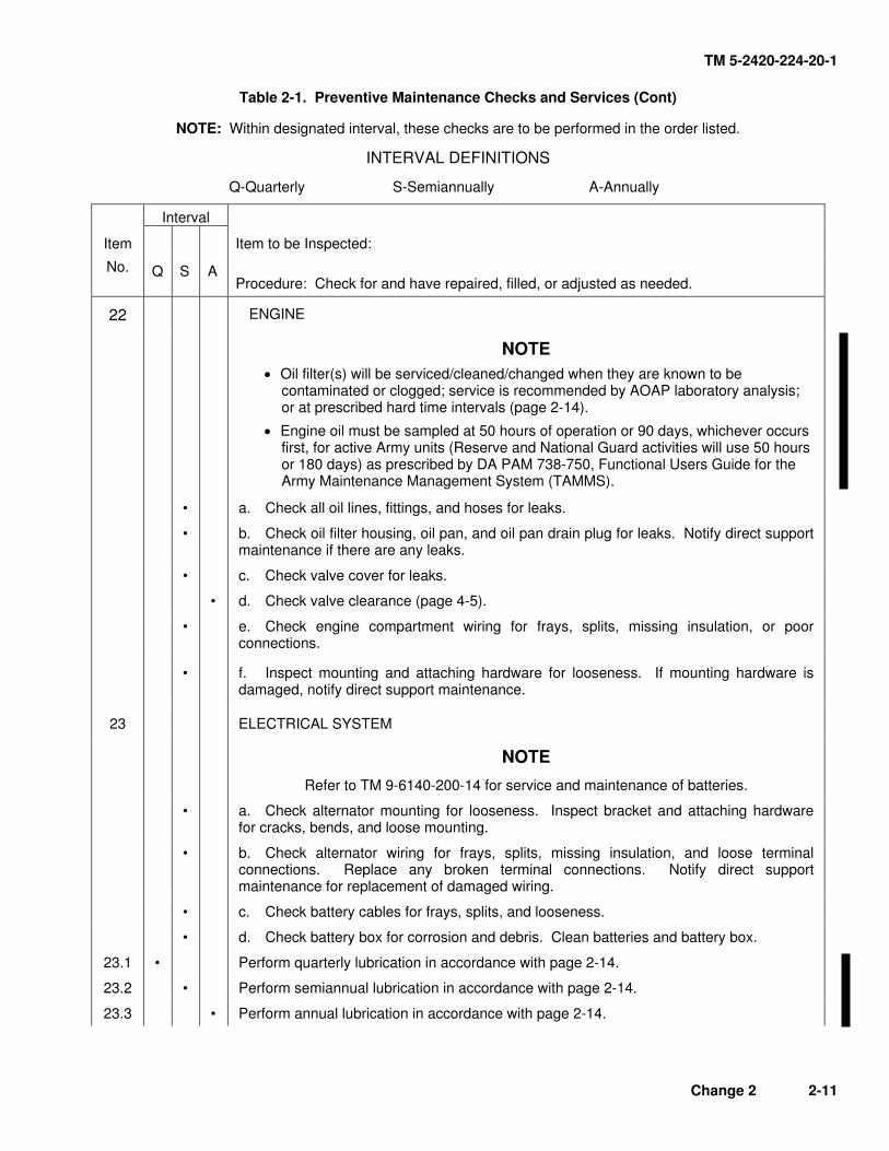
22 ENGINE
NOTE
• Oil filter(s) will be serviced/cleaned/changed when they are known to be contaminated or clogged; service is recommended by AOAP laboratory analysis; or at prescribed hard time intervals (page 2-14).
• Engine oil must be sampled at 50 hours of operation or 90 days, whichever occurs first, for active Army units (Reserve and National Guard activities will use 50 hours or 180 days) as prescribed by DA PAM 738-750, Functional Users Guide for the Army Maintenance Management System (TAMMS).
• a. Check all oil lines, fittings, and hoses for leaks.
• b. Check oil filter housing, oil pan, and oil pan drain plug for leaks. Notify direct support maintenance if there are any leaks.
• c. Check valve cover for leaks.
• d. Check valve clearance (page 4-5).
• e. Check engine compartment wiring for frays, splits, missing insulation, or poor connections.
• f. Inspect mounting and attaching hardware for looseness. If mounting hardware is damaged, notify direct support maintenance.
23 ELECTRICAL SYSTEM
NOTE
Refer to TM 9-6140-200-14 for service and maintenance of batteries.
• a. Check alternator mounting for looseness. Inspect bracket and attaching hardware for cracks, bends, and loose mounting.
• b. Check alternator wiring for frays, splits, missing insulation, and loose terminal connections. Replace any broken terminal connections. Notify direct support maintenance for replacement of damaged wiring.
• c. Check battery cables for frays, splits, and looseness.
• d. Check battery box for corrosion and debris. Clean batteries and battery box.
23.1 • Perform quarterly lubrication in accordance with page 2-14.
23.2 • Perform semiannual lubrication in accordance with page 2-14.
23.3 • Perform annual lubrication in accordance with page 2-14.
Change 2 2-11
TM 5-2420-224-20-1
Table 2-1. Preventive Maintenance Checks and Services (Cont)
NOTE: Within designated interval, these checks are to be performed in the order listed.
INTERVAL DEFINITIONS
Q-Quarterly S-Semiannually A-Annually
Interval
Item Item to be Inspected:
No. Q S A Procedure: Check for and have repaired, filled, or adjusted as needed.
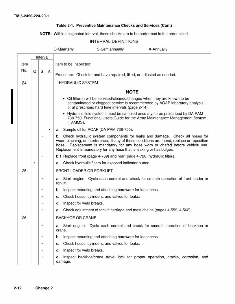
24 HYDRAULIC SYSTEM
NOTE
• Oil filter(s) will be serviced/cleaned/changed when they are known to be contaminated or clogged; service is recommended by AOAP laboratory analysis; or at prescribed hard time intervals (page 2-14).
• Hydraulic fluid systems must be sampled once a year as prescribed by DA PAM 738-750, Functional Users Guide for the Army Maintenance Management System (TAMMS).
• a. Sample oil for AOAP (DA PAM 738-750).
• b. Check hydraulic system components for leaks and damage. Check all hoses for wear, pinching, or interference. If any of these conditions are found, replace or reposition hose. Replacement is mandatory for any hose worn or chafed before vehicle use. Replacement is mandatory for any hose that is leaking or has bulges.
• b.1 Replace front (page 4-709) and rear (page 4-720) hydraulic filters.
• c. Check hydraulic filters for exposed indicator button.
25 FRONT LOADER OR FORKLIFT
• a. Start engine. Cycle each control and check for smooth operation of front loader or forklift.
• b. Inspect mounting and attaching hardware for looseness.
• c. Check hoses, cylinders, and valves for leaks.
• d. Inspect for weld breaks.
• e. Check adjustment of forklift carriage and mast chains (pages 4-559, 4-562).
26 BACKHOE OR CRANE
• a. Start engine. Cycle each control and check for smooth operation of backhoe or crane.
• b. Inspect mounting and attaching hardware for looseness.
• c. Check hoses, cylinders, and valves for leaks.
• d. Inspect for weld breaks.
• e. Inspect backhoe/crane travel lock for proper operation, cracks, corrosion, and damage.
2-12 Change 2
TM 5-2420-224-20-1
Table 2-1. Preventive Maintenance Checks and Services (Cont)
NOTE: Within designated interval, these checks are to be performed in the order listed.
INTERVAL DEFINITIONS
Q-Quarterly S-Semiannually A-Annually
Interval
Item Item to be Inspected:
No. Q S A Procedure: Check for and have repaired, filled, or adjusted as needed.
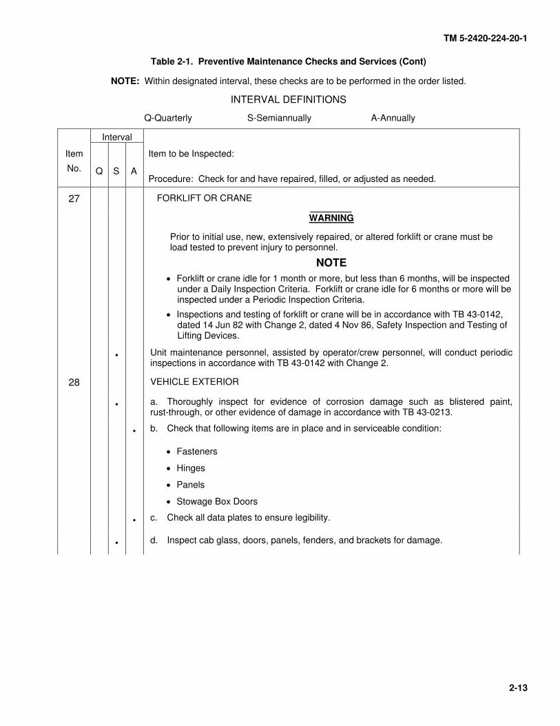
27 FORKLIFT OR CRANE
WARNING
Prior to initial use, new, extensively repaired, or altered forklift or crane must be load tested to prevent injury to personnel.
NOTE
• Forklift or crane idle for 1 month or more, but less than 6 months, will be inspected under a Daily Inspection Criteria. Forklift or crane idle for 6 months or more will be inspected under a Periodic Inspection Criteria.
• Inspections and testing of forklift or crane will be in accordance with TB 43-0142, dated 14 Jun 82 with Change 2, dated 4 Nov 86, Safety Inspection and Testing of Lifting Devices.
• Unit maintenance personnel, assisted by operator/crew personnel, will conduct periodic inspections in accordance with TB 43-0142 with Change 2.
28 VEHICLE EXTERIOR
• a. Thoroughly inspect for evidence of corrosion damage such as blistered paint, rust-through, or other evidence of damage in accordance with TB 43-0213.
• b. Check that following items are in place and in serviceable condition:
• Fasteners
• Hinges
• Panels
• Stowage Box Doors
• c. Check all data plates to ensure legibility.
• d. Inspect cab glass, doors, panels, fenders, and brackets for damage.
2-13
TM 5-2420-224-20-1
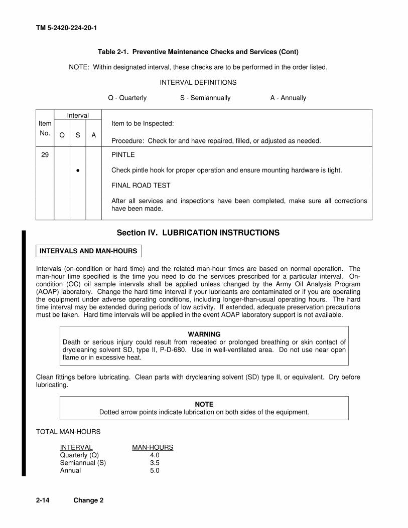
Table 2-1. Preventive Maintenance Checks and Services (Cont)
NOTE: Within designated interval, these checks are to be performed in the order listed.
INTERVAL DEFINITIONS Q - Quarterly S - Semiannually A - Annually
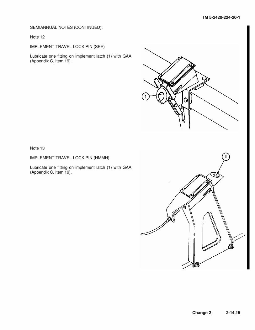
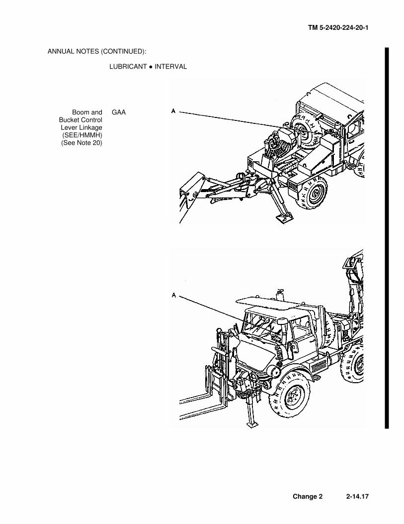
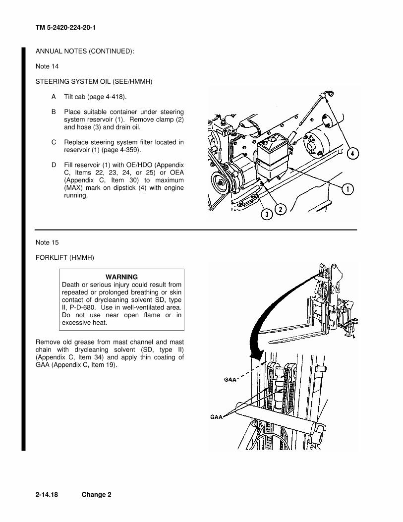
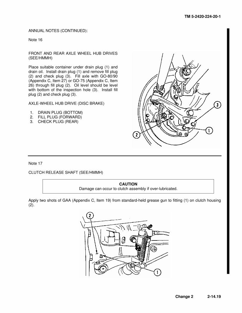
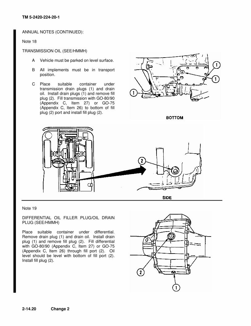
Interval Item Item to be Inspected:
No. Q S A Procedure: Check for and have repaired, filled, or adjusted as needed.
29 PINTLE Ɣ Check pintle hook for proper operation and ensure mounting hardware is tight. FINAL ROAD TEST After all services and inspections have been completed, make sure all corrections
have been made.
Section IV. LUBRICATION INSTRUCTIONS
INTERVALS AND MAN-HOURS
Intervals (on-condition or hard time) and the related man-hour times are based on normal operation. The man-hour time specified is the time you need to do the services prescribed for a particular interval. On-condition (OC) oil sample intervals shall be applied unless changed by the Army Oil Analysis Program (AOAP) laboratory. Change the hard time interval if your lubricants are contaminated or if you are operating the equipment under adverse operating conditions, including longer-than-usual operating hours. The hard time interval may be extended during periods of low activity. If extended, adequate preservation precautions must be taken. Hard time intervals will be applied in the event AOAP laboratory support is not available.
WARNING Death or serious injury could result from repeated or prolonged breathing or skin contact of drycleaning solvent SD, type II, P-D-680. Use in well-ventilated area. Do not use near open flame or in excessive heat.
Clean fittings before lubricating. Clean parts with drycleaning solvent (SD) type II, or equivalent. Dry before lubricating.
NOTE Dotted arrow points indicate lubrication on both sides of the equipment.
TOTAL MAN-HOURS
INTERVAL MAN-HOURS Quarterly (Q) 4.0 Semiannual (S) 3.5 Annual 5.0
2-14 Change 2
TM 5-2420-224-20-1
LUBRICANTS
KEY
EXPECTED TEMPERATURES
LUBRICANTS CAPACITIES Above +32 °F(Above 0 °C)
+40° to -10 °F(+4° to -26 °C)
0° to -65 °F (-17° to -53 °C)
INTERVALS
OE/HDO (MIL-L-2104)
LUBRICATING OIL, Internal Combustion Engine, Tactical Service
Q - Quarterly/ 250 hours S - Semiannually/ 500 hours A - Annually/ 1000 hours OC - On-condition
For
Arc
tic o
pera
tion r
efe
r to
TM
9-2
07.
Change 2 2-14.1
TM 5-2420-224-20-1
OIL ANALYSIS PROGRAM SAMPLING PROCEDURES
The engine oil sampling valve is located on the end of the oil filter located on the right side of the engine. When a lubrication note specifies that an oil sample must be taken, use the following procedures: A Ensure that oil to be sampled is at its normal operating temperature (TM 5-2420-224-10). B Open valve (1) and pump approximately two ounces of oil into suitable container, by pumping
plunger (2). Discard this oil. This will remove waste impurities from oil filter. C Place sample bottle (TB 43-0210) under valve (1) and fill sample bottle to approximately 1/2 in. (1.3
cm) below neck of bottle. Close valve (1) and check for leaks. D Send oil sample to AOAP laboratory.
2-14.2 Change 2
TM 5-2420-224-20-1
QUARTERLY NOTES: LUBRICANT Ɣ INTERVAL
Axle Drive and Wheel Hub
Reduction of Front and Rear Axle
(SEE/HMMH) (See Note 1)
GO
Forklift (HMMH) (See Note 2)
Front and Rear Differentials
(SEE/HMMH) (See Note 3)
GAA GO
Change 2 2-14.3
TM 5-2420-224-20-1
QUARTERLY NOTES (CONTINUED): LUBRICANT Ɣ INTERVAL
King Pins (SEE/HMMH) (See Note 4)
Transmission (SEE/HMMH) (See Note 5)
Front and Rear Thrust Ball Joint
(SEE/HMMH) (See Note 6)
Hand Brake Lever
(SEE/HMMH) (See Note 7)
Pintle Hook (SEE/HMMH) (See Note 8)
GAA GO GAA GAA GAA
2-14.4 Change 2
TM 5-2420-224-20-1
QUARTERLY NOTES (CONTINUED): Note 1 AXLE DRIVE AND WHEEL HUB REDUCTION OF FRONT AND REAR AXLE (SEE/HMMH)
WARNING Place vehicle in two-wheel drive before checking oil level. Oil is under pressure when in four-wheel drive position and could cause serious injury to eyes when removing inspection plug.
Remove inspection plug (1) in each axle and check oil level. Oil should be level with the bottom of the oil inspection hole. Add GO-80/90 (Appendix C, Item 27) or GO-75 (Appendix C, Item 26) as required. AXLE-WHEEL HUB DRIVE (DISC BRAKE) 1. CHECK PLUG (REAR) 2. FILL PLUG (FORWARD) 3. DRAIN PLUG (BOTTOM)
Note 2 FORKLIFT (HMMH) Lubricate two fittings on rotator bearing every 300 hours with GAA (Appendix C, Item 19).
Change 2 2-14.5
TM 5-2420-224-20-1
QUARTERLY NOTES (CONTINUED): Note 3 FRONT AND REAR DIFFERENTIALS (SEE/HMMH)
WARNING Place vehicle in two-wheel drive before checking oil level. Oil is under pressure when in four-wheel drive position and could cause serious injury to eyes when removing inspection plug.
Remove inspection plug (1) in each differential and check oil level. Oil should be level with the bottom of the oil inspection hole. Add GO-80/90 (Appendix C, Item 27) or GO-75 (Appendix C, Item 26) as required. AXLE DRIVE 1. FILL AND CHECK PLUG 2. DRAIN PLUG
Note 4 KING PINS (SEE/HMMH) Lubricate four king pins (1) with GAA (Appendix C, Item 19).
2-14.6 Change 2
TM 5-2420-224-20-1
QUARTERLY NOTES (CONTINUED): Note 5 TRANSMISSION (SEE/HMMH) Check transmission oil level by removing fill plug (1). Oil should be level with the bottom of the oil inspection hole. Add GO-80/90 (Appendix C, Item 27) or GO-75 (Appendix C, Item 26) as required.
Note 6 FRONT AND REAR THRUST BALL JOINT (SEE/HMMH)
CAUTION Damage to protective rubber bellows will occur if over-lubricated.
Lubricate ball joints (1) with five shots of GAA (Appendix C, Item 19) from a standard hand-held grease gun.
Change 2 2-14.7
TM 5-2420-224-20-1
QUARTERLY NOTES (CONTINUED): QUARTERLY NOTES (CONTINUED): Note 7 Note 7 HAND BRAKE LEVER (SEE/HMMH) HAND BRAKE LEVER (SEE/HMMH) Lubricate hand brake lever fitting (1) above rear axle with GAA (Appendix C, Item 19). Lubricate hand brake lever fitting (1) above rear axle with GAA (Appendix C, Item 19).
Note 8 Note 8 PINTLE HOOK (SEE/HMMH) PINTLE HOOK (SEE/HMMH) Lubricate three fittings (1) on pintle hook (2) with GAA (Appendix C, Item 19). Lubricate three fittings (1) on pintle hook (2) with GAA (Appendix C, Item 19).
TM 5-2420-224-20-1
2-14.8 Change 2
2-14.8 Change 2
TM 5-2420-224-20-1
QUARTERLY NOTES (CONTINUED):
OIL CAN POINTS
Lubricate with PL-M (Appendix C, Item 43) or PL-S (Appendix C, Item 44).
SEMIANNUAL NOTES (CONTINUED): Note 10 FRONT SUSPENSION LOCKOUT SYSTEM (HMMH) A Remove and replace oil filter (1) (page 4-507). B Remove reservoir (2) from manifold (3) and drain oil (page 4-511). C Install reservoir (2) to manifold (3) and service with OE/HDO (Appendix C, Items 22, 23, 24, or 25)
or OEA (Appendix C, Item 30). Oil should be at the MAX mark on reservoir (page 4-511).
Change 2 2-14.13
TM 5-2420-224-20-1
2-14.14 Change 2
SEMIANNUAL NOTES (CONTINUED): Note 11 HYDRAULIC TANKS, FRONT AND REAR (SEE/HMMH) A Place suitable container under drain plug
(1) and drain oil. Install drain plug. B Replace hydraulic filter (2) at top of tank
(front, page 4-709; rear, page 4-720). C Fill hydraulic tank with OE/HDO
(Appendix C, Items 22, 23, 24, or 25) or OEA (Appendix C, Item 30) with implements in travel position.
D Check sight gage to ensure proper oil
level is achieved (TM 5-2420-224-10).
TM 5-2420-224-20-1
SEMIANNUAL NOTES (CONTINUED): Note 12 IMPLEMENT TRAVEL LOCK PIN (SEE) Lubricate one fitting on implement latch (1) with GAA (Appendix C, Item 19).
Note 13 IMPLEMENT TRAVEL LOCK PIN (HMMH) Lubricate one fitting on implement latch (1) with GAA (Appendix C, Item 19).
Change 2 2-14.15
TM 5-2420-224-20-1
ANNUAL NOTES: LUBRICANT Ɣ INTERVAL
Steering System Oil
(SEE/HMMH) (See Note 14)
Forklift (HMMH) (See Note 15)
OE/HDO, OEA GAA
Front and Rear Axle
Wheel Hub Drives
(SEE/HMMH) (See Note 16)
Clutch Release Shaft
(SEE/HMMH) (See Note 17)
Transmission Oil (SEE/HMMH) (See Note 18)
Differential Oil Filler Plug/Oil
Drain Plug (SEE/HMMH) (See Note 19)
GO GAA GO GO
2-14.16 Change 2
TM 5-2420-224-20-1
Change 2 2-14.17
ANNUAL NOTES (CONTINUED): LUBRICANT Ɣ INTERVAL
Boom and Bucket Control Lever Linkage (SEE/HMMH) (See Note 20)
GAA
TM 5-2420-224-20-1
ANNUAL NOTES (CONTINUED): Note 14 STEERING SYSTEM OIL (SEE/HMMH) A Tilt cab (page 4-418). B Place suitable container under steering
system reservoir (1). Remove clamp (2) and hose (3) and drain oil.
C Replace steering system filter located in
reservoir (1) (page 4-359). D Fill reservoir (1) with OE/HDO (Appendix
C, Items 22, 23, 24, or 25) or OEA (Appendix C, Item 30) to maximum (MAX) mark on dipstick (4) with engine running.
Note 15 FORKLIFT (HMMH)
WARNING Death or serious injury could result from repeated or prolonged breathing or skin contact of drycleaning solvent SD, type II, P-D-680. Use in well-ventilated area. Do not use near open flame or in excessive heat.
Remove old grease from mast channel and mast chain with drycleaning solvent (SD, type II) (Appendix C, Item 34) and apply thin coating of GAA (Appendix C, Item 19).
2-14.18 Change 2
TM 5-2420-224-20-1
ANNUAL NOTES (CONTINUED): Note 16 FRONT AND REAR AXLE WHEEL HUB DRIVES (SEE/HMMH) Place suitable container under drain plug (1) and drain oil. Install drain plug (1) and remove fill plug (2) and check plug (3). Fill axle with GO-80/90 (Appendix C, Item 27) or GO-75 (Appendix C, Item 26) through fill plug (2). Oil level should be level with bottom of the inspection hole (3). Install fill plug (2) and check plug (3). AXLE-WHEEL HUB DRIVE (DISC BRAKE) 1. DRAIN PLUG (BOTTOM) 2. FILL PLUG (FORWARD) 3. CHECK PLUG (REAR)
Note 17 CLUTCH RELEASE SHAFT (SEE/HMMH)
CAUTION Damage can occur to clutch assembly if over-lubricated.
Apply two shots of GAA (Appendix C, Item 19) from standard-held grease gun to fitting (1) on clutch housing (2).
Change 2 2-14.19
TM 5-2420-224-20-1
ANNUAL NOTES (CONTINUED): Note 18 TRANSMISSION OIL (SEE/HMMH) A Vehicle must be parked on level surface. B All implements must be in transport
position. C Place suitable container under
transmission drain plugs (1) and drain oil. Install drain plugs (1) and remove fill plug (2). Fill transmission with GO-80/90 (Appendix C, Item 27) or GO-75 (Appendix C, Item 26) to bottom of fill plug (2) port and install fill plug (2).
Note 19 DIFFERENTIAL OIL FILLER PLUG/OIL DRAIN PLUG (SEE/HMMH) Place suitable container under differential. Remove drain plug (1) and drain oil. Install drain plug (1) and remove fill plug (2). Fill differential with GO-80/90 (Appendix C, Item 27) or GO-75 (Appendix C, Item 26) through fill port (2). Oil level should be level with bottom of fill port (2). Install fill plug (2).
2-14.20 Change 2
TM 5-2420-224-20-1
ANNUAL NOTES (CONTINUED): Note 20 BOOM AND BUCKET CONTROL LEVER LINKAGE (SEE/HMMH) A Lubricate one fitting with GAA (Appendix C, Item 19) inside cab at boom and bucket control lever
linkage (1). B Lubricate one fitting with GAA (Appendix C, Item 19) outside cab at boom and bucket control lever
WARNING Hot oil causes burns and serious injury. Use care when checking or draining hot oil.
NOTE Drain oil when notified by Army Oil Analysis Program (AOAP) laboratory. Unless notified by AOAP, engine oil must be changed quarterly.
A Remove inside engine hood (page
4-389). B Run engine until warm; stop engine.
Place suitable container under engine. Remove drain plug (1) and drain oil. Install drain plug (1).
C Remove and discard oil filter element (2)
(page 4-7). Clean filter base. Apply thin coating of clean oil to gasket on base of new filter element (2) and install on engine (page 4-7).
D Remove filler cap (3) and fill engine with
OE/HDO or OEA until dipstick (4) indicates maximum (MAX) level. Remove filler plug (5) and fill filter bowl/canister with OE/HDO (Appendix C, Items 22, 23, 24, or 25) or OEA (Appendix C, Item 30).
E Start engine and check for oil leaks. F Check oil level after engine has been
shut down.
TM 5-2420-224-20-1
Section V. PAINTING AND RESTENCILING MARKINGS
GENERAL
Complete painting of the vehicle is authorized for and done by direct support maintenance or higher. Spot painting and restenciling vehicle markings are done by unit maintenance. Instructions for material preparation and painting are given in TM 43-0139, Painting Instructions for Field Use. VEHICLE INTERIOR Prepare surface in accordance with TM 43-0139 and MIL-STD-193. VEHICLE EXTERIOR Prepare surface in accordance with TM 43-0139 and MIL-STD-193. Coat surface with color forest green, black, or brown, specification MIL-C-46168. NONSKID AREAS Deck covering compound, non-slip, type III, MIL-D-23003 will be used to coat deck areas where personnel walk. RESTENCILING MARKINGS All stenciled markings on the SEE/HMMH are black. Use paint conforming to specification MIL-C-46168.
2-14.24 Change 2
S e c t i o n V I . G E N E R A L R E P A I R A N D C L E A N I N G M E T H O D
TM 5-2420-224-20-1
This section describes general maintenance instructions that apply to all parts of this manual.To avoid repetition, these procedures will not be described in specific maintenance sections.
GENERAL REMOVAL INSTRUCTION S
1.
2.
3.
4.
5.
6.
Work Required. Remove only those parts needing repair or replacement. Do not disassemble acomponent any further than needed.
Preparation. Before removing any part of the electrical, hydraulic, or air systems, make certainsystem is not energized or pressurized. Disconnect battery cables. Relieve all pressure from airsystem. Make sure brakes are locked and that all controls are in OFF position before starlingany removal procedure.
Removal. Make sure there is enough clearance to remove part. Disassemble adjacent parts asneeded to provide working clearance.
Lifting. Always use chain hoist, jack, or other aid when lifting heavy parts. Make certain loadlimit of lifting device exceeds weight being lifted. Position and rig lifting device beforedisconnecting part for removal.
Identification. Tag or mark all similar parts, such as electrical leads, before disconnecting andremoving such parts. This will make proper assembly easier. Be sure to identify mating ends ofelectric lines, hydraulic lines, and air tubes as they are disconnected.
Position of Valves. Before removing valve handles, mark or diagram their positions when openand closed. This will help during assembly.
G E N E R A L D I S A S S E M B L Y l N S T R U C T I O N S
1.
2.
3.
4.
5.
Cleanliness. Work area must be kept as clean as possible. This will prevent injury orcontamination of internal parts. This is especially true for valves, cylinders, and other hydraulicor air system parts.
Expendable Parts. As indicated in this manual, all gaskets, packings, and seals removed duringrepair must be discarded and replaced with new parts. These items are usually damaged duringremoval. In the same way, all Iockwire, cotter pins, and like items must be replaced at time ofassembly.
Removing Seals. When removing gaskets, packings, or seals, do not use any metal tool thatwill scratch the surfaces next to these items.
Disassembly. Before disassembly of any item, study the illustration carefully. Note relationshipof internal parts. Knowing details of a component will speed up disassembly and assembly andwill help avoid mistakes.
Parts Protection. To prevent moisture and dirt from entering open housings, lines, and otheropenings, apply protective caps and plugs as soon as possible after disassembly. Wrap allremoved parts in clean paper or coat parts with solid lubricant preservative.
Change 2 2-15
TM 5-2420-224-20-1
G E N E R A L C L E A N I N G I N S T R U C T I O N S
1.
2.
3.
4.
5.
W A R N I N G
Dryc lean ing so lven t P -D-680 i s tox ic and f lammab le . Wear p ro tec t i vegoggles and gloves and use only in well-ventilated area. Avoid contact withskin, eyes, and clothes and do not breathe vapors. Do not use near openflame or excessive heat. Flash point is 100° -1380F (38°-50°C). If youbecome dizzy while using drycleaning solvent, get fresh air immediately andget medical aid. If contact with eyes is made, wash your eyes with waterand get medical aid immediately.
Never use gasoline to clean parts. Gasoline is highly flammable. Seriouspersonal injury could result if fuel ignites during cleaning.
C A U T I O N
• Petroleum solvents may damage parts that are in contact wi th hydraul icfluids.
• To prevent damage to equipment, do not clean tires, lubricant seals, rubberhoses, or electrical components with solvent mixture.
Cleaning Solvents. Use only approved cleaning solvents to clean parts. Drycleaning solventSD-2 (P-D-680) is commonly used. Always work in a well-ventilated area.
W A R N I N GTo prevent injury, compressed air used for cleaning and drying purposes willnot exceed 30 psi (207 kPa). Use only wi th ef fect ive chip guarding andpersonal protective equipment (goggles/shield, gloves, etc.).
Removing Deposits. After soaking parts in solvent, wash away deposits by flushing or spraying.Where necessary, brush with a soft-bristle brush moistened in solvent. Use compressed air todry all parts, except bearings. Bearings must be allowed to air dry.
Tools. Do not use abrasive wheels, or compounds in cleaning parts, unless called for indetailed instructions. These procedures may weaken a highly stressed part.
Ball and Roller Bearings. When cleaning ball or roller bearings, place them in a basket andsuspend them in a container of drycleaning solvent. If needed, use a brush to remove bearingbefore solid particles are removed to prevent damaging races and balls. When bearings havebeen cleaned, coat them lightly with lubricating oil to remove solvent. Refer to TM 9-214 foradditional instructions on cleaning bearings.
Rubber Parts. Do not clean rubber parts in drycleaning solvent. Clean by washing with a mildsolution of soap and water. Wipe with a clean, dry, lint-free cloth.
2-16
TM 5-2420-224-20-1
W A R N I N GSteam cleaning creates hazardous noise levels and severe burn potent ia l .Eye, skin, and ear protection are required.
6. Exterior Parts. Steam clean all exterior parts thoroughly before removing. This will makeinspection and disassembly easier.
W A R N I N GDryc lean ing so lven t P -D-680 i s tox ic and f lammab le . Wear p ro tec t i vegoggles and gloves and use only in well-ventilated area. Avoid contact withskin, eyes, and clothes and do not breathe vapors. Do not use near openflame or excessive heat. Flash point is 100° -138° F (38° -50°C). If youbecome dizzy while using drycleaning solvent, get fresh air immediately andget medical aid. If contact with eyes is made, wash your eyes with waterand get medical aid immediately.
Solvents used with spray gun must be used in spray booth with filter. Faceshield must be used by personnel operat ing spray gun. Fai lure to do socould result in serious injury to personnel.
7. Engine, Cab, and Body. Use a spray gun and solvent mixture for cleaning exterior of engine,cab, and body. Allow mixture to remain on item surface for about 10 minutes before rinsing.Rinse with hot water under 80-120 pounds of pressure, if available. An ordinary garden hosewith nozzle may be used if other equipment is not available. Rinse thoroughly.
8. Degreasing Machine. A degreasing machine may be used to remove heavy grease and oilaccumulations from metal parts.
9. Passages. After removing parts from degreasing machine, and before coating with rustpreventive, check all oil passages and cavities for dirt or blockage. A thin, flexible wire shouldbe run through oil passages to make certain they are not clogged. Individual passages that aredirty may be cleared using a pressure spray gun and drycleaning solvent.
10.
11.
12.
13.
C A U T I O NTo prevent corrosion, parts should be dipped in rust prevent ive compoundwithin 2 hours after degreasing.
Electrical Parts. Electrical parts, such as coils, junction blocks, switches, and igniters, whichuse insulating materials, should not be soaked or sprayed with cleaning solutions. Cleanthese parts with a clean, lint-free cloth moistened with drycleaning solvent.
Electrical Grounds. Clean electrical ground contacts with emery cloth.
Oil and Fuel Tank. Pay special attention to all warnings and cautions when working on fueltank. Oil and fuel tanks should be flushed, using a spray gun and drycleaning solvent.
Battery. Exterior surfaces of the electrical system and battery should be cleaned with a weaksolution of baking soda and water. Apply solution with a bristle brush to remove corrosion.
2-17
TM 5-2420-224-20-1
W A R N I N G
• Dryc lean ing so lven t P -D-680 i s tox ic and f lammab le . Wear p ro tec t i vegoggles and gloves and use only in well-ventilated area. Avoid contact withskin, eyes, and clothes and do not breathe vapors. Do not use near openf lame or excessive heat. Flash point is 100°-138°F (38°-50° C). I f youbecome dizzy while using drycleaning solvent, get fresh air immediately andget medical aid. If contact with eyes is made, wash your eyes with waterand get medical aid immediately.
C A U T I O NTo prevent damage to equipment, never use gasoline or other petroleum-baseproducts to clean or preserve hydraulic system parts.
14 Hydraulic System. When cleaning hydraulic system parts, use drycleaning solvent SD-2(P-D-680). Clean and dry parts thoroughly to make sure no residue remains. If a coating ofpreservative is required before assembly, apply a light film of solid lubricant preservative. Ifpetroleum-free solvents are not available, use the same hydraulic fluid as used in the hydraulicsystem.
1.
2.
3.
4.
5.
Sealing Surfaces. Inspect all surfaces in contact with gaskets, packings, or seals. Make surethere are no nicks, burrs, or scratches. If any defect is found, remove or repair it as outlinedunder General Repair Instructions in this manual.
Bearings. Check bearings for rusted or pitted balls, races, or separators. Check balls and racesfor brinnelling, abrasion, and serious discoloration. Refer to TM 9-214 for additional instructionsfor bearings. Following are causes for bearing rejection:
• Cuts or grooves parallel to ball or roller rotation.
• Fatigue pits (not minor machine marks or scratches).
• Cracks.
Inspection. Inspection consists of checking for defects such as distortion, wear, cracks, andpitting. Parts under heavy load or pressure must be inspected more thoroughly. Clean all partsbefore inspection.
Drain Plugs. When removing drain plugs from transmission, engine, or hydraulic systemcomponents, inspect sediment adhering to plug. A buildup of grit and/or fine metal particlesmay indicate part failure. A few fine particles are normal. This inspection is effective indetermining defective parts prior to internal inspection of parts.
Gears. Gear inspection cannot be described in detail here: there are too many differences insize and shape of gears. The following steps can be used to make a general visual inspectionof all gears. Follow all steps listed in General Repair instructions for final inspection.
• Normal Wear. Loss of metal from the surface of gear teeth. Wear must not prevent gearsfrom meshing or performing properly.
• Initial Pitting. This may occur when a pair of gears is first started in service. It maycontinue until most high spots have been reduced, as long as contact surfaces are notaffected. This pitting is not necessarily serious.
2-18
TM 5-2420-224-20-1
6.
7.
8.
9.
10.
Destructive Pitting. This type of pitting occurs after initial pitting, often at an increasingrate. This will destroy contact area and reduce the gear’s ability to carry a load. Rapiddestruction will occur with use.
Abrasive Wear. This damage is caused by the fine particles that may come from manysources: metal detached from gear teeth or bearings, abrasives not completely removedbefore assembly, sand or scale from castings, or other impurities in oil or air.
Scoring. Slight scoring, scuffing, galling, or other surface damage is identified by tears orscratches in the direction of sliding. It starts in areas having the highest stress andspeed. This is usually at the tip of the teeth.
Burning. Burning is indicated by discoloration and loss of hardness due to excessivetemperature. This is caused by too much friction resulting from overload, overspeed, lackof backlash, or faulty lubrication. If discoloring can be wiped off with clean cloth, suchdiscoloring usually can be traced to oilburn-trains, which are not serious.
Rolling. This damage occurs mainly on plastic gears. Rolling is when material is pushed outof shape without breaking off. This is caused by heavy, even loads; sliding; or overheating.
Brinelling. This can be identified by tiny indentations or ridges on the shoulder or race ofa bearing.
Splines. Inspect shaft splines for wear, pitting, rolling, peening, and fatigue cracks. In manycases, the same inspection procedure will apply to gears. However, the problem will often bemuch less pronounced. Have a magnetic particle inspection performed on splines, if needed.
Tubes, Hoses, Fittings, and Connections. Check all hose surfaces for broken or frayed fabric.Check for breaks caused by sharp kinks or rubbing against other parts of the truck. Inspect airtubes for kinks. Inspect the fitting threads for damage. Replace any part found defective.Following assembly and during initial operation, check for leaking fittings and connections bycoating fittings and connections with soap solution. No leakage is permissible.
Electrical Parts. Inspect all wiring harnesses for chafed or burned insulation. Inspect all terminalconnectors for loose connections and broken parts.
Metal Parts. Visually inspect all castings and weldments for cracks. Parts that carry a greatload should receive magnetic particle inspection. Critical nonferrous parts may be inspected withfluorescent penetrant.
Brake Rotors. Check surfaces of brake rotors for cracks or badly scored finish and for glossy orheat spots. Check brake rotors for external or mating surface cracks and for balancing weight.
1.
2.
3.
W A R N I N GDrill ing and grinding operations are hazardous to the eyes. Eye protection isrequired.
Burrs. Remove burrs from gear teeth with a fine-cut file or hand grinder. Remove burrs onclosely fitted mating surfaces by lapping the surfaces with emery cloth.
Exterior Parts. Chassis and exterior painted parts may be resurfaced where paint is damaged,or where parts have been repaired, by using an abrasive disc driven by a flexible shaft. Paintmetal surfaces as required.
Bearings. Remove residue and oil stain from bearing races with emery cloth.
2-19
TM 5-2420-224-20-1
4.
5.
6.
7.
8.
9.
NOTE
The following procedure is used with polished and machined steel parts not protected bycadmium, tin, copper, or other plating or surface treatment. Bare metal surfaces must befree of moisture when protective coating is applied.
Protective Parts. During repair operations, protect bare steel surfaces from rusting when notactually undergoing repair work. Dip parts in, or spray them with, corrosion preventivecompound. The same protective coating may be applied to other metals to prevent rust.Aluminum parts may require protection in atmospheres having a high salt content. Steel partsmust always be protected.
Welding. Welding and brazing may be used to repair cracks in external steel parts, such asbrackets, panels, and light framework. These repairs should be made only when replacementparts are not available. Do not weld or braze castings, running pads, or parts under greatstress, except in emergencies. When welding is required, refer to TM 9-237.
Stud Installation. When installing studs in engine block and axle housings, use a driverdesigned for the stud to be installed. A worn stud driver may damage the end thread. Thismakes it necessary to use a chasing die before a nut can be screwed on. This procedure willremove cadmium plating and allow corrosion, which will make future disassembly difficult andcause stud to be backed out with nut. Before driving a stud, inspect hole for chips and liquid.Blow out any foreign matter. Start stud by hand. If it will not start into hole, it is too large orhas defective end thread. Before final insertion, coat thread with antiseize compound; turn studin slowly to prevent overheating and galling of casting metal.
Electrical Parts. Replace all broken, worn, or burned electrical wiring. Wires with several brokenstrands must be replaced. Broken strands will increase the resistance of the wire and impairefficiency of electrical components, especially the ignition system. When soldering is required,refer to TB SIG 222.
Hoses. Replace all broken, frayed, crimped, or soft flexible lines and hoses. Replace strippedor damaged fittings. Replace entire flexible hose if fittings are damaged. Make sure hoseclamps do not crimp hoses.
Fasteners. Replace any bolt, screw, nut, or fitting with damaged threads. Inspect tapped holesfor thread damage. If cross-threading or galling is evident, retap the holes for the next oversizescrew or stud. When retapping will weaken the part, or when the cost of the part makesretapping impractical, replace the damaged part. Chasing threads with the proper size tap ordie may often be enough.
10. Dents. Straighten minor body dents by bumping with a soft-faced hammer while using awooden block backing.
11. Sheet Metal Repair. Repair minor skin cracks by installing patches.
12. Mounting Holes. Reshape oval mounting holes to round. Drill to receive bushing with requiredinner diameter. Stake bushing in place with center punch.
2-20
TM 5-2420-224-20-1
1.
2.
3.
4.
5.
6.
7.
8.
9.
Preparation. Remove grease from new parts before installation.
Packing Installation. Lubricate all packings with a thin coating of light lubricating oil beforeinstallation. Slightly stretch packing and place into position. Rotate component on flat surface oruniformly press the packing into position.
Pipe Joints. Use sealing pipe-joint compound or thread sealing tape when joining piping.
Gaskets. To provide added sealing for gasket, coat both sides with sealant. Remove all tracesof previous gasket and sealant before installing new gasket.
Silicone Sealant (Sealing Compound).
W A R N I N GOn direct contact, uncured silicone sealant irritates eyes. In case of contact,f lush eyes wi th water and seek medical at tent ion. Avoid prolonged contactwith skin.
Silicone sealant is often used instead of a gasket to seal mating parts. Mating parts must beclean, dry, and free of oil or grease for proper adhesion. After silicone sealant has beenapplied, mating parts must be assembled within 15 minutes. Silicone sealant starts to set up in15 minutes and takes 24 hours to completely cure. Excess silicone sealant should be wiped offafter assembling mating parts.
Oil Seals. Install oil seals with seal lip facing toward lubricant, applying an even force to outeredge of seal. Coat oil seals evenly with grease before installing. If oil seals will be installedover keyed or splined shafts, use a guide. This will prevent sharp edge of keyway or splinesfrom cutting the leather or neoprene seal. Construct guides of very thin-gage sheet metal andshape to required diameter. However, make certain guide edges are not sharp. Bend themsightly inward so they do not cut the seal.
Seal Rings. Coat seal rings with oil and carefully install into their bores. If seal rings must beinstalled over threaded parts, temporarily wrap the threads wifh tape to protect the seal ring.
Bearings and Shafts. During assembly of shafts and bearings in housings, first mount bearingon shaft, then install the assembly by applying force to shaft. When mounting bearings onshafts, always apply force to the inner races of the bearing.
Bearing Lubrication. Lubricate bearings before reassembly with the type of lubricant normallyused in the related housing or container. This will provide lubrication’ during the first run-in untillubricant from the system can reach the bearings.
1.
2.
3.
Preparation. Before installing any parts, make sure they are clean and that both mountingsurfaces are clean and free of oil and grease (unless otherwise noted).
Installation. Make sure there is enough clearance to install part. Disassemble adjacent parts asneeded to provide working clearance.
Lifting. Always use chain hoist, jack, or other aid when lifting heavy parts. Make certain loadlimit of lifting device exceeds weight being lifted. Position and rig lifting device beforeconnecting part for installation.
2-21
TM 5-2420-224-20-1
GENERAL LUBRICATION INSTRUCTIONS Keep a light coat of lubricating oil on parts during repair procedures to prevent rusting. Lubricate parts during repair and assembly as required. (See TM 5-2420-224-10 and Lubrication Instructions, page 2-14.) GENERAL TORQUE VALUE INSTRUCTIONS Use the torque values listed in the maintenance procedures, if they are given. When no torque values are given in the maintenance procedures, refer to the torque value guide in Appendix E. PREPARATION FOR MAINTENANCE Some maintenance tasks are necessary to prepare the SEE/HMMH for many of the maintenance procedures in Chapter 4. These tasks are required for personnel safety and for ease of maintenance. These preparation steps are described below. BLOCKING THE VEHICLE During maintenance procedures, the vehicle wheels must be chocked to prevent roll off. Chock all wheels both in front and behind each wheel. THREE POINT STANCE (SEE)
To perform some maintenance procedures, the backhoe must be placed in a three-point stance (1). The bucket (2) may be extended as shown, or rolled under. The amount of extension will depend on the task being performed.
2-22 Change 2
TM 5-2420-224-20-1
To perform some maintenance procedures, the crane must be placed in a three-point stance(1). The outer boom (2) is positioned on the ground using caution not to damage hook on boomend. The amount of extension will depend on the task being performed.
Turn engine off. Move control levers in both directions 3-4 times.
Turn engine off. Depress air relief valves (1) and hold until all air has escaped from air tanks (2).
2-23
TM 5-2420-224-20-1
DISCONNECT
W A R N I N GAll vehic le electr ical switches must be OFF before disconnect ing batterycables. Failure to do so could result in injury to personnel.
NOTEProcedure is the same for all batteries.
1. Remove cover (1) from battery terminal (2).
2. Loosen nut (3) and remove cable (4) from battery terminal (2).
CONNECT
NOTEProcedure is the same for all batteries.
1. Install cable (4) on battery terminal (2) and tighten nut (3).
2. Install cover (1) on battery terminal (2).
2-24
TM 5-2420-224-20-1
REMOVAL
W A R N I N GDo not disconnect any air system lines or fitt ings unless vehicle engine isshut off and air system pressure is relieved. To do so could result in injuryto personnel.
NOTE
Steps 1 thru 3 are for compression fittings. Step 4 is for banjo type fittings.
1. Remove nut (1) from fitting (2).
2. Remove air tube (3) from fitting (2).
If insert remains
3. Remove insert (4), ferrule (5), and nut (1)
4. Remove fitting (6) from tube (7).
INSTALLATION
1.
2.
3.
4.
5.
NOTEin fitting, do not remove.
from air tube (3).
NOTE
Steps 1 thru 3 are for compression fittings. Steps 4 and 5 are for banjo typefittings.
Cut new tube 1/4-1/2 in. (6.4 -12.7 mm) longer than air tube being replaced.
Install nut (1), ferrule (5), and insert (4) on air tube (3).
Install air tube (3) in fitting (4).
Install nut (1) on fitting (2).
Hold tube (6) in plier clamp.
Install fitting (7) in tube (6) and drive in as far as it will go using plastic headed hammer.
2-25
TM 5-2420-224-20-1
TOW BAR INSTALLATION
W A R N I N G
• Tow bar we ighs 120 pounds (55 k i l og rams) . To avo id pe rsona l i n ju ry ,always use two or more personnel to install tow bar.
• To avoid personal injury, do not allow any part of body to get between towbar and front loader bucket.
1. Place front loader bucket in transport position (TM 5-2420-224-10).
2. Set parking brake (TM 5-2420-224-10) and block vehicle (page 2-22).
3. Prepare tow bar (1) (FM 20-22).
4. Attach two clamps (2) to crossbar (3) of front loader (4), perpendicular to ground to allow forclearance when turning.
2-26
TM 5-2420-224-20-1
5.
6.
7.
8.
9.
10.
11.
12.
Attach tow bar (1) to two clamps (2) using 1.0-in. (24.4-mm) pin and clevis assemblies (5),with clevis tipping upward.
Extend tow bar (1) enough to clear front loader (4) and tow vehicle when turning.
Attach lift chains (6) to front lift points (7) and spreader bar (8).
Raise front loader (TM 5-2420-224-10) to allow access to tow bar connection to wrecker.
Attach tow bar (1) to wrecker.
Move wrecker boom forward or backward to obtain proper boom-to-vehicle alinement.
Connect spreader bar (8) to wrecker boom. Raise front of vehicle until tires are 10-12 in.(24.4-30.4 cm) off ground.
Place main shift lever in neutral, shift intermediate speed control in position H, Power Take-Offin neutral, range-shift lever in stage II, and disengage four-wheel drive lever (TM 5-2420-224-10).
2-27
TM 5-2420-224-20-1
13. Release parking brake (TM 5-2420-224-10) and remove chocks.
14. Lower front loader, engage lock, and close shutoff valve (TM 5-2420-224-10).
TOW BAR REMOVAL
1.
2.
3.
4.
5.
W A R N I N G• Tow bar we ighs 120 pounds (55 k i l og rams) . To avo id pe rsona l i n ju ry ,
always use two or more personnel to remove tow bar.
• To avoid personal injury, do no allow any part of body to get between towbar and front loader bucket.
Set parking brake (TM 5-2420-224-10) and block vehicle (page 2-22).
Lower vehicle to ground.
Open shutoff valve, disengage lock, and raise front loader (TM 5-2420-224-10) to allow accessto tow bar connection to wrecker.
Remove spreader bar (1), disconnect lift chains (2), and disconnect tow bar (3) from wrecker.
Remove pin and clevis assemblies (4) and tow bar (3) from two clamps (5).
2-28
TM 5-2420-224-20-1
VEHICLE TOWING (SEE) (CONT)
6. Remove two clamps (5) from crossbar (6) of front loader (7).
7. Lower front loader, engage lock, and close shutoff valve (TM 5-2420-224-10).
V E H I C L E T O W I N G ( H M M H
TOW BAR INSTALLATION
W A R N I N G
• Tow bar weighs 120 pounds (55 kilograms). To avoid personal injury,always use two or more personnel to remove tow bar.
• To avoid personal injury, do no allow any part of body to get between towbar and forklift.
1. Place forklift in transport position (TM 5-2420-224-10).
2. Set parking brake (TM 5-2420-224-10) and block vehicle (page 2-22).
3.
4.
5.
6.
Prepare tow bar (1) (FM 20-22).
Attach two clamps (2) to crossbar (3) of forklift (4), perpendicular to ground to allow forclearance when turning.
Attach tow bar (1) to two clamps (2) using 1.0-in. (24.4-mm) pin and clevis assemblies (5).
Extend tow bar (1) enough to clear forklift (4) and tow vehicle when turning.
2-29
TM 5-2420-224-20-1
VEHICLE TOWING (HMMH) (CONT )
7. Attach lift chains (6) to front lift points (7) and spreader bar (8).
8. Attach tow bar (1) to wrecker.
9. Move wrecker boom forward or backward to obtain proper boom-to-vehicle alinement.
10. Connect spreader bar (8) to wrecker boom. Raise front of vehicle until tires are 10-12 in.(24.4-30.4 cm) off ground.
11. Place main shift lever in neutral, shift intermediate speed control in position H, Power Take-Offin neutral, range-shift lever in stage II, and disengage four-wheel drive lever (TM 5-2420-224-10).
12. Release parking brake (TM 5-2420-224-10) and remove chocks.
13. Close shutoff valve (TM 5-2420-224-10).
2-30
TM 5-2420-224-20-1
V E H I C L E T O W I N G ( H M M H ) ( C O N T )
TOW BAR REMOVAL
Tow bar weighs 120 pounds (55 k i lograms). To avoid personal in jury,a lways use two or more personnel to remove tow bar.
To avoid personal injury, do not allow any part of body to get between towbar and forklift.
W A R N I N G
1. Set parking brake (TM 5-2420-224-10) and block vehicle (page 2-22).
2. Lower vehicle to ground.
3. Open shutoff valve (TM 5-2420-224-10).
4. Remove spreader bar (1), disconnect lift chains (2), and disconnect tow bar (3) from wrecker.
2-31
TM 5-2420-224-20-1
5. Remove pin and clevis assemblies (4) and tow bar (3) from two clamps (5).
6. Remove two clamps (5) from crossbar (6) of forklift (7).
7. Close shutoff valve (TM 5-2420-224-10).
S e c t i o n V I I . G E N E R A L H Y D R A U L I C S Y S T E M R E P A I R M E T H O D S
This section contains repair methods for the hydraulic system. If special repair methods orprocedures are required for the hydraulic system or related parts, these methods or procedures areincluded in the individual maintenance procedures in Chapter 4.
W A R N I N GHigh p ressure hydrau l i cs [o i l under 2450 ps i (16 ,893 kPa) ] opera te th isequipment. Never disconnect any hydraulic line or fitting without first droppingpressure to zero. A high pressure oi l s t ream can pierce body and causesevere injury to personnel.
C A U T I O N
Always c lean around f i t t ings before disconnect ing or connect ing hose off i t t ings. Make sure area is c lean before instal l ing hydraul ic components.Failure to do so could result in damage to equipment.
Cover , cap , o r p lug a l l open ings , po r ts , and tube o r hose ends whendisconnected. Failure to do so could result in damage to equipment.
2-32 Change 2
TM 5-2420-224-20-1
C A U T I O N Mate a fitting only with a fitting designed to mate. Because two fittings will
screw together is no guarantee they will not leak. Never depend on trialand error. To do so could result in damage to equipment.
F i t t i n g s m u s t b e i n s t a l l e d a n d h a n d - t i g h t e n e d . I f a f i t t i n g c a n n o t b ehand-t ightened, i t may be cross-threaded or have damaged threads. Usewrench only for final tightening. Failure to do so could result in damage toequipment.
Do not use pipe dope as sealer on any f i t t ing. Pipe dope can separatef r o m f i t t i n g s c a u s i n g c o n t r o l v a l v e s a n d r e l i e f v a l v e s t o b e c o m econtaminated and fail.
It is possible to screw a male NPT into a female straight thread, but fittingwill leak. NPT has a slight taper.
Do not at tempt to use parts of a 37-degree f lare f i t t ing and a f larelessfitting with each other. Fitting will leak.
When connec t ing NPTs, use care no t to over t igh ten . I f over t igh tened,female pipe thread will split.
Do no t app ly sea lan t to f i r s t th read o f NPT f i t t i ng . I f sea lan t en te rshydraulic system, it may cause components to fail.
Be ca re fu l when ins ta l l i ng p re fo rmed pack ings . Sharp th reads can n ickpacking, causing it to leak.
Do not overtighten a flareless connection. Overtightening can cause leakagerequiring replacement of entire tube assembly.
When connect ing a hose to f i t t ing, a lways use two wrenches. Use onewrench to turn swivel nut onto f i t t ing and other wrench to keep hose ortube from rotating. Failure to do so could result in damage to equipment.
The following describes the types of fittings used in the vehicles. Refer to this information whenperforming hydraulic maintenance tasks.
NATIONAL PIPE THREAD (NPT)
1. National Pipe Thread (NPT). This thread differs from others in that it is tapered. To obtain aproper seal with NPT, a sealant must be used. The sealant should be applied to male threads.Use care not to overtighten.
2-33
TM 5-2420-224-20-1
2. 37-Degree Flare. The 37-degree flare connection has a male straight thread that mates with afemale straight thread. The sealing surface for this connection is the angled nose at the end ofthe male fitting. The nose mates with a similar surface in the female 37-degree flare fitting.These sealing surfaces must be free of nicks and scratches to seal properly.
3. O-Ring (Preformed Packing) Boss. The boss connection has a straight thread. The seal for thisconnection has a preformed packing that fits on top of the thread. This packing is squeezed inthe extra space at the top of the female thread and seals the connection.
4. Flareless. This fitting has a straight thread. The female fitting contains a ferrule that mates witha cavity in the male fitting. Use care not to overtighten to avoid damage to the ferrule.
FLARELESS
5. Installation of Preformed Packings.
a. Before installing a new packing, inspect threads and packing seat for nicks, cracks, anddistortion.
b. Make sure the packing is correct type and size. If not sure, check Repair Parts andSpecial Tools List (TM5-2420-224-24P).
c. Before installing a new packing, apply coat of lubricating oil to packing (Appendix C, Item 22).
2-34
TM 5-2420-224-20-1
d.
e.
f.
When installing a packing, always protect it from cuts or nicks. Do not install packingdirectly over threads. If available, install packing over a plastic or rubber thread guardsupplied with new fittings. If no thread guard is available, protect packing by wrappingfitting threads with heavy, smooth, lint-free paper or tape.
If a backup washer is used with the packing, it must be free of cuts, nicks, anddistortion. An unserviceable backup washer can cause packing to distort or rupture whenhydraulic pressure is applied, resulting in a leak.
Always make sure packing is not damaged, twisted, or distorted after installation.
6. Installation of Adjustable Fittings.
a. Apply coat of lubricating oil (Appendix C, Item 22) to new packing.
CORRECT METHOD INCORRECT METHOD
C A U T I O NPacking must be located in groove and not on threads to prevent damage topackings.
b. Using suitable thread guard, install packing (1) and backup washer (2) in groove.
c. Turn lock nut (3) down until lock nut just contacts backup washer (2).
d. Install fitting (4) in boss (5) until backup washer (2) makes contact with boss.
e. Position fitting (4) in desired position by backing fitting out up to one full turn. Hold fitting(4) in desired position and tighten lock nut (3).
2-35
TM 5-2420-224-20-1
S e c t i o n V I I I . P R E P A R A T I O N F O R S T O R A G E O R S H I P M E N T
This section describes how to prepare vehicles for temporary storage and remove them fromtemporary storage.
NOTE
Vehicles enter storage phases predicated on length of storage period and maintenanceservices required.
1. Phase I Preservation Tasks (Up to 30 Days):
a. Place front loader and backhoe (SEE) or forklift and crane (HMMH) in transport position(TM 5-2420-224-10) with safety valves closed.
b. Retract hydraulic piston rods into cylinders as far as possible. Clean and coat all exposedportions of attachment cylinders and hydraulic spool valves with solid lubricant preservative(Appendix C, Item 21). Exposed portions include:
Front loader lift cylinders (SEE)
Forklift lift, tilt, and rotating cylinders (HMMH)
Backhoe dipper, bucket, boom, swing, stabilizer, and tilt cylinders (SEE)
Crane external end extension, inner boom lift, mast locking, outer boom, and outriggercylinders (HMMH)
Front loader/forklift control valve spools
Tilt and latch control valve spools
Backhoe control valve spools (SEE)
Crane valve bank spools (HMMH)
c. Coat tools with solid lubricant preservative (Appendix C, Item 21):
Three carbide bits (SEE)
Clay spade (SEE)
Moil point (SEE)
Chisel point (SEE)
Set of impact sockets (HMMH)
48-oz (1.4-kg) hammer
Adjustable wrench
P i n c h b a r
d. Coat five hydraulic and chassis toolbox hinges with solid lubricant preservative (AppendixC, Item 21).
e. Add diesel fuel additive (Appendix C, Item 1).
2-36 Change 2
TM 5-2420-224-20-1
ENTERING VEHICLES INTO TEMPORARY STORAGE (CONT) 2. Phase II Preservation Tasks (After 30 Days):
a. Operate engine for 6 minutes. b. Operate all lights and switch functions. c. Check fluid levels (TM 5-2420-224-10 and page 2-14). d. Operate hydraulic controls:
• Front loader boom and bucket (SEE)
• Forklift raise-lower, tilt, and rotate (HMMH)
• Backhoe dipper, bucket, boom, swing, stabilizer, and tilt (SEE)
• Crane external end extension, inner boom lift, mast locking, outer boom, and outrigger (HMMH)
• Hammer drill, pavement breaker, and chain saw (SEE)
• Impact wrench (HMMH)
e. After operating hydraulic controls, coat all cylinder and spools with solid lubricant preservative
(Appendix C, Item 21). f. Drive vehicle through all gear ranges and shift selector positions. g. Apply brakes [two panic stops at vehicle speed of 20 mph (32 kPh)]. h. Check for Class III leaks. Repair as required. i. Add diesel fuel additive (Appendix C, Item 1).
3. Phase III Operational Tasks (After 90 Days):
a. Perform Phase II Preservation Tasks. b. Apply lubricant to lubrication points (TM 5-2420-224-10 and page 2-14). c. Check fan belt, front hydraulic pump belt, and power steering pump belt for cracks and proper
tension. d. Check for and replace any windshield wiper blades (page 4-482), tires (page 4-337), and rubber
grommets and door and window seals (page 4-393) that show signs of weathering/deterioration. e. Check air cleaner elements for contamination (page 4-35). f. Bleed brake system (page 4-262). g. Clean fuel filters (page 4-48). h. Check that backhoe boom latch (SEE)/crane travel lock (HMMH) operate freely. i. Check that hose reel motor spring operates freely. j. Check that exhaust weather cap operates freely. k. Relieve air pressure (page 2-23).
Change 2 2-37
TM 5-2420-224-20-1
1.
2.
3.
4.
5.
Wash and clean both interior and exterior of vehicle.
Perform PMCS (page 2-2).
Inspect for oil leaks. Repair as required.
Inspect for rust and deteriorated paint. Sand and paint as required (page 2-14.24).
Add diesel fuel additive (Appendix C, Item 1).
2-38 Change 2
TM 5-2420-224-20-1
C H A P T E R 3
T R O U B L E S H O O T I N G
This chapter contains information you need to troubleshoot the SEE/HMMH. It includesinformation on use of electrical test equipment, harness and wire repair, use of Simplified TestEquipment for Internal Combustion Engines-Reprogrammable (STE/lCE-R), a malfunction symptomindex, and troubleshooting charts. The following sections are included in this chapter:
S e c t i o n I . U S I N G E L E C T R I C A L T E S T E Q U I P M E N T
This section shows how to use a multimeter to find the causes of electrical problems that maydevelop in the vehicle. The three multimeters that are usually included in unit maintenance shopkits are:
• TS-352 B/U
• AN/PSM-45
• Simpson Model 160
All of these multimeters do the same thing. This section shows how to test AC and DCvoltages with these multimeters. These multimeters are used to check components for continuity,shorts, open circuits, and AC and DC voltages. The STE/lCE-R can also be used as a multimeter.
AN/PSM-45 TS-352 B/U SIMPSON 160
3-1
TM 5-2420-224-20-1
Use the ohms (Ω) scale when testing electricalcircuits for continuity, short circuits, and poorconnections (high resistance). You must zero themultimeter before making continuity or resistancetests. The following procedures tell and show howto zero two of the three multimeters. TheAN/PSM-45 zeroing procedure is contained inTM 11-6625-3052-14.
ZEROING THE AN/PSM-45 MULTIMETER
NOTE
For accurate readings, do nottouch probe ends with f ingerswhile zeroing the multimeter.
Refer to TM 11-6625-3052-14 for operatinginstructions for the AN/PSM-45 multimeter.
3-2
TM 5-2420-224-20-1
ZEROING THE TS-352 B/U MULTIMETER
1.
2.
3.
4.
5.
6.
7.
NOTE
For accurate readings, do nottouch probe ends with f ingerswhile zeroing the multimeter.
Using adjusting screw (1), set needle (2) toinfinity prior to OHMS ZERO ADJ.
Set RANGE switch (3) to RX100.
Plug black (-) lead (4) in OHMS DC ±jack.
Plug red (+) lead (5) in upper left OHMS jack.
Set FUNCTION switch (6) to OHMS.
Hold two probe tips (7) firmly together.
NOTE
If needle will not zero, replacebatteries in multimeter. If needlestill will not zero, have multimeterrepaired.
Zero multimeter by turning OHMS ADJ knob(8) until needle (2) is over 0 on OHMS scale.
3-3
TM 5-2420-224-20-1
ZEROING THE SIMPSON MODEL 160MULTIMETER
1.
2.
3.
4.
5.
6.
7.
NOTE
For accurate readings, do nottouch probe ends with f ingerswhile zeroing the multimeter.
Using adjusting screw (1), set needle (2) toinfinity (∞) prior to OHMS ZERO ADJ.
Set selector switch (3) to RX100.
Plug black (-) lead (4) in COM jack.
Plug red (+) lead (5) in +jack.
Set +DC/-DC switch (6) to +DC.
Hold two probe tips (7) firmly together.
NOTE
If needle will not zero, replacebatteries in multimeter. If needlestill will not zero, have multimeterrepaired.
Zero multimeter by turning OHMS ADJ knob(8) until needle (2) is over 0 on OHMS scale.
3-4
TM 5-2420-224-20-1
Continuity tests are made to check for opencircuits (breaks or disconnections) in leads,harnesses, connectors, and switches. Follow theinstructions below to make a continuity check.
NOTE
The TS-352 B/U mult imeter isshown in these instructions, butthe procedures are similar for anyof the multimeters.
1. Set and zero rnultimeter for OHMS RX1.
2. Disconnect circuit being tested from its powersource. To be safe, disconnect the negativebattery cables (page 2-24).
3. Connect multimeter probes to both terminalsof circuit being tested. (See illustration.)
NOTE
All electrical circuits have a smalla m o u n t o f r e s i s t a n c e . W h e ntesting a long cable, the needlemay not quite reach the 0 point,even when the circuit is good.
4. Watch the multimeter needle for the followingindications:
• If needle swings to 0 on OHMS scale, the circuit has continuity.
• If needle stays at infinity , circuit isopen.
• If needle jumps or flickers, there is aloose connection in the circuit beingtested.
C A U T I O NT h e m u l t i m e t e r c a n b ed a m a g e d u n l e s s p o w e r i sremoved from the circuit beingtested.
3-5
TM 5-2420-224-20-1
T E S T I N G F O R S H O R T S
A short (or short circuit) occurs when twocircuits that should not be connected have come incontact with each other. A short also occurs whena circuit that should not touch ground has madecontact with ground. Follow the instructions belowto check for shorts in a circuit.
1.
2.
3.
4.
NOTE
The TS-352 B/U mult imeter isshown in these instructions, butthe procedures are similar for anyof the multimeters.
Set and zero rnultimeter for OHMS RX100.
C A U T I O NT h e m u l t i m e t e r c a n b ed a m a g e d u n l e s s p o w e r i sremoved from the circuit beingtested.
Disconnect circuit being tested from its powersource. To be safe, check for voltage first(page 3-9).
Connect one multimeter probe to one circuitand the other probe to the other circuit, orground (if checking for a short to ground). Theexample shows a check to see if wire A isshorted to wire B in a wiring harness.
Watch the multimeter needle (1) for thefollowing indications:
• If needle moves (even a little), circuitsare shorted.
• If needle does not move, set selectorto X10K. If needle still does not move,circuits are not shorted.
• If needle jumps or flickers, circuits areintermittently shorted. Bending or flexinga wiring harness, while checking forshorts, will often identify and locateintermittent shorts.
TYPICAL TESTFOR SHORTS
3-6
TM 5-2420-224-20-1
MEASURING RESISTANC E
1.
2.
3.
4.
5.
Set and zero multimeter for OHMS RX1.
C A U T I O NThe mult imeter can be damaged unless power is removed from the c i rcui tbeing tested.
Disconnect circuit being tested from its power source. To be safe, check for voltage first (page 3-9).
NOTE
Zero multimeter every time you change ranges.
If test calls for an ohms range different than RX1 (or X1), set selector switch to that range (such asRX10 or X10).
Connect probes to circuit or item to be measured.
Read multimeter scale. If it is set to RX1 or X1 range, take reading directly from OHMS scale. multimeter is set to a different range, multiply reading on scale according to the table below.
OHMS SWITCH SETTINGX1 or RX1 Read number on scaleX10 or RX10 Multiply reading by 10X100 or RX100 Multiply reading by 100X1K or RX1K Multiply reading by 1,000X10K or RX10K Multiply reading by 10,000(REMEMBER: K=1,000)
For example, the multimeters below indicate the following readings:
OHMS SWITCH SETTING READING (OHMS)X1 or RX1 4X10 or RX10 40
AN/PSM-45 SIMPSON 160 TS-352 B/U
3-7
TM 5-2420-224-20-1
SETTING THE METER
C A U T I O NThe mult imeter must be set toa v o l t a g e r a n g e h i g h e r t h a nt h a t b e i n g m e a s u r e d o rmultimeter could be damaged.
AN/PSM-45
1. Connect red lead to V-OHMS jack.
2. Connect black lead to COM jack.
3. Set multimeter switches as specified inTM 11-6625-3052-14.
4. Depress appropriate voltage range switch. Ifvoltage being measured is unknown, select1000 V range.
TS-352 B/U
1. Set FUNCTION switch (1) to DIRECT.
2. Plug black (-) lead (2) in -DC/±AC/OHMSjack.
AN/PSM-45
3. To measure 24 volts DC, plug red lead (3) in50 V jack on left side of multimeter. (Ifmeasuring less than 10 volts DC, use 10 Vjack. If measuring less than 2.5 volts DC, use2.5 V jack.
SIMPSON 160
1.
2.
3.
4.
Plug black lead (1) in COM -jack.
Plug red lead (2) in +jack.
To measure 24 volts DC, set selector switch(3) to V/DC 50. (If measuring less than 10volts DC, set selector switch to V/DC 10. Ifmeasuring less than 2.5 V/DC, set selectorswitch to V/DC 2.5.)
Set -DC/+DC switch (4) to +DC.
3-8
TM 5-2420-224-20-1
TYPICAL DC MEASUREMENT
1. Set rnultirneter to the correct scale. (See USING THE DC VOLTS SCALE, page 3-8).
C A U T I O NThe mu l t imete r mus t be se t to a vo l tage range h igher than tha t be ingmeasured or multimeter could be damaged.
2. Connect red probe to positive (+) side of circuit and black probe to negative (-) side. Example shows24 volts DC being measured across batteries.
3. Read multimeter. (The following examples show how to read all three multimeters.) If needle moves offscale to left, reverse probes on circuit.
AN/PSM-45
Refer to TM 11-6625-3052-14 for proper use and explanations with the AN/PSM-45 multimeter.
AN/PSM-45
3-9
TM 5-2420-224-20-1
MEASURING DC VOLTAGE (CONT )
Read DC voltage scale for range in which red lead is plugged.
RANGE(VOLTS DC)
50 0-510 0-10
2.5 0-2.5
The multimeter indicates the following readings:
RANGE(VOLTS DC)
5010
2.5
(Multiply reading by 10)(Read number on scale)(Read number on scale)
READING(VOLTS DC)
2041
SIMPSON 160
Read DC voltage scale for range at which selector switch is set.
SWITCH SETTING(VOLTS DC)
5010
2.5
0-500-100-25
(Read number on scale)(Read number on scale)(Divide reading by 10)
3-10
TM 5-2420-224-20-1
The multimeter indicates the following readings:
SWITCH SETTING READING(VOLTS DC) (VOLTS DC)
50 2010 42.5 1
NOTE
Proper operation of electrical components depends upon proper grounding. Whentroubleshooting devices that depend on screws or physical contact for their electricalground (lamp sockets, transmitters, batteries, etc.), use a jumper wire from the device tothe hull to check grounding.
S e c t i o n I l . W I R I N G H A R N E S S A N D W I R E R E P A I R
This section contains instructions for repair of wiring harnesses and wires (leads). Repair ofwiring harnesses and wires consists of replacement of defective connectors, shells, and terminal, ortaping cut or worn insulation and exposed wire conductors. Pages 3-12 thru 3-17 show explodedviews of typical harness and wire connectors used on the vehicle, and give procedures fordisassembly and assembly of connectors. When soldering is required, procedures in TB SIG 222must be followed. If multiple pin connectors are disassembled, tag or label all wires to ensurecorrect connections are made at time of assembly.
The following procedures are contained in this section:
TYPICAL PANEL MOUNTING RECEPTACLE: DISASSEMBLY AND ASSEMBL Y
DISASSEMBLY
1. Unscrew nut from shell assembly and slide back on wire leads.
2. Push grommet back on wire leads.
3. Drive contacts out through rear of insert with pin extractor.
4. Push insert out through rear of shell.
5. Unsolder wire leads from contacts.
ASSEMBLY
1.
2.
3.
4.
5.
6.
7.
8.
Strip cable insulation equal to depth of solder wells of contacts.
Slide nut over wire leads.
Slide grommet over wire leads.
Insert wire leads into solder wells of contacts, and solder.
Push insert into shell from rear until seated. Groove in insert must be alined with guide in shell toensure proper fit.
Push contacts into insert from rear until seated.
Push grommet down wire leads and over solder wells of contacts.
Screw nut onto shell assembly.
3-12
TM 5-2420-224-20-1
DISASSEMBLY
1.
2.
3.
4.
5.
6.
Unscrew nut from shell assembly and slide back on wire leads.
Slide grommet back on wire leads.
Slide coupling nut off shell assembly.
Drive contacts out through rear of insert with pin extractor.
Push insert out through rear of shell.
Unsolder wire leads from contacts.
ASSEMBLY
1.
2.
3.
4.
5.
6.
7.
8.
9.
Strip wire insulation equal to depth of solder wells of contacts.
Slide nut over wire leads.
Slide grommet over wire leads.
Insert wire leads into solder wells of contacts, and solder.
Push insert into shell from rear until seated. Groove in insert must be alined with guide in shell toensure proper fit.
Push contacts into insert from rear until seated.
Slide coupling nut onto shell assembly.
Push grommet down wire leads and over solder wells of contacts.
Screw nut onto shell assembly.
3-13
TM 5-2420-224-20-1
WIRE TERMINALS AND CONNECTORS REPLACEMEN T
TERMINAL-TYPE WIRE CONNECTOR
1. Strip wire insulation equal to depth of terminal well.
2. Slide insulator over wire.
3. Insert wire into terminal well, and crimp.
4. Slide insulator over crimped end of terminal.
MALE WIRE CONNECTOR
1. Strip wire insulation equal to depth of ferrule well.
2. Slide shell over wire.
3. Insert wire into terminal well, and crimp.
4. Place C-washer over wire at crimped junction and slide shell over C-washer and terminal.
3-14
TM 5-2420-224-20-1
FEMALE WIRE CONNECTOR (WITH WASHER)
1. Strip wire insulation approximately 1/8 in. (3 mm).
2. Slide shell and washer over wire.
3. Place wire in cylindrical end of terminal, and crimp.
4. Slide shell and washer over terminal.
FEMALE WIRE CONNECTOR (WITH SLEEVE)
1. Strip wire insulation approximately 1/8 in. (3 mm).
2. Slide shell and sleeve over wire.
3. Place wire in cylindrical end of terminal, and crimp.
4. Slide shell and sleeve over terminal.
3-15
TM 5-2420-224-20-1
THREADED PLUG
DISASSEMBLY
1. Pull receptacle off body and slide back on wires.
2. Push wires out of body and remove connectors from wires.
3. Remove body, spacer, nut, and receptacle from wires.
ASSEMBLY
1. Strip wire insulation approximately 1/8 in. (3 mm).
2. Slide receptacle, nut, spacer, and body over wires.
3. Install connectors on wires and insert into body.
4. Slide receptacle onto body.
3-16
TM 5-2420-224-20-1
TYPICAL PLUG CONNECTOR
1. Strip wire insulation approximately 1/8 in. (3 mm).
2. Crimp terminal onto wire.
3. Insert terminal into connector.
S e c t i o n I I I . U S I N G S T E / I C E - R W I T H T H E T R A C T O R
This section contains information on the use of Simplified Test Equipment for InternalCombustion Engines Re-Programmable (STE/ICE-R) with the SEE/HMMH. Two types of testing areperformed: Go and No-Go. Refer to the STE/ICE Technical Manual (TM 9-4910-571-12&P) whenusing STE/ICE-R.
The daily preventive maintenance inspections and procedures must be performed on theSEE/HMMH before performing STE/ICE-R tests.
3-17
TM 5-2420-224-20-1
Connect the vehicle test meter (VTM) to the vehicle diagnostic connection assembly (DCA) withDCA cable W1.
Perform the confidence test as described in the STE/ICE Technical Manual (TM 9-4910-571-12&P).
Location of DCA Connector in Cab
STE/lCE-R vehicle test cards are provided for the tests to be performed on the SEE/HMMH.Complete test procedures and accepted standards are contained in these cards. The various testsare described in table 3-1. Typical STE/ICE-R error messages are described in table 3-2. Table3-3 describes typical operator messages and actions to be taken. Table 3-4 lists the tractor testparameters and vehicle status during the test.
3-18
TM 5-2420-224-20-1
Table 3-1. STE/lCE-R Tests
TestSelect
No. Test
01
02
03
04
06
10
12
14
124*
26
67
68
69
70
71*
72*
73*
74*
75*
Control
Control
Control
Control
Control
ENGINE RPM
POWER TEST (RPM/SEC)
COMPRESSION UNBALANCE
CONTROL FUNCTIONS
Interweaves (alternates rpm with next test measurement).
Displays minimum value detected for next test.
Displays maximum value detected for next test.
Displays peak-to-peak value for next test.
Interweaves two tests.
ENGINE TESTS
Measures average speed of engine crankshaft by meansof pulse tachometer.
Measures engine’s power producing potential in units ofrpm/second.
Evaluates relative cylinder compression and displayspercentage difference between highest and lowest valuesin one engine cycle.
84 ALTERNATOR NEGATIVE Measures voltage drop in alternator ground cable andCABLE VOLTAGE DROP connection between alternator ground connection and
battery negative terminal. High voltage drop indicatesexcessive ground path resistance.
* Offset Test required.1 If fuel pressure transducer is not installed on engine, remove 1/4-in. pipe plug and installpressure transducer TK item 17. Then perform test TK 50 to determine fuel supply pressure.
3-20
TM 5-2420-224-20-1
Table 3-2. Error Messages
Display
EOOO
EOO1
E002
E003
E004
E005
E007
E008
E009
E010
E011
E012
E013
E014
E015
E017
E018
E020
E021
E022
E023
E024
E027
E028
E030
E032
E033
.9.9.9.9
Message
Information not available
Test nonexistent
Transducer not connected
Information not valid in DCA mode
Vehicle Identification Data (VID) or number of cylinders not entered
Offset not performed
Number of cylinders conflicts with VID
Test probe not connected
Engine not running
Bad VID
Acceleration/deceleration time too long
Tachometer pickup missing
Bad data
Wrong number of cylinders
No longer used, turn in VTM to maintenance
No ignition information received (Sl)
Test discontinued, excessive time
First peak information not received
Result not calculated, current is over range
External voltage detected
VTM internal power supply defective
Test not applicable
Compression unbalance constants error
Can’t use this test with control function 06
Speed transducer doesn’t agree with VID
Cranking RPM varies too much
Power test constants entry error
Overload number exceeds display capability
3-21
TM 5-2420-224-20-1
Table 3-3. Operator Messages
Display Message
PASS
CAL
CIP
CYL
FAIL
GO
OFF
UEH
Test successfully completed
Offset test in progress, release test button
Initiate Cl power simulation
Enter number of cyIinders or cylinder pairs
Test failed
Crank engine
If cranking, STOP! If Cl power, DECELERATE!
Enter vehicle identification number
VTM accepting data or initial turn-on
3-22
TM 5-2420-224-20-1
Table 3-4. Test Parameters
Test OperatingNo. Test Conditions Min. Norm Max. Units
10
12
14
24*
26
67
67
68
69
70
71
72*
73
74
75
82
84
84
ENGINE RPM
POWER TEST
COMPRESSIONUNBALANCE
FUEL SUPPLYPRESSURE
FUEL FILTERPRESSURE DROP
BATTERY VOLTAGE
BATTERY VOLTAGE
STARTER MOTORVOLTAGE
STARTER NEGATIVECABLE VOLTAGEDROP
STARTER SOLENOIDVOLTAGE
STARTER CURRENTAVERAGE
STARTER CURRENTFIRST PEAK
BATTERY INTERNALRESISTANCE
STARTER CIRCUITRESISTANCE
BATTERY INTERNALRESISTANCE CHANGE
ALTERNATOROUTPUT VOLTAGE
ALTERNATORNEGATIVE CABLEVOLTAGE DROP
ALTERNATORNEGATIVE CABLEVOLTAGE DROP
Engine at idle
Enginerunning
Cranking
Cranking
Enginerunning
Enginestopped
Lights on,engine at idle
Cranking
Cranking
Cranking
Cranking
Cranking
Cranking
Cranking
Cranking
Lights on,engine at idle
Engine at idle
Enginespeed1000-1200rpm
700
2700
100
15
—
23.5
24.5
19.0
—
18.0
—
730
—
—
—
24.8
—
—
—
—
—
—
PASS
—
25.0
—
—
—
200
—
—
—
—
25.5
—
—
750
2900
187
40
—
—
28.0
—
0.8
—
—
890
25
23
50.0
28.5
0.15
0.30
rpm
rpm/sec
%
psi
—
volts
volts
volts
volt
volts
amps
amps
milliohms
milliohms
milliohms
volts
volt
volt
* If fuel pressure transducer is not installed on engine, remove 1/4-in. pipe plug and installpressure transducer TK item 17. Then perform test TK 50 to determine fuel supply pressure.
3-23
TM 5-2420-224-20-1
STE/ lCE-R C l ENGINE GO-NO GO CHAI N
Run the STE/ICE-R Engine GO-NO GO Chain when called for in Table 3-5, Troubleshooting(page 3-70). Refer to STE/lCE-R Diagnostic Connector Assembly (DCA) Location (page 3-18) andTM 9-4910-571-12&P for setup and interpretation of test results.
Perform all Go (G) steps listed until a No-Go (NG) condition exists; then perform the NG steps indicated. Complete all repair or replacement tasks specified, using the List of Tasks (page iii) orAlphabetical Index (Index-1). Notify direct support maintenance if the condition persists.
3-24
TM 5-2420-224-20-1
3 - 2 5
p 3-65
TM 5-2420-224-20-1
3-26
TM 5-2420-224-20-1
3 - 2 7
p 3-44
p 3-56
TM 5-2420-224-20-1
3-28
p 3-44
TM 5-2420-224-20-1
3-29
p 3-44
p 3-45
TM 5-2420-224-20-1
3-30
TM 5-2420-224-20-1
Change 1 3-31
! " # $
% & ' ( ) * ) + , - % ' - , .
/ / )
0 ,
p 3-65
TM 5-2420-224-20-1
3-32
TM 5-2420-224-20-1
Change 1 3-33
! " # $ $ ! % & ! " # $ % $ ' ( &
) * * + , + * ) - * * .
/ $ ' 0 0 0 ' 0 0 $
/ ! ! ) $ % 0 ' 0 & - , 0
1 / , 2 + 2 , 2 ! " $ 3 ! 4 $ 3 4
- 3
/ ! ! ) $ % 0 ' 0 & , + , 0 % $ ( 0 &
p 3-65
TM 5-2420-224-20-1
3-34
p 3-65
p 4-7
TM 5-2420-224-20-1
3-35
p 4-68
p 4-68
TM 5-2420-224-20-1
3-36
TM 5-2420-224-20-1
3-37
TM 5-2420-224-20-1
3-38
p 4-35
p 3-36
p 3-65
TM 5-2420-224-20-1
3 - 3 9
TM 5-2420-224-20-1
3-40
TM 5-2420-224-20-1
3-41
TM 5-2420-224-20-1
3-42
TM 5-2420-224-20-1
3-43
p 4-117
p 4-117
p 3-52
TM 5-2420-224-20-1
3 - 4 4
p 3-52
TM 5-2420-224-20-1
3-45
TM 5-2420-224-20-1
3-46
TM 5-2420-224-20-1
3-47
p 3-65
TM 5-2420-224-20-1
3-48
p 4-48
p 3-65
TM 5-2420-224-20-1
3-49
p 4-112
TM 5-2420-224-20-1
3-50
p 4-112
TM 5-2420-224-20-1
3-51
TM 5-2420-224-20-1
3-52
TM 5-2420-224-20-1
3-53
p 3-56
p 4-117
TM 5-2420-224-20-1
3-54
p 3-61
p 3-62
TM 5-2420-224-20-1
3-55
TM 5-2420-224-20-1
3-56
p 4-219
TM 5-2420-224-20-1
3-57
TM 5-2420-224-20-1
3-58
TM 5-2420-224-20-1
3-59
p 4-219
TM 5-2420-224-20-1
3-60
p 4-117
TM 5-2420-224-20-1
3-61
p 3-61 p 3-56
TM 5-2420-224-20-1
3-62
TM 5-2420-224-20-1
Section IV. TROUBLESHOOTING PROCEDURES
This section contains troubleshooting procedures for the SEE/HMMH. Page
Fluid leaks are classified as either Class I, Class II, or Class III:
Class I: Seepage of fluid (as indicated by wetness or discoloration) not great enough to form drops. Class II: Leakage of fluid great enough to form drops, but not enough to cause drops to drip from the item being checked or observed. Class III: Leakage of fluid great enough to form drops that fall from the item being checked or observed.
Before starting any specific troubleshooting procedures perform the following:
1. Visually check for ruptured oil hoses or tubes, and for Class II or Class III leaks. 2. Check for mechanical jamming or binding caused by rocks or other foreign matter. 3. Check fluid levels in subject area and service as required (TM 5-2420-224-10 and page 2-14). 4. Relieve hydraulic pressure (page 2-23) and air pressure (page 2-23) before opening any hydraulic or air
lines.
Change 2 3-63
TM 5-2420-224-20-1
3-64 Change 1
NOTE
If checking for +24 VDC, MASTER disconnect switch must be ON.
Before starting detail troubleshooting procedures, review the wiring diagram to thoroughly familiarize yourself with the circuit(s) involved. Refer to SEE wiring diagram, NSN 7610-01-475-7996. Analyze the symptoms and conditions and use common sense and logic to determine the most likely cause of the problem, then troubleshoot that circuit first. The more information you have concerning the problem, the easier it will be to troubleshoot. Isolate to the subsystem level (in cases where more than one subsystem is involved); next isolate the problem to a single circuit within the subsystem; then, isolate the problem to the faulty component using the troubleshooting symptom index. Frayed, broken, loose, or corroded wiring is a common source of problems in any electrical circuit. Always make visual inspection before starting detail troubleshooting. Observe, in particular, contacts to ground. Components with case grounds are especially troublesome. Most of the checks are made by voltage checks. Instructions prior to the step may instruct you to disconnect at test point from the potential malfunctioning component. Once the check has been made, either repair the component or go to the referenced step. When ready to make the prescribed check, apply power to the circuit (if required). A helper may be required if the switch or power source is out of reach. When making continuity checks, make sure the test equipment is isolated from the power source.
ELECTRICAL TROUBLESHOOTING
WARNING Do not remove, install, connect, or disconnect any electrical component unlessvehicle MASTER disconnect switch is OFF. To do so could result in injury topersonnel.
CAUTION If checking for continuity, MASTER disconnect switch must be OFF to prevent damage to equipment.
HEADLIGHT LOW BEAM WILL NOT LIGHT . . . . . . . . . HEADLIGHT HIGH BEAM WILL NOT LIGHT . . . . .
RIGHT FRONT HEADLIGHT LOW BEAM WILL NOT LIGHT . . . . . . . . . . . . .RIGHT FRONT HEADLIGHT HIGH BEAM WILL NOT LIGHT . . . . . . . . . . . LEFT FRONT AUXILIARY HEADLIGHT LOW BEAM WILL NOT LIGHT . . . . . . . LEFT FRONT AUXILIARY HEADLIGHT HIGH BEAM WILL NOT LIGHT . . . . . .LEFT FRONT HEADLIGHT LOW BEAM WILL NOT LIGHT . . . . . . . . . . . . . .LEFT FRONT HEADLIGHT HIGH BEAM WILL NOT LIGHT . . . . . . . . . . . . . .RIGHT FRONT TURN SIGNAL WILL NOT LIGHT . . . . . . . . . . . . . . . . . . .RIGHT FRONT MARKER LIGHT WILL NOT LIGHT . . . . . . . . . . . . . . . .RIGHT FRONT BLACKOUT MARKER LIGHT WILL NOT LIGHT . . . . . . . . . . . . . . . . . .LEFT FRONT TURN SIGNAL WILL NOT LIGHT . . . . . . . . . . . . . . . . . . . .L E F T F R O N T M A R K E R L I G H T W I L L N O T L I G H T . . . . . . . . . . . .LEFT FRONT BLACKOUT MARKER LIGHT WILL NOT LIGHT . . . . . . . . . . . . . . . . . .FRONT BLACKOUT LIGHT WILL NOT LIGHT . . . . . . . . . . . . . . . . . . . . .H O R N W I L L N O T S O U N D . . . . . . . . . . . . . . . . . . . . . . . . . . .WINDSHIELD WASHER PUMP WILL NOT OPERATE . . . . . . . . . . . . . . . . . . . . . . . .WINDSHIELD WIPERS WILL NOT OPERATE . . . . . . . . . . . . . . . . . . . . . .DOME LIGHT WILL NOT LIGHT . . . . . . . . . . . . . . . . . . . . . . . . . . . . . .CAB HEATER FAN WILL NOT OPERATE . . . . . . . . . . . . . . . . . . . . . . . .
83. BRAKES FAIL OR BRAKE PEDAL SPONGY . . . . . . . . . . . . . . . . . . . . . .84. BRAKING UNEVEN . . . . . . . . . . . . . . . . . . . . . . . . . . . . . . . . . . .85 . BRAKES OVERHEAT . . . . . . . . . . . . . . . . . . . . . . . . . . . .86. BRAKES SQUEAL . . . . . . . . . . . . . . . . . . . . . . . . . . . . . . . . . . . . . .8 7 . B R A K E I N D I C A T O R L I G H T L I G H T S . . . . . . . . . . . . . . . . .88. TRAILER BRAKE SYSTEM FAILS OR BRAKING WEAK . . . . . . . . . . . . . . . . . . .89. AIR SYSTEM HAS NO EFFECT ON BRAKING (HARD BRAKING) . . . . . . . . .
STEERING
90. STEERING WHEEL HARD TO MOVE FULL RIGHT AND FULL LEFT . . . . . . .9 1 . S T E E R I N G W H E E L H A S T O O M U C H P L A Y . . . . . . . . . . . . .92. STEERING WHEEL VIBRATES AND/OR VEHICLE WANDERS . . . . . . . .93. POWER STEERING PUMP NOISY . . . . . . . . . . . . . . . . . . . . . . . . . . . . . . . . .94. POWER STEERING SYSTEM LOSING OIL .. . . . . . . . . . . . . . . . . . . .
SUSPENSION
95. CLUNKING OR CREAKING ON TURNS OR STOPS . . . . . . . . . . . . . . . . . .96. HYDRAULIC SUSPENSION LOCKOUT SYSTEM WILL NOT ENGAGE (HMMH) . .97. ONE SIDE OF HYDRAULIC SUSPENSION LOCKOUT WILL NOT ENGAGE
138. FRONT LOADER OPERATES SLOW . . . . . . . . . . . . . . . . . .139. FRONT LOADER WILL NOT RAISE OR LOWER . . . . . . . . .. . . . . . . . . .140. FRONT LOADER WILL NOT LOWER USING BUCKET SWITCH . . . . . . . . . .141. FRONT LOADER WILL NOT RAISE USING BUCKET SWITCH . . . . . . . . . . .142. LOADER BOOM CYLINDER DRIFTS . . . . . . . . . . . . . . . . . . . . . .1 4 3 . B U C K E T R O L L B A C K C Y L I N D E R D R I F T S . . . . . . . . . . . .144. LOAD DROPS WITH CONTROL VALVE IN NEUTRAL . . . . . . . . . . . . .145. CONTROL VALVE STICKS OR WORKS HARD . . . . . . . . . . . . . . . .
3-3153-3163-3163-3173-3173-3203-3223-322
3-69
TM 5-2420-224-20-1
Table 3-5. Troubleshooting
MalfunctionTest or Inspection
Corrective Action
ENGINE
W A R N I N GBefore starting engine, make sure all personnel are clear of engine. Failure todo so could result in injury to personnel.
1. ENGINE WILL NOT CRANK.
NOTE
Refer to wiring diagram (page 3-77) for all wiring repair steps.
Step 1. Check for loose electrical connections on battery and starter.
If electrical connections are loose, tighten connections.
If electrical connections are tight, go to step 2.
If STE/ICE-R Cl Engine GO-NO GO Chain does not diagnose cause of problem, return tothis troubleshooting table.
Step 3. Perform STE/lCE-R Cl Engine GO-NO GO Chain test procedures in the DCAdiagnostic mode.
If malfunction is found, refer to List of Tasks (page iii) orAlphabetical Index (page Index-1) and repair or replacedamaged or faulty components.
If malfunction is not found, go to step 4.
Step 4. Disconnect connector D (3) and check for +24 VDC between wire 11 (4)and ground.
If +24 VDC is not present, repair wiring 11 between starterand connector D.
If +24 VDC is present, reconnect connector D and go to step 5.
Step 5. Remove defrost vent (5), nut (6), and washer (7) and pull ignition switch (8)out through opening
Step 6. Check for +24 VDC
I f +24D and
I f +24
Step 7. Check for +24 VDC
If +24
If +24
in dashboard (9).
between wire 11 (4) and ground at ignition switch (8).
VDC is not present, repair wiring 11 between connectorignition switch.
VDC is present, go to step 7.
between wire 12 (10) and ground at ignition switch (8).
VDC is not present, replace ignition switch (page 4-131).
VDC is present, go to step 8.
3-71
TM 5-2420-224-20-1
Table 3-5. Troubleshooting (Cont)
MalfunctionTest or Inspection
Corrective Action
ENGINE (CONT)
Step 8. Check for +24 VDC between wire 12 (10) and ground at fuse box 1 (2).
If +24 VDC is not present, repair wiring 12 between fuse box1 and ignition switch.
If +24 VDC is present, go to step 9.
Step 9. Disconnect connector J (11) and check for +24 VDC between wire 214 (12)and ground.
If +24 VDC is not present, repair wiring 214 betweenconnector J and fuse box 1.
If +24 VDC is present, reconnect connector J and go tostep 10.
3-72
TM 5-2420-224-20-1
Table 3-5. Troubleshooting (Cont)
MalfunctionTest or Inspection
Corrective Action
ENGINE (CONT)
Step 10. Disconnect engine start switch connector (13) and check for +24 VDCbetween wire 214 (12) and ground.
If +24 VDC is not present, repair wiring 214 between enginestart switch and connector J.
If +24 VDC is present, go to step 11.
Step 11. With engine start switch connector (13) disconnected and engine startswitch (14) depressed, check for continuity across engine start switch.
If there is no continuity, replace engine start switch(page 4-199).
If there is continuity, reconnect engine start switch connectorand go to step 12.
Step 12. Disconnect connector J (11). With engine start switch depressed, check for+24 VDC between wire 215 (15) and ground.
If +24 VDC is not present, repair wiring 215 between enginestart switch and connector J.
If +24 VDC is present, reconnect connector J and go tostep 13.
3-73
TM 5-2420-224-20-1
Table 3-5. Troubleshooting (Cont)
MalfunctionTest or Inspection
Corrective Action
ENGINE (CONT)
Step 13. With(15)
Step 14. With(17)
Step 15. With engine start switch depressed, check for +24 VDC between wire 211(17) and ground at starter switch (18).
If +24 VDC is not present, repair wiring 211 between relay K2and starter switch.
If +24 VDC is present, go to step 16.
Step 16. With engine start switch and starter switch (18) depressed, check for+24 VDC between wire 212 (19) and ground at starter switch.
If +24 VDC is not present, replace starter switch (page 4-133).
If +24 VDC is present, go to step 17.
engine start switch depressed, check for +24 VDC between wire 215and ground at relay K2 (16).
If +24 VDC is not present, repair wiring 215 betweenconnector J and relay K2.
If +24 VDC is present, go to step 14.
engine start switch depressed, check for +24 VDC between wire 211and ground at relay K2 (16).
If +24 VDC is not present, replace relay K2.
If +24 VDC is present, go to step 15.
3-74
TM 5-2420-224-20-1
Table 3-5. Troubleshooting (Cont)
MalfunctionTest or Inspection
Corrective Action
ENGINE (CONT)
Step 17. With engine start switch and starter switch depressed, check for +24 VDCbetween wire 212 (19) and ground at relay K1 (20).
If +24 VDC is not present, repair wiring 212 between starterswitch and relay K1.
If +24 VDC is present, go to step 18.
Step 18. Check for +24 VDC between wire 132 (21) and ground at iginition switch (8).
If +24 VDC is not present, replace ignition switch (page 4-131).
If +24 VDC is present, go to step 19.
Step 19. Check for +24 VDC between wire 132 (21) and ground at relay K1 (20).
If +24 VDC is not present, repair wiring 132 between ignitionswitch and relay K1.
If +24 VDC is present, go to step 20.
Step 20. With engine start switch and starter switch depressed, check for +24 VDCbetween wire 213 (22) and ground at relay K1 (20).
If +24 VDC is not present, replace relay K1.
If +24 VDC is present, go to step 21.
3-75
TM 5-2420-224-20-1
Table 3-5. Troubleshooting (Cont)
MalfunctionTest or Inspection
Corrective Action
ENGINE (CONT)
Step 21. Disconnect connector D (3). With engine start switch and starter switchdepressed, check for +24 VDC between wire 213 (22) and ground.
If +24 VDC is not present, repair wiring 213 betweenconnector D and relay K1.
If +24 VDC is present, reconnect connector D and go tostep 22.
Step 22. With engine start switch and starter switch depressed, check for +24 VDCbetween wire 213 (22) and ground at starter (23).
NOTE
If starter is determined to be defective, perform Malfunction 2 prior to replacing starter.
If +24 VDC is present, replace starter (page 4-117).
If +24 VDC is not present, repair wiring 213 between starterand connector D.
3-76
TM 5-2420-224-20-1
Table 3-5. Troubleshooting (Cont)
MalfunctionTest or Inspection
Corrective Action
ENGINE (CONT)
3-77
TM 5-2420-224-20-1
Table 3-5. Troubleshooting (Cont)
MalfunctionTest or Inspection
Corrective ActIon
ENGINE (CONT)
2. STARTER CONTINUES TO RUN AFTER STARTER SWITCH RELEASED.
Check for +24 VDC between wire 213 (1) and ground at relay K1 (2).
If +24 VDC is not present, replace starter solenoid (page 4-119).
If +24 VDC is present, replace relay K1.
3-78
TM 5-2420-224-20-1
Table 3-5. Troubleshooting (Cont)
MalfunctionTest or Inspection
Corrective Action
ENGINE (CONT)
3. ENGINE CRANKS SLOWLY.
Step 1. Check for loose and dirty battery connections.
If battery connections are loose or dirty, tighten or cleanconnections.
If battery connections are not loose or dirty, go to step 2.
NOTE
If STE/lCE-R Cl Engine GO-NO GO Chain does not diagnose cause of problem, return tothis troubleshooting table.
Step 2. Perform STE/ICE-R Cl Engine GO-NO GO Chain test procedures in the DCAdiagnostic mode.
If malfunction is found, refer to List of Tasks (page iii) orAlphabetical Index (page Index-1) and repair or replacedamaged or faulty components.
If malfunction is not found, notify direct support maintenance.
4. ENGINE CRANKS BUT WILL NOT START OR HARD TO START.
Step 1. Check if air cleaner restrictor indicator light is lit.
If indicator light is lit, replace air cleaner element (page 4-35).
If indicator light is not lit, go to step 2.
Step 2. Check for smoke from exhaust while cranking engine.
If there is smoke while cranking engine, go to step 5.
If there is no smoke while cranking engine, go to step 3.
W A R N I N GDiesel fuel is flammable. Do not perform this procedure near fire, flame, orsparks. Injury or death to personnel could result.
Step 3. Check for clogged fuel cap (vent).
If fuel cap is clogged, clean vent or replace fuel cap(page 4-47).
If fuel cap is not clogged, go to step 4.
3-79
TM 5-2420-224-20-1
Table 3-5. Troubleshooting (Cont)
MalfunctionTest or Inspection
Corrective Action
ENGINE (CONT)
Step 4. Check for water/contamination in fuel tank.
If there is water/contamination in fuel tank, drain fuel tank untilonly fuel drains out (page 4-40).
If there is no water/contamination in fuel tank, go to step 5.
Step 5. Check for air leaks and damaged fuel lines.
If there are air leaks or damaged fuel lines, tighten looseconnections or replace fuel lines (pages 4-25, 4-44).
If there are no air leaks or damaged fuel lines, go to step 6.
NOTE
If STE/ICE-R CI Engine GO-NO GO Chain does not diagnose cause of problem, return tothis troubleshooting table.
Step 6. Perform STE/ICE-R CI Engine GO-NO GO Chain test procedures in the DCAdiagnostic mode.
If malfunction is found, refer to List of Tasks (page iii) orAiphabeticailindex (page Index-1) and repair or replacedamaged or faulty components.
If malfunction is not found, notify direct support maintenance.
5. ENGINE RUNS ROUGH OR LACKS POWER.
Step 1. Check If air cleaner restrictor indicator light is lit.
If indicator light is lit, replace air cleaner element (page 4-35).
If indicator light is not lit, go to step 2.
Step 2. Check for clogged exhaust system.
If exhaust system is clogged, replace components as required(pages 4-80, 4-81, 4-85).
If exhaust system is not clogged, go to step 3.
3-80
TM 5-2420-224-20-1
Table 3-5. Troubleshooting (Cont)
MalfunctionTest or Inspection
Corrective Action
ENGINE (CONT)
W A R N I N GDiesel fuel is flammable. Do not perform this procedure near fire, flame, orsparks. Injury or death to personnel could result.
Step 3. Check for clogged fuel cap (vent).
If fuel cap is clogged, clean vent or replace fuel cap(page 4-47).
If fuel cap is not clogged, go to step 4.
Step 4. Check for water/contamination in fuel tank.
If there is water/contamination in fuel tank, drain fuel tank untilonly fuel drains out (page 4-40).
If there is no water/contamination in fuel tank, go to step 5.
Step 5. Check for air leaks and damaged fuel lines.
If there are air leaks or damaged fuel lines, tighten looseconnections or replace fuel lines (pages 4-25, 4-44).
If there are no air leaks or damaged fuel lines, go to step 6.
NOTE
If STE/lCE-R Cl Engine GO-NO GO Chain does not diagnose cause of problem, return tothis troubleshooting table.
Step 6. Perform STE/lCE-R Cl Engine GO-NO GO Chain test procedures in the DCAdiagnostic mode.
If malfunction is found, refer to List of Tasks (page iii) orAlphabetical Index (page Index-1) and repair or replacedamaged or faulty components.
If malfunction is not found, go to step 7.
Step 7. Check valve adjustment (page 4-5).
If valves require adjustment, adjust valves to proper tolerances(page 4-5).
If valves do not require adjustment, notify direct supportmaintenance.
3-81
TM 5-2420-224-20-1
Table 3-5. Troubleshooting (Cont)
MalfunctionTest or Inspection
Corrective Action
ENGINE (CONT)
6. FUEL CONSUMPTION EXCESSIVE.
Step 1. Check if air cleaner restrictor indicator light is lit.
If indicator light is lit, replace air cleaner element (page 4-35).
If indicator light is not lit, go to step 2.
W A R N I N GDiesel fuel is flammable. Do not perform this procedure near fire, flame, orsparks. Injury or death to personnel could result.
Step 2. Check for loose and damaged fuel lines.
If fuel lines are loose or damaged, lighten loose connections orreplace fuel lines (pages 4-25, 4-44).
If fuel lines are not loose or damaged, go to step 3.
Step 3. Check for clogged exhaust system.
If exhaust system is clogged, replace components as required(pages 4-80, 4-81, 4-85).
If exhaust system is not clogged, go to step 4.
NOTE
If STE/lCE-R Cl Engine GO-NO GO Chain does not diagnose cause of problem, return tothis troubleshooting table.
Step 4. Perform STE/ICE-R Cl Engine GO-NO GO Chain test procedures in the DCAdiagnostic mode.
If malfunction is found, refer to List of Tasks (page iii) orAlphabetical Index (page Index-1) and repair or replacedamaged or faulty components.
If malfunction is not found, notify direct support maintenance.
7. DECELERATION SLOW OR UNEVEN.
Check accelerator linkage for proper adjustment and operation.
If accelerator linkage is not adjusted or operating properly,adjust accelerator linkage (page 4-68).
If accelerator linkage is adjusted and operating properly, notifydirect support maintenance.
3-82
TM 5-2420-224-20-1
Table 3-5. Troubleshooting (Cont)
Malfunction Test or Inspection
Corrective Action
ENGINE (CONT)
8. IDLE SPEED ERRATIC.
Step 1. Check for air leaks and damaged fuel lines.
• If there are air leaks or damaged fuel lines, tighten loose connections or replace fuel lines (pages 4-25, 4-44).
• If there are no air leaks or damaged fuel lines, go to step 2.
NOTE
If STE/ICE-R CI Engine GO-NO GO Chain does not diagnose cause of problem, return to this troubleshooting table.
Step 2. Perform STE/ICE-R CI Engine GO-NO GO Chain test procedures in the DCA diagnostic mode.
• If malfunction is found, refer to List of Tasks (page iii) or Alphabetical Index (page Index-1) and repair or replace damaged or faulty components.
• If malfunction is not found, notify direct support maintenance.
9. ENGINE KNOCKS WHEN COLD.
Step 1. Check for low engine oil level.
• If engine oil level is low, add oil (TM 5-2420-224-10).
• If engine oil level is not low, go to step 2.
Step 2. Check for stuck fuel injector nozzles by fully depressing accelerator several times to release needles.
• If problem continues, notify direct support maintenance.
10. OIL PRESSURE GAGE READS LOW OR NO OIL PRESSURE.
Step 1. Check for low engine oil level.
• If engine oil level is low, add oil (TM 5-2420-224-10).
• If engine oil level is not low, go to step 2.
WARNING Diesel fuel is flammable. Do not perform this procedure near fire, flame, or sparks. Injury or death to personnel could result.
Change 2 3-83
TM 5-2420-224-20-1
Table 3-5. Troubleshooting (Cont)
MalfunctionTest or Inspection
Corrective Action
ENGINE (CONT)
Step 2. Remove nut (1) and lock washer (2) and disconnect wire 31P (3) from oilpressure sender (4). Check for resistance between terminal (5) and casing ofoil pressure sender.
If resistance is not present, replace oil pressure sender(page 4-202).
If resistance is present, go to step 3.
Step 3. With wire 31P (3) disconnected from oil pressure sender (4), check for+24 VDC between wire 31P and ground at oil pressure sender.
If +24 VDC is present, notify direct support maintenance.
If +24 VDC is not present, go to step 4.
3-84
TM 5-2420-224-20-1
Table 3-5. Troubleshooting (Cont)
MalfunctionTest or Inspection
Corrective Action
Step 4.
Step 5.
Step 6.
Step 7.
ENGINE (CONT)
With wire 31P (3) disconnected from oil pressure sender, check for +24 VDCbetween wire 31P and ground at connector D (6).
If +24 VDC is present, repair wiring 31P between connector Dand oil pressure sender.
If +24 VDC is not present, go to step 5.
Loosen two captive screws (7) and pull bracket (8) out enough to gainaccess to area behind bracket.
Remove two clamps (9) and pipe assembly (10).
With wire 31P (3) disconnected from oil pressure sender, check for +24 VDCbetween wire 31P and ground at indicator (gage) (11).
If +24 VDC is not present, reconnect wire 31P at oil pressuresender and replace oil pressure gage (page 4-124).
If +24 VDC is present, reconnect wire 31P at oil pressuresender and repair wiring 31P between indicator (gage) andconnector D.
11. ENGINE USES TOO MUCH OIL.
Step 1. Check for loose and damaged oil hose.
If oil hose is loose or damaged, tighten loose connections orreplace oil hose (page 4-9).
If oil hose is not loose or damaged, go to step 2.
3-85
TM 5-2420-224-20-1
Table 3-5. Troubleshooting (Cont)
MalfunctionTest or Inspection
Corrective Action
ENGINE (CONT)
Step 2. Check for blue exhaust smoke.
If there is blue exhaust smoke, replace valve cover gasket(page 4-3). If condition continues, notify direct supportmaintenance.
If there is no blue exhaust smoke, notify direct supportmaintenance.
AIR INTAKE SYSTEM
12. AIR CLEANER RESTRICTOR INDICATOR LIGHT LIGHTS.
Step 1. Check for dirty air cleaner filters.
If air cleaner filters are dirty, replace filters (page 4-35).
If air cleaner filters are not dirty, go to step 2.
Step 2. Check for dirty and clogged vertical intake screen.
If vertical intake screen is not dirty or clogged, replace aircleaner restrictor indicator switch (page 4-205).
If vertical intake screen is dirty or clogged, clean screen.
EXHAUST SYSTEM
13. EXHAUST FUMES ENTER CAB.
Check for loose, damaged, and missing components in exhaust system.
If components are loose, damaged, or missing, tighten looseconnections or replace components (pages 4-80, 4-81, 4-85).
If components are not loose, damaged, or missing, notify directsupport maintenance.
14. EXHAUST NOISE EXCESSIVE.
Check for loose, damaged, and missing components in exhaust system.
If components are loose, damaged, or missing, tighten looseconnections or replace components (pages 4-80, 4-81, 4-85).
If components are not loose, damaged, or missing, replacemuffler (4-80).
3-86
TM 5-2420-224-20-1
Table 3-5. Troubleshooting (Cont)
MalfunctionTest or Inspection
Corrective Action
COOLING SYSTEM
15. LOSS OF ENGINE COOLANT.
Perform cooling
16. ENGINE OVERHEATS.
Step 1. Check
Step 2. Check
Step 3. Check
Step 4. Check
system test (page 4-89).
for low coolant level in radiator expansion tank.
If coolant level in radiator expansion tank is low, add coolantas required (TM 5-2420-224-10).
If coolant level in radiator expansion tank is not low, go tostep 2.
for leaking and damaged coolant hoses.
If coolant hoses are leaking or damaged, tighten looseconnections or replace coolant hoses (page 4-98).
If coolant hoses are not leaking or damaged, go to step 3.
for loose, worn, and missing fan belt.
If fan belt is loose, worn, or missing, adjust or replace fan belt(page 4-106).
If fan belt is not loose, worn, or missing, go to step 4.
for clogged radiator cooling core by draining coolant from radiator.
If coolant drains properly, replace coolant thermostat(page 4-100).
If coolant does not drain properly, replace radiator (page 4-92).
3-87
TM 5-2420-224-20-1
Table 3-5. Troubleshooting (Cont)
MalfunctionTest or Inspection
Corrective Action
ELECTRICAL SYSTEM
W A R N I N GWhen rep lac ing fuses , make su re on ly fuses o f co r rec t amperage a reinstalled. Failure to do so could result in injury to personnel or damage toequipment.
NOTE
Before starting troubleshooting, check for bad wire connections, blown fuses, andproper switch settings.
During troubleshooting of circuits containing lamps, fuses, or relays, first checkproblem by replacing lamp, fuse, or relay with known good lamp, fuse, or relay.This may save time and effort.
During troubleshooting, check all wiring In a circuit for damage (e.g., cuts, wear,bubbling, burning, etc.).
Before performing voltage checks, make sure equipment is properly set up (e.g., tocheck for voltage at turn signal, make sure vehicle MASTER disconnect switch andignition switch are ON and turn signal lever is switched to L or R position).
17. NO ELECTRICAL POWER.
NOTE
Refer to wiring diagram (page 3-90) for all wiring repair steps.
Step 1. Check batteries (TM 5-2420-220-10).
If batteries are bad, charge (TM 5-2420-224-10) or replace(page 4-219) batteries.
If batteries are good, go to step 2.
Step 2. Check for +24 VDC between positive battery terminal (1) and negativebattery terminal (2) on batteries (3).
If +24 VDC is not present, repair interbattery connect cable (4).
If +24 VDC is present, go to step 3.
Step 3. Check for +24 VDC between positive battery cable (5) at frame positive stud(6) and ground at negative battery terminal (2).
If +24 VDC is not present, repair positive battery cable.
If +24 VDC is present, go to step 4.
3-88
TM 5-2420-224-20-1
Table 3-5. Troubleshooting (Cont)
MalfunctionTest or Inspection
Corrective Action
ELECTRICAL SYSTEM (CONT)
Step 4. Check for +24 VDC between positive starter cable (7) at starter (8) andground at negative battery terminal (2).
If +24 VDC is not present, repair positive starter cable.
If +24 VDC is present, go to step 5.
Step 5. Tilt cab (page 4-418).
3-89
TM 5-2420-224-20-1
Table 3-5. Troubleshooting (Cont)
MalfunctionTest or Inspection
Corrective Action
Step 6.
Step 7.
Step 8.
Step 9.
ELECTRICAL SYSTEM (CONT)
Check for continuity of negative battery cable (9) between negative batteryterminal (1) and vehicle MASTER disconnect switch (10).
If there is no continuity, repair negative battery cable.
If there is continuity, go to step 7.
With vehicle MASTER disconnect switch (10) ON, check for continuity acrossvehicle MASTER disconnect switch.
If there is no continuity, replace vehicle MAIN (MASTER)disconnect switch (page 4-171).
If there is continuity, go to step 8.
With vehicle MASTER disconnect switch (10) OFF, check for continuity ofground cable (11) between vehicle MASTER disconnect switch andSTE/lCE-R shunt (12).
If there is no continuity, repair ground cable.
If there is continuity, go to step 9.
With vehicle MASTER disconnect switch (10) OFF, check for continuityacross STE/ICE-R shunt (12).
If there is no continuity, replace STE/lCE-R shunt (page 4-213).
If there is continuity, repair ground cable (13).
3-90
TM 5-2420-224-20-1
Table 3-5. Troubleshooting (Cont)
MalfunctionTest or Inspection
Corrective Action
ELECTRICAL SYSTEM (CONT)
18. RIGHT FRONT AUXILIARY HEADLIGHT LOW BEAM WILL NOT LIGHT.
NOTE
Vehicle MASTER disconnect switch must be ON, master light switch set to SERDRIVE, horn, low beam/high beam switch set to LO, and auxiliary light controlswitch in up position. Failure to do so will cause erroneous results.
Refer to wiring diagram (page 3-93) for all wiring repair steps.
3-91
TM 5-2420-224-20-1
Table 3-5. Troubleshooting (Cont)
MalfunctionTest or Inspection
Corrective Action
ELECTRICAL SYSTEM (CONT)
Step 1. Check for +24 VDC between wire 42LR (1) and ground at auxiliary headlightconnector (2).
If +24 VDC is not present, go to step 4.
If +24 VDC is present, go to step 2.
Step 2. Remove two bolts (3), lamp guard (4), mount (5), and lamp (6).
Step 3. Check for +24 VDC between wire 42LR (1) and ground at socket (7).
If +24 VDC is present, replace lamp.
If +24 VDC is not present, repair wiring 42LR between socketand auxiliary headlight connector.
Step 4. Check for +24 VDC between wire 42LR (1) and ground at auxiliary lightcontrol switch (8).
If +24 VDC is present, repair wiring 42LR between auxiliaryheadlight connector and auxiliary light control switch.
If +24 VDC is not present, go to step 5.
Step 5. Check for +24 VDC between wire 41LR (9) and ground at auxiliary lightcontrol switch (8).
If +24 VDC is present, replace auxiliary light control switch(page 4-146).
If +24 VDC is not present, go to step 6.
Step 6. Disconnect connector G (10) and check for +24 VDC between wire 41LR (9)and ground.
If +24 VDC is present, repair wiring 41LR between connector Gand auxiliary light control switch.
If +24 VDC is not present, reconnect connector G and go tostep 7.
Step 7. Check for +24 VDC between wire 41LR (9) and ground at fuse box 2 (11).
If +24 VDC is present, repair wiring 41LR between fuse box 2.and connector G.
If +24 VDC is not present, repair wiring 41LR at fuse box 2.
3-92
TM 5-2420-224-20-1
Table 3-5. Troubleshooting (Cont)
MalfunctionTest or Inspection
Corrective Action
ELECTRICAL SYSTEM (CONT)
3 - 9 3
TM 5-2420-224-20-1
Table 3-5. Troubleshooting (Cont)
MalfunctionTest or Inspection
Corrective Action
ELECTRICAL SYSTEM (CONT)
19. RIGHT FRONT AUXILIARY HEADLIGHT HIGH BEAM WILL NOT LIGHT.
NOTE
Vehicle MASTER disconnect switch must be ON, master light switch set to SERDRIVE, horn, low beam/high beam switch set to Hl, and auxiliary light controlswitch in up position. Failure to do so will cause erroneous results.
Refer to wiring diagram for all wiring repair steps.
Step 1. Check for +24 VDC between wire 42HR (1) and ground at auxiliary headlightconnector (2).
If +24 VDC is not present, go to step 4.
If +24 VDC is present, go to step 2.
Step 2. Remove two bolts (3), lamp guard (4), mount (5), and lamp (6).
Step 3. Check for +24 VDC between wire 42HR (1) and ground at socket (7).
If +24 VDC is present, replace lamp.
If +24 VDC is not present, repair wiring 42HR between socketand auxiliary headlight connector.
Step 4. Check for +24 VDC between wire 42HR (1) and ground at auxiliary lightcontrol switch (8).
If +24 VDC is present, repair wiring 42HR between auxiliaryheadlight connector and auxiliary light control switch.
If +24 VDC is not present, go to step 5.
Step 5. Check for +24 VDC between wire 41HR (9) and ground at auxiliary lightcontrol switch (8).
If +24 VDC is present, replace auxiliary light control switch(page 4-1 46).
If +24 VDC is not present, go to step 6.
Step 6. Disconnect connector G (10) and check for +24 VDC between wire 41HR (9)and ground.
If +24 VDC is present, repair wiring 41HR betweenconnector G and auxiliary light control switch.
If +24 VDC is not present, repair wiring 41HR between fusebox 2 and connector G.
3-94
TM 5-2420-224-20-1
Table 3-5. Troubleshooting (Cont)
MalfunctionTest or Inspection
Corrective Action
ELECTRICAL SYSTEM (CONT)
3 - 9 5
TM 5-2420-224-20-1
Table 3-5. Troubleshooting (Cont)
MalfunctionTest or Inspection
Corrective Action
ELECTRICAL SYSTEM (CONT)
20. RIGHT FRONT HEADLIGHT LOW BEAM WILL NOT LIGHT.
NOTE
Vehicle MASTER disconnect switch must be ON, master light switch set to SERDRIVE, horn, low beam/high beam switch set to LO, and auxiliary light controlswitch in down position. Failure to do so will cause erroneous results.
Refer to wiring diagram (page 3-98) for all wiring repair steps.
3-96
TM 5-2420-224-20-1
Table 3-5. Troubleshooting (Cont)
MalfunctionTest or Inspection
Corrective Action
ELECTRICAL SYSTEM (CONT)
Step 1. Remove three screws (1), three washers (2), and guard (3).
Step 2. Remove screw (4) and ring (5).
Step 3. Loosen three screws (6) and remove ring (7).
Step 4. Remove lamp (8) from socket (9).
Step 5. Check for +24 VDC
If +24
If +24
Step 6. Check for +24 VDCcontrol switch (11).
If +24
between wire 41LR1 (10) and ground at socket (9).
VDC is present, replace lamp.
VDC is not present, go to step 6.
between wire 41LR1 (10) and ground at auxiliary light
VDC is present, repair wiring 41LR1 between auxiliaryl ight control swi tch and socket.
If +24 VDC is not present, go to step 7.
Step 7. Check for +24 VDC between wire 41LR (12) and ground at auxiliary lightcontrol switch (11).
If +24 VDC is present, replace auxiliary light control switch(page 4-146).
If +24 VDC is not present, go to step 8.
Step 8. Disconnect connector G (13) and check for +24 VDC between wire 41LR(12) and ground.
If +24 VDC is present, repair wiring 41LR between connector Gand auxiliary light control switch.
If +24 VDC is not present, reconnect connector G and go tostep 9.
Step 9. Check for +24 VDC between wire 41LR (12) and ground at fuse box 2 (14).
If +24 VDC is present, repair wiring 41LR between fuse box 2and connector G.
If +24 VDC is not present, go to step 10.
Step 10. Check for +24 VDC between wire 41L1 (15) and ground at fuse box 2 (14).
If +24 VDC is present, replace fuse.
If +24 VDC is not present, repair wiring 41L1.
3-97
TM 5-2420-224-20-1
Table 3-5. Troubleshooting (Cont)
MalfunctionTest or Inspection
Corrective Action
ELECTRICAL SYSTEM (CONT)
21. RIGHT FRONT HEADLIGHT HIGH BEAM WILL NOT LIGHT.
NOTE
Vehicle MASTER disconnect switch must be ON, master light switch set to SERDRIVE, horn, low beam/high beam switch set to Hl, and auxiliary light controlswitch in down position. Failure to do so will cause erroneous results.
Refer to wiring diagram (page 3-100) for all wiring repair steps.
Step 1. Remove three screws (1), three washers (2), and guard (3).
Step 2. Remove screw (4) and ring (5).
Step 3. Loosen three screws (6) and remove ring (7).
Step 4. Remove lamp (8) from socket (9).
Step 5. Check for +24 VDC between wire 41HR1 (10) and ground at socket (9).
If +24 VDC is present, replace lamp.
If +24 VDC is not present, go to step 6.
3-98
TM 5-2420-224-20-1
Table 3-5. Troubleshooting (Cont)
MalfunctionTest or Inspection
Corrective Action
ELECTRICAL SYSTEM (CONT)
Step 6. Check for +24 VDCcontrol switch (11).
If +24
If +24
Step 7. Check for +24 VDCcontrol switch (11).
If +24
between wire 41HR1 (10) and ground at auxiliary light
VDC is present, repair wiring 41HR1.
VDC is not present, go to step 7.
between wire 41HR (12) and ground at auxiliary light
VDC is present, replace auxiliary Iight control switch(page 4-146).
If +24 VDC is not present, go to step 8.
3-99
TM 5-2420-224-20-1
Table 3-5. Troubleshooting (Cont)
MalfunctionTest or Inspection
Corrective Action
ELECTRICAL SYSTEM (CONT)
Step 8. Disconnect connector G (13) and check for +24 VDC between wire 41HR(12) and ground.
If +24 VDC is present, repair wiring 41HR betweenconnector G and auxiliary light control switch.
If +24 VDC is not present, reconnect connector G and go tostep 9.
Step 9. Check for +24 VDC between wire 41HR (12) and ground at fuse box 2 (14).
If +24 VDC is not present, replace fuse.
If +24 VDC is present, repair wiring 41HR between fuse box 2and connector G.
3-100
TM 5-2420-224-20-1
Table 3-5. Troubleshooting (Cont)
MalfunctionTest or Inspection
Corrective Action
ELECTRICAL SYSTEM (CONT)
22. LEFT FRONT AUXILIARY HEADLIGHT LOW BEAM WILL NOT LIGHT.
NOTE
Vehicle MASTER disconnect switch must be ON, master light switch set to SERDRIVE, horn, low beam/high beam switch set to LO, and auxiliary light controlswitch in up position. Failure to do so will cause erroneous results.
Refer to wiring diagram (page 3-103) for all wiring repair steps.
3-101
TM 5-2420-224-20-1
Table 3-5. Troubleshooting (Cont)
MalfunctionTest or Inspection
Corrective Action
ELECTRICAL SYSTEM (CONT)
Step 1. Check for +24 VDC between wire 42LL (1) and ground at auxiliary headlightconnector (2).
If +24 VDC is not present, go to step 4.
If +24 VDC is present, go to step 2.
Step 2. Remove two bolts (3), lamp guard (4), mount (5), and lamp (6).
Step 3. Check for +24 VDC between wire 42LL (1) and ground at socket (7).
If +24 VDC is present, replace lamp.
If +24 VDC is not present, repair wiring 42LL between socketand auxiliary headlight connector.
Step 4. Check for +24 VDC between wire 42LL (1) and ground at auxiliary lightcontrol switch (8).
If +24 VDC is present, repair wiring 42LL between auxiliarylight control switch and auxiliary headlight connector.
If +24 VDC is not present, go to step 5.
Step 5. Check for +24 VDC between wire 41LL (9) and ground at auxiliary lightcontrol switch (8).
If +24 VDC is present, replace auxliiary light control switch(page 4-146).
If +24 VDC is not present, go to step 6.
Step 6. Disconnect connector G (10) and check for +24 VDC between wire 41LL (9)and ground.
If +24 VDC is present, repair wiring 41LL between connector Gand auxiliary light control switch.
If +24 VDC is not present, reconnect connector G and go tostep 7.
Step 7. Check for +24 VDC between wire 41LL (9) and ground at fuse box 2 (11).
If +24 VDC is not present, replace fuse.
If +24 VDC is present, repair wiring 41LL between fuse box 2and connector G.
3-102
TM 5-2420-224-20-1
Table 3-5. Troubleshooting (Cont)
MalfunctionTest or Inspection
Corrective Action
ELECTRICAL SYSTEM (CONT)
23. LEFT FRONT AUXILIARY HEADLIGHT HIGH BEAM WILL NOT LIGHT.
NOTE
Vehicle MASTER disconnect switch must be ON, master light switch set to SERDRIVE, horn, low beam/high beam switch set to Hl, and auxiliary light controlswitch in up position. Failure to do so will cause erroneous results.
Refer to wiring diagram (page 3-105) for all wiring repair steps.
Step 1. Check for +24 VDC between wire 42HL (1) and ground at auxiliary headlightconnector (2).
If +24 VDC is not present, go to step 4.
If +24 VDC is present, go to step 2.
Step 2. Remove two bolts (3), lamp guard (4), mount (5), and lamp (6).
Step 3. Check for +24 VDC between wire 42HL (1) and ground at socket (7).
If +24 VDC is present, replace lamp.
If +24 VDC is not present, repair wiring 42HL between socketand auxiliary headlight connector.
3-103
TM 5-2420-224-20-1
Table 3-5. Troubleshooting (Cont)
MalfunctionTest or Inspection
Corrective Action
ELECTRICAL SYSTEM (CONT)
Step 4. Check for +24 VDC between wire 42HL (1) and ground at auxiliary lightcontrol switch (8).
If +24 VDC is present, repair wiring 42HL betweem auxiliaryheadlight connector and auxiliary light control switch.
If +24 VDC is not present, go to step 5.
3-104
Table 3-5. Troubleshooting (Cont)
TM 5-2420-224-20-1
MalfunctionTest or Inspection
Corrective Action
ELECTRICAL SYSTEM (CONT)
Step 5. Check for +24 VDC between wire 41HL (9) and ground at auxiliary tightcontrol switch (8).
If +24 VDC is present, replace auxiliary light control switch(page 4-146).
If +24 VDC is not present, go to step 6.
Step 6. Disconnect connector G (10) and check for +24 VDC between wire 41HL (9)and ground.
If +24 VDC is present, repair wiring 41HL between connector Gand auxiliary light control switch.
If +24 VDC is not present, reconnect connector G and go tostep 7.
Step 7. Check for +24 VDC between wire 41HL (9) and ground at fuse box 2 (11).
If +24 VDC is not present, replace fuse.
If +24 VDC is present, repair wiring 41HL between fuse box 2and connector G.
3-105
TM 5-2420-224-20-1
Table 3-5. Troubleshooting (Cont)
MalfunctionTest or Inspection
Corrective Action
ELECTRICAL SYSTEM (CONT)
24. LEFT FRONT HEADLIGHT LOW BEAM WILL NOT LIGHT.
N O T E
Vehicle MASTER disconnect switch must be ON, master light switch set to SERDRIVE, horn, low beam/high beam switch set to LO, and auxiliary light controlswitch in down position. Faliure to do so will cause erroneous results.
Refer to wiring diagram for all wiring repair steps.
Step 1.
Step 2.
Step 3.
Step 4.
Remove three screws (1), three washers (2), and guard (3).
Remove screw (4) and ring (5).
Loosen three screws (6) and remove ring (7).
Remove lamp (8) from socket (9).
3-106
TM 5-2420-224-20-1
Table 3-5. Troubleshooting (Cont)
MalfunctionTest or Inspection
Corrective Action
ELECTRICAL SYSTEM (CONT)
Step 5. Check for +24 VDC
If +24
If +24
Step 6. Check for +24 VDCcontrol switch (11).
If +24
If +24
Step 7. Check for +24 VDCcontrol switch (11).
If +24
between wire 41LL1 (10) and ground at socket (9).
VDC is present, replace lamp.
VDC is not present, go to step 6.
between wire 41LL1 (10) and ground at auxiliary light
VDC is present, repair wiring 41LL1.
VDC is not present, go to step 7.
between wire 41LL (12) and ground at auxiliary light
VDC is present, replace auxiliary light control switch(page 4-146).
If +24 VDC is not present, go to step 8.
Step 8. Disconnect connector G (13) and check for +24 VDC between wire 41LL(12) and ground.
If +24 VDC is present, repair wiring 41LL between connector Gand auxiliary light control switch.
If +24 VDC is not present, reconnect connector G and go tostep 9.
Step 9. Check for +24 VDC between wire 41LL (12) and ground at fuse box 2 (14).
If +24 VDC is not present, replace fuse.
If +24 VDC is present, repair wiring 41LL between fuse box 2and connector G.
3-107
TM 5-2420-224-20-1
Table 3-5. Troubleshooting (Cont)
MalfunctionTest or Inspection
Corrective Action
ELECTRICAL SYSTEM (CONT)
25. LEFT FRONT HEADLIGHT HIGH BEAM WILL NOT LIGHT.
NOTE
Vehicle MASTER disconnect switch must be ON. master light switch set to SERDRIVE, horn, low beam/high beam switch set to HI, and auxiliary light controlswitch in down position. Failure to do so will cause erroneous results.
Refer to wiring diagram for all wiring repair steps.
Step 1. Remove three screws (1), three washers (2), and guard (3).
Step 2. Remove screw (4) and ring (5).
Step 3. Loosen three screws (6) and remove ring (7).
Step 4. Remove lamp (8) from socket (9).
Step 5. Check for +24 VDC between wire 41HL1 (10) and ground at socket (9).
If +24 VDC is present, replace lamp.
If +24 VDC is not present, go to step 6.
3-108
TM 5-2420-224-20-1
Table 3-5. Troubleshooting (Cont)
MalfunctionTest or Inspection
Corrective Action
ELECTRICAL SYSTEM (CONT)
Step 6. Check for +24 VDCcontrol switch (11).
If +24
If +24
Step 7. Check for +24 VDCcontrol switch (11).
If +24
between wire 41HL1 (10) and ground at auxiliary light
VDC is present, repair wiring 41HL1.
VDC is not present, go to step 7.
between wire 41HL (12) and ground at auxiliary light
VDC is(page 4-146).
If +24 VDC is
present, replace auxiliary light control switch
not present, go to step 8.
Step 8. Disconnect connector G (13) and check for +24 VDC between wire 41HL(12) and ground.
If +24 VDC is present, repair wiring 41HL between connector Gand auxiliary light control switch.
If +24 VDC is not present, reconnect connector G and go tostep 9.
Step 9. Check for +24 VDC between wire 41HL (12) and ground at fuse box 2 (14).
If +24 VDC is not present, replace fuse.
If +24 VDC is present, repair wiring 41HL between fuse box 2and connector G.
3-109
TM 5-2420-224-20-1
Table 3-5. Troubleshooting (Cont)
MalfunctionTest or Inspection
Corrective Action
ELECTRiIAL SYSTEM (CONT)
26. RIGHT FRONT TURN SIGNAL WILL NOT LIGHT.
NOTE
Vehicle MASTER disconnect switch must be ON, master light switch set to SERDRIVE, and turn signal lever switched to R position. Failure to do so will causeerroneous results.
Refer to wiring diagram for all wiring repair steps.
Step 1. Check for +24 VDC between wire 45FR (1) and ground at quick disconnect(2).
If +24 VDC is
If +24 VDC is
Step 2. Disconnect connector G (4)and ground.
If +24 VDC is
present, replace lamp (3) (page 4-183).
not present, go to step 2.
and check for +24 VDC between wire 45FR (1)
present, repair wiring 45FR betweenconnector G and lamp.
If +24 VDC is not present, reconnect connector G and go tostep 3.
Step 3. Check for +24 VDC between wire 45FR (1) and ground at turn signal lever(5).
If +24 VDC is not present, replace turn signal lever(page 4-1 22).
If +24 VDC is present, repair wiring 45FR between turn signallever and connector G.
3-110
TM 5-2420-224-20-1
Table 3-5. Troubleshooting (Cont)
MalfunctionTest or Inspection
Corrective Action
ELECTRICAL SYSTEM (CONT)
3-111
TM 5-2420-224-20-1
Table 3-5. Troubleshooting (Cont)
MalfunctionTest or Inspection
Corrective Action
ELECTRICAL SYSTEM (CONT)
27. RIGHT FRONT MARKER LIGHT WILL NOT LIGHT.
NOTE
Vehicle MASTER disconnect switch must be ON and master light switch set to SERDRIVE. Failure to do so will cause erroneous results.
Refer to wiring diagram for all wiring repair steps.
Step 1. Check for +24 VDC between wire 41 Cl (1) and ground at quick disconnect(2).
If +24 VDC is present, replace lamp (3) (page 4-183).
If +24 VDC is not present, go to step 2.
Step 2. Disconnect connector F (4) and check for +24 VDC between wire 41C1 (1)and ground.
If +24 VDC is present, repair wiring 41C1 between connector Fand lamp.
If +24 VDC is not present, reconnect connector F and go tostep 3.
Step 3. Check for +24 VDC between wire 41C1 (1) and ground at fuse box 2 (5).
If +24 VDC is not present, replace fuse.
If +24 VDC is present, repair wiring 41C1 between fuse box 2and connector F.
3-112
TM 5-2420-224-20-1
Table 3-5. Troubleshooting (Cont)
MalfunctionTest or Inspection
Corrective Action
ELECTRICAL SYSTEM (CONT)
3-113
TM 5-2420-224-20-1
Table 3-5. Troubleshooting (Cont)
MalfunctionTest or Inspection
Corrective Action
ELECTRICAL SYSTEM (CONT)
28. RIGHT FRONT BLACKOUT MARKER LIGHT WILL NOT LIGHT.
NOTE
Vehicle MASTER disconnect switch must be ON and master light switch set to BOMARKER. Failure to do so will cause erroneous results.
Refer to wiring diagram for all wiring repair steps.
Step 1. Check for +24 VDC between wire 484 (1) and ground at quick disconnect (2).
If +24 VDC is present, replace lamp (3) (page 4-181).
If +24 VDC is not present, go to step 2.
Step 2. Disconnect connector F (4) and check for +24 VDC between wire 484 (1)and ground.
If +24 VDC isand lamp.
If +24 VDC isstep 3.
present, repair wiring 484 between
not present, reconnect connector F
connector F
and go to
Step 3. Check for +24 VDC between wire 484 (1) and ground at fuse box 1 (5).
If +24 VDC is not present, replace fuse.
If +24 VDC is present, repair wiring 484 between fuse box 1and connector F.
3-114
TM 5-2420-224-20-1
Table 3-5. Troubleshooting (Cont)
MalfunctionTest or Inspection
Corrective Action
ELECTRICAL SYSTEM (CONT)
3-115
TM 5-2420-224-20-1
Table 3-5. Troubleshooting (Cont)
MalfunctionTest or Inspection
Corrective Action
ELECTRICAL SYSTEM (CONT)
29. LEFT FRONT TURN SIGNAL WILL NOT LIGHT.
NOTE
Vehicle MASTER disconnect switch must be ON, master light switch set to SERDRIVE, and turn signal lever switched to L. Failure to do so will cause erroneousresults.
Refer to wiring diagram for ail wiring repair steps.
Step 1. Check for +24 VDC(2).
If +24
If +24
between wire 45FL (1) and ground at quick disconnect
VDC is present, replace lamp (3) (page 4-183).
VDC is not present, go to step 2.
Step 2. Disconnect connector G (4) and check for +24 VDC between wire 45FL (1)and ground.
If +24 VDC is present, repair wiring 45FL between connector Gand lamp.
If +24 VDC is not present, reconnect connector G and go tostep 3.
Step 3. Check for +24 VDC between wire 45FL (1) and ground at turn signal lever(5).
If +24 VDC is not present, replace turn signal lever(page 4-1 22).
If +24 VDC is present, repair wiring 45FL between turn signallever and connector G.
3-116
TM 5-2420-224-20-1
Table 3-5. Troubleshooting (Cont)
MalfunctionTest or Inspection
Corrective Action
ELECTRICAL SYSTEM (CONT)
3-117
TM 5-2420-224-20-1
Table 3-5. Troubleshooting (Cont)
MalfunctionTest or Inspection
Corrective Action
ELECTRICAL SYSTEM (CONT)
30. LEFT FRONT MARKER LIGHT WILL NOT LIGHT.
NOTE
Vehicle MASTER disconnect switch must be ON and master light switch set to SERDRIVE. Failure to do so will cause erroneous results.
Refer to wiring diagram for all wiring repair steps.
Step 1. Check for +24 VDC between wire 41C2 (1) and ground at quick disconnect(2).
If +24 VDC is present, replace lamp (3) (page 4-183).
If +24 VDC is not present, go to step 2.
Step 2. Disconnect connector F (4) and check for +24 VDC between wire 41C2 (1)and ground.
If +24 VDC is present, repair wiring 41C2 between connector Fand lamp.
If +24 VDC is not present, reconnect connector F and go tostep 3.
Step 3. Check for +24 VDC between wire 41C2 (1) and ground at fuse box 2 (5).
If +24 VDC is not present, replace fuse.
If +24 VDC is present, repair wiring 41C2 between fuse box 2and connector F.
3-118
TM 5-2420-224-20-1
Table 3-5. Troubleshooting (Cont)
MalfunctionTest or Inspection
Corrective Action
ELECTRICAL SYSTEM (CONT)
3-119
TM 5-2420-224-20-1
Table 3-5. Troubleshooting (Cont)
MalfunctionTest or Inspection
Corrective Action
ELECTRICAL SYSTEM (CONT)
31. LEFT FRONT BLACKOUT MARKER LIGHT WILL NOT LIGHT.
NOTE
Vehicle MASTER disconnect switch must be ON and master light switch set to 60MARKER. Failure to do so will cause erroneous results.
Refer to wiring diagram for all wiring repair steps.
Check for +24 VDC between wire 485 (1) and ground at quick disconnect (2).
If +24 VDC is present, replace lamp (3) (page 4-181).
If +24 VDC is not present, repair wiring 485 betweenconnector F and lamp.
3-120
TM 5-2420-224-20-1
Table 3-5. Troubleshooting (Cont)
MalfunctionTest or Inspection
Corrective Action
ELECTRICAL SYSTEM (CONT)
3-121
TM 5-2420-224-20-1
Table 3-5. Troubleshooting (Cont)
MalfunctionTest or Inspection
Corrective Action
ELECTRICAL SYSTEM (CONT)
32. FRONT BLACKOUT LIGHT WILL NOT LIGHT.
NOTE
Vehicle MASTER disconnect switch must be ON and master light” switch set to BODRIVE. Failure to do so will cause erroneous results.
Refer to wiring diagram for all wiring repair steps.
Step 1. Check for +24 VDC between wire 401 (1) and ground at quick disconnect (2).
If +24 VDC is present, replace lamp (3) (page 4-181).
If +24 VDC is not present, go to step 2.
Step 2. Disconnect connector F (4) and check for +24 VDC between wire 401 (1)and ground.
If +24 VDC is present, repair wiring 401 between connector Fand lamp.
If +24 VDC is not present, reconnect connector F and go tostep 3.
Step 3. Check for +24 VDC between wire 401 (1) and ground at fuse box 2 (5).
If +24 VDC is present, repair wiring 401 between fuse box 2and connector F.
If +24 VDC is not present, go to step 4.
Step 4. Disconnect connector K (6) and check for +24 VDC between wire 40 (7)and ground.
If +24 VDC is present, repair wiring 40 between connector Kand fuse box 2.
If +24 VDC is not present, reconnect connector K and go tostep 5.
Step 5. Check for +24 VDC between wire 40 (7) and ground at master light switch(8).
If +24 VDC is not present, replace master light switch(page 4-137j.
If +24 VDC is present, repair wiring 40 between master lightswitch and connector K.
3-122
TM 5-2420-224-20-1
Table 3-5. Troubleshooting (Cont)
MalfunctionTest or Inspection
Corrective Action
ELECTRICAL SYSTEM (CONT)
3-123
TM 5-2420-224-20-1
Table 3-5. Troubleshooting (Cont)
MalfunctionTest or Inspection
Corrective Action
ELECTRICAL SYSTEM (CONT)
33. HORN WILL NOT SOUND.
NOTE
• Vehicle MASTER disconnect switch must be ON, master light switch set to SERDRIVE, and horn button depressed. Failure to do so will cause erroneous results.
• Refer to wiring diagram for ail wiring repair steps.
Step 1.
Step 2.
Step 3.
Step 4.
Step 5.
Step 6.
Step 7.
Check for +24 VDC between wire 641 (1) and ground at horn (2).
• If +24 VDC is present, replace horn (page 4-218).
• If +24 VDC is not present, go to step 2.
Disconnect connector F (3) and check for +24 VDC between wire 641 (1)and ground.
• If +24 VDC is present, repair wiring 641 between connector Fand horn.
• If +24 VDC is not present, reconnect connector F and go tostep 3.
Remove two clamps (4) and intake pipe (5).
Loosen two captive screws (6) and pull bracket (7) out enough to gainaccess to area behind bracket.
Disconnect connector AD (8) and check for +24 VDC between wire 641 (1)and ground.
• If +24 VDC is present, repair wiring 641 between connector ADand connector F.
• If +24 VDC is not present, go to step 6.
With connector AD (8) disconnected, check for +24 VDC between wire 64(9) and ground at connector AD.
• If +24 VDC is present, replace horn, low beam/high beamswitch (page 4-215).
• If +24 VDC is not present, reconnect connector AD and go tostep 7.
Check for +24 VDC between wire 64 (9) and ground at fuse box 1 (10).
• If +24 VDC is not present, replace fuse.
• If +24 VDC is present, repair wiring 64 between fuse box 1and horn, low beam/high beam switch.
3-124
TM 5-2420-224-20-1
Table 3-5. Troubleshooting (Cont)
MalfunctionTest or Inspection
Corrective Action
ELECTRICAL SYSTEM (CONT)
3-125
TM 5-2420-224-20-1
Table 3-5. Troubleshooting (Cont)
MalfunctionTest or Inspection
Corrective Action
ELECTRICAL SYSTEM (CONT)
34. WINDSHIELD WASHER PUMP WILL NOT OPERATE.
NOTE
• Vehicle MASTER disconnect switch must be ON, ignition switch set to ON, andwindshield wiper/washer switch engaged. Failure to do so will cause erroneousresults.
• Refer to wiring diagram for all wiring repair steps.
Step 1.
Step 2.
Step 3.
Step 4.
Step 5.
Check for +24 VDC between wire 638 (1) and ground at windshield washerpump connector (2).
• If +24 VDC is present, replace windshield washer pump(page 4-484).
• If +24 VDC is not present, go to step 2.
Disconnect connector F (3) and check for +24 VDC between wire 638 (1)and ground.
• If +24 VDC is present, repair wiring 638 between connector Fand windshield washer pump.
• If +24 VDC is not present, reconnect connector F and go tostep 3.
Check for +24 VDC between wire 638 (1) and ground at windshieldwiper/washer switch (8).
• If +24 VDC is not present, replace windshield wiper/washerswitch (page 4-132).
• If +24 VDC is present, repair wiring 638 between windshieldwiper/washer switch and connector F.
3-126
TM 5-2420-224-20-1
Table 3-5. Troubleshooting (Cont)
MalfunctionTest or Inspection
Corrective Action
ELECTRICAL SYSTEM (CONT)
3-127
TM 5-2420-224-20-1
Table 3-5. Troubleshooting (Cont)
MalfunctionTest or Inspection
Corrective Action
ELECTRICAL SYSTEM (CONT)
35. WINDSHIELD WIPERS WILL NOT OPERATE.
•
•
NOTE
Vehicle MASTER disconnect switch must be ON, ignition switch set to ON, andwindshield wiper/washer switch pulled out once to activate wipers. Failure to do sowill cause erroneous results.
Refer to wiring diagram (page 3-130) for all wiring repair steps.
Step 3. Check for +24 VDC between wire 632 (7) and ground at windshieldwiper/washer switch (5).
l If +24 VDC is not present, repair wiring 63 between windshieldwiper/washer switch and fuse box 1.
l If +24 VDC is present, go to step 4.
Step 4. Check for +24 VDC between wire 632 (7) and ground at windshieldwiper/washer motor connector (8).
. If +24 VDC is not present, repair wiring 632 betweenwindshield wiper/washer motor and windshield wiper/washerswitch.
. If +24 VDC is present, go to step 5.
Step 5. Check for +24 VDC between wire 631 (9) and ground at windshieldwiper/washer switch (5).
. If +24 VDC is not present, replace windshield wiper/washerswitch.
. If +24 VDC is present, go to step 6.
Step 6. Check for +24 VDC between wire 631 (9) and ground at windshieldwiper/washer motor connector (8).
l If +24 VDC is present, replace windshield wiper/washer motor(page 4-477).
l If +24 VDC is not present, repair wiring 631 betweenwindshield wiper/washer switch and windshield wiper/washermotor. If problem continues, go to step 7.
NOTE
For steps 7 and 8, windshield wiper/washer switch must be pulled out twice to activatedelay/intermittent operation.
Step 7. Check for +24 VDC between wire 635 (10) and ground at windshieldwiper/washer switch (5).
l If +24 VDC is not present, replace windshield wiper/washerswitch.
. If +24 VDC is present, go to step 8.
Step 8. Check for +24 VDC between wire 635 (10) and ground at windshieldwiper/washer switch relay connector (11).
l If +24 VDC is present, replace windshield wiper/washer switchrelay (page 4-140).
l If +24 VDC is not present, repair wiring 635.
3-129
TM 5-2420-224-20-1
Table 3-5. Troubleshooting (Cont)
MalfunctionTest or Inspection
Corrective Action
ELECTRICAL SYSTEM (CONT)
3-130
TM 5-2420-224-20-1
Table 3-5. Troubleshooting (Cont)
MalfunctionTest or Inspection
Corrective Action
ELECTRICAL SYSTEM (CONT)
36. DOME LIGHT WILL NOT LIGHT.
NOTE
• Vehicle MASTER disconnect switch must be ON and master light switch set to SERDRIVE. Failure to do so will cause erroneous results.
• Refer to wiring diagram (page 3-132) for all wiring repair steps.
Remove dome light (1) and check for +24 VDC between wire 43 (2) and ground atdome light.
• If +24 VDC is present, replace two lamps (3).
• If +24 VDC is not present, repair wiring 43 between dome lightand fuse box 1.
3-131
TM 5-2420-224-20-1
Table 3-5. Troubleshooting (Cont)
MalfunctionT e s t o r I n s p e c t i o n
Corrective Action
ELECTRICAL SYSTEM (CONT)
3-132
TM 5-2420-224-20-1
Table 3-5. Troubleshooting (Cont)
MalfunctionTest or Inspection
Corrective Action
ELECTRICAL SYSTEM (CONT)
37. CAB HEATER FAN WILL NOT OPERATE.
NOTE
• Vehicle MASTER disconnect switch must be ON and ignition switch set to ON.• Failure to do so will cause erroneous results.
Refer to wiring diagram for all wiring repair steps.
Step 1. Remove clamp (1) and pipe (2).
Step 2. Disconnect connector AE (3) and check for +24 VDC between wire 61 (4)and ground.
• If +24 VDC is present, replace cab heater (page 4-490).
• If +24 VDC is not present, repair wiring 61 between cab heaterand fuse box 1.
3-133
TM 5-2420-224-20-1
Table 3-5. Troubleshooting (Cont)
MalfunctionTest or Inspection
Corrective Action
ELECTRICAL SYSTEM (CONT)
38. PANEL LIGHTS WILL NOT LIGHT.
3 -134
TM 5-2420-224-20-1
Change 1 3-135
Table 3-5. Troubleshooting (Cont)
Malfunction Test or Inspection Corrective Action
ELECTRICAL SYSTEM (CONT)
NOTE
• Vehicle MASTER disconnect switch must be ON and master light switch set to PANEL BRT. Failure to do so will cause erroneous results.
• Refer to wiring diagram (page 3-136) for all wiring repair steps. Step 1. Check that all panel lights are lit. • If only speedometer light is not lit, replace speedometer lamp (page 4-727).
• If only tachometer light is not lit, replace tachometer lamp (page 4-128).
• If only indicator (gage) light is not lit, replace indicator (gage) lamp (page 4-124). • If tachometer light, indicator (gage) light, and voltmeter gage light are not lit, repair wiring 492 between speedometer and tachometer. • If indicator (gage) light and voltmeter gage light are not lit, repair wiring 493 between tachometer and indicator (gage). • If only voltmeter gage light is not lit, go to step 6. • If no lights are lit, go to step 2. Step 2. Loosen two captive screws (1) and pull bracket (2) out enough to gain
access to area behind bracket.
Step 3. Check for +24 VDC between wire 491 (3) and ground at fuse box 1 (4). • If +24 VDC is present, repair wiring 491 between fuse box 1 and speedometer. • If +24 VDC is not present, go to step 4. Step 4. Disconnect connector K (5) and check for +24 VDC between wire 49 (6) and ground. • If +24 VDC is present, repair wiring 49 between connector K and fuse box 1. • If +24 VDC is not present, reconnect connector K and go to step 5.
TM 5-2420-224-20-1
3-136 Change 1
Table 3-5. Troubleshooting (Cont)
Malfunction Test or Inspection Corrective Action
ELECTRICAL SYSTEM (CONT)
Step 5. Disconnect master light switch connector (7) and check for continuity between terminal A and terminal B of master light switch (8). • If there is continuity, repair wiring 49 between master light switch and connector K. • If there is no continuity, replace master light switch
(page 4-137).
Step 6. Check for +24 VDC between wire 494 (9) and ground at voltmeter gage (10). • If +24 VDC is present, replace voltmeter gage (page 4-135). • If +24 VDC is not present, repair wiring 494 between indicator
(gage) and voltmeter gage.
TM 5-2420-224-20-1
Table 3-5. Troubleshooting (Cont)
MalfunctionTest or Inspection
Corrective Action
ELECTRICAL SYSTEM (CONT)
39. TACHOMETER SHOWS NO INDICATION.
NOTE
• If STE/ICE-R Cl Engine GO-NO GO Chain does not diagnose cause of problem,return to this troubleshooting table.
• Refer to wiring diagram (page 3-138) for all wiring repair steps.
Step 1. Perform STE/ICE-R Cl Engine GO-NO GO Chain test procedures in the DCAdiagnostic mode.
• If malfunction is found, refer to List of Tasks (page iii) orAlphabetical Index (page Index-1) and repair or replacedamaged or faulty components.
• If malfunction is not found, go to step 2.
Step 2. Loosen two captive screws (1) and pull bracket (2) out enough to gainaccess to area behind bracket.
Step 3. Remove two clamps (3) and pipe assembly (4).
NOTE
For steps 4 thru 6, engine must be running.
Step 4. Check for +24 VDC between wire 31S (5) and ground at tachometer (6).
. If +24 VDC is present, go to step 6.
l If +24 VDC is not present, go to step 5.
Step 5. Disconnect connector D (7) and check for +24 VDC between wire 31S (5)and ground.
• If +24 VDC is not present, repair wiring 31S betweenconnector D and alternator.
• If +24 VDC is present, repair wiring 31S between tachometerand connector D.
Step 6. Check for +24 VDC between wire 36 (8) and ground at tachometer (6).
• If +24 VDC is present, replace tachometer (page 4-128).
• If +24 VDC is not present, repair wiring 36 between tachometerand fuse box 1.
3-137
TM 5-2420-224-20-1
Table 3-5. Troubleshooting (Cont)
MalfunctionTest or Inspection
Corrective Action
ELECTRICAL SYSTEM (CONT)
3-138
TM 5-2420-224-20-1
Table 3-5. Troubleshooting (Cont)
MalfunctionTest or Inspection
Corrective Action
ELECTRICAL SYSTEM (CONT)
40. LOW PRESSURE WARNING BUZZER WILL NOT SOUND.
NOTE
• Vehicle MASTER disconnect switch must be ON, ignition switch set to ON, and airpressure relieved. Failure to do so will cause erroneous results.
• Refer to wiring diagram for all wiring repair steps.
Check for +24 VDC between wire 33 (1) and ground at low pressure warning buzzer(2).
• If +24 VDC is present, disconnect connector (3) and replacelow pressure warning buzzer.
• If +24 VDC is not present, repair wiring 33 between indicator(gage) and low pressure warning buzzer.
3-139
TM 5-2420-224-20-1
Table 3-5. Troubleshooting (Cont)
MalfunctionTest or Inspection
Corrective Action
ELECTRICAL SYSTEM (CONT)
41. TURN SIGNAL INDICATOR LIGHT WILL NOT LIGHT.
NOTE
Vehicle MASTER disconnect switch must be ON, master light switch set to SERDRIVE, and ignition switch set to ON. Place turn signal lever in position in whichfailure occurred. Failure to do so will cause erroneous results.
Refer to wiring diagram for all wiring repair steps.
Step 1. Loosen two captive screws (1) and pull bracket (2) out enough to gainaccess to area behind bracket.
Step 2. Remove two clamps (3) and pipe assembly (4).
Step 3. Check for +24 VDC between wire 391 (5) and ground at indicator (gage) (6).
• If +24 VDC is present, replace turn signal indicator lamp (7).
• If +24 VDC is not present, go to step 4.
Step 4. Check for +24 VDC between wire 391 (5) and ground at turn signal flasherrelay (8).
• If +24 VDC is not present, replace turn signal flasher relay(page 4-196).
• If +24 VDC is present, repair wiring 391.
3-140
TM 5-2420-224-20-1
Table 3-5. Troubleshooting (Cont)
MalfunctionTest or Inspection
Corrective Action
ELECTRICAL SYSTEM (CONT)
3 - 1 4 1
TM 5-2420-224-20-1
Table 3-5. Troubleshooting (Cont)
MalfunctionTest or Inspection
Corrective Action
ELECTRICAL SYSTEM (CONT)
42. HIGH BEAM INDICATOR LIGHT WILL NOT LIGHT.
NOTE
Vehicle MASTER disconnect switch must be ON, master light switch set to SERDRIVE, and horn, low beam/high beam switch set to HI. Failure to do so will causeerroneous results.
Refer to wiring diagram for all wiring repair steps.
Step 1.
Step 2.
Step 3.
Loosen two captive screws (1) and pull bracket (2) out enough to gainaccess to area behind bracket.
Remove two clamps (3) and pipe assembly (4).
Check for +24 VDC between wire 41HL1 (5) and ground at indicator (gage)(6).
• If +24 VDC is present, replace high beam indicator lamp (7).
• If +24 VDC is not present, repair wiring 41HL1.
3-142
TM 5-2420-224-20-1
Table 3-5. Troubleshooting (Cont)
MalfunctionTest or Inspection
Corrective Action
ELECTRICAL SYSTEM (CONT)
3 - 1 4 3
TM 5-2420-224-20-1
Table 3-5. Troubleshooting (Cont)
MalfunctionTest or Inspection
Corrective Action
ELECTRICAL SYSTEM (CONT)
43. CHARGE INDICATOR LIGHT STAYS ON DURING OPERATION.
NOTE
• If STE/ICE-R CI Engine GO-NO GO Chain does not diagnose cause of problem,return to this troubleshooting table.
• Refer to wiring diagram for all wiring repair steps.
Step 1. Perform STE/ICE-R CI Engine GO-NO GO Chain test procedures in the DCAdiagnostic mode.
• If malfunction is found, refer to List of Tasks (page iii) orAlphabetical Index (page Index-1) and repair or replacedamaged or faulty components.
• If malfunction is not found, go to step 2.
NOTE
For steps 2 and 3, engine must be running.
Step 2. Disconnect connector D (1) and check for +24 VDC between wire 34 (2)and ground.
• If +24 VDC is present, repair wiring 34 between connector Dand indicator (gage).
• If +24 VDC is not present, reconnect connector D and go tostep 3.
Step 3. Check for +24 VDC between wire 34 (2) and ground at suppressor filter (3).
• If +24 VDC is not present, replace suppressor filter(page 4-235).
• If +24 VDC is present, repair wiring 34 between connector Dand suppressor filter.
3-144
TM 5-2420-224-20-1
Table 3-5. Troubleshooting (Cont)
MalfunctionTest or Inspection
Corrective Action
ELECTRICAL SYSTEM (CONT)
3-145
TM 5-2420-224-20-1
Table 3-5. Troubleshooting (Cont)
MalfunctionTest or Inspection
Corrective Action
ELECTRICAL SYSTEM (CONT)
44. WATER TEMPERATURE GAGE SHOWS NO INDICATION.
NOTE
• Resistance will vary depending on water temperature.
• Refer to wiring diagram for all wiring repair steps.
Step 1. Disconnect wire 31T (1) from water temperature sending unit (2) and checkfor resistance between terminal (3) and shell of water temperature sendingunit (2).
• If there is no resistance, replace water temperature sendingunit (page 4-203).
• If there is resistance, go to step 2.
Step 2. With wire 31T (1) disconnected from water temperature sending unit (2),check for +24 VDC between wire 31T and ground at water temperaturesending unit.
• If +24 VDC is present, replace water temperature sending unit(page 4-203).
• If +24 VDC is not present, go to step 3.
Step 3. With wire 31T (1) disconnected from water temperature sending unit, checkfor +24 VDC between wire 31T and ground at connector D (4).
• If +24 VDC is present, repair wiring 31T between connector Dand water temperature sending unit.
• If +24 VDC is not present, go to step 4.
Step 4. Loosen two captive screws (5) and pull bracket (6) out enough to gainaccess to area behind bracket.
Step 5. Remove two clamps (7) and pipe assembly (8).
Step 6. With wire 31T (1) disconnected from water temperature sending unit, checkfor +24 VDC between wire 31T and ground at indicator (gage) (9).
• If +24 VDC is not present, reconnect wire 31T at watertemperature sending unit and replace indicator (gage)(page 4-124).
• I f +24 VDC is present, reconnect wire 31T at watertemperature sending unit and repair wiring 31T betweenindicator (gage) and connector D.
3-146
TM 5-2420-224-20-1
Table 3-5. Troubleshooting (Cont)
MalfunctionTest or Inspection
Corrective Action
ELECTRICAL SYSTEM (CONT)
3 - 1 4 7
TM 5-2420-224-20-1
Table 3-5. Troubleshooting (Cont)
MalfunctionTest or Inspection
Corrective Action
ELECTRICAL SYSTEM (CONT)
45. FUEL LEVEL GAGE SHOWS NO INDICATION.
W A R N I N GDiesel fuel is flammable. Do not perform this procedure near fire, flame, orsparks. Injury or death to personnel could result.
NOTE
Refer to wiring diagram for all wiring repair steps.
Step 1. Remove nut (1) and lock washer (2). Disconnect wire 30 (3) from fuel levelgage (4) and check for +24 VDC between wire 30 and ground.
• If +24 VDC is present, replace fuel level gage (page 4-204).
• If +24 VDC is not present, go to step 2.
Step 2. With wire 30 (3) disconnected from fuel level gage, disconnect connector C(5) and check for +24 VDC between wire 30 and ground.
• If +24 VDC is present, repair wiring 30 between fuel levelgage and connector C.
• If +24 VDC is not present, reconnect connector C and go tostep 3.
Step 3. Loosen two captive screws (6) and pull bracket (7) out enough to gainaccess to area behind bracket.
Step 4. Remove two clamps (8) and pipe assembly (9).
Step 5. With wire 30 (3) disconnected from fuel level gage, check for +24 VDCbetween wire 30 and ground at indicator (gage) (10).
• If +24 VDC is not present, reconnect wire 30 at fuel levelgage and replace indicator (gage) (page 4-124).
• If +24 VDC is present, reconnect wire 30 at fuel level gageand repair wiring 30 between connector C and indicator (gage).
3-148
TM 5-2420-224-20-1
Table 3-5. Troubleshooting (Cont)
MalfunctionTest or Inspection
Corrective Action
ELECTRICAL SYSTEM (CONT)
3-149
TM 5-2420-224-20-1
3-150 Change 1
Table 3-5. Troubleshooting (Cont)
Malfunction Test or Inspection Corrective Action
ELECTRICAL SYSTEM (CONT)
46. VOLTMETER GAGE SHOWS NO INDICATION.
NOTE
• Vehicle MASTER disconnect switch must be ON and ignition switch set to ON. Failure to do so will cause erroneous results.
• Refer to wiring diagram for all wiring repair steps.
Step 1. Loosen two captive screws (1) and pull bracket (2) out enough to gain access to area behind bracket. Step 2. Remove two clamps (3) and pipe assembly (4). Step 3. Check for +24 VDC between wire 121 (5) and ground at voltmeter gage (6).
• If +24 VDC is present, replace voltmeter gage (page 4-135).
• If +24 VDC is not present, repair wiring 121 between voltmeter gage and ignition switch.
TM 5-2420-224-20-1
Table 3-5. Troubleshooting (Cont)
MalfunctionTest or Inspection
Corrective Action
ELECTRICAL SYSTEM (CONT)
3-151
TM 5-2420-224-20-1
Table 3-5. Troubleshooting (Cont)
MalfunctionTest or inspection
Corrective Action
Electr ical SYSTEM (CONT)
47. COLD START SYSTEM WILL NOT OPERATE.
3-152
TM 5-2420-224-20-1
Table 3-5. Troubleshooting (Cont)
MalfunctionTest or Inspection
Corrective Action
ELECTRICAL SYSTEM (CONT)
NOTE
• Vehicle MASTER disconnect switch must be ON and ignition switch set to ON.Failure to do so will cause erroneous results.
• Engine temperature must be below 32°F (0°C) and starter switch must bedepressed for cold start system to operate.
• Refer to wiring diagram (page 3-155) for all wiring repair steps.
Step 1. Check ether supply bottle.
• If ether supply bottle is empty, replace bottle (page 4-55).
• If ether supply bottle is not empty, go to step 2.
Step 2. Loosen two captive screws (1) and pull bracket (2) out enough to gainaccess to area behind bracket.
Step 3. Remove two clamps (3) and pipe assembly (4).
Step 4. Check for +24 VDC between wire 28 (5) and ground at cold start switch (6).
• If +24 VDC is not present, repair wiring 28 between cold startswitch and starter switch.
• If +24 VDC is present, go to step 5.
Step 5. Engage cold start switch (6) and check for +24 VDC between wire 283 (7)and ground at cold start switch.
• If +24 VDC is not present, replace cold start switch(page 4-136).
• If +24 VDC is present, go to step 6.
Step 6. Check for +24 VDC between wire 283 (7) and ground at fuse box 1 (8).
• If +24 VDC is not present, repair wiring 283 between fuse box1 and cold start switch.
• If +24 VDC is present, go to step 7.
Step 7. Disconnect connector E (9) and check for +24 VDC between wire 284 (10)and ground.
• If +24 VDC is not present, repair wiring 284 betweenconnector E and fuse box 1.
• If +24 VDC is present, reconnect connector E and go to step 8.
3-153
TM 5-2420-224-20-1
Table 3-5. Troubleshooting (Cont)
MalfunctionTest or Inspection
Corrective Action
ELECTRICAL SYSTEM (CONT)
Step 8. Check for +24 VDC between wire 284 (10) and ground at enginetemperature switch (11).
• If +24 VDC is not present, repair wiring 284 between enginetemperature switch and connector E.
• If +24 VDC is present, go to step 9.
Step 9. Check for +24 VDC between wire 286 (12) and ground at enginetemperature switch (11).
• If +24 VDC is not present, remove screw (13) and lock washer(14) and replace engine temperature switch (11).
• If +24 VDC is present, go to step 10.
Step 10. Disconnect connector E (9) and check for +24 VDC between wire 286 (12)and ground.
• If +24 VDC is not present, repair wiring 286 betweenconnector E and engine temperature switch.
• If +24 VDC is present, reconnect connector E and go tostep 11.
Step 11. Disconnect connector F (15) and check for +24 VDC between wire 286 (12)and ground.
• If +24 VDC is not present, repair wiring 286 betweenconnector F and engine temperature switch.
• If +24 VDC is present, reconnect connector F and go tostep 12.
Step 12. Disconnect connector W (16) and check for +24 VDC between wire 286(12) and ground.
• If +24 VDC is present, replace cold start aid (page 4-55).
• If +24 VDC is not present, repair wiring 286 betweenconnector W and connector F.
3-154
TM 5-2420-224-20-1
Table 3-5. Troubleshooting (Cont)
MalfunctionTest or Inspection
Corrective Action
ELECTRICAL SYSTEM (CONT)
3 - 1 5 5
TM 5-2420-224-20-1
Table 3-5. Troubleshooting (Cont)
MalfunctionTest or Inspection
Corrective Action
ELECTRICAL SYSTEM (CONT)
48. DRIVER SIDE WINDSHIELD HEATER WILL NOT OPERATE.
NOTE
Refer to wiring diagram (page 3-159) for all wiring repair steps.
Step 1. Pull windshield heater control switch 1 (1) and verify lamp (2) is lit.
• If lamp is lit, go to step 4.
• If lamp is not lit, go to step 2.
Step 2. Check for +24 VDC between wire 623 (3) and ground at windshield heatercontrol switch 1 (1).
• If +24 VDC is present, replace lamp (2) and go to step 4.
• If +24 VDC is not present, go to step 3.
Step 3. Disconnect connector N (4) and check for +24 VDC between wire 623 (3)and ground.
• If +24 VDC is present, repair wiring 623 between connector Nand windshield heater control switch 1.
• If +24 VDC is not present, repair wiring 623 betweenconnector N and cab heater.
Step 4. Check for +24 VDC between wire 624 (5) and ground at windshield heatercontrol switch 1 (1).
• If +24 VDC is not present, repace windshield heater controlswitch 1 (page 4-139).
• If +24 VDC is present, go to step 5.
Step 5. Disconnect connector N (4) and check for +24 VDC between wire 624 (5)and ground.
• If +24 VDC is present, repair wiring 624 between connector Nand windshield heater control switch 1.
• If +24 VDC is not present, reconnect connector N and go tostep 6.
Step 6. Check for +24 VDC between wire 624 (5) and ground at relay K5 (6).
• If +24 VDC is present, repair wiring 624 between connector Nand relay K5.
• If +24 VDC is not present, go to step 7.
3-156
TM 5-2420-224-20-1
Table 3-5. Troubleshooting (Cont)
MalfunctionTest or Inspection
Corrective Action
ELECTRICAL SYSTEM (CONT)
3 - 1 5 7
TM 5-2420-224-20-1
Table 3-5. Troubleshooting (Cont)
MalfunctionTest or Inspection
Corrective Action
ELECTRICAL SYSTEM (CONT)
Step 7. Check for +24 VDC between wire 622 (7) and ground at relay K5 (6).
• I f + 2 4 V D C i s n o t p r e s e n t , g o t o s t e p 9 .
• I f + 2 4 V D C i s p r e s e n t , g o t o s t e p 8 .
Step 8. Check for +24 VDC between wire 622 (7) and ground at windshield heater(8).
• I f +24 VDC is present, not i fy direct support maintenance.
• I f +24 VDC is no t p resen t , repa i r w i r ing 622 be tweenw i n d s h i e l d h e a t e r a n d r e l a y K 5 .
Step 9. Check for +24 VDC between wire 626 (9) and ground at relay K5 (6).
• If +24 VDC is present, replace relay K5.
• If +24 VDC is not present, go to step 10.
Step 10. Check for +24 VDC between wire 626 (9) and ground at relay K4 (10).
• If +24 VDC is present, repair wiring 626 between relay K4 andrelay K5.
• If +24 VDC is not present, go to step 11.
Step 11. Check for +24 VDC between wire 62 (11) and ground at relay K4 (10).
• If +24 VDC is present, replace relay K4.
• If +24 VDC is not present, repair wiring 62 between relay K4and fuse box 2.
--
3-158
TM 5-2420-224-20-1
Table 3-5. Troubleshooting (Cont)
MalfunctionTest or Inspection
Corrective Action
ELECTRICAL SYSTEM (CONT)
3-159
TM 5-2420-224-20-1
Table 3-5. Troubleshooting (Cont)
MalfunctionTest or Inspection
Corrective Action
ELECTRICAL SYSTEM (CONT)
49. PASSENGER SIDE WINDSHIELD HEATER WILL NOT OPERATE.
Make sure driver side windshield heater is turned on first. If not, passenger sidewindshield heater will not operate.
Perform the following steps only after proper operation of driver side windshieldheater has been verified.
NOTE
Refer to wiring diagram (page 3-162) for ail wiring repair steps.
Step 1. Pull windshield heater control switch 1 (1) and then switch 2 (2) and verifylamp (3) is lit.
• If lamp is lit, go to step 3.
• If lamp is not lit, go to step 2.
Step 2. Check for +24 VDC between wire 627 (4) and ground at windshield heatercontrol switch 2 (2).
• If +24 VDC is not present, repair wiring 627 betweenwindshield heater control switch 1 and switch 2.
• If +24 VDC is present, replace lamp (3) and go to step 3.
Step 3. Check for +24 VDC between wire 625 (5) and ground at windshield heatercontrol switch 2 (2).
• If +24 VDC is not present, replace windshield heater controlswitch 2 (page 4-139).
• If +24 VDC is present, go to step 4.
Step 4. Disconnect connector N (6) and check for +24 VDC between wire 625 (5)and ground.
• If +24 VDC is not present, repair wiring 625 betweenwindshield heater control switch 2 and connector N.
• If +24 VDC is present, reconnect connector N and go to step 5.
Step 5. Check for +24 VDC between wire 625 (5) and ground at relay K4 (7).
• If +24 VDC is not present, repair wiring 625 betweenconnector N and relay K4.
• If +24
Step 6. Check for +24 VDC
• If +24
• If +24
VDC is present, go to step 6.
between wire 621 (8) and ground at relay K4 (7).
VDC is not present, replace relay K4.
VDC is present, go to step 7.
3-160
TM 5-2420-224-20-1
Table 3-5. Troubleshooting (Cont)
MalfunctionTest or Inspection
Corrective Action
ELECTRICAL SYSTEM (CONT)
Step 7. Check for +24 VDC between wire 621 (8) and ground at windshield heater(9).
• If +24 VDC is not present, repair wiring 621 betweenwindshield heater and relay K4.
• If +24 VDC is present, notify direct support maintenance.
3-161
TM 5-2420-224-20-1
Table 3-5. Troubleshooting (Cont)
MalfunctionTest or Inspection
Corrective Action
ELECTRICAL SYSTEM (CONT)
3-162
TM 5-2420-224-20-1
Table 3-5. Troubleshooting (Cont)
MalfunctionTest or Inspection
Corrective Action
ELECTRICAL SYSTEM (CONT)
50. HAZARD WARNING LIGHTS WILL NOT LIGHT.
NOTE
Vehicle MASTER disconnect switch must be ON, ignition switch set to ON, masterlight switch set to SER DRIVE, and hazard warning switch depressed. Failure to doso will cause erroneous results.
Perform the following steps only after proper operation of turn signals has beenverified.
Refer to wiring diagram (page 3-166) for all wiring repair steps.
Step 1. Remove hazard warning switch (1) and check for +24 VDC between wire 45(2) and ground.
• If +24 VDC is not present, repair wiring 45 between hazardwarning switch and fuse box 1.
• If +24 VDC is present, go to step 2.
Step 2. Check for +24 VDC between wire 451 (3) and ground at hazard warningswitch (1).
• If +24 VDC is not present, repair wiring 451 between hazardwarning switch terminals 15 and 30.
• I f +24 VDC is present, go to step 3.
Step 3. Check for +24 VDC at wire 46 (4) and wire 452 (5) and ground at hazardwarning switch (1).
• If +24 VDC is not present, replace hazard warning switch.
• If +24 VDC is present, go to step 4.
Step 4. Check for +24 VDC between wire 461 (6) and ground at turn signal flasherrelay (7).
• If +24 VDC is not present, replace turn signal flasher relay(page 4-196).
• If +24 VDC is present, go to step 5.
Step 5. Check for +24 VDC between wire 461 (6) and ground at hazard warningswitch (1).
• If +24 VDC is not present, repair wiring 461 between turnsignal flasher relay and hazard warning switch.
• If +24 VDC is present, go to step 6.
3-163
TM 5-2420-224-20-1
Table 3-5. Troubleshooting (Cont)
MalfunctionTest or Inspection
Corrective Action
ELECTRICAL SYSTEM (CONT)
Step 6. Check for +24 VDC between wire 462 (8) and ground at turn signal lever (9).
• If +24 VDC is not present, repair wiring 462 between hazardwarning switch and turn signal lever.
• If +24 VDC is present, go to step 7.
Step 7. Check for +24 VDC between wire 463 (10) and ground at hazard warningswitch (1).
• If +24 VDC is not present, replace hazard warning switch.
• If +24 VDC is present, go to step 8.
Step 8. Check for +24 VDC between wire 463 (10) and ground at relay K3 (11).
• If +24 VDC is not present, repair wiring 463 between hazardwarning switch and relay K3.
• If +24 VDC is present, go to step 9.
Step 9. Check for +24 VDC between wire 464 (12) and ground at relay K3 (11).
• If +24 VDC is not present, repair wiring 464 between turnsignal lever and relay K3.
• If +24 VDC is present, go to step 10.
Step 10. Check for +24 VDC between wire 445 (13) and ground at relay K3 (11).
• If +24 VDC is not present, replace relay K3.
• If +24 VDC is present, go to step 11.
Step 11. Check for +24 VDC between wire 445 (13) and ground at brake light diode(14).
• If +24 VDC is not present, repair wiring 445 between relay K3and brake light diode.
• If +24 VDC is present, go to step 12.
Step 12. Check for +24 VDC between wire 443 (15) and ground at brake light diode(14).
• If +24 VDC is not present, replace brake light diode(page 4-168).
• If +24 VDC is present, go to step 13.
Step 13. Check for +24 VDC between wire 443 (15) and ground at connector K (16).
• If +24 VDC is not present, repair wiring 443 between brakelight diode and connector K.
• If +24 VDC is present, go to step 14.
3-164
TM 5-2420-224-20-1
Table 3-5. Troubleshooting (Cont)
MalfunctionTest or Inspection
Corrective Action
ELECTRICAL SYSTEM (CONT)
Step 14. Check for +24 VDC between wire 444 (17) and ground at turn signal lever(9).
• If +24 VDC is present, replace turn signal lever (page 4-122).
• If +24 VDC is not present, repair wiring 444 betweenconnector K and turn signal lever.
3-165
TM 5-2420-224-20-1
Table 3-5. Troubleshooting (Cont)
MalfunctionTest or Inspection
Corrective Action
ELECTRICAL SYSTEM (CONT)
51. ALL INSTRUMENT CLUSTER PANEL LIGHT INDICATORS WILL NOT LIGHT.
NOTE
Vehicle MASTER disconnect switch must be ON and master light switch set toPANEL BRT. Failure to do so will cause erroneous results.
Refer to wiring diagram for all wiring repair steps.
3-166
TM 5-2420-224-20-1
Table 3-5. Troubleshooting (Cont)
MalfunctionTest or Inspection
Corrective Action
ELECTRICAL SYSTEM (CONT)
Pull instrument cluster panel light (1) out of dashboard (2) and check for +24 VDCbetween wire 372 (3) and ground.
• If +24 VDC is present, replace instrument cluster panel light.
• If +24 VDC is not present, repair wiring 372 betweeninstrument cluster panel light and fuse box 1.
3-167
TM 5-2420-224-20-1
Table 3-5. Troubleshooting (Cont)
MalfunctionTest or Inspection
Corrective Action
ELECTRICAL SYSTEM (CONT)
52. PTO INDICATOR LIGHT WILL NOT LIGHT.
NOTE
Refer to wiring diagram for all wiring repair steps.
Step 1. Pull instrument cluster panel light (1) out of dashboard (2).
Step 2. Remove PTO indicator lamp (3) and check for continuity.
• If there is no continuity, replace lamp.
• If there is continuity, go to step 3.
NOTE
• Vehicle MASTER disconnect switch must be ON and master light switch set toPANEL BRT. Failure to do so will cause erroneous results.
• Perform steps 3 thru 5 with PTO lever engaged.
Step 3. Check for +24 VDC between wire 372 (4) and ground at instrument clusterpanel light (1).
• If +24 VDC is not present, repair wiring 372 betweeninstrument cluster panel light and fuse box 1.
• If +24 VDC is present, go to step 4.
Step 4. Disconnect connector A (5) and check for +24 VDC between wire 22 (6)and ground.
• If +24 VDC is not present, repair wiring 22 betweenconnector A and instrument cluster panel light.
• If +24 VDC is present, reconnect connector A and go to step 5.
Step 5. Set master light switch to OFF and connect jumper between wire 22 (6) andwire 04 (7) at PTO indicator switch (8). Set master light switch to PANELBRT and check if PTO indicator light is lit.
• If PTO indicator light is lit, replace PTO indicator switch(page 4-206).
• If PTO indicator light is not lit, repair wiring 22 between PTOindicator switch and connector A.
3-168
TM 5-2420-224-20-1
Table 3-5. Troubleshooting (Cont)
MalfunctionTest or Inspection
Corrective Action
ELECTRICAL SYSTEM (CONT)
3-169
TM 5-2420-224-20-1
Table 3-5. Troubleshooting (Cont)
MalfunctionTest or Inspection
Corrective Action
ELECTRICAL SYSTEM (CONT)
53. DIFFERENTIAL LOCK INDICATOR LIGHT WILL NOT LIGHT.
NOTE
Refer to wiring diagram for all wiring repair steps.
Step 1. Pull instrument cluster panel light (1) out of dashboard (2).
Step 2. Remove differential lock indicator lamp (3) and check for continuity.
• If there is no continuity, replace lamp.
• If there is continuity, go to step 3.
NOTE
• Vehicle MASTER disconnect switch must be ON and master light switch set toPANEL BRT. Failure to do so will cause erroneous results.
• Perform steps 3 thru 5 with differential lock engaged.
Step 3. Check for +24 VDC between wire 372 (4) and ground at instrument clusterpanel light (1).
• If +24 VDC is not present, repair wiring 372 betweeninstrument cluster panel light and fuse box 1.
• If +24 VDC is present, go to step 4.
Step 4. Disconnect connector C (5) and check for +24 VDC between wire 221 (6)and ground.
• If +24 VDC is not present, repair wiring 221 betweenconnector C and instrument cluster panel light.
• If +24 VDC is present, reconnect connector C and go to step 5.
Step 5. Set master light switch to OFF and connect jumper between wire 221 (6)and wire 03 (7) at differential lock indicator switch (8). Set master lightswitch to PANEL BRT and check if differential lock indicator light is lit.
• If differential lock indicator light is lit, replace differential lockindicator switch (page 4-207).
• If differential lock indicator light is not lit, repair wiring 221between differential lock indicator switch and connector C.
3-170
TM 5-2420-224-20-1
Table 3-5. Troubleshooting (Cont)
MalfunctionTest or Inspection
Corrective Action
ELECTRICAL SYSTEM (CONT)
3-171
TM 5-2420-224-20-1
Table 3-5. Troubleshooting (Cont)
MalfunctionTest or Inspection
Corrective Action
ELECTRICAL SYSTEM (CONT)
54. BRAKE INDICATOR LIGHT WILL NOT LIGHT WITH PARKING BRAKE APPLIED.
NOTE
Refer to wiring diagram (page 3-174) for all wiring repair steps.
Step 1. Pull instrument cluster panel light (1) out of dashboard (2).
Step 2. Remove brake indicator lamp (3) and check for continuity.
• If there is no continuity, replace lamp.
• If there is continuity, go to step 3.
NOTE
Vehicle MASTER disconnect switch must be ON and master light switch set toPANEL BRT. Failure to do so will cause erroneous results.
Perform steps 3 thru 6 with parking brake applied.
Step 3. Check for +24 VDC between wire 372 (4) and ground at instrument clusterpanel light (1).
• If +24 VDC is not present, repair wiring 372 betweeninstrument cluster panel light and fuse box 1.
• If +24 VDC is present, go to step 4.
Step 4. Disconnect connector C (5) and check for +24 VDC between wire 332 (6)and ground.
• If +24 VDC is not present, repair wiring 332 betweenconnector C and instrument cluster panel light.
• If +24 VDC is present, reconnect connector C and go to step 5.
Step 5. Disconnect connector AF (7) and check for +24 VDC between wire 332 (6)and ground.
• If +24 VDC is not present, repair wiring 332 betweenconnector C and connector AF.
• If +24 VDC is present, reconnect connector AF and go tostep 6.
Step 6. Check for +24 VDC between wire 333 (8) and ground at parking brakeswitch (9).
• If +24 VDC is present, replace parking brake switch(page 4-210).
• If +24 VDC is not present, repair wiring 333 betweenconnector AF and parking brake switch.
3-172
TM 5-2420-224-20-1
Table 3-5. Troubleshooting (Cont)
MalfunctionTest or Inspection
Corrective Action
ELECTRICAL SYSTEM (CONT)
3 - 1 7 3
TM 5-2420-224-20-1
Table 3-5. Troubleshooting (Cont)
MalfunctionTest or Inspection
Corrective Action
ELECTRICAL SYSTEM (CONT)
3-174
TM 5-2420-224-20-1
Table 3-5. Troubleshooting (Cont)
MalfunctionTest or Inspection
Corrective Action
ELECTRICAL SYSTEM (CONT)
55. BRAKE INDICATOR LIGHT WILL NOT LIGHT WHEN BRAKE FLUID RESERVOIR ORCLUTCH HYDRAULIC RESERVOIR LOW.
NOTE
Vehicle MASTER disconnect switch must be ON and master light switch set toPANEL BRT. Failure to do so will cause erroneous results.
Refer to wiring diagram (page 3-177) for all wiring repair steps.
Step 1. Set parking brake.
if brake indicator light is not lit, perform Malfunction 54.
if brake indicator light is lit, go to step 2.
NOTE
Perform steps 2 thru 5 with parking brake off.
Step 2. Disconnect wire 223 (1) and wire 224 (2) at reservoirs (3) and check for+24 VDC.
If +24 VDC is present on only wire 223, repair wiring 224between reservoirs.
If +24 VDC is not present on either wire, repair wiring 223between brake indicator light (in instrument cluster panel light)and reservoir.
if +24 VDC is present on both wires, reconnect wire 223 andwire 224 and go to step 3.
Step 3. Disconnect wire 018 (4) and wire 019 (5) at reservoirs (3) and check forcontinuity to ground.
If wire 018 is short to ground but wire 019 is not, repairwiring 019 between reservoirs.
If both wires are open to ground, repair wiring 018 betweenreservoir and ground.
If both wires are short to ground, reconnect wire 018 andwire 019 and go to step 4.
Step 5. Remove filler opening caps (6 and 7) and check continuity betweenconnectors (8 and 9) on each filler opening cap.
Replace filler opening cap that shows an open betweenconnectors.
3-175
TM 5-2420-224-20-1
Table 3-5. Troubleshooting (Cont)
MalfunctionTest or Inspection
Corrective Action
ELECTRICAL SYSTEM (CONT)
3-176
TM 5-2420-224-20-1
Table 3-5. Troubleshooting (Cont)
MalfunctionTest or Inspection
Corrective Action
ELECTRICAL SYSTEM (CONT)
3-177
TM 5-2420-224-20-1
Table 3-5. Troubleshooting (Cont)
MalfunctionTest or Inspection
Corrective Action
ELECTRICAL SYSTEM (CONT)
56. BRAKE INDICATOR LIGHT WILL NOT LIGHT WHEN FRONT DISC BRAKE PADS WORNOUT.
NOTE
Vehicle MASTER disconnect switch must be ON and master light switch set toPANEL BRT. Failure to do so will cause erroneous results.
Refer to wiring diagram (page 3-180) for all wiring repair steps.
Step 1. Set parking brake.
If brake indicator light is not lit, perform Malfunction 54.
If brake indicator light is lit, go to step 2.
NOTE
Perform steps 2 thru 4 with parking brake off.
Step 2. Disconnect connector AF (1) and check for +24 VDC between wire 332 (2)and ground.
If +24 VDC is not present, repair wiring 332 betweenconnector C and connector AF.
If +24 VDC is present, reconnect connector AF and go tostep 3.
Step 3. Disconnect leads (3) from disc brake pad indicator connector (4) at bothfront disc brake assemblies (5).
Step 4. Check for +24 VDC between disc brake pad indicator connector (4) andground.
If +24 VDC is not present, replace front disc brake padindicator wiring harness (page 4-231).
If +24 VDC is present, replace hook switches (6).
3-178
TM 5-2420-224-20-1
Table 3-5. Troubleshooting (Cont)
MalfunctionTest or Inspection
Corrective Action
ELECTRICAL SYSTEM (CONT)
3 - 1 7 9
TM 5-2420-224-20-1
Table 3-5. Troubleshooting (Cont)
MalfunctionTest or Inspection
Corrective Action
ELECTRICAL SYSTEM (CONT)
3-180
TM 5-2420-224-20-1
Table 3-5. Troubleshooting (Cont)
MalfunctionTest or Inspection
Corrective Action
ELECTRICAL SYSTEM (CONT)
57. AIR CLEANER RESTRICTOR INDICATOR LIGHT WILL NOT LIGHT.
NOTE
Refer to wiring diagram (page 3-183) for all wiring repair steps.
Step 1. Pull instrument cluster panel light (1) out of dashboard (2).
Step 2. Remove air cleaner restrictor indicator lamp (3) and check for continuity.
If there is no continuity, replace lamp.
If there is continuity, go to step 3.
NOTE
Vehicle MASTER disconnect switch must be ON, ignition switch set to ON, and masterlight switch set to PANEL BRT. Failure to do so will cause erroneous results.
Step 3. Check for +24 VDC between wire 372 (4) and ground at instrument clusterpanel light (1).
If +24 VDC is not present, repair wiring 372 betweeninstrument cluster panel light and fuse box 1.
If +24 VDC is present, go to step 4.
Step 4. Set master light switch to OFF and connect jumper across air cleanerrestrictor indicator switch terminals (5). Set master light switch to PANELBRT and check if air cleaner restrictor indicator light is lit.
If air cleaner restrictor indicator light is lit, replace air cleanerrestrictor indicator switch (page 4-205).
If air cleaner restrictor indicator light is not lit, repairwiring 371 between instrument cluster panel light and aircleaner restrictor indicator switch.
3-181
TM 5-2420-224-20-1
Table 3-5. Troubleshooting (Cont)
MalfunctionTest or Inspection
Corrective Action
ELECTRICAL SYSTEM (CONT)
3-182
TM 5-2420-224-20-1
Table 3-5. Troubleshooting (Cont)
MalfunctionTest or Inspection
Corrective Action
ELECTRICAL SYSTEM (CONT)
3-183
TM 5-2420-224-20-1
Table 3-5. Troubleshooting (Cont)
MalfunctionTest or Inspection
Corrective Action
ELECTRICAL SYSTEM (CONT)
58. INTERMEDIATE SPEED INDICATOR LIGHT WILL NOT LIGHT.
NOTE
Refer to wiring diagram for all wiring repair steps.
Step 1. Pull instrument cluster panel light (1) out of dashboard (2).
Step 2. Remove intermediate speed indicator lamp (3) and check for continuity.
If there is no continuity, replace lamp.
If there is continuity, go to step 3.
NOTE
Vehicle MASTER disconnect switch must be ON, ignition switch set to ON, and masterlight switch set to PANEL BRT, Failure to do so will cause erroneous results.
Step 3. Check for +24 VDC between wire 372 (4) and ground at instrument clusterpanel light (1).
If +24 VDC is not present, repair wiring 372 betweeninstrument cluster panel light and fuse box 1.
If +24 VDC is present, go to step 4.
Step 4. Set master light switch to OFF and connect jumper across intermediatespeed shift and indicator switch terminals (5). Set master light switch toPANEL BRT and check if intermediate speed indicator light is lit.
If intermediate speed indicator light isspeed shift and indicator switch (page
If intermediate speed indicator light isbetween instrument cluster panel lightshift and indicator switch.
lit, replace intermediate4-209).
not lit, repair wiring 222and intermediate speed
3-184
TM 5-2420-224-20-1
Table 3-5. Troubleshooting (Cont)
MalfunctionTest or Inspection
Corrective Action
ELECTRICAL SYSTEM (CONT)
3-185
TM 5-2420-224-20-1
Table 3-5. Troubleshooting (Cont)
MalfunctionTest or Inspection
Corrective Action
ELECTRICAL SYSTEM (CONT)
59. INTERMEDIATE SPEED WILL NOT ENGAGE.
NOTE
Vehicle MASTER disconnect switch must beclutch pedal fully depressed. Failure to do so
ON, ignition switch set to ON, andwill cause erroneous results.
Refer to wiring diagram for all wiring repair steps.
Step 1. Disconnect connector C (1) and check for +24 VDC between wire 23A (2)and ground.
If +24 VDC is not present, repair wiring 23A betweenconnector C and connector J.
If +24 VDC is present, reconnect connector C and go to step 2.
Step 2. Check for +24 VDC between wire 23A (2) and ground at air shift solenoidvalve (3).
If +24 VDC is not present, repair wiring 23A betweenconnector C and air shift solenoid valve.
If +24 VDC is present, notify direct support maintenance.
3-186
TM 5-2420-224-20-1
Table 3-5. Troubleshooting (Cont)
MalfunctionTest or Inspection
Corrective Action
ELECTRICAL SYSTEM (CONT)
3 - 1 8 7
TM 5-2420-224-20-1
Table 3-5. Troubleshooting (Cont)
MalfunctionTest or Inspection
Corrective Action
ELECTRICAL SYSTEM (CONT)
60. BRAKE LIGHTS WILL NOT LIGHT WHEN BRAKE PEDAL APPLIED.
NOTE
Master light switch must be set to SER DRIVE or STOP LIGHT, brake pedaldepressed, and turn signal lever off. Failure to do so will cause erroneous results.
Refer to wiring diagram (page 3-191) for all wiring repair steps.
Step 1. Check for +24 VDC(2).
If +24
If +24
Step 2. Check for +24 VDC(2).
If +24
If +24
between wire 442 (1) and ground at brake light switch
VDC is present, go to step 7.
VDC is not present, go to step 2.
between wire 441 (3) and ground at brake light switch
VDC is present, replace brake light switch (page 4-200).
VDC is not present, go to step 3.
Step 3. Disconnect connector J (4) and check for +24 VDC between wire 441 (3)and ground.
If +24 VDC is present, repair wiring 441 between connector Jand brake light switch.
If +24 VDC is not present, reconnect connector J and go tostep 4.
Step 4. Loosen two captive screws (5) and pull bracket (6) out enough to gainaccess to area behind bracket.
Step 5. Remove two clamps (7) and pipe assembly (8).
Step 6. Check for +24 VDC between wire 441 (3) and ground
If +24 VDC is present, repair wiring 441and connector J.
at fuse box 1 (9).
between fuse box 1
Step 7. Check for +24 VDC(11).
If +24
If +24
If +24 VDC is not present, replace fuse.
between wire 444 (10) and ground at turn signal lever
VDC is present, replace turn signal lever (page 4-122).
VDC is not present, go to step 8.
3-188
TM 5-2420-224-20-1
Table 3-5. Troubleshooting (Cont)
MalfunctionTest or Inspection
Corrective Action
ELECTRICAL SYSTEM (CONT)
Step 8. Disconnect connector K (12) and check for +24 VDC between wire 444 (10)and ground.
If +24 VDC is present, repair wiring 444 between connector Kand turn signal lever.
If +24 VDC is not present, reconnect connector K and go tostep 9.
Step 9. Check for +24 VDCswitch (14).
If +24switch
I f +24
between wire 443 (13) and ground at master light
VDC is present, repair wiring 443 between master lightand connector K.
VDC is not present, go to step 10.
Step 10. Disconnect connector M (15) and check for +24 VDC between wire 442 (1)and ground.
If +24 VDC is present, repair wiring 442 between connector Mand master light switch.
If +24 VDC is not present, reconnect connector M and go tostep 11.
Step 11. Disconnect connector J (4) and check for +24 VDC between wire 442 (1)and ground.
If +24 VDC is present, repair wiring 442 between connector Jand connector M.
If +24 VDC is not present, repair wiring 442 betweenconnector J and brake light switch.
3-189
TM 5-2420-224-20-1
Table 3-5. Troubleshooting (Cont)
MalfunctionTest or Inspection
Corrective Action
ELECTRICAL SYSTEM (CONT)
3-190
TM 5-2420-224-20-1
Table 3-5. Troubleshooting (Cont)
MalfunctionTest or Inspection
Corrective Action
ELECTRICAL SYSTEM (CONT)
3-191
TM 5-2420-224-20-1
Table 3-5. Troubleshooting (Cont)
MalfunctionTest or Inspection
Corrective Action
ELECTRICAL SYSTEM (CONT)
61. RIGHT BRAKE LIGHT WILL NOT LIGHT.
3-192
TM 5-2420-224-20-1
Table 3-5. Troubleshooting (Cont)
MalfunctionTest or Inspection
Corrective Action
ELECTRICAL SYSTEM (CONT)
NOTE
Vehicle MASTER disconnect switch must be ON, master light switch set to SERDRIVE, and turn signal lever off. Failure to do so will cause erroneous results.
Refer to wiring diagram (page 3-194) for all wiring repair steps.
Step 1. Remove two screws (1), two washers (2), and guard (3). Loosen six screws(4) and remove retainer (5)
Step 2. Remove brake lamp (6) and check for continuity.
if there is
if there is
Step 3. Loosen two captive screws (7) and pull bracket (8) out enough to gainaccess to area behind bracket.
Step 4. Remove two clamps (9) and pipe assembly (10).
Step 5. Check for +24 VDC between wire 4445R (11) and ground at turn signallever (12).
If +24 VDC is not present, replace turn signal lever(page 4-122).
If +24 VDC is present, go to step 6.
Step 6. Disconnect connector B (13) and check for +24 VDC between wire 4445R(11) and ground.
If +24 VDC is not present, repair wiring 4445R betweenconnector B and turn signal lever.
If +24 VDC is present, reconnect connector B and go to step 7.
Step 7. Release two clamps (14) and remove cover (15).
Step 8. Disconnect connector Y (16) and check for +24 VDC between wire 4445R(11) and ground.
If +24 VDC is not present, repair wiring 4445R betweenconnector Y and connector B.
If +24 VDC is present, reconnect connector Y and go to step 9.
3-193
TM 5-2420-224-20-1
Table 3-5. Troubleshooting (Cont)
MalfunctionTest or Inspection
Corrective Action
ELECTRICAL SYSTEM (CONT)
Step 9. Check for +24 VDC between wire 4445R (11) and ground at right brakelight connector (17).
If +24 VDC is present, replace rear composite stoplight/taillight(page 4-190).
If +24 VDC is not present, repair wiring 4445R between brakelight connector and connector Y.
62. RIGHT TAILLIGHT WILL NOT LIGHT.
NOTE
Vehicle MASTER disconnect switch must be ON and master light switch set toSTOP LIGHT. Failure to do so will cause erroneous results.
Refer to wiring diagram (page 3-196) for all wiring repair steps.
Step 1. Remove two screws (1), two washers (2), and guard (3). Loosen six screws(4) and remove retainer (5).
Step 2. Remove right tail lamp (6) and check for continuity.
If there is no continuity, replace lamp.
If there is continuity, go to step 3.
Step 3. Disconnect connector B (7) and check for +24 VDC between wire 41TR (8)and ground.
If +24 VDC is not present, repair wiring 41TR betweenconnector B and fuse box 2.
If +24 VDC is present, reconnect connector B and go to step 4.
Step 4. Disconnect connector Y (9) and check for +24 VDC between wire 41TR (8)and ground.
If +24 VDC is not present, repair wiring 41TR betweenconnector Y and connector B.
If +24 VDC is present, reconnect connector Y and go to step 5.
3-194
TM 5-2420-224-20-1
Table 3-5. Troubleshooting (Cont)
MalfunctionTest or Inspection
Corrective Action
ELECTRICAL SYSTEM (CONT)
Step 5. Check for +24 VDC between wire 41TR (8) and ground at right taillightconnector (10).
If +24 VDC is present, replace rear composite stoplight/taillight(page 4-190).
If +24 VDC is not present, repair wiring 41TR between righttaillight connector and connector Y.
3-195
TM 5-2420-224-20-1
Table 3-5. Troubleshooting (Cont)
MalfunctionTest or Inspection
Corrective Action
ELECTRICAL SYSTEM (CONT)
63. RIGHT BLACKOUT TAILLIGHT WILL NOT LIGHT.
NOTE
Vehicle MASTER disconnect switch must be ON and master light switch set to 6 0DRIVE. Fai lure to do so wi l l cause erroneous resul ts.
Refer to wiring diagram for all wiring repair steps.
Step 1. Remove two screws (1), two washers (2), and guard (3). Loosen six screws(4) and remove retainer (5).
Step 2. Remove right blackout tail lamp (6) and check for continuity.
If there is no continuity, replace lamp.
If there is continuity, go to step 3.
Step 3. Disconnect connector B (7) and check for +24 VDC between wire 48 (8)and ground.
If +24 VDC is not present, repair wiring 48 betweenconnector B and fuse box 1.
If +24 VDC is present, reconnect
Step 4. Disconnect connector Y (9) and check for +24and ground.
If +24 VDC is not present, repairconnector Y and connector B.
If +24 VDC is present, reconnect
connector B and go to step
VDC between wire 48 (8)
wiring 48 between
connector Y and go to step
Step 5. Check for +24 VDC between wire 48 (8) and ground at right blackouttaillight connector (10).
If +24 VDC is present, replace rear composite stoplight/taillight(page 4-190).
If +24 VDC is not present, repair wiring 48 between rightblackout taillight connector and connector Y.
4.
5.
3-196
TM 5-2420-224-20-1
Table 3-5. Troubleshooting (Cont)
MalfunctionTest or Inspection
Corrective Action
3-197
TM 5-2420-224-20-1
Table 3-5. Troubleshooting (Cont)
MalfunctionTest or Inspection
Corrective Action
ELECTRICAL SYSTEM (CONT)
64. RIGHT BLACKOUT BRAKE LIGHT WILL NOT LIGHT.
Vehicle MASTER disconnect switch must be ON and master light switch set to BODRIVE. Failure to do so will cause erroneous results.
Refer to wiring diagram (page 3-200) for ail wiring repair steps.
Step 1. Remove two screws (1), two washers (2), and guard (3). Loosen six screws(4) and remove retainer (5).
Step 2. Remove right blackout brake lamp (6) and check for continuity.
If there is no continuity, replace lamp.
If there is continuity, go to step 3.
Step 3. Disconnect connector B (7) and check for +24 VDC between wire 47 (8)and ground.
If +24 VDC is not present, reconnect connector B and go tostep 6.
If +24 VDC is present, reconnect connector B and go to step 4.
Step 4. Disconnect connector Y (9) and check for +24 VDC between wire 47 (8)and ground.
If +24 VDC is not present, repair wiring 47 betweenconnector Y and connector B.
If +24 VDC is present, reconnect connector Y and go to step 5.
Step 5. Check for +24 VDC between wire 47 (8) and ground at right blackout brakelight connector (10).
not present, repair wiring 47 between rightlight connector and connector Y.
Step 6. Loosen two captive screws (11) and pull bracket (12) out enough to gainaccess to area behind bracket.
Step 7. Remove two clamps (13) and pipe assembly (14).
Step 8. Disconnect connector M (15) and check for +24 VDC between wire 47 (8)and ground.
If +24 VDC is present, repair wiring 47 between connector Mand connector B.
If +24 VDC is not present, reconnect connector M and go tostep 9.
3-198
TM 5-2420-224-20-1
Table 3-5. Troubleshooting (Cont)
MalfunctionTest or Inspection
Corrective Action
ELECTRICAL SYSTEM (CONT)
Step 9. Check for +24 VDC between wire 47 (8) and ground at master light switchconnector (16).
If +24 VDC is not present, replace master light switch(page 4-137).
If +24 VDC is present, repair wiring 47 between master lightswitch connector and connector M.
3-199
TM 5-2420-224-20-1
Table 3-5. Troubleshooting (Cont)
MalfunctionTest or Inspection
Corrective Action
ELECTRICAL SYSTEM (CONT)
65. LEFT BRAKE LIGHT WILL NOT LIGHT.
NOTE
Vehicle MASTER disconnect switch must be ON, master light switch set to SERDRIVE, and turn signal lever off. Failure to do so will cause erroneous results.
Refer to wiring diagram (page 3-202) for all wiring repair steps.
Step 1.
Step 2.
Step 3.
Step 4.
Step 5.
Step 6.
Remove two screws (1), two washers (2), and guard (3). Loosen six screws(4) and remove retainer (5).
Remove left brake lamp (6) and check for continuity.
If there is no continuity, replace lamp.
If there is continuity, go to step 3.
Loosen two captive screws (7) and pull bracket (8) out enough to gainaccess to area behind bracket.
Remove two clamps (9) and pipe assembly (10).
Check for +24 VDC between wire 4445L (11) and ground at turn signallever (12).
If +24 VDC is not present, replace turn signal lever(page 4-122).
If +24 VDC is present, go to step 6.
Disconnect connector B (13) and check for +24 VDC between wire 4445L(11) and ground.
If +24 VDC is not present, repair wiring 4445L betweenconnector B and turn signal lever.
If +24 VDC is present, reconnect connector B and go to step 7.
3-200
TM 5-2420-224-20-1
Table 3-5. Troubleshooting (Cont)
MalfunctionTest or Inspection
Corrective Action
ELECTRICAL SYSTEM (CONT)
3-201
TM 5-2420-224-20-1
Table 3-5. Troubleshooting (Cont)
MalfunctionTest or Inspection
Corrective Action
ELECTRICAL SYSTEM (CONT)
Step 7. Disconnect connector Y (14) and check for +24 VDC between wire 4445L(11) and ground.
If +24 VDC is not present, repair wiring 4445L betweenconnector Y and connector B.
If +24 VDC is present, reconnect connector Y and go to step 8.
Step 8. Check for +24 VDC between wire 4445L (11) and ground at left brake lightconnector (15).
If +24 VDC is present, replace rear composite stoplight/taillight(page 4-190).
If +24 VDC is not present, repair wiring 4445L between leftbrake light connector and connector Y.
66. LEFT TAILLIGHT WILL NOT LIGHT.
NOTE
Vehicle MASTER disconnect switch must be ON and master light switch set to STOP LiGHT. Failure to do so will cause erroneous results.
Refer to wiring diagram (page 3-204) for all wiring repair steps.
Step 1. Remove two screws (1), two washers (2), and guard (3). Loosen six screws(4) and remove retainer (5).
Step 2. Remove left tail lamp (6) and check for continuity.
If there is no continuity, replace lamp.
If there is continuity, go to step 3.
3-202
TM 5-2420-224-20-1
Table 3-5. Troubleshooting (Cont)
MalfunctionTest or Inspection
Corrective Action
ELECTRICAL SYSTEM (CONT)
Step 3. Disconnect connector B (7) and check for +24and ground.
If +24 VDC is not present, repairconnector B and fuse box 2.
If +24 VDC is present, reconnect
Step 4. Disconnect connector Y (9) and check for +24and ground.
If +24 VDC is not present, repairconnector Y and connector B.
If +24 VDC is present, reconnect
VDC between wire 41TL (8)
wiring 41TL between
connector B and go to step 4.
VDC between wire 41TL (8)
wiring 41TL between
connector Y and go to step 5.
Step 5. Check for +24 VDC between wire 41TL (8) and ground at left taillightconnector (10).
If +24 VDC is present, replace rear composite(page 4-190).
If +24 VDC is not present, repair wiring 41TLtaillight connector and connector Y.
stoplight/taillight
between left
3-203
TM 5-2420-224-20-1
Table 3-5. Troubleshooting (Cont)
MalfunctionTest or Inspection
Corrective Action
3 - 2 0 4
TM 5-2420-224-20-1
Table 3-5. Troubleshooting (Cont)
MalfunctionTest or Inspection
Corrective Action
ELECTRICAL SYSTEM (CONT)
67. LEFT BLACKOUT TAILLIGHT WILL NOT LIGHT.
NOTE
Vehicle MASTER disconnect switch must be ON and master light switch set to BODRIVE. Failure to do so will cause erroneous results.
Refer to wiring diagram (page 3-206) for ail wiring repair steps.
Step 1. Remove two screws (1), two washers (2), and guard (3). Loosen six screws(4) and remove retainer (5).
Step 2. Remove left blackout tail lamp (6) and check for continuity.
If there is no continuity, replace lamp.
If there is continuity, go to step 3.
Step 3. Disconnect connector B (7) and check for +24 VDC between wire 48 (8)and ground.
If +24 VDC is not present, repair wiring 48 betweenconnector B and fuse box 1.
If +24 VDC is present, reconnect connector B and go to step 4.
Step 4. Disconnect connector Y (9) and check for +24 VDC between wire 48 (8)and ground.
If +24 VDC is not present, repair wiring 48 betweenconnector Y and connector B.
If +24 VDC is present, reconnect connector Y and go to step 5.
Step 5. Check for +24 VDC between wire 48 (8) and ground at left blackout taillightconnector (10).
If +24 VDC is present, replace rear composite stoplight/taillight(page 4-190).
If +24 VDC is not present, repair wiring 48 between leftblackout taillight connector and connector Y.
3-205
TM 5-2420-224-20-1
Table 3-5. Troubleshooting (Cont)
MalfunctionTest or Inspection
Corrective Action
ELECTRICAL SYSTEM (CONT)
3-206
TM 5-2420-224-20-1
Table 3-5. Troubleshooting (Cont)
MalfunctionTest or Inspection
Corrective Action
ELECTRICAL SYSTEM (CONT)
68. LEFT BLACKOUT BRAKE LIGHT WILL NOT LIGHT.
NOTE
Vehicle MASTER disconnect switch must be ON and master light switch set to BODRIVE. Failure to do so will cause erroneous results.
Refer to wiring diagram (page 3-209) for all wiring repair steps.
Step 1. Remove two screws (1), two washers (2), and guard (3). Loosen six screws(4) and remove retainer (5).
Step 2. Remove left blackout brake lamp (6) and check for continuity.
If there is no continuity, replace lamp.
If there is continuity, go to step 3.
Step 3. Disconnect connector B (7) and check for +24 VDC between wire 47 (8)and ground.
If +24 VDC is present, reconnect connector B and go to step 4.
If +24 VDC is not present, reconnect connector B and go tostep 6.
Step 4. Disconnect connector Y (9) and check for +24 VDC between wire 47 (8)and ground.
If +24 VDC is not present, repair wiring 47 betweenconnector Y and connector B.
If +24 VDC is present, reconnect connector Y and go to step 5.
Step 5. Check for +24 VDC between wire 47 (8) and ground at left blackout brakelight connector (10).
If +24 VDC is not present, repair wiring 47 between leftblackout brake light connector and connector Y.
If +24 VDC is present, replace rear composite stoplight/taillight(page 4-190).
Step 6. Loosen two captive screws (11) and pull bracket (12) out enough to gainaccess to area behind bracket.
Step 7. Remove two clamps (13) and pipe assembly (14).
3-207
TM 5-2420-224-20-1
Table 3-5. Troubleshooting (Cont)
MalfunctionTest or Inspection
Corrective Action
ELECTRICAL SYSTEM (CONT)
3 - 2 0 8
TM 5-2420-224-20-1
Table 3-5. Troubleshooting (Cont)
MalfunctionTest or Inspection
Corrective Action
ELECTRICAL SYSTEM (CONT)
Step 8. Disconnect connector M (15) and check for +24 VDC between wire 47 (8)and ground.
If +24 VDC is present, repair wiring 47 between connector Mand connector B.
If +24 VDC is not present, reconnect connector M and go tostep 9.
Step 9. Check for +24 VDC between wire 47 (8) and ground at master light switchconnector (16).
If +24 VDC is not present, replace master light switch(page 4-137).
If +24 VDC is present, repair wiring 47 between master lightswitch connector and connector M.
3-209
TM 5-2420-224-20-1
Table 3-5. Troubleshooting (Cont)
MalfunctionTest or Inspection
Corrective Action
ELECTRICAL SYSTEM (CONT)
69. WORK LIGHTS WILL NOT LIGHT.
NOTE
Vehicle MASTER disconnect switch must be ON, ignition switch set to ON, andmaster light switch set to STOP LIGHT. Failure to do so will cause erroneousresults.
Refer to wiring diagram for all wiring repair steps.
Step 1. Disconnect connector A (1) and check for +24 VDC between wire 421 (2)and ground.
If +24 VDC is not present, reconnect connector A and go tostep 5.
If +24 VDC is present, reconnect connector A and go to step 2.
Step 2. Disconnect connector X (3) and check for +24 VDC between wire 421 (2)and ground.
If +24 VDC is not present, repair wiring 421 betweenconnector X and connector A.
If +24 VDC is present, reconnect connector X and go to step 3
Step 3. Loosen nut (4), remove knob (5) and nut (6), and pull work light switch (7)out of cabinet (8) through opening.
Step 4. Install jumper wire across terminals on work light switch (7) and check ifwork lights are lit.
If work lights are not lit, repair wiring 421 between work lightswitch and work lights.
If work lights are lit, replace work light switch (page 4-162).
Step 5. Check for +24 VDC between wire 421 (2) and ground at fuse box 1 (9).
If +24 VDC is not present, replace fuse.
If +24 VDC is present, repair wiring 421 between fuse box 1and connector A.
3-210
TM 5-2420-224-20-1
Table 3-5. Troubleshooting (Cont)
MalfunctionTest or Inspection
Corrective Action
ELECTRICAL SYSTEM (CONT)
3-211
TM 5-2420-224-20-1
Table 3-5. Troubleshooting (Cont)
MalfunctionTest or Inspection
Corrective Action
ELECTRICAL SYSTEM (CONT)
70. BACKUP ALARM WILL NOT SOUND.
NOTE
Vehicle MASTER disconnect switch must be ON, ignition switch set to ON, andgroup shift lever shifted to R position. Failure to do so will cause erroneous results.
Refer to wiring diagram for all wiring repair steps.
Step 1. Disconnect connector A (1) and check for +24 VDC between wire 35R (2)and ground.
If +24 VDC is present, reconnect connect A and go to
If +24 VDC is not present, reconnect connector A and go tostep 2.
Step 2. Check for +24 VDC between wire 35R (2) and ground at fuse box 1 (3).
If +24 VDC is not present, replace fuse.
If +24 VDC is present, repair wiring 35R between fuse box 1and connector A.
Step 3. Check for +24 VDC between wire 35R (2) and ground at backup alarmswitch (4).
If +24 VDC is not present, repair wiring 35R betweenconnector A and backup alarm switch.
If +24 VDC is present, go to step 4.
Step 4. Check for +24 VDC between wire 35R1 (5) and ground at backup alarmswitch (4).
If +24 VDC is not present, replace backup alarm switch(page 4-208).
If +24 VDC is present, go to step 5.
Step 5. Disconnect connector Z (6) and check for +24 VDC between wire 35R1 (5)and ground.
If +24 VDC is not present, repair wiring 35R1 betweenconnector Z and backup alarm switch.
If +24 VDC is present, reconnect connector Z and go to step 6.
Step 6. Check for +24 VDC between wire 35R1 (5) and ground at backup alarm (7).
If +24 VDC is present, replace backup alarm (page 4-214).
If +24 VDC is not present, repair wiring 35R1 betweenconnector Z and backup alarm.
3-212
TM 5-2420-224-20-1
Table 3-5. Troubleshooting (Cont)
MalfunctionTest or Inspection
Corrective Action
ELECTRICAL SYSTEM (CONT)
3 - 2 1 3
TM 5-2420-224-20-1
Table 3-5. Troubleshooting (Cont)
MalfunctionTest or Inspection
Corrective Action
ELECTRICAL SYSTEM (CONT)
71. LOW OIL PRESSURE AND HIGH WATER TEMPERATURE ALARM WILL NOT SOUND WITHPRESS-TO-TEST SWITCH DEPRESSED.
NOTE
Refer to wiring diagram (page 3-217) for all wiring repair steps.
Step 1.
Step 2.
Step 3.
Step 4.
Step 5.
Step 6.
Depress press-to-test switch (1) and listen for alarm to sound.
If alarm sounds, go to step 12.
If alarm does not sound, go to step 2.
Disconnect wire 306 (2) and wire 07 (3) and remove nut (4) andpress-to-test switch (1).
Check for continuity between terminals of press-to-test switch (1) whilepressing button.
If there is no continuity, replace press-to-test switch.
If there is continuity, install press-to-test switch and go to step 4. _
Disconnect warning delay relay connector (5) and check for continuitybetween wire 306 (2) and ground with press-to-test switch (1) depressed.
If there is no continuity, repair wiring 306 between warningdelay relay and press-to-test switch.
If there is continuity, go to step 5.
NOTE
For steps 5 thru 14, engine must be running.
With warning delay relay connector (5) disconnected, check for +24 VDCbetween wire 343 (6) and ground at warning delay relay connector.
If +24 VDC is not present, repair wiring 343 between warningdelay relay connector and relay K2.
If +24 VDC is present, go to step 6.
With warning delay relay connector (5) disconnected, check for +24 VDCbetween wire 344 (7) and ground at warning delay relay connector.
If +24 VDC is not present, repair wiring 344 at warning delayrelay connector.
If +24 VDC is present, go to step 7.
3-214
TM 5-2420-224-20-1
Change 1 3-215
Table 3-5. Troubleshooting (Cont)
Malfunction Test or Inspection Corrective Action
ELECTRICAL SYSTEM (CONT)
TM 5-2420-224-20-1
Table 3-5. Troubleshooting (Cont)
MalfunctionTest or Inspection
Corrective Action
ELECTRICAL SYSTEM (CONT)
Step 7. With warning delay relay connector (5) disconnected, check for +24 VDCbetween wire 302 (8) and ground at warning delay relay connector.
If +24 VDC is not present, repair wiring 302 between warningdelay relay connector and fuse box 1.
If +24 VDC is present, reconnect warning delay relay connectorand go to step 8.
Step 8. Check for +24 VDC between wire 303 (9) and ground at warning delay relayconnector (5).
If +24 VDC is not present, replace warning delay relay(page 4-141).
If +24 VDC is present, go to step 9.
Step 9. Disconnect connector A (10) and check for +24 VDC between wire 303 (9)and ground.
If +24 VDC is not present, repair wiring 303 betweenconnector A and warning delay relay.
If +24 VDC is present, reconnect connector A and go to step 10.
Step 10. Disconnect connector X (11) and check for +24 VDC between wire 303 (9)and ground.
If +24 VDC is not present, repair wiring 303 betweenconnector X and connector A.
If +24 VDC is present, reconnect connector X and go to step 11.
Step 11. Check for +24 VDC between wire 303 (9) and ground at low oil pressureand high water temperature alarm (12).
If +24 VDC is not present, repair wiring 303 between low oilpressure and high water temperature alarm and connector X.
If +24 VDC is present, replace low oil pressure and high watertemperature alarm (page 4-170).
Step 12. Connect jumper between wire 304 (13) and ground at oil pressure sender (14).
Step 13. Disconnect warning delay relay connector (5) and check for continuitybetween wire 304 (13) and ground.
If there is continuity, reconnect warning delay relay connector,remove jumper, and replace oil pressure sender (page 4-202)or water temperature sending unit (page 4-203).
If there is no continuity, reconnect warning delay relayconnector and go to step 14.
3-216
TM 5-2420-224-20-1
Table 3-5. Troubleshooting (Cont)
MalfunctionTest or Inspection
Corrective Action
ELECTRICAL SYSTEM (CONT)
Step 14. Disconnect connector E (15) and check for continuity between wire 304 (13)and ground.
If there is continuity, repair wiring 304 between warning delayrelay and connector E.
If there is no continuity, repair wiring 304 between connector Eand oil pressure sender.
3-217
TM 5-2420-224-20-1
Table 3-5. Troubleshooting (Cont)
MalfunctionTest or Inspection
Corrective Action
ELECTRICAL SYSTEM (CONT)
72. Hydraulic Suspension LOCKOUT WILL NOT ENGAGE (HMMH).
NOTE
Electrical quick disconnect for forklift must be connected to vehicle.
Step 1. Remove four screws (1), four washers (2), four spring tension washers (3),and passenger seat (4).
NOTE
For steps 2 thru 49, engine must be running and clutch depressed. Failure to doso will cause erroneous results. . .
Refer to wiring diagram (page 3-235) for all wiring repair steps.
Step 2. Pull and release suspension lockout control switch (5).
If indicator light lights when control switch is pulled but goesout when control switch is released, go to step 8.
If indicator light is not lit but pump motor is running, go tostep 14.
If indicator light is lit, pump motor is running, but lockout isnot engaged, go to step 16.
if indicator light is lit but pump motor is not running, go tostep 32.
If indicator light is not lit and pump motor is not running, go tostep 3.
3-218
TM 5-2420-224-20-1
Table 3-5. Troubleshooting (Cont)
MalfunctionTest or Inspection
Corrective Action
ELECTRICAL SYSTEM (CONT)
Step 3. Check for +24 VDC between wire 286 (6) and ground at D+ relay (7).
If +24 VDC is not present, go to step 37.
If +24 VDC is present, go to step 4.
Step 4. Check for +24 VDC between wire 712 (8) and ground at control switch (5).
If +24 VDC is not present, go to step 21.
If +24 VDC is present, go to step 5.
Step 5. While holding control switch (5) completely out, check for +24 VDC betweenwire 714 (9) and ground at control switch.
If +24 VDC is not present, replace control switch (5) byremoving wire 712 (8), wire 714 (9), wire 713 (10), knob (11),nut (12), and control switch.
If +24 VDC is present, release control switch and go to step 6.
3-219
TM 5-2420-224-20-1
Table 3-5. Troubleshooting (Cont)
MalfunctionTest or Inspection
Corrective Action
ELECTRICAL SYSTEM (CONT)
Step 6. Check for +24 VDC between wire 713 (10) and ground at control switch (5).
If +24 VDC is not present, replace control switch (5) byremoving wire 712 (8), wire 714 (9), wire 713 (10), knob (11),nut (12), and control switch.
If +24 VDC is present, go to step 7.
Step 7. Check for +24 between wire 713 (10) and ground at solenoid relay (13).
If +24 VDC is not present, repair wiring 713 between controlswitch and solenoid relay.
If +24 VDC is present, go to step 8.
Step 8. Check wire 03 (14) at solenoid relay (13) for continuity to ground.
If open to ground, repair wiring 03 between solenoid relay andNATO slave receptacle.
If short to ground, go to step 9.
3-220
TM 5-2420-224-20-1
Table 3-5. Troubleshooting (Cont)
MalfunctionTest or Inspection
Corrective Action
ELECTRICAL SYSTEM (CONT)
Step 9. While holding control switch (5) completely out, check for +24 VDC betweenwire 714 (9) and ground at D+ relay (7).
If +24 VDC is not present, repair wiring 714 between controlswitch and D+ relay.
If +24 VDC is present, go to step 10.
Step 10. While holding control switch (5) completely out, check for +24 VDCbetween wire 72 (15) and ground at D+ relay (7).
If +24 VDC is present, go to step 12.
If +24 VDC is not present, go to step 11.
Step 11. Check wire 03 (14) at D+ relay (7) for continuity to ground.
If open to ground, repair wiring 03 between D+ relay andground at NATO slave receptacle.
If short to ground, replace D+ relay.
Step 12. Check for +24 VDC between wire 72 (15) and ground at solenoid relay (13).
If +24 VDC is not present, repair wiring 72 between solenoidrelay and D+ relay.
If +24 VDC is present, go to step 13.
Step 13. Check for +24 VDC between wire 721 (16) and ground at solenoid relay(13).
If +24 VDC is not present, repair wiring 721 at solenoid relay.
If +24 VDC is present, go to step 14.
Step 14. Check for +24 VDC between wire 722 (17) and ground at indicator light(18).
If +24 VDC is not present, repair wiring 722 between solenoidrelay and indicator light.
If +24 VDC is present, go to step 15.
3-221
TM 5-2420-224-20-1
Table 3-5. Troubleshooting (Cont)
MalfunctionTest or Inspection
Corrective Action
ELECTRICAL SYSTEM (CONT)
Step 15. Check wire 0 (19) and wire 01 (20) at indicator light (18) for continuity toground.
. If open to ground, repair wiring 0 and wiring 01 betweenindicator light and ground.
. If short to ground, replace lamp (21) by removing nut and lensassembly (22) and lamp.
Step 16. Check for +24 VDC between wire 10 (23) and ground at connector AB (24).
l If +24 VDC is not present, repair wiring 10 between indicatorlight and connector AB.
l If +24 VDC is present, go to step 17.
3-222
TM 5-2420-224-20-1
Table 3-5. Troubleshooting (Cont)
MalfunctionTest or Inspection
Corrective Action
ELECTRICAL SYSTEM (CONT)
Step 17. Check for +24 VDC between wire 10 (23) and ground at pin 10 of cabfloor separation point (25).
l If +24 VDC is not present, repair wiring 10 betweenconnector AB and cab floor separation point.
l If +24 VDC is present, go to step 18.
Step 18. Remove two nuts (26), four bolts (27), six washers (28), and cover (29).
3-223
TM 5-2420-224-20-1
Table 3-5. Troubleshooting (Cont)
MalfunctionTest or InspectIin
Corrective Action
ELECTRICAL SYSTEM (CONT)
Step 19. Check for +24 VDC between wire 10 (23) and ground at pin 1 of solenoidconnector (30).
Step 20. Check wire
If +24 VDC is not present, repair wiring 10 between cab floorseparation point and solenoid connector.
If +24 VDC is present, go to step 20.
02 (31) at solenoid connector (30) for continuity to ground.
If open to ground, repair wiring 02 between solenoid andground at NATO slave receptacle.
If short to ground, replace hydraulic suspension lockout pump(page 4-51 1).
3-224
TM 5-2420-224-20-1
Table 3-5. Troubleshooting (Cont)
MalfunctionTest or Inspection
Corrective Action
ELECTRICAL SYSTEM (CONT)
Step 21. Check for +24 VDC between wire 712 (8) and ground at fast group relay(32).
l If +24 VDC is present, repair wiring 712 between fast grouprelay and control switch.
l If +24 VDC is not present, go to step 22.
Step 22. Check for +24 VDC between wire 71 (33) and ground at fast group relay(32).
l If +24 VDC is present, go to step 27.
l If +24 VDC is not present, go to step 23.
Step 23. Check for +24 VDC between wire 71 (33) and ground at connector AG (34).
l If +24 VDC is present, repair wiring 71 between fast grouprelay and connector AG.
l If +24 VDC is not present, go to step 24.
Step 24. Check for +24 VDC between wire 71 (33) and ground at pin 4 of forkliftwiring harness connector (35).
l If +24 VDC is present, repair wiring 71 between connector AGand forklift wiring harness connector.
l If +24 VDC is not present, go to step 25.
3-225
TM 5-2420-224-20-1
Table 3-5. Troubleshooting (Cont)
MalfunctionTest or Inspection
Corrective Action
ELECTRICAL SYSTEM (CONT)
Step 25. Check for +24 VDC between wire 71 (33) and ground at pin 1 of forkliftwiring harness connector (35).
l If +24 VDC is present, repair wiring 71 between pin 1 andpin 4 of forklift wiring harness connector.
l If +24 VDC is not present, go to step 26.
3-226
TM 5-2420-224-20-1
Table 3-5. Troubleshooting (Cont)
MalfunctionTest or Inspection
Corrective Action
ELECTRICAL SYSTEM (CONT)
Step 26. Check for +24 VDC between wire 71 (33) and ground at fuse box 1 (36).
. If +24 VDC is not present, replace fuse.
. If +24 VDC is present, repair wiring 71 between fuse box 1and forklift wiring harness connector.
Step 27. Check for +24 VDC between wire 711 (37) and ground at fast group relay(32).
. If +24 VDC is not present, repair wiring 711 at fast group relay.
l If +24 VDC is present, go to step 28.
Step 28. Check wire 008 (38) at fast group relay (32) for continuity to ground.
l If open to ground, replace relay.
. If short to ground, go to step 29.
Step 29. Disconnect connector AB (24) and check wire 008 (38), on relay side ofconnector, for continuity to ground.
l If short to ground, repair wiring 008 between fast group relayand connector AB.
. If open to ground, reconnect connector AB and go to step 30.
Step 30. Disconnect cab floor separation point (25) and check wire 008 (38), on cabside of connector, for continuity to ground.
l If short to ground, repair wiring 008 between connector AB andcab floor separation point.
l If open to ground, reconnect cab floor separation point and goto step 31.
3-227
TM 5-2420-224-20-1
Table 3-5. Troubleshooting (Cont)
MalfunctionTest or Inspection
Corrective Action
ELECTRICAL SYSTEM (CONT)
Step 31. Disconnect intermediate speed shift and indicator switch connector (39) andcheck wire 008 (38) for continuity to ground.
. If open to ground, replace intermediate speed shift andindicator switch (40) by removing switch and washer (41).
l If short to ground, repair wiring 008 between cab floorseparation point and intermediate speed shift and indicatorswitch connector.
Step 32. Check for +24 VDC between wire 113 (42) and ground at motor relay (43).
l If +24 VDC is present, go to step 38.
. If +24 VDC is not present, go to step 33.
3 - 2 2 8
TM 5-2420-224-20-1
Table 3-5. Troubleshooting (Cont)
MalfunctionTest or Inspection
Corrective Action
ELECTRICAL SYSTEM (CONT)
Step 33. Check for +24 VDC between wire 113 (42) and ground at fuse box 3 (44).
l If +24 VDC is present, repair wiring 113 between motor relayand fuse box 3.
l If +24 VDC is not present, go to step 34.
Step 34. Check for +24 VDC between wire 2 and wire 9 (45) and ground atfuse box 3 (44).
l If +24 VDC is present, replace 16 amp fuse.
l If +24 VDC is not present, go to step 35.
Step 35. Check for +24 VDC between wire 2 and wire 9 (45) and ground atconnector AA (46).
l If +24 VDC is present, repair wiring 2 and wiring 9 betweenconnector AA and fuse box 3.
l If +24 VDC is not present, go to step 36.
3-229
TM 5-2420-224-20-1
Table 3-5. Troubleshooting (Cont)
MalfunctionTest or Inspection
Corrective Action
ELECTRICAL SYSTEM (CONT)
Step 36. Check for +24 VDC between wire 2 and wire 9 (45) and ground at cabfloor separation point (25).
l If +24 VDC is not present, repair wiring 2 and wiring 9between NATO slave receptacle and cab floor separation point.
. If +24 VDC is present, repair wiring 2 and wiring 9 betweencab floor separation point and connector AA.
Step 37. Check for +24 VDC between wire 286 (6) and ground at relay K2 (47).
. If +24 VDC is not present, perform Malfunction 2.
. If +24 VDC is present, repair wiring 286 between D+ relay andrelay K2.
3-230
TM 5-2420-224-20-1
Table 3-5. Troubleshooting (Cont)
MalfunctionTest or Inspection
Corrective Action
ELECTRICAL SYSTEM (CONT)
Step 38. Check for +24 VDC between wire 7 and wire 14 (48) and ground at motorrelay (43).
. If +24 VDC is not present, go to step 42.
l If +24 VDC is present, go to step 39.
Step 39. Check for +24 VDC between wire 7 and wire 14 (48) and ground atconnector AA (46) and connector AB (24).
. If +24 VDC is not present, repair wiring 7 and wiring 14between motor relay and connector AA and connector AB.
l If +24 VDC is present, go to step 40.
Step 40. Check for +24 VDC between wire 7 and wire 14 (48) and ground at cabfloor separation point (25).
l If +24 VDC is not present, repair wiring 7 and wiring 14between connector AA and connector AB and cab floorseparation point.
l If +24 VDC is present, go to step 41.
3-231
TM 5-2420-224-20-1
Table 3-5. Troubleshooting (Cont)
MalfunctionTest or Inspection
Corrective Action
ELECTRICAL SYSTEM (CONT)
Step 41. Check for +24 VDC between wire 7 and wire 14 (48) and ground atsuspension lockout pump motor (49).
l If +24 VDC is not present, repair wiring 7 and wiring 14between cab floor separation point and pump motor.
l If +24 VDC is present, replace hydraulic suspension tockoutpump (page 4-51 1).
Step 42. Check for +24 VDC between wire 11 (50) and ground at connector AB (24).
l If +24 VDC is not present, repair wiring 11 between D+ relayand connector AB.
. If +24 VDC is present, go to step 43
3-232
TM 5-2420-224-20-1
Table 3-5. Troubleshooting (Cont)
MalfunctionTest or Inspection
Corrective Action
ELECTRICAL SYSTEM (CONT)
Step 43. Check for +24 VDC between wire 11 (50) and ground at cab floorseparation point (25).
l If +24 VDC is not present, repair wiring 11 betweenconnector AB and cab floor separation point.
. If +24 VDC is present, go to step 44.
Step 44. Check for +24 VDC between wire 11 (50) and ground at hydraulic switch(51),
l If +24 VDC is not present, repair wiringseparation point and hydraulic switch.
l If +24 VDC is present, go to step 45.
11 between cab floor
Step 45. Check for +24 VDC between wire 4 (52) and ground at hydraulic switch(51).
l If +24 VDC is not present, replace hydraulic suspension lockoutpump (page 4-51 1).
. If +24 VDC is present, go to step 46.
3-233
TM 5-2420-224-20-1
Table 3-5. Troubleshooting (Cont)
MalfunctionTest or Inspection
Corrective Action
ELECTRICAL SYSTEM (CONT)
Step 46. Check for +24 VDC between wire 4 (52) and ground at cab floorseparation point (25).
G If +24 VDC is not present, repair wiring 4 between hydraulicswitch and cab floor separation point.
. If +24 VDC is present, go to step 47.
Step 47. Check for +24 VDC between wire 4 (52) and ground at connector AA (46).
c If +24 VDC is not present, repair wiring 4 between cab floorseparation point and connector AA.
. If +24 VDC is present, go to step 48.
Step 48. Check for +24 VDC between wire 4 (52) and ground at motor relay (43).
. If +24 VDC is not present, repair wiring 4 betweenconnector AA and motor relay.
. If +24 VDC is present, go to step 49.
Step 49. Check wire 01 (53) at motor relay (43) for continuity to ground.
. If short to ground, replace motor relay.
l If open to ground, repair wiring 01 between motor relay andNATO slave receptacle.
3-234
TM 5-2420-224-20-1
Table 3-5. Troubleshooting (Cont)
MalfunctionTest or Inspection
Corrective Action
ELECTRIAL SYSTEM (CONT)
3-235
TM 5-2420-224-20-1
Table 3-5. Troubleshooting (Cont)
MalfunctionTest or InspectIin
Corrective Act Ion
ELECTRICAL SYSTEM (CONT)
73. HYDRAULIC SUSPENSION LOCKOUT WILL NOT ENGAGE (HMMH)THRU UC053K).
(REG. NO. UC053E
NOTE
l Electrical quick disconnect for forklift must be connected to vehicle,
l Refer to wiring diagram (page 3-253) for all wiring repair steps.
Step 1. Remove four screws (l), four washers (2), four spring tension washers (3),and passenger seat (4).
3-236
TM 5-2420-224-20-1
Table 3-5. Troubleshooting (Cont)
MalfunctionTest or Inspection
Corrective Action
ELECTRICAL SYSTEM (CONT)
NOTE
For steps 2 thru 48, engine must be running and clutch depressed. Failure to do so willcause erroneous results.
Step 2. Pull and release suspension lockout control switch (5).
l If indicator light lights when control switch is pulled but goesout when control switch is released, go to step 8.
l If indicator light is not lit but pump motor is running, go tostep 14.
l If indicator light is lit, pump motor is running, but lockout isnot engaged, go to step 17.
l If indicator light is lit but pump motor is not running, go tostep 30.
. If indicator light is not lit and pump motor is not running, go tostep 3.
3-237
TM 5-2420-224-20-1
Table 3-5. Troubleshooting (Cont)
MalfunctionTest or Inspection
Corrective Action
ELECTRICAL SYSTEM (CONT)
Step 3. Check for +24 VDC
l If +24
l If +24
Step 4. Check for +24 VDC
l If +24
l If +24
between wire (6) and ground at D+ relay (7).
VDC is not present, go to step 35.
VDC is present, go to step 4.
between wire (8) and ground at control switch (5).
VDC is not present, go to step 22.
VDC is present, go to step 5.
Step 5. While holding control switch (5) completely out, check for +24 VDC betweenwire (9) and ground at control switch.
l If +24 VDC is not present, replace control switch (5) byremoving wire (8), wire (9), wire (10), knob (11), nut (12), andcontrol switch.
l If +24 VDC is present, release control switch and go to step 6.
Step 6. Check for +24 VDC between wire (10) and ground at control switch (5).
l If +24 VDC is not present, replace control switch (5) byremoving wire (8), wire (9), wire (10), knob (11), nut (12), andcontrol switch.
l If +24 VDC is present, go to step 7.
Step 7. Check for +24 VDC between wire (10) and ground at
l If +24 VDC is not present, repair wiringswitch and solenoid relay.
l If +24 VDC is present, go to step 8.
solenoid relay (13).
(10) between control
Step 8. Check wire (14) at solenoid relay (13) for continuity to ground.
. If open to ground, go to step 11.
. If short to ground, go to step 9.
3-238
TM 5-2420-224-20-1
Table 3-5. Troubleshooting (Cont)
MalfunctionTest or Inspection
Corrective Action
ELECTRICAL SYSTEM (CONT)
Step 9. While holding control switch (5) completely out, check for +24 VDC betweenwire (9) and ground at D+ relay (7).
. If +24 VDC is not present, repair wiring (9) between controlswitch and D+ relay.
l If +24 VDC is present, go to step 10.
Step 10. While holding control switch (5) completely out, check for +24 VDCbetween wire (15) and ground at D+ relay (7).
. If +24 VDC is present, go to step 12.
l if +24 VDC is not present, go to step 11.
3-239
TM 5-2420-224-20-1
Table 3-5. Troubleshooting (Cont)
MalfunctionTest or Inspection
Corrective Action
ELECTRICAL SYSTEM (CONT)
Step 11. Check wire (14) at D+ relay (7) for continuity to
. If short to ground, replace D+ relay.
l If open to ground, repair wiring (14)ground at fuse box 1.
ground.
between D+ relay and
Step 12. Check for +24 VDC between wire (15) and ground at solenoid relay (13).
l If +24 VDC is not present, repair wiring (15) between solenoidrelay and D+ relay.
. If +24 VDC is present, go
Step 13. Check for +24 VDC between wire (16)
. If +24 VDC is not present,
l If +24 VDC is present, go
Step 14. Check for +24 VDC between wire (17)
l If +24 VDC is not present,relay and indicator light.
to step 13.
and ground at solenoid relay (13).
repair wiring (16) at solenoid relay.
to step 14.
and ground at indicator light (18).
repair wiring (17) between solenoid
. If +24 VDC is present, go to step 15.
3-240
TM 5-2420-224-20-1
Table 3-5. Troubleshooting (Cont)
MalfunctionTest or Inspection
Corrective Action
ELECTRICAL SYSTEM (CONT)
3-241
TM 5-2420-224-20-1
Table 3-5. Troubleshooting (Cont)
MalfunctionTest or Inspection
Corrective Action
ELECTRICAL SYSTEM (CONT)
Step 15. Check wire (19) at indicator light (18) for continuity to ground.
. If short to ground, replace lamp (20) by removing nut and lensassembly (21 ) and lamp.
l if open to ground, go to step 16.
Step 16. Check wire (19) at motor relay (22) for continuity to ground.
l If open to ground, go to step 48.
. If short to ground, repair wiring (19) between motor relay andindicator light.
Step 17. Check for +24 VDC between wire (23) and ground at connector AB (24).
s If +24 VDC is not present, repair wiring (23) between indicatorlight and connector AB.
. If +24 VDC is present, go to step 18.
Step 18. Check for +24 VDC between wire (23) and ground at pin 10 of cab floorseparation point (25).
. If +24 VDC is not present, repair wiring (23) betweenconnector AB and cab floor separation point.
s If +24 VDC is present, go to step 19.
3-242
TM 5-2420-224-20-1
Table 3-5. Troubleshooting (Cont)
MalfunctionTest or Inspection
Corrective ActIon
ELECTRICAL SYSTEM (CONT)
Step 19. Remove two nuts (26), four bolts (27), six washers (28), and cover (29).
3-243
TM 5-2420-224-20-1
Table 3-5. Troubleshooting (Cont)
MalfunctionTest or Inspection
Corrective Action
ELECTRICAL SYSTEM (CONT)
3-244
TM 5-2420-224-20-1
Table 3-5. Troubleshooting (Cont)
MalfunctionTest or Inspection
Corrective Action
ELECTRICAL SYSTEM (CONT)
Step 20. Check for +24 VDC between wire (23) and ground at pin 1 of solenoidconnector (30).
If +24 VDC is not present, repair wiring (23) between cab floorseparation point and solenoid “connector.
If +24 VDC is present, go to step 21.
(31) at solenoid connector (30) for continuity to
If short to ground, replace hydraulic suspension(page 4-511).
Step 21. Check wire ground.
lockout pump
If open to around, repair wiring (31) between solenoid andground at NATO slave receptacle.
Step 22. Check for +24 VDC between wire (8) and ground at fast group relay (32).
. If +24 VDC is present, repair wiring (8) between fast grouprelay and control switch.
. If +24 VDC is not present, go to step 23.
Step 23. Check for +24 VDC between wire (33) and ground at fast group relay (32).
. If +24 VDC is present, go to step 25.
l If +24 VDC is not present, go to step 24.
Step 24. Check for +24 VDC between wire (33) and ground at fuse box 1 (34).
. If +24 VDC is not present, replace fuse.
. If +24 VDC is present, repair wiring (33) between fast grouprelay and fuse box 1.
Step 25. Check for +24 VDC between wire (35) and ground at fast group relay (32).
l If +24 VDC is not present, repair wiring (35) at fast group relay.
l If +24 VDC is present, go to step 26.
Step 26. Check wire (36) at fast group relay (32) for continuity to ground.
l If short to ground, go to step 27.
c If open to ground, replace relay.
3-245
TM 5-2420-224-20-1
Table 3-5. Troubleshooting (Cont)
MalfunctionTest or Inspection
Corrective Action
Electr ical SYSTEM (CONT)
3-246
TM 5-2420-224-20-1
Table 3-5. Troubleshooting (Cont)
MalfunctionTest or Inspection
Corrective Action
ELECTRICAL SYSTEM (CONT)
Step 27. Disconnect connector AB (24) and check wire (36), on relay side ofconnector, for continuity to ground.
. If short to ground, repair wiring (36) between fast group relayand connector AB.
s If open to ground, reconnect connector AB and go to step 28.
Step 28. Disconnect cab floor separation point (25) and check wire (36), on cab sideof connector, for continuity to ground.
l If short to ground, repair wiring (36) between connector AB andcab floor separation point.
. If open to ground, reconnect cab floor separation point and goto step 29.
Step 29. Disconnect intermediate speed shift and indicator switch connector (37) andcheck wire (36) for continuity to ground.
. If open to ground, replace intermediate speed shift andindicator switch (38) by removing switch and washer (39).
. If short to ground, repair wiring (36) between cab floorseparation point and intermediate speed shift and indicatorswitch connector.
Step 30. Check for +24 VDC between wire (40) and ground at motor relay (22).
l If +24 VDC is present, go to step 37.
l If +24 VDC is not present, go to step 31.
Step 31. Check for +24 VDC between wire (40) and ground at fuse box 3 (41).
l If +24 VDC is present, repair wiring (40) between motor relayand fuse box 3.
l If +24 VDC is not present, go to step 32.
Step 32. Check for +24 VDC between wire (42) and wire (43) and ground at fusebox 3 (41).
. If +24 VDC is present, replace 16 amp fuse.
3-247
TM 5-2420-224-20-1
Table 3-5. Troubleshooting (Cont)
MalfunctionTest or Inspection
Corrective Action
Electr ical SYSTEM (CONT)
3-248
TM 5-2420-224-20-1
Table 3-5. Troubleshooting (Cont)
MalfunctionTest or Inspection
Corrective Action
ELECTRICAL SYSTEM (CONT)
Step 33. Check for +24 VDC between wire (42) and wire (43) and ground atconnector AB (24).
. If +24 VDC is present, repair wiring (42) and wiring (43)between connector AB and fuse box 3.
. If +24 VDC is not present, go to step 34.
Step 34. Check for +24 VDC between wire (42) and wire (43) and ground at cabfloor separation point (25).
. If +24 VDC is not present, repair wiring (42) and wiring (43)between NATO slave receptacle and cab floor separation point.
. If +24 VDC is present, repair wiring (42) and wiring (43)between cab floor separation point and connector AB.
Step 35. Check for +24 VDC between wire (6) and ground at conneotor W (44).
l If +24 VDC Is present, repair wiring (6) between D+ relay andconnector W.
. If +24 VDC is not present, go to step 36.
Step 36. Check for +24 VDC between wire (6) and ground at relay K2 (45).
l If +24 VDC is not present, perform Malfunction 2.
l If +24 VDC is present, repair wiring 286 between connector Wand relay K2.
Step 37. Check for +24 VDC between wire (46) and wire (47) and ground atrelay (22).
l If +24 VDC is not present, go to step 41.
l If +24 VDC is present, go to step 38.
Step 38. Check for +24 VDC between wire (46) and wire (47) and ground atconnector AA (48).
l If +24 VDC isbetween motor
l If +24 VDC is
not present, repair wiring (46) and wiringrelay and connector AA.
present, go to step 39.
Step 39. Check for +24 VDC between wire (46) and wire (47) and ground atfloor separation point (25).
l If +24 VDC is not present, repair wiring (46) and wiringbetween connector AA and cab floor separation point.
l If +24 VDC is present, go to step 40.
motor
(47)
cab
(47)
3-249
TM 5-2420-224-20-1
Table 3-5. Troubleshooting (Cont)
MalfunctionTest or Inspection
Corrective ActIon
ELECTRICAL SYSTEM (CONT)
Step 40. Check for +24 VDC between wire (46) and wire (47) and ground atsuspension lockout pump motor connector (49).
l If +24 VDC is not present, repair wiring (46) and wiring (47)between cab floor separation point and pump motor connector.
. If +24 VDC is present, replace hydraulic suspension lockoutpump (page 4-51 1).
Step 41. Check for +24 VDC between wire (50) and ground at connector AA (48).
. If +24 VDC is not present, repair wiring (50) between D+ relayand connector AA.
. If +24 VDC is present, go to step 42.
3 - 2 5 0
TM 5-2420-224-20-1
Table 3-5. Troubleshooting (Cont)
MalfunctionTeat or InspectIon
Corrective ActIon
ELECTRICAL SYSTEM (CONT)
Step 42. Check for +24 VDC between wire (50) and ground at cab floor separationpoint (25).
. If +24 VDC is not present, repair wiring (50) betweenconnector AA and cab floor separation point.
l If +24 VDC is present, go to step 43.
Step 43. Check for +24 VDC between wire (50) and ground at hydraulic switch (51).
. If +24 VDC is not present, repair wiring (50) between cab floorseparation point and hydraulic switch.
l If +24 VDC is present, go to step 44.
Step 44. Check for +24 VDC between wire (52) and ground at hydraulic switch (51).
. If +24 VDC is not present, replace hydraulic suspension lockoutpump (page 4-511).
l If +24 VDC is present, go to step 45.
3-251
TM 5-2420-224-20-1
Table 3-5. Troubleshooting (Cont)
MalfunctionTest or Inspection
Corrective Action
ELECTRICAL SYSTEM (CONT)
Step 45. Check for +24 VDC between wire (52) and ground at cab floor separationpoint (25).
. If +24 VDC is not present, repair wiring (52) between hydraulicswitch and cab floor separation point.
l If +24 VDC is present, go to step 46.
Step 46. Check for +24 VDC between wire (52) and ground at connector AA (48).
. If +24 VDC is not present, repair wiring (52) between cab floorseparation point and connector AA.
. If +24 VDC is present, go to step 47.
Step 47. Check for +24 VDC between wire (52) and ground at motor relay (22).
. If +24 VDC is not present, repair wiring (52) betweenconnector AA and motor relay.
. If +24 VDC is present, go to step 48.
Step 48. Check wire (53) at motor relay (22) for continuity to ground.
. If short to ground, replace motor relay.
. If open to ground, repair wiring (53) between motor relay andground.
3-252
TM 5-2420-224-20-1
Table 3-5. Troubleshooting (Cont)
MalfunctionTest or Inspection
Corrective Action
ELECTRICAL SYSTEM (CONT)
3-253
TM 5-2420-224-20-1
Table 3-5. Troubleshooting (Cont)
MalfunctionTest or Inspection
Corrective Action
ELECTRICAL SYSTEM (CONT)
74. HYDRAULIC OIL COOLER FANS WILL NOT OPERATE.
NOTE
Vehicle MASTER disconnect switch must be ON and ignition switchFailure to do so will cause erroneous results.
Refer to wiring diagram (page 3-256) for all wiring repair steps.
set to ON.
3 - 2 5 4
TM 5-2420-224-20-1
Table 3-5. Troubleshooting (Cont)
MalfunctionTest or Inspection
Corrective Action
Step 1.
Step 2.
Step 3.
Step 4.
Step 5.
Step 6.
Step 7.
ELECTRICAL SYSTEM (CONT)
Disconnect connector A (1) and check for +24 VDC between wireand ground.
. If +24 VDC is not present, repair wiring 70 betweenconnector A and fuse box 1.
70 (2)
l If +24 VDC is present, reconnect connector A and go to step 2.
Disconnect connector X (3) and check for +24 VDC between wire 70 (2)and ground.
. If +24 VDC is not present, repair wiring 70 betweenconnector X and connector A.
l If +24 VDC is present, reconnect connector X and go to step 3.
Check for +24 VDC between wire 70 (2) and ground at hydraulic oil coolerterminal board (4).
l If +24 VDC is not present, repair wiring 70 betweenconnector X and hydraulic oil cooler.
l If +24 VDC is present, go to step 4.
Check for continuity of black and red wires (5) between hydraulic oil coolerterminal board (4) and hydraulic oil cooler thermal switches (6).
l if there is no continuity, repair black or red wire betweenhydraulic oil cooler thermal switches and hydraulic oil coolerterminal board.
l If there is continuity, go to step 5.
Check for continuity of black and red wires (7) between hydraulic oil coolerterminal board (4) and fan motors (8).
l If there is no continuity, repair black or red wire between fanmotors and hydraulic oil cooler terminal board.
l If there is continuity, go to step 6.
Remove two screws (9) and two lock washers (10).
Disconnect red wires (11 and 12) and short them to wire 70 (2).
. If fans do not operate, replace hydraulic oil cooler (page 4-722).
. If fans operate, replace both hydraulic oil cooler thermalswitches (page 4-1 47).
3-255
TM 5-2420-224-20-1
Table 3-5. Troubleshooting (Cont)
MalfunctionTest or Inspection
Corrective Action
75.
ELECTRICAL SYSTEM (CONT)
THROTTLE CONTROL SWITCH WILL NOT OPERATE (SEE).
NOTE
Vehicle MASTER disconnect switch must be ON and ignition switch set to ON.Failure to do so will cause erroneous results.
Refer to wiring diagram (page 3-258) for all wiring repair steps.
Step 1. Check for +24 VDC
l If +24switch
l If +24
Step 2. With tool switch (2)
between wire 70T (1) and ground at tool switch (2).
VDC is not present, repair wiring 70T between tooland connector X.
VDC is present, go to step 2.
pulled on, check for +24 VDC between wire 71V (3)and ground at tool switch.
l If +24 VDC is not present, replace tool switch (page 4-162).l If +24 VDC is present, go to step 3.
3-256
TM 5-2420-224-20-1
Table 3-5. Troubleshooting (Cont)
MalfunctionTest or Inspection
Corrective Action
ELECTRICAL SYSTEM (CONT)
Step 3. With tool switch (2) pulled on, check for +24 VDC between wire 71V (3)and ground at throttle control switch (4).
. If +24 VDC is not present, repair wiring 71 V between throttlecontrol switch and tool switch.
l If +24 VDC is present, replace throttle control switch(page 4-1 54).
3-257
TM 5-2420-224-20-1
Table 3-5. Troubleshooting (Cont)
MalfunctionTest or Inspection
Corrective Action
ELECTRICAL SYSTEM (CONT)
76. ALL MACHINE (HYDRAULIC) TOOLS WILL NOT OPERATE
NOTE
Vehicle MASTER disconnect switch must be ONFailure to do so will cause erroneous results.
Refer to wiring diagram for all wiring repair steps.
Step 1. Check for +24 VDC
l If +24switch
l If +24
Step 2. With tool switch (2)
between wire 70T
and ignition switch set to ON.
(1) and ground at tool switch (2).
VDC is not present, repair wiring 70T between tooland connector X.
VDC is present, go to step 2.
pulled on, check for +24 VDC between wire 71T (3)and ground at tool switch.
. If +24 VDC is not present, replace tool switch (page 4-162).
l If +24 VDC is present, go to step 3.
Step 3. With tool switch (2) pulled on, check for +24 VDC between wire 71T (3)and ground at machine tool solenoid (4).
l If +24 VDC is not present, repair wiring 71T between toolswitch and machine tool solenoid.
. If +24 VDC is present, notify direct support maintenance.
3-258
TM 5-2420-224-20-1
Table 3-5. Troubleshootlng (Cont)
MalfunctionTest or Inspection
Corrective Action
ELECTRICAL SYSTEM (CONT)
3 - 2 5 9
TM 5-2420-224-20-1
Table 3-5. Troubleshooting (Cont)
MalfunctionTest or Inspection
Corrective Action
ELECTRICAL SYSTEM (CONT)
77. FRONT LOADER WILL NOT OPERATE USING BUCKET SWITCH (SEE).
NOTE
Vehicle MASTER disconnect switch must be ON and ignition switch set to ON.Failure to do so will cause erroneous results.
Refer to wiring diagram for all wiring repair steps.
Step 1. Check for +24 VDC
l If +24switch
l If +24
Perform steps 2 and 3 for failure inin UP position.
between wire 70S (1) and ground at bucket switch (2).
VDC is not present, repair wiring 70S between bucketand connector X.
VDC is present, go to step 2.
NOTE
down (ON) position. Perform
Step 2. With bucket switch (2) in DN position, check for(3) and ground at bucket switch.
. If +24 VDC is not present, replace
steps 4 and 5 for failure
+24 VDC between wire 71 U
bucket switch (page 4-1 51).
l If +24 VDC is present, go to step 3.
Step 3. With bucket switch (2) in DN position, check for +24 VDC between wire 71 U(3) and ground at bucket solenoid (4).
. If +24 VDC is not present, repair wiring 71 U between bucketswitch and bucket solenoid.
. If +24 VDC is present, notify direct support maintenance.
Step 4. With bucket switch (2) in UP position, check for +24 VDC between wire 710(5) and ground at bucket switch.
l If +24 VDC is not present, replace bucket switch (page 4-151).
. If +24 VDC is present, go to step 5.
Step 5. With bucket switch (2) in UP position, check for +24 VDC between wire 71 D(5) and ground at bucket solenoid (6).
l If +24 VDC is not present, repair wiring 71 D between bucketswitch and bucket solenoid.
l If +24 VDC is present, notify direct support maintenance.
3-260
TM 5-2420-224-20-1
Table 3-5. Troubleshooting (Cont)
MalfunctionTest or Inspection
Corrective Action
ELECTRICAL SYSTEM (CONT)
3 - 2 6 1
TM 5-2420-224-20-1
Table 3-5. Troubleshooting (Cont)
MalfunctionTest or Inspection
Corrective ActIon
ELECTRICAL SYSTEM (CONT)
78. THROTTLE CONTROL SWITCH WILL NOT OPERATE (HMMH).
NOTE
Vehicle MASTER disconnect switch must be ON and ignition switch set to ON.Failure to do so will cause erroneous results.
Refer to wiring diagram (page 3-264) for all wiring repair steps.
3-262
TM 5-2420-224-20-1
Table 3-5. Troubleshooting (Cont)
MalfunctionTest or Inspection
Corrective Action
ELECTRICAL SYSTEM (CONT)
Step 1. Check for +24 VDC between wire 70M (1) and ground at auxiliary throttleswitch (2).
l If +24 VDC is not present, repair wiring 70M between auxiliarythrottle switch and connector X.
l If +24 VDC is present, go to step 2.
Step 2. With auxiliary throttle switch (2) in CRANE position, check for +24 VDCbetween wire 73V (3) and ground at auxiliary throttle switch.
. If +24 VDC is not present, replace auxiliary throttle switch(page 4-156).
c If +24 VDC is present, go to step 3.
Step 3. With auxiliary throttle switch (2) in CRANE position, check for +24 VDCbetween wire 73V (3) and ground at tool switch (4).
. If +24 VDC is not present, repair wiring 73V between auxiliarythrottle switch and tool switch.
l If +24 VDC is present, go to step 4.
Step 4. With auxiliary throttle switch (2) in CRANE position, check for +24 VDCbetween wire 73V (3) and ground at throttle control switch (5).
l If +24 VDC is not present, repair wiring 73V between toolswitch and throttle control switch.
l If +24 VDC is present, replace throttle control switch(page 4-158).
3-263
TM 5-2420-224-20-1
Table 3-5. Troubleshooting (Cont)
MalfunctionTest or Inspection
Corrective Action
ELECTRiIAL SYSTEM (CONT)
79. TRANSMISSION WILL NOT OPERATE IN ANY FORWARD OR REVERSE GEAR.
Check clutch slave cylinder for proper adjustment as follows:
a. Remove return spring (1) from slave cylinder (2) and clutch lever (3).
b. Loosen lock nut (4) and back out adjusting screw (5) completely.
c. Move clutch lever (3) down until it stops. Clearance between clutch lever(3) and adjusting screw (5) must be 1/8 in. (3 +0.05 mm).
. If clutch slave cylinder is not property adjusted, adjust clutchslave cylinder (page 4-21).
. If clutch slave cylinder is property adjusted, notify direct supportmaintenance.
3-264
TM 5-2420-224-20-1
Table 3-5. Troubleshooting (Cont)
Malfunction Test or Inspection
Corrective Action
TRANSMISSION (CONT)
80. TRANSMISSION SLIPS IN ALL RANGES.
Step 1. Check for "spongy" feeling while depressing clutch pedal.
• If clutch pedal feels spongy, bleed brake system (page 4-262).
• If clutch pedal does not feel spongy, go to step 2.
Step 2. Check for low oil level in clutch hydraulic reservoir.
• If oil level is low, add oil (TM 5-2420-224-10).
• If oil level is not low, go to step 3.
Step 3. Check clutch master cylinder for leaking oil.
• If clutch master cylinder is leaking oil, replace clutch master cylinder (page 4-22).
• If clutch master cylinder is not leaking oil, go to step 4.
Step 4. Check clutch slave cylinder for leaking oil.
• If clutch slave cylinder is leaking oil, replace clutch slave cylinder (page 4-19).
• If clutch slave cylinder is not leaking oil, go to step 5.
Change 2 3-265
TM 5-2420-224-20-1
Table 3-5. Troubleshooting (Cont)
MalfunctionTest or InspectIon
Corrective Action
TRANSMISSION (CONT)
Step 5. Check clutch slave cylinder for proper adjustment as follows:
a. Remove return spring (1) from slave cylinder (2) and clutch lever (3).
b. Loosen lock nut (4) and back out adjusting screw (5) completely.
c. Move clutch lever (3) down until it stops. Clearance between clutch lever(3) and adjusting screw (5) must be 1/8 in. (3 +0.05 mm).
l If clutch slave cylinder is not properly adjusted, adjust clutchslave cylinder (page 4-21).
. If clutch slave cylinder is properly adjusted, notify direct supportmaintenance.
81. PTO WILL NOT ENGAGE.
Check for interference with shift lever.
. If there is no interference with shift lever, notify direct supportmaintenance.
82. ALL WHEEL DRiVE/DIFFERENTIAL LOCK WILL NOT ENGAGE/FSENGAGE.
Step 1. Check for low air pressure.
l If air pressure is less than 80 psi, go to Malfunction 89.
l If air pressure is 80 psi or greater, go to step 2.
Step 2. Check for loose and damaged air lines and fittings.
l If air lines and fittings are loose or damaged, notify directsupport maintenance.
l If air lines and fittings are not loose or damaged, go to step 3.
Step 3. Check ail wheel drive selector valve for binding and proper operation,
l If all wheel drive selector valve is binding or not operatingproperty, replace ali wheel drive selector valve (page 4-240).
l If all wheel drive selector valve is operating property and notbinding, go to step 4.
Step 4. Check all wheel drive control cylinder for proper adjustment and operation.
. If all wheel drive control cylinder is not adjusted or operatingproperty, adjust or replace all wheel drive control cylinder(page 4-243).
l If ail wheel drive control cylinder is adjusted and operatingproperly, notify direct support maintenance.
3-266
TM 5-2420-224-20-1
Table 3-5. Troubleshooting (Cont)
Malfunction Test or Inspection
Corrective Action
BRAKES AND AIR SYSTEM
NOTE
Replace disc brake pads in sets for entire axle.
83. BRAKES FAIL OR BRAKE PEDAL SPONGY.
Step 1. Check for low brake fluid level in brake fluid reservoir.
• If brake fluid level is low, add silicone brake fluid (TM 5-2420-224-10).
• If brake fluid level is not low, go to step 2.
CAUTION
When repairing disc brakes, make sure stretch bolts for fastening brake caliper to wheel hub drive housing are always fitted at side where disc emerges from pads. Failure to do so could cause damage to equipment.
Step 2. Check for leaking and damaged hydraulic brake lines and fittings.
• If hydraulic brake lines and fittings are leaking or damaged, tighten or replace brake lines and fittings (pages 4-278, 4-280, 4-282, 4-284).
• If hydraulic brake lines and fittings are not leaking or damaged, go to step 3.
Step 3. Check for air in hydraulic brake system.
• If there is air in hydraulic brake system, bleed brake system (page 4-262).
• If there is no air in hydraulic brake system, replace brake master cylinder (page 4-276).
84. BRAKING UNEVEN.
Step 1. Check hydraulic brake lines for kinks and restrictions.
• If there are kinks or restrictions in hydraulic brake lines, replace brake lines (pages 4-278, 4-280, 4-282, 4-284).
• If there are no kinks or restrictions in hydraulic brake lines, go to step 2.
Change 2 3-267
TM 5-2420-224-20-1
3-268 Change 1
Table 3-5. Troubleshooting (Cont)
Malfunction Test or Inspection Corrective Action
BRAKES AND AIR SYSTEM (CONT)
NOTE
Step 2 is for front brakes only.
Step 2. Check dust cover for damage. • If dust cover is damaged, replace dust cover (page 4-271). • If dust cover is not damaged, go to step 3. Step 3. Check for damaged spring clip and retaining pins. • If spring clip or retaining pins are damaged, replace spring
clip (page 4-268) or retaining pins (page 4-271).
• If spring clip or retaining pins are not damaged, go to step 4.
Step 4. Check for disc brake pads worn to 0.08 in. (2 mm) or less.
• If disc brake pads are worn, replace pads in sets
(pages 4-268, 4-271).
• If disc brake pads are not worn, go to step 5.
Step 5. Check for oily disc brake pads.
• If disc brake pads are oily, replace pads in sets (pages 4-268, 4-271) and replace axle f inal drive outer seal (pages 4-247, 4-248).
• If disc brake pads are not oily, go to step 6.
Step 6. Check for scored disc surface. • If disc surface is scored, replace disc (page 4-265).
• If disc surface is not scored, notify direct support
maintenance.
TM 5-2420-224-20-1
Change 1 3-268.1
Table 3-5. Troubleshooting (Cont)
Malfunction Test or Inspection Corrective Action
BRAKES AND AIR SYSTEM (CONT)
Step 7. Check brake pressure regulator (ALB valve) for leaks and loose,
missing, or damaged hardware. • If brake pressure regulator is leaking, contains damaged or
• If brake pressure regulator does not have leaks, loose,
missing or damaged hardware, notify direct support maintenance.
TM 5-2420-224-20-1
3-268.2 Change 1
Table 3-5. Troubleshooting (Cont)
Malfunction Test or Inspection Corrective Action
BRAKES AND AIR SYSTEM (CONT) 85. BRAKES OVERHEAT. Step 1. Check for sticking disc brake pads. • If disc brake pads are sticking, replace pads in sets (pages 4-268, 4-271).
• If disc brake pads are not sticking, go to step 2.
Step 2. Check for damaged spring clip, retaining pins, and wheel hub mounting. • If spring clip, retaining pins, or wheel hub mounting are
damaged, replace parts as required (pages 4-268, 4-271).
• If spring clip, retaining pins, or wheel hub mounting are not damaged, go to step 3.
TM 5-2420-224-20-1
Table 3-5. Troubleshooting (Cont)
MalfunctionTest or Inspection
Corrective Action
BRAKES AND AIR SYSTEM (CONT)
NOTE
Step 3 is for rear axle only.
Step 3. Check parking brake adjustment by pulling parking brake handle (1) andmeasuring distance from parkingbe 7-9 in. (180-220 mm).
. If parking brake is(page 4-254).
. If parking brake is
brake handle to stop (2). Distance should
not properly adjusted, adjust parking brake
properly adjusted, go to step 4.
3-269
TM 5-2420-224-20-1
Table 3-5. Troubleshooting (Cont)
MalfunctionTest or Inspection
Corrective Action
BRAKES AND AIR SYSTEM (CONT)
Step 4.
Step 5.
Check brake pedal (3) adjustment with brake pedal atapplied). Piston rod (4) clearance must be 0.04 in. (1
l If piston rod clearance is not 0.04 in. (1by turning eccentric screw (5).
neutral (brakes notmm).
mm), adjust clearance
l If piston rod clearance is 0.04 in. (1 mm), go to step 5.
Check for proper operation of air brake booster by depressing brake pedaland observing gage needle on dashboard for deflection.
. If air brake booster isbooster (page 4-295).
. If air brake booster ismaintenance.
86. BRAKES SQUEAL.
Check for dirty, glazed, and worn disc brake
. If disc brake pads are(pages 4-268, 4-271).
l If disc brake pads are
not operating properly, replace air brake
operating properly, notify direct support
pads.
glazed or worn, replace pads in sets
dirty, clean pads.
3-270
TM 5-2420-224-20-1
Table 3-5. Troubleshooting (Cont)
Malfunction Test or Inspection
Corrective Action
BRAKES AND AIR SYSTEM (CONT)
87. BRAKE INDICATOR LIGHT LIGHTS.
Step 1. Check for low brake fluid level in brake fluid reservoir.
• If brake fluid level is low, add silicone brake fluid (TM 5-2420-224-10).
• If brake fluid level is not low, go to step 2.
NOTE
Step 2 is for rear axle only.
Step 2. Check parking brake adjustment by pulling parking brake handle (1) and
measuring distance from parking brake handle to stop (2). Distance should be 7-9 in. (180-220 mm).
• If parking brake is not properly adjusted, adjust parking brake (page 4-254).
• If parking brake is properly adjusted, go to step 3.
Change 2 3-271
TM 5-2420-224-20-1
Table 3-5. Troubleshooting (Cont)
MalfunctionTest or Inspection
Corrective Action
BRAKES AND AIR SYSTEM (CONT)
Step 3. Check for disc brake pads worn to 0.08 in. (2 mm) or less.
. If disc brake pads are worn, replace pads in sets(pages 4-268, 4-271).
l If disc brake pads are not worn, go to step 4.
Step 4. Disconnect connector C (3) and check if brake indicator light is lit.
. If brake indicator light is not lit, reconnect connector C and goto step 7.
. If brake indicator light is lit, reconnect connector C and go tostep 5.
Step 5. Disconnect wire 224 (4) from filler opening cap (5) and check if brakeindicator light is lit.
l If brake indicator light is not lit, replace filler opening cap.
l If brake indicator light is lit, reconnect wire 224 and go tostep 6.
3-272
Corrective Action
TM 5-2420-224-20-1
Table 3-5. Troubleshooting (Cont)
MalfunctionTest or Inspection
Step 6.
BRAKES AND AIR SYSTEM (CONT)
Disconnect wire 223 (6) from filler opening cap (7) and check if brakeindicator light is lit.
l If brake indicator light is not lit, replace filler opening cap.
l If brake indicator light is lit, repair wiring 223 between filleropening cap and brake indicator light.
Step 7. Disconnect connector AF (8) and check if brake indicator light is lit.
l If brake indicator light is not lit, reconnect connector AF andgo to step 9.
l If brake indicator light is lit, reconnect connector AF and go tostep 8.
3-273
TM 5-2420-224-20-1
Table 3-5. Troubleshooting (Cont)
MalfunctionTest or Inspection
Corrective Action
BRAKES AND AIR SYSTEM (CONT)
Step 8. Disconnect parking brake switch connector (9) from parking brake switch (10)and check if brake indicator light is lit.
l If brake indicator light is not lit, replace parking brake switch(page 4-210).
l If brake indicator light is lit, repair wiring 332 and wiring 333between connector C, connector AF, and parking brake switchconnector.
3-274
TM 5-2420-224-20-1
Table 3-5. Troubleshooting (Cont)
MalfunctionTest or Inspection
Corrective Action
BRAKES AND AIR SYSTEM (CONT)
Step 9. Disconnect hook switch leads (11) from front disc brake pad indicator wiringharness (12) at both front brake assemblies (13) and check if brake indicatorlight is lit.
If brake indicator light is lit, replace front disc brake padindicator wiring harness (page 4-231).
If brake indicator light is not lit, go to step 10.
Step 10. With hook switch leads (11) disconnected, check continuity between hookswitch leads and ground.
Replace hook switch that shows short to ground.
88. TRAILER BRAKE SYSTEM FAILS OR BRAKING WEAK.
NOTE
Brake lever must be fully actuated and dual brake gage indicating normal pressure.
Step 1. Check for leaking and damaged brake hose couplings.
If brake hose couplings are leaking or damaged, tighten orreplace couplings (page 4-324).
If brake hose couplings are not leaking or damaged, go tostep 2.
Step 2. Check for air leaks around trailer air supply valve.
If there are air leaks around trailer air supply valve, replacetrailer air supply valve (page 4-331).
If there are no air leaks around trailer air supply valve, go tostep 3.
Step 3. Check for air leaks around trailer hand brake valve.
If there are air leaks around trailer hand brake valve, replacetrailer hand brake valve (page 4-326).
If there are no air leaks around trailer hand brake valve, notifydirect support maintenance.
3-275
TM 5-2420-224-20-1
Table 3-5. Troubleshooting (Cont)
MalfunctionTest or Inspection
Corrective Action
BRAKES AND AIR SYSTEM (CONT)
89. AIR SYSTEM HAS NO EFFECT ON BRAKING (HARD BRAKING).
Step 1. Start engine<
warning light75-106 psi.
l
l
Step 2. Stop engine.
Check for low pressure in air tanks by waiting until redgoes out or until dual brake gage indicates pressure of
If dual brake gage indicates 75-106 psi, replace air brakebooster (page 4-295).
If dual brake gage indicates less than 75-106 psi, go to step 2.
Check for leaks in air system by observing brake fluid reservoirair pressure indicator. If reservoir pressure drops suddenly, there are leaksin air system.
. If there are leaks in air system, tighten or replace loose linesor connectors (pages 4-302, 4-303, 4-304, 4-307, 4-310, 4-313,4-315, 4-318, 4-320, 4-324, 4-327, 4-329, 4-333). If problemcontinues, notify direct support maintenance.
. If there are no leaks in air system, go to step 3.
Step 3. Check fluid regulating valve adjustment as follows:
3-276
TM 5-2420-224-20-1
Table 3-5. Troubleshooting (Cont)
Malfunction Test or Inspection
Corrective Action
BRAKES AND AIR SYSTEM (CONT)
NOTE
When fluid regulating valve reaches cut-out pressure, there will be an audible "pop."
a. Start and run engine at idle until fluid regulating valve reaches cut-out pressure.
b. Read pressure on dual brake gage. Reading must be approximately 106 psi.
• If reading is not approximately 106 psi, turn fluid regulating valve adjusting screw (1) 1/4-turn to right to increase pressure, or 1/4-turn to left to decrease pressure. Relieve air pressure (page 2-23) from air tanks to approximately 80 psi and repeat steps a and b until cut-out pressure is approximately 106 psi. If correct cut-out pressure cannot be attained, replace fluid regulating valve (page 4-306).
• If problem continues, notify direct support maintenance.
STEERING
90. STEERING WHEEL HARD TO MOVE FULL RIGHT AND FULL LEFT.
Step 1. Check for low oil level in power steering tank.
• If oil level is low, add oil (TM 5-2420-224-10).
• If oil level is not low, go to step 2.
Step 2. Check for loose and damaged V-belt on power steering pump.
• If V-belt is loose or damaged, tighten or replace V-belt (page 4-356).
• If V-belt is not loose or damaged, go to step 3.
Step 3. Check for damaged power steering lines.
• If power steering lines are damaged, replace power steering lines (page 4-357).
• If power steering lines are not damaged, go to step 4.
Step 4. Check for clogged power steering filter element.
• If filter element is clogged, replace filter element (page 4-359).
• If filter element is not clogged, notify direct support maintenance.
Change 2 3-277
TM 5-2420-224-20-1
Table 3-5. Troubleshooting (Cont)
MalfunctionTest or Inspection
Corrective Action
STEERING (CONT)
91. STEERING WHEEL HAS TOO MUCH PLAY.
Step 1. Check for loose screw (1) in steering shaft universal joint (2).
. If screw in steering shaft universal joint is loose, tightenfastening nut (3).
l If screw in steering shaft universal joint is not loose, go tostep 2.
Step 2. Check for play in drag link and tie rod ball joints.
. If there is play in drag link or tie rod ball joints, replace tierod or drag link ball joints (pages 4-338, 4-346).
. If there is no play in drag link or tie rod ball joints, go tostep 3.
Step 3. Check power steering gear adjustment as
a. Make sure vehicle is parked on levelahead.
follows:
surface with front wheels straight
3-278
TM 5-2420-224-20-1
Table 3-5. Troubleshooting (Cont)
Malfunction Test or Inspection
Corrective Action
STEERING (CONT)
NOTE
Maximum distance of rotation is 0.75 in. (18.75 mm).
b. Rotate steering wheel left or right until slight resistance is felt.
• If power steering gear is out of adjustment, adjust power steering gear (page 4-354).
• If problem continues, notify direct support maintenance. 92. STEERING WHEEL VIBRATES AND/OR VEHICLE WANDERS.
Step 1. Check for play in drag link and tie rod ball joints.
• If there is play in drag link or tie rod ball joints, replace tie rod or drag link ball joints (pages 4-338, 4-346).
• If there is no play in drag link or tie rod ball joints, go to step 2.
Step 2. Check for unbalanced wheels.
• If wheels are not properly balanced, balance wheels statically and dynamically.
• If wheels are properly balanced, go to step 3.
Step 3. Check tie rod adjustment.
• If tie rod requires adjustment, adjust tie rod (page 4-341).
• If tie rod does not require adjustment, go to step 4.
Step 4. Check for foam in power steering tank.
• If there is foam in power steering tank, tighten suction line connections and add oil (TM 5-2420-224-10).
• If there is no foam in power steering tank, notify direct support maintenance. 93. POWER STEERING PUMP NOISY. Step 1. With engine running, check for low oil level in power steering tank.
• If oil level is low, add oil (TM 5-2420-224-10).
• If oil level is not low, go to step 2.
Change 2 3-279
TM 5-2420-224-20-1
Table 3-5. Troubleshooting (Cont)
Malfunction Test or Inspection
Corrective Action
STEERING (CONT)
Step 2. Check for foam in power steering tank.
• If there is foam in power steering tank, tighten suction line connections and add oil (TM 5-2420-224-10).
• If there is no foam in power steering tank, notify direct support maintenance.
94. POWER STEERING SYSTEM LOSING OIL.
Step 1. Check for loose cover on power steering tank.
• If cover on power steering tank is loose, tighten cover fastenings.
• If cover on power steering tank is tight, go to step 2.
Step 2. Check for leaking and damaged power steering tank, lines, and pump.
• If power steering tank or lines are leaking or damaged, tighten loose connections or replace power steering tank or lines.
• If power steering pump is not leaking or damaged, notify direct support maintenance.
SUSPENSION
95. CLUNKING OR CREAKING ON TURNS OR STOPS.
Step 1. Check for loose and bent front axle torsion bar.
• If front axle torsion bar is loose or bent, tighten loose connections or replace front axle torsion bar (page 4-376).
• If front axle torsion bar is not loose or bent, go to step 2.
Step 2. Check for bent front control arm.
• If front control arm is bent, replace front control arm (page 4-374).
• If front control arm is not bent, go to step 3.
Step 3. Check for oil leaking from shock absorbers.
• If shock absorbers are leaking oil, replace shock absorbers (pages 4-368, 4-369, 4-372).
• If shock absorbers are not leaking oil, go to step 4.
3-280 Change 2
Table 3-5. Troubleshooting
TM 5-2420-224-20-1
(Cont)
MalfunctionTest or Inspection
Corrective Action
Suspension (CONT)
Step 4. Check for loose front propeller shaft U-joint.
l If front propeller shaft U-joint is not loose, adjust front axlestops as follows:
(1) Measure length of stop bolt (1). Length must be 1-1/16±1/16 in. (27 ±1.5 mm). if measurement is not withintolerance, loosen lock nut (2) and adjust stop bolt (1) torequired length.
(2) Tighten lock nut (2).
l If front propeller shaft U-joint is loose, notify direct supportmaintenance.
3-281
TM 5-2420-224-20-1
Table 3-5. Troubleshooting (Cont)
Malfunction Test or Inspection
Corrective Action
SUSPENSION (CONT)
96. HYDRAULIC SUSPENSION LOCKOUT SYSTEM WILL NOT ENGAGE (HMMH).
Step 1. Check for low oil level in hydraulic suspension lockout system.
• If oil level is low, add oil (TM 5-2420-224-10).
• If oil level is not low, go to step 2.
Step 2. Check for oil leaks and damaged lines in hydraulic suspension lockout system.
• If there are oil leaks or damaged lines in hydraulic suspension lockout system, tighten loose connections or replace lines (pages 4-650, 4-652).
• If there are no oil leaks or damaged lines in hydraulic suspension lockout system, perform Malfunction 72 or Malfunction 73.
97. ONE SIDE OF HYDRAULIC SUSPENSION LOCKOUT WILL NOT ENGAGE (HMMH).
Check for oil leaks and damaged lines in hydraulic suspension lockout system.
• If there are no oil leaks or damaged lines in hydraulic suspension lockout system, tighten loose connections or replace lines (pages 4-650, 4-652).
• If there are oil leaks or damaged lines in hydraulic suspension lockout system, replace front shock absorbers (page 4-369).
HYDRAULIC SYSTEM
98. HYDRAULIC PUMP NOISY.
NOTE
Steps 1 thru 3 are the same for both front and rear hydraulic pumps.
Step 1. Check for loose mounting capscrews on hydraulic pump.
• If mounting capscrews are loose, tighten capscrews.
• If mounting capscrews are tight, go to step 2.
Step 2. Check for low oil level in hydraulic tank.
• If oil level is low, add oil (TM 5-2420-224-10).
• If oil level is not low, go to step 3.
3-282 Change 2
TM 5-2420-224-20-1
Table 3-5. Troubleshooting (Cont)
Malfunction Test or Inspection
Corrective Action
HYDRAULIC SYSTEM (CONT)
Step 3. Check for loose and damaged hydraulic pump lines.
• If hydraulic pump lines are loose or damaged, tighten loose connections or replace hydraulic pump lines (pages 4-584, 4-590). If problem continues, notify direct support maintenance.
• If hydraulic pump lines are not loose or damaged, replace hydraulic tank filter (pages 4-709, 4-720).
99. HYDRAULIC OIL FOAMY (FRONT LOADER/FORKLIFT, BACKHOE/CRANE, AND HYDRAULIC
TOOLS OPERATE ERRATICALLY).
Step 1. Check for low oil level in front or rear hydraulic tank.
• If oil level is low, add oil (TM 5-2420-224-10).
• If oil level is not low, go to step 2.
Step 2. Check for water in hydraulic oil.
• If there is water in hydraulic oil, replace hydraulic oil (TM 5-2420-224-10) and make sure fill caps are tight.
• If there is no water in hydraulic oil, go to step 3.
Step 3. Check for loose or damaged hydraulic pump lines.
• If hydraulic pump lines are not loose or damaged, replace front or rear hydraulic tank filter (pages 4-709, 4-720).
• If hydraulic pump lines are loose or damaged, tighten loose connections or replace hydraulic pump lines (pages 4-584, 4-590). If problem continues, notify direct support maintenance. 100. HYDRAULIC OIL OVERHEATS. Step 1. Check for low oil level in front or rear hydraulic tank.
• If oil level is low, add oil (TM 5-2420-224-10).
• If oil level is not low, go to step 2.
Step 2. Check fan shroud for debris that could block air flow.
• If there is debris in fan shroud, remove debris.
• If there is no debris in fan shroud, perform Malfunction 74.
Change 2 3-283
TM 5-2420-224-20-1
Table 3-5. Troubleshooting (Cont)
Malfunction Test or Inspection
Corrective Action
FORKLIFT (HMMH)
101. FORKLIFT WILL NOT MOVE (EMPTY). Step 1. Check installation of quick-disconnect connectors. • If quick-disconnect connectors are not properly installed, install quick-disconnect connectors properly. • If quick-disconnect connectors are properly installed, go to step 2. Step 2. Check for low oil level in front hydraulic tank. • If oil level is low, add oil (TM 5-2420-224-10). • If oil level is not low, go to step 3. Step 3. Check for damaged lift cylinder inlet line. • If lift cylinder inlet line is damaged, replace inlet line (page 4-628). • If lift cylinder inlet line is not damaged, notify direct support maintenance. 102. FORKLIFT WILL NOT LIFT LOAD. Check for improperly lubricated mast channels. • If mast channels are not properly lubricated, lubricate mast channels (page 2-14). • If mast channels are properly lubricated, notify direct support maintenance. 103. LIFT CYLINDER DRIFTS DOWN. Check hydraulic supply lines for loose and damaged connectors. • If connectors are loose or damaged, tighten loose connectors or replace hydraulic supply lines (page 4-628). • If connectors are not loose or damaged, notify direct support maintenance.
3-284 Change 2
TM 5-2420-224-20-1
Change 2 3-285
Table 3-5. Troubleshooting (Cont)
Malfunction Test or Inspection
Corrective Action
FORKLIFT (HMMH) (CONT)
104. MASTER PLUNGER DRIFTS UP WHEN LOAD LIFTED, THEN STOPS.
Check for low oil level in front hydraulic tank.
• If oil level is low, add oil (TM 5-2420-224-10).
• If oil level is not low, bleed lift cylinder (page 4-630).
105. TILT CYLINDER DRIFTS.
NOTE
Steps 1 and 2 are the same for both tilt cylinders.
Step 1. Check for loose and damaged hydraulic lines.
• If hydraulic lines are loose or damaged, tighten loose connections or replace hydraulic lines (page 4-620).
• If hydraulic lines are not loose or damaged, go to step 2.
Step 2. Check for damaged tilt cylinder packings as follows:
a. Start engine. b. Tilt forklift forward until forklift stops moving. Stop engine.
TM 5-2420-224-20-1
Table 3-5. Troubleshooting (Cont)
MalfunctionTest or Inspection
Corrective Action
FORKLIFT (HMMH) (CONT)
3-286
TM 5-2420-224-20-1
Table 3-5. Troubleshooting (Cont)
MalfunctionTest or Inspection
Corrective Action
FORKLIFT (HMMH) (CONT)
NOTE
Use threaded plugs in hoses in steps c and g. Failurehydraulic oil.
c. Disconnect hose (1) at rod end of tiltplug. Start and run engine at idle.
NOTE
to do so will result in spilled
cylinder (2) and install threaded
During steps d and h, there may be a small amount of hydraulic oil leaking, either dropsor a small stream the diameter of a pencil lead. This is normal. Use drip pan to catch oil.
d.
e.
f.
g.
h.
Move forklift control lever to tilt forward position. Hold lever in tiltforward position and have assistant check for leaks from fitting (3) atrod end of tilt cylinder (2).
. If there is excessive leakage from fitting, replace tilt cylinder(page 4-686).
l If there is not excessive leakage from fitting, go to step e..
Stop engine. Remove threaded plug and connecttilt cylinder (2).
Start and run engine at idle. Move forklift control
Stop engine. Disconnect hose (4) at cylinder endinstall threaded plug.
Start and run engine at idle. Move forklift control
hose (1) at rod end of
lever to tilt back position.
of tilt cylinder (2) and
lever to tilt backposition. Hold Iever in tilt back position and have assistant check forleaks from fitting (5) at cylinder end of tilt cylinder (2).
. If there is excessive leakage from fitting, replace tilt cylinder(page 4-686).
. If there is not excessive leakage from fitting, notify directsupport maintenance.
106. ROTATOR CYLINDER DRIFTS.
Step 1. Check for loose and damaged hydraulic lines.
. If hydraulic lines are loose or damaged, tighten looseconnections or replace hydraulic lines (page 4-624).
l If hydraulic lines are not loose or damaged, go to step 2.
Step 2. Check for damaged
a. Start engine.
b. Rotate forklift to
rotator cylinder packings as follows:
right until forklift stops moving. Stop engine.
3-287
TM 5-2420-224-20-1
Table 3-5. Troubleshooting (Cont)
MalfunctionTest or Inspection
Corrective Action
FORKLIFT (HMMH) (CONT)
3-288
TM 5-2420-224-20-1
Table 3-5. Troubleshooting (Cont)
MalfunctionTest or Inspection
Corrective Action
FORKLIFT (HMMH) (CONT)
Use threaded plugs in hoses for stepshydraulic oil. -
c. Disconnect hose (1)threaded plug. Start
NOTE
c and g. Failure to do so will result in spilled
at rod end of rotator cylinder (2) and installand run engine at idle.
NOTE
During steps d and h, there may be a small amount of hydraulic oil leaking, either dropsor a small stream the diameter -of a pencil lead. This is- normal. Use drip pan to catchoil.
d.
e.
f.
g.
h.
Move forklift control lever to rotate right position. Hold lever in rotateright position and have assistant check for leaks from fitting (3) at rodend of rotator cylinder (2).
l If there is excessive leakage from fitting, replace rotatorcylinder (page 4-688).
l If there is not excessive leakage from fitting, go to step e.
Start and run engine at idle. Move forklift control
hose (1) at rod end of
lever to rotate left
of rotator cylinder (2)
lever to rotate leftposition. Hold Iever in rotate left position and have assistant check forleaks from fitting (5) at cylinder end of rotator cylinder (2).
. If there is excessive leakage from fitting, replace rotatorcylinder (page 4-688).
. If there is not excessive leakage from fitting, notify directsupport maintenance.
3-289
TM 5-2420-224-20-1
Table 3-5. Troubleshooting
MalfunctionTest or Inspection
Corrective Action
(Cont)
FORKLIFT (HMMH) (CONT)
107. FORKLIFT TILTS WITH ROTATE BUTTON DEPRESSED.
3-290
TM 5-2420-224-20-1
Table 3-5. Troubleshooting (Cont)
MalfunctionTest or Inspection
Corrective Action
FORKLIFT (HMMH) (CONT)
Step 1. Check for +24 VDC between pin 1 (1) and ground at connector (2).
l If +24 VDC is not present, repair wiring between connector (2)and fuse box 1.
l If +24 VDC is present, go to step 2.
Step 2. Check for continuity to ground between pins of connector (3).
. If open to ground, repair wiring harness.
l If short to ground, go to step 3.
Step 3. Check for +24 VDC between pin 3 (4) and ground at forklift connector (5)with rotate button pushed.
l If +24 VDC is not present, repair wiring between connector (2)and forklift connector.
. If +24 VDC is present, go to step 4.
3-291
TM 5-2420-224-20-1
Table 3-5. Troubleshooting (Cont)
MalfunctionTest or Inspection
Corrective Action
FORKLIFT (HMMH) (CONT)
Step 4. Check for +24 VDC between wire (6) and ground at forklift rotator solenoids(7) with rotate button pushed.
. If +24 VDC is present, notify direct support maintenance.
. If +24 VDC is not present, repair wiring between forklift rotatorsolenoids and forklift connector.
HD45 HAMMER DRILL (SEE)
108. HAMMER DRILL WILL NOT OPERATE.
Attempt to operate a different hydraulic tool.
l If alternate tool operates, replace hammer drill.
. if alternate tool does not operate, perform Malfunction 76.
3-292
TM 5-2420-224-20-1
Table 3-5. Troubleshooting (Cont)
Malfunction Test or Inspection
Corrective Action
HD45 HAMMER DRILL (SEE) (CONT)
109. HAMMER DRILL OVERHEATS.
Check for low oil level in front hydraulic tank.
• If oil level is low, add oil (TM 5-2420-224-10).
• If oil level is not low, perform Malfunction 100.
110. HAMMER DRILL OPERATES SLOWLY OR INEFFECTIVELY.
Step 1. Check for damaged hydraulic lines.
• If hydraulic lines are damaged, replace hydraulic lines (page 4-586).
• If hydraulic lines are not damaged, go to step 2.
Step 2. Check for blocked plug (1) by removing hose (2) and plug and checking for foreign matter.
• If plug is blocked, remove foreign matter.
• If plug is not blocked, install plug and hose and go to step 3.
Step 3. Attempt to operate a different hydraulic tool.
• If alternate tool operates at normal speed, replace hammer drill.
• If alternate tool does not operate at normal speed, notify direct support maintenance.
Change 2 3-293
TM 5-2420-224-20-1
3-294 Change 2
Table 3-5. Troubleshooting (Cont)
Malfunction Test or Inspection
Corrective Action
IMPACT WRENCH (HMMH)
111. IMPACT WRENCH PERFORMS POORLY OR HAS LOW IMPACT. Step 1. Check for damaged hydraulic lines. • If hydraulic lines are damaged, replace hydraulic lines (page 4-586).
• If hydraulic lines are not damaged, go to step 2.
Step 2. Check for low engine speed by pulling hydraulic tool switch out and checking engine rpm on tachometer. Engine speed should be 2000 rpm.
• If engine speed is not 2000 rpm, adjust air cylinder (page 4-77).
• If engine speed is 2000 rpm, notify direct support maintenance.
112. IMPACT WRENCH OVERHEATS.
Check for low oil level in front hydraulic tank.
• If oil level is low, add oil (TM 5-2420-224-10).
• If oil level is not low, perform Malfunction 100.
113. OIL LEAKS AT HAMMER CASE.
TM 5-2420-224-20-1
Table 3-5. Troubleshooting (Cont)
MalfunctionTest or Inspection
Corrective Action
IMPACT WRENCH (HMMH) (CONT)
Check for loose hammer case socket head capscrews (1).
l If hammer case socket head capscrews are loose, tightencapscrews to 13-15 lb-ft (17.6-18.3 N.m).
. If hammer case socket head capscrews are tight, notify directsupport maintenance.
114. IMPACT WRENCH WILL NOT OPERATE.
Check for damaged hose couplers.
. If hose couplers are damaged, repair tool hose couplers(page 4-471).
. If hose couplers are not damaged, perform Malfunction 76.
115. IMPACT WRENCH WILL NOT OPERATE IN ONE DIRECTION ONLY.
Check for loose and missing setscrew (1) in directional control lever (2).
. If setscrew in directional control lever is loose or missing,tighten or replace setscrew.
l If setscrew in directional control lever is not loose or missing,notify direct support maintenance.
3-295
TM 5-2420-224-20-1
Table 3-5. Troubleshooting (Cont)
Malfunction Test or Inspection
Corrective Action
BR67 PAVEMENT BREAKER (SEE)
116. PAVEMENT BREAKER WILL NOT OPERATE.
Step 1. Check for damaged hydraulic lines.
• If hydraulic lines are damaged, replace hydraulic lines (page 4-586).
• If hydraulic lines are not damaged, go to step 2.
Step 2. Attempt to operate a different hydraulic tool.
• If alternate tool operates, replace pavement breaker.
• If alternate tool does not operate, perform Malfunction 76.
117. PAVEMENT BREAKER WILL NOT OPERATE EFFECTIVELY.
Check for damaged hydraulic lines.
• If hydraulic lines are damaged, replace hydraulic lines (page 4-586).
• If hydraulic lines are not damaged, notify direct support maintenance.
118. PAVEMENT BREAKER OVERHEATS.
Step 1. Check for low oil level in front hydraulic tank.
• If oil level is low, add oil (TM 5-2420-224-10).
• If oil level is not low, perform Malfunction 100.
CHAIN SAW (SEE)
119. CHAIN SAW WILL NOT OPERATE.
Step 1. Check for leaking and damaged hydraulic lines.
• If hydraulic lines are leaking or damaged, tighten loose connections or replace hydraulic lines (page 4-586).
• If hydraulic lines are not leaking or damaged, go to step 2.
Step 2. Attempt to operate a different hydraulic tool.
• If alternate tool operates, replace chain saw.
• If alternate tool does not operate, perform Malfunction 76.
120. CHAIN SAW CUTS SLOWLY OR NOT AT ALL.
Check for worn and damaged chain.
• If chain is worn or damaged, replace chain saw chain (page 4-744).
• If chain is not worn or damaged, notify direct support maintenance.
3-296 Change 2
TM 5-2420-224-20-1
Change 2 3-297
Table 3-5. Troubleshooting (Cont)
Malfunction Test or Inspection
Corrective Action
CHAIN SAW (SEE) (CONT)
121. BAR TURNS COLOR.
Step 1. Check for proper automatic chain oiler (1) operation by operating chain saw and checking for oil delivery from chain oiler.
• If automatic chain oiler is not operating properly, adjust chain oiler by turning counterclockwise to increase oil flow.
• If automatic chain oiler is operating properly, go to step 2.
Step 2. Check for worn and damaged chain.
• If chain is worn or damaged, replace chain saw chain (page 4-744).
• If chain is not worn or damaged, adjust chain saw chain tension (TM 5-2420-224-10).
122. CHAIN SAW OVERHEATS.
Check for low oil level in front hydraulic tank.
• If oil level is low, add oil (TM 5-2420-224-10).
• If oil level is not low, perform Malfunction 100.
TM 5-2420-224-20-1
Table 3-5. Troubleshooting (Cont)
MalfunctionTest or Inspection
Corrective Action
BACKHOE (SEE)
123. ALL BACKHOE FUNCTIONS SLUGGISH.
Step 1. Check for loose and damaged hydraulic lines.
. If hydraulic lines are loose or damaged, tighten looseconnections or replace hydraulic lines (pages 4-590, 4-592,4-594, 4-596, 4-598, 4-600, 4-602, 4-604, 4-606, 4-608, 4-610,4-612, 4-614, 4-616, 4-618).
. If hydraulic lines are not loose or damaged, go to step 2.
Step 2. Check engine rpm on tachometer. Engine speed should be 2000 rpm.
. If engine speed is not 2000 rpm, adjust air cylinder (page 4-76).
l If engine speed is 2000 rpm, notify direct support maintenance.
124. BOOM CYLINDER DRIFTS.
NOTE
Steps 1 and 2 are the same for both boom cylinders.
Step 1. Check for loose and damaged hydraulic lines.
l If hydraulic lines are loose or damaged, tighten looseconnections or replace hydraulic lines (page
. If hydraulic lines are not loose or damaged,
Step 2. Check for damaged boom cylinder packing as follows:
a. Start engine.
4-610).
go to step 2.
3-298
TM 5-2420-224-20-1
Table 3-5. Troubleshooting (Cont)
MalfunctionTest or Inspection
Corrective Action
BACKHOE (SEE) (CONT)
b. Place boom in position illustrated and engage backhoe boom latch (1).Stop engine.
NOTE
Use threaded plug in tube. Failure to do so will result in spilled hydraulic oil.
c. Remove hose (2) from cylinder end of boom cylinder (3). Disconnecttube (4) from fitting (5) and install threaded plug.
d. Start engine. Set engine RPM switch to HI.
3-299
TM 5-2420-224-20-1
Table 3-5. Troubleshooting (Cont)
MalfunctionTest or Inspection
Corrective Action
BACKHOE (SEE) (CONT)
NOTE
During step e, there may be a small amount of hydraulic oil leaking, either drops or asmall stream the diameter of a pencil lead. This is normal. Use drip pan to catch oil.
e. Pull boom control lever and check for leaks from boom cylinder (3).
. If there is excessive leakage from boom cylinder, replace boomcylinder (page 4-658).
. If there is not excessive leakage from boom cylinder, notifydirect support maintenance.
125. BUCKET CYLINDER DRIFTS.
Step 1. Check for loose and damaged hydraulic lines.
. If hydraulic lines are loose or damaged, tighten looseconnections or replace hydraulic lines (page 4-616).
. If hydraulic lines are not loose or damaged, go to step 2.
Step 2. Check for damaged bucket cylinder packing as follows:
a. Start engine. Pull boom control lever inward until bucket is above floor.
b. Pull bucket control lever inward until bucket stops moving.
c. Push boom control lever outward until bucket is on floor. Stop engine.
3-300
TM 5-2420-224-20-1
Table 3-5. Troubleshooting (Cont)
MalfunctionTest or Inspection
Corrective Action
Use threaded plug in tube. Failure
NOTE
to do so will result in spilled hydraulic oil.
d. Disconnect tube (1) from rod end of bucket cylinder (2) and loosenclamp (3) holding tube (1). Move tube away from fitting (4) and installthreaded plug.
e. Start engine. Set engine RPM switch to HI.
NOTE
During step f, there may be a small amount of hydraulic oil leaking, either drops or asmall stream the diameter of a pencil lead. This is normal. Use drip pan to catch oil.
f. Pull bucket control lever inward and check for leaks from fitting (4).
l If there is excessive leakage from fitting, replace bucketcylinder (page 4-668).
. If there is not excessive leakage from fitting, notify directsupport maintenance.
3-301
TM 5-2420-224-20-1
Table 3-5. Troubleshooting (Cont)
MalfunctionTest or Inspection
Corrective Action
BACKHOE (SEE) (CONT)
126. DIPPER CYLINDER DRIFTS.
Step 1. Check for loose and damaged hydraulic lines.
. If hydraulic lines are loose or damaged, tighten looseconnections or replace hydraulic lines (page 4-614).
. If hydraulic lines are not loose or damaged, go to step 2.
Step 2. Check for damaged dipper cylinder
a. Start engine. Place backhoe in
b. Pull dipper control lever inwardstops moving. Stop engine.
packing as follows:
transport position.
to move dipper against boom until dipper
3-302
TM 5-2420-224-20-1
Table 3-5. Troubleshooting (Cont)
MalfunctionTest or Inspection
Corrective Action
BACKHOE (SEE) (CONT)
NOTE
Use threaded plug in tube. Failure to do so will result in spilled hydraulic oil.
c. Disconnect tube (1) from rod end of dipper cylinder (2) and loosenclamp (3) holding tube (1). Move tube away from fitting (4) and installthreaded plug.
d. Start engine. Set engine RPM switch to HI.
NOTE
During step e, there may be a small amount of hydraulic oil leaking, either drops or asmall stream the diameter of a pencil lead. This is normal. Use drip pan to catch oil.
e. Pull dipper control lever inward and check for leaks from fitting (4).
. If there is excessive leakage from fitting, replace dippercylinder (page 4-670).
l If there is not excessive leakage from fitting, notify directsupport maintenance.
127. SWING CYLINDER DRIFTS.
NOTE
Steps 1 and 2 are the same for both swing cylinders.
Step 1. Check for loose and damaged hydraulic lines.
. If hydraulic lines are loose or damaged, tighten looseconnections or replace hydraulic lines (page 4-606).
l If hydraulic lines are not loose or damaged, go to step 2.
3-303
TM 5-2420-224-20-1
Table 3-5. Troubleshooting (Cont)
MalfunctionTest or Inspection
Corrective Action
BACKHOE (SEE) (CONT)
Step 2. Check for damaged swing cylinder packing as follows:
NOTE
The pin, 8-10 in. (200-250 mm) in length, 1-1/2 in. (37.5 mm) in diameter, must be madefrom rolled stock.
a. Start engine. Place swing tower in center position and install pin (1)through swing tower (2) and backhoe mounting frame (3) to hold swingtower (2) in center position.
3-304
TM 5-2420-224-20-1
Table 3-5. Troubleshooting (Cont)
MalfunctionTest or Inspection
Corrective Action
BACKHOE (SEE) (CONT)
NOTE
Use threaded plug in hose. Failure to do so will result in spilled hydraulic oil.
b. Stop engine. Disconnect hose (4) from closed end of swing cylinder (5)and install threaded plug.
c. Start and run engine at 2000 rpm.
NOTE
During step d, there may be a small amount of hydraulic oil leaking, either drops or asmall stream the diameter of a pencil lead. This is normal. Use drip pan to catch oil.
d. Move swing control lever to move backhoe (to left for left swing cylinderor to right for right swing cylinder). Hold lever in position and check forleaks from fitting (6) at closed end of swing cylinder.
. If there is excessive leakage from fitting, replace swing cylinder(page 4-660).
. If there is not excessive leakage from fitting, notify directsupport maintenance.
128. STABILIZER CYLINDER DRIFTS.
NOTE
Steps 1 and 2 are the same for both stabilizer cylinders.
Step 1. Check for loose and damaged hydraulic lines.
l If hydraulic lines are loose or damaged, tighten looseconnections or replace hydraulic lines (pages 4-600, 4-602,4-604).
. If hydraulic lines are not loose or damaged, go to step 2.
3-305
TM 5-2420-224-20-1
Table 3-5. Troubleshooting (Cont)
MalfunctionTest or Inspection
Corrective Action
Step 2. Check for
BACKHOE (SEE) (CONT)
damaged stabilizer cylinder packing as follows:
a.
b.
c.
d.
e.
Start engine. Set engine RPM switch (1) to HI.
Lift backhoe from three-point stance,toward boom.
Push both stabilizer controluntil stabilizer cylinder rodsand 3) to return to neutral.
Stop engine.
levers (2are fully
roll bucket up, and fold dipper in
and 3) outwardextended. Allow
to lower stabilizerscontrol levers (2
Push left (2) or right (3) stabilizer control lever outward. If backhoemoves, immediately release either left or right stabilizer control lever.
. if backhoe moves, replace defective stabilizer cylinder(page 4-673).
l If backhoe does not move, notify direct support maintenance.
129. BACKHOE SHOWS ERRATIC MOVEMENTS WHILE SWINGING.
Check for incorrectly installed and missing restrictors in closed ends of swingcylinders as follows:
3-306
TM 5-2420-224-20-1
Table 3-5. Troubleshooting (Cont)
MalfunctionTest or InspectIon
Corrective Action
BACKHOE (SEE) (CONT)
a. Disconnect two hoses (1 and 2) at closed ends of swing cylinders (3and 4).
b. Remove two fittings (5 and 6) and remove restrictors (7).
l If restrictor was incorrectly installed or is missing, installrestrictor with small end toward swing cylinder.
c If restrictor is not missing, notify direct support maintenance.
3-307
TM 5-2420-224-20-1
Table 3-5. Troubleshooting (Cont)
MalfunctionTest or Inspection
Corrective Action
BACKHOE (SEE) (CONT)
130. BOOM LOWERS TOO FAST.
Check for incorrectly installed and missing restrictor in B port of boom section,backhoe control valve, as follows:
a. Lower bucket to floor.
3-308
TM 5-2420-224-20-1
Table 3-5. Troubleshooting (Cont)
Malfunction Test or Inspection
Corrective Action
BACKHOE (SEE) (CONT)
b. Disconnect tube (1) at B port of boom section (2) and remove fitting (3) and restrictor (4) from B port.
• If restrictor was incorrectly installed or is missing, install restrictor with large end toward boom section.
• If restrictor is not missing, notify direct support maintenance.
CRANE (HMMH)
131. CRANE CONTROLS WILL NOT RESPOND.
Step 1. Check for low oil level in rear hydraulic tank.
• If oil level is low, add oil (TM 5-2420-224-10).
• If oil level is not low, go to step 2.
Step 2. Check for loose and damaged hydraulic lines.
• If hydraulic lines are loose or damaged, tighten loose connections or replace hydraulic lines (pages 4-632, 4-634, 4-636, 4-638, 4-640, 4-642, 4-644, 4-646, 4-648).
• If hydraulic lines are not loose or damaged, notify direct support maintenance.
132. CRANE OPERATION SLOWS DOWN.
Step 1. Check for low oil level in rear hydraulic tank.
• If oil level is low, add oil (TM 5-2420-224-10).
• If oil level is not low, go to step 2.
Step 2. Check engine rpm on tachometer. Engine speed should be 1100 rpm.
• If engine speed is not 1100 rpm, adjust air cylinder (page 4-77).
• If engine speed is 1100 rpm, go to step 3.
Step 3. Check condition of rear hydraulic tank filters.
• If rear hydraulic tank filters are unserviceable, change rear hydraulic tank filters (page 4-720).
• If rear hydraulic tank filters are serviceable, notify direct support maintenance.
Change 2 3-309
TM 5-2420-24-20-1
3-310 Change 2
Table 3-5. Troubleshooting (Cont)
Malfunction Test or Inspection
Corrective Action
CRANE (HMMH) (CONT)
133. CRANE OPERATION UNUSUALLY NOISY.
Step 1. Check for low oil level in rear hydraulic tank.
• If oil level is low, add oil (TM 5-2420-224-10).
• If oil level is not low, go to step 2.
Step 2. Check for improperly lubricated cylinder pivot pins.
• If pivot pins are not properly lubricated, lubricate pivot pins (TM 5-2420-224-10).
• If pivot pins are properly lubricated, go to step 3.
Step 3. Check condition of rear hydraulic tank filters.
• If rear hydraulic tank filters are unserviceable, change rear hydraulic tank filters (page 4-720).
• If rear hydraulic tank filters are serviceable, go to step 4.
Step 4. Check for loose and damaged hydraulic lines.
• If hydraulic lines are loose or damaged, tighten loose connections or replace hydraulic lines (pages 4-632, 4-634, 4-636, 4-638, 4-640, 4-642, 4-644, 4-646, 4-648).
• If hydraulic lines are not loose or damaged, notify direct support maintenance.
134. VERTICAL OUTRIGGER CYLINDER YIELDS OR DRIFTS.
NOTE Step is the same for both vertical outrigger cylinders.
Check for leaking and damaged hydraulic lines.
• If hydraulic lines are leaking or damaged, tighten loose connections or replace hydraulic lines (page 4-648).
• If hydraulic lines are not leaking or damaged, replace vertical outrigger cylinder (page 4-700).
135. HORIZONTAL OUTRIGGER CYLINDER WILL NOT RETRACT.
NOTE Step is the same for both horizontal outrigger cylinders.
Check for leaking and damaged hydraulic lines.
• If hydraulic lines are leaking or damaged, tighten loose connections or replace hydraulic lines (page 4-646).
• If hydraulic lines are not leaking or damaged, replace horizontal outrigger cylinder (page 4-698).
TM 5-2420-224-20-1
Table 3-5. Troubleshooting (Cont)
MalfunctionTest or Inspection
Corrective Action
CRANE (HMMH) (CONT)
136. INNER BOOM LIFT CYLINDER DRIFTS.
NOTE
Steps 1 and 2 are the same for both inner boom lift cylinders except as noted.
Step 1. Check for damaged packings and seals in inner boom lift cylinder as follows:
a. Start engine. Extend inner boom lift cylinders (1 and 2) to end of stroke.
b. Stop engine.
3-311
TM 5-2420-224-20-1
Table 3-5. Troubleshooting (Cont)
MalfunctionTest or Inspection
Corrective Action
CRANE (HMMH) (CONT)
NOTE
l Step c is for passenger side inner boom lift cylinder.
l Step d is for driver side inner boom lift cylinder.
l Use threaded plugs in hoses in steps c, d, h, and i. Failure to do so will result inspilled hydraulic oil.
c. Remove lower hose (3) from passenger side inner boom lift cylinder (1)and install threaded plug in hose.
d. Remove upper hose (4) from driver side inner boom lift cylinder (2) andinstall threaded plug in hose.
e. Start engine. Move control lever to extend inner boom lift cylinders(1 and 2) and check for oil leak from fittings (5).
l If there is leakage from fittings, replace inner boom lift cylinder(page 4-692).
l If there is no leakage from fittings, stop engine and go tostep f.
f. Remove threaded plugs from hoses (3 and 4) and install hose on innerboom lift cylinders (1 and 2).
g. Start engine, retract inner boom lift cylinder completely, and stop engine.
NOTE
l Step h is for passenger side inner boom lift cylinder.
l Step i is for driver side inner boom lift cylinder.
h. Remove upper hose (6) from passenger side inner boom lift cylinder (1)and install threaded plug.
i. Remove lower hose (7) from driver side inner boom lift cylinder (2) andinstall threaded plug.
j. Start engine. Retract inner boom lift cylinders (1 and 2) and check foroil leak from fittings (8).
l If there is leakage from fittings, replace inner boom lift cylinder(page 4-692).
l If there is no leakage from fittings, go to step 2.
a. Start engine. Set auxiliary throttle switch (9) to CRANE.
b. Lift load. Allow control lever to go to neutral.
c. Set auxiliary throttle switch (9) to IDLE. Stop engine.
d. Move control lever to attempt to lower load to floor.
l If load lowers any amount, replace inner boom lift cylinder(page 4-692).
. If load does not lower, notify direct support maintenance.
3-313
TM 5-2420-224-20-1
Table 3-5. Troubleshooting (Cont)
MalfunctionTest or Inspection
Corrective Action
CRANE (HMMH) (CONT)
137. OUTER BOOM CYLINDER DRIFTS WHEN LOADED AND CONTROLS IN NEUTRAL.
Step 1. Check for damaged packings and seals in outer boom cylinder as follows:
a. Start engine. Extend outer boom cylinder (1) to end of stroke.
b. Stop engine.
Use threaded plugs in hoses inhydraulic oil.
c. Remove hosein hose.
NOTE
steps c and g. Failure to do so will result in spilled
(2) from outer boom cylinder (1) and install threaded plug
3-314
TM 5-2420-224-20-1
Table 3-5. Troubleshooting (Cont)
MalfunctionTest or Inspection
Corrective Action
d.
e.
f.
g.
h.
CRANE (HMMH) (CONT)
Start engine. Move control lever to extend outer boom cylinder (1) andcheck for oil leak from fitting (3).
. If there is leakage from fitting, replace outer boom cylinder(page 4-696).
. If there is no leakage from fitting, stop engine and go tostep e.
Remove threaded plug from hose (2) and install hose on outer boomcylinder (1).
Start engine, retract outer boom cylinder completely, and stop engine.
Disconnect hose (4) from outer boom cylinder (1)plug.
Start engine. Retract outer boom cylinder (1) and
and install threaded
check for oil leak fromfitting (5j.
. If there is leakage from fitting, replace outer boom cylinder(page 4-696).
. If there is no leakage from fitting, go to step 2.
Step 2. Check outer boom cylinder holding valve as follows:
a. Start engine. Set auxiliary throttle switch (6) to CRANE.
b. Lift load. Allow control lever to go to neutral.
c. Set auxiliary throttle switch (6) to IDLE. Stop engine.
d. Move control lever to attempt to lower load to floor.
. If load lowers any amount, replace outer boom cylinder(page 4-696).
. If load does not lower, notify direct support maintenance.
FRONT LOADER (SEE)
138. FRONT LOADER OPERATES SLOW.
Check for loose and damaged hydraulic lines.
l If hydraulic lines are loose or damaged, tighten looseconnections or replace hydraulic lines (pages 4-569, 4-572,4-574, 4-576, 4-578, 4-580, 4-582, 4-584, 4-586, 4-588).
. If hydraulic lines are not loose or damaged, notify directsupport maintenance.
3-315
TM 5-2420-224-20-1
Table 3-5. Troubleshooting (Cont)
MalfunctionTest or Inspection
Corrective Action
FRONT LOADER (SEE) (CONT)
139. FRONT LOADER WILL NOT RAISE OR LOWER.
Step 1. Check quick-disconnect connectors for correct installation.
. If quick-disconnect connectors are not correctly installed, installconnectors correctly.
. If quick-disconnect connectors are correctly installed, go tostep 2.
Step 2. Check for loose and damaged hydraulic lines.
. If hydraulic lines are loose or damaged, tighten looseconnections or replace hydraulic lines (pages 4-569, 4-572,4-578, 4-580, 4-582, 4-584, 4-586, 4-588).
. If hydraulic lines are not loose or damaged, notify directsupport maintenance.
140. FRONT LOADER WILL NOT LOWER USING BUCKET SWITCH.
3-316
TM 5-2420-224-20-1
Table 3-5. Troubleshooting (Cont)
MalfunctionTest or Inspection
Corrective Action
FRONT LOADER (SEE) (CONT)
Set hand throttle to 1200 rpm and depress button on solenoid (1) of control valve (2).
. If front loader lowers, perform Malfunction 77.
. If front loader does not lower, notify direct support maintenance.
141. FRONT LOADER WILL NOT RAISE USING BUCKET SWITCH.
Set hand throttle to 1200 rpm and depress button on solenoid (3) of oontrol valve (2).
. If front loader raises, perform Malfunction 77.
l If front loader does not raise, notify direct support maintenance.
142. LOADER BOOM CYLINDER DRIFTS.
NOTE
Steps 1 and 2 are the same for both loader boom cylinders.
Step 1. Check for loose and damaged hydraulic lines.
. If hydraulic lines are loose or damaged, tighten looseconnections or replace hydraulic lines (pages 4-569, 4-572).
. If hydraulic lines are not loose or damaged, go to step 2.
Step 2. Check for damaged loader boom cylinder packing as follows:
a. Start engine. Place front loader in fully raised position.
b. Stop engine.
3-317
TM 5-2420-224-20-1
Table 3-5. Troubleshooting (Cont)
MalfunctionTest or Inspection
Corrective Action
FRONT LOADER (SEE) (CONT)
NOTE
Use threaded plugs in hoses in steps c and i. Failure to do so will result in spilledhydraulic oil.
c. Support loader bucket to keep loader lift arm in position. Disconnecthose (1) at rod end of each loader boom cylinder (2) and installthreaded plug.
d. Start and run engine at idle.
3-318
TM 5-2420-224-20-1
Table 3-5. Troubleshooting (Cont)
MalfunctionTest or Inspection
Corrective Action
FRONT LOADER (SEE) (CONT)
NOTE
During steps e and j, there may be a small amount of hydraulic oil leaking, either dropsor a small stream the diameter of a pencil lead. This is normal. Use drip pan to catchoil.
e. Move loader control lever to raise position. Hold lever in raise positionand have assistant check for leaks from fitting (3) at rod end of loaderboom cylinder (2).
c If there is excessive leakage from fitting, replace loader boomcylinder (page 4-654).
l If there is not excessive leakage from fitting, go to step f.
f. Stop engine. Remove threaded plug and connect hose (1).
g. Start engine. Place front loader in transport position.
h. Stop engine.
i. Disconnect hose (4) at cylinder end of loader boom cylinder (2) andinstall threaded plug.
j. Start and run engine at idle. Move loader control lever to lower position.Hold lever in lower position and have assistant check for leaks fromfitting (5)
l
l
at cylinder’ end of loader boom cylinder (2).
If there is excessive leakage from fitting, replace loader boomcylinder (page 4-654).
If there is not excessive leakage from fitting, notify directsupport maintenance.
3-319
TM 5-2420-224-20-1
Table 3-5. Troubleshooting (Cont)
MalfunctionTest or Inspection
Corrective Action
FRONT LOADER (SEE) (CONT)
143. BUCKET ROLLBACK CYLINDER DRIFTS.
NOTE
Steps 1 and 2 are the same for both bucket rollback cylinders.
Step 1. Check for loose and damaged hydraulic lines.
. If hydraulic lines are loose or damaged, tighten looseconnections or replace hydraulic lines (pages 4-574, 4-576).
l If hydraulic lines are not loose or damaged, go to step 2.
Step 2. Check for damaged bucket rollback cylinder packing as follows:
a. Start engine. Place bucket in full rollback position.
b. Stop engine.
NOTE
Use threaded plugs in hoses in steps c and i. Failure to do so will result in spilledhydraulic oil.
c. Support bucket in full rollback position. Disconnect hose (1) from rodend of each bucket rollback cylinder (2) and install threaded plugs.
d. Start and run engine at idle.
3-320
TM 5-2420-224-20-1
Table 3-5. Troubleshooting (Cont)
MalfunctionTest or Inspection
Corrective Action
FRONT LOADER (SEE) (CONT)
NOTE
During steps e and j, there may be a small amount of hydraulic oil leaking, either dropsor a small stream the diameter of a pencil lead. This is normal. Use drip pan to catchoil.
e. Move bucket control lever to rollback position. Hold lever in rollbackposition and have assistant check for leaks from fitting (3) at rod end ofeach bucket rollback cylinder (2).
. If there is excessive leakage from fitting, replace bucketrollback cylinder (page 4-656).
. If there is not excessive leakage from fitting, go to step f.
f. Stop engine. Remove threaded plugs and connect hose (1).
g. Start engine. Place front loader in transport position.
h. Place bucket in dump position. Stop engine.
i. Disconnect hose (4) from cylinder end of each bucket rollback cylinder(2) and install threaded plugs.
j. Start and run engine at idle. Move bucket control lever to dump position.Hold lever in dump position and have assistant check for leaks fromfitting (5) at cylinder end of each bucket rollback cylinder (2).
. If there is excessive leakage from fitting, replace bucketrollback cylinder (page 4-656).
. If there is not excessive leakage from fitting, notify directsupport maintenance.
3-321
TM 5-2420-224-20-1
Table 3-5. Troubleshooting (Cont)
MalfunctionTest or Inspection
Corrective Action
FRONT LOADER (SEE) (CONT)
144. LOAD DROPS WITH CONTROL VALVE IN NEUTRAL.
Step 1. Check for loose and damaged hydraulic lines.
l If hydraulic lines are loose or damaged, tighten looseconnections or replace hydraulic lines (page 4-582).
l If hydraulic lines are not loose or damaged, go to step 2.
Step 2. Check control linkages for proper adjustment.
l If control linkages are not properly adjusted, adjust controllinkages (page 4-532).
l If control linkages are properly adjusted, go to step 3.
Step 3. Check load drop
a. Load bucket
b. Start engine(49° C).
c. Lift load 3-4
rate as follows:
with 1,000 lb.
and cycle oil until oil is at operating temperature of 120° F
ft (0.9-1.2 m) off ground. Stop engine.
NOTE
Maximum allowable drop is 1 ft.
d. Allow load to stay suspended for 10 minutes.
l If load drops more than 1 ft, replace relief valve (page 4-568).
l If problem continues, notify direct support maintenance.
145. CONTROL VALVE STICKS OR WORKS HARD.
Check control linkages for proper adjustment.
. If control linkages are not properly adjusted, adjust controllinkages (page 4-532).
. If control linkages are properly adjusted, notify direct supportmaintenance.
To be distributed in accordance with DA Form 12-38-E (Block 0973) requirements for
TM5-2420-224-20-1.
* US GOVERNMENT PRINTING OFFICE: 1993 -746 -017/ 80223
RECOMMENDED CHANGES TO PUBLICATIONS AND BLANK FORMS
For use of this form, see AR 25-30; the proponent agency is ODISC4.
Use Part II (reverse) for Repair Parts and Special Tool Lists (RPSTL) and Supply Catalogs/Supply Manuals (SC/SM).
DATE
Date you filled out this form.
TO: (Forward to proponent of publication or form) (Include ZIP Code)
AMSTA-LC-CI / TECH PUBS, TACOM-RI 1 Rock Island Arsenal Rock Island, IL 61299-7630
FROM: (Activity and location) (Include ZIP Code)
Your mailing address
PART I – ALL PUBLICATIONS (EXCEPT RPSTL AND SC/SM) AND BLANK FORMS
PUBLICATION/FORM NUMBER
TM 5-2420-224-20-1
DATE
28 July 1993
TITLE
Unit Maintenance Manual for Tractor, Wheeled, 4 X 4 DED Small Emplacement Excavator (SEE) and Tractor, Wheeled, 4 X 4 DED High Mobility Material Handler (HMMH)
ITEM NO.
PAGE NO.
PARA- GRAPH
LINE NO. *
FIGURE NO.
TABLE NO.
RECOMMENDED CHANGES AND REASON (Provide exact wording of recommended changes, if possible).
3-15
3-16
Damage to many lands: Condemn. Adding “Condemn” to figure title would add clarity to the procedure.
*Reference to line numbers within the paragraph or subparagraph.
TYPED NAME, GRADE OR TITLE
Your Name
TELEPHONE EXCHANGE/AUTOVON, PLUS EXTENSION
SIGNATURE
Your Signature
DA FORM 2028, FEB 74 REPLACES DA FORM 2028, 1 DEC 68, WHICH WILL BE USED. USAPPC V3.00
TO: (Forward direct to addressee listed in publication)
AMSTA-LC-CI / TECH PUBS, TACOM-RI 1 Rock Island Arsenal Rock Island, IL 61299-7630
FROM: (Activity and location) (Include ZIP Code)
Your address DATE
Date you filled out this form
PART II – REPAIR PARTS AND SPECIAL TOOL LISTS AND SUPPLY CATALOGS/SUPPLY MANUALS
PUBLICATION NUMBER
TM 5-2420-224-20-1
DATE
28 July 1993
TITLE
Unit Maintenance Manual for Tractor, Wheeled, 4 X 4 DED Small Emplacement Excavator (SEE) and Tractor, Wheeled, 4 X 4 DED High Mobility Material Handler (HMMH)
PAGE NO.
COLM
NO.
LINE NO.
NATIONAL STOCK
NUMBER
REFERENCE
NO.
FIGURE
NO.
ITEM NO.
TOTAL NO. OF MAJOR
ITEMS SUPPORTED
RECOMMENDED ACTION
PART III – REMARKS (Any general remarks or recommendations, or suggestions for improvement of publications and blank forms. Additional blank sheets may be used if more space is needed.)
TYPED NAME, GRADE OR TITLE
Your Name
TELEPHONE EXCHANGE/AUTOVON, PLUS EXTENSION
SIGNATURE
Your Signature
USAPPC V3.00
RECOMMENDED CHANGES TO PUBLICATIONS AND BLANK FORMS
For use of this form, see AR 25-30; the proponent agency is ODISC4.
Use Part II (reverse) for Repair Parts and Special Tool Lists (RPSTL) and Supply Catalogs/Supply Manuals (SC/SM).
DATE
TO: (Forward to proponent of publication or form) (Include ZIP Code)
AMSTA-LC-CI / TECH PUBS, TACOM-RI 1 Rock Island Arsenal Rock Island, IL 61299-7630
FROM: (Activity and location) (Include ZIP Code)
PART I- ALL PUBLICATIONS (EXCEPT RPSTL AND SC/SM) AND BLANK FORMS
PUBLICATION/FORM NUMBER
TM 5-2420-224-20-1
DATE
28 July 1993
TITLE
Unit Maintenance Manual for Tractor, Wheeled, 4 X 4 DED Small Emplacement Excavator (SEE) and Tractor, Wheeled, 4 X 4 DED High Mobility Material Handler (HMMH)
ITEM
NO.
PAGE NO.
PARA- GRAPH
LINE NO.*
FIGURE NO.
TABLE NO.
RECOMMENDED CHANGES AND REASON
(Provide exact wording of recommended changes, if possible).
*Reference to line numbers within the paragraph or subparagraph.
TYPED NAME, GRADE OR TITLE
TELEPHONE EXCHANGE/AUTOVON, PLUS EXTENSION
SIGNATURE
DA FORM 2028, FEB 74 REPLACES DA FORM 2028, 1 DEC 68, WHICH WILL BE USED. USAPPC V3.00
TO: (Forward direct to addressee listed in publication)
FROM: (Activity and location) (Include ZIP Code) DATE
PART II – REPAIR PARTS AND SPECIAL TOOL LISTS AND SUPPLY CATALOGS/SUPPLY MANUALS
PUBLICATION NUMBER
TM 5-2420-224-20-1
DATE
28 July 1993
TITLE
Unit Maintenance Manual for Tractor, Wheeled, 4 X 4 DED Small Emplacement Excavator (SEE) and Tractor, Wheeled, 4 X 4 DED High Mobility Material Handler (HMMH)
PAGE NO.
COLM
NO.
LINE NO.
NATIONAL STOCK
NUMBER
REFERENCE
NO.
FIGURE
NO.
ITEM NO.
TOTAL NO. OF MAJOR
ITEMS SUPPORTED
RECOMMENDED ACTION
PART III – REMARKS (Any general remarks or recommendations, or suggestions for improvement of publications and blank forms. Additional blank sheets may be used if more space is needed.)
TYPED NAME, GRADE OR TITLE TELEPHONE EXCHANGE/AUTOVON, PLUS EXTENSION SIGNATURE