488


Table of Contents
This Running Manual includes Tenaris recommendations on best practices for the care, handling and installation of our products. Its modular design allows end users to carry to the field only the information needed. This can be done simply by adding to the “field version“ folder supplied, the individual sections selected from the contents detailed below.
TenarisHydrilTenarisHydril Premium ConnectionsApplication Guide__
GeneRAl GuIdelInes
Handling and storagePre-Running PreparationRunningPullingHandling / lift Plugs __
TeCHnICAl ReCoMMendATIons
Torque ApplicationBlue® series and legacy series Make up AcceptanceWedge™ series Make up Acceptancedopeless® Technology Make up AcceptanceChrome / CRACasing Running ToolsHorizontal AssemblyRunning, Pulling and Racking Pipe in standsFGl and CB® optionsPipe Identification
IdM
Cod
e G
dl0
0337
/3 /
Mar
ch 2
018

__
ConneCTIon sPeCIFIC RunnInG GuIdelInes
TenarisHydril Blue® ConnectionTenarisHydril Blue® near Flush ConnectionTenarisHydril Blue® Thermal liner ConnectionTenarisHydril Blue® Heavy Wall ConnectionTenarisHydril Blue® Quick seal ConnectionTenarisHydril Blue® Max ConnectionTenarisHydril Blue® Riser ConnectionTenarisHydril Bluedock® ConnectorTenarisHydril Wedge 533® / 503® / 553® ConnectionsTenarisHydril Wedge 523® / 521® ConnectionsTenarisHydril Wedge 513® / 511® ConnectionsTenarisHydril Wedge 563® ConnectionTenarisHydril Wedge 625® ConnectionTenarisHydril Wedge 623® ConnectionTenarisHydril slX® ConnectionTenarisHydril MACII™ ConnectionTenarisHydril eR™ ConnectionTenarisHydril Ms™ & Ms XT/XC™ ConnectionsTenarisHydril Ms28™ & Ms28 XT/XC™ ConnectionsTenarisHydril 3sB™ ConnectionTenarisHydril PJd™ ConnectionTenarisHydril PH6™ / PH4™ / Cs® ConnectionsTenarisXP® Buttress ConnectionAPI Buttress ConnectionsAPI 8 Round ConnectionsseC Connection

1
RUN
NIN
G M
AN
UA
LTe
naris
Hyd
ril
IDM
Cod
e G
DL2
3346
/1 /
Mar
ch 2
018
T
enar
isH
ydrilTenarisHydril
Worldwide Support
TenarisHydril premium connections are supplied and supported by Tenaris, a leading manufacturer and supplier of steel pipe and integrated tubular services to the world’s energy industry.
REPAIR SHOPS
A broad international network of licensed threading facilities provides services for TenarisHydril products.Please check our website to find the nearest authorized repair shop.
Field Services
Based upon extensive experience and knowledge of pipe and connections starting at the initial design phase, Tenaris field service contributes to well integrity through process efficiency and optimal product performance. At every rig operation we serve, we prioritize the safety of our people and uphold the highest environmental standards.This Running Manual includes Tenaris’ recommendations on best practices for the care, handling and installation of our products. These recommendations aim to maximize the value of our products before, during and after installation. In addition to the guidelines described in our Running Manual, we recommend the assistance of a Tenaris field services specialist when running TenarisHydril premium connections to ensure optimum efficiency

2
RUN
NIN
G M
AN
UA
LTe
naris
Hyd
ril
Ten
aris
Hyd
ril and best performance. We offer our customers running assistance and technical assistance in accordance with the summarized and general description detailed below. Should you require a complete description of Tenaris field services, please contact us at [email protected].
RunnIng ASSIStAncE SERvIcES – RIg SItE ActIvIty
1. Interaction with the operating company representative.
2. Interaction with services companies.
3. General application of TenarisHydril Running Manual recommendations.
4. Visual inspection of TenarisHydril products at the well site.
5. Verification of running equipment calibration.
6. Verification of ancillary running equipment such as, but not limited to:.Appropriate Drift, OD & length.Stabbing guides .Handling plugs.Quick fit protectors
7. Advise the operating company representative on:.HSE issues relating to field service operations..Care, handling and preparation of TenarisHydril products prior to, during and after running activities..Correct application of appropriate thread compound to connections..Connection make up parameters..Recommended best practices for the running and pulling processes..Preparation of surplus pipe post running..Segregation and identification of rejected joints.

3
RUN
NIN
G M
AN
UA
LTe
naris
Hyd
ril
IDM
Cod
e G
DL2
3346
/1 /
Mar
ch 2
018
T
enar
isH
ydril8. Monitor make up operations during running.
9. Field repair connections as per applicable guidelines if necessary.
Tenaris field service specialists are fully trained and highly experienced in Tenaris product design and running practices. This in depth knowledge and training allows flexibility of decision to amend recommended guidelines and criteria when special or unusual operational situations arise. All decisions made being done so in the knowledge no decision or change will be detrimental to product integrity.
tEcHnIcAl ASSIStAncE SERvIcES - yARd, MAcHInE SHOP, BuckIng fAcIlIty
1. Interaction with customers, operating company representatives, drilling and completion technicians.
2. General application of field services guidelines, Tenaris procedures and TenarisHydril Running Manual.
3. Visual inspection of our pipe and connections on site.
4. Verification of make up / buck on equipment calibration.
5. Sub-assembly make up verification at Tenaris or at third-party premises:.Buck on / off couplings.Make up completion assemblies.Make up shoe tracks.Make up hangers.Make up packers
6. Accessory inspection at customer or third-party premises.

4
RUN
NIN
G M
AN
UA
LTe
naris
Hyd
ril
Ten
aris
Hyd
ril 7. Field repair of TenarisHydril connections as per applicable guidelines.
8. Dopeless® technology support; inspection and repair of connections with Dopeless® technology.
9. Periodic stock inspection, traceability, coating condition check.
10. Advise best practices for storage and transportation.
11. Organize rig-ready preparation.
12. Participate in pre-job and drilling on paper meetings.
13. Proactively advise on process efficiency improvement.
14. Customer and service company training and presentations.
JOB dEvElOPMEnt And cOMPlEtIOn
During job development, a field services specialist will advise and recommend best practices for the handling and use of Tenaris products in accordance with the scope summarized above. Any final decision made on any job will remain with the customer’s company representative at the worksite.
Any deviations or anomalies contrary to Tenaris procedures, the advice of the field service specialist and / or the TenarisHydril Running Manual recommendations, which may be deemed detrimental to the performance of the product will be documented by the field services specialist.

5
RUN
NIN
G M
AN
UA
LTe
naris
Hyd
ril
IDM
Cod
e G
DL2
3346
/1 /
Mar
ch 2
018
T
enar
isH
ydrilUpon completion of field services, and prior to the
departure of the Tenaris representative from the worksite, a service ticket shall be prepared by the Tenaris representative to be signed by the customer’s company representative at the worksite. The service ticket will contain a brief description of the services performed, including any deviations or anomalies mentioned, among other relevant information. In addition, a detailed report will be delivered to the customer if agreed by the parties.
cOMMItMEnt tO SuStAInABlE BuSInESS
Tenaris would like to emphasize the importance of paying utmost attention to all aspects of health, safety and environmental protection during the running of our TenarisHydril premium connections.
Tenaris is committed to incorporating the principles of sustainable development throughout its operations with practices aiming to protect personal health, uphold group safety and minimize environmental impact.
During the execution of running operations on the premises of the oil and gas company, all HSE procedures applicable at the rig site should be fully acknowledged, addressed and followed.
Moreover, we strongly recommend the assistance of Tenaris field service specialists, who receive comprehensive HSE training as part of their qualification plan.
Regarding health, rest periods should be respected as well as the physical fitness requirements for each job.

6
RUN
NIN
G M
AN
UA
LTe
naris
Hyd
ril
Ten
aris
Hyd
ril As regards safety pipe running operations generally involve several hazards and exposure to risks, including moving objects; H2S and risks involved in handling and exposure to chemical substances; manipulation of heavy pipe and equipment; road, sea and air transportation; fire and explosion risks and many more which are well known to oil and gas operators. All applicable safety measures must be addressed, including procedures, protective measures and equipment, risk analysis, emergency response drills and a toolbox safety talk prior to operations startup. An attitude involving a permanent awareness of safety should be fostered and encouraged among personnel.
Concerning the environment, water, pipe protectors, cleaning rags and all other site waste should be correctly disposed, in accordance with the oil and gas company procedures.
We are convinced that all efforts devoted to health, safety and environment will result in an improved performance and sustainable development.

7
RUN
NIN
G M
AN
UA
LTe
naris
Hyd
ril
IDM
Cod
e G
DL2
3346
/1 /
Mar
ch 2
018
T
enar
isH
ydril
Pre
miu
m C
onne
ctio
nsTenarisHydril Premium Connections
Tenaris product lines encompass many variants of connection design allowing complete flexibility for modern well design applications.
TenarisHydril Blue®
TenarisHydril Blue® Max
TenarisHydril Blue® Heavy Wall
TenarisHydril Blue® Quick Seal
TenarisHydril Blue® Thermal Liner
TenarisHydril Blue® Near Flush
TenarisHydril Blue® Riser
TenarisHydril BlueDock™
BLUE® SERIES
WELD-ON CONNECTORS
TenarisHydril Wedge 563®
TenarisHydril Wedge 561™
TenarisHydril Wedge 523®
TenarisHydril Wedge 521®
TenarisHydril Wedge 513®
TenarisHydril Wedge 511®
TenarisHydril Wedge 533®
TenarisHydril Wedge 503®
TenarisHydril Wedge 553®
WEDGE SERIES 500™

8
RUN
NIN
G M
AN
UA
LTe
naris
Hyd
ril
Ten
aris
Hyd
ril P
rem
ium
Con
nect
ions WEDGE SERIES 600™
TenarisHydril Wedge 625®
TenarisHydril Wedge 623®
LEGACy SERIES
TenarisHydril PJD™
TenarisHydril SLX®
TenarisHydril MACII™
TenarisHydril PH4™
TenarisHydril PH6™
TenarisHydril CS®
TenarisHydril ER™
TenarisHydril MS™
TenarisHydril MS XT/XC™
TenarisHydril MS28™
TenarisHydril MS28 XT/XC™
TenarisHydril 3SB™
TenarisHydril HW
TenarisHydril HWSL
TenarisHydril New HWSL
TENARISXP® SERIES
TenarisXP® Buttress
Most TenarisHydril connections can also be manufactured with the following options: . Special Clearance (SC) . Matched Strength (MS). Special Bevel (SB). Corrosion Barrier (CB). Fiber Glass Lined (FGL)

9
RUN
NIN
G M
AN
UA
LTe
naris
Hyd
ril
IDM
Cod
e G
DL2
3346
/1 /
Mar
ch 2
018
T
enar
isH
ydril
Pre
miu
m C
onne
ctio
nsdOPElESS® tEcHnOlOgy
TenarisHydril Dopeless® technology is a dry, multifunctional coating applied to TenarisHydril premium connections in the mill, making thread compounds obsolete. By doing so, Dopeless® coating makes operations more efficient, lessening the environmental footprint and minimizing risk and costs for E&P operators. Dopeless® technology is available on TenarisHydril Blue® Series, Wedge Series 500™, Wedge Series 600™, ER™ and MACII™ premium connections.
Wedge Series 500™
Wedge Series 500™ and Wedge Series 600™ connection terminology is determined by a 3 digit system indicating specific designs.
0. Integral connection on external API upset pipe
1. Integral connection onnon- upset pipe with pipebody OD box (flush)
2. Integral connection on non-upset pipe with swaged and turned OD box (semi-flush)
3. Integral connection on internal/external upset pipe
5. Integral connection on non-upset pin end and upset box end pipe
6. Coupled connection onnon-upset pipe
1. Not present
3. Internal Seal
Wedgethread
1ST DIGIT 2ND DIGIT 3RD DIGIT
CONFIGURATIONAND PIPE ENDS
SERIES 500
METAL TO METAL SEAL

10
RUN
NIN
G M
AN
UA
LTe
naris
Hyd
ril
Ten
aris
Hyd
ril P
rem
ium
Con
nect
ions Wedge Series 600™
3. Internal and External seals
5. Mid seal on step-to-stepWedge thread
7. Internal and mid-seal on step-to-step Wedge thread
AdvancedWedgethreads
__
nOtE: IndIvIduAl cOnnEctIOn dESIgn cOnfIguRAtIOnS cAn BE
vIEWEd In tHE cOnnEctIOn SPEcIfIc RunnIng guIdElInES.
1ST DIGIT 2ND DIGIT 3RD DIGIT
CONFIGURATIONAND PIPE ENDS
SERIES 600
METAL TO METAL SEAL
1. Integral connection on non-upset pipe withswaged and turned pipe body OD box (flush)
2. Integral connection onnon-upset pipe withswaged and turned OD box (semi-flush)
6. Coupled connection onnon-upset pipe

11
RUN
NIN
G M
AN
UA
LTe
naris
Hyd
ril
IDM
Cod
e G
DL2
3346
/1 /
Mar
ch 2
018
App
licat
ion
Gui
deApplication Guide
Weld-on Connector
BlueDock™
Threaded & Coupled
Blue® Quick Seal
ER™
Threaded & Coupled
Blue®
Blue® Max
Integral Semi Flush
Wedge 623®
Wedge 523®
Blue® Near Flush
MACII™
Integral Flush
Wedge 513® / 511®
Threaded & Coupled
Blue®
Blue® Max
Blue® Heavy Wall
Wedge 563®
Integral Semi Flush
Wedge 623®
Wedge 523®
Blue® Near Flush
Integral Flush
Wedge 513®
CONDUCTOR
AND SURFACE CASING
INTERMEDIATE CASING,
LINERS AND TIE-BACkS
PRODUCTION CASING /
LINERS, TIE-BACkS AND
TUBING
HP/HT & DEEP WELLS

12
RUN
NIN
G M
AN
UA
LTe
naris
Hyd
rilA
pplic
atio
n G
uide
Weld-on Connector
BlueDock™
Threaded & Coupled
Blue® Quick Seal
ER™
Threaded & Coupled
Blue®
Blue® Max
Wedge 563®
Integral Semi Flush
Wedge 623®
Wedge 523® / 521®
Blue® Near Flush
Integral Flush
Wedge 513® / 511®
Threaded & Coupled
Blue®
Blue® Max
Blue® Heavy Wall
Wedge 563®
Integral Semi Flush
Wedge 623®
Wedge 523®
Blue® Near Flush
Threaded & Coupled
Blue® Riser
CONDUCTOR
AND SURFACE CASING
INTERMEDIATE CASING,
LINERS AND TIE-BACkS
PRODUCTION CASING /
LINERS, TIE-BACkS AND
TUBING
TOP-TENSIONED /
DRILLING RISER
DEEP WATER
Threaded & Coupled
Blue®
Wedge 563®
TXP® Buttress
Integral Semi Flush
Wedge 625®
Wedge 521®
Integral Flush
Wedge 513®
PRODUCTION CASING /
LINERS AND TUBING
SHALES

13
RUN
NIN
G M
AN
UA
LTe
naris
Hyd
ril
IDM
Cod
e G
DL2
3346
/1 /
Mar
ch 2
018
App
licat
ion
Gui
de
Weld-on Connector
BlueDock™
Threaded & Coupled
Blue® Quick Seal
ER™
Threaded & Coupled
Blue®
Wedge 563®
Integral Semi Flush
Wedge 623®
Wedge 523® / 521®
Blue® Near Flush
Integral Flush
Wedge 513® / 511®
Threaded & Coupled
Blue®
Wedge 563®
Integral Semi Flush
Wedge 623®
Wedge 523®
Blue® Near Flush
Integral Flush
Wedge 513® / 511®
CONDUCTOR
AND SURFACE CASING
INTERMEDIATE CASING,
LINERS AND TIE-BACkS
PRODUCTION CASING /
LINERS, TIE-BACkS AND
TUBING
SHALLOW WATER
Threaded & Coupled
ER™
Integral Semi Flush
Wedge 521®
Threaded & Coupled
Blue®
Wedge 563®
Threaded & Coupled
Blue® Thermal Liner
Integral Flush
Wedge 511®
SURFACE CASING
INTERMEDIATE CASING
AND LINERS
SLOTTED LINERS AND
TUBING
THERMAL (SAGD & CSS)

14
RUN
NIN
G M
AN
UA
LTe
naris
Hyd
rilA
pplic
atio
n G
uide
Threaded & Coupled
ER™
Threaded & Coupled
Blue®
Wedge 563®
ER™
Integral Semi Flush
Wedge 523® / 521®
Integral Flush
Wedge 513® / 511®
Threaded & Coupled
Blue®
Wedge 563®
ER™
Integral Semi Flush
Wedge 523® / 521®
Integral Upset
Wedge 533®
Integral Flush
Wedge 513® / 511®
SURFACE CASING
INTERMEDIATE CASING
AND LINERS
PRODUCTION CASING /
LINERS AND TUBING
CASING WHILE DRILLING
Threaded & Coupled
Wedge 563®
Integral Upset
Wedge 533®
Integral Flush
Wedge 511®
WORkSTRINGS AND TUBING
WORkSTRINGS

15
RUN
NIN
G M
AN
UA
LTe
naris
Hyd
ril
IDM
Cod
e G
DL2
3346
/1 /
Mar
ch 2
018
App
licat
ion
Gui
de
Threaded & Coupled
ER™
Threaded & Coupled
Blue®
Wedge 563®
ER™
Integral Semi Flush
Wedge 521®
Integral Flush
Wedge 511®
Threaded & Coupled
Blue®
Wedge 563®
ER™
Integral Semi Flush
Wedge 521®
Integral Flush
Wedge 511®
SURFACE CASING
INTERMEDIATE CASING
AND LINERS
PRODUCTION CASING /
LINERS AND TUBING
GEOTHERMAL
Threaded & Coupled
Wedge 563®
Blue®
Integral Semi Flush
Wedge 523® / 521®
Integral Flush
Wedge 513® / 511®
Threaded & Coupled
Wedge 563®
Blue®
Integral Semi Flush
Wedge 625®
Wedge 523® / 521®
Integral Flush
Wedge 513® / 511®
INTERMEDIATE CASING
AND LINERS
PRODUCTION CASING /
LINERS AND TUBING
HORIzONTAL & EXTENDED REACH WELLS

16
RUN
NIN
G M
AN
UA
LTe
naris
Hyd
rilA
pplic
atio
n G
uide
Weld-on Connector
BlueDock™
Threaded & Coupled
Blue® Quick Seal
ER™
Threaded & Coupled
Blue®
ER™
Threaded & Coupled
Blue®
Blue® Thermal Liner
ER™
Integral Semi Flush
Wedge 523® / 521®
Integral Flush
Wedge 513® / 511®
CONDUCTOR
AND SURFACE CASING
INTERMEDIATE CASING
AND LINERS
PRODUCTION CASING /
LINERS AND TUBING
OTHER APPLICATI ONS
Threaded & Coupled
Wedge 563® - CB® (with
Corrosion Barrier)
Integral Upset
Wedge 533® - CB® (with
Corrosion Barrier)
TUBING
CORROSION PROTECTION & ID COATING

GeneralGuidelines


1
RUN
NIN
G M
AN
UA
LTe
naris
Hyd
ril
GEN
ERA
L G
UD
ILEN
ES
H
andl
ing
and
Stor
age
IDM
Cod
e G
DL2
3347
/1 /
Mar
ch 2
018
Handlingand Storage
1. Pipe should always be handled in a safe organized manner ensuring no damage is sustained by the pipe and all safety precautions are implemented preventing personnel injury.
2. Upon delivery check documentation matches pipe for type and quantity.
3. Visually check the pipe has no obvious damage sustained during transportation.
4. Ensure all protectors are securely in place and have no damage.
5. If damage has been caused to the pipe or connections, the pipe should be clearly identified / labeled, and set aside for further examination.
6. Only move the pipe when the correct thread protectors have been securely installed. Ensure all relevant precautions are taken to avoid damage to either pipe body or connections.
7. Only use protectors that correspond to the threaded pin / box ends.
8. The use of incorrect protectors may damage the connections.
9. Do not use end hooks other than with correctly fitted lift-able thread protectors installed.

2
RUN
NIN
G M
AN
UA
LTe
naris
Hyd
ril
GEN
ERA
L G
UD
ILEN
ES
H
andl
ing
and
Stor
age 10. For all steel grades: stack pipe on wooden or
plastic batons and avoid contact between pipe bodies by aligning at least three rows of wooden spacers perpendicular to the length of the pipe between layers.
11. Stack pipe so as to avoid any bending during storage.
12. Ensure the stack is at least 1.5 ft / 46 cm above the ground to protect them from moisture.
13. Use bumper rings for pipe with flush and / or near flush connections to prevent end damage.
14. Segregate pipe ensuring grade and / or weight are not mixed in the stack.
15. Ensure there are adequate ground support piers, evenly spaced to prevent pipe sag.
16. Do not stack pipe higher than 10 feet / 3 meters.
46 cm
HANDLING
Proper handling and care
reduces damage on pipe
and connections.

3
RUN
NIN
G M
AN
UA
LTe
naris
Hyd
ril
IDM
Cod
e G
DL2
3347
/1 /
Mar
ch 2
018
G
ENER
AL
GU
DIL
ENES
Han
dlin
g an
d St
orag
e 17. When transporting pipe by truck ensure pipe has correct protectors securely installed.
18. Load pipe onto truck with all box connections toward the headboard.
19. Ensure pipe is loaded onto wooden bolsters and secured with soft straps to prevent movement in transit.
20. Good handling and racking practices minimise repair costs and ensures pipe is in optimal condition when used.
21. Implement a robust periodic inspection and maintenance schedule for all stored pipe.
22. Periodically inspect 10% of the stored connections to ensure integrity..Check condition of storage compound and re-apply if necessary. .Visually verify condition of pipe bodies and traceability..Check condition and fit of protectors. .Ensure there has been no water ingress to pipe bores.. If more than 2% of the sampled connections are found to have damage, good practice is to conduct inspection on a further 10% of the stored pipe. If further damage is found within the second sample it is suggested the whole stack of pipe should be inspected.
23. High Chrome and Corrosion Resistant Alloy (CRA) grades should be handled as follows: .Move pipe using soft slings or plastic covered slings..Chrome ≥ 9% should be handled with a minimum of 2 bumper rings in place on the pipe body. .CRA pipe should be transported and stored in racks or transport frames. .Do not use steel hooks..If using forklifts at any stage, ensure the forks are adequately padded.

4
RUN
NIN
G M
AN
UA
LTe
naris
Hyd
ril
GEN
ERA
L G
UD
ILEN
ES
H
andl
ing
and
Stor
age
Standard
Standard
Standard
Standard
Standard
Standard
Standard
Standard
Standard
Standard
Drift Mandrel
Forklift Forks
Inspection racks
Slings
Bumper Rings
Transport Frames
Tong Jaws
Slips and elevator dies
Pipe Handlers
Vee door, stanchions, supports
Nylon / Plastic
Wood / Plastic Cover
Wood / Plastic Cover
Soft / Plastic Covered
Required
Optional Required
Low/Non Marking
Low/Non Marking
Low/Non Marking
Wood / Plastic Cover
EqUIPMENT CARBON STEEL Chrome ≥ 9% & CrA
.Use crow bars made of wood or other non-metallic material, rather than steel. .Take all precautions to prevent aggressive or prolonged contact with carbon steel..To prevent galvanic corrosion do not mix Chrome or CRA material with carbon steel pipe.
24. When handling, storing and transporting pipe, care should be taken to prevent mashing, gouging or tearing damage occurring to the pipe body or connections. Standard preventative practices as outlined in the table below should be implemented.

1
RUN
NIN
G M
AN
UA
LTe
naris
Hyd
ril
GEN
ERA
L G
UD
ILEN
ES
Pr
e-Ru
nnin
g Pr
epar
atio
n
IDM
Cod
e G
DL2
3349
/1 /
Mar
ch 2
018
Pre-Running Preparation
Pre-running
1. Locate and inspect all necessary accessories and tools on location, such as: pup joints, crossovers, float equipment, stabbing guides, handling / lifting plugs, single joint elevators, thread compound, tong dies.
2. Verify the pipe and accessories have genuine TenarisHydril manufactured connections.
3. Verify interchangeability of accessories with main string, size, weight and connection type.
4. Connection interchange capabilities can be found in the TenarisHydril product catalogue.
5. Verify grade of all accessories, ensuring compatibility with main string.
Protectors
1. Remove and clean protectors as the pipe is racked out.
2. Stack protectors on a clean, dry surface as they are removed and ensure they are not contaminated by debris, corrosive fluids or water.
3. Do not use broken or damaged protectors.
4. If debris or fluids contaminate the protectors, clean thoroughly and dry prior to re-installation.

2
RUN
NIN
G M
AN
UA
LTe
naris
Hyd
ril
GEN
ERA
L G
UD
ILEN
ES
Pr
e-Ru
nnin
g Pr
epar
atio
n 5. Dopeless® connections have specific protectors which must have rubber rings in place as a corrosion barrier.
Dopeless® threaD protectors
Rubber rings act as a corrosion barrier.

3
RUN
NIN
G M
AN
UA
LTe
naris
Hyd
ril
IDM
Cod
e G
DL2
3349
/1 /
Mar
ch 2
018
G
ENER
AL
GU
DIL
ENES
Pre-
Runn
ing
Prep
arat
ion6 .Bumper rings should only be removed once the pipe
has been received and racked at the rig site and should be re-installed prior to the pipe being transported.
racking system
With bumper rings to protect
flush connections.

4
RUN
NIN
G M
AN
UA
LTe
naris
Hyd
ril
GEN
ERA
L G
UD
ILEN
ES
Pr
e-Ru
nnin
g Pr
epar
atio
n Drifting
1. Drift the pipe prior to cleaning and inspecting the connections.
2. Ensure drift mandrels meet API dimensional requirements (reference API Specification 5CT) or specified special drift requirements.
3. Using compressed air blow out the pipe ID from box to pin to completely remove loose mill scale and accumulated debris.
4. Drift from box to pin, be careful not to damage connections during drifting operations.
5. Pipe that fail the drift test should be marked with a red paint band either side of the restriction and marked as “No Drift” then segregated from the main string for further investigation.
6. Use a nylon / plastic drift for chrome, CRA, internally plastic coated (IPC), Fiber Glass Lined (FGL) and Glass Resin Epoxy (GRE) lined material.
7. In the case of IPC, FGL and GRE lined pipe the drift dimensions will require to be reduced dependent on coating / liner thickness.
API Standard Drift Mandrel Size (min.)
casing anD liners
Smaller than 9 5/8”
9 5/8” to 13 3/8”
Larger than 13 3/8”
d - 1/8
d - 5/32
d - 3/16
6
12
12
152
305
305
d - 3.18
d - 3.97
d - 4.76
PRoDUCTS & SIzES
inch mminch mm
LENGTH DIAMETER

5
RUN
NIN
G M
AN
UA
LTe
naris
Hyd
ril
IDM
Cod
e G
DL2
3349
/1 /
Mar
ch 2
018
G
ENER
AL
GU
DIL
ENES
Pre-
Runn
ing
Prep
arat
ion
Some Alternate Drift Sizes
7
7
7
7 3/4
8 5/8
8 5/8
9 5/8
9 5/8
9 5/8
9 7/8
10 3/4
10 3/4
11 3/4
11 3/4
11 3/4
13 3/8
23
29
32
46.1
32
40
40
53.5
58.4
65.1
45.5
55.5
42
60
65
72
6.25
6.125
6
6.5
7.875
7.625
8.75
8.5
8.375
8.5
9.875
9.625
11
10.625
10.625
12.25
oD WEIGHT DRIFT
inches ppf inches
__
note: CheCk mill stenCil and od of drift prior to CommenCing
drifting operations.
tubing
2 7/8”and smaller
3 1/2”and larger
d - 3/32
d - 1/8
42
42
1,067
1,067
d - 2.38
d - 3.18
PRoDUCTS & SIzES
inch mminch mm
LENGTH DIAMETER
d= nominal pipe body internal diameter
CheCk tables C.31 and e.31 in the last version of api 5Ct

6
RUN
NIN
G M
AN
UA
LTe
naris
Hyd
ril
GEN
ERA
L G
UD
ILEN
ES
Pr
e-Ru
nnin
g Pr
epar
atio
n Cleaning
1. Storage compounds do not have the correct lubrication properties for making up connections.
2. All storage compound must be completely removed from the connections.
3. Cleaning of the connections to remove storage compound should be carried out as close to the time of running as possible.
4. Clean connections using one of the following methods:.A non-metallic brush and cleaning solvent..Steam clean with fresh water and cleaning solvent..A rotary bristle brush with high pressure water jet and cleaning solvents..High pressure water blast.
5. Do not use diesel or oily solvents. These are difficult to remove and affect running compound.
6. Dry the cleaned connections using compressed air then reinstall clean, dry protectors.
7. If cleaned connections are left exposed for over 12 hours, apply light oil to the connections with a spray or soft brush and install clean, dry protectors.
8. The lightly oiled connections can then be lifted to the rig floor, the protectors removed and the oil cleaned off prior to applying running compound.
9. If connections need to be exposed for over 72 hours, apply a suitable storage compound and install clean, dry protectors.
10. Dopeless® connections do not require cleaning unless contaminated.

7
RUN
NIN
G M
AN
UA
LTe
naris
Hyd
ril
IDM
Cod
e G
DL2
3349
/1 /
Mar
ch 2
018
G
ENER
AL
GU
DIL
ENES
Pre-
Runn
ing
Prep
arat
ion11. Cleaning of Dopeless® connections should only be
carried out using a mild detergent in fresh water and a soft bristle brush or rags.
connections prior to cleaning
The complete removal of all storage
compounds is imperative.

8
RUN
NIN
G M
AN
UA
LTe
naris
Hyd
ril
GEN
ERA
L G
UD
ILEN
ES
Pr
e-Ru
nnin
g Pr
epar
atio
n
properly cleaneD connections
Connections must be completely
clean of all contamination prior
to applying running compound.
12. Dopeless® connections should have no compounds applied to the threads and arrive with specific Dopeless® thread protectors installed.
13. If Dopeless® connections have been contaminated, clean with fresh water and mild detergent using clean rags. Do not use high pressure water, steam, rotary brushes or any sort of solvent.

9
RUN
NIN
G M
AN
UA
LTe
naris
Hyd
ril
IDM
Cod
e G
DL2
3349
/1 /
Mar
ch 2
018
G
ENER
AL
GU
DIL
ENES
Pre-
Runn
ing
Prep
arat
ionPipe measuring
1. Remove protectors then reinstall immediately after measuring each pipe.
2. Measure and note full length; box face to pin nose.
3. Effective length can then be calculated by subtracting make up loss (MUL) from total length.
4. MUL for each connection is indicated on the relevant product data sheet.
Inspection
1. Check all pipe and accessory connections are genuine TenarisHydril manufactured.
2. Ensure the pipe can be rolled a minimum of 2 full rotations to facilitate complete cleaning and inspection.
3. Inspect all connections for damage, as outlined in Tenaris Field Service operative Guideline 13-005.
4. Field repair can only be performed by a Tenaris Field Service Specialist.
el = tl - mUl make-Up
loss (mUl)
total length (tl)
measuring
effeCtive length (el)

10
RUN
NIN
G M
AN
UA
LTe
naris
Hyd
ril
GEN
ERA
L G
UD
ILEN
ES
Pr
e-Ru
nnin
g Pr
epar
atio
n 5. Re-install clean, dry thread protectors upon completing inspection.
6. For Dopeless® connections ensure coating is in an undamaged state.
7. All rejects should be clearly marked and segregated away from pipe to be run. Connection Preparation
1. Handle all pipe with the correct thread protectors in place.
2. API Modified running compound is recommended for all connections.
3. For a list of thread compounds approved by Tenaris see TSH-MD-00.0002.
4. Use a thermal grade running compound when the service temperature exceeds 250°F / 120°C.
running compounD application.

11
RUN
NIN
G M
AN
UA
LTe
naris
Hyd
ril
IDM
Cod
e G
DL2
3349
/1 /
Mar
ch 2
018
G
ENER
AL
GU
DIL
ENES
Pre-
Runn
ing
Prep
arat
ion5. Use an Arctic grade running compound in freezing
temperatures. The compound should be free of water and ice particles and kept warm in the dog house or with a warming device.
6. Dopeless® connections do not require the application of thread compound.
rUnning CompoUnd appliCation
1. Running compound must be completely homogenized prior to use.
2. Never use a running compound that has reached its expiry date.
3. Ensure the connections are completely clean and free from debris / contamination prior to applying running compound.
4. For specific thread compound application refer to the individual connection running guideline.
5. Apply the running compound with the use of a soft bristle brush, moustache brush or similar.
6. Never add a thinning agent as this seriously affects the properties of the running compound.
7. Ensure the running compound is kept free of contaminants.
8. Excess compound on the connections should be removed.
9. For Blue® connections in chrome or CRA a thin coat of molybdenum disulfide can be applied to the seals and threads.

12
RUN
NIN
G M
AN
UA
LTe
naris
Hyd
ril
GEN
ERA
L G
UD
ILEN
ES
Pr
e-Ru
nnin
g Pr
epar
atio
n 10. For Wedge Series 500™, Wedge Series 600™, MACII™, SLX® and CS® in chrome or CRA apply a thin coat of molybdenum disulfide spray to any shiny areas on the pin seal.
11. Always allow the coating of molybdenum disulfide to dry prior to applying thread compound.
12. For Dopeless® connections thread compound is not required.
13. Ensure Dopeless® connections are clean and free of all debris or contamination, leave protectors in place as long as possible.

1
RUN
NIN
G M
AN
UA
LTe
naris
Hyd
ril
GEN
ERA
L G
UD
ILEN
ES
Ru
nnin
g
IDM
Cod
e G
DL2
3350
/1 /
Mar
ch 2
018
Running
Equipment / tools
1. Use slip type elevators for flush, near flush, integral, special clearance and special bevel coupled connections.
2. Do not set elevators on the upset or connection area of any integral connection.
3. Use slip type elevators for chrome and CRA pipe.
4. Never use drill pipe / bottleneck elevators, even on pipe with hot forged upsets (Wedge 533®, PH6™, PH4™, CS®, PJD™).
5. Use low / non-marking, non-ferrous dies for chrome and CRA pipe.
6. Collar type elevators may be used with regular OD coupled connections.
7. When using collar type elevators on integral connections or special clearance coupled connections, the bored ID of the elevators should be able to pass over the box connection OD and shoulder onto a lift / handling plug.
8. An internal diameter of approximately 0.5% more than the section OD is recommended.
9. It is advisable to use a safety clamp when running flush, near flush or special clearance coupling connections.
2
RUN
NIN
G M
AN
UA
LTe
naris
Hyd
ril
GEN
ERA
L G
UD
ILEN
ES
Ru
nnin
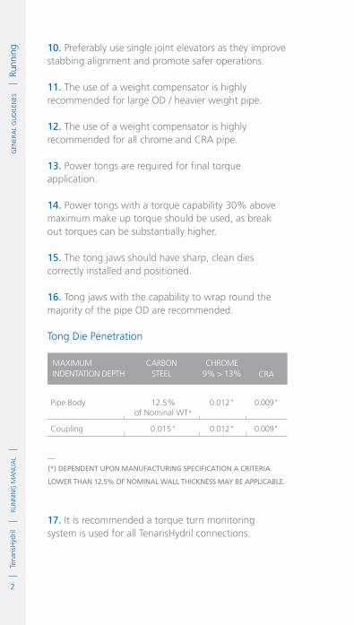
g 10. Preferably use single joint elevators as they improve stabbing alignment and promote safer operations.
11. The use of a weight compensator is highly recommended for large OD / heavier weight pipe.
12. The use of a weight compensator is highly recommended for all chrome and CRA pipe.
13. Power tongs are required for final torque application.
14. Power tongs with a torque capability 30% above maximum make up torque should be used, as break out torques can be substantially higher.
15. The tong jaws should have sharp, clean dies correctly installed and positioned.
16. Tong jaws with the capability to wrap round the majority of the pipe OD are recommended.
Tong Die Penetration
0.012"
0.012"
Pipe Body
Coupling
12.5%of Nominal WT*
0.015"
0.009"
0.009"
CHROmE 9% > 13%
CARBONSTEEl
mAxImUm INDENTATION DEPTH CRA
__
(*) DepenDent upon manufacturing specification a criteria
lower than 12.5% of nominal wall thickness may be applicable.
17. It is recommended a torque turn monitoring system is used for all TenarisHydril connections.

3
RUN
NIN
G M
AN
UA
LTe
naris
Hyd
ril
IDM
Cod
e G
DL2
3350
/1 /
Mar
ch 2
018
G
ENER
AL
GU
DIL
ENES
Runn
ingStabbing
1. Alignment is critical in ensuring a properly assembled connection without incurring damage.
2. If misalignment is evident take remedial action to minimize.
3. misalignment of more than 20% of the pipe OD outwith the corresponding box connection is deemed excessive.
ALIGNMENT
The pipe should be aligned
with the box axis.
aligneD 100% misaligneD50% misaligneD

4
RUN
NIN
G M
AN
UA
LTe
naris
Hyd
ril
GEN
ERA
L G
UD
ILEN
ES
Ru
nnin
g 4. Do not remove the pin thread protector until the joint is ready to stab in order to prevent damage from accidental mishandling.
5. Remove the pin protector and handling plug (on integral connections) while the pin is hanging in the derrick and the box is suspended in the rotary table.
6. Clean and re-inspect the connections if any doubt exists over connection integrity.
7. For Dopeless® connections ensure the rings from the protectors are not adhering to the pin or box connection.
8. Use a stabbing guide to facilitate accurate, safe stabbing of the pin into the box.
9. If an automated pipe racking system is used ensure the guide arm positions the pin end to be stabbed directly above the box connection.
10. If an automated pipe racking system is not used, ensure the pin is stabbed vertically with the assistance of someone on the stabbing board.
11. lower the joint in a smooth controlled fashion taking care to avoid damaging the connections.
12. If an error occurs when stabbing, or the pipe tilts excessively to one side, pick up, clean the connections and inspect for damage.
13. Do not roll pin into box if the pipe hangs up when stabbing.
14. A weight compensator assists in stabbing in a smooth, controlled, safe manner.

5
RUN
NIN
G M
AN
UA
LTe
naris
Hyd
ril
IDM
Cod
e G
DL2
3350
/1 /
Mar
ch 2
018
G
ENER
AL
GU
DIL
ENES
Runn
ingmake up
1. Once the pipe is stabbed commence rotation slowly to ensure the connections are not cross threaded.
2. If any indication of cross threading occurs, immediately stop assembly and counter rotate the pin to remove and inspect both connections.
3. The pipe must be stabilized during spin in.
4. maximum spin in speed should not exceed 15 RPm.
5. Final make up should be achieved in low gear below 5 RPm.
6. low gear should be engaged approximately 1 full turn prior to final make up point.
7. For chrome and CRA material the pipe should be walked in with the use of a strap wrench until hand tight, then final make up should be conducted with the power tong in low gear.
8. make up all connections with the use of an appropriately sized and correctly maintained power tong.
9. Do not latch back up tongs over box ends, this increases the risk of galling the connection.
10. Do not use pipe wrenches as back up tongs as they may damage the pipe body.
11. Do not latch tongs on any integral connection, always grip the pipe body.
12. Use full wrap-around back ups on thin walled or plastic coated pipe to reduce the possibility of damaging either pipe or coating.

6
RUN
NIN
G M
AN
UA
LTe
naris
Hyd
ril
GEN
ERA
L G
UD
ILEN
ES
Ru
nnin
g 13. monitor the rotation speed for irregularities, irregular speeds may indicate connection misalignment.
14. Joints made up at irregular speeds should be backed out and inspected for possible damage.
15. If the pipe has a tendency to wobble greatly during make up due to harmonics, wind or rig motion, reduce the make up rotation speed to prevent damage.
16. When running pipe in stands spin in speed should be reduced to prevent pipe wobble / whip.
17. If excessive wobbling persists despite reduced rotation speed, stop using the power tong for spinning in. Walk the connection in with a strap wrench. When hand tight, apply the power tong to reach optimum torque and monitor make up graph evolution.
18. Excess torque during make up or irregular rotation speed indicate poor alignment that may cause damage. Any rotational movement should be stopped until the cause is determined and corrected.
19. If handling plugs are used along with side door elevators ensure there is no contact between elevators and plug during make up as this can back the plug out of the connection.

7
RUN
NIN
G M
AN
UA
LTe
naris
Hyd
ril
IDM
Cod
e G
DL2
3350
/1 /
Mar
ch 2
018
G
ENER
AL
GU
DIL
ENES
Runn
inglowering
1. Care should be exercised when setting rotary slips to avoid shock loading the string.
2. Ensure rotary slips are set carefully to prevent crushing or gouging the pipe body.
3. Ensure the elevator slips are set well below the connection area.
integral connections:
1. Keep the handling plug in the box connection until the joint is lowered and set in the rotary slips. The plug will help keep drilling mud off the thread and seal areas if overflow occurs.
2. If fill up is required during running, the handling plug should be left installed in the box to prevent the fill up hose from damaging box threads and seals
3. Do not hammer on the box to break the handling plug free, as this may damage the connection. If necessary, hammer on the handling plug flange.

8
RUN
NIN
G M
AN
UA
LTe
naris
Hyd
ril
GEN
ERA
L G
UD
ILEN
ES
Ru
nnin
g

1
RUN
NIN
G M
AN
UA
LTe
naris
Hyd
ril
IDM
Cod
e G
DL2
3357
/1 /
Mar
ch 2
018
GEN
ERA
L G
UD
ILEN
ES
P
ullin
gPulling
BREAK OUT
1. A weight compensator should be used to avoid thread damage.
2. Use power tongs in low gear to break out connections.
3. Do not hammer on connections to assist breakout as this may cause damage.
4. During break and spinout, the pipe must be vertical and allowed to spin freely which may necessitate slacking off or unlatching elevators.
5. To break out a Blue® Series, Legacy Series or TXP® Buttress coupled connection, the back up tongs must be set on the mill side of the coupling, leaving the field side free to disengage.
For Wedge Series 500™ coupled connections, place the back up tongs on the pipe body below the coupling. This will extend connection life. Coupling turn should not occur due to the higher buck on torque applied to the mill end. If gripping the coupling of Wedge Series 500™ cannot be avoided, use a full wraparound back up tong and grip the coupling as close to the pipe end as possible. The back ups must be released as soon as the field end is disengaged, and re-set on the pipe body for spin out completion if necessary.

2
RUN
NIN
G M
AN
UA
LTe
naris
Hyd
rilG
ENER
AL
GU
DIL
ENES
Pul
ling
Tong positioning for break
out of Wedge Series 500™
coupled connections.
Tong positioning for breaking
out of Blue® Series, Legacy Series
or TenarisXP® Buttress coupled
connections.
POWER TONG
FIELDSIDE
MILLSIDE
BACK UP TONG
POWER TONG
FIELDSIDE
MILLSIDE BACK UP TONG

3
RUN
NIN
G M
AN
UA
LTe
naris
Hyd
ril
IDM
Cod
e G
DL2
3357
/1 /
Mar
ch 2
018
GEN
ERA
L G
UD
ILEN
ES
P
ullin
g6. Never grip the connection OD of any integral connection.
7. Rotation speed should not exceed 15 RPM.
8. Slow rotation speed towards the end of spin out to prevent heavy pipe ‘drop’ especially for large OD and heavy weight pipe. Count rotations until complete spin out of first joint then slow spin out speed prior to final rotation on subsequent joints.
9. Chrome and CRA connections should be walked out by hand with the use of a strap wrench.
10. Excess torque during break out or irregular rotation speed indicates poor alignment that may cause damage. Any rotational movement should be stopped until the cause is determined and corrected.
11. If excess torque is required to break out any connection check the pipe body for indications of crushing by the tong jaws.
12. Exercise care when lifting the pin out of the box. Maintaining breakout rotation and keeping the pin centered in the box when disengaging can prevent thread hang up and damage. The use of a stabbing guide will help in this process.
13. A safety clamp should be used when pulling Flush, Near Flush and Special Clearance Couplings.
14. Always use slip type elevators with special clearance and special bevel couplings.

4
RUN
NIN
G M
AN
UA
LTe
naris
Hyd
rilG
ENER
AL
GU
DIL
ENES
Pul
ling Laying Down
.Wash connections with fresh water to remove any corrosive well fluid.
.Ensure all threads and seal areas are adequately covered with thread or storage compound.
.Install a clean, undamaged thread protector on box and pin ends. The protector should be on straight and tight.
.Do not apply thread compound to Dopeless® connections.
.Dry the connections and protectors prior to fitting securely.
.Always use the correct Dopeless® protectors with the rubber rings firmly in place for Dopeless® connections.
.Ideally the bore of the pipe should be flushed clean of well fluid.
Surplus pipe
.Once running is completed, immediately clean and dry all remaining connections.
.Apply appropriate storage compound to the connections.
.Do not apply storage compound to Dopeless® connections.
.Install clean, dry thread protectors of the correct type.
.Ensure no corrosive fluids, debris or water come into contact with the connections during transportation and / or storage.

5
RUN
NIN
G M
AN
UA
LTe
naris
Hyd
ril
IDM
Cod
e G
DL2
3357
/1 /
Mar
ch 2
018
GEN
ERA
L G
UD
ILEN
ES
P
ullin
g.Dopeless® connections should be clean and dry prior to installing the correct Dopeless® protectors.
.Any pulled pipe should be treated in the same manner.
End of job / storage
.Clean any used connections to remove dope, mud and corrosive fluids using the methods indicated in the cleaning section.
.Thoroughly flush the bores of pipe to remove all contaminants and / or debris.
.Inspect cleaned connections for damage.
.Apply a corrosion-inhibiting storage compound on clean, dry connections.
.For Dopeless® connections ensure they are clean of any contaminants and dry, do not apply any compound.
.Install clean, dry, undamaged thread protectors, ensure the correct protectors are used for Dopeless® connections with the rubber rings in place.
.For long term storage of Dopeless® connections, refurbishment by qualified personnel is recommended.
.Damaged and rejected connections should also be protected in order to prevent the connection sustaining irreparable damage and possibly rendering the whole joint as scrap.

6
RUN
NIN
G M
AN
UA
LTe
naris
Hyd
rilG
ENER
AL
GU
DIL
ENES
Pul
ling .Rejected connections must be properly marked.
.All pipe returned from the rig should be fully cleaned and inspected as soon as possible.
.Dopeless® pipe returned from the rig should be inspected and refurbished by a Tenaris representative as soon as possible.

1
RUN
NIN
G M
AN
UA
LTe
naris
Hyd
ril
GEN
ERA
L G
UD
ILEN
ES
H
andl
ing
/ Lift
Plu
gs
IDM
Cod
e G
DL2
3351
/1 /
Mar
ch 2
018
Handling / Lift Plugs
1. Handling plugs are essential in order to run flush and near flush type connections.
2. Handling Plugs and Lifting Plugs are tubular accessories used on flush and semi flush integral connections. They are a pin threaded steel plug provided with holes in the upper flange. The upper flange being of such a design as to allow the face of a side door elevator to abut the flange with enough overlap to allow the pipe or string to be lifted. The thread finish of the plugs is generally phosphate.
3. Although the physical appearance of both types of plug are similar, they are designed for different purposes:
Handling Plugs
1. Are designed to withstand the weight of a single pipe or a stand of up to 3 pipe maximum.
2. Are used for handling the pipe and protecting the box end connection as the pipe is brought through the V-door and into the derrick.
3. The maximum load capacity should be stamped on the top of the flange. If no maximum load capacity is indicated the device should be used to lift no more than 1 joint.

2
RUN
NIN
G M
AN
UA
LTe
naris
Hyd
ril
GEN
ERA
L G
UD
ILEN
ES
H
andl
ing
/ Lift
Plu
gs
lifting Plugs
1. Are designed to withstand the weight of the whole tubular string.
2. The maximum load capacity must be stamped on the flange. If no rating is stamped or is illegible, it should be used to lift no more than 1 joint.
3. The maximum lift capacity stamped on the plug should never be exceeded.
load Rated Handling Plugs
1. These are a ‘hybrid’ design which although not rated to the same lift capacity as the connection can lift a load far in excess of a handling plug.
2. Tenaris generally manufacture load rated handling plugs.
3. Any genuine Tenaris designed and manufactured handling / lift plug will have a unique part number and maximum load rating hard stamped on the flange. If no load rating is indicated these should be used to lift no more than 1 joint.
4. The load rating stamped on any Tenaris plug should never be exceeded.

3
RUN
NIN
G M
AN
UA
LTe
naris
Hyd
ril
IDM
Cod
e G
DL2
3351
/1 /
Mar
ch 2
018
G
ENER
AL
GU
DIL
ENES
Han
dlin
g / L
ift P
lugs
5. Plugs are designed with a low interference thread and with no metal seals. This allows them to be installed in the box end by hand and tightened with the aid of a steel bar inserted through the flange holes.
6. Maximum load stamped upon genuine Tenaris handling plugs has been load rated as per API Specification 8A.
Handling Plug
The complete removal of all storage
compounds is imperative.
OD"
ID"

4
RUN
NIN
G M
AN
UA
LTe
naris
Hyd
ril
GEN
ERA
L G
UD
ILEN
ES
H
andl
ing
/ Lift
Plu
gs
7. Prior to running, check the condition and fit of the plugs, ensure 3 or 4 are available. If a plug does not make up correctly to a connection check the plug and connection for thread damage, debris on the threads, mashed box or box ovality.
8. Special attention should be paid to connections that are not interchangeable for the same OD and different weight, for example Blue® Near Flush. For these cases the handling and lifting plugs are not interchangeable. Also be aware that some connections have a limited same size different weight interchange capability which will also apply to the interchange capability of the plugs.
9. Interchange capability can be verified in the TenarisHydril premium connections catalogue.
10. Visual inspection of plug threads and box end is mandatory before each make up.
11. Ensure the handling / lift plug threads are completely clean and free of all contamination.
12. In the particular case of Wedge connections in chrome or CRA grades, it is recommended that handling / lifting plugs and all accessories (cement head, circulating swage etc) are peened and moly-coated prior to use.
13. Make up the plug by hand and then snug up tight with the assistance of a bar inserted into the holes of the flange.
14. It is not necessary to apply thread compound to TenarisHydril manufactured handling plugs, especially if running Dopeless® connections.

5
RUN
NIN
G M
AN
UA
LTe
naris
Hyd
ril
IDM
Cod
e G
DL2
3351
/1 /
Mar
ch 2
018
G
ENER
AL
GU
DIL
ENES
Han
dlin
g / L
ift P
lugs
Blue® near FlusH, slX®, MaCii™
Wedge series 500™ Plug
.Wedge thread plugs will make up to the end of the thread. If more than 50% of a thread is showing remove plug, clean or repair if required.
.Near Flush, SLX® and MACII™ plugs will make up to box / standoff face.
15. Check for correct final make up position:

6
RUN
NIN
G M
AN
UA
LTe
naris
Hyd
ril
GEN
ERA
L G
UD
ILEN
ES
H
andl
ing
/ Lift
Plu
gs
Handling and CaRe of Plugs
1. Correct handling practices and sound judgment must be used at all times to maintain the rated Lift capacity of any plug.
2. Damaged plugs should be inspected by a qualified Tenaris Field Service Specialist prior to further use.
3. The ID of the plugs must not be bored out as this will reduce the rated lift capacity of the plugs.
4. The OD of the plugs must not be turned down as this will also reduce the rated lift capacity of the plugs.
5. During lifting operations, if the plug is subjected to heavy impact loading, use of the plug should be suspended until an inspection is performed.
6. Particular care must be taken when using handling plugs and side door elevators. Ensure the elevators are not in contact with the plug whilst the pipe is being made up as this will back the plug out of the connection.
7. Many people treat handling / lift plugs as they would protectors, this is bad practice.
8. When rotating the plugs from drill floor to pipe area care should be taken to ensure the plugs are not damaged, these are machined parts and as such should be treated like any pipe connection.
9. Additionally, care should be taken in preventing the plugs from becoming contaminated with grit or debris, if this occurs the plugs must be thoroughly cleaned prior to being made up to a connection.

7
RUN
NIN
G M
AN
UA
LTe
naris
Hyd
ril
IDM
Cod
e G
DL2
3351
/1 /
Mar
ch 2
018
G
ENER
AL
GU
DIL
ENES
Han
dlin
g / L
ift P
lugs
10. Tenaris will neither endorse nor guarantee any handling or lift plug designed and manufactured by any other company. Although these accessories may have a genuine TenarisHydril connection machined upon them the design and lift capabilities of the item are unknown to Tenaris therefore these items are used at the user’s own discretion. Any query regarding the lifting capability of such items should be directed to the original manufacturer.

8
RUN
NIN
G M
AN
UA
LTe
naris
Hyd
ril
GEN
ERA
L G
UD
ILEN
ES
H
andl
ing
/ Lift
Plu
gs

Technical Recommendations


1
RUN
NIN
G M
AN
UA
LTe
naris
Hyd
ril
IDM
Cod
e G
DL2
3352
/1 /
Mar
ch 2
018
TeC
HN
ICA
L Re
Co
MM
eND
ATI
oN
s
To
rque
App
licat
ionTorque Application
1. The correct application of torque for the connection type, OD, weight and grade being assembled is imperative in ensuring the connection can perform optimally.
2. The power tong snub line should be attached to a back up post, leveled and positioned at a 90° angle to the power tongs.
3. The snub line should be of cored wire construction, nylon slings or chains are not acceptable.
1
power tong torque
90°

2
RUN
NIN
G M
AN
UA
LTe
naris
Hyd
rilTe
cH
NIc
AL
Rec
oM
MeN
dA
TIo
Ns
To
rque
App
licat
ion
4. Ideally jaws which allow wrap around die contact of the pipe body should be used.
5. Tongs should be placed on the pipe body either side of the connection.
6. Do not grip the coupling or OD of integral connections.
Make up
1. Power tong, upper view.
2. Load cell installation, side view.
load cell close as practical
90°
short as practical
2

3
RUN
NIN
G M
AN
UA
LTe
naris
Hyd
ril
IDM
Cod
e G
DL2
3352
/1 /
Mar
ch 2
018
TeC
HN
ICA
L Re
Co
MM
eND
ATI
oN
s
To
rque
App
licat
ion
Make up
Power tong positioning for make up
of coupled connections.
3
power tong
power tong
Fieldside
Millside
BacK up tong
BacK up tong
4
4
RUN
NIN
G M
AN
UA
LTe
naris
Hyd
rilTe
cH
NIc
AL
Rec
oM
MeN
dA
TIo
Ns
To
rque
App
licat
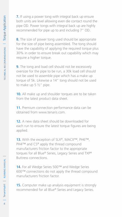
ion 7. If using a power tong with integral back up ensure
both units are level allowing even die contact round the pipe OD. Power tongs with integral back up are highly recommended for pipe up to and including 7" OD.
8. The size of power tong used should be appropriate for the size of pipe being assembled. The tong should have the capability of applying the required torque plus 30% in order to ensure break out capability which may require a higher torque.
9. The tong and load cell should not be excessively oversize for the pipe to be run, a 30k load cell should not be used to assemble pipe which has a make up torque of 5k. Likewise a 14" tong should not be used to make up 5 ½" pipe.
10. All make up and shoulder torques are to be taken from the latest product data sheet.
11. Premium connection performance data can be obtained from www.tenaris.com.
12. A new data sheet should be downloaded for each run to ensure the latest torque figures are being applied.
13. With the exception of SLX®, MACII™, PH6™, PH4™ and CS® apply the thread compound manufacturers friction factor to the appropriate torques for all Blue® Series, Legacy Series and TXP® Buttress connections.
14. For all Wedge Series 500™ and Wedge Series 600™ connections do not apply the thread compound manufacturers friction factor.
15. Computer make up analysis equipment is strongly recommended for all Blue® Series and Legacy Series.

5
RUN
NIN
G M
AN
UA
LTe
naris
Hyd
ril
IDM
Cod
e G
DL2
3352
/1 /
Mar
ch 2
018
TeC
HN
ICA
L Re
Co
MM
eND
ATI
oN
s
To
rque
App
licat
ion16. Computer make up analysis equipment is strongly
recommended for all Wedge Series 500™ and Wedge Series 600™ connections in chrome and CRA.
17. Computer make up analysis equipment is recommended for all Wedge Series 500™ and Wedge Series 600™ connections.
18. Computer equipment should have the capability to display torque turn analysis.
19. Torque Time analysis is not accurate enough for premium connections.
20. Computer equipment capable of 500 pulses per turn but preferably 1000ppt is required.
21. All measuring equipment such as load cells must be calibrated.
22. Dump valve actuation should be set at optimum torque.
23. Check dump valve actuation on the pipe body prior to assembling the first connection.
24. Some TenarisHydril connections have visual make up indicators. These indicators are an aid to be used in conjunction with good make up practices and computer graph interpretation. See connection specific running guidelines.
25. The following data should be loaded into the computer:.Reference torque .Minimum shoulder torque.Maximum shoulder torque .Minimum make up torque .Optimum make up torque.Maximum make up torque

6
RUN
NIN
G M
AN
UA
LTe
naris
Hyd
rilTe
cH
NIc
AL
Rec
oM
MeN
dA
TIo
Ns
To
rque
App
licat
ion .Calibration value of the load cell.Dump valve sensitivity.Turn transducer sensitivity
26. Initially it is recommended to set reference torque at 5% of optimum. Thereafter it can be adjusted to allow at least the last full turn of assembly to be displayed.
27. Special clearance or matched strength connections may require torque adjustment, contact the local Tenaris Technical Sales Representative or: [email protected].
ReFeRenCe TORqueThe torque set in the computer where graph depiction begins.
MInIMuM SHOuLDeR TORqueThe lowest point at which indicated shoulder can be accepted.
MAXIMuM SHOuLDeR TORqueThe highest point at which indicated shoulder can be accepted.
MInIMuM MAke uP TORque The lowest acceptable make up torque.
OPTIMuM MAke uP TORqueThe ideal applied make up torque.
MAXIMuM MAke uP TORqueThe highest acceptable make up torque.
OPeRATIOnAL TORqueMaximum useable torque measured at surface when rotating the string. Operational torque should never be exceeded.*
YIeLD TORqueThe torque at which deformation of the connection is expected. Yield torque should never be approached.
TORque DeFInITIOnS
__
(*) prior to applying operational torque contact tenaris For
analysis oF rpM, rotation tiMe and Fatigue.

7
RUN
NIN
G M
AN
UA
LTe
naris
Hyd
ril
IDM
Cod
e G
DL2
3352
/1 /
Mar
ch 2
018
TeC
HN
ICA
L Re
Co
MM
eND
ATI
oN
s
To
rque
App
licat
ion
XBlue® Series, Legacy Series, TXP® Buttress
Wedge Series 500™
and Wedge Series 600™ X
COnneCTIOn LOWeR TORque HIgHeR TORque
Combining Different Weight / grade
1. When combining different weight / grade of connections ensure compatibility of weight as indicated in the TenarisHydril premium connections catalogue. If any doubt exists as to interchange capability contact the local Tenaris Technical Sales representative.
2. For all Blue® Series, Legacy Series and TXP® Buttress connections use the lower of the two torque values.
3. For Wedge Series 500™ and Series 600™ connections, including interchangeable designs, use the higher of the two torque values.
4. When assembling Blue® Series, Legacy Series or TXP® Buttress accessories with a large disparity in OD / ID, higher shoulder points may be encountered. Contact a Tenaris representative to validate if a change in torque is required.
5. If connections with a grade disparity larger than 30kSI are to be mixed contact Tenaris to validate torques.
__
note: iF diFFerent weight oF connections are coMBined there
will Be a step in the Bore.

8
RUN
NIN
G M
AN
UA
LTe
naris
Hyd
rilTe
cH
NIc
AL
Rec
oM
MeN
dA
TIo
Ns
To
rque
App
licat
ion
Torque Application Wedge Series 500™ and Wedge Series 600™
1. For doped variant Wedge Series 500™ and Wedge Series 600™ connections, use the following process on the first joint (double bump):
2. Make up the first joint to the specified optimum torque and relax the tongs.
ASSeMBLeD COnneCTIOnS
OF DIFFeRenT WeIgHT
1. Lighter pin into heavier box.
2. Heavier pin into lighter box.
BoX
pin
BoX
pin
1.
2.

9
RUN
NIN
G M
AN
UA
LTe
naris
Hyd
ril
IDM
Cod
e G
DL2
3352
/1 /
Mar
ch 2
018
TeC
HN
ICA
L Re
Co
MM
eND
ATI
oN
s
To
rque
App
licat
ion
3. Draw a longitudinal line across the pin and box and re-apply the optimum torque as indicated in the Data Sheet.
4. If the drawn line does not move more than ½" after the second torque application, continue running the rest of the string normally using the specified optimum torque.
5. If the drawn line moves more than ½" after the second torque application, a portion of the torque is being absorbed by other variables during assembly. If this occurs, do the following:
6. Increase the optimum torque by 20% and re-apply the torque.
7. Draw a second line and re-apply optimum torque plus 20%.
8. If the second drawn line does not move more than ½", continue running the remainder of the string using the 20% higher optimum torque.
9. If the second drawn line moves more than ½", recheck the alignment, dope application and tong function, then repeat this procedure until the drawn line moves less than ½".
10. It is best practice to repeat this procedure if the tongs are changed out during the run.
11. Sufficient torque must be applied to ensure it is not lost to other variables in the make up system such as rig motion, misalignment or tong inconsistencies.
12. For doped variant Wedge Series 500™ and Wedge Series 600™ connections in sizes 10 3/4" and larger either: .Apply the optimum torque twice on every connection..Hold the torque for several seconds on every connection.

10
RUN
NIN
G M
AN
UA
LTe
naris
Hyd
rilTe
cH
NIc
AL
Rec
oM
MeN
dA
TIo
Ns
To
rque
App
licat
ion
13. For all Wedge Series 500™ and Wedge Series 600™ Dopeless® connections apply optimum torque only once without holding.
14. Always check the visual make up verification aid if available, refer to specific product running guidelines.
15. During freezing weather, maximum make up torque may be required to overcome running compound viscosity and ensure correct make up.
16. When using tubing as a work string or test string, good practice is to make up the first one or two turns by hand to extend the life of the connection.

IDM
Cod
e G
DL2
3353
/1 /
Mar
ch 2
018
1
RUN
NIN
G M
AN
UA
LTe
naris
Hyd
rilTe
cH
NIc
AL
Rec
oM
MeN
dA
TIo
Ns
Bl
ue® s
erie
s an
d Le
gacy
ser
ies
Mak
e up
Acc
epta
nce Blue® Series and
Legacy Series Make up Acceptance
1. Computer graph interpretation is exactly as described, ‘interpretation’ which means it is not an exact science. Many things must be taken into account before accepting a graph; condition of pipe, weather, alignment, thread compound, pipe or rig movement, temperature and most importantly the behaviour exhibited by the graphs of the connections previously made up during the run. There are however some basic rules and tenets which if understood along with specific connection mechanics, allow the area of interpretation to remain within anticipated parameters. The following examples are indicative and are only for guidance as to the acceptance of any given connection assembly. Many variables can produce graphs which differ to the ones depicted, which with the correct understanding and knowledge can still be acceptable make up profiles.
2. The accuracy of any make up graph is only as good as the accuracy of the equipment used and the data input. Therefore it is imperative all equipment used is well maintained and calibrated. Data input should be cross checked to ensure accuracy and saved.
3. A computer graph for a shouldered connection can essentially be broken down into four component parts:.Thread and seal interference build slope..Distinct, identifiable shoulder point within set shoulder parameters..Linear delta torque build to within set torque parameters after shoulder..Delta turns.

2
RUN
NIN
G M
AN
UA
LTe
naris
Hyd
rilTe
cH
NIc
AL
Rec
oM
MeN
dA
TIo
Ns
Bl
ue® s
erie
s an
d Le
gacy
ser
ies
Mak
e up
Acc
epta
nce 4. Individually and collectively the above four
components must be analyzed within known characteristics for the given connection design in order for the make up graph to be interpreted accurately.
TOR
QU
E
TURNS
MAX. SHOULDER POINT
MIN. SHOULDER POINT
Shoulder Point
Thread & Seal Interference
Delta Torque
Delta TurnsMAXIMUM TORQUE
MINIMUM TORQUE
OPTIMUM TORQUE
Typical graph profile
5. The four basic component parts of a graph should exhibit the following characteristics:
.Smooth, continuous thread and seal interference build exhibiting no unusual discontinuities..A distinct, identifiable shoulder point within set shoulder parameters..An exponential delta torque build after shoulder point exhibiting no discontinuities. .Delta turns.
6. Encountering high torque at the commencement of rotation or soon after can indicate cross threading of the connections. Immediately stop rotation, back out and inspect the connections for damage.

3
RUN
NIN
G M
AN
UA
LTe
naris
Hyd
ril
IDM
Cod
e G
DL2
3353
/1 /
Mar
ch 2
018
TeC
HN
ICA
L Re
Co
MM
eND
ATI
oN
s
Bl
ue® s
erie
s an
d Le
gacy
ser
ies
Mak
e up
Acc
epta
nce 7. Occasionally some connections can exhibit a change
in angle during seal engagement this is perfectly acceptable. This profile may be evident on every make up of a particular string or may occur sporadically throughout the run.
TOR
QU
E
TURNS
MAX. SHOULDER POINT
MIN. SHOULDER POINT
Shoulder Point
Thread Interference
OPTIMUM TORQUE
SealInterference
8. Although a shouldered connection will exhibit the four component parts described previously the configuration of each make up can vary considerably. Many factors influence the profile of a computer graph; weather, rig movement, pipe sway, travelling block alignment or sway, pipe bend, tong slip, rotation speed, snub line whip, elevator or other equipment contact on the pipe, material grade, temperature, accuracy of the make up equipment, dope type, dope temperature, dope consistency, dope application, dope contamination, dope friction factor and quantity of dope applied. Any and all of which can be a contributing factor to graph profile outcome.

4
RUN
NIN
G M
AN
UA
LTe
naris
Hyd
rilTe
cH
NIc
AL
Rec
oM
MeN
dA
TIo
Ns
Bl
ue® s
erie
s an
d Le
gacy
ser
ies
Mak
e up
Acc
epta
nce 9. It is imperative data is accurately input to the
computer and stored correctly. Shoulder points must be accurately pinpointed whether automatically or manually.
10. There are many reasons for not accepting a make up graph and therefore breaking out the connection, priority among these is doubt with the integrity of the assembly leading to the connections leaking down hole. Unacceptable graphs require the connections to be fully disassembled with both pin and box connections cleaned and inspected for damage. Only when this process has been completed and no damage found, can the connections then be re-assembled. Partial break out is inadvisable. All graphs should be kept for post job analysis including unacceptable make up graphs.
11 The following series of graphs, which are by no means exhaustive, are indicative of the many different profiles witnessed, both acceptable and unacceptable. In certain circumstances an anomalous graph profile can be accepted after investigation by a qualified Tenaris Field Service Specialist but only within the context of the particular run of pipe it is encountered. This would only be the case if the cause has been identified and is deemed by the specialist as non-detrimental to connection integrity. If no remedy can be effected further graphs of a similar type can be accepted during that particular run.
12. These graphs are applicable to Blue® Series and Legacy Series shouldered connections. The only difference being, SLX®, MACII™, PH6™, PH4™ and CS® shouldered connections have no defined shoulder point criteria other than an identifiable shoulder point must be in evidence.

5
RUN
NIN
G M
AN
UA
LTe
naris
Hyd
ril
IDM
Cod
e G
DL2
3353
/1 /
Mar
ch 2
018
TeC
HN
ICA
L Re
Co
MM
eND
ATI
oN
s
Bl
ue® s
erie
s an
d Le
gacy
ser
ies
Mak
e up
Acc
epta
nce Computer Graph Blue® SerieS
and leGaCy SerieS
For Blue® Series and Legacy Series connections there is a maximum allowable delta turn criteria which should be applied.
TOR
QU
E
TURNS
MAX. SHOULDER POINT
≤ 0.12
MIN. SHOULDER POINT
OPTIMUM TORQUE
Delta Torque
Max Delta Turns ≤ 0.12
accepTable
The criteria for maximum
allowable delta turn of
Blue® Series or Legacy Series
connections, including
Dopeless® technology,
in sizes 5 1/2" and below is
as follows:.A final torque above minimum
and below maximum must be
attained..The maximum delta turn can
be no more than 0.12 of a turn.
.Loss of linearity is allowed
within the acceptable
maximum delta turn. .For any delta above 0.12 of a
turn reject both connections.
Above 5 1/2" both for
Blue® Series or Legacy Series
connections the maximum
delta criteria is 0.1.

6
RUN
NIN
G M
AN
UA
LTe
naris
Hyd
rilTe
cH
NIc
AL
Rec
oM
MeN
dA
TIo
Ns
Bl
ue® s
erie
s an
d Le
gacy
ser
ies
Mak
e up
Acc
epta
nce Computer Graph Blue® SerieS
and leGaCy SerieSTO
RQ
UE
TURNS
MAX. SHOULDER POINT
Max.0.12
MIN. SHOULDER POINT
OPTIMUM TORQUE
accepTable
For pipe sizes 5 1/2" and
below, if a graph with a
larger than normal delta turn
is displayed, with or without
loss of linearity, the process to
follow is:.A final torque above minimum
and below maximum must be
attained.
.Expand the graph and ensure
the shoulder point is accurately
indicated, adjust if necessary..If the delta turn is > 0.12 reject
both connections. .If the delta turn is ≤ 0.12
accept the make up.

7
RUN
NIN
G M
AN
UA
LTe
naris
Hyd
ril
IDM
Cod
e G
DL2
3353
/1 /
Mar
ch 2
018
TeC
HN
ICA
L Re
Co
MM
eND
ATI
oN
s
Bl
ue® s
erie
s an
d Le
gacy
ser
ies
Mak
e up
Acc
epta
nce Computer Graph Blue® SerieS
and leGaCy SerieS
TOR
QU
E
TURNS
MAX. SHOULDER POINT
MIN. SHOULDER POINT
Shoulder Point
OPTIMUM TORQUE
accepTable
Thread and seal build profile
with smooth hump effect not
exceeding shoulder point.
Possible Causes.Excessive running compound.High friction factor running
compound.Slight misalignment.Pipe sway.Rig movement.Pipe bend.Contact on pipe by other
equipment
Recommendations
If no obvious reason is evident
break out the first make up
and inspect both connections
for damage, if no damage
found continue to accept
similar graph profiles.

8
RUN
NIN
G M
AN
UA
LTe
naris
Hyd
rilTe
cH
NIc
AL
Rec
oM
MeN
dA
TIo
Ns
Bl
ue® s
erie
s an
d Le
gacy
ser
ies
Mak
e up
Acc
epta
nce Computer Graph Blue® SerieS
and leGaCy SerieSTO
RQ
UE
TURNS
MAX. SHOULDER POINT
MIN. SHOULDER POINT
OPTIMUM TORQUE
accepTable
Curved thread and seal
interference build with smooth
profile.
Possible Causes.Excess thread compound.High friction factor thread
compound.Low temperature thread
compound.Pipe sway.Rig movement.Pipe bend.Contact on pipe by other
equipment
If compound is thought to
be the cause ensure it is fully
stirred and warm if possible.
Eradicate any contact by other
equipment during make up.
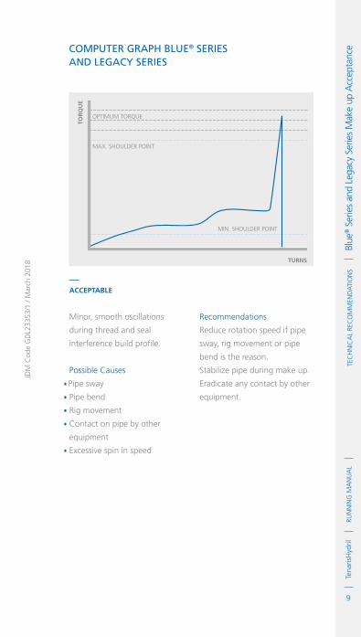
9
RUN
NIN
G M
AN
UA
LTe
naris
Hyd
ril
IDM
Cod
e G
DL2
3353
/1 /
Mar
ch 2
018
TeC
HN
ICA
L Re
Co
MM
eND
ATI
oN
s
Bl
ue® s
erie
s an
d Le
gacy
ser
ies
Mak
e up
Acc
epta
nce Computer Graph Blue® SerieS
and leGaCy SerieS
TOR
QU
E
TURNS
MAX. SHOULDER POINT
MIN. SHOULDER POINT
OPTIMUM TORQUE
accepTable
Minor, smooth oscillations
during thread and seal
interference build profile.
Possible Causes.Pipe sway. Pipe bend. Rig movement. Contact on pipe by other
equipment. Excessive spin in speed
Recommendations
Reduce rotation speed if pipe
sway, rig movement or pipe
bend is the reason.
Stabilize pipe during make up.
Eradicate any contact by other
equipment.

10
RUN
NIN
G M
AN
UA
LTe
naris
Hyd
rilTe
cH
NIc
AL
Rec
oM
MeN
dA
TIo
Ns
Bl
ue® s
erie
s an
d Le
gacy
ser
ies
Mak
e up
Acc
epta
nce Computer Graph Blue® SerieS
and leGaCy SerieSTO
RQ
UE
TURNS
MAX. SHOULDER POINT
MIN. SHOULDER POINT
OPTIMUM TORQUE
accepTable
Single tong slip during thread
and seal build.
Possible Causes .Clogged tong dies.Worn tong dies.Incorrect dies or tong jaws.Tong not level.Snub line movement.Wet or oil covered pipe OD
Recommendations
Accept if the tong slip is
momentary and the torque build
returns to previous build slope.
Take action to prevent
reoccurrence.Clean or replace tong dies..Ensure tong and back up is
level and dies contact pipe OD
evenly.
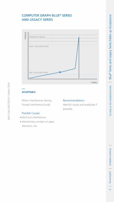
11
RUN
NIN
G M
AN
UA
LTe
naris
Hyd
ril
IDM
Cod
e G
DL2
3353
/1 /
Mar
ch 2
018
TeC
HN
ICA
L Re
Co
MM
eND
ATI
oN
s
Bl
ue® s
erie
s an
d Le
gacy
ser
ies
Mak
e up
Acc
epta
nce Computer Graph Blue® SerieS
and leGaCy SerieS
TOR
QU
E
TURNS
MAX. SHOULDER POINT
MIN. SHOULDER POINT
OPTIMUM TORQUE
accepTable
Minor interference during
thread interference build.
Possible Causes.Electrical interference. Momentary contact on pipe,
elevators, etc.
Recommendations
Identify cause and eradicate if
possible.

12
RUN
NIN
G M
AN
UA
LTe
naris
Hyd
rilTe
cH
NIc
AL
Rec
oM
MeN
dA
TIo
Ns
Bl
ue® s
erie
s an
d Le
gacy
ser
ies
Mak
e up
Acc
epta
nce Computer Graph Blue® SerieS
and leGaCy SerieSTO
RQ
UE
TURNS
MAX. SHOULDER POINT
MIN. SHOULDER POINT
Low Shoulder Point
OPTIMUM TORQUE
UnaccepTable
Low shoulder point.
Possible Causes .Incorrect torque applied.Incorrect thread compound
friction factor.Contaminated thread
compound.Substance contamination of
connections.Storage compound not cleaned
off prior to application of
thread compound.Other friction reducer.Incorrect load cell / data
reading.Low thread interference
Recommendations.Break out, clean and inspect
both connections for damage..Ensure connections are cleaned
using methods recommended
in cleaning section of this
document..Ensure connections are dry if
possible..If no damage found
decrease amount of thread
compound applied, respecting
recommended distribution
then re-make up connection.
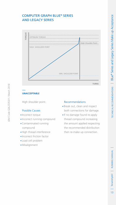
13
RUN
NIN
G M
AN
UA
LTe
naris
Hyd
ril
IDM
Cod
e G
DL2
3353
/1 /
Mar
ch 2
018
TeC
HN
ICA
L Re
Co
MM
eND
ATI
oN
s
Bl
ue® s
erie
s an
d Le
gacy
ser
ies
Mak
e up
Acc
epta
nce Computer Graph Blue® SerieS
and leGaCy SerieS
TOR
QU
E
TURNS
MAX. SHOULDER POINT
High Shoulder Point
MIN. SHOULDER POINT
OPTIMUM TORQUE
UnaccepTable
High shoulder point.
Possible Causes.Incorrect torque .Incorrect running compound.Contaminated running
compound.High thread interference.Incorrect friction factor.Load cell problem.Misalignment
Recommendations.Break out, clean and inspect
both connections for damage..If no damage found re-apply
thread compound increasing
the amount applied respecting
the recommended distribution
then re-make up connection.

14
RUN
NIN
G M
AN
UA
LTe
naris
Hyd
rilTe
cH
NIc
AL
Rec
oM
MeN
dA
TIo
Ns
Bl
ue® s
erie
s an
d Le
gacy
ser
ies
Mak
e up
Acc
epta
nce Computer Graph Blue® SerieS
and leGaCy SerieSTO
RQ
UE
TURNS
MAX. SHOULDER POINT
MIN. SHOULDER POINT
OPTIMUM TORQUE
UnaccepTable
Low final torque.
Possible Causes .Incorrect torque input.Incorrect dump valve function.Load cell error.Operator error
Recommendations.Break out clean and inspect
both connections for damage..If no damage found re-apply
thread compound then
re-make up connection.

15
RUN
NIN
G M
AN
UA
LTe
naris
Hyd
ril
IDM
Cod
e G
DL2
3353
/1 /
Mar
ch 2
018
TeC
HN
ICA
L Re
Co
MM
eND
ATI
oN
s
Bl
ue® s
erie
s an
d Le
gacy
ser
ies
Mak
e up
Acc
epta
nce Computer Graph Blue® SerieS
and leGaCy SerieS
TOR
QU
E
TURNS
MAX. SHOULDER POINT
MIN. SHOULDER POINT
OPTIMUM TORQUE
UnaccepTable
High final torque.
Possible Causes.Incorrect torque .Incorrect dump valve function.Load cell error.Operator error.High momentum
Recommendations.Break out clean and inspect
both connections for damage..If no damage found re-apply
thread compound then
re-make up connection.

16
RUN
NIN
G M
AN
UA
LTe
naris
Hyd
rilTe
cH
NIc
AL
Rec
oM
MeN
dA
TIo
Ns
Bl
ue® s
erie
s an
d Le
gacy
ser
ies
Mak
e up
Acc
epta
nce Computer Graph Blue® SerieS
and leGaCy SerieSTO
RQ
UE
TURNS
MAX. SHOULDER POINT
MIN. SHOULDER POINT
OPTIMUM TORQUE
UnaccepTable
Short / incomplete graph.
Possible Causes .Reference torque set too high .Late gear change.High initial interference
Recommendations.Break out clean and inspect
both connections for damage..If no damage found re-apply
thread compound then
re-make up connection. .Lower reference torque..Stabilize pipe during stabbing
and make up.

17
RUN
NIN
G M
AN
UA
LTe
naris
Hyd
ril
IDM
Cod
e G
DL2
3353
/1 /
Mar
ch 2
018
TeC
HN
ICA
L Re
Co
MM
eND
ATI
oN
s
Bl
ue® s
erie
s an
d Le
gacy
ser
ies
Mak
e up
Acc
epta
nce Computer Graph Blue® SerieS
and leGaCy SerieS
TOR
QU
E
TURNS
MAX. SHOULDER POINT
MIN. SHOULDER POINT
OPTIMUM TORQUE
UnaccepTable
Over torque with yield.
Possible Causes.Incorrect torque .Incorrect thread compound.Contaminated thread
compound.Storage compound not cleaned
off correctly.Incorrect friction factor.Disparity of connection grade
/ weight.Load cell error.Equipment malfunction.Incorrect tong arm length .Operator error
Recommendations
Reject both pin and box
connections.

18
RUN
NIN
G M
AN
UA
LTe
naris
Hyd
rilTe
cH
NIc
AL
Rec
oM
MeN
dA
TIo
Ns
Bl
ue® s
erie
s an
d Le
gacy
ser
ies
Mak
e up
Acc
epta
nce Computer Graph Blue® SerieS
and leGaCy SerieSTO
RQ
UE
TURNS
MAX. SHOULDER POINT
MIN. SHOULDER POINT
OPTIMUM TORQUE
UnaccepTable
Yielded connection.
Possible Causes .Incorrect torque .Incorrect thread compound.Contaminated thread
compound.Storage compound not cleaned
off correctly.Incorrect friction factor.Disparity of connection grade
/ weight.Load cell error.Equipment malfunction.Incorrect tong arm length .Operator error
Recommendations
Reject both pin and box
connections.
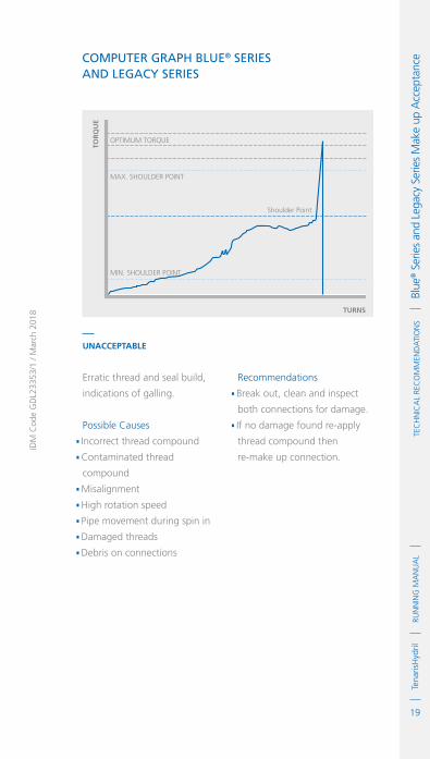
19
RUN
NIN
G M
AN
UA
LTe
naris
Hyd
ril
IDM
Cod
e G
DL2
3353
/1 /
Mar
ch 2
018
TeC
HN
ICA
L Re
Co
MM
eND
ATI
oN
s
Bl
ue® s
erie
s an
d Le
gacy
ser
ies
Mak
e up
Acc
epta
nce Computer Graph Blue® SerieS
and leGaCy SerieS
TOR
QU
E
TURNS
MAX. SHOULDER POINT
MIN. SHOULDER POINT
Shoulder Point
OPTIMUM TORQUE
UnaccepTable
Erratic thread and seal build,
indications of galling.
Possible Causes.Incorrect thread compound.Contaminated thread
compound.Misalignment.High rotation speed.Pipe movement during spin in.Damaged threads .Debris on connections
Recommendations.Break out, clean and inspect
both connections for damage..If no damage found re-apply
thread compound then
re-make up connection.

20
RUN
NIN
G M
AN
UA
LTe
naris
Hyd
rilTe
cH
NIc
AL
Rec
oM
MeN
dA
TIo
Ns
Bl
ue® s
erie
s an
d Le
gacy
ser
ies
Mak
e up
Acc
epta
nce Computer Graph Blue® SerieS
and leGaCy SerieSTO
RQ
UE
TURNS
MAX. SHOULDER POINT
MIN. SHOULDER POINT
Shoulder Point
OPTIMUM TORQUE
UnaccepTable
Hump effect exceeding final
shoulder.
Possible Causes .Excessive thread compound
application.Contaminated thread
compound.Debris on connections.High friction factor thread
compound.Pipe movement during spin in.External contact on pipe from
other equipment.Misalignment
Recommendations.Break out connections
exhibiting this profile, clean
and inspect both connections
for damage..If no damage found re-apply
thread compound, reducing
quantity then re-make up
connection. .Eradicate any other external
influence causing this effect.

21
RUN
NIN
G M
AN
UA
LTe
naris
Hyd
ril
IDM
Cod
e G
DL2
3353
/1 /
Mar
ch 2
018
TeC
HN
ICA
L Re
Co
MM
eND
ATI
oN
s
Bl
ue® s
erie
s an
d Le
gacy
ser
ies
Mak
e up
Acc
epta
nce Computer Graph Blue® SerieS
and leGaCy SerieS
TOR
QU
E
TURNS
MAX. SHOULDER POINT
MIN. SHOULDER POINT
OPTIMUM TORQUE
UnaccepTable
Non defined shoulder point.
Possible Causes.Incorrect torque .Misalignment.Pipe movement during spin in.Debris on threads.High friction factor thread
compound.Excessive thread compound
application.Slow final rotation speed.False shoulder encountered
Recommendations.Break out, clean and inspect
both connections for damage..If no damage found re-apply
thread compound then
re-make up connection.

22
RUN
NIN
G M
AN
UA
LTe
naris
Hyd
rilTe
cH
NIc
AL
Rec
oM
MeN
dA
TIo
Ns
Bl
ue® s
erie
s an
d Le
gacy
ser
ies
Mak
e up
Acc
epta
nce Computer Graph Blue® SerieS
and leGaCy SerieSTO
RQ
UE
TURNS
MAX. SHOULDER POINT
MIN. SHOULDER POINT
OPTIMUM TORQUE
UnaccepTable
Sharp spike or interference
prior to shoulder point.
Possible Causes .Galling of threads or seal.Contaminated thread
compound.Debris on threads / seals.Sudden pipe movement prior
to shoulder.Contact on pipe from external
equipment.Misalignment
Recommendations.Break out, clean and inspect
both connections for damage..If no damage found re-apply
thread compound then
re-make up connection. .Eradicate any external
equipment contact on pipe.
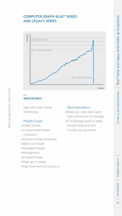
23
RUN
NIN
G M
AN
UA
LTe
naris
Hyd
ril
IDM
Cod
e G
DL2
3353
/1 /
Mar
ch 2
018
TeC
HN
ICA
L Re
Co
MM
eND
ATI
oN
s
Bl
ue® s
erie
s an
d Le
gacy
ser
ies
Mak
e up
Acc
epta
nce Computer Graph Blue® SerieS
and leGaCy SerieS
TOR
QU
E
TURNS
MAX. SHOULDER POINT
MIN. SHOULDER POINT
OPTIMUM TORQUE
UnaccepTable
High and erratic thread
interference.
Possible Causes.Galled threads.Contaminated thread
compound.Incorrect thread compound.Debris on threads.Damaged threads.Misalignment.Crossed threads.High spin in speed.Pipe movement during spin in
Recommendations.Break out, clean and inspect
both connections for damage..If no damage found re-apply
thread compound then
re-make up connection.

24
RUN
NIN
G M
AN
UA
LTe
naris
Hyd
rilTe
cH
NIc
AL
Rec
oM
MeN
dA
TIo
Ns
Bl
ue® s
erie
s an
d Le
gacy
ser
ies
Mak
e up
Acc
epta
nce Computer Graph Blue® SerieS
and leGaCy SerieSTO
RQ
UE
TURNS
MAX. SHOULDER POINT
MIN. SHOULDER POINT
OPTIMUM TORQUE
UnaccepTable
Discontinuous delta torque
build.
Possible Causes .Galled threads.Damaged threads.Misalignment.Crossed threads .Tong slip
Recommendations.Break out, clean and inspect
both connections for damage..If no damage found re-apply
thread compound then
re-make up connection..If tong slip is the cause clean or
replace dies.
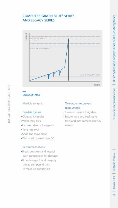
25
RUN
NIN
G M
AN
UA
LTe
naris
Hyd
ril
IDM
Cod
e G
DL2
3353
/1 /
Mar
ch 2
018
TeC
HN
ICA
L Re
Co
MM
eND
ATI
oN
s
Bl
ue® s
erie
s an
d Le
gacy
ser
ies
Mak
e up
Acc
epta
nce Computer Graph Blue® SerieS
and leGaCy SerieS
TOR
QU
E
TURNS
MAX. SHOULDER POINT
MIN. SHOULDER POINT
OPTIMUM TORQUE
UnaccepTable
Multiple tong slip.
Possible Causes.Clogged tong dies.Worn tong dies.Incorrect dies or tong jaws.Tong not level.Snub line movement.Wet or oil covered pipe OD
Recommendations.Break out clean and inspect
both connections for damage..If no damage found re-apply
thread compound then
re-make up connection.
Take action to prevent
reoccurrence.Clean or replace tong dies..Ensure tong and back up is
level and dies contact pipe OD
evenly.

26
RUN
NIN
G M
AN
UA
LTe
naris
Hyd
rilTe
cH
NIc
AL
Rec
oM
MeN
dA
TIo
Ns
Bl
ue® s
erie
s an
d Le
gacy
ser
ies
Mak
e up
Acc
epta
nce Computer Graph Blue® SerieS
and leGaCy SerieSTO
RQ
UE
TURNS
MAX. SHOULDER POINT
MIN. SHOULDER POINT
OPTIMUM TORQUE
UnaccepTable
Discontinuous delta torque
build.
Possible Causes .Coupling turn.Minor yield.External contact on pipe from
other equipment
Recommendations.Break out, clean and inspect
both connections for damage..If no damage found re-apply
thread compound then
re-make up connection..Eradicate any contact from
external equipment.

27
RUN
NIN
G M
AN
UA
LTe
naris
Hyd
ril
IDM
Cod
e G
DL2
3353
/1 /
Mar
ch 2
018
TeC
HN
ICA
L Re
Co
MM
eND
ATI
oN
s
Bl
ue® s
erie
s an
d Le
gacy
ser
ies
Mak
e up
Acc
epta
nce Computer Graph Blue® SerieS
and leGaCy SerieS
TOR
QU
E
TURNS
MAX. SHOULDER POINT
MIN. SHOULDER POINT
OPTIMUM TORQUE
UnaccepTable
Turns counter malfunction.
Recommendations.Break out, clean and inspect
both connections for damage..If no damage found re-apply
thread compound then
re-make up connection..Remedy turns counter
malfunction.

28
RUN
NIN
G M
AN
UA
LTe
naris
Hyd
rilTe
cH
NIc
AL
Rec
oM
MeN
dA
TIo
Ns
Bl
ue® s
erie
s an
d Le
gacy
ser
ies
Mak
e up
Acc
epta
nce

IDM
Cod
e G
DL2
3355
/1 /
Mar
ch 2
018
1
RUN
NIN
G M
AN
UA
LTe
naris
Hyd
rilTe
cH
NIc
AL
Rec
oM
MeN
dA
TIo
Ns
W
edge
™ s
erie
s M
ake
up A
ccep
tanc
eWedge™ Series Make up Acceptance
TenarisHydril Wedge Series 500™ and Wedge Series 600™ connections exhibit substantially different computer graph profiles to those produced by shouldered connections.
Essentially the thread build portion has a smooth ‘ski slope’ transition into linear torque climb as the connection makes up.
TOR
QU
E
TURNS
Operating Torque
Yield Torque
MAXIMUM MAKE UP TORQUE
MINIMUM MAKE UP TORQUE
OPTIMUM MAKE UP TORQUE
Allowabledown holeTorque range
Safety Margin

2
RUN
NIN
G M
AN
UA
LTe
naris
Hyd
rilTe
cH
NIc
AL
Rec
oM
MeN
dA
TIo
Ns
W
edge
™ s
erie
s M
ake
up A
ccep
tanc
e
TOR
QU
E
TURNS
MINIMUM TORQUE
OPTIMUM TORQUE
By design Wedge Series 500™ and Wedge Series 600™ connections do not have the requirement for shoulder torques, if however the computer make up system requires the input of shoulder points, program any appropriate values into the computer.
AcceptAble
Standard profile graph for a Wedge type connection.

3
RUN
NIN
G M
AN
UA
LTe
naris
Hyd
ril
IDM
Cod
e G
DL2
3355
/1 /
Mar
ch 2
018
TeC
HN
ICA
L Re
Co
MM
eND
ATI
oN
s
W
edge
™ s
erie
s M
ake
up A
ccep
tanc
eComputer Graph WedGe SerieS 500™and WedGe SerieS 600™
TOR
QU
E
TURNS
MINIMUM TORQUE
OPTIMUM TORQUE
TOR
QU
E
TURNS
MINIMUM TORQUE
OPTIMUM TORQUE
AcceptAble
The thread build can exhibit a much steeper profile which is equally
acceptable.
AcceptAble
Wedge 623® connections may also exhibit a more distinctive make
up profile such as above.

4
RUN
NIN
G M
AN
UA
LTe
naris
Hyd
rilTe
cH
NIc
AL
Rec
oM
MeN
dA
TIo
Ns
W
edge
™ s
erie
s M
ake
up A
ccep
tanc
e Computer Graph WedGe SerieS 500™and WedGe SerieS 600™
TOR
QU
E
TURNS
OPTIMUM TORQUE
AcceptAble
Minor oscillations during
assembly.
Possible Causes.Pipe movement during spin in..Excessive thread compound
application..Pipe OD contact from external
equipment..Excessive spin in speed.
Recommendations.Reduce quantity of thread
compound applied respecting
application guidelines..Stabilize pipe during make up..Reduce spin in speed.

5
RUN
NIN
G M
AN
UA
LTe
naris
Hyd
ril
IDM
Cod
e G
DL2
3355
/1 /
Mar
ch 2
018
TeC
HN
ICA
L Re
Co
MM
eND
ATI
oN
s
W
edge
™ s
erie
s M
ake
up A
ccep
tanc
eComputer Graph WedGe SerieS 500™and WedGe SerieS 600™
TOR
QU
E
TURNS
MINIMUM TORQUE
OPTIMUM TORQUE
AcceptAble
Tong slip returning to same
thread build path.
Possible Causes.Clogged tong dies..Worn tong dies..Incorrect dies or tong jaws..Tong not level..Snub line movement..Wet or oil covered pipe OD.
Recommendations.Clean or replace dies. .Check tong jaws are correct for
pipe OD. .Ensure tong is level. .Clean pipe OD. .Check snub line.

6
RUN
NIN
G M
AN
UA
LTe
naris
Hyd
rilTe
cH
NIc
AL
Rec
oM
MeN
dA
TIo
Ns
W
edge
™ s
erie
s M
ake
up A
ccep
tanc
e Computer Graph WedGe SerieS 500™and WedGe SerieS 600™
TOR
QU
E
TURNS
MINIMUM TORQUE
OPTIMUM TORQUE
UnAcceptAble
Multiple tong slips.
Possible Causes .Clogged tong dies..Worn tong dies..Incorrect dies or tong jaws..Tong not level..Snub line movement..Wet or oil covered pipe OD.
Recommendations.Break out, clean and inspect
both connections for damage..If no damage found re-apply
thread compound then re-make
up connection.
Take action to prevent
reoccurrence.Clean or replace tong dies..Ensure tong and back up is
level and dies contact pipe OD
evenly.
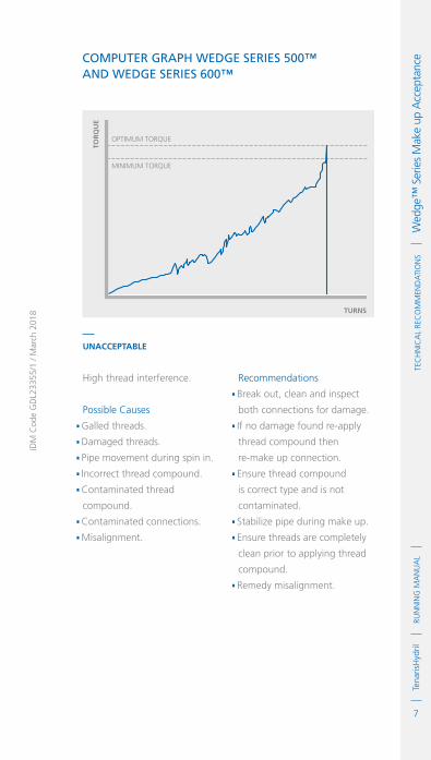
7
RUN
NIN
G M
AN
UA
LTe
naris
Hyd
ril
IDM
Cod
e G
DL2
3355
/1 /
Mar
ch 2
018
TeC
HN
ICA
L Re
Co
MM
eND
ATI
oN
s
W
edge
™ s
erie
s M
ake
up A
ccep
tanc
eComputer Graph WedGe SerieS 500™and WedGe SerieS 600™
TOR
QU
E
TURNS
MINIMUM TORQUE
OPTIMUM TORQUE
UnAcceptAble
High thread interference.
Possible Causes.Galled threads..Damaged threads..Pipe movement during spin in..Incorrect thread compound..Contaminated thread
compound..Contaminated connections..Misalignment.
Recommendations.Break out, clean and inspect
both connections for damage..If no damage found re-apply
thread compound then
re-make up connection..Ensure thread compound
is correct type and is not
contaminated..Stabilize pipe during make up..Ensure threads are completely
clean prior to applying thread
compound..Remedy misalignment.

8
RUN
NIN
G M
AN
UA
LTe
naris
Hyd
rilTe
cH
NIc
AL
Rec
oM
MeN
dA
TIo
Ns
W
edge
™ s
erie
s M
ake
up A
ccep
tanc
e Computer Graph WedGe SerieS 500™and WedGe SerieS 600™
TOR
QU
E
TURNS
MINIMUM TORQUE
OPTIMUM TORQUE
UnAcceptAble
Excessive hump effect.
Possible Causes .Pipe movement during spin in..Incorrect thread compound..Contaminated thread
compound..Running compound not
homogenised..Excessive thread compound..Misalignment.
Recommendations.Break out first two graphs
displaying this profile, clean
and inspect both connections
for damage..If no damage found re-apply
thread compound then
re-make up connection..If no damage found accept
further graphs of similar type..Ensure thread compound
is correct type and is not
contaminated..Reduce quantity of thread
compound applied ensuring all
threads are covered..Stabilize pipe during make up..Ensure threads are completely
clean prior to applying thread
compound..Remedy misalignment.

IDM
Cod
e G
DL2
3356
/1 /
Mar
ch 2
018
1
RUN
NIN
G M
AN
UA
LTe
naris
Hyd
rilTe
cH
NIc
AL
Rec
oM
MeN
dA
TIo
Ns
d
opel
ess®
Tec
hnol
ogy
Mak
e up
Acc
epta
nceDopeless®
Technology Make up Acceptance
TenarisHydril Dopeless® technology is a proprietary technology which removes the requirement for thread compounds to be applied to the connections for assembly.
Dopeless® technology is recognizable on the connections by the surface color:
After make up and break out the appearance of the Dopeless® coating changes appreciably:
Dark Grey White

2
RUN
NIN
G M
AN
UA
LTe
naris
Hyd
rilTe
cH
NIc
AL
Rec
oM
MeN
dA
TIo
Ns
d
opel
ess®
Tec
hnol
ogy
Mak
e up
Acc
epta
nce Dopeless® connections which have been broken out
should be cleaned off with either a clean soft bristle brush or clean rags. This is to remove any excess coating which has ‘balled up’ during assembly. Shiny silver areas will be evident on some parts of the pin connection, this is standard and indicates the high contact areas where the coating has compressed. The box connection will have some of the white coating removed, again this is normal behaviour for Dopeless® connections. As long as no damage has occurred to the connection itself or the coating has not peeled off substantially exposing bare steel, the connections can be re-assembled.
Dopeless® connection graphs generally exhibit similar profiles to those of the doped variant of whichever connection is being assembled. Therefore the graphs indicated in the Make Up Acceptance sections for Blue®, Legacy and Wedge™ Series are also pertinent to the Dopeless® connection. There are however some graph profiles particular to Dopeless® shouldered connections which must be treated differently when witnessed during a Dopeless® technology run.

3
RUN
NIN
G M
AN
UA
LTe
naris
Hyd
ril
IDM
Cod
e G
DL2
3356
/0 /
Mar
ch 2
018
TeC
HN
ICA
L Re
Co
MM
eND
ATI
oN
s
D
opel
ess®
Tec
hnol
ogy
Mak
e up
Acc
epta
nceComputer Graphs Blue® series and leGaCy
series with dopeless® teChnoloGy
TOR
QU
E
TURNS
MAX. SHOULDER POINT
MIN. SHOULDER POINT
OPTIMUM TORQUE
TOR
QU
E
TURNS
MAX. SHOULDER POINT
MIN. SHOULDER POINT
OPTIMUM TORQUE
acceptable
Curved thread and seal interference build with smooth, continuous
profile, no humps or erratic peaks.
acceptable
Plateau prior to shoulder point.

4
RUN
NIN
G M
AN
UA
LTe
naris
Hyd
rilTe
cH
NIc
AL
Rec
oM
MeN
dA
TIo
Ns
d
opel
ess®
Tec
hnol
ogy
Mak
e up
Acc
epta
nce
TOR
QU
E
TURNS
MAX. SHOULDER POINT
MIN. SHOULDER POINT
OPTIMUM TORQUE
Thread and seal interference
build with a smooth, continuous
profile, exhibiting no erratic
or jagged peaks with a hump
higher than shoulder point.
The process to follow when
this type of profile is witnessed:
.Break out the first graph
exhibiting this profile and
inspect for damage..If no damage is found re-make
the connections..Thereafter accept any similar
graph ensuring it displays a
smooth profile.
.

1
RUN
NIN
G M
AN
UA
LTe
naris
Hyd
ril
IDM
Cod
e G
DL2
3358
/1 /
Mar
ch 2
018
TeC
HN
ICA
L Re
Co
MM
eND
ATI
oN
s
C
hrom
e / C
RAChrome / CRA
1. Always handle chrome and CRA steels with due care and attention preventing aggressive contact with carbon steel.
2. Use teflon or plastic drift mandrels when drifting.
3. For chrome and CRA cover pipe racks, storage posts and V-Door with rubber or other soft material to prevent aggressive steel contact when running.
4. Slips, elevators, tong and back up tong jaws should be fitted with low / non-marking non-ferrous dies when running chrome and CRA.
5. Gouging / tearing of pipe body is unacceptable.
6. Maximum die indentations from slips, elevators, and tong jaws should not exceed those indicated in the table below.
0.012"
0.012"
Pipe Body
Coupling
0.009"
0.009"
MAxiMUM inDentAtion DePth
ChRoMe9% - 13%
CRA

2
RUN
NIN
G M
AN
UA
LTe
naris
Hyd
rilTe
cH
NIc
AL
Rec
oM
MeN
dA
TIo
Ns
c
hrom
e / c
RA 7. ensure handling / lift plugs are peened and moly coated prior to use.
8. Use a torque turn monitoring system for all chrome tenarishydril connections.
9. Always use a stabbing guide.
10. Stab pipe in a smooth controlled fashion.
11. Walk pipe all the way in to the hand tight position prior to final make up with a power tong.
12. Walk pipe fully out by hand after initially breaking the connection with a power tong.
13. A weight compensator will assist the walking in / out process.
14. the use of a weight compensator is strongly recommended when running or pulling.
15. Walking chrome pipe in or out by hand is best practice, however there are occasions due to operational set up or regional regulations when it is not possible to do so.
16. in such an instance the pipe can be rotated in or out slowly using the power tong in high gear.
17. Maintain a constant speed during spin in or out not exceeding 5 RPM.
18. Any indication of early torque build during assembly indicates the assembly should be aborted and the connections disassembled, cleaned and inspected.
19. thread compound application is indicated in the product specific running guidelines.

3
RUN
NIN
G M
AN
UA
LTe
naris
Hyd
ril
IDM
Cod
e G
DL2
3358
/1 /
Mar
ch 2
018
TeC
HN
ICA
L Re
Co
MM
eND
ATI
oN
s
C
hrom
e / C
RA20. For non Dopeless® tenarishydril Blue® Series connections ≥ 13% chrome, a thin coat of moly coat spray can be applied on the pin seals and threads.
21. Allow the moly coat to dry prior to applying thread compound.
22. For Wedge Series 500™, Wedge Series 600™, SLx® and MACii™ connections apply a thin coat of moly coat spray to any shiny areas of the pin seals.
23. Allow any application of moly coat to dry prior to applying thread compound.
24. For guidelines on running chrome pipe with CRt equipment, refer to CRt section of this manual.

4
RUN
NIN
G M
AN
UA
LTe
naris
Hyd
rilTe
cH
NIc
AL
Rec
oM
MeN
dA
TIo
Ns
c
hrom
e / c
RA

IDM
Cod
e G
DL2
3359
/1 /
Mar
ch 2
018
1
RUN
NIN
G M
AN
UA
LTe
naris
Hyd
rilTe
cH
NIc
AL
Rec
oM
MeN
dA
TIo
Ns
c
asin
g Ru
nnin
g To
olsCasing Running
Tools
Tenaris do not recommend the make up of any TenarisHydril connection using a rig top drive system unless a calibrated torque sub is used for torque measurement. If the torque sub has no 'in date' calibration a verification test similar to the one indicated below must be performed prior to the commencement of the run.
When using a casing running tool the equipment should have as a minimum the following:.Weight compensator.Torque sub .Torque turn computer capable of indicating torque turns.Computer capable of a minimum sample rate of 500 pulses per turn
Both torque sub and computer equipment must have valid calibration certificates, in the absence of these a torque calibration test should be conducted in order to verify the torque indicated is the actual torque applied.
TORQUE SUB
CALIBRATED LOAD CELL
COMPUTER
NOTE: VErify ThE TOrquE rEadiNg frOm TOrquE sub TO
cOmpuTEr cOrrEspONds TO ThaT iNdicaTEd by ThE lOad cEll.

2
RUN
NIN
G M
AN
UA
LTe
naris
Hyd
rilTe
cH
NIc
AL
Rec
oM
MeN
dA
TIo
Ns
c
asin
g Ru
nnin
g To
ols 1. Verify turn measurement is accurate by scribing
a line vertically down the pipe and visually verifying against 1 turn indicated by the equipment.
2. Ensure alignment of the system is as close to the well bore as possible, alignment is critical for normal running operations and even more so when using a CRT type tool. Adjust any misalignment prior to first make up. Misalignment will cause issues with connection assembly.
Misalignment may also cause damage to the box face, threads and connection ID / OD when grapples are inserted / extracted which may be detrimental to connection and / or pipe performance.
3. Torque applied should be verified on the calibrated computer, not from the driller’s torque gauge.
4. Make up rotation should not exceed 10 RPM at any time, reducing to below 5 RPM for final turn.
5. Utilize handling plugs or open end thread protectors in the box connection to protect threads and seals from grapple damage during insertion / extraction.
6. Ensure weight compensator is activated and functioning correctly.
7. Check for excessive grapple damage to pipe body or connection.
8. Ensure grapple is unset completely prior to removal from pipe to prevent gouging.

3
RUN
NIN
G M
AN
UA
LTe
naris
Hyd
ril
IDM
Cod
e G
DL2
3359
/1 /
Mar
ch 2
018
TeC
HN
ICA
L Re
Co
MM
eND
ATI
oN
s
C
asin
g Ru
nnin
g To
ols
Damage inflicted to face and
torque shoulder of a coupling
during insertion of CRT
grapples.
The photographs below are of damage caused by misaligned CRT equipment.

4
RUN
NIN
G M
AN
UA
LTe
naris
Hyd
rilTe
cH
NIc
AL
Rec
oM
MeN
dA
TIo
Ns
c
asin
g Ru
nnin
g To
ols
Care must be taken by the CRT operator to ensure correct alignment of the equipment and to ensure the grapples are set / unset correctly prior to operating.
Ensure grapple is set on pipe body ID / OD, depending on type used, and not over connections.
Gouging on pipe ID and across
the coupling central area by
insertion / removal of grapples.

5
RUN
NIN
G M
AN
UA
LTe
naris
Hyd
ril
IDM
Cod
e G
DL2
3359
/1 /
Mar
ch 2
018
TeC
HN
ICA
L Re
Co
MM
eND
ATI
oN
s
C
asin
g Ru
nnin
g To
ols
Die indentations on the ID of
a handling plug indicating the
grapples were set across the
connection area.
Chrome
.The use of a CRT tool to run chrome pipe is not recommended due to the heightened risk of inflicting damage to the connections and / or pipe body.
.If a CRT tool is used to run chrome pipe, attention to detail and adherence to best practices is of paramount importance.
.It is imperative the CRT tool is accurately aligned with the pipe set in the rotary, alignment is acutely critical when running chrome but even more so when using a CRT tool. This is mainly due to two issues; chrome is by its nature more susceptible to galling than standard carbon steels. A CRT tool holds the pipe rigidly at the top preventing any natural movement during rotation which can assist in alleviating minor misalignment, pipe bend or rig movement. Therefore if alignment is not accurate when running chrome the potential for thread galling as the connection assembles is far greater.

6
RUN
NIN
G M
AN
UA
LTe
naris
Hyd
rilTe
cH
NIc
AL
Rec
oM
MeN
dA
TIo
Ns
c
asin
g Ru
nnin
g To
ols .Chrome pipe has to be treated with greater care
and attention than carbon steels to prevent material damage. If the CRT is misaligned the potential for damage to the connections and pipe bodies is greatly increased as the grapples are positioned / removed.
.The CRT equipment must have a weight compensator to assemble chrome pipe.
.Walking the pipe all the way in to the hand tight position is best practice when running chrome pipe. This ensures the threads are not crossed at stabbing, however this may not be possible when using a CRT.
.If it is not possible to walk the pipe in, rotate the pipe in 1 full revolution by hand immediately after stabbing and prior to grapple positioning, the pipe can then be assembled using the CRT.
.Rotate the pipe constantly at ≤ 5 RPM after the initial hand rotation.
.Reduce make up rotation to ≤ 4 RPM for final make up.
.During running it is good practice to constantly check indentation marks created by the grapples on the pipe ID / OD. Ensure indentations are not excessive and no slipping of the grapples has occurred resulting in gouging of the pipe body.
.Check the grapples are not being set too high across the connection.

IDM
Cod
e G
DL2
3468
/1 /
Mar
ch 2
018
1
RUN
NIN
G M
AN
UA
LTe
naris
Hyd
rilTe
cH
NIc
AL
Rec
oM
MeN
dA
TIo
Ns
H
oriz
onta
l Ass
embl
yHorizontalAssembly
When assembling accessories, shoe tracks and other such assemblies the application of good practices will ensure successful horizontal make up of the product.
Bucking unit
1. Check torque gauge, load cell and computer equipment have valid calibration certification.
2. Check unit is level, place a pup joint / pipe in the unit, check alignment along all 3 axis with a spirit level, adjust if necessary.
3. Check condition of tong dies in both rotating head and back up, these should be clean, in good condition and sharp. Poor quality dies will slip and create tears and / or gouging of the steel surface.
4. Non / low marking dies should be used for chrome material.
5. Check and note configuration of tong jaws ensuring symmetrical circumferential grip on OD. Ideally tong jaws should be configured to spread the compressive load round the OD to prevent deformation of the part gripped.
6. If the unit is of the skid type, special care should be taken in leveling the unit along all 3 axis.

2
RUN
NIN
G M
AN
UA
LTe
naris
Hyd
rilTe
cH
NIc
AL
Rec
oM
MeN
dA
TIo
Ns
H
oriz
onta
l Ass
embl
y
7. If the unit is of the type which has a bull tong as a back up with the load cell attached, ensure the back up arm length is input to the computer as this arm length will indicate the applied force measurement.
8. The tong arm snub line to which the load cell is attached should be at right angles to the tong arm, ± 15°, to ensure correct force is applied and recorded.
9. Ensure one of the tong heads is free floating and capable of natural movement along both ‘X’ and ‘Y’ axis to allow smooth assembly of the connections.
10. Computer make up equipment with the capability of torque turn measurement and a minimum of 500 pulses per turn should always be used when assembling horizontally.
11. Computer graph acceptance criteria is the same as that for running pipe.
Z
X
Y
BUCKING UNIT
Level bucking unit along 3 axis.

3
RUN
NIN
G M
AN
UA
LTe
naris
Hyd
ril
IDM
Cod
e G
DL2
3468
/1 /
Mar
ch 2
018
TeC
HN
ICA
L Re
Co
MM
eND
ATI
oN
s
H
oriz
onta
l Ass
embl
yTorque Values Wedge Series 500™and Wedge Series 600™
When making up any doped Wedge series connection horizontally add 20% to the indicated optimum torque. Relax the tongs, scribe a line across the assembled connections then re-apply optimum torque plus 20% 'double bump'. If the line moves less than ½" accept the assembly, if the line moves more than ½" check and rectify any variables which may absorb torque then repeat the process.
For buck on of Wedge Series 500™ and Wedge Series 600™ couplings, torque values corresponding to the buck on torques detailed in the TenarisHydril connection datasheet should be applied. The additional 20% is not necessary for couplings as the buck on torques are higher than standard optimum torque applied to the field end. If movement above ½" is witnessed after re-applying buck on torque, apply maximum buck on torque, relax the tong and repeat.
Except for couplings, any wedge series connection assembled horizontally requires 20% additional torque added to the optimum and 'double bump'. For couplings only, apply buck on torque and 'double bump'.
For Dopeless® connections add 20% to the indicated optimum torque, however it is not necessary to apply the torque twice.
Torque Values Blue® Series,Legacy Series and TenarisXP® Buttress
As a general rule, the shoulder torque of a Blue® Series, Legacy Series and TenarisXP® Buttress connection depends on the contact pressure generated between threads and seal. If there is a large change in the OD or ID of the connection an increase in the shoulder torque value may be observed. For example, larger OD box

4
RUN
NIN
G M
AN
UA
LTe
naris
Hyd
rilTe
cH
NIc
AL
Rec
oM
MeN
dA
TIo
Ns
H
oriz
onta
l Ass
embl
y connections such as running tools or hangers will often result in an increased shoulder point during make up. For this reason it is advisable to check with Tenaris to validate if an adjustment in torque is required. If making up a connection with a larger OD or smaller ID than standard for the connection the following information should be provided:.Assembly schematics .Item configuration.OD and ID.Material grades
For coupling buck on and all other accessory make up of Blue® Series, Legacy Series and TenarisXP® Buttress connections, field make up torque values detailed in the datasheet are to be used.
If a connection is found to have a poor make up graph it must be backed out fully, both connections cleaned and inspected for damage.
Horizontal Pre-Assembly
In certain regions it is common practice to assemble stands of range 2 or range 3 pipe horizontally prior to shipping to the rig site. If this process is utilized it is imperative the following guidelines are applied:If Wedge Series 500™ and Wedge Series 600™ connections are to be assembled:
1. It is imperative the connections are not over doped as this can absorb applied torque resulting in a connection which is incorrectly assembled.
2. Always apply optimum torque plus 20%.
3. Always relax tong and re-apply optimum torque plus 20%.

5
RUN
NIN
G M
AN
UA
LTe
naris
Hyd
ril
IDM
Cod
e G
DL2
3468
/1 /
Mar
ch 2
018
TeC
HN
ICA
L Re
Co
MM
eND
ATI
oN
s
H
oriz
onta
l Ass
embl
y4. Any movement above ½" relax tongs then apply optimum torque plus 30%.
5. Scribe a longitudinal line across the assembled connections with an indelible marker indicating make up point. This allows a quick visual indicator if any back off occurs during handling and transportation. 6. On Wedge 563®, 521®, 553® or 625® connections ensure the box face is within the lower and upper lines of the make up band.
7. The re-application of torque is unnecessary for Dopeless® connections.
When moving assembled doubles ensure sling placement is as below:
20ft ± 3ft20ft ± 3ft
Preparation
As with all connections any accessories being assembled should be cleaned of all thread compounds ensuring the connection is clean, dry and free of any damage prior to applying appropriate thread compound or thread lock.
HORIZONZAL PRE-ASSEMBLY
Sling placement for pipe stands.

6
RUN
NIN
G M
AN
UA
LTe
naris
Hyd
rilTe
cH
NIc
AL
Rec
oM
MeN
dA
TIo
Ns
H
oriz
onta
l Ass
embl
y Apply Tenaris approved thread compound or API equivalent as advised in the specific connection running guideline. If thread lock compound is to be applied this should also be done in accordance with the connection specific running guideline. It is also good practice to visibly identify, with paint if possible, which connections are thread locked for ease of identification at the rig site.
Connection Engagement
After ensuring both connections to be made up are true and level in the bucking unit and completely aligned with each other, make the connections up as far as possible by hand utilizing a chain tong or strap wrench. Once the connections are hand tight apply rotation with the bucking unit in low gear ensuring rotation speed is between 2 and 5 RPM.
If a long accessory or full length joint has to be made up ensure the joint / accessory / assembly is fully supported along the entire length of the item preventing sag, as this can result in misalignment and erratic make up behavior due to a fulcrum effect.
MINIMALOVERHANG
A B
CORRECTLY SUPPORTEd ITEM
Without support ‘B’ the item
would tilt down at the overhang.
Support ‘A’ would act as a
fulcrum on the tong head.

7
RUN
NIN
G M
AN
UA
LTe
naris
Hyd
ril
IDM
Cod
e G
DL2
3468
/1 /
Mar
ch 2
018
TeC
HN
ICA
L Re
Co
MM
eND
ATI
oN
s
H
oriz
onta
l Ass
embl
y
GRIP
COUPLING
BREAK OUT
Grip coupling at centre or field
end when making or breaking.
Ensure that the tong jaws are not situated over the threaded area of the box connection being assembled. This will compress the OD of the connection creating higher contact pressures which may lead to high shoulder and / or galled connections.
Break Out
When breaking out any connection use the tong to make initial break and one full rotation then use a chain tong or strap wrench to fully disengage the connections.
Ensure the item is fully supported and aligned along its entire length, this prevents any thread damage due to sag and misalignment as the item disengages.
Ensure the jaws do not grip the coupling over the pin end being broken out as this will create high contact pressure during break out due to the compressive forces applied and can result in damage to both connections.

8
RUN
NIN
G M
AN
UA
LTe
naris
Hyd
rilTe
cH
NIc
AL
Rec
oM
MeN
dA
TIo
Ns
H
oriz
onta
l Ass
embl
y

IDM
Cod
e G
DL2
3361
/1 /
Mar
ch 2
018
1
RUN
NIN
G M
AN
UA
LTe
naris
Hyd
rilTe
cH
NIc
AL
Rec
oM
MeN
dA
TIo
Ns
Ru
nnin
g, P
ullin
g an
d Ra
ckin
g Pi
pe in
sta
ndsRunning, Pulling
and Racking Pipein Stands
In order to ensure performance continuity of the Tenaris product and connections whilst being racked, run and pulled in stands of two or three pipe, the following recommendations are applicable to all TenarisHydril premium connections.
Flush, Near Flush and Blue® Riser connections, by their very design, are more susceptible to damage from impact and pressure acting on the thinner wall of the pin nose when racked in stands. Damage can be caused by incorrect or poorly fitted protectors, uneven / hard stand back area, rough handling resulting in high impact when setting stands down on stand back area, side loading created by non-vertical racking and cyclical loading on the pin nose created by rig movement during adverse weather. For these reasons there is a higher risk of damage being inflicted on thin walled flush or near flush connections, this risk increases relative to the OD of the pipe but can be minimized by studiously applying these guidelines. If any doubt exists on racking pipe in the derrick please contact Tenaris for further analysis.
Initial Running Guidelines
1. Once delivered to the rig the pipe should be visually inspected for any obvious handling damage to pipe bodies.
2. Drifting of the pipe if completed on location should be carried out from box to pin end.

2
RUN
NIN
G M
AN
UA
LTe
naris
Hyd
rilTe
cH
NIc
AL
Rec
oM
MeN
dA
TIo
Ns
Ru
nnin
g, P
ullin
g an
d Ra
ckin
g Pi
pe in
sta
nds 3. Connections should be cleaned and inspected then
have clean, dry thread protectors re-installed.
4. All protectors should be left securely in place until the pipe is at the rig floor just prior to running.
5. When protectors are removed they must be stored in such a manner as to prevent debris or fluid contaminating them.
6. When removing Dopeless® protectors ensure the rubber seal rings have not remained attached to the pin or box connections.
7. When transporting the pipe to the V-Door care should be taken to prevent damage being inflicted on the connections.
8. During the initial run the recommended running and make up practices as indicated in the TenarisHydril Running Manual should be implemented.
9. When running stands, it is imperative that the torque of each connection is checked by applying specified optimum torque.
10. For Wedge Series 500™ and Wedge Series 600™ connections:.If rotation of the connection is witnessed relax the tong once optimum torque has been attained scribe a line across the pin and box connections then re-apply optimum torque. .If rotation of more than ½” is witnessed upon the second application of optimum torque proceed as follows:.Re-apply optimum torque + 20%. .For Dopeless® connections apply optimum torque once.
For non-wedge connections: .If any rotation of the connection is witnessed when applying optimum torque, break out completely and inspect. .If the connection is OK re-make using optimum torque.

3
RUN
NIN
G M
AN
UA
LTe
naris
Hyd
ril
IDM
Cod
e G
DL2
3361
/1 /
Mar
ch 2
018
TeC
HN
ICA
L Re
Co
MM
eND
ATI
oN
s
Ru
nnin
g, P
ullin
g an
d Ra
ckin
g Pi
pe in
sta
ndsPulling Stands
1. If possible prior to pulling the string it would be beneficial to pump 10 barrels of fresh water into the string above the high viscosity pill in order to flush hole fluid from the pipe ID.
2. As the stand is pulled excess hole fluid should be wiped from the OD with a wiper.
3. As the stands are POOH scribe an indelible paint mark across the connections, to be used as a visual verification aid during RIH that no movement of either field or mill end make up has occurred.
4. Once initial break is achieved the connection should be rotated out at 5 RPM or slower ensuring no excessive pipe movement or sway is induced to the stand during rotation. If pipe sway or wobble does occur cease rotation immediately.
5. Do not allow the connection to ‘bounce’ heavily on disassembly, count the turns from break and slow rotation at final turn.
6. Once fully rotated out the stabbing guide should be placed over the connection to assist centralization of the pin connection and prevent thread hang up.
7. The stand should be lifted out of the box slowly.
8. When disconnected, the pin and box connections should be rinsed with fresh water, dried and inspected. If no damage is witnessed clean dry protectors must be securely installed.

4
RUN
NIN
G M
AN
UA
LTe
naris
Hyd
rilTe
cH
NIc
AL
Rec
oM
MeN
dA
TIo
Ns
Ru
nnin
g, P
ullin
g an
d Ra
ckin
g Pi
pe in
sta
nds 9. With the exception of Dopeless® connections ensure
all threads and seal areas are adequately covered with thread compound.
10. Open ended pin protectors should be installed on the pin end to allow the egress of any corrosive fluid from the pipe ID.
11. For Dopeless® connections the correct Dopeless® protectors must be used, ensuring the rubber seal rings are correctly in place.
12. Thread protectors can shatter or split with the extra weight of a stand bearing down upon them. For stands of three or heavy pipe use either open end composite thread protectors or stand back protectors designed for this type of operation. Dopeless® connections should always have the correct Dopeless® protectors installed, open ended to allow the egress of fluid.
13. When racking back, the stands should be secured as vertically as possible in order to prevent sag or excessive pipe movement due to rig heave / pitch / roll / strong wind.

5
RUN
NIN
G M
AN
UA
LTe
naris
Hyd
ril
IDM
Cod
e G
DL2
3361
/1 /
Mar
ch 2
018
TeC
HN
ICA
L Re
Co
MM
eND
ATI
oN
s
Ru
nnin
g, P
ullin
g an
d Ra
ckin
g Pi
pe in
sta
nds
14. If the pipe stands are seen to be suffering excessive movement due to heave / pitch / roll / strong wind then a support band should be secured round the middle of the stands between the rig floor and the derrick racking fingers. This band should be of rope or other such soft material, under no circumstances should wire slings, hawsers or winch lines be used round the pipe.
Stands racked vertically
preventing sag / bending.

6
RUN
NIN
G M
AN
UA
LTe
naris
Hyd
rilTe
cH
NIc
AL
Rec
oM
MeN
dA
TIo
Ns
Ru
nnin
g, P
ullin
g an
d Ra
ckin
g Pi
pe in
sta
nds 15. When racking back, the stands should be lowered
onto a wooden stand back area slowly in order to prevent the protectors fracturing or crossing. A wooden stand back area is recommended to prevent pin protector shatter. Additionally special racking protectors can be used for stands of pipe.
16. On every second POOH the connection breaks should be rotated by breaking off the top joint, cleaning and protecting the connections and laying on deck to be RIH first on next run or made up to the last stand POOH.
17. A weight compensator is recommended when pulling stands of pipe.
Running in Stands 1. Once the stand is picked up and the pin protector removed, the connections should be wiped clean of excess fluid then inspected for damage or corrosion.
2. Any connection damage witnessed should be repaired as per Tenaris field repair guidelines by a qualified Tenaris representative.
3. If it is found a connection is incapable of being repaired the joint should be laid out.
4. All damaged connections should be cleaned and dried then have storage compound applied prior to clean dry protectors being installed securely.
5. The rejected connection should be identified by a red paint band round the OD and the pipe segregated to ensure it is not picked up again.

7
RUN
NIN
G M
AN
UA
LTe
naris
Hyd
ril
IDM
Cod
e G
DL2
3361
/1 /
Mar
ch 2
018
TeC
HN
ICA
L Re
Co
MM
eND
ATI
oN
s
Ru
nnin
g, P
ullin
g an
d Ra
ckin
g Pi
pe in
sta
nds6. It is imperative when rotating stands they do not
exhibit excessive wobble or movement, ideally stands should be stabilized when rotating. Stabilization is critical during strong winds and / or heavy rig movement.
7. A stabbing guide must be used every time a stand or single joint is stabbed or disconnected.
8. During an initial run of pre-assembled stands the torque of every connection should be checked by applying indicated optimum torque.
9. It is advisable that the torque of each connection is checked every RIH to ensure no back off occurs whilst the stands are racked in the derrick.
10. Visually verify connection rotation has not occurred whilst stands have been racked by checking the line scribed across connections during previous POOH. Any suspicion of possible movement should be checked.
11. A weight compensator is recommended when running stands of pipe.
Stabilization of Stand during
make up and break out.

8
RUN
NIN
G M
AN
UA
LTe
naris
Hyd
rilTe
cH
NIc
AL
Rec
oM
MeN
dA
TIo
Ns
Ru
nnin
g, P
ullin
g an
d Ra
ckin
g Pi
pe in
sta
nds Breaking Down and Laying Out
1. When breaking down the stands to lay out in singles, the process as indicated for pulling stands should be applied, ensuring all connections are thoroughly cleaned of corrosive fluid and protected by applying storage compound to both pin and box on non Dopeless® connections, then securely installing clean, dry thread protectors.
2. Do not apply storage compound to Dopeless® connections, if possible dry the connections prior to installing clean, dry protectors.
3. Ensure Dopeless® protectors with seal rings correctly in place are installed on Dopeless® connections.
4. All pipe should be cleaned thoroughly to remove all corrosive fluids and inspected as soon as possible upon return to logistics base or yard to prevent corrosion rejects.
Corrosion Barrier / Fiber Glass Lined
1. If the connections are of the Corrosion Barrier (CB®) or FGL variants ensure the CB® rings are removed and discarded each time the pipe is pulled. A new ring should be installed for every make up.
2. Inspect the CB® ring groove for damage, corrosion and cleanliness (refer to section 10).

IDM
Cod
e G
DL2
3362
/1 /
Mar
ch 2
018
1
RUN
NIN
G M
AN
UA
LTe
naris
Hyd
rilTe
cH
NIc
AL
Rec
oM
MeN
dA
TIo
Ns
FG
L an
d c
B® o
ptio
nsFGL and CB® Options
These guidelines only apply to connections listed in the table below with the Corrosion Barrier (CB®) or Fiber Glass Lined (FGL) option.
Compatibility
The compatibility of connections with CB® or FGL with standard connections is indicated below:
CONNECTIONS
TSH BLuE-FGL
TSH BLuE-CB
TSH MS-FGL
TSH MS-CB
TSH WEDGE 563-CB
TSH WEDGE 553-CB
TSH WEDGE 533-CB
TSH PH4-CB
TSH PH6-CB
TSH CS-CB
TSH PJD-CB
No
No
No
No
Yes
Yes
Yes
Yes
Yes
Yes
Yes
CONNECTIONS COMPaTIBLE WITH STaNDarD OPTION
accessories
accessories for FGL or CB® options are specially designed by Tenaris, the only accessories that should be used are those threaded by Tenaris or one of its licensed repair shop facilities.

2
RUN
NIN
G M
AN
UA
LTe
naris
Hyd
rilTe
cH
NIc
AL
Rec
oM
MeN
dA
TIo
Ns
FG
L an
d c
B® o
ptio
ns Drifting
1. The use of a non metallic drift is advisable in order to prevent damage to the coating and / or flanges.
2. For FGL lined pipe, the drift diameter is substantially smaller. In certain instances this is also true of internal plastic coated pipe. Check that the drift mandrel is correct for the pipe / connection ID including the coating / liner.
Inspection
The inspection of FGL or CB® option type connections is the same as that for the standard variant of the connection. Special attention must however be paid to the coating or end flange for FGL. Never run a pipe with damaged coating or damaged fiberglass lining. any damage to the coating or lining must be repaired either by the coating company or by certified personnel of a third party company. If either are unavailable the joint must be segregated and clearly identified.
Installation of Seal rings
1. Check the available seal rings are the specific ones for the product to be run. Ensure there are additional seal rings available. Install the seal rings just before running the pipe either at the V-Door or at the rig floor. Do not install them on the pipe racks.
2. Make sure seal rings and pipe are at the same temperature before installation. Fully clean and dry box end connection and perform a visual thread inspection.
3. Check there are no seal rings already installed on the connection. any seal rings already installed must be removed and discarded before installing a new one.

3
RUN
NIN
G M
AN
UA
LTe
naris
Hyd
ril
IDM
Cod
e G
DL2
3362
/1 /
Mar
ch 2
018
TeC
HN
ICA
L Re
Co
MM
eND
ATI
oN
s
FG
L an
d C
B® o
ptio
ns4. Make sure the seal ring is in perfect condition before installing, free from cuts, deformation or dents. If the seal ring is not in perfect condition it must be discarded.
Blue® Series and MS™ FGL
1. Take a brand new seal ring and compress it with the fingers so that it partially collapses into the inside diameter of the pipe.
CB® AND FGL SEAL RING
Manually collapse the seal ring.
2. Place collapsed seal ring into the box seal ring groove and release it.
3. Make sure the "T" end of the seal ring fits into the gap between the flange and the ID of the coupling.
4. Manually push the seal ring into place, pressing all around the edge of the ring. You can use a non-metallic instrument like a wooden hammer handle to nudge it into place.
5. Make sure the seal ring is properly seated between the flange (the front of the pin) and the ID of the coupling. The seal ring must be in contact with the ID of the coupling all the way round and should not stick out at any point. If in doubt, use a straight edge to check whether it is properly aligned.
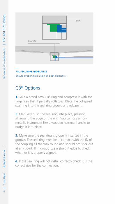
4
RUN
NIN
G M
AN
UA
LTe
naris
Hyd
rilTe
cH
NIc
AL
Rec
oM
MeN
dA
TIo
Ns
FG
L an
d c
B® o
ptio
ns
CB® Options
1. Take a brand new CB® ring and compress it with the fingers so that it partially collapses. Place the collapsed seal ring into the seal ring groove and release it.
2. Manually push the seal ring into place, pressing all around the edge of the ring. You can use a non-metallic instrument like a wooden hammer handle to nudge it into place.
3. Make sure the seal ring is properly inserted in the groove. The seal ring must be in contact with the ID of the coupling all the way round and should not stick out at any point. If in doubt, use a straight edge to check whether it is properly aligned.
4. If the seal ring will not install correctly check it is the correct size for the connection.
FGL SEAL RING AND FLANGE
Ensure proper installation of both elements.
box
flange

5
RUN
NIN
G M
AN
UA
LTe
naris
Hyd
ril
IDM
Cod
e G
DL2
3362
/1 /
Mar
ch 2
018
TeC
HN
ICA
L Re
Co
MM
eND
ATI
oN
s
FG
L an
d C
B® o
ptio
ns
running Compound application
1. apply the running compound to connections with the CB® option as indicated in the specific product running guideline.
2. apply the running compound to connections with the FGL option as indicated in the product specific running guideline, do not however apply running compound on the pin nose and flange.
TSH WEDGE 533-CB TSH WEDGE 563-CB
Cb ring
box
pin

6
RUN
NIN
G M
AN
UA
LTe
naris
Hyd
rilTe
cH
NIc
AL
Rec
oM
MeN
dA
TIo
Ns
FG
L an
d c
B® o
ptio
ns

IDM
Cod
e G
DL2
3366
/1 /
Mar
ch 2
018
1
RUN
NIN
G M
AN
UA
LTe
naris
Hyd
rilTe
cH
NIc
AL
Rec
oM
MeN
dA
TIo
Ns
Pi
pe Id
entif
icat
ionPipe Identification
Marking Premium Threaded Pipe
HARD STAMP / STENCIL COUPLING
.TTM: TenarisTamsa.5CT: API specification.0124: API license number.4/1: 2004 Q1.SF: Special end-finish.53.5: Mass designation.P: Grade.S: Seamless.TSH MS: Thread type
PIPE STENCIL
.Manufacturer .Manufacturing specification.API monogram.Date of manufacture.Special end finish.Outside Diameter.Mass designation.Grade.Process of manufacture.Hydrostatic test pressure.Drift diameter if alternative drift.Thread type.Customer brand / PO number.Heat number.Pipe number.Length (mts)

2
RUN
NIN
G M
AN
UA
LTe
naris
Hyd
rilTe
cH
NIc
AL
Rec
oM
MeN
dA
TIo
Ns
Pi
pe Id
entif
icat
ion
__
NOTE: THE PIPE MARKING SHOWN IS ONLY AN EXAMPLE.
SOME DIFFERENCES MAY BE OBSERVED DEPENDING ON WHERE
PRODUCTS ARE MANUFACTURED.
Tenaris mills marking codes
Facility Stenciling code
die Stamping code
tenariS aberdeen
tenariS algoma
tenariS bakerSField
tenariS batam
tenariS conFab
tenariS conroe
tenariS counce
tenariS dalmine
tenariS machachi
tenariS eSbjerg
tenariS hickman
tenariS mccarty
tenariS niSku
tenariS nkktubeS
tenariS prudential
tenariS Qingdao
tenariS Saudi arabia
tenariS Siat Valentín alSina
tenariS Siat Villa conStitución
tenariS Siderca
tenariS Silcotub
tenariS Spij
tenariS tamSa
tenariS texaS
tenariS tubo caribe
tenariS WeStWego
tenariS onne
tenariS Warri
tenariS baycity
tenariS aktau
tenariS FaSt
tenariS ab
tenariS at
tenariS bk
tenariS bt
tenariS cF
tenariS cr
tenariS cn
tenariS dl
tenariS ma
tenariS eS
tenariS hk
tenariS mc
tenariS hn
tenariS nk
tenariS pS
tenariS Qd
tenariS Sa
tenariS Va
tenariS Vc
tenariS Sd
tenariS Sl
tenariS ij
tenariS tm
tenariS ta
tenariS tc
tenariS WW
tenariS on
tenariS Wa
tenariS bc
tenariS ak
tenariS FS
tab
tat
tbk
tbt
tcF
tcr
tcn
tdl
tma
teS
thk
tmc
thn
tnk
tpS
tQd
tSa
tVa
tVc
tSd
tSl
tij
ttm
tta
ttc
t WW
ton
tWa
tbc
tak
tFS

3
RUN
NIN
G M
AN
UA
LTe
naris
Hyd
ril
IDM
Cod
e G
DL2
3366
/1 /
Mar
ch 2
018
TeC
HN
ICA
L Re
Co
MM
eND
ATI
oN
s
Pi
pe Id
entif
icat
ionMarking API Threaded Pipe
HARD STAMP/STENCIL COUPLING
.TAT: TenarisAlgoma.5CT: API specification.8/1: 2008 Q1.53.5: Mass designation.P: Grade.S: Seamless
PIPE STENCIL
.Manufacturer.Manufacturing specification.API monogram.Date of manufacture .Outside Diameter.Mass designation.Grade.Process of manufacture.Hydrostatic test pressure.Thread type.Drift diameter if alternative drift.Customer brand.Heat number.Pipe number.Length (mts)

4
RUN
NIN
G M
AN
UA
LTe
naris
Hyd
rilTe
cH
NIc
AL
Rec
oM
MeN
dA
TIo
Ns
Pi
pe Id
entif
icat
ion
Bundle# 0600133804
THK 224419 9 1/2 20 F110/CTSH BLUE DPLS-SC
DIGITALTALLY
PipeTracer™
PipeTracer™ is a specialized tracking and traceability tool that allows instant identification of Tenaris products on-site with a mobile device. By scanning mill applied codes located on the pipe body and / or thread protectors, it is possible to obtain technical and dimensional information from each pipe to create a digital running tally. A unique pipe reference code (URC) is included on each individual pipe.
MARKING TECHNOLOGY
THReAD PROTeCTORS (**)
datamatrixidentiFication ring
linear datamatrix urc code
rFid & label on protectorS
BUnDLe LABeL wITH RFID
95751125 0807
TTM 034295 9 5/B 404 TN
95CR13 MTSH BLU
E DPLS-SC
BLUEBAND
(*) Type of marking may vary dependingon manufacturing facility.
(**) RFID protectors are not always available.
PIPe BODy (*)

5
RUN
NIN
G M
AN
UA
LTe
naris
Hyd
ril
IDM
Cod
e G
DL2
3366
/1 /
Mar
ch 2
018
TeC
HN
ICA
L Re
Co
MM
eND
ATI
oN
s
Pi
pe Id
entif
icat
ionPipe Grade Identification
Pipe manufacturers apply color bands to the pipe body and couplings to help identify different steel grades from a distance.
In addition to color bands, the stencils on the pipe body and couplings provide information on the tubular product and its manufacturing process (e.g; dimensions, material, threaded connection, test pressure, if seamless or welded, manufacturing mill, heat number, etc.).__
THE COLOUR CODES IN THIS SECTION ARE FOR GUIDENCE PURPOSES
ONLY, ANY CHANGES MAY NOT BE UPDATED.
NOTE: COLOUR BANDS MAY ALSO BE APPLIED ACCORDING TO CUSTOMER
SPECIFICATIONS. THE TABLES GIVEN BELOW DO NOT APPLY TO THESE CASES.
COLOR CODES FOR API GRADES
black
–
White
–
brown
–
–
–
–
–
–
–
–
–
–
–
bright green
bright green
bright green
red
black
bright green
bright green
bright green
bright green
–
–
–
bright green
blue
–
–
–
–
–
–
–
–
–
–
(*) Optional: bare. None or black bands at the manufacturer's option.(**) Special-clearance coupling also has a black band in the centre of the coupling. Seal ring couplings shall also have a blue band.
STEEL GRADES COUPLING (**) PIPE BODY
BandsBody Bands
2 nd.1 st. 3 rd. 1 st. 2 nd. 3 rd. 4 th.
H40 (*)
J55 (tubing)
J55 (casing)
K55
M65

6
RUN
NIN
G M
AN
UA
LTe
naris
Hyd
rilTe
cH
NIc
AL
Rec
oM
MeN
dA
TIo
Ns
Pi
pe Id
entif
icat
ion
(**) Special-clearance coupling also has a black band in the centre of the coupling. Seal ring couplings shall also have a blue band.
STEEL GRADES COUPLING (**) PIPE BODY
BandsBody Bands
2 nd.1 st. 3 rd.
–
green
–
brown
yellow
yellow
–
–
brown
–
–
–
–
–
–
yellow
–
–
–
brown
–
–
–
–
–
–
–
–
–
–
–
–
–
red
red
brown
red
–
–
purple
Silver
White
White
orange
1 st. 2 nd. 3 rd. 4 th.
red
red
brown
red
red
red
purple
Silver
White
White
orange
–
bright green
–
brown
brown
brown
–
–
brown
–
–
–
–
–
–
yellow
yellow
–
–
brown
–
–
–
–
–
–
yellow
–
–
–
–
–
–
N80 Type 1
N80Q
R95
L80 Type 1
L80 Type 9Cr
L80 Type 13Cr
C90 Type 1
T95 Type 1
C110
P110
Q125 Type 1

7
RUN
NIN
G M
AN
UA
LTe
naris
Hyd
ril
IDM
Cod
e G
DL2
3366
/1 /
Mar
ch 2
018
TeC
HN
ICA
L Re
Co
MM
eND
ATI
oN
s
Pi
pe Id
entif
icat
ionCOLOR CODES FOR PROPRIETARY GRADES
blue
purple
orange
Silver
pink
blue
blue
purple
orange
orange
pink
–
–
Skyblue
–
yellow
blue
–
–
Skyblue
–
pink
brown
brown
brown
brown
brown
brown
pink
pink
pink
White
yellow
blue
purple
orange
Silver
pink
blue
blue
purple
orange
White
pink
brown
brown
Skyblue
brown
yellow
blue
pink
pink
Skyblue
orange
yellow
–
–
brown
–
brown
brown
–
–
pink
–
pink
TN 80SS
TN 90SS
TN 95SS
TN 100SS
TN 110SS
TN 125SS
TN 80S
TN 90S
TN 95S
P110-S
TN 110S
STEEL GRADES COUPLING PIPE BODY
BandsBody Bands
2 nd.1 st. 3 rd.
–
–
–
–
–
–
–
–
–
–
–
1 st. 2 nd. 3 rd. 4 th.
–
–
–
–
–
–
–
–
–
–
–

8
RUN
NIN
G M
AN
UA
LTe
naris
Hyd
rilTe
cH
NIc
AL
Rec
oM
MeN
dA
TIo
Ns
Pi
pe Id
entif
icat
ion
blue
orange
pink
blue
brown
pink
blue
brown
–
–
–
–
Skyblue
yellow
blue
–
yellow
blue
–
–
–
–
White
White
White
White
White
White
White
red
Silver
White
orange
blue
orange
pink
blue
brown
pink
blue
red
Silver
White
orange
White
Skyblue
yellow
blue
White
yellow
blue
brown
palegreen
palegreen
palegreen
–
White
White
White
–
White
White
palegreen
–
–
–
STEEL GRADES COUPLING PIPE BODY
BandsBody Bands
2 nd.1 st. 3 rd.
–
–
–
–
–
palegreen
palegreen
–
–
–
–
1 st. 2 nd. 3 rd. 4 th.
–
–
–
–
–
palegreen
palegreen
–
–
–
–
TN 80HC
TN 95HC
TN 110HC
TN 125HC
TN 140HC
TN 110HCY
TN 125HCY
L80-IC
T95-IC
P110-IC
Q125-IC

9
RUN
NIN
G M
AN
UA
LTe
naris
Hyd
ril
IDM
Cod
e G
DL2
3366
/1 /
Mar
ch 2
018
TeC
HN
ICA
L Re
Co
MM
eND
ATI
oN
s
Pi
pe Id
entif
icat
ion
brown
palegreen
palegreen
palegreen
–
brown
–
White
blue
brown
blue
orange
palegreen
–
–
–
–
–
–
–
brown
–
–
Skyblue
red
Silver
White
orange
green
red
White
brown
palegreen
palegreen
Silver
Silver
red
Silver
White
orange
green
red
White
White
blue
brown
blue
orange
brown
palegreen
palegreen
palegreen
green
brown
palegreen
brown
brown
palegreen
Silver
Skyblue
palegreen
palegreen
palegreen
palegreen
palegreen
palegreen
–
–
palegreen
–
–
Silver
L80-ICY
T95-ICY
P110-ICY
Q125-ICY
K55-IC Welded
L80-IC Welded
P110-IC Welded
TN 110CY Welded
TN 130CY
TN 140CY
TN 80HS
TN 95HS
STEEL GRADES PIPE BODY
BandsBody Bands
2 nd.1 st. 3 rd.
–
–
–
–
–
–
–
–
–
–
–
–
1 st. 2 nd. 3 rd. 4 th.
palegreen
–
–
–
–
–
–
–
–
–
–
–
COUPLING

10
RUN
NIN
G M
AN
UA
LTe
naris
Hyd
rilTe
cH
NIc
AL
Rec
oM
MeN
dA
TIo
Ns
Pi
pe Id
entif
icat
ion
yellow
pink
blue
blue
brown
red
pink
Skyblue
gray
blue
orange
pink
–
yellow
blue
brown
–
red
–
–
gray
–
Skyblue
yellow
Silver
Silver
Silver
Skyblue
Skyblue
Skyblue
green
green
green
green
green
green
Silver
pink
blue
blue
brown
red
pink
Skyblue
gray
blue
orange
pink
Silver
yellow
blue
brown
Skyblue
red
green
green
gray
green
Skyblue
yellow
–
Silver
Silver
Skyblue
–
Skyblue
–
–
green
–
green
green
TN 100HS
TN 110HS
TN 125HS
TN 135DW
TN 140DW
TN 150DW
TN 55CS
TN 70CS
TN 75CS
TN 80Cr3
TN 95Cr3
TN 110Cr3
STEEL GRADES PIPE BODY
BandsBody Bands
2 nd.1 st. 3 rd.
–
–
–
–
–
–
–
–
–
–
–
–
1 st. 2 nd. 3 rd. 4 th.
–
–
–
–
–
–
–
–
–
–
–
–
COUPLING

11
RUN
NIN
G M
AN
UA
LTe
naris
Hyd
ril
IDM
Cod
e G
DL2
3366
/1 /
Mar
ch 2
018
TeC
HN
ICA
L Re
Co
MM
eND
ATI
oN
s
Pi
pe Id
entif
icat
ion
pink
blue
orange
pink
blue
pink
blue
pink
blue
–
–
–
–
Skyblue
yellow
blue
–
–
–
–
–
–
Violet
Violet
Violet
Violet
Violet
red
red
gray
gray
–
–
pink
blue
orange
pink
blue
pink
blue
pink
blue
pink
yellow
Violet
Violet
Skyblue
yellow
blue
red
red
gray
gray
pink
blue
–
–
Violet
Violet
Violet
–
–
–
–
yellow
yellow
TN 55LT
TN 80LT
TN 95LT
TN 110LT
TN 125LT
TN 55TH
TN 80TH
TN 55TL
TN 80TL
TN 35HD (*)
TN 45HD (*)
STEEL GRADES
Body
2 nd.1 st. 3 rd.
–
–
–
–
–
–
–
–
–
–
–
1 st. 2 nd. 3 rd. 4 th.
–
–
–
–
–
–
–
–
–
–
–
(*) Steel grade for special application.
PIPE BODY
BandsBands
COUPLING
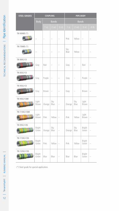
12
RUN
NIN
G M
AN
UA
LTe
naris
Hyd
rilTe
cH
NIc
AL
Rec
oM
MeN
dA
TIo
Ns
Pi
pe Id
entif
icat
ion
–
–
red
purple
brown
orange
pink
orange
pink
blue
–
–
–
–
–
Skyblue
yellow
Skyblue
yellow
blue
–
–
gray
gray
gray
light brown
light brown
bright green
bright green
bright green
pink
Skyblue
gray
gray
gray
orange
pink
orange
pink
blue
yellow
yellow
–
–
–
Skyblue
yellow
Skyblue
yellow
blue
–
–
red
purple
brown
light brown
light brown
bright green
bright green
bright green
TN 60HD (*)
TN 70HD (*)
TN 80Cr13
TN 85Cr13
TN 95Cr13
TN 95Cr13M
TN 110Cr13M
TN 95Cr13S
TN 110Cr13S
TN 125Cr13S
STEEL GRADES
Body
2 nd.1 st. 3 rd.
–
–
–
–
–
–
–
–
–
–
1 st. 2 nd. 3 rd. 4 th.
–
–
–
–
–
–
–
–
–
–
(*) Steel grade for special application.
PIPE BODY
BandsBands
COUPLING

Connection specific Running Guidelines


1
RUN
NIN
G M
AN
UA
LTe
naris
Hyd
rilC
oN
NeC
TIo
N S
peC
IfIC
RU
NN
ING
GU
IdeL
INeS
Tena
risH
ydril
Blu
e® C
onne
ctio
n
IdM
Cod
e G
dL0
0387
/2 /
Mar
ch 2
018
TenarisHydrilBlue® Connection
Scope
These guidelines apply specifically to the use of TenarisHydril Blue® connections. This document should be used in conjunction with the TenarisHydril Running Manual, which is the main document applicable to the running of all TenarisHydril premium connections.
References
.TenarisHydril Running Manual..Premium Connection Approved Thread Compounds, TSH-MD-00.0002..Recommended guidelines for the field inspection of TenarisHydril connections, FSOG 13-005.
Equipment, Material & Documents
1. Verify the appropriate thread compound is available.
2. Refer to document TSH-MD-00.0002 for a list of compounds approved by Tenaris.
3. Latest version of the specific Product Data Sheet can be obtained from Tenaris web site. In case this is unavailable request the data sheet from the local Technical Sales representative or [email protected].

2
RUN
NIN
G M
AN
UA
LTe
naris
Hyd
rilC
oN
NeC
TIo
N S
peC
IfIC
RU
NN
ING
GU
IdeL
INeS
Tena
risH
ydril
Blu
e® C
onne
ctio
n Pre-Running
1. Never move or handle pipe without the correct thread protectors securely in place.
2. Ensure connections are clean and free of all debris and / or contaminants, cleaning methods employed should conform to the recommendations contained within the TenarisHydril Running Manual.
3. Verify all pipe and accessories have genuine TenarisHydril manufactured connections.
4. Visually inspect thread and seal areas prior to running, ensuring no damage is evident.
5. On Dopeless® connections check condition of both pin and box coating ensuring no peel off or degradation has occurred.
6. Verify the compatibility of the Blue® connection with accessories such as cement heads, safety valves, cross overs, etc.
7. Connection weight interchange compatibility is indicated in the TenarisHydril premium connections catalogue.
8. Verify material grade of all accessories ensuring compatibility with main string.

3
RUN
NIN
G M
AN
UA
LTe
naris
Hyd
ril
IDM
Cod
e G
DL0
0387
/2 /
Mar
ch 2
018
Co
NN
eCTI
oN
Spe
CIf
IC R
UN
NIN
G G
UID
eLIN
eS
Te
naris
Hyd
ril B
lue®
Con
nect
ion Blue® Configuration
5 TPI ≤ 5 ½" 4 TPI > 5 ½"
SEAL
DopE pockEt
torquEShouLDEr

4
RUN
NIN
G M
AN
UA
LTe
naris
Hyd
rilC
oN
NeC
TIo
N S
peC
IfIC
RU
NN
ING
GU
IdeL
INeS
Tena
risH
ydril
Blu
e® C
onne
ctio
n Inspection
1. Inspection criteria for all TenarisHydril connections is as outlined in the Field Service Operative Guideline FSOG 13-005.
2. Pay particular attention to seal areas.
3. Ensure the pin nose has no tears, gouges or raised metal.
4. Ensure the pin and box torque shoulders have no dents, tears or raised material which could interfere with correct assembly.
Thread Compound Application
1. Apply a thin coating of thread compound on the pin and box connections, fully covering all threads, seals, pin nose and torque shoulders, the thread form should be fully visible. 2. Use approximately 50% of the quantity applied to the pin when doping the box.
3. Do not fill the dope pocket.
4. For Tenaris approved thread compounds, apply the friction factor indicated in TSH-MD-00.0002. For thread compounds other than those listed, apply the thread compound manufacturers indicated friction factor.

5
RUN
NIN
G M
AN
UA
LTe
naris
Hyd
ril
IDM
Cod
e G
DL0
0387
/2 /
Mar
ch 2
018
Co
NN
eCTI
oN
Spe
CIf
IC R
UN
NIN
G G
UID
eLIN
eS
Te
naris
Hyd
ril B
lue®
Con
nect
ion
Thread Lock Application
Connections must be clean and dry when applying thread lock.
1. Apply a thin coating of thread lock on 50% of the pin threads furthest from the pipe body.
2. Do not apply thread lock on the seal or torque shoulder.
3. Apply thread compound to the box seal and torque shoulder.
4. Do not fill the dope pocket.
5. Apply the thread lock manufacturers indicated friction factor.

6
RUN
NIN
G M
AN
UA
LTe
naris
Hyd
rilC
oN
NeC
TIo
N S
peC
IfIC
RU
NN
ING
GU
IdeL
INeS
Tena
risH
ydril
Blu
e® C
onne
ctio
n Blue® Dopeless®
1. Minor rust or discolouring of the pin connection can be removed with the use of a clean, dry rag ensuring the Dopeless® coating remains intact.
2. Minor rust or discolouring of the box connection can be removed with the use of a non abrasive plastic scouring pad and a clean, dry rag ensuring the Dopeless® coating remains intact.
3. Dopeless® connections do not require the application of thread compound for make up.
4. If for whatever reason thread compound has to be applied to Blue® Dopeless® connections, whether both pin and box are Dopeless® or when mixing a doped connection with Dopeless®, apply thread compound as indicated below.

7
RUN
NIN
G M
AN
UA
LTe
naris
Hyd
ril
IDM
Cod
e G
DL0
0387
/2 /
Mar
ch 2
018
Co
NN
eCTI
oN
Spe
CIf
IC R
UN
NIN
G G
UID
eLIN
eS
Te
naris
Hyd
ril B
lue®
Con
nect
ion NoN DopELESS® piN iNto DopELESS® box
.Apply a thin coating of thread compound on all pin threads, seal and pin nose.
.Apply a thin coat of thread compound to box internal seal and torque shoulder.
.Do not fill the dope pocket with thread compound.
DopELESS® piN iNto StANDArD box
.Apply a very thin coating of thread compound on all pin threads only.
. Do not dope pin seal or box connection.
DopELESS® piN iNto DopELESS® box
. Apply a very thin layer of thread compound on all pin threads only.
.Do not dope pin seal or box connection.
StandardBox
Dopeless®
Box
See page 4
Dope Pin Threads, Seal& Shoulder. Dope Box Seal.
STANDARD PIN
Dope Pin Threads Only
Dope PinThreads Only
DOPELESS® PIN
If applying thread compound to Dopeless® connections use the doped variant torque values.

8
RUN
NIN
G M
AN
UA
LTe
naris
Hyd
rilC
oN
NeC
TIo
N S
peC
IfIC
RU
NN
ING
GU
IdeL
INeS
Tena
risH
ydril
Blu
e® C
onne
ctio
n Blue® Dopeless® Thread Lock
1. Ideally when running a Dopeless® string the connections to be thread locked should be the non Dopeless® variant with the connections cleaned of thread compound and completely dried, then thread lock and dope applied as per page 5.
2. When thread locking Dopeless® connections remove the Dopeless® coating from the threads on the pin connection where the thread lock is to be applied.
3. Leave the Dopeless® coating on the pin seal, torque shoulder and threads where no thread lock is to be applied.
4. Dopeless® boxes should be washed with hot water then dried prior to thread locking.
5. Thread lock should be applied to 50% of the pin threads immediately behind the seal area, as per the diagram on page 5.
6 .When assembling Dopeless® connections with thread lock, apply the non Dopeless® torque values, taken from the standard product data sheet.
7. Apply the thread lock manufacturers indicated friction factor.
8. The application of thread dope is not required.

9
RUN
NIN
G M
AN
UA
LTe
naris
Hyd
ril
IDM
Cod
e G
DL0
0387
/2 /
Mar
ch 2
018
Co
NN
eCTI
oN
Spe
CIf
IC R
UN
NIN
G G
UID
eLIN
eS
Te
naris
Hyd
ril B
lue®
Con
nect
ion Torque Application
1. The use of computer make up analysis equipment is strongly recommended when assembling Blue® connections.
2. Shoulder points for Blue® connections.
.Minimum 15% of optimum.
.Maximum 85% of optimum.
3. Reference torque should initially be set at 5% of optimum.
4. The dump valve should be set at optimum, verify correct operation on the pipe body prior to first make up.
5. Set the computer turns to 2 initially then adjust as necessary to attain good graph depiction.
6. Refer to the TenarisHydril running manual make up acceptance section for further explanation.
7. The computer make up profile for Blue® connections should be similar to the ones below.
TOR
QU
E *
1000
ft-
lbs
MAX. 25800
MAX. SHL 19920
OPT 23440
0
0
6.4
12.8
19.2
25.6
0.34 0.68 1.02 1.36
TURNS
MIN. 21110
MIN. SHL 3520

10
RUN
NIN
G M
AN
UA
LTe
naris
Hyd
rilC
oN
NeC
TIo
N S
peC
IfIC
RU
NN
ING
GU
IdeL
INeS
Tena
risH
ydril
Blu
e® C
onne
ctio
n
8. If different weight or grade of connections are to be mixed apply the lower of the indicated make up torques.
9. When assembling Dopeless® connections the torques applied must be taken from the Dopeless® variant product data sheet.
10. When mixing standard doped and Dopeless® connections apply doped variant torque values.
Running
1. The use of a stabbing guide is strongly recommended.
2. The use of a weight compensator is strongly recommended for chrome, large OD or heavy pipe.
3. To avoid cross threading, stab pipe in a smooth controlled fashion ensuring the pipe is vertical when doing so, continue to support and stabilise the pipe throughout the stabbing and make up operation.
TOR
QU
E *
1000
ft-
lbs
MAX. 18220
0
0
4.4
8.8
13.1
17.5
0.25 0.50 0.74 0.99
TURNS
MIN. 14900
MIN. SHL 2484
OPT 16560
MAX. SHL 14076

11
RUN
NIN
G M
AN
UA
LTe
naris
Hyd
ril
IDM
Cod
e G
DL0
0387
/2 /
Mar
ch 2
018
Co
NN
eCTI
oN
Spe
CIf
IC R
UN
NIN
G G
UID
eLIN
eS
Te
naris
Hyd
ril B
lue®
Con
nect
ion 4. Upon commencement of initial rotation use low
RPM (5 RPM or below) in order to ensure the pipe has not cross threaded during stabbing.
5. If cross threading is evident, immediately reverse rotate the pipe, completely disassemble, clean and inspect both connections.
6. Maximum spin in speed should not exceed 15 RPM. 7. Apply power tong at low RPM (do not exceed 5 RPM) for final make up.
8. Walk chrome pipe all the way in to hand tight, then apply tong only for final make up.
Pulling
1. Automatic stabbing system or stabber is highly recommended to maintain the pipe in a vertical position.
2. The use of a stabbing guide is recommended to assist in centralising the pin to prevent hang up.
3. A weight compensator is strongly recommended for chrome, large OD and heavy pipe.
4. Apply the back up tong jaw on the lower part, over the mill end of the coupling.
5. Apply power tong in low RPM (3-5 RPM) to break the connection, ensuring the pipe is stabilised during the break and spin out process.
6. Do not exceed 15 RPM during spin out.
7. Walk chrome pipe all the way out by hand after initial break.

12
RUN
NIN
G M
AN
UA
LTe
naris
Hyd
rilC
oN
NeC
TIo
N S
peC
IfIC
RU
NN
ING
GU
IdeL
INeS
Tena
risH
ydril
Blu
e® C
onne
ctio
n 8. Visual inspection is recommended to classify the thread condition, any rejected connections should be clearly marked and segregated for further investigation. 9. Apply clean, dry thread protectors after applying storage compound on clean, dry connections.
10. Storage / thread compound should always be applied to connections post job, even rejects.
11. Do not apply storage compound to Dopeless® connections.
12. For long term storage of Dopeless® connections, refurbishment by qualified personnel is recommended.
13. Ensure clean, dry, Dopeless® protectors with seal rings correctly in place are installed.

1
RUN
NIN
G M
AN
UA
LTe
naris
Hyd
rilC
oN
NeC
TIo
N S
peC
IfIC
RU
NN
ING
GU
IdeL
INeS
Tena
risH
ydril
Blu
e® N
ear f
lush
Con
nect
ion
IdM
Cod
e G
dL0
0273
/3 /
Mar
ch 2
018
TenarisHydril Blue® Near Flush ConnectionScope
These guidelines apply specifically to the use of TenarisHydril Blue® Near Flush connections. This document should be used in conjunction with the TenarisHydril Running Manual, which is the main document applicable to the running of all TenarisHydril premium connections.
References
.TenarisHydril Running Manual..Premium Connection Approved Thread Compounds TSH-MD-00.0002..Recommended guidelines for the field inspection of TenarisHydril connections, FSOG 13-005..TenarisHydril Blue® Near Flush Lift Plug TSH-BD-04.0002.
Equipment, Material & Documents
1. Verify the appropriate thread compound is available.
2. Refer to document TSH-MD-00.0002 for a list of compounds approved by Tenaris.
3. Latest version of the specific Product Data Sheet can be obtained from Tenaris website. In case this is unavailable, request the data sheet from the local Technical Sales representative or [email protected].

2
RUN
NIN
G M
AN
UA
LTe
naris
Hyd
rilC
oN
NeC
TIo
N S
peC
IfIC
RU
NN
ING
GU
IdeL
INeS
Tena
risH
ydril
Blu
e® N
ear f
lush
Con
nect
ion Pre-Running
1. Care must be exercised when transporting and handling Blue® Near Flush connections, like any flush or near flush connection they are susceptible to damage if uncontrolled contact with any solid object occurs.
2. Never move or handle pipe without the correct thread protectors securely in place.
3. Ensure connections are cleaned and free of all debris and / or contaminants, cleaning methods employed should conform to the recommendations contained within the TenarisHydril Running Manual.
4. Verify all pipe and accessories have genuine TenarisHydril manufactured connections.
5. Visually inspect threads and seal areas prior to running, ensuring no damage is evident.
6. On Dopeless® connections check condition of both pin and box coating ensuring no peel off or degradation has occurred.
7. Verify the compatibility of the Blue® Near Flush connection with any accessories such as cement heads, safety valves, cross overs, etc.
8. Verify material grade of all accessories ensuring compatibility with main string.
9. Check availability of handling plugs, 3 as a minimum to allow operation flow, ensure they are genuine TenarisHydril manufactured.
10. Check the handling plugs are in good condition and fit correctly onto the pipe.

3
RUN
NIN
G M
AN
UA
LTe
naris
Hyd
ril
IDM
Cod
e G
DL0
0273
/3 /
Mar
ch 2
018
Co
NN
eCTI
oN
Spe
CIf
IC R
UN
NIN
G G
UID
eLIN
eS
Te
naris
Hyd
ril B
lue®
Nea
r flu
sh C
onne
ctio
n 11. Check single joint elevators have sufficient clearance to slide over the box expanded area and seat against the handling plug.
12. Never exceed the maximum lift capacity of the handling plug, stamped on the plug flange.
13. Refer to the TenarisHydril running manual for the care and use of handling / lift plugs.
14. Blue® Near Flush connections are a weight specific design therefore connections and handling plugs are not interchangeable between different weights of the same OD.
Inspection
1. Inspection criteria for all TenarisHydril connections is as outlined in the Field Service Operative Guideline FSOG 13-005.
2. Pay particular attention to seal areas.
3. Ensure the pin nose has no tears, gouges or raised metal.
4. Ensure the pin and box torque shoulders have no dents, tears or raised material which would interfere with correct assembly.
5. Check for mashes or ovality which may have occurred during transportation or storage.

4
RUN
NIN
G M
AN
UA
LTe
naris
Hyd
rilC
oN
NeC
TIo
N S
peC
IfIC
RU
NN
ING
GU
IdeL
INeS
Tena
risH
ydril
Blu
e® N
ear f
lush
Con
nect
ion Blue® Near Flush Configuration
Hooked THread
5 TPI ≤ 7" 26 lb.ft4 TPI ≥ 7" 29 lb.ft

5
RUN
NIN
G M
AN
UA
LTe
naris
Hyd
ril
IDM
Cod
e G
DL0
0273
/3 /
Mar
ch 2
018
Co
NN
eCTI
oN
Spe
CIf
IC R
UN
NIN
G G
UID
eLIN
eS
Te
naris
Hyd
ril B
lue®
Nea
r flu
sh C
onne
ctio
n
exTernal Seal
Torque SHoulder
dope pockeT
InTernal Seal

6
RUN
NIN
G M
AN
UA
LTe
naris
Hyd
rilC
oN
NeC
TIo
N S
peC
IfIC
RU
NN
ING
GU
IdeL
INeS
Tena
risH
ydril
Blu
e® N
ear f
lush
Con
nect
ion Thread Compound Application
1. Apply a thin coating of thread compound on the pin connection, fully covering all threads, seals, pin nose and torque shoulder, the thread form should be fully visible.
2. Apply a thin coating of thread compound on the box seals.
3. Do not fill the box dope pocket.
4. For Tenaris approved thread compounds, apply the friction factor indicated in TSH-MD-00.0002. For thread compounds other than those listed, apply the thread compound manufacturers indicated friction factor.

7
RUN
NIN
G M
AN
UA
LTe
naris
Hyd
ril
IDM
Cod
e G
DL0
0273
/3 /
Mar
ch 2
018
Co
NN
eCTI
oN
Spe
CIf
IC R
UN
NIN
G G
UID
eLIN
eS
Te
naris
Hyd
ril B
lue®
Nea
r flu
sh C
onne
ctio
n Thread Lock Application
Connections must be clean and dry when applying thread lock
1. Apply a thin coating of thread lock to the first 50% of each thread section.
2. Do not apply thread lock on the seals or torque shoulder.
3. Apply thread compound to the pin external seal.
4. Apply thread compound to the box internal seal and torque shoulder.
5. Do not fill the dope pocket.
6. Apply the thread lock manufacturers indicated friction factor.

8
RUN
NIN
G M
AN
UA
LTe
naris
Hyd
rilC
oN
NeC
TIo
N S
peC
IfIC
RU
NN
ING
GU
IdeL
INeS
Tena
risH
ydril
Blu
e® N
ear f
lush
Con
nect
ion Blue® Near Flush Dopeless®
1. Minor rust or discolouring of the pin connection can be removed with the use of a clean, dry rag ensuring the Dopeless® coating remains intact.
2. Minor rust or discolouring of the box connection can be removed with the use of a non abrasive plastic scouring pad and a clean, dry rag ensuring the Dopeless® coating remains intact.
3. Dopeless® connections do not require the application of thread compound for make up.
4. If for whatever reason thread compound has to be applied to Blue® Near Flush Dopeless® connections, whether both pin and box are Dopeless® or when mixing a doped connection with a Dopeless®, apply thread compound as indicated below.

9
RUN
NIN
G M
AN
UA
LTe
naris
Hyd
ril
IDM
Cod
e G
DL0
0273
/3 /
Mar
ch 2
018
Co
NN
eCTI
oN
Spe
CIf
IC R
UN
NIN
G G
UID
eLIN
eS
Te
naris
Hyd
ril B
lue®
Nea
r flu
sh C
onne
ctio
n non dopeleSS® pIn InTo dopeleSS® box
.Apply a thin coating of thread compound on all pin threads, seals and torque shoulder.
.Apply a thin coat of thread compound to box internal seals and torque shoulder.
. Do not fill the dope pocket with thread compound.
dopeleSS® pIn InTo STandard box
. Apply a very thin coating of thread compound on all pin threads only.
. Do not dope pin seals or box connection.
dopeleSS® pIn InTo dopeleSS® box
. Apply a very thin layer of thread compound on all pin threads only.
. Do not dope pin seals or box connection.
StandardBox
Dopeless®
Box
See page 6
Dope Pin Threads, Seals& Shoulder. Dope Box Seals.
STANDARD PIN
Dope Pin Threads Only
Dope PinThreads Only
DOPELESS® PIN
If applying thread compound to Dopeless® connections use the doped variant torque values.

10
RUN
NIN
G M
AN
UA
LTe
naris
Hyd
rilC
oN
NeC
TIo
N S
peC
IfIC
RU
NN
ING
GU
IdeL
INeS
Tena
risH
ydril
Blu
e® N
ear f
lush
Con
nect
ion Blue® Near Flush Dopeless®
Thread Lock
1. Ideally when running a Dopeless® string the connections to be thread locked should be the non Dopeless® variant with the connections cleaned of thread compound and completely dried, then thread lock and dope applied as per page 7.
2. When thread locking Dopeless® connections remove the Dopeless® coating from the threads on the pin connection where the thread lock is to be applied.
3. Leave the Dopeless® coating on the pin seals, torque shoulder and threads where no thread lock is to be applied.
4. Dopeless® boxes should be washed with hot water then dried prior to thread locking.
5. Thread lock should be applied to 50% of the pin threads of each thread section, as per the diagram on page 7.
6. The application of thread dope is not required.
7. When assembling Dopeless® connections with thread lock, apply the non Dopeless® torque values, taken from the standard product data sheet.
8. Apply the thread lock manufacturers indicated friction factor.

11
RUN
NIN
G M
AN
UA
LTe
naris
Hyd
ril
IDM
Cod
e G
DL0
0273
/3 /
Mar
ch 2
018
Co
NN
eCTI
oN
Spe
CIf
IC R
UN
NIN
G G
UID
eLIN
eS
Te
naris
Hyd
ril B
lue®
Nea
r flu
sh C
onne
ctio
n Torque Application
1. The use of computer make up analysis equipment is strongly recommended when assembling Blue® Near Flush connections.
2. Shoulder points for Blue® Near Flush connections.
.Minimum 10% of optimum.
.Maximum 85% of optimum.
.A shoulder point above 85% can be accepted but should never exceed 90% of optimum torque, additionally the graph must also display a minimum delta torque of 5% of optimum.
.Delta torque % = (final torque – shoulder torque) x 100 ÷ optimum torque.
3. Reference torque should initially be set at 5% of optimum torque.
4. The dump valve should be set at optimum, verify correct operation on the pipe body prior to first make up.
5. Set the computer turns to 2 initially then adjust as necessary to attain good graph depiction.
6. Refer to the TenarisHydril Running Manual make up acceptance section for further explanation.
7. Blue® Near Flush connections of the same diameter are not interchangeable with different weights.
8. If different grades of the same diameter and weight are to be mixed use the lower of the two torques.
9. When assembling Dopeless® connections the torques applied must be taken from the Dopeless® variant product data sheet.

12
RUN
NIN
G M
AN
UA
LTe
naris
Hyd
rilC
oN
NeC
TIo
N S
peC
IfIC
RU
NN
ING
GU
IdeL
INeS
Tena
risH
ydril
Blu
e® N
ear f
lush
Con
nect
ion 10. When mixing standard doped and Dopeless®
connections apply the doped variant torque values.
11. The computer make up profile for Blue® Near Flush connections should be similar to the ones below.
TOR
QU
E *
1000
ft-
lbs
MAX. 18220
0
0
4.4
8.8
13.1
17.5
0.25 0.50 0.74 0.99
TURNS
MIN. 14900
MIN. SHL 1656
OPT 16560
MAX. SHL 14076
TOR
QU
E *
1000
ft-
lbs
MAX. 6710
MAX. SHL 5185OPT 6100
0
0
1.7
3.4
5.0
6.7
0.23 0.45 0.68 0.91
TURNS
MIN. 5490
MIN. SHL 610
Running 1. The use of a stabbing guide is strongly recommended.
2. Slip type elevators are recommended.

13
RUN
NIN
G M
AN
UA
LTe
naris
Hyd
ril
IDM
Cod
e G
DL0
0273
/3 /
Mar
ch 2
018
Co
NN
eCTI
oN
Spe
CIf
IC R
UN
NIN
G G
UID
eLIN
eS
Te
naris
Hyd
ril B
lue®
Nea
r flu
sh C
onne
ctio
n 3. The use of a safety clamp is strongly recommended when running Blue® Near flush connections.
4. The use of a weight compensator is strongly recommended for chrome, large OD and heavy pipe.
5. To avoid cross threading stab pipe in a smooth controlled fashion ensuring the pipe is vertical when doing so, continue to support and stabilise the pipe throughout the stabbing and make up operation.
6. Ensure the back up tong is located below the box upset to prevent damage.
7. Upon commencement of initial rotation use low RPM (5 RPM or below) in order to ensure the pipe has not cross threaded during stabbing.
8. If cross threading is evident, immediately reverse rotate the pipe, completely disassemble, clean and inspect both connections.
9. Maximum spin in speed should not exceed 15 RPM.
10. Apply power at low RPM (do not exceed 5 RPM) for final make up.
11. Walk chrome pipe all the way in to hand tight, then apply tong only for final make up.
Pulling
1. Automatic stabbing system or stabber is highly recommended to stabilise the pipe vertically.
2. The use of a stabbing guide is recommended to assist in centralizing the pin to prevent hang up.

14
RUN
NIN
G M
AN
UA
LTe
naris
Hyd
rilC
oN
NeC
TIo
N S
peC
IfIC
RU
NN
ING
GU
IdeL
INeS
Tena
risH
ydril
Blu
e® N
ear f
lush
Con
nect
ion 3. The use of a safety clamp is strongly recommended.
4. A weight compensator is strongly recommended for chrome, large OD and heavy weight pipe.
5. Apply the back up tong on the pipe body below the expanded area.
6. Apply power tong in low RPM (3-5 RPM) to break the connection, ensuring the pipe is stabilised during the break and spin out process.
7. Do not exceed 15 RPM during spin out.
8. Walk chrome pipe all the way out by hand after initial break.
9. Visual inspection is recommended to classify the thread condition, any rejected connections should be clearly marked and segregated for further investigation.
10. Apply clean, dry thread protectors after applying storage compound on clean, dry connections.
11. Storage / thread compound should always be applied to connections post job, even rejects.
12. Do not apply storage compound to Dopeless® connections.
13. For long term storage of Dopeless® connections, refurbishment by qualified personnel is recommended.
14. Ensure clean, dry, Dopeless® protectors with seal rings correctly in place are installed.

1
RUN
NIN
G M
AN
UA
LTe
naris
Hyd
rilC
oN
NeC
TIo
N S
peC
IfIC
RU
NN
ING
GU
IdeL
INeS
Tena
risH
ydril
Blu
e® T
herm
al L
iner
Con
nect
ion
IdM
Cod
e G
dL2
3367
/1 /
Mar
ch 2
018
TenarisHydril Blue® Thermal Liner ConnectionScope
These guidelines apply specifically to the use of TenarisHydril Blue® Thermal Liner connections. This document should be used in conjunction with the TenarisHydril Running Manual, which is the main document applicable to the running of all TenarisHydril Premium Connections.
References
.TenarisHydril Running Manual..Premium Connection Approved Thread Compounds TSH-MD-00.0002..Recommended guidelines for the field inspection of TenarisHydril connections, FSOG 13-005.
Equipment, Material & Documents
1. Verify the appropriate thread compound is available.
2. Refer to document TSH-MD-00.0002 for a list of compounds approved by Tenaris.
3. Latest version of the specific Product Data Sheet can be obtained from the Tenaris web site. In case this is unavailable, request the data sheet from the local Technical Sales representative or [email protected].

2
RUN
NIN
G M
AN
UA
LTe
naris
Hyd
rilC
oN
NeC
TIo
N S
peC
IfIC
RU
NN
ING
GU
IdeL
INeS
Tena
risH
ydril
Blu
e® T
herm
al L
iner
Con
nect
ion Pre-Running
1. Never move or handle pipe without the correct thread protectors securely in place.
2. Ensure connections are cleaned and free of all debris and / or contaminants, cleaning methods employed should conform to the recommendations contained within the TenarisHydril Running Manual.
3. Verify all pipe and accessories have genuine TenarisHydril manufactured connections.
4. Visually inspect threads and torque shoulder prior to running, ensuring no damage is evident.
5. On Dopeless® connections check condition of both pin and box coating ensuring no peel off or degradation has occurred.
6. Verify the compatibility of the Blue® Thermal Liner pipe with any accessories such as cement heads, safety valves, cross overs, etc.
7. Connection weight interchange capability is indicated in the TenarisHydril premium connections catalogue.
8. Verify material grade of all accessories ensuring compatibility with the main string.
Inspection
1. Inspection criteria for all TenarisHydril connections is as outlined in the Field Service Operative Guideline FSOG 13-005.
2. Ensure the pin and box torque shoulders have no dents, tears or raised material which would interfere with correct assembly.

3
RUN
NIN
G M
AN
UA
LTe
naris
Hyd
ril
IDM
Cod
e G
DL2
3367
/1 /
Mar
ch 2
018
Co
NN
eCTI
oN
Spe
CIf
IC R
UN
NIN
G G
UID
eLIN
eS
Te
naris
Hyd
ril B
lue®
The
rmal
Lin
er C
onne
ctio
nBlue® Thermal Liner Configuration
5 TPI ≤ 5 ½"4 TPI > 5 ½"No Metal to Metal seal
torque shoulder

4
RUN
NIN
G M
AN
UA
LTe
naris
Hyd
rilC
oN
NeC
TIo
N S
peC
IfIC
RU
NN
ING
GU
IdeL
INeS
Tena
risH
ydril
Blu
e® T
herm
al L
iner
Con
nect
ion Thread Compound Application
1. Apply a thin coating of thread compound on the pin and box connections, fully covering all threads, pin nose and torque shoulders, the thread form should be fully visible.
2. Use approximately 50% of the quantity applied to the pin when doping the box.
3. For Tenaris approved thread compounds, apply the friction factor indicated in TSH-MD-00.0002. For thread compounds other than those listed, apply the thread compound manufacturers indicated friction factor.
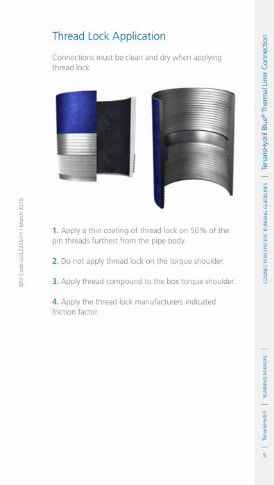
5
RUN
NIN
G M
AN
UA
LTe
naris
Hyd
ril
IDM
Cod
e G
DL2
3367
/1 /
Mar
ch 2
018
Co
NN
eCTI
oN
Spe
CIf
IC R
UN
NIN
G G
UID
eLIN
eS
Te
naris
Hyd
ril B
lue®
The
rmal
Lin
er C
onne
ctio
nThread Lock Application
Connections must be clean and dry when applying thread lock
1. Apply a thin coating of thread lock on 50% of the pin threads furthest from the pipe body.
2. Do not apply thread lock on the torque shoulder.
3. Apply thread compound to the box torque shoulder.
4. Apply the thread lock manufacturers indicated friction factor.

6
RUN
NIN
G M
AN
UA
LTe
naris
Hyd
rilC
oN
NeC
TIo
N S
peC
IfIC
RU
NN
ING
GU
IdeL
INeS
Tena
risH
ydril
Blu
e® T
herm
al L
iner
Con
nect
ion Blue® Thermal Liner Dopeless®
1. Minor rust or discolouring of the pin connection can be removed with the use of a clean, dry rag ensuring the Dopeless® coating remains intact.
2. Minor rust or discolouring of the box connection can be removed with the use of a non abrasive plastic scouring pad and a clean, dry rag ensuring the Dopeless® coating remains intact.
3. Dopeless® connections do not require the application of thread compound for make up.
4. If for whatever reason thread compound has to be applied to Blue® Thermal Liner Dopeless® connections, whether both pin and box are Dopeless® or when mixing a doped connection with Dopeless®, apply thread compound as indicated below.

7
RUN
NIN
G M
AN
UA
LTe
naris
Hyd
ril
IDM
Cod
e G
DL2
3367
/1 /
Mar
ch 2
018
Co
NN
eCTI
oN
Spe
CIf
IC R
UN
NIN
G G
UID
eLIN
eS
Te
naris
Hyd
ril B
lue®
The
rmal
Lin
er C
onne
ctio
nNoN dopeless® piN iNto dopeless® box
. Apply a thin coating of thread compound on all pin threads and pin nose.
. Apply a thin coat of thread compound to box torque shoulder.
dopeless® piN iNto staNdard box
. Apply a very thin coating of thread compound on all pin threads only.
. Do not dope box connection.
dopeless® piN iNto dopeless® box
. Apply a very thin layer of thread compound on all pin threads only.
. Do not dope box connection.
If applying thread compound to Dopeless® connections use the doped variant torque values.
StandardBox
Dopeless®
Box
See page 4
Dope Pin Threads & Shoulder. Dope Box Shoulder
STANDARD PIN
Dope Pin Threads Only
Dope PinThreads Only
DOPELESS® PIN

8
RUN
NIN
G M
AN
UA
LTe
naris
Hyd
rilC
oN
NeC
TIo
N S
peC
IfIC
RU
NN
ING
GU
IdeL
INeS
Tena
risH
ydril
Blu
e® T
herm
al L
iner
Con
nect
ion Thread Lock Blue®
Thermal Liner Dopeless®
1. Ideally when running a Dopeless® string the connections to be thread locked should be the non Dopeless® option with the connections cleaned of thread compound and completely dried, then thread lock and dope applied as per page 5.
2. When thread locking Dopeless® connections remove the Dopeless® coating from the threads on the pin connection where the thread lock is to be applied.
3. Leave the Dopeless® coating on the pin nose, torque shoulder and threads where no thread lock is to be applied.
4. Dopeless® boxes should be washed with hot water then dried prior to thread locking.
5. Thread lock should be applied to 50% of the pin threads immediately behind the pin nose, as per the diagram in page 5.
6. When assembling Dopeless® connections with thread lock, apply the non Dopeless® torque values taken from the standard product data sheet.
7. Apply the thread lock manufacturers indicated friction factor.
8. The application of thread dope is not required.

9
RUN
NIN
G M
AN
UA
LTe
naris
Hyd
ril
IDM
Cod
e G
DL2
3367
/1 /
Mar
ch 2
018
Co
NN
eCTI
oN
Spe
CIf
IC R
UN
NIN
G G
UID
eLIN
eS
Te
naris
Hyd
ril B
lue®
The
rmal
Lin
er C
onne
ctio
nTorque Application
1. The use of computer make up analysis equipment is strongly recommended when assembling Blue® Thermal Liner connections.
2. Shoulder points for Blue® Thermal Liner.
.Minimum 15% of optimum torque.
.Maximum 85% of optimum torque.
3. Reference torque should initially be set at 5% of optimum torque.
4. The dump valve should be set at optimum torque, verify correct operation on the pipe body prior to first make up.
5. Set the computer turns to 2 initially then adjust as necessary to attain good graph depiction.
6. Refer to the TenarisHydril running manual make up acceptance section for further explanation.
7. The computer make up profile for Blue® Thermal Liner should be similar to the ones below.
TOP SHD
TURNS
MAX. SHL 13860MIN. 14680
OPT 16310
MAX. 17940
MIN. SHL 2450
TOR
QU
E

10
RUN
NIN
G M
AN
UA
LTe
naris
Hyd
rilC
oN
NeC
TIo
N S
peC
IfIC
RU
NN
ING
GU
IdeL
INeS
Tena
risH
ydril
Blu
e® T
herm
al L
iner
Con
nect
ion
8. If different weight or grade of connections are to be mixed apply the lower of the indicated make up torques.
9. When assembling Dopeless® connections the torques applied must be taken from the Dopeless® variant product data sheet.
10. When mixing standard doped and Dopeless® connections apply doped variant torque values.
Running 1. The use of a stabbing guide is strongly recommended.
2. The use of a weight compensator is strongly recommended for chrome, large OD and heavy pipe.
3. To avoid cross threading stab pipe in a smooth controlled fashion ensuring the pipe is vertical when doing so, continue to support and stabilise the pipe throughout the stabbing and make up operation.
TOP SHD
TURNS
MAX. SHL 13860MIN. 14680
OPT 16310
MAX. 17940
MIN. SHL 2450
TOR
QU
E
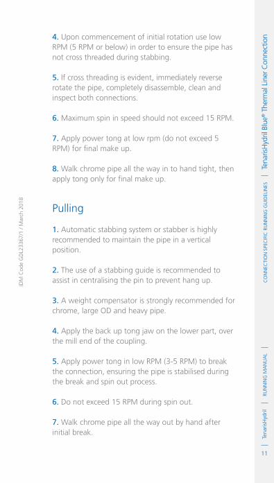
11
RUN
NIN
G M
AN
UA
LTe
naris
Hyd
ril
IDM
Cod
e G
DL2
3367
/1 /
Mar
ch 2
018
Co
NN
eCTI
oN
Spe
CIf
IC R
UN
NIN
G G
UID
eLIN
eS
Te
naris
Hyd
ril B
lue®
The
rmal
Lin
er C
onne
ctio
n4. Upon commencement of initial rotation use low RPM (5 RPM or below) in order to ensure the pipe has not cross threaded during stabbing.
5. If cross threading is evident, immediately reverse rotate the pipe, completely disassemble, clean and inspect both connections.
6. Maximum spin in speed should not exceed 15 RPM.
7. Apply power tong at low rpm (do not exceed 5 RPM) for final make up.
8. Walk chrome pipe all the way in to hand tight, then apply tong only for final make up.
Pulling
1. Automatic stabbing system or stabber is highly recommended to maintain the pipe in a vertical position.
2. The use of a stabbing guide is recommended to assist in centralising the pin to prevent hang up.
3. A weight compensator is strongly recommended for chrome, large OD and heavy pipe.
4. Apply the back up tong jaw on the lower part, over the mill end of the coupling.
5. Apply power tong in low RPM (3-5 RPM) to break the connection, ensuring the pipe is stabilised during the break and spin out process.
6. Do not exceed 15 RPM during spin out.
7. Walk chrome pipe all the way out by hand after initial break.

12
RUN
NIN
G M
AN
UA
LTe
naris
Hyd
rilC
oN
NeC
TIo
N S
peC
IfIC
RU
NN
ING
GU
IdeL
INeS
Tena
risH
ydril
Blu
e® T
herm
al L
iner
Con
nect
ion 8. Visual inspection is recommended to classify the
thread condition. Any rejected connections should be clearly marked and segregated for further investigation.
9. Apply clean, dry thread protectors after applying storage compound on clean, dry connections.
10. Storage / thread compound should always be applied to connections post job, even rejects.
11. Do not apply storage compound to Dopeless® connections.
12. For long term storage of Dopeless® connections, refurbishment by qualified personnel is recommended.
13. Ensure clean, dry, Dopeless® protectors with seal rings correctly in place are installed.

1
RUN
NIN
G M
AN
UA
LTe
naris
Hyd
rilC
oN
NeC
TIo
N S
peC
IfIC
RU
NN
ING
GU
IdeL
INeS
Tena
risH
ydril
Blu
e® H
eavy
Wal
l Con
nect
ion
IdM
Cod
e G
dL0
0372
/3 /
Mar
ch 2
018
TenarisHydrilBlue® Heavy WallConnectionScope
These guidelines apply specifically to the use of TenarisHydril Blue® Heavy Wall connections. This document should be used in conjunction with the TenarisHydril Running Manual, which is the main document applicable to the running of all TenarisHydril premium connections.
References
.TenarisHydril Running Manual..Premium Connection Approved Thread Compounds TSH-MD-00.0002..Recommended guidelines for the field inspection of TenarisHydril connections, FSOG 13-005.
Equipment, Material & Documents
1. Verify the appropriate thread compound is available.
2. Refer to document TSH-MD-00.0002 for a list of compounds approved by Tenaris.
3. Latest version of the specific Product Data Sheet can be obtained from Tenaris web site. In case this is unavailable, request the data sheet from the local Technical Sales representative or [email protected].
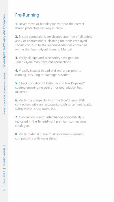
2
RUN
NIN
G M
AN
UA
LTe
naris
Hyd
rilC
oN
NeC
TIo
N S
peC
IfIC
RU
NN
ING
GU
IdeL
INeS
Tena
risH
ydril
Blu
e® H
eavy
Wal
l Con
nect
ion Pre-Running
1. Never move or handle pipe without the correct thread protectors securely in place.
2. Ensure connections are cleaned and free of all debris and / or contaminants, cleaning methods employed should conform to the recommendations contained within the TenarisHydril Running Manual.
3. Verify all pipe and accessories have genuine TenarisHydril manufactured connections.
4. Visually inspect thread and seal areas prior to running, ensuring no damage is evident.
5. Check condition of both pin and box Dopeless® coating ensuring no peel off or degradation has occurred.
6. Verify the compatibility of the Blue® Heavy Wall connection with any accessories such as cement heads, safety valves, cross overs, etc.
7. Connection weight interchange compatibility is indicated in the TenarisHydril premium connections catalogue.
8. Verify material grade of all accessories ensuring compatibility with main string.

3
RUN
NIN
G M
AN
UA
LTe
naris
Hyd
ril
IDM
Cod
e G
DL0
0372
/3 /
Mar
ch 2
018
Co
NN
eCTI
oN
Spe
CIf
IC R
UN
NIN
G G
UID
eLIN
eS
Te
naris
Hyd
ril B
lue®
Hea
vy W
all C
onne
ctio
n Inspection
1. Inspection criteria for all TenarisHydril connections is as outlined in the Field Service Operative Guideline FSOG 13-005.
2. Pay particular attention to seal areas.
3. Ensure there is no raised metal on the external seal lead in area directly behind the last pin thread.
4. Ensure the pin and box torque shoulders have no dents, tears or raised material which could interfere with correct assembly.

4
RUN
NIN
G M
AN
UA
LTe
naris
Hyd
rilC
oN
NeC
TIo
N S
peC
IfIC
RU
NN
ING
GU
IdeL
INeS
Tena
risH
ydril
Blu
e® H
eavy
Wal
l Con
nect
ion Blue® Heavy Wall Configuration
Single or twin start threads, dependent on connection weight, are not interchangeable.
Always check compatibility and visually inspect threads prior to mixing weights.

5
RUN
NIN
G M
AN
UA
LTe
naris
Hyd
ril
IDM
Cod
e G
DL0
0372
/3 /
Mar
ch 2
018
Co
NN
eCTI
oN
Spe
CIf
IC R
UN
NIN
G G
UID
eLIN
eS
Te
naris
Hyd
ril B
lue®
Hea
vy W
all C
onne
ctio
n
ExtErnal SEal
3 or 4 tPI
HookEd tHrEad
lEad In arEa
IntErnal SEal
torquE SHouldEr

6
RUN
NIN
G M
AN
UA
LTe
naris
Hyd
rilC
oN
NeC
TIo
N S
peC
IfIC
RU
NN
ING
GU
IdeL
INeS
Tena
risH
ydril
Blu
e® H
eavy
Wal
l Con
nect
ion Blue® Heavy Wall Dopeless®
1. Minor rust or discolouring of the pin connection can be removed with the use of a clean, dry rag ensuring the Dopeless® coating remains intact.
2. Minor rust or discolouring of the box connection can be removed with the use of a non abrasive plastic scouring pad and a clean, dry rag ensuring the Dopeless® coating remains intact.
3. Dopeless® connections do not require the application of thread compound for make up.

7
RUN
NIN
G M
AN
UA
LTe
naris
Hyd
ril
IDM
Cod
e G
DL0
0372
/3 /
Mar
ch 2
018
Co
NN
eCTI
oN
Spe
CIf
IC R
UN
NIN
G G
UID
eLIN
eS
Te
naris
Hyd
ril B
lue®
Hea
vy W
all C
onne
ctio
n If for whatever reason thread compound has to be applied to Blue® Heavy Wall Dopeless® connections, whether both pin and box are Dopeless® or when mixing a doped connection with a Dopeless®, apply thread compound as indicated below.
non doPElESS® PIn Into doPElESS® box
.Apply a thin coating of thread compound on all pin threads, seals and pin nose.
.Apply a thin coat of thread compound to box internal & external seals and torque shoulder.
.Do not fill the dope pockets with thread compound.
doPElESS® PIn Into Standard box
.Apply a very thin coating of thread compound on all pin threads only.
. Do not dope pin seals or box connection.
doPElESS® PIn Into doPElESS® box
.Apply a very thin layer of thread compound on all pin threads only.
.Do not dope pin seals or box connection.
StandardBox
Dopeless®
Box
See page 9
Dope Pin Threads, Seals& Shoulder. Dope Box Seals.
STANDARD PIN
Dope Pin Threads Only
Dope PinThreads Only
DOPELESS® PIN
If applying thread compound to Dopeless® connections use doped variant torque values.Contact Tenaris for torque values.

8
RUN
NIN
G M
AN
UA
LTe
naris
Hyd
rilC
oN
NeC
TIo
N S
peC
IfIC
RU
NN
ING
GU
IdeL
INeS
Tena
risH
ydril
Blu
e® H
eavy
Wal
l Con
nect
ion Blue® Heavy Wall Dopeless®
Thread Lock
1. Ideally when running a Dopeless® string the connections to be thread locked should be the non Dopeless® variant with the connections cleaned of thread compound and completely dried, then thread lock and dope applied as per page 10.
2. When thread locking Dopeless® connections remove the Dopeless® coating from the threads of the pin connection where the thread lock is to be applied.
3. Leave the Dopeless® coating on the pin seals, torque shoulder and threads where no thread lock is to be applied.
4. Dopeless® boxes should be washed with hot water then dried prior to thread locking.
5. Thread lock should be applied to 50% of the pin threads immediately behind the pin nose seal area, as per the diagram in page 10.
6. When assembling Dopeless® connections with thread lock, apply the non Dopeless® torque values taken from the standard product data sheet.
7. Apply the thread lock manufacturers indicated friction factor.
8. The application of thread dope is not required.
9. Contact Tenaris for further information on the thread locking process.

9
RUN
NIN
G M
AN
UA
LTe
naris
Hyd
ril
IDM
Cod
e G
DL0
0372
/3 /
Mar
ch 2
018
Co
NN
eCTI
oN
Spe
CIf
IC R
UN
NIN
G G
UID
eLIN
eS
Te
naris
Hyd
ril B
lue®
Hea
vy W
all C
onne
ctio
n
1. Apply a thin coating of thread compound on the pin connection, fully covering all threads, seals, pin nose and torque shoulder, the thread form should be fully visible.
2. Apply a thin coating of thread compound on the box internal seal and torque shoulder, do not fill the dope pocket.
3. Apply a thin coating of thread compound on the box external seal and lead in area, do not pack the dope pocket.
4. For Tenaris approved thread compounds, apply the friction factor indicated in TSH-MD-00.0002. For thread compounds other than those listed, apply the thread compound manufacturers indicated friction factor.
Thread Compound Application
If two non Dopeless® connections are to be assembled apply thread compound as indicated below.

10
RUN
NIN
G M
AN
UA
LTe
naris
Hyd
rilC
oN
NeC
TIo
N S
peC
IfIC
RU
NN
ING
GU
IdeL
INeS
Tena
risH
ydril
Blu
e® H
eavy
Wal
l Con
nect
ion Thread Lock Application
For non Dopeless® connections apply thread lock as indicated below.
Connections must be clean and dry when applying thread lock.
1. Apply a thin coating of thread lock on 50% of the pin threads furthest from the pipe body.
2. Apply thread compound on the pin external seal and lead in area after the last thread.
3. Do not apply thread lock on the internal seal or torque shoulder.
4. Apply thread compound to the box internal seal and torque shoulder, do not fill the dope pocket.
5. Apply the thread lock manufacturers indicated friction factor.

11
RUN
NIN
G M
AN
UA
LTe
naris
Hyd
ril
IDM
Cod
e G
DL0
0372
/3 /
Mar
ch 2
018
Co
NN
eCTI
oN
Spe
CIf
IC R
UN
NIN
G G
UID
eLIN
eS
Te
naris
Hyd
ril B
lue®
Hea
vy W
all C
onne
ctio
n
Torque Application
1. The use of computer make up analysis equipment is strongly recommended when assembling Blue® Heavy Wall connections.
2. Shoulder points for Blue® Heavy Wall connections.
.Minimum 15% of optimum.
.Maximum 85% of optimum.
3. Reference torque should initially be set at 5% of optimum torque.
4. The dump valve should be set at optimum torque, verify correct operation on the pipe body prior to first make up.
5. Set the computer turns to 2 initially then adjust as necessary to attain good graph depiction.
6. Refer to the TenarisHydril Running Manual, make up acceptance section for further explanation.
7. The computer graph make up profile for Blue® Heavy Wall connections should be similar to the ones below.
TOP SHD
TOR
QU
E
1.356
0
10000
20000
30000
40000
50000
60302
5.356TURNS
MAX 54820
MIN SHL 7476
MAX SHL 42364
MIN 44860OPT 49840

12
RUN
NIN
G M
AN
UA
LTe
naris
Hyd
rilC
oN
NeC
TIo
N S
peC
IfIC
RU
NN
ING
GU
IdeL
INeS
Tena
risH
ydril
Blu
e® H
eavy
Wal
l Con
nect
ion
8. Blue® Heavy Wall connections have limited same size / weight interchange capability, if mixing weight / grade ensure compatibility of design and apply the lower torque values of the two connections.
9. Blue® Heavy Wall connections of the same size may have one or two thread starts depending on wall thickness; close inspection of dissimilar weight connections is essential, the different thread start types cannot be mixed.
10. When assembling Dopeless® connections the torques applied must be taken from the Dopeless® variant product data sheet.
11. When mixing standard doped and Dopeless® connections apply doped variant torque values.
12. Contact Tenaris for torque values.
TOP SHD
TOR
QU
E
0.088
0
10000
20000
30000
40000
50000
60302
4.088TURNS
MAX 54820
MIN SHL 7476
MAX SHL 42364
MIN 44860OPT 49840

13
RUN
NIN
G M
AN
UA
LTe
naris
Hyd
ril
IDM
Cod
e G
DL0
0372
/3 /
Mar
ch 2
018
Co
NN
eCTI
oN
Spe
CIf
IC R
UN
NIN
G G
UID
eLIN
eS
Te
naris
Hyd
ril B
lue®
Hea
vy W
all C
onne
ctio
n
Running 1. The use of a stabbing guide is strongly recommended.
2. The use of a weight compensator is strongly recommended for chrome, large OD and heavy pipe.
3. To avoid cross threading stab pipe in a smooth controlled fashion ensuring the pipe is vertical when doing so, continue to support and stabilise the pipe throughout the stabbing and make up operation.
4. Twin thread start connections can have as little as 2 ½ turns from stabbing to make up.
5. Twin Start Threads: Rotate at 5 RPM or below to final make up torque.
6. Single Start Threads: Commence rotation slowly to ensure no cross threading then spin in at 10 RPM or lower, final make up should be made below 5 RPM.
7. If cross threading is evident, immediately reverse rotate the pipe, completely disassemble, clean and inspect both connections.
8. Walk chrome pipe all the way in to hand tight, then apply tong only for final make up.
Pulling
1. Automatic stabbing system or stabber is highly recommended to maintain the pipe in a vertical position.
2. The use of a stabbing guide is recommended to assist in centralising the pin to prevent hang up.
3. A weight compensator is strongly recommended for chrome, large OD and heavy pipe.
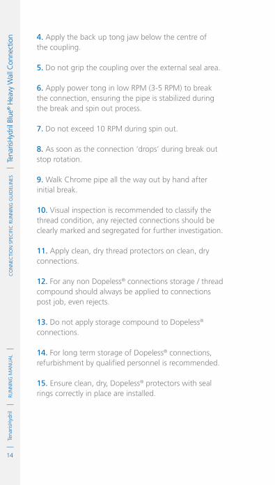
14
RUN
NIN
G M
AN
UA
LTe
naris
Hyd
rilC
oN
NeC
TIo
N S
peC
IfIC
RU
NN
ING
GU
IdeL
INeS
Tena
risH
ydril
Blu
e® H
eavy
Wal
l Con
nect
ion 4. Apply the back up tong jaw below the centre of
the coupling.
5. Do not grip the coupling over the external seal area.
6. Apply power tong in low RPM (3-5 RPM) to break the connection, ensuring the pipe is stabilized during the break and spin out process.
7. Do not exceed 10 RPM during spin out.
8. As soon as the connection ‘drops’ during break out stop rotation.
9. Walk Chrome pipe all the way out by hand after initial break.
10. Visual inspection is recommended to classify the thread condition, any rejected connections should be clearly marked and segregated for further investigation.
11. Apply clean, dry thread protectors on clean, dry connections.
12. For any non Dopeless® connections storage / thread compound should always be applied to connections post job, even rejects.
13. Do not apply storage compound to Dopeless® connections.
14. For long term storage of Dopeless® connections, refurbishment by qualified personnel is recommended.
15. Ensure clean, dry, Dopeless® protectors with seal rings correctly in place are installed.

1
RUN
NIN
G M
AN
UA
LTe
naris
Hyd
rilC
oN
NeC
TIo
N S
peC
IfIC
RU
NN
ING
GU
IdeL
INeS
Tena
risH
ydril
Blu
e® Q
uick
Sea
l Con
nect
ion
IdM
Cod
e G
dL0
0370
/3 /
Mar
ch 2
018
TenarisHydrilBlue® Quick SealConnectionScope
These guidelines apply specifically to the use of TenarisHydril Blue® Quick Seal connections. This document should be used in conjunction with the TenarisHydril Running Manual, which is the main document applicable to the running of all TenarisHydril premium connections.
References
.TenarisHydril Running Manual..Premium Connection Approved Thread Compounds TSH-MD-00.0002..Recommended guidelines for the field inspection of TenarisHydril connections, FSOG 13-005.
Equipment, Material & Documents
1. Verify the appropriate thread compound is available.
2. Refer to document TSH-MD-00.0002 for a list of compounds approved by Tenaris.
3. Latest version of the specific Product Data Sheet can be obtained from Tenaris web site. In case this is unavailable, request the data sheet from the local Technical Sales representative or [email protected].

2
RUN
NIN
G M
AN
UA
LTe
naris
Hyd
rilC
oN
NeC
TIo
N S
peC
IfIC
RU
NN
ING
GU
IdeL
INeS
Tena
risH
ydril
Blu
e® Q
uick
Sea
l Con
nect
ion Pre-Running
1. Never move or handle pipe without the correct thread protectors securely in place.
2. Ensure connections are cleaned and free of all debris and / or contaminants. Cleaning methods employed should conform to the recommendations contained within the TenarisHydril Running Manual.
3. Verify all pipe and accessories have genuine TenarisHydril manufactured connections.
4. Visually inspect threads and seal areas prior to running, ensuring no damage is evident.
5. Check condition of pin and box Dopeless® coating ensuring no peel off or degradation has occurred.
6. Verify the compatibility of the Blue® Quick Seal connection with accessories such as cement heads, safety valves, cross overs, etc.
7. Connection weight interchange compatibility is indicated in the TenarisHydril premium connections catalogue.
8. Verify material grade of all accessories ensuring compatibility with main string.

3
RUN
NIN
G M
AN
UA
LTe
naris
Hyd
ril
IDM
Cod
e G
DL0
0370
/3 /
Mar
ch 2
018
Co
NN
eCTI
oN
Spe
CIf
IC R
UN
NIN
G G
UID
eLIN
eS
Te
naris
Hyd
ril B
lue®
Qui
ck S
eal C
onne
ctio
n Inspection
1. Inspection criteria for all TenarisHydril connections is as outlined in the Field Service Operative Guideline FSOG 13-005.
2. Pay particular attention to seal areas.
3. Ensure the pin nose has no tears, gouges or raised metal.
4. Ensure the pin and box torque shoulders have no dents, tears or raised material which would interfere with correct assembly.

4
RUN
NIN
G M
AN
UA
LTe
naris
Hyd
rilC
oN
NeC
TIo
N S
peC
IfIC
RU
NN
ING
GU
IdeL
INeS
Tena
risH
ydril
Blu
e® Q
uick
Sea
l Con
nect
ion Blue® Quick Seal Configuration

5
RUN
NIN
G M
AN
UA
LTe
naris
Hyd
ril
IDM
Cod
e G
DL0
0370
/3 /
Mar
ch 2
018
Co
NN
eCTI
oN
Spe
CIf
IC R
UN
NIN
G G
UID
eLIN
eS
Te
naris
Hyd
ril B
lue®
Qui
ck S
eal C
onne
ctio
n
3 TPI TwIn
STarT Thread
Seal
Torque
Shoulder
doPe PockeT
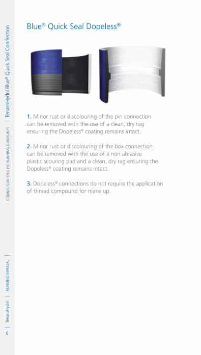
6
RUN
NIN
G M
AN
UA
LTe
naris
Hyd
rilC
oN
NeC
TIo
N S
peC
IfIC
RU
NN
ING
GU
IdeL
INeS
Tena
risH
ydril
Blu
e® Q
uick
Sea
l Con
nect
ion Blue® Quick Seal Dopeless®
1. Minor rust or discolouring of the pin connection can be removed with the use of a clean, dry rag ensuring the Dopeless® coating remains intact.
2. Minor rust or discolouring of the box connection can be removed with the use of a non abrasive plastic scouring pad and a clean, dry rag ensuring the Dopeless® coating remains intact.
3. Dopeless® connections do not require the application of thread compound for make up.

7
RUN
NIN
G M
AN
UA
LTe
naris
Hyd
ril
IDM
Cod
e G
DL0
0370
/3 /
Mar
ch 2
018
Co
NN
eCTI
oN
Spe
CIf
IC R
UN
NIN
G G
UID
eLIN
eS
Te
naris
Hyd
ril B
lue®
Qui
ck S
eal C
onne
ctio
n If for whatever reason dope has to be applied to Blue® Quick Seal Dopeless® connections whether both pin and box are Dopeless® or when mixing a doped connection with a Dopeless®, apply thread compound as indicated below.
non doPeleSS® PIn InTo doPeleSS® box
.Apply a thin coating of thread compound on all pin threads, seal and pin nose.
.Apply a thin coat of thread compound to box internal seal and torque shoulder.
.Do not fill dope pocket with thread compound.
doPeleSS® PIn InTo STandard box
.Apply a very thin coating of thread compound on all pin threads only.
.Do not dope pin seal or box connection.
doPeleSS® PIn InTo doPeleSS® box
.Apply a very thin layer of thread compound on all pin threads only.
.Do not dope pin seal or box connection.
StandardBox
Dopeless®
Box
See page 8
Dope Pin Threads, Seal& Shoulder. Dope Box Seal.
STANDARD PIN
Dope Pin Threads Only
Dope PinThreads Only
DOPELESS® PIN
If applying thread compound to Dopeless® connections use doped variant torque values.Contact Tenaris for torque values.

8
RUN
NIN
G M
AN
UA
LTe
naris
Hyd
rilC
oN
NeC
TIo
N S
peC
IfIC
RU
NN
ING
GU
IdeL
INeS
Tena
risH
ydril
Blu
e® Q
uick
Sea
l Con
nect
ion Thread Compound Application
If two non Dopeless® connections are to be assembled apply thread compound as indicated below.
1. Apply a thin coating of thread compound on the pin and box connections, fully covering all threads, seals, pin nose and box torque shoulder, the thread form should be fully visible.
2. Use approximately 50% of the quantity applied to the pin when doping the box.
3. Do not fill the dope pocket.
4. For Tenaris approved thread compounds, apply the friction factor indicated in TSH-MD-00.0002. For thread compounds other than those listed, apply the thread compound manufacturers indicated friction factor.
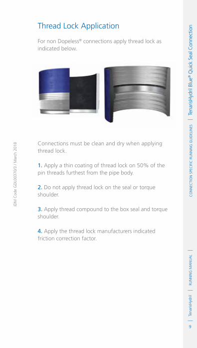
9
RUN
NIN
G M
AN
UA
LTe
naris
Hyd
ril
IDM
Cod
e G
DL0
0370
/3 /
Mar
ch 2
018
Co
NN
eCTI
oN
Spe
CIf
IC R
UN
NIN
G G
UID
eLIN
eS
Te
naris
Hyd
ril B
lue®
Qui
ck S
eal C
onne
ctio
n Thread Lock Application
For non Dopeless® connections apply thread lock as indicated below.
Connections must be clean and dry when applying thread lock.
1. Apply a thin coating of thread lock on 50% of the pin threads furthest from the pipe body.
2. Do not apply thread lock on the seal or torque shoulder.
3. Apply thread compound to the box seal and torque shoulder.
4. Apply the thread lock manufacturers indicated friction correction factor.

10
RUN
NIN
G M
AN
UA
LTe
naris
Hyd
rilC
oN
NeC
TIo
N S
peC
IfIC
RU
NN
ING
GU
IdeL
INeS
Tena
risH
ydril
Blu
e® Q
uick
Sea
l Con
nect
ion Blue® Quick Seal Dopeless®
Thread Lock
1. Ideally when running a Dopeless® string the connections to be thread locked should be the non Dopeless® variant with the connections cleaned of thread compound and completely dried, then thread lock and dope applied as per page 9.
2. When thread locking Dopeless® connections remove the Dopeless® coating from the threads on the pin connection where the thread lock is to be applied.
3. Leave the Dopeless® coating on the pin seal, torque shoulder and threads where no thread lock is to be applied.
4. Dopeless® boxes should be washed with hot water then dried prior to thread locking.
5. Thread lock should be applied to 50% of the pin threads immediately behind the seal area, as per the diagram in page 9.
6. When assembling Dopeless® connections with thread lock, apply the non Dopeless® torque values taken from the standard product data sheet.
7. Apply the thread lock manufacturers indicated friction factor.
8. The application of thread dope is not required.
9. Contact Tenaris for further information on the thread locking process.

11
RUN
NIN
G M
AN
UA
LTe
naris
Hyd
ril
IDM
Cod
e G
DL0
0370
/3 /
Mar
ch 2
018
Co
NN
eCTI
oN
Spe
CIf
IC R
UN
NIN
G G
UID
eLIN
eS
Te
naris
Hyd
ril B
lue®
Qui
ck S
eal C
onne
ctio
n Torque Application
1. The use of computer make up analysis equipment is strongly recommended when assembling Blue® Quick Seal connections.
2. Shoulder points for Blue® Quick Seal connection.
.Minimum 15% of optimum.
.Maximum 85% of optimum.
3. Reference torque should initially be set at 5% of optimum.
4. The dump valve should be set at optimum torque, verify correct operation on the pipe body prior to first make up.
5. Set the computer turns to 2 initially then adjust as necessary to attain good graph depiction.
6. Refer to the TenarisHydril running manual, make up acceptance section for further explanation.
7. The computer graph make up profile for Blue® Quick Seal connections should be similar to the ones below.

12
RUN
NIN
G M
AN
UA
LTe
naris
Hyd
rilC
oN
NeC
TIo
N S
peC
IfIC
RU
NN
ING
GU
IdeL
INeS
Tena
risH
ydril
Blu
e® Q
uick
Sea
l Con
nect
ion
8. Blue® Quick Seal connections have limited same size / weight interchange capability, if mixing weight /grade ensure compatibility of design and apply the lower torque values of the two connections.
9. Dopeless® connection torque values should be taken from the latest Dopeless® variant product data sheet.
10. When mixing standard doped and Dopeless® connections apply doped variant torque values.
11, Contact Tenaris for torque values.
TOR
QU
E *
1000
ft-
lbs
MAX. 49800
MAX. SHL 41225
OPT 48500
0
0
1.2
2.4
3.6
4.8
0.32 0.64 0.96 1.28
TURNS
MIN. 46015
MIN. SHL 7275
TOR
QU
E *
1000
ft-
lbs
MAX. 49800
MAX. SHL 41225
OPT 48500
0
0
1.2
2.4
3.6
4.8
0.32 0.64 0.96 1.28
TURNS
MIN. 46015
MIN. SHL 7275

13
RUN
NIN
G M
AN
UA
LTe
naris
Hyd
ril
IDM
Cod
e G
DL0
0370
/3 /
Mar
ch 2
018
Co
NN
eCTI
oN
Spe
CIf
IC R
UN
NIN
G G
UID
eLIN
eS
Te
naris
Hyd
ril B
lue®
Qui
ck S
eal C
onne
ctio
n Running 1. The use of a stabbing guide is strongly recommended.
2. The use of a weight compensator is strongly recommended for large OD or heavy pipe.
3. To avoid cross threading stab pipe in a smooth controlled fashion ensuring the pipe is vertical when doing so, continue to support and stabilise the pipe throughout the stabbing and make up operation.
4. Upon commencement of initial rotation use low RPM (5 RPM or below) in order to ensure the pipe has not cross threaded during stabbing.
5. If cross threading is evident, immediately reverse rotate the pipe, completely disassemble, clean and inspect both connections.
6. Maximum spin in speed should not exceed 10 RPM.
7. Apply power tong at low RPM (do not exceed 5 RPM) for final make up.

14
RUN
NIN
G M
AN
UA
LTe
naris
Hyd
rilC
oN
NeC
TIo
N S
peC
IfIC
RU
NN
ING
GU
IdeL
INeS
Tena
risH
ydril
Blu
e® Q
uick
Sea
l Con
nect
ion Pulling
1. Automatic stabbing system or stabber is highly recommended to maintain the pipe in a vertical position.
2. The use of a stabbing guide is recommended to assist in centralising the pin to prevent hang up.
3. A weight compensator is strongly recommended for large OD and heavy pipe.
4. Apply the back up tong jaw on the lower part, over the mill end of the coupling.
5. Apply power tong in low RPM (3-5 RPM) to break the connection, ensuring the pipe is stabilized during the break and spin out process.
6. Do not exceed 10 RPM during spin out.
7. Visual inspection is recommended to classify the thread condition. Any rejected connections should be clearly marked and segregated for further investigation.
8. For any non Dopeless® connections apply clean, dry thread protectors after applying storage compound on clean, dry connections.
9. Storage / thread compound should always be applied to standard connections post job, even rejects.
10. Do not apply storage compound to Dopeless® connections.
11. For long term storage of Dopeless® connections, refurbishment by qualified personnel is recommended.
12. Ensure clean, dry, Dopeless® protectors with seal rings correctly in place are installed.

1
RUN
NIN
G M
AN
UA
LTe
naris
Hyd
rilC
oN
NeC
TIo
N S
peC
IfIC
RU
NN
ING
GU
IdeL
INeS
Tena
risH
ydril
Blu
e® M
ax C
onne
ctio
n
IdM
Cod
e G
dL0
0367
/2 /
Mar
ch 2
018
TenarisHydril Blue® Max ConnectionScope
These guidelines apply specifically to the use of TenarisHydril Blue® Max connections. This document should be used in conjunction with the TenarisHydril Running Manual, which is the main document applicable to the running of all TenarisHydril premium connections.
References
.TenarisHydril Running Manual..Premium Connection Approved Thread Compounds TSH-MD-00.0002..Recommended guidelines for the field inspection of TenarisHydril connections, FSOG 13-005.
Equipment, Material & Documents
1. Verify the appropriate thread compound is available.
2. Refer to document TSH-MD-00.0002 for a list of compounds approved by Tenaris.
3. Latest version of the specific Product Data Sheet can be obtained from Tenaris web site. In case this is unavailable, request the data sheet from the local Technical Sales representative or [email protected].

2
RUN
NIN
G M
AN
UA
LTe
naris
Hyd
rilC
oN
NeC
TIo
N S
peC
IfIC
RU
NN
ING
GU
IdeL
INeS
Tena
risH
ydril
Blu
e® M
ax C
onne
ctio
n Pre-Running
1. Never move or handle pipe without the correct thread protectors securely in place.
2. Ensure connections are cleaned and free of all debris and / or contaminants, cleaning methods employed should conform to the recommendations contained within the TenarisHydril Running Manual.
3. Verify all pipe and accessories have genuine TenarisHydril manufactured connections.
4. Visually inspect threads and seal areas prior to running, ensuring no damage is evident.
5. Check condition of both pin and box Dopeless® coating ensuring no peel off or degradation has occurred.
6. Verify compatibility of the Blue® Max connection with any accessories such as cement heads, safety valves, cross overs, etc.
7. Blue® Max is a weight specific design and is therefore not interchangeable with other weights of the same OD.
8. Verify material grade of all accessories ensuring compatibility with main string.

3
RUN
NIN
G M
AN
UA
LTe
naris
Hyd
ril
IDM
Cod
e G
DL0
0367
/2 /
Mar
ch 2
018
Co
NN
eCTI
oN
Spe
CIf
IC R
UN
NIN
G G
UID
eLIN
eS
Te
naris
Hyd
ril B
lue®
Max
Con
nect
ion Blue® Max Configuration
Twin Start Thread4 TPI Hooked Thread
SEAL
DopE pockEt
torquEShouLDEr

4
RUN
NIN
G M
AN
UA
LTe
naris
Hyd
rilC
oN
NeC
TIo
N S
peC
IfIC
RU
NN
ING
GU
IdeL
INeS
Tena
risH
ydril
Blu
e® M
ax C
onne
ctio
n Inspection
1. Inspection criteria for all TenarisHydril connections is as outlined in the Field Service Operative Guideline FSOG 13-005.
2. Pay particular attention to seal areas.
3. Ensure the pin nose has no tears, gouges or raised metal.
4. Ensure the pin and box torque shoulders have no dents, tears or raised material which could interfere with correct assembly.
Blue® Max Dopeless®
1. Minor rust or discolouring of the pin connection can be removed with the use of a clean, dry rag ensuring the Dopeless® coating remains intact.
2. Minor rust or discolouring of the box connection can be removed with the use of a non abrasive plastic scouring pad and a clean, dry rag ensuring the Dopeless® coating remains intact.
3. Dopeless® connections do not require the application of thread compound for make up.

5
RUN
NIN
G M
AN
UA
LTe
naris
Hyd
ril
IDM
Cod
e G
DL0
0367
/2 /
Mar
ch 2
018
Co
NN
eCTI
oN
Spe
CIf
IC R
UN
NIN
G G
UID
eLIN
eS
Te
naris
Hyd
ril B
lue®
Max
Con
nect
ion If for whatever reason thread compound has to
be applied to Blue® Max Dopeless® connections, whether both pin and box are Dopeless® or when mixing a doped connection with a Dopeless®, apply thread compound as indicated below.
NoN DopELESS® piN iNto DopELESS® box
.Apply a thin coating of thread compound on all pin threads, seal and pin nose.
.Apply a thin coat of thread compound to box seal and torque shoulder.
.Do not fill the dope pocket with thread compound.
DopELESS® piN iNto StANDArD box
.Apply a very thin coating of thread compound on all pin threads only.
.Do not dope pin seal or box connection.
DopELESS® piN iNto DopELESS® box
.Apply a very thin layer of thread compound on all pin threads only.
.Do not dope pin seal or box connection.
StandardBox
Dopeless®
Box
See page 7
Dope Pin Threads, Seal& Shoulder. Dope Box Seal.
STANDARD PIN
Dope Pin Threads Only
Dope PinThreads Only
DOPELESS® PIN
If applying thread compound to Dopeless® connections use the doped variant torque values.Contact Tenaris for torque values.

6
RUN
NIN
G M
AN
UA
LTe
naris
Hyd
rilC
oN
NeC
TIo
N S
peC
IfIC
RU
NN
ING
GU
IdeL
INeS
Tena
risH
ydril
Blu
e® M
ax C
onne
ctio
n Blue® Max Dopeless® Thread Lock
1. Ideally when running a Dopeless® string the connections to be thread locked should be the non Dopeless® variant with the connections cleaned of thread compound and completely dried, then thread lock and dope applied as per page 8.
2. When thread locking Dopeless® connections remove the Dopeless® coating from the threads on the pin connection where thread lock is to be applied.
3. Leave the Dopeless® coating on the pin seal, torque shoulder and threads where no thread lock is to be applied.
4. Dopeless® boxes should be washed with hot water then dried prior to thread locking.
5. Thread lock should be applied to 50% of the pin threads immediately behind the seal area, as per the diagram in page 8.
6. When assembling Dopeless® connections with thread lock, apply the non Dopeless® torque values taken from the standard product data sheet.
7. Apply the thread lock manufacturers indicated friction factor.
8. The application of thread dope is not required.
9. Contact Tenaris for further information on the thread locking process.

7
RUN
NIN
G M
AN
UA
LTe
naris
Hyd
ril
IDM
Cod
e G
DL0
0367
/2 /
Mar
ch 2
018
Co
NN
eCTI
oN
Spe
CIf
IC R
UN
NIN
G G
UID
eLIN
eS
Te
naris
Hyd
ril B
lue®
Max
Con
nect
ion Thread Compound Application
If two non Dopeless® connections are to be assembled apply thread compound as indicated below.
1. Apply a thin coating of thread compound on the pin and box connections, fully covering all threads, seals, pin nose and box torque shoulder, the thread form should be fully visible.
2. Use approximately 50% of the quantity applied to the pin when doping the box.
3. Do not fill the dope pocket.
4. For Tenaris approved thread compounds, apply the friction factor indicated in TSH-MD-00.0002. For thread compounds other than those listed, apply the thread compound manufacturers indicated friction factor.

8
RUN
NIN
G M
AN
UA
LTe
naris
Hyd
rilC
oN
NeC
TIo
N S
peC
IfIC
RU
NN
ING
GU
IdeL
INeS
Tena
risH
ydril
Blu
e® M
ax C
onne
ctio
n Thread Lock Application
For non Dopeless® connections apply thread lock as indicated below.
Connections must be clean and dry when applying thread lock.
1. Apply a thin coating of thread lock on 50% of the pin threads furthest from the pipe body.
2. Do not apply thread lock on the seal or torque shoulder.
3. Apply thread compound to the box seal and torque shoulder.
4. Do not fill the dope pocket.
5. Apply the thread lock manufacturers indicated friction factor.
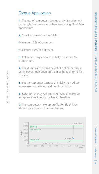
9
RUN
NIN
G M
AN
UA
LTe
naris
Hyd
ril
IDM
Cod
e G
DL0
0367
/2 /
Mar
ch 2
018
Co
NN
eCTI
oN
Spe
CIf
IC R
UN
NIN
G G
UID
eLIN
eS
Te
naris
Hyd
ril B
lue®
Max
Con
nect
ion Torque Application
1. The use of computer make up analysis equipment is strongly recommended when assembling Blue® Max connections.
2. Shoulder points for Blue® Max.
.Minimum 15% of optimum.
.Maximum 85% of optimum.
3. Reference torque should initially be set at 5% of optimum.
4. The dump valve should be set at optimum torque, verify correct operation on the pipe body prior to first make up.
5. Set the computer turns to 2 initially then adjust as necessary to attain good graph depiction.
6. Refer to TenarisHydril running manual, make up acceptance section for further explanation.
7. The computer make up profile for Blue® Max should be similar to the ones below.
TOP SHD
TOR
QU
E
0.00 0.50 1.00 1.50 2.00 2.50 3.00 3.50 4.00
0
10000
20000
30000
40000
50000
59290
TURNS
MAX 53900
MIN SHL 7350
MAX SHL 41650
OPT 49000

10
RUN
NIN
G M
AN
UA
LTe
naris
Hyd
rilC
oN
NeC
TIo
N S
peC
IfIC
RU
NN
ING
GU
IdeL
INeS
Tena
risH
ydril
Blu
e® M
ax C
onne
ctio
n
8. Blue® Max connections are weight specific design therefore are not interchangeable between different weights of the same OD.
9. When assembling Dopeless® connections the torques applied must be taken from the Dopeless® variant product data sheet.
10. When mixing standard doped and Dopeless® connections apply doped variant torque values.
11. Contact Tenaris for torque values.
Running
1. The use of a stabbing guide is strongly recommended.
2. The use of a weight compensator is strongly recommended for chrome, large OD or heavy pipe.
3. To avoid cross threading stab pipe in a smooth controlled fashion ensuring the pipe is vertical when doing so, continue to support and stabilise the pipe throughout the stabbing and make up operation.
TOP SHDTOR
QU
E
0.00 0.50 1.00 1.50 2.00 2.50 3.00 3.50 4.00
-1
10000
20000
30000
40000
50000
59290
TURNS
MAX 53900
MIN SHL 7350
MAX SHL 41650
OPT 49000

11
RUN
NIN
G M
AN
UA
LTe
naris
Hyd
ril
IDM
Cod
e G
DL0
0367
/2 /
Mar
ch 2
018
Co
NN
eCTI
oN
Spe
CIf
IC R
UN
NIN
G G
UID
eLIN
eS
Te
naris
Hyd
ril B
lue®
Max
Con
nect
ion 4. Upon commencement of initial rotation use low
RPM (5 RPM or below) in order to ensure the pipe has not cross threaded during stabbing.
5. If cross threading is evident, immediately reverse rotate the pipe, completely disassemble, clean and inspect both connections.
6. Maximum spin in speed should not exceed 10 RPM.
7. Apply power tong at low rpm (do not exceed 5 RPM), for final make up.
8. Walk chrome pipe all the way in to hand tight, then apply tong for final make up.
Pulling
1. Automatic stabbing system or stabber is highly recommended to maintain the pipe in a vertical position.
2. The use of a stabbing guide is recommended to assist in centralising the pin to prevent hang up.
3. A weight compensator is strongly recommended for chrome, large OD and heavy pipe.
4. Apply the back up tong jaw on the lower part, over the mill end of the coupling.
5. Apply power tong in low RPM (3-5 RPM) to break the connection, ensuring the pipe is stabilised during the break and spin out process.
6. Do not exceed 10 RPM during spin out.
7. Walk chrome pipe all the way out by hand after initial break.

12
RUN
NIN
G M
AN
UA
LTe
naris
Hyd
rilC
oN
NeC
TIo
N S
peC
IfIC
RU
NN
ING
GU
IdeL
INeS
Tena
risH
ydril
Blu
e® M
ax C
onne
ctio
n 8. Visual inspection is recommended to classify the thread condition. Any rejected connections should be clearly marked and segregated for further investigation.
9. For any non Dopeless® connections apply clean, dry thread protectors after applying storage compound on clean, dry connections.
10. Storage / thread compound should always be applied to standard connections post job, even rejects.
11. Do not apply storage compound to Dopeless® connections.
12. For long term storage of Dopeless® connections, refurbishment by qualified personnel is recommended.
13. Ensure clean, dry, Dopeless® protectors with seal rings correctly in place are installed.
1
RUN
NIN
G M
AN
UA
LTe
naris
Hyd
rilC
oN
NeC
TIo
N S
peC
IfIC
RU
NN
ING
GU
IdeL
INeS
Tena
risH
ydril
Blu
e® R
iser C
onne
ctio
n
IdM
Cod
e G
dL0
0368
/4 /
Mar
ch 2
018
TenarisHydrilBlue® Riser ConnectionScope
These guidelines apply specifically to the use of TenarisHydril Blue® Riser connections. This document should be used in conjunction with the TenarisHydril Running Manual, which is the main document applicable to the running of all TenarisHydril premium connections.
References
.TenarisHydril Running Manual..Premium Connection Approved Thread Compounds TSH-MD-00.0002..Recommended guidelines for the field inspection of TenarisHydril connections, FSOG 13-005.
Equipment, Material & Documents
1. Verify the appropriate thread compound is available.
2. Refer to document TSH-MD-00.0002 for a list of compounds approved by Tenaris.
3. Latest version of the specific Product Data Sheet can be obtained from Tenaris web site. In case this is unavailable, request the data sheet from the local Technical Sales representative or [email protected].

2
RUN
NIN
G M
AN
UA
LTe
naris
Hyd
rilC
oN
NeC
TIo
N S
peC
IfIC
RU
NN
ING
GU
IdeL
INeS
Tena
risH
ydril
Blu
e® R
iser C
onne
ctio
n 4. Slip type elevators with low marking dies should be used.
5. Tong, back up tong and rotary slips should be dressed with low marking dies.
6. Specific tools required for successful running, pulling and inspection of Blue® Riser connection:.Depth gauge.
Pre-Running
1. Never move or handle pipe without the correct thread protectors securely in place.
2. Ensure connections are cleaned and free of all debris and / or contaminants, cleaning methods employed should conform to the recommendations contained within the TenarisHydril Running Manual.
3. Verify all pipe and accessories have genuine TenarisHydril manufactured connections.
4. Visually inspect threads and seal areas prior to running, ensuring no damage is evident.
5. Verify compatibility of the Blue® Riser connection with accessories such as pup joints.
6. Connection weight interchange compatibility is indicated in the TenarisHydril premium connections catalogue.
7. Verify material grade of all accessories ensuring compatibility with main string.
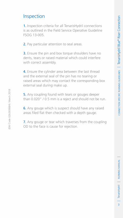
3
RUN
NIN
G M
AN
UA
LTe
naris
Hyd
rilC
oN
NeC
TIo
N S
peC
IfIC
RU
NN
ING
GU
IdeL
INeS
Tena
risH
ydril
Blu
e® R
iser C
onne
ctio
n
IdM
Cod
e G
dL0
0368
/4 /
Mar
ch 2
018
Inspection
1. Inspection criteria for all TenarisHydril connections is as outlined in the Field Service Operative Guideline FSOG 13-005.
2. Pay particular attention to seal areas.
3. Ensure the pin and box torque shoulders have no dents, tears or raised material which could interfere with correct assembly.
4. Ensure the cylinder area between the last thread and the external seal of the pin has no tearing or raised areas which may contact the corresponding box external seal during make up.
5. Any coupling found with tears or gouges deeper than 0.020" / 0.5 mm is a reject and should not be run.
6. Any gouge which is suspect should have any raised areas filed flat then checked with a depth gauge.
7. Any gouge or tear which traverses from the coupling OD to the face is cause for rejection.

4
RUN
NIN
G M
AN
UA
LTe
naris
Hyd
rilC
oN
NeC
TIo
N S
peC
IfIC
RU
NN
ING
GU
IdeL
INeS
Tena
risH
ydril
Blu
e® R
iser C
onne
ctio
n Blue® Riser Configuration
4 TPI ≤ 11 7/8"3 TPI ≥ 12 3/4"

5
RUN
NIN
G M
AN
UA
LTe
naris
Hyd
rilC
oN
NeC
TIo
N S
peC
IfIC
RU
NN
ING
GU
IdeL
INeS
Tena
risH
ydril
Blu
e® R
iser C
onne
ctio
n
IdM
Cod
e G
dL0
0368
/4 /
Mar
ch 2
018
ExtErnal SEal
CylindriCal arEa
StrESS rEliEf
groovES
torquE ShouldEr
r-arCh™
intErnal SEal
dopE poCkEt

6
RUN
NIN
G M
AN
UA
LTe
naris
Hyd
rilC
oN
NeC
TIo
N S
peC
IfIC
RU
NN
ING
GU
IdeL
INeS
Tena
risH
ydril
Blu
e® R
iser C
onne
ctio
n Thread Compound Application
1. Apply a liberal coating of thread compound on the pin connection, fully covering all threads, seals and pin nose.
2. Unlike other TenarisHydril connections it is not necessary to see the thread profile after applying thread compound.
3. Apply thread compound liberally to the box seals and threads.
4. Do not fill the dope pocket or R-Arch™.
5. If required an increased quantity of thread compound can be applied to both pin and box connections.
6. For Tenaris approved thread compounds, apply the friction factor indicated in TSH-MD-00.0002. For thread compounds other than those listed, apply the thread compound manufacturers indicated friction factor.

7
RUN
NIN
G M
AN
UA
LTe
naris
Hyd
rilC
oN
NeC
TIo
N S
peC
IfIC
RU
NN
ING
GU
IdeL
INeS
Tena
risH
ydril
Blu
e® R
iser C
onne
ctio
n
IdM
Cod
e G
dL0
0368
/4 /
Mar
ch 2
018
Torque Application
1. The use of computer make up analysis equipment is strongly recommended when assembling Blue® Riser connections.
2. Shoulder points for Blue® Riser connections.
.Minimum 15% of optimum.
.Maximum 85% of optimum.
3. Reference torque should initially be set at 5% of optimum.
4. The dump valve should be set at optimum torque, verify correct operation on the pipe body prior to first make up.
5. The connection should take approximately three turns from stabbing to power tight assembly.
6. Set the computer turns to 3 initially then adjust as necessary to attain good graph depiction.
7. Refer to the TenarisHydril Running Manual, make up acceptance section for further explanation.
8. The computer make up profile for Blue® Riser connections should be similar to the ones below.

8
RUN
NIN
G M
AN
UA
LTe
naris
Hyd
rilC
oN
NeC
TIo
N S
peC
IfIC
RU
NN
ING
GU
IdeL
INeS
Tena
risH
ydril
Blu
e® R
iser C
onne
ctio
n
9. Blue® Riser connections have limited same size / weight interchange capability, if mixing weight / grade ensure compatibility of design and apply the lower torque values of the two connections.
TOP SHD
TOR
QU
E
3.00 3.50
0
5000
10000
15000
20000
25000
30000
35000
40205
4.00 4.50 5.00 5.50 6.00 6.50 7.00
TURNS
MAX. 36500
MAX. SHL 28900
OPT 34000
MIN. SHL 5100
TOP SHD
TOR
QU
E
3.00 3.50
0
5000
10000
15000
20000
25000
30000
35000
40205
4.00 4.50 5.00 5.50 6.00 6.50 7.00
TURNS
MAX. 36500
MAX. SHL 28900
OPT 34000
MIN. SHL 5100

9
RUN
NIN
G M
AN
UA
LTe
naris
Hyd
rilC
oN
NeC
TIo
N S
peC
IfIC
RU
NN
ING
GU
IdeL
INeS
Tena
risH
ydril
Blu
e® R
iser C
onne
ctio
n
IdM
Cod
e G
dL0
0368
/4 /
Mar
ch 2
018
Running 1. It is strongly recommended to use slip type elevators with low marking dies.
2. The use of collar lift elevators abutting the coupling face is restricted to a maximum lift of a single joint.
3. The use of a stabbing guide is strongly recommended.
4. The use of a weight compensator is strongly recommended for large OD and heavy pipe.
5. To avoid cross threading stab pipe in a smooth controlled fashion ensuring the pipe is vertical when doing so, continue to support and stabilise the pipe throughout the stabbing and make up operation.
6. Upon commencement of initial rotation use low RPM (5 RPM or below) in order to ensure the pipe has not cross threaded during stabbing.
7. If cross threading is evident, immediately reverse rotate the pipe, completely disassemble, clean and inspect both connections.
8. Maximum spin in speed should not exceed 5 RPM.
9. Final make up should be conducted between 3 RPM minimum and 5 RPM maximum.
10. Ensure rotating and back up tong have low marking dies to prevent damage to the pipe body.
11. Gouges or tears inflicted on the pipe body should not exceed 0.020" / 0.5 mm.

10
RUN
NIN
G M
AN
UA
LTe
naris
Hyd
rilC
oN
NeC
TIo
N S
peC
IfIC
RU
NN
ING
GU
IdeL
INeS
Tena
risH
ydril
Blu
e® R
iser C
onne
ctio
n
Penetration depth 0.035"
Penetration depth 0.003"

11
RUN
NIN
G M
AN
UA
LTe
naris
Hyd
rilC
oN
NeC
TIo
N S
peC
IfIC
RU
NN
ING
GU
IdeL
INeS
Tena
risH
ydril
Blu
e® R
iser C
onne
ctio
n
IdM
Cod
e G
dL0
0368
/4 /
Mar
ch 2
018
Pulling
1. Automatic stabbing system or stabber is highly recommended to maintain the pipe in a vertical position.
2. The use of a stabbing guide is recommended to assist in centralising the pin to prevent hang up.
3. Apply the back up tong jaw below the centre of the coupling.
4. Never position the tong near the coupling face or over the R-Arch™.
5. Apply power tong in low RPM (5 RPM Max) to break and spin out the connection, ensuring the pipe is stabilized during the break out process.
6. Visual inspection is recommended to classify the thread condition. Any rejected connections should be clearly marked and segregated for further investigation.
7. Apply clean, dry thread protectors after applying storage compound on clean, dry connections.
8. Storage / thread compound should always be applied to connections post job, even rejects.

12
RUN
NIN
G M
AN
UA
LTe
naris
Hyd
rilC
oN
NeC
TIo
N S
peC
IfIC
RU
NN
ING
GU
IdeL
INeS
Tena
risH
ydril
Blu
e® R
iser C
onne
ctio
n
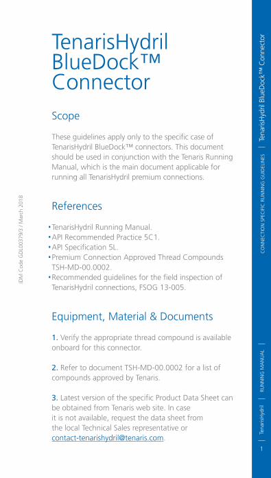
1
RUN
NIN
G M
AN
UA
LTe
naris
Hyd
rilC
oN
NeC
TIo
N S
peC
IfIC
RU
NN
ING
GU
IdeL
INeS
Tena
risH
ydril
Blu
edoc
k™ C
onne
ctor
IdM
Cod
e G
dL0
0379
/3 /
Mar
ch 2
018
TenarisHydril BlueDock™ ConnectorScope
These guidelines apply only to the specific case of TenarisHydril BlueDock™ connectors. This document should be used in conjunction with the Tenaris Running Manual, which is the main document applicable for running all TenarisHydril premium connections.
References
.TenarisHydril Running Manual..API Recommended Practice 5C1..API Specification 5L..Premium Connection Approved Thread Compounds TSH-MD-00.0002..Recommended guidelines for the field inspection of TenarisHydril connections, FSOG 13-005.
Equipment, Material & Documents
1. Verify the appropriate thread compound is available onboard for this connector.
2. Refer to document TSH-MD-00.0002 for a list of compounds approved by Tenaris.
3. Latest version of the specific Product Data Sheet can be obtained from Tenaris web site. In caseit is not available, request the data sheet fromthe local Technical Sales representative [email protected].

2
RUN
NIN
G M
AN
UA
LTe
naris
Hyd
rilC
oN
NeC
TIo
N S
peC
IfIC
RU
NN
ING
GU
IdeL
INeS
Tena
risH
ydril
Blu
edoc
k™ C
onne
ctor
4. There are two designs of BlueDock™ connector; Metal To Metal (MTM) and Elastomeric (ELS) seal variants.
5. Both MTM and ELS seal designs can also be supplied with a sea water exclusion seal (SWS).
6. Additionally BlueDock™ connector has two designations of each variant, High Range (HR) and Low Range (LR), these designations are dependent on wall thickness (WT).
7. 20” LR is the only variant without a retainer groove at the pin external shoulder.
8. Verify the compatibility of the BlueDock™ connector with accessories such as pup joints, etc.
9. Ensure accessories such as O-rings (elastomeric seal variant), spare Anti Rotation Keys (ARK’s) and ARK installation tools are available on the rig prior to operation commencement.
10. Specific tools required for successful running or pulling of BlueDock™ connectors
.Feeler gauges from 0.05 mm to 1 mm.Allen key: 5 mm.Spare ARKs and hexagonal bolts.Hammer.Chisel

3
RUN
NIN
G M
AN
UA
LTe
naris
Hyd
ril
IDM
Cod
e G
DL0
0379
/3 /
Mar
ch 2
018
Co
NN
eCTI
oN
Spe
CIf
IC R
UN
NIN
G G
UID
eLIN
eS
Te
naris
Hyd
ril B
lueD
ock™
Con
nect
or Pre-Running
1. Check weld cord, ensuring the elevators can pass over to seat against the connector.
2. The following connector information will be hard stamped on the connector OD:
.Seal Type.Range: Low Range (LR) or High Range (HR).OD.Connector SMYS.Manufacturing Facility.Manufacturing Quarter.Traceability Numbers.
Connector Color Coding
HR
HR
HR
HR
HR
HR
HR
HR
LR
LR
LR
LR
LR
LR
LR
LR
MTM
MTM
ELS
ELS
MTM SWS
MTM SWS
ELS SWS
ELS SWS
MTM
MTM
ELS
ELS
MTM SWS
MTM SWS
ELS SWS
ELS SWS
70 Ksi
90 Ksi
70 Ksi
90 Ksi
70 Ksi
90 Ksi
70 Ksi
90 Ksi
70 Ksi
90 Ksi
70 Ksi
90 Ksi
70 Ksi
90 Ksi
70 Ksi
90 Ksi
Blue
Grey
Yellow
Brown
Green
Purple
Silver
Red
Orange
Pink
Violet
Black
Sky-Blue
White
Magenta
Bright Green
COLOuRRANGE SEAL GRADE
One 50mm wide band painted round the connector OD indicating; Range, Seal Type and Connector Grade.

4
RUN
NIN
G M
AN
UA
LTe
naris
Hyd
rilC
oN
NeC
TIo
N S
peC
IfIC
RU
NN
ING
GU
IdeL
INeS
Tena
risH
ydril
Blu
edoc
k™ C
onne
ctor
3. The pipe grade will be stenciled in the pipe ID no less than 6” back from the pipe end.
4. Alternatively / additionally if requested by customer during manufacture a colour code may be painted in the pipe ID:
X46
X52
X56
X60
X65
X70
X80
Black
Green
Blue
Red
White
Purple
Yellow
COLOuRGRADE
5. Make note of the connector and pipe grade, there should be a disparity.
6. Shift ARK(s) to the unlocked position and tighten bolt then remove the protectors.
7. Check if ARK(s) are moving freely, if not loosen with the aid of anti-seize spray.
8. Ensure the connectors are cleaned and free of all debris and / or contaminants, cleaning methods employed should conform to the recommendations contained within the TenarisHydril running manual.
9. Visually inspect threads, shoulders and seal areas as per field inspection guideline FSOG 13-005, prior to running ensuring no damage is evident.
10. Check the condition and fit of the O-ring (Elastomeric and SWS variants).
11. Pipe should arrive with the O-ring installed, if not check the fit of O-rings onboard.

5
RUN
NIN
G M
AN
UA
LTe
naris
Hyd
ril
IDM
Cod
e G
DL0
0379
/3 /
Mar
ch 2
018
Co
NN
eCTI
oN
Spe
CIf
IC R
UN
NIN
G G
UID
eLIN
eS
Te
naris
Hyd
ril B
lueD
ock™
Con
nect
or
12. Ensure there are spare O-rings on board.
13. Clean, dry then replace protectors.
14. Re-set all ARK(s) and secure in order to prevent protectors backing off when pipe is moved.
15. Never move or handle pipe without protectors securely in place.
16. Check the number of ARK(s) of each connector; one, two or three as per customer specification.
17. Verify the material grade of any pups or accessories is compatible with main string.
18. Pay particular attention and note the type of connector on each item.
Inspection
1. Check box and pin connectors for mashes or out of round, large OD connectors can be susceptible to handling damage such as mashes, dents or ovality.
2. Visually inspect all connectors as per Tenaris document, FSOG 13-005.
3. Ensure the pin and box shoulders have no dents, tears or raised material which could interfere with correct assembly.
4. Ensure there are no gouges or raised material on the alignment guide areas.
5. Pay particular attention to MTM seal areas, any damage witnessed is cause for rejection.
6. Check O-ring groove has no dents, mashes or gouges which would preclude correct installation of the ring.

6
RUN
NIN
G M
AN
UA
LTe
naris
Hyd
rilC
oN
NeC
TIo
N S
peC
IfIC
RU
NN
ING
GU
IdeL
INeS
Tena
risH
ydril
Blu
edoc
k™ C
onne
ctor
Weld
Cord
optional
sea Water
exClusion
seal
7. Check O–ring has no abrasions, cuts or tears, if found replace with a new ring ensuring it is correctly seated.
8. Check function of Anti Rotation Keys (ARK) to ensure ease of use whilst RIH.
9. It is advisable to use an anti-corrosion spray on the ARK(s) to prevent seizure whilst in storage.
10. Alternatively a storage grease such as Kendex can be applied.
BlueDock™ Configuration

7
RUN
NIN
G M
AN
UA
LTe
naris
Hyd
ril
IDM
Cod
e G
DL0
0379
/3 /
Mar
ch 2
018
Co
NN
eCTI
oN
Spe
CIf
IC R
UN
NIN
G G
UID
eLIN
eS
Te
naris
Hyd
ril B
lueD
ock™
Con
nect
or
alignment guide
alignment guide
mtm seal
dope poCket
elastomeriC
seal
dope poCket
retainer
external shoulder
no retainer
groove on 20” lr
alignment guide
alignment guide
three start
hooked thread

8
RUN
NIN
G M
AN
UA
LTe
naris
Hyd
rilC
oN
NeC
TIo
N S
peC
IfIC
RU
NN
ING
GU
IdeL
INeS
Tena
risH
ydril
Blu
edoc
k™ C
onne
ctor
Thread Compound Application
1. Ensure all connector surfaces are free of all contamination / debris and completely dry prior to doping, ensure any previously applied storage compound is completely removed.
2. Do not use solvents on Elastomeric or Sea Water Exclusion Seals as they may degrade the O-ring.
3. For Tenaris approved thread compounds, reference document TSH-MD-00.0002.
4. Always use a new unopened pail of thread compound, ensuring it is completely homogenised prior to use.
5. PIN END: Apply a thin even coat of running compound, covering the full thread area, seal surfaces (MTM, ELS and / or SWS), pin nose and torque shoulder. The thread form should be clearly visible.
6. Do not apply dope on the dope pocket nor external alignment guide.
7. BOX END: Apply an even coat of running compound covering the full thread area, seal surfaces (MTM, ELS and / or SWS) and torque shoulder. The thread form should be clearly visible.
8. Do not fill dope pockets or stress relief groove at box shoulder.

9
RUN
NIN
G M
AN
UA
LTe
naris
Hyd
ril
IDM
Cod
e G
DL0
0379
/3 /
Mar
ch 2
018
Co
NN
eCTI
oN
Spe
CIf
IC R
UN
NIN
G G
UID
eLIN
eS
Te
naris
Hyd
ril B
lueD
ock™
Con
nect
or
9. Do not pack the O-ring causing dope to encroach under the ring (Elastomeric and SWS variant).
10. For Tenaris approved thread compounds, apply the friction factor indicated in TSH-MD-00.0002. For thread compounds other than those listed, apply the thread compound manufacturers indicated friction factor.
Thread Lock Application
1. Ensure the connectors are completely clean and dry prior to applying thread lock.
2. Apply thread lock to 50% of the threads behind the pin seal.
3. Do not apply thread lock onto the seal.
4. Apply thread compound to SWS area.
5. Apply an even coat of running compound to the box torque shoulder and seal surface.
6. Do not fill dope pockets or stress relief groove at box shoulder.
7. Apply the thread lock manufacturers indicated friction factor.

10
RUN
NIN
G M
AN
UA
LTe
naris
Hyd
rilC
oN
NeC
TIo
N S
peC
IfIC
RU
NN
ING
GU
IdeL
INeS
Tena
risH
ydril
Blu
edoc
k™ C
onne
ctor
Torque Application
1. The use of computer make up analysis equipment is recommended when assembling BlueDock™ MTM seal connectors.
2. Shoulder points for BlueDock™ connectors.
.Minimum 30% of optimum.
.Maximum 85% of optimum.
3. A BlueDock™ connector assembles within ¾ of a turn from stabbing to power tight make up.
4. For accurate graph definition it is important to set the horizontal scale (turns) to 1 or below.
5. Reference torque should be set at zero.
6. The dump valve should be set at optimum torque, verify correct operation on the pipe body prior to first make up.
7. The graphs below correspond to the make up operation of the same connector displayed with three different turn spans.
8. Quite different profiles can be obtained by changing the turn span of the graph.
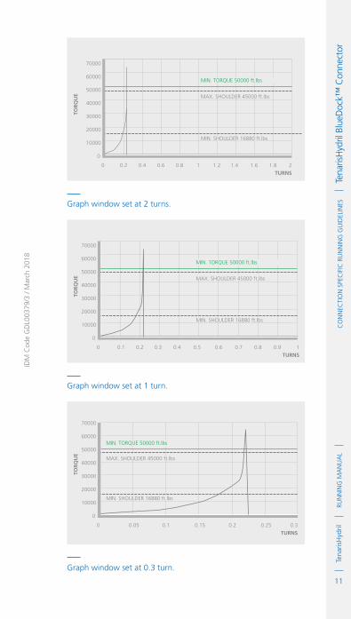
11
RUN
NIN
G M
AN
UA
LTe
naris
Hyd
ril
IDM
Cod
e G
DL0
0379
/3 /
Mar
ch 2
018
Co
NN
eCTI
oN
Spe
CIf
IC R
UN
NIN
G G
UID
eLIN
eS
Te
naris
Hyd
ril B
lueD
ock™
Con
nect
or
TOR
QU
E
0
0
10000
20000
30000
40000
50000
60000
70000
0.2 0.4 0.6 0.8 1 1.2 1.4 1.6 1.8 2
TURNS
MIN. SHOULDER 16880 ft.lbs
MIN. TORQUE 50000 ft.lbs
MAX. SHOULDER 45000 ft.lbs
TOR
QU
E
0
0
10000
20000
30000
40000
50000
60000
70000
0.1 0.2 0.3 0.4 0.5 0.6 0.7 0.8 0.9 1
TURNS
MIN. SHOULDER 16880 ft.lbs
MIN. TORQUE 50000 ft.lbs
MAX. SHOULDER 45000 ft.lbs
TOR
QU
E
0
0
10000
20000
30000
40000
50000
60000
70000
0.05 0.1 0.15 0.2 0.25 0.3
TURNS
MIN. SHOULDER 16880 ft.lbs
MIN. TORQUE 50000 ft.lbs
MAX. SHOULDER 45000 ft.lbs
Graph window set at 2 turns.
Graph window set at 1 turn.
Graph window set at 0.3 turn.

12
RUN
NIN
G M
AN
UA
LTe
naris
Hyd
rilC
oN
NeC
TIo
N S
peC
IfIC
RU
NN
ING
GU
IdeL
INeS
Tena
risH
ydril
Blu
edoc
k™ C
onne
ctor
9. The second and third graphs display an obvious clarity advantage.
10. Once made up the external shoulders can be used as a visual guide of correct assembly.
11. The external shoulder can be used as a visual guide of correct assembly. Once assembled a 0.30mm feeler gauge should be used to check the gap between box and pin face at several positions around the circumference, the feeler gauge should not fit the gap at 1 of the positions checked. If the the 0.30mm feeler gauge fits any one of the positions checked try a 0.35mm feeler gauge which should not fit, if it does the assembly cannot be accepted.
Running 1. Alignment is critical for all pipe running operations, with large OD being even more so. Ensure travelling block / top drive is aligned with the rotary.
2. A misalignment of 20% of the connector OD is excessive and must be corrected.
3. A stabbing guide is highly recommended to allow controlled, safe stabbing.
4. The use of a weight compensator is recommended.
5. Stab pipe in a smooth controlled fashion, ensuring elevators are slackened off from the connector.
6. Ensure pipe is stabilised during stabbing and make up, this is especially important in windy conditions and if running on a floating installation.

13
RUN
NIN
G M
AN
UA
LTe
naris
Hyd
ril
IDM
Cod
e G
DL0
0379
/3 /
Mar
ch 2
018
Co
NN
eCTI
oN
Spe
CIf
IC R
UN
NIN
G G
UID
eLIN
eS
Te
naris
Hyd
ril B
lueD
ock™
Con
nect
or
7. Once stabbed and stabilised the make up should be conducted in a single continuous operation without starts and stops until optimum torque is attained.
8. Ensure ARK(s) are in the unlocked position prior to stabbing.
9. Apply Low gear and make up below 5 RPM but no slower than 2 RPM.
10. Apply the torque indicated in the appropriate data sheet ensuring an acceptable make up is attained as previously described.
11. Slacken the fixing bolt on the open ARK(s) and hammer into position.
12. Tighten ARK bolt to lock in position.
13. Once assembled scribe a longitudinal line across both connectors as a visual reference.
14. If a situation arises where an O-ring and / or ARK(s) requires replacing, do so away from well bore.
15. BlueDock™ connector metal to metal and elastomeric seal variants are not interchangeable.
16. BlueDock™ connector has limited same OD interchange capability, dependent upon wall thickness.
17. Low Range (LR) and High Range (HR) connectors of the same diameter are not interchangeable.

14
RUN
NIN
G M
AN
UA
LTe
naris
Hyd
rilC
oN
NeC
TIo
N S
peC
IfIC
RU
NN
ING
GU
IdeL
INeS
Tena
risH
ydril
Blu
edoc
k™ C
onne
ctor
Anti Rotation Key (ARK) Function
1. Completely loosen lock bolt and knock into place.
2. Ensure all hammer blows contact the ARK strike face parallel to the face. Glancing blows or angled strikes can cause damage to the ARK.
3. Stop hammering Ark as soon as it is fully set to prevent breakage.
4. Ensure the ARK(s) are locked in place by the lock bolt using a hexagonal key.
Anti Rotation Key (ARK)
ARK UNSET KNOCK ARKDOWN INTO PLACE
ARK FULLY SET

15
RUN
NIN
G M
AN
UA
LTe
naris
Hyd
ril
IDM
Cod
e G
DL0
0379
/3 /
Mar
ch 2
018
Co
NN
eCTI
oN
Spe
CIf
IC R
UN
NIN
G G
UID
eLIN
eS
Te
naris
Hyd
ril B
lueD
ock™
Con
nect
or
ARK set and locked in position
5. The ARK(s) fit snug into the key guide.
6. Cover with grease to prevent corrosion seizure.
Pulling
1. Alignment is equally as critical for pulling as it is for running pipe.
2. Ensure travelling block / top drive is aligned with the hole, 20% deflection is excessive.
3. The use of a weight compensator is recommended.
4. unlock the ARK(s) bolt with the use of a hexagonal key.
5. Move the ARK(s) to the unlocked position and tighten lock bolt.
6. Ensure all ARK(s) are deactivated.

16
RUN
NIN
G M
AN
UA
LTe
naris
Hyd
rilC
oN
NeC
TIo
N S
peC
IfIC
RU
NN
ING
GU
IdeL
INeS
Tena
risH
ydril
Blu
edoc
k™ C
onne
ctor
7. It is possible to break out the connector with the ARK(s) installed however the break out torques will be significantly higher than normal.
8. Back up tong if used should be placed on the pipe body.
9. Break and spin out under 5 RPM.
10. Ensure vertical stabilization of the pipe when breaking and spinning out.
11. When rotating out use the previously scribed alignment marks to prevent connector bump.
12. Stop rotation when marks are aligned.
13. Do not over rotate and allow the pipe to ‘bump’ or spin on the last engaged thread.
14. A stabbing guide is recommended in order to guide the pin from the box when picked up.
15. Disengage pin from box and pull to one side using a rope or some other form of stabilising aid to secure the pipe. This is imperative in high winds or on a floating installation, care should be taken to lower the pipe to a safe, manageable height as soon as it is lifted free of the box.
16. Apply storage / thread compound to pin and box connector to prevent corrosion, including rejects.
17. Re-install clean, dry thread protectors securely.

1
RUN
NIN
G M
AN
UA
LTe
naris
Hyd
rilC
oN
NeC
TIo
N S
peC
IfIC
RU
NN
ING
GU
IdeL
INeS
Tena
risH
ydril
Wed
ge 5
33® /
503®
/ 55
3® C
onne
ctio
ns
IdM
Cod
e G
dL2
3368
/1 /
Mar
ch 2
018
TenarisHydril Wedge533® / 503® / 553® ConnectionsScope
These guidelines apply specifically to the use of TenarisHydril Wedge 533®, Wedge 503® and Wedge 553® connections. This document should be used in conjunction with the TenarisHydril Running Manual, which is the main document applicable to the running of all TenarisHydril premium connections.
References
.TenarisHydril Running Manual..Premium Connection Approved Thread Compounds TSH-MD-00.0002..Recommended guidelines for the field inspection of TenarisHydril connections, FSOG 13-005..Wedge 533® / 553® / 503® Handling Plugs TN 0004.
Equipment, Material & Documents
1. Verify the appropriate thread compound is available.
2. Refer to document TSH-MD-00.0002 for a list of compounds approved by Tenaris.
3. Latest version of the specific Product Data Sheet can be obtained from the Tenaris website. In case this is unavailable, request the data sheet from the local Technical Sales representative or [email protected].

2
RUN
NIN
G M
AN
UA
LTe
naris
Hyd
rilC
oN
NeC
TIo
N S
peC
IfIC
RU
NN
ING
GU
IdeL
INeS
Tena
risH
ydril
Wed
ge 5
33® /
503®
/ 55
3® C
onne
ctio
ns Pre-Running
1. Never move or handle pipe without the correct thread protectors securely in place.
2. Ensure connections are clean and free of all debris and / or contaminants, cleaning methods employed should conform to the recommendations contained within the TenarisHydril Running Manual.
3. Visually inspect threads and seal areas prior to running, ensuring no damage is evident.
4. Verify the connections to be assembled are genuine TenarisHydril manufactured connections.
5. Verify compatibility of the Wedge 533® / 503® / 553® connection with any accessories such as pup joints, cross overs, cement heads, etc.
6. Verify material grade of all accessories ensuring compatibility with main string.
7. On Dopeless® connections check condition of both pin and box coating ensuring no peel off or degradation has occurred.
8. Wedge 533® / 503® / 553® handling plugs are designed to protect the box threads during running with slip type elevators.
9. Check availability of handling plugs, minimum of 3 to ensure efficiency of running process.

3
RUN
NIN
G M
AN
UA
LTe
naris
Hyd
ril
IDM
Cod
e G
DL2
3368
/1 /
Mar
ch 2
018
Co
NN
eCTI
oN
Spe
CIf
IC R
UN
NIN
G G
UID
eLIN
eS
Te
naris
Hyd
ril W
edge
533
® /
503®
/ 55
3® C
onne
ctio
ns10. Check the handling plugs are in good condition and fit correctly onto pipe.
11. Check the handling plugs are genuine TenarisHydril threads.
12. Verify handling plug number and maximum lift capacity.
13. Never exceed the maximum lift capacity.
14. Refer to the TenarisHydril running manual for the care and use of handling / lift plugs.
Inspection
1. Inspection criteria for all Wedge Series 500™ connections is as outlined in the Field Service Operative Guideline FSOG 13-005.
2. Pay particular attention to seal areas.
3. Ensure there are no gouges, tears or raised material on the pin nose.
4. For Wedge 533® / 553®-CB® variant, ensure the CB® groove is free of debris or damage which may preclude correct installation of the CB® ring.
5. Wedge 533® and Wedge 553® check box and pin external shoulders for signs of contact, connections indicating contact at the shoulders should be rejected for re-cut.

4
RUN
NIN
G M
AN
UA
LTe
naris
Hyd
rilC
oN
NeC
TIo
N S
peC
IfIC
RU
NN
ING
GU
IdeL
INeS
Tena
risH
ydril
Wed
ge 5
33® /
503®
/ 55
3® C
onne
ctio
ns Wedge 533® / 503® Configuration
Wedge 533® / 503® connections end type:.Wedge 533® = IEU Pipe .Wedge 503® = EU Pipe
Wedge 533® / 553®
CB ring option
Wear indiCator gap
approximately
1/32" to 1/8"
Seal

5
RUN
NIN
G M
AN
UA
LTe
naris
Hyd
ril
IDM
Cod
e G
DL2
3368
/1 /
Mar
ch 2
018
Co
NN
eCTI
oN
Spe
CIf
IC R
UN
NIN
G G
UID
eLIN
eS
Te
naris
Hyd
ril W
edge
533
® /
503®
/ 55
3® C
onne
ctio
nsWedge 553® Configuration
Wedge 553® connection end type:.Wedge 553® = IEU Box / Non Upset Pin
Wedge 533® / 503® / 553® Seal
Wedge 553®
make Up
indiCator Band
Seal

6
RUN
NIN
G M
AN
UA
LTe
naris
Hyd
rilC
oN
NeC
TIo
N S
peC
IfIC
RU
NN
ING
GU
IdeL
INeS
Tena
risH
ydril
Wed
ge 5
33® /
503®
/ 55
3® C
onne
ctio
ns Thread Compound Application
For CarBon Steel pipe
1. Apply a thin coating of thread compound on the full pin end only, threads, seal and pin nose, the thread form should be clearly visible.
2. Do not apply running compound to the box end.
3. Thread compound should be cleaned from the box of carbon steel if received ‘rig ready’.
For Chrome material pipe
1. Apply a thin coating of thread compound on both pin and box ensuring all threads, seals and pin nose are completely covered. The thread form should be clearly visible.
2. Do not over dope the connections, a thin even layer covering all surfaces is adequate.
CarBon Steel
Chrome material

7
RUN
NIN
G M
AN
UA
LTe
naris
Hyd
ril
IDM
Cod
e G
DL2
3368
/1 /
Mar
ch 2
018
Co
NN
eCTI
oN
Spe
CIf
IC R
UN
NIN
G G
UID
eLIN
eS
Te
naris
Hyd
ril W
edge
533
® /
503®
/ 55
3® C
onne
ctio
nsThread Lock Application
Connections must be clean and dry when applying thread lock.
1. Thread lock should be applied to 50% of the threads at the back of the pin connection.
2. Running compound should then be applied to the threads and seal at the back of the box connection.
3. When assembling standard non Dopeless® connections with thread lock use standard non Dopeless® torque values.

8
RUN
NIN
G M
AN
UA
LTe
naris
Hyd
rilC
oN
NeC
TIo
N S
peC
IfIC
RU
NN
ING
GU
IdeL
INeS
Tena
risH
ydril
Wed
ge 5
33® /
503®
/ 55
3® C
onne
ctio
ns Wedge 533® / 503® / 553® Dopeless®
1. Minor rust or discolouring of the pin connection can be removed with the use of a clean, dry rag ensuring the Dopeless® coating remains intact.
2. Minor rust or discolouring of the box connection can be removed with the use of a non abrasive plastic scouring pad and a clean, dry rag ensuring the Dopeless® coating remains intact.
3. Dopeless® connections do not require the application of thread compound for make up.
4. If for whatever reason dope has to be applied to Dopeless® connections, whether both pin and box are Dopeless® or when mixing a standard connection with a Dopeless®, apply thread compound as below:

9
RUN
NIN
G M
AN
UA
LTe
naris
Hyd
ril
IDM
Cod
e G
DL2
3368
/1 /
Mar
ch 2
018
Co
NN
eCTI
oN
Spe
CIf
IC R
UN
NIN
G G
UID
eLIN
eS
Te
naris
Hyd
ril W
edge
533
® /
503®
/ 55
3® C
onne
ctio
nsnon dopeleSS® pin into dopeleSS® Box
.Apply a thin coating of thread compound on the full pin end, threads, seal and pin nose.
.Apply a thin coat of thread compound to box internal seal area.
dopeleSS® pin into Standard Box
.Apply a thin coating of thread compound on the pin end threads only.
.Do not dope pin seal or box connection.
dopeleSS® pin into dopeleSS® Box
.Apply a very thin layer of thread compound on the pin threads only.
.Do not dope pin seal or box connection.
StandardBox
Dopeless®
Box
See page 6
Dope Pin Threads & Seal. Dope Box Seal.
STANDARD PIN
Dope Pin Threads Only
Dope PinThreads Only
DOPELESS® PIN

10
RUN
NIN
G M
AN
UA
LTe
naris
Hyd
rilC
oN
NeC
TIo
N S
peC
IfIC
RU
NN
ING
GU
IdeL
INeS
Tena
risH
ydril
Wed
ge 5
33® /
503®
/ 55
3® C
onne
ctio
ns Wedge 533® / 503® / 553® Dopeless® Thread Lock
1. Ideally when running a Dopeless® string the connections to be thread locked should be the non Dopeless® variant with the connections cleaned of thread compound and completely dried, then thread lock applied as per page 7.
2. When thread locking Dopeless® connections remove the Dopeless® coating from the threads on the pin connection where the thread lock is to be applied prior to the application of thread lock.
3. Leave the Dopeless® coating on the pin seal and threads where no thread lock is to be applied.
4. Dopeless® boxes should be washed with hot water then dried prior to thread locking.
5. Thread lock should be applied to the threads furthest from the pin nose, approximately 50% of the threads should have thread lock applied.
6. The application of thread compound is not required.
7. Do not apply thread lock to seal area.
Torque Application
1. Set tong dump valve at optimum torque then test on pipe body.
2. For Dopeless® connections apply the specified torques as indicated on the TenarisHydril Dopeless® data sheet.
3. For doped connections, apply the specified torques indicated on the TenarisHydril standard variant data sheet.

11
RUN
NIN
G M
AN
UA
LTe
naris
Hyd
ril
IDM
Cod
e G
DL2
3368
/1 /
Mar
ch 2
018
Co
NN
eCTI
oN
Spe
CIf
IC R
UN
NIN
G G
UID
eLIN
eS
Te
naris
Hyd
ril W
edge
533
® /
503®
/ 55
3® C
onne
ctio
ns4. Do not apply thread compound manufacturer’s friction factor.
5. Standard ‘Doped’ variant, first connection make up;
.Once optimum torque has been attained relax the tong and re-apply optimum torque.
.If movement over ½” is witnessed re-apply optimum torque +20%.
.Repeat process, checking to ensure no other factors are absorbing the applied torque.
.Often the issue is caused by excessive application of thread compound.
.Continue making up further joints applying higher torque if required.
.Refer to the TenarisHydril Running Manual torque application section.
6. For Dopeless® connections applying optimum torque twice (double bump) is not necessary.
7. When any doped variant is made up to a Dopeless® connection apply the doped variant torque values. Double bump the connection as point 5.
8. When applying thread lock to standard doped connections, doped version torque values +20% should be used then double bump the connection.
9. When applying thread lock to Dopeless® connections, Dopeless® torque values +20% should be used then double bump the connection.
10. Computer make up equipment is not mandatory for Wedge 533®/ 503®/ 553® connections in carbon steel, but is recommended.

12
RUN
NIN
G M
AN
UA
LTe
naris
Hyd
rilC
oN
NeC
TIo
N S
peC
IfIC
RU
NN
ING
GU
IdeL
INeS
Tena
risH
ydril
Wed
ge 5
33® /
503®
/ 55
3® C
onne
ctio
ns 11. Computer make up equipment is strongly recommended for Wedge 533® / 503® / 553® connections in chrome steel.
12. Graph analysis for Wedge 533® / 503® / 553® connections is similar to that for all Wedge Series 500™ connections. Refer to the TenarisHydril Running Manual make up acceptance section for further explanation.
13. When computer equipment is used to monitor connection make up, the graph profiles should be similar to the ones below.
TOR
QU
E *
1000
ft-
lbs
MAX. 6800
OPT 4800
0 0.20 0.40 0.60 0.80
TURNS
MIN. 4000
0
1.3
2.6
3.8
5.1
TOR
QU
E *
1000
ft-
lbs
MAX. 6800
OPT 4800
0
0
1.3
2.6
3.8
5.1
0.20 0.40 0.60 0.80
TURNS
MIN. 4000

13
RUN
NIN
G M
AN
UA
LTe
naris
Hyd
ril
IDM
Cod
e G
DL2
3368
/1 /
Mar
ch 2
018
Co
NN
eCTI
oN
Spe
CIf
IC R
UN
NIN
G G
UID
eLIN
eS
Te
naris
Hyd
ril W
edge
533
® /
503®
/ 55
3® C
onne
ctio
ns14. Wedge 533® / 503® / 553® connections have limited same size / weight interchange capability, if mixing weight / grade ensure compatibility of design and apply the higher torque value of the two connections.
15. Wedge 533® / 503® / 553® connections are compatible in the same size / weight combination. For other weight combinations check the TenarisHydril premium connections catalogue.
16. Wedge 533® / 553® connections are compatible with Wedge 533® / 553® CB® option in the same size / weight, apply standard optimum torque.
17. When Wedge 533® and 503® connections are correctly assembled a gap should exist between the external shoulders of the connections, as indicated on page 4.
18. The gap should not be excessive, approximately 1/32" to 1/8".
19. When the gap closes the connections are worn, both connections should be rejected for re-cut.
20. Wedge 553® connection is correctly assembled when the box face finishes within the make up band lines.

14
RUN
NIN
G M
AN
UA
LTe
naris
Hyd
rilC
oN
NeC
TIo
N S
peC
IfIC
RU
NN
ING
GU
IdeL
INeS
Tena
risH
ydril
Wed
ge 5
33® /
503®
/ 55
3® C
onne
ctio
ns Running 1. The use of a stabbing guide is strongly recommended.
2. The use of slip type elevators is recommended, never use drill pipe / bottle neck elevators.
3. The use of a weight compensator is strongly recommended for chrome, large OD or heavy weight pipe.
4. For the CB® variant a new CB® ring should be installed prior to every make up.
5. To avoid cross threading, stab pipe in a smooth controlled fashion ensuring the pipe is vertical when doing so, continue to support and stabilise the pipe throughout the make up operation.
6. Upon commencement of initial rotation use low RPM (5 RPM or below) in order to ensure the pipe has not cross threaded during stabbing.
7. If cross threading is evident, immediately reverse rotate the pipe, completely disassemble, clean and inspect both connections
8. Apply power tong at low RPM (do not exceed 5 RPM), for final make up.
9. Walk chrome pipe all the way in to hand tight, then apply tong only for final make up.
10. Ensure the back up tong is located below the box upset to prevent damage.
11. Never apply either tong over the connection area.
12. A factor which may preclude complete assembly is excessive thread compound applied to the connection, reduce the quantity applied if this is found to be the case.

15
RUN
NIN
G M
AN
UA
LTe
naris
Hyd
ril
IDM
Cod
e G
DL2
3368
/1 /
Mar
ch 2
018
Co
NN
eCTI
oN
Spe
CIf
IC R
UN
NIN
G G
UID
eLIN
eS
Te
naris
Hyd
ril W
edge
533
® /
503®
/ 55
3® C
onne
ctio
nsPulling 1. A stabbing guide is strongly recommended to prevent hang up.
2. The use of a single joint compensator is recommended for chrome, large OD or heavy pipe.
3. Apply the back up tong jaw well below the box.
4. Do not apply tongs over either pin or box connection.
5. Apply power tong in low RPM (3-5 RPM) to break out the connection, ensuring the pipe is stabilised during the break out process.
6. Walk chrome pipe all the way out by hand after initial break out.
7. Visual inspection is recommended to classify the thread condition, any rejected connections should be clearly marked and segregated for further investigation.
8. Apply clean, dry thread protectors after applying storage compound on clean, dry connections.
9. Storage / thread compound should always be applied to connections post job, even rejects.
10. Do not apply storage compound to Dopeless® connections.
11. For long term storage of Dopeless® connections, refurbishment by qualified personnel is recommended.
12. Ensure clean, dry, Dopeless® protectors with seal rings correctly in place are installed.

16
RUN
NIN
G M
AN
UA
LTe
naris
Hyd
rilC
oN
NeC
TIo
N S
peC
IfIC
RU
NN
ING
GU
IdeL
INeS
Tena
risH
ydril
Wed
ge 5
33® /
503®
/ 55
3® C
onne
ctio
ns

1
RUN
NIN
G M
AN
UA
LTe
naris
Hyd
rilC
oN
NeC
TIo
N S
peC
IfIC
RU
NN
ING
GU
IdeL
INeS
Tena
risH
ydril
Wed
ge 5
23® /
521®
Con
nect
ions
IdM
Cod
e G
dL0
0384
/3 /
Mar
ch 2
018
TenarisHydril Wedge 523® / 521® Connections
Scope
These guidelines apply specifically to the use of TenarisHydril Wedge 523® and Wedge 521® connections. This document should be used in conjunction with the TenarisHydril Running Manual, which is the main document applicable to the running of all TenarisHydril premium connections.
References
.TenarisHydril Running Manual..Premium Connection Approved Thread Compounds TSH-MD-00.0002..Recommended guidelines for the field inspection of TenarisHydril connections, FSOG 13-005..Wedge 521® Handling plugs TN 9711..Wedge 523® Handling Plugs TN 9906.
Equipment, Material & Documents
1. Verify the appropriate thread compound is available.
2. Refer to document TSH-MD-00.0002 for a list of compounds approved by Tenaris.

2
RUN
NIN
G M
AN
UA
LTe
naris
Hyd
rilC
oN
NeC
TIo
N S
peC
IfIC
RU
NN
ING
GU
IdeL
INeS
Tena
risH
ydril
Wed
ge 5
23® /
521®
Con
nect
ions 3. Latest version of the specific Product Data Sheet can
be obtained from the Tenaris website. In case this is unavailable, request the data sheet from the local Technical Sales representative or [email protected].
Pre-Running
1. Never move or handle pipe without the correct thread protectors securely in place.
2. Ensure connections are clean and free of all debris and / or contaminants, cleaning methods employed should conform to the recommendations contained within the TenarisHydril Running Manual.
3. Visually inspect threads and seal areas prior to running, ensuring no damage is evident.
4. Verify the connections to be assembled are genuine TenarisHydril manufactured connections.
5. Verify compatibility of the Wedge 523® / 521® connection with any accessories such as pup joints, cross overs, cement heads, etc.
6. Verify material grade of all accessories ensuring compatibility with main string.
7. On Dopeless® connections check the condition of both pin and box coating ensuring no peel off or degradation has occurred.
8. Check availability of handling plugs, minimum of 3 to ensure efficiency of running process.
9. Check the handling plugs are in good condition and fit correctly onto pipe.

3
RUN
NIN
G M
AN
UA
LTe
naris
Hyd
ril
IDM
Cod
e G
DL0
0384
/3 /
Mar
ch 2
018
Co
NN
eCTI
oN
Spe
CIf
IC R
UN
NIN
G G
UID
eLIN
eS
Te
naris
Hyd
ril W
edge
523
® /
521®
Con
nect
ions10. Check single joint elevators have sufficient clearance
to slide over the box expanded area and seat against the handling plug.
11. Check the handling plugs are genuine TenarisHydril threads.
12. Verify handling plug number and maximum lift capacity.
13. Never exceed the maximum lift capacity.
14. Ensure handling plug OD / weight is compatible with the pipe connections, Wedge 523® / 521® have limited same OD / weight interchange capability.
15. Refer to the TenarisHydril running manual for the care and use of handling / lift plugs.
Inspection
1. Inspection criteria for all Wedge Series 500™ connections is as outlined in the Field Service Operative Guideline FSOG 13-005.
2. Pay particular attention to seal areas of Wedge 523® connection.
3. Check box and pin for signs of mashes or deformation caused during transportation / handling.
4. Ensure there are no gouges, tears or raised material on seal saver area of Wedge 523® connection.

4
RUN
NIN
G M
AN
UA
LTe
naris
Hyd
rilC
oN
NeC
TIo
N S
peC
IfIC
RU
NN
ING
GU
IdeL
INeS
Tena
risH
ydril
Wed
ge 5
23® /
521®
Con
nect
ions Wedge 523® Configuration
No make up band on Wedge 523®.
Seal
Seal Saver
Seal
Machined
cylindrical
area

5
RUN
NIN
G M
AN
UA
LTe
naris
Hyd
ril
IDM
Cod
e G
DL0
0384
/3 /
Mar
ch 2
018
Co
NN
eCTI
oN
Spe
CIf
IC R
UN
NIN
G G
UID
eLIN
eS
Te
naris
Hyd
ril W
edge
523
® /
521®
Con
nect
ionsWedge 521® Configuration
No metal to metal seal on Wedge 521®.
Make Up
Band

6
RUN
NIN
G M
AN
UA
LTe
naris
Hyd
rilC
oN
NeC
TIo
N S
peC
IfIC
RU
NN
ING
GU
IdeL
INeS
Tena
risH
ydril
Wed
ge 5
23® /
521®
Con
nect
ions Thread Compound Application
For carBon Steel pipe
1. Apply a thin coating of thread compound on the full pin end only, threads, seal and pin nose, the thread form should be clearly visible.
2. Do not apply running compound to the box end.
3. Thread compound should be cleaned from the box of carbon steel if received ‘rig ready’.
For chroMe Material pipe
1. Apply a thin coating of thread compound on both pin and box ensuring all threads, seals and pin nose are completely covered. The thread form should be clearly visible.
2. Do not over dope the connections, a thin even layer covering all surfaces is adequate.
carBon Steel
chroMe Material

7
RUN
NIN
G M
AN
UA
LTe
naris
Hyd
ril
IDM
Cod
e G
DL0
0384
/3 /
Mar
ch 2
018
Co
NN
eCTI
oN
Spe
CIf
IC R
UN
NIN
G G
UID
eLIN
eS
Te
naris
Hyd
ril W
edge
523
® /
521®
Con
nect
ionsThread Lock Application
Connections must be clean and dry when applying thread lock.
1. Thread lock should be applied to 50% of the threads at the back of the pin connection.
2. Running compound should then be applied to the threads and seal at the back of the box connection.
3. When assembling standard non Dopeless® connections with thread lock use standard non Dopeless® torque values.

8
RUN
NIN
G M
AN
UA
LTe
naris
Hyd
rilC
oN
NeC
TIo
N S
peC
IfIC
RU
NN
ING
GU
IdeL
INeS
Tena
risH
ydril
Wed
ge 5
23® /
521®
Con
nect
ions Wedge 523® / 521® Dopeless®
1. Minor rust or discolouring of the pin connection can be removed with the use of a clean, dry rag ensuring the Dopeless® coating remains intact.
2. Minor rust or discolouring of the box connection can be removed with the use of a non abrasive plastic scouring pad and a clean, dry rag ensuring the Dopeless® coating remains intact.
3. Dopeless® connections do not require the application of thread compound for make up.
4. If for whatever reason dope has to be applied to Dopeless® connections, whether both pin and box are Dopeless® or when mixing a standard connection with Dopeless®, apply thread compound as below:
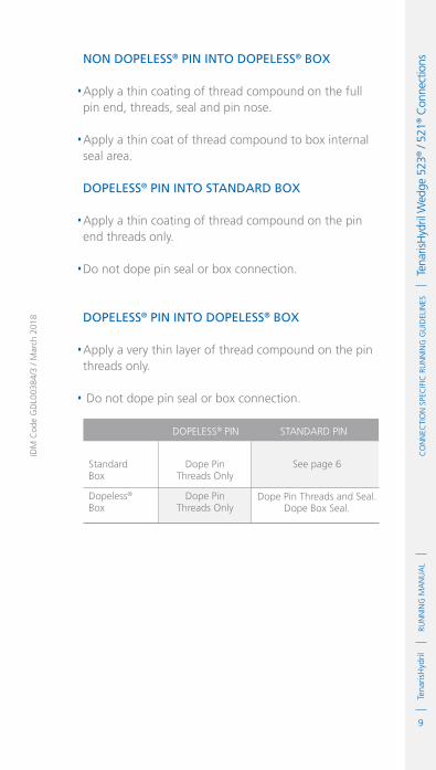
9
RUN
NIN
G M
AN
UA
LTe
naris
Hyd
ril
IDM
Cod
e G
DL0
0384
/3 /
Mar
ch 2
018
Co
NN
eCTI
oN
Spe
CIf
IC R
UN
NIN
G G
UID
eLIN
eS
Te
naris
Hyd
ril W
edge
523
® /
521®
Con
nect
ionsnon dopeleSS® pin into dopeleSS® Box
.Apply a thin coating of thread compound on the full pin end, threads, seal and pin nose.
.Apply a thin coat of thread compound to box internal seal area. dopeleSS® pin into Standard Box
.Apply a thin coating of thread compound on the pin end threads only.
.Do not dope pin seal or box connection.
dopeleSS® pin into dopeleSS® Box
.Apply a very thin layer of thread compound on the pin threads only.
. Do not dope pin seal or box connection.
StandardBox
Dopeless®
Box
See page 6
Dope Pin Threads and Seal. Dope Box Seal.
STANDARD PIN
Dope Pin Threads Only
Dope PinThreads Only
DOPELESS® PIN

10
RUN
NIN
G M
AN
UA
LTe
naris
Hyd
rilC
oN
NeC
TIo
N S
peC
IfIC
RU
NN
ING
GU
IdeL
INeS
Tena
risH
ydril
Wed
ge 5
23® /
521®
Con
nect
ions Wedge 523® / 521® Dopeless®
Thread Lock
1. Ideally when running a Dopeless® string the connections to be thread locked should be the non Dopeless® variant with the connections cleaned of thread compound and completely dried, then thread lock and dope applied as per page 7.
2. When thread locking Dopeless® connections remove the Dopeless® coating from the threads on the pin connection where the thread lock is to be applied prior to the application of thread lock.
3. Leave the Dopeless® coating on the pin seal and threads where no thread lock is to be applied.
4. Dopeless® boxes should be washed with hot water then dried prior to thread locking.
5. Thread lock should be applied to 50% of the pin threads furthest from the pin nose as per the diagram on page 7.
6. The application of thread compound is not required.
7. Do not apply thread lock to the seal area.
Torque Application
1. Set tong dump valve at optimum torque then test on pipe body.
2. For Dopeless® connections apply the specified torques as indicated on the TenarisHydril Dopeless® data sheet.
3. For doped connections, apply the specified torques indicated on the TenarisHydril standard variant data sheet.

11
RUN
NIN
G M
AN
UA
LTe
naris
Hyd
ril
IDM
Cod
e G
DL0
0384
/3 /
Mar
ch 2
018
Co
NN
eCTI
oN
Spe
CIf
IC R
UN
NIN
G G
UID
eLIN
eS
Te
naris
Hyd
ril W
edge
523
® /
521®
Con
nect
ions4. Do not apply thread compound manufacturer’s
friction factor.
5. Standard doped variant, first connection make up;
.Once optimum torque has been attained relax the tong and re-apply optimum torque.
.If movement over ½” is witnessed re-apply optimum torque +20%.
.Repeat process, checking to ensure no other factors are absorbing the applied torque.
.Often the issue is caused by excessive application of thread compound.
.Continue making up further joints applying higher torque if required.
.Refer to the TenarisHydril Running Manual torque application section.
6. Double bump, (as above) every connection with an OD of 10 ¾” or larger.
7. For Dopeless® connections applying optimum torque twice (double bump) is not necessary.
8. When any doped variant is made up to a Dopeless® connection apply the doped variant torque values. Double bump the connection as point 5.
9. When applying thread lock to standard doped connections, doped version torque values +20% should be used then double bump the connection.
10. When applying thread lock to Dopeless® connections, Dopeless® torque values +20% should be used then double bump the connection.

12
RUN
NIN
G M
AN
UA
LTe
naris
Hyd
rilC
oN
NeC
TIo
N S
peC
IfIC
RU
NN
ING
GU
IdeL
INeS
Tena
risH
ydril
Wed
ge 5
23® /
521®
Con
nect
ions 11. Computer make up equipment is not mandatory
for Wedge 523® / 521® connections in carbon steel, but is recommended.
12. Computer make up equipment is strongly recommended for Wedge 523® / 521® connections in chrome steel.
13. Graph analysis for Wedge 523® / 521® connections is similar to that for all Wedge Series 500™, refer to the TenarisHydril Running Manual make up acceptance section for further explanation.
14. When computer equipment is used to monitor connection make up, the graph profiles should be similar to the ones below.
TOR
QU
E *
1000
ft-
lbs
MAX. 6800
OPT 4800
0 0.20 0.40 0.60 0.80
TURNS
MIN. 4000
0
1.3
2.6
3.8
5.1

13
RUN
NIN
G M
AN
UA
LTe
naris
Hyd
ril
IDM
Cod
e G
DL0
0384
/3 /
Mar
ch 2
018
Co
NN
eCTI
oN
Spe
CIf
IC R
UN
NIN
G G
UID
eLIN
eS
Te
naris
Hyd
ril W
edge
523
® /
521®
Con
nect
ions
15. Wedge 523® connection has limited same size / weight interchange capability, if mixing weight / grade ensure compatibility of design and apply the higher torque value of the two connections.
16. Wedge 521® connection has limited same size / weight interchange capability, if mixing weight / grade ensure compatibility of design and apply the higher torque value of the two connections.
17. Wedge 521® and Wedge 523® connections are not interchangeable.
18. Wedge 523® and 513® connections are compatible in the same size / weight combination. For other weight combinations check the TenarisHydril premium connections catalogue.
19. When correctly assembled, Wedge 521® connection box face should finish within the make up band lines.
TOR
QU
E *
1000
ft-
lbs
MAX. 6800
OPT 4800
0
0
1.3
2.6
3.8
5.1
0.20 0.40 0.60 0.80
TURNS
MIN. 4000

14
RUN
NIN
G M
AN
UA
LTe
naris
Hyd
rilC
oN
NeC
TIo
N S
peC
IfIC
RU
NN
ING
GU
IdeL
INeS
Tena
risH
ydril
Wed
ge 5
23® /
521®
Con
nect
ions
Running 1. The use of a stabbing guide is strongly recommended.
2. The use of slip type elevators are recommended.
3. The use of a safety clamp is strongly recommended when running Wedge 523® / 521® connections.
4. The use of a weight compensator is strongly recommended for chrome, large OD or heavy weight pipe.
5. To avoid cross threading, stab pipe in a smooth controlled fashion ensuring the pipe is vertical when doing so, continue to support and stabilise the pipe throughout the make up operation.
6. Upon commencement of initial rotation use low RPM (5 RPM or below) in order to ensure the pipe has not cross threaded during stabbing.
7. If cross threading is evident, immediately reverse rotate the pipe, completely disassemble, clean and inspect both connections.
8. Apply power tong at low RPM (do not exceed 5 RPM), for final make up.
Wedge 521® Make Up Band

15
RUN
NIN
G M
AN
UA
LTe
naris
Hyd
ril
IDM
Cod
e G
DL0
0384
/3 /
Mar
ch 2
018
Co
NN
eCTI
oN
Spe
CIf
IC R
UN
NIN
G G
UID
eLIN
eS
Te
naris
Hyd
ril W
edge
523
® /
521®
Con
nect
ions9. Do not exceed 15 RPM during spin in.
10. Walk chrome pipe all the way in to hand tight, then apply tong only for final make up.
11. Ensure the back up tong is located below the box upset to prevent damage.
12. A factor which may preclude complete assembly is excessive thread compound applied to the connection, reduce the quantity applied if this is found to be the case.
Pulling 1. The use of a stabbing guide is strongly recommended to prevent hang up.
2. The use of slip type elevators is strongly recommended.
3. A single joint compensator is strongly recommended for chrome, large OD or heavy pipe.
4. The use of a safety clamp is strongly recommended.
5. Apply the back up tong jaw well below the box.
6. Apply power tong in low RPM (3-5 RPM) to break out the connection, ensuring the pipe is stabilised during the break out process.
7. Do not exceed 15 RPM during spin out.
8. Walk chrome pipe all the way out by hand after initial break out.

16
RUN
NIN
G M
AN
UA
LTe
naris
Hyd
rilC
oN
NeC
TIo
N S
peC
IfIC
RU
NN
ING
GU
IdeL
INeS
Tena
risH
ydril
Wed
ge 5
23® /
521®
Con
nect
ions 9. Visual inspection is recommended to classify the
thread condition, any rejected connections should be clearly marked and segregated for further investigation.
10. Apply clean, dry thread protectors after applying storage compound on clean, dry connections.
11. Storage / thread compound should always be applied to connections post job, even rejects.
12. Do not apply storage compound to Dopeless® connections.
13. For long term storage of Dopeless® connections, refurbishment by qualified personnel is recommended.
14. Ensure clean, dry, Dopeless® protectors with seal rings correctly in place are installed.

1
RUN
NIN
G M
AN
UA
LTe
naris
Hyd
rilC
oN
NeC
TIo
N S
peC
IfIC
RU
NN
ING
GU
IdeL
INeS
Tena
risH
ydril
Wed
ge 5
13® /
511®
Con
nect
ions
IdM
Cod
e G
dL0
0383
/3 /
Mar
ch 2
018
TenarisHydril Wedge 513® / 511® Connections
Scope
These guidelines apply specifically to the use of TenarisHydril Wedge 513® and Wedge 511® connections. This document should be used in conjunction with the TenarisHydril Running Manual which is the main document applicable for running all TenarisHydril premium connections.
References
.TenarisHydril Running Manual..Premium Connection Approved Thread Compounds TSH-MD-00.0002..Recommended guidelines for the field inspection of TenarisHydril connections, FSOG 13-005..Wedge 513® Handling Plugs TN 9906..Wedge 511® Handling Plugs TN 9710.
Equipment, Material & Documents
1. Verify the appropriate thread compound is available.
2. Refer to document TSH-MD-00.0002 for a list of compounds approved by Tenaris.

2
RUN
NIN
G M
AN
UA
LTe
naris
Hyd
rilC
oN
NeC
TIo
N S
peC
IfIC
RU
NN
ING
GU
IdeL
INeS
Tena
risH
ydril
Wed
ge 5
13® /
511®
Con
nect
ions 3. Latest version of the specific Product Data Sheet can
be obtained from the Tenaris website. In case this is unavailable, request the data sheet from the local Technical Sales representative or [email protected].
Pre-Running
1. Never move or handle pipe without the correct thread protectors securely in place.
2. Ensure connections are clean and free of all debris and / or contaminants, cleaning methods employed should conform to the recommendations contained within the TenarisHydril Running Manual.
3. Verify the connections to be assembled are genuine TenarisHydril manufactured connections.
4. Visually inspect threads and seal areas prior to running, ensuring no damage is evident.
5. On Dopeless® connections check condition of both pin and box coating ensuring no peel off or degradation has occurred.
6. Verify compatibility of the 513® / 511® connection with any accessories such as pup joints, cross overs, cement heads etc.
7. Verify material grade of all accessories ensuring compatibility with main string.
8. Check availability of handling plugs, minimum of 3 to ensure efficiency of running process.
9. Check the handling plugs are in good condition and fit correctly onto pipe.

3
RUN
NIN
G M
AN
UA
LTe
naris
Hyd
ril
IDM
Cod
e G
DL0
0383
/3 /
Mar
ch 2
018
Co
NN
eCTI
oN
Spe
CIf
IC R
UN
NIN
G G
UID
eLIN
eS
Te
naris
Hyd
ril W
edge
513
® /
511®
Con
nect
ions10. Check the handling plugs are genuine TenarisHydril
threads.
11. Verify handling plug number and maximum lift capacity.
12. Never exceed the maximum lift capacity.
13. Ensure handling plug OD / weight is compatible with the pipe connections, Wedge 513® / 511® have limited same OD / weight interchange capability.
14. Refer to the TenarisHydril running manual for the care and use of handling / lift plugs.
Inspection
1. Inspection criteria for all Wedge Series 500™ connections is as outlined in the Field Service Operative Guideline FSOG 13-005.
2. Pay particular attention to seal areas of Wedge 513®.
3. Check box and pin for signs of mashes or deformation caused during transportation / handling.
4. Ensure there are no gouges, tears or raised material on seal saver area of Wedge 513®.

4
RUN
NIN
G M
AN
UA
LTe
naris
Hyd
rilC
oN
NeC
TIo
N S
peC
IfIC
RU
NN
ING
GU
IdeL
INeS
Tena
risH
ydril
Wed
ge 5
13® /
511®
Con
nect
ions Wedge 513® Configuration
Machined
cylindrical
area
Seal
Seal Saver
Seal

5
RUN
NIN
G M
AN
UA
LTe
naris
Hyd
ril
IDM
Cod
e G
DL0
0383
/3 /
Mar
ch 2
018
Co
NN
eCTI
oN
Spe
CIf
IC R
UN
NIN
G G
UID
eLIN
eS
Te
naris
Hyd
ril W
edge
513
® /
511®
Con
nect
ionsWedge 511® Configuration
No metal to metal seal on Wedge 511®.
Machined
cylindrical
area

6
RUN
NIN
G M
AN
UA
LTe
naris
Hyd
rilC
oN
NeC
TIo
N S
peC
IfIC
RU
NN
ING
GU
IdeL
INeS
Tena
risH
ydril
Wed
ge 5
13® /
511®
Con
nect
ions Thread Compound Application
For carbon Steel pipe
1. Apply a thin coating of thread compound on the full pin end only, threads, seal and pin nose, the thread form should be clearly visible.
2. Do not apply running compound to the box end.
3. Thread compound should be cleaned from the box of carbon steel if received ‘rig ready’.
For chroMe Material pipe
1. Apply a thin coating of thread compound on both pin and box ensuring all threads, seal and pin nose are completely covered.
2. Do not over dope the connections, a thin even layer covering all surfaces is adequate.
carbon Steel
chroMe Material

7
RUN
NIN
G M
AN
UA
LTe
naris
Hyd
ril
IDM
Cod
e G
DL0
0383
/3 /
Mar
ch 2
018
Co
NN
eCTI
oN
Spe
CIf
IC R
UN
NIN
G G
UID
eLIN
eS
Te
naris
Hyd
ril W
edge
513
® /
511®
Con
nect
ionsThread Lock Application
Connections must be clean and dry when applying thread lock.
1. Thread lock should be applied to 50% of the threads at the back of the pin connection.
2. Running compound should then be applied to the threads and seal at the back of the box connection.
3. When assembling standard non Dopeless® connections with thread lock use standard non Dopeless® torque values.

8
RUN
NIN
G M
AN
UA
LTe
naris
Hyd
rilC
oN
NeC
TIo
N S
peC
IfIC
RU
NN
ING
GU
IdeL
INeS
Tena
risH
ydril
Wed
ge 5
13® /
511®
Con
nect
ions Wedge 513® / 511® Dopeless®
1. Minor rust or discolouring of the pin connection can be removed with the use of a clean, dry rag ensuring the Dopeless® coating remains intact.
2. Minor rust or discolouring of the box connection can be removed with the use of a non abrasive plastic scouring pad and a clean, dry rag ensuring the Dopeless® coating remains intact.
3. Dopeless® connections do not require the application of thread compound for make up.
4. If for whatever reason dope has to be applied to Dopeless® connections, whether both pin and box are Dopeless® or when mixing a standard connection with Dopeless®, apply thread compound as below:

9
RUN
NIN
G M
AN
UA
LTe
naris
Hyd
ril
IDM
Cod
e G
DL0
0383
/3 /
Mar
ch 2
018
Co
NN
eCTI
oN
Spe
CIf
IC R
UN
NIN
G G
UID
eLIN
eS
Te
naris
Hyd
ril W
edge
513
® /
511®
Con
nect
ionsnon dopeleSS® pin into dopeleSS® box
.Apply a thin coating of thread compound on the full pin end, threads, seal and pin nose.
.Apply a thin coat of thread compound to box internal seal area. dopeleSS® pin into Standard box
.Apply a thin coating of thread compound on the pin end threads only.
.Do not dope pin seal or box connection.
dopeleSS® pin into dopeleSS® box
.Apply a very thin layer of thread compound on the pin threads only.
.Do not dope pin seal or box connection.
StandardBox
Dopeless®
Box
See page 6
Dope Pin Threads & Seal. Dope Box Seal.
STANDARD PIN
Dope Pin Threads Only
Dope PinThreads Only
DOPELESS® PIN

10
RUN
NIN
G M
AN
UA
LTe
naris
Hyd
rilC
oN
NeC
TIo
N S
peC
IfIC
RU
NN
ING
GU
IdeL
INeS
Tena
risH
ydril
Wed
ge 5
13® /
511®
Con
nect
ions Wedge 513® / 511® Dopeless®
Thread Lock
1. Ideally when running a Dopeless® string the connections to be thread locked should be the non Dopeless® variant with the connections cleaned of thread compound and completely dried, then thread lock and dope applied as per page 7.
2. When thread locking Dopeless® connections remove the Dopeless® coating from the threads on the pin connection where the thread lock is to be applied prior to the application of thread lock.
3. Leave the Dopeless® coating on the pin seal and threads where no thread lock is to be applied.
4. Dopeless® boxes should be washed with hot water then dried prior to thread locking.
5. Thread lock should be applied to 50% of the pin threads furthest from the pin nose, as per the diagram on page 7.
6. The application of thread compound is not required.
7. Do not apply thread lock to the seal area.
Torque Application
1. Set tong dump valve at optimum torque then test on pipe body.
2. For Dopeless® connections apply the specified torques as indicated on the TenarisHydril Dopeless® data sheet.

11
RUN
NIN
G M
AN
UA
LTe
naris
Hyd
ril
IDM
Cod
e G
DL0
0383
/3 /
Mar
ch 2
018
Co
NN
eCTI
oN
Spe
CIf
IC R
UN
NIN
G G
UID
eLIN
eS
Te
naris
Hyd
ril W
edge
513
® /
511®
Con
nect
ions3. For doped connections, apply the specified
torques indicated on the TenarisHydril standard variant data sheet.
4. Do not apply thread compound manufacturer’s friction factor.
5. Standard doped variant, first connection make up;
.Once optimum torque has been attained relax the tong and re-apply optimum torque.
.If movement over ½" is witnessed re-apply optimum torque +20%.
.Repeat process, checking to ensure no other factors are absorbing the applied torque.
.Often the issue is caused by excessive application of thread compound.
.Continue making up further joints applying higher torque if required.
.Refer to the TenarisHydril Running Manual torque application section.
6. Double bump, (as above) every connection with an OD of 10 ¾" or larger.
7. For Dopeless® connections applying optimum torque twice (double bump) is not necessary.
8. When applying thread lock to standard doped connections, doped version torque values +20% should be used then double bump the connection.
9. When applying thread lock to Dopeless® connections, Dopeless® torque values +20% should be used then double bump the connection.

12
RUN
NIN
G M
AN
UA
LTe
naris
Hyd
rilC
oN
NeC
TIo
N S
peC
IfIC
RU
NN
ING
GU
IdeL
INeS
Tena
risH
ydril
Wed
ge 5
13® /
511®
Con
nect
ions 10. When any doped variant is made up to a Dopeless®
connection apply the doped variant torque values. Double bump the connection as point 5.
11. When applying thread lock, doped version torque values +20% should be used, double bump the connection.
12. Computer make up equipment is not mandatory for Wedge 513® / 511® connections in carbon steel, but is recommended.
13. Computer make up equipment is strongly recommended for Wedge 513® / 511® connections in chrome steel.
14. Graph analysis for Wedge 513® / 511® connections is similar to that for all Wedge Series 500™, refer to the TenarisHydril Running Manual make up acceptance section for further explanation.
15. When computer equipment is used to monitor connection make up, the graph profiles should be similar to the ones below.
TOR
QU
E *
1000
ft-
lbs
MAX. 6800
OPT 4800
0 0.20 0.40 0.60 0.80
TURNS
MIN. 4000
0
1.3
2.6
3.8
5.1

13
RUN
NIN
G M
AN
UA
LTe
naris
Hyd
ril
IDM
Cod
e G
DL0
0383
/3 /
Mar
ch 2
018
Co
NN
eCTI
oN
Spe
CIf
IC R
UN
NIN
G G
UID
eLIN
eS
Te
naris
Hyd
ril W
edge
513
® /
511®
Con
nect
ions
16. Wedge 513® connection has limited same size / weight interchange capability, if mixing weight / grade ensure compatibility of design and apply the higher torque value of the two connections.
17. Wedge 511® connection has limited same size / weight interchange capability, if mixing weight / grade ensure compatibility of design and apply the higher torque value of the two connections.
18. Wedge 513® and 511® connections are not interchangeable.
19. Wedge 513® and 523® connections are compatible in the same size / weight combination. For other weight combinations check the TenarisHydril premium connections catalogue.
TOR
QU
E *
1000
ft-
lbs
MAX. 6800
OPT 4800
0
0
1.3
2.6
3.8
5.1
0.20 0.40 0.60 0.80
TURNS
MIN. 4000

14
RUN
NIN
G M
AN
UA
LTe
naris
Hyd
rilC
oN
NeC
TIo
N S
peC
IfIC
RU
NN
ING
GU
IdeL
INeS
Tena
risH
ydril
Wed
ge 5
13® /
511®
Con
nect
ions Running
1. The use of a stabbing guide is strongly recommended.
2. The use of slip type elevators is strongly recommended.
3. The use of a safety clamp is strongly recommended when running Wedge 513® / 511® connections.
4. The use of a weight compensator is strongly recommended for chrome, large OD or heavy weight pipe.
5. To avoid cross threading, stab pipe in a smooth controlled fashion ensuring the pipe is vertical when doing so, continue to support and stabilise the pipe throughout the make up operation.
6. Upon commencement of initial rotation use low RPM (5 RPM or below) in order to ensure the pipe has not cross threaded during stabbing.
7. If cross threading is evident, immediately reverse rotate the pipe, completely disassemble, clean and inspect both connections.
8. Do not exceed 15 RPM during spin in.
9. Apply power tong at low RPM (do not exceed 5 RPM), for final make up.
10. Walk chrome pipe all the way in to hand tight, then apply tong only for final make up.
11. Ensure the back up tong is located below the box upset to prevent damage.
12. A factor which may preclude complete assembly is excessive thread compound applied to the connection, reduce the quantity applied if this is found to be the case.

15
RUN
NIN
G M
AN
UA
LTe
naris
Hyd
ril
IDM
Cod
e G
DL0
0383
/3 /
Mar
ch 2
018
Co
NN
eCTI
oN
Spe
CIf
IC R
UN
NIN
G G
UID
eLIN
eS
Te
naris
Hyd
ril W
edge
513
® /
511®
Con
nect
ionsPulling
1. The use of a stabbing guide is strongly recommended to prevent hang up.
2. The use of a safety clamp is strongly recommended.
3. A single joint compensator is strongly recommended for chrome, large OD or heavy pipe.
4. Apply the back up tong jaw well below the box.
5. Apply power tong in low rpm (3-5 RPM) to break out the connection, ensuring the pipe is stabilised during the break and spin out process.
6. Do not exceed 15 RPM during spin out.
7. Walk chrome pipe all the way out by hand after initial break out.
8. Visual inspection is recommended to classify the thread condition, any rejected connections should be clearly marked and segregated for further investigation.
9. Apply clean, dry thread protectors after applying storage compound on clean, dry connections.
10. Storage / thread compound should always be applied to connections post job, even rejects.
11. Do not apply storage compound to Dopeless® connections.
12. For long term storage of Dopeless® connections, refurbishment by qualified personnel is recommended.
13. Ensure clean, dry, Dopeless® protectors with seal rings correctly in place are installed.

16
RUN
NIN
G M
AN
UA
LTe
naris
Hyd
rilC
oN
NeC
TIo
N S
peC
IfIC
RU
NN
ING
GU
IdeL
INeS
Tena
risH
ydril
Wed
ge 5
13® /
511®
Con
nect
ions

1
RUN
NIN
G M
AN
UA
LTe
naris
Hyd
rilC
oN
NeC
TIo
N S
peC
IfIC
RU
NN
ING
GU
IdeL
INeS
Tena
risH
ydril
Wed
ge 5
63® C
onne
ctio
n
IdM
Cod
e G
dL2
3533
/1 /
Mar
ch 2
018
TenarisHydril Wedge 563® ConnectionScope
These guidelines apply specifically to the use of TenarisHydril Wedge 563® connections. This document should be used in conjunction with the TenarisHydril Running Manual, which is the main document applicable for running all TenarisHydril premium connections.
References
.TenarisHydril Running Manual..Premium Connection Approved Thread Compounds TSH-MD-00.0002..Recommended guidelines for the field inspection of TenrisHydril connections, FSOG 13-005.
Equipment, Material & Documents
1. Verify the appropriate thread compound is available.
2. Refer to document TSH-MD-00.0002 for a list of compounds approved by Tenaris.
3. Latest version of the specific Product Data Sheet can be obtained from Tenaris website. In case this is not available, request the data sheet from the local Technical Sales representative or [email protected].

2
RUN
NIN
G M
AN
UA
LTe
naris
Hyd
rilC
oN
NeC
TIo
N S
peC
IfIC
RU
NN
ING
GU
IdeL
INeS
Tena
risH
ydril
Wed
ge 5
63® C
onne
ctio
n Pre-Running
1. Never move or handle pipe without the correct thread protectors securely in place.
2. Ensure connections are clean and free of all debris and / or contaminants, cleaning methods employed should conform to the recommendations contained within the TenarisHydril Running Manual.
3. Verify all pipe and accessories have genuine TenarisHydril manufactured connections.
4. Visually inspect thread and seal areas prior to running, ensuring no damage is evident.
5. On Dopeless® connections, check condition of both pin and box coating ensuring no peel off or degradation has occurred.
6. Verify the compatibility of the Wedge 563® connection with accessories such as cement heads, safety valves, cross overs, etc.
7. Verify material grade of all accessories ensuring compatibility with main string.

3
RUN
NIN
G M
AN
UA
LTe
naris
Hyd
ril
IDM
Cod
e G
DL2
3533
/1 /
Mar
ch 2
018
Co
NN
eCTI
oN
Spe
CIf
IC R
UN
NIN
G G
UID
eLIN
eS
Te
naris
Hyd
ril W
edge
563
® C
onne
ctio
nInspection
1. Inspection criteria for all Wedge Series 500™ connections is as outlined in the Field Service Operative Guideline FSOG 13-005.
2. Pay particular attention to seal areas.
3. Ensure the pin nose has no raised metal.
4. For CB® variant ensure seal ring groove is clear of debris or damage which may preclude correct installation of the CB® ring.

4
RUN
NIN
G M
AN
UA
LTe
naris
Hyd
rilC
oN
NeC
TIo
N S
peC
IfIC
RU
NN
ING
GU
IdeL
INeS
Tena
risH
ydril
Wed
ge 5
63® C
onne
ctio
n Wedge 563® Casing Configuration
Seal
aSSembly make
up band
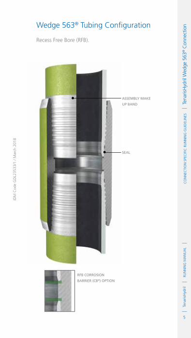
5
RUN
NIN
G M
AN
UA
LTe
naris
Hyd
ril
IDM
Cod
e G
DL2
3533
/1 /
Mar
ch 2
018
Co
NN
eCTI
oN
Spe
CIf
IC R
UN
NIN
G G
UID
eLIN
eS
Te
naris
Hyd
ril W
edge
563
® C
onne
ctio
nWedge 563® Tubing Configuration
Recess Free Bore (RFB).
RFb CoRRoSion
baRRieR (Cb®) option
Seal
aSSembly make
up band

6
RUN
NIN
G M
AN
UA
LTe
naris
Hyd
rilC
oN
NeC
TIo
N S
peC
IfIC
RU
NN
ING
GU
IdeL
INeS
Tena
risH
ydril
Wed
ge 5
63® C
onne
ctio
n Thread Compound Application
FoR CaRbon Steel pipe
1. Apply a thin coating of thread compound on the full pin end only, threads, seal and pin nose, the thread form should be clearly visible.
2. Do not apply running compound to the box end.
3. Thread compound should be cleaned from the box of carbon steel if received ‘rig ready’.
FoR ChRome mateRial pipe
1. Apply a thin coating of thread compound on both pin and box ensuring all threads, seal and pin nose are completely covered. The thread form should be clearly visible.
2. Do not over dope the connections, a thin even layer covering all surfaces is adequate.
CaRbon Steel
ChRome mateRial

7
RUN
NIN
G M
AN
UA
LTe
naris
Hyd
ril
IDM
Cod
e G
DL2
3533
/1 /
Mar
ch 2
018
Co
NN
eCTI
oN
Spe
CIf
IC R
UN
NIN
G G
UID
eLIN
eS
Te
naris
Hyd
ril W
edge
563
® C
onne
ctio
nThread Lock Application
Connections must be clean and dry when applying thread lock.
1. Thread lock should be applied to 50% of the threads at the back of the pin connection.
2. Running compound should then be applied to the threads and seal at the back of the box connection.
3. When assembling standard non Dopeless® connections with thread lock use standard non Dopeless® torque values +20%.

8
RUN
NIN
G M
AN
UA
LTe
naris
Hyd
rilC
oN
NeC
TIo
N S
peC
IfIC
RU
NN
ING
GU
IdeL
INeS
Tena
risH
ydril
Wed
ge 5
63® C
onne
ctio
n
Wedge 563® Dopeless®
1. Minor rust or discolouring of the pin connection can be removed with the use of a clean dry rag ensuring the Dopeless® coating remains intact.
2. Minor rust or discolouring of the box connection can be removed with the use of a non abrasive plastic scouring pad and a clean dry rag ensuring the Dopeless® coating remains intact.
3. Dopeless® connections do not require the application of thread compound for make up.
4. If for whatever reason dope has to be applied to Dopeless® connections, whether both pin and box are Dopeless® or when mixing a standard connection with Dopeless®, apply thread compound as below:

9
RUN
NIN
G M
AN
UA
LTe
naris
Hyd
ril
IDM
Cod
e G
DL2
3533
/1 /
Mar
ch 2
018
Co
NN
eCTI
oN
Spe
CIf
IC R
UN
NIN
G G
UID
eLIN
eS
Te
naris
Hyd
ril W
edge
563
® C
onne
ctio
nnon dopeleSS® pin into dopeleSS® box
.Apply a thin coating of thread compound on the full pin end, threads, seal and pin nose.
.Apply a thin coat of thread compound to box seal area. dopeleSS® pin into StandaRd box
.Apply a thin coating of thread compound on the pin end threads only.
.Do not dope pin seal or box connection.
dopeleSS® pin into dopeleSS® box
.Apply a very thin layer of thread compound on the pin threads only.
.Do not dope pin seal or box connection.
StandardBox
Dopeless®
Box
See page 6
Dope Pin Threads & Seal. Dope Box Seal.
STANDARD PIN
Dope Pin Threads Only
Dope PinThreads Only
DOPELESS® PIN
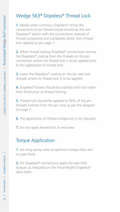
10
RUN
NIN
G M
AN
UA
LTe
naris
Hyd
rilC
oN
NeC
TIo
N S
peC
IfIC
RU
NN
ING
GU
IdeL
INeS
Tena
risH
ydril
Wed
ge 5
63® C
onne
ctio
n Wedge 563® Dopeless® Thread Lock
1. Ideally when running a Dopeless® string the connections to be thread locked should be the non Dopeless® option with the connections cleaned of thread compound and completely dried, then thread lock applied as per page 7.
2. When thread locking Dopeless® connections remove the Dopeless® coating from the threads on the pin connection where the thread lock is to be applied prior to the application of thread lock.
3. Leave the Dopeless® coating on the pin seal and threads where no thread lock is to be applied.
4. Dopeless® boxes should be washed with hot water then dried prior to thread locking.
5. Thread lock should be applied to 50% of the pin threads furthest from the pin nose as per the diagram on page 7.
6. The application of thread compound is not required.
7. Do not apply thread lock to seal area.
Torque Application
1. Set tong dump valve at optimum torque then test on pipe body.
2. For Dopeless® connections apply the specified torques as indicated on the TenarisHydril Dopeless® data sheet.

11
RUN
NIN
G M
AN
UA
LTe
naris
Hyd
ril
IDM
Cod
e G
DL2
3533
/1 /
Mar
ch 2
018
Co
NN
eCTI
oN
Spe
CIf
IC R
UN
NIN
G G
UID
eLIN
eS
Te
naris
Hyd
ril W
edge
563
® C
onne
ctio
n3. For doped connections, apply the specified torques indicated on the TenarisHydril standard variant data sheet.
4. Do not apply thread compound manufacturer’s friction factor.
5. Standard ‘Doped’ variant, first connection make up;
.Once optimum torque has been attained relax the tong and re-apply optimum torque.
. If movement over ½” is witnessed re-apply optimum torque +20%.
.Repeat process, checking to ensure no other factors are absorbing the applied torque.
.Often the issue is caused by excessive application of thread compound.
.Continue making up further joints applying higher torque if required.
.Refer to the TenarisHydril Running Manual torque application section.
6. Double bump (as above) every connection with an OD of 10 ¾” or larger.
7. For Dopeless® connections, applying optimum torque twice (double bump) is not necessary.
8. When applying thread lock to standard doped connections, doped version torque values +20% should be used then double bump the connection.
9. When applying thread lock to Dopeless® connections, Dopeless® torque values +20% should be used then double bump the connection.

12
RUN
NIN
G M
AN
UA
LTe
naris
Hyd
rilC
oN
NeC
TIo
N S
peC
IfIC
RU
NN
ING
GU
IdeL
INeS
Tena
risH
ydril
Wed
ge 5
63® C
onne
ctio
n 10. When any doped variant is made up to a Dopeless® connection apply the doped variant torque values. Double bump the connection as point 5.
11. Wedge 563® has limited same size / weight interchange capability, if mixing weight / grade ensure compatibility of design and apply the higher torque value of the two connections.
12. Wedge 563® is compatible with Wedge 563®-CB® variant in the same size / weight, apply standard optimum torque.
13. Computer make up equipment is not mandatory for Wedge 563® connections in carbon steel, but is recommended.
14. Computer make up equipment is strongly recommended for Wedge 563® connections in chrome steel.
15. Graph analysis for Wedge 563® is similar to that for all Wedge Series 500™, refer to the TenarisHydril running manual make up acceptance section for further explanation.
16. When computer equipment is used to monitor connection make up, the graph profiles should be similar to the ones below.
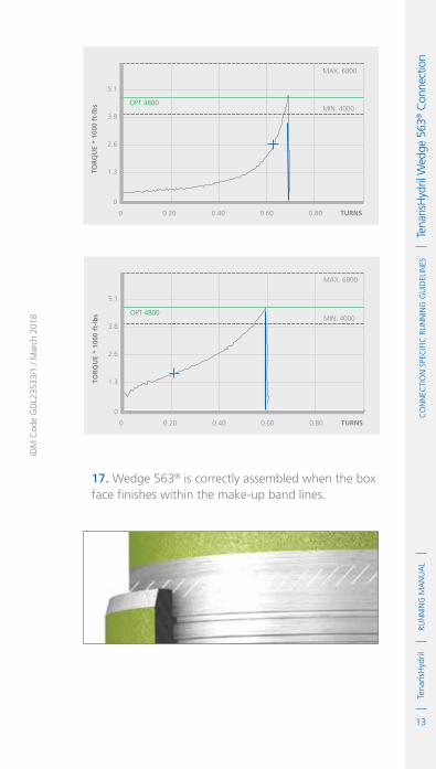
13
RUN
NIN
G M
AN
UA
LTe
naris
Hyd
ril
IDM
Cod
e G
DL2
3533
/1 /
Mar
ch 2
018
Co
NN
eCTI
oN
Spe
CIf
IC R
UN
NIN
G G
UID
eLIN
eS
Te
naris
Hyd
ril W
edge
563
® C
onne
ctio
n
TOR
QU
E *
1000
ft-
lbs
MAX. 6800
OPT 4800
0 0.20 0.40 0.60 0.80
TURNS
MIN. 4000
0
1.3
2.6
3.8
5.1TO
RQ
UE
* 10
00 f
t-lb
s
MAX. 6800
OPT 4800
0
0
1.3
2.6
3.8
5.1
0.20 0.40 0.60 0.80
TURNS
MIN. 4000
17. Wedge 563® is correctly assembled when the box face finishes within the make-up band lines.

14
RUN
NIN
G M
AN
UA
LTe
naris
Hyd
rilC
oN
NeC
TIo
N S
peC
IfIC
RU
NN
ING
GU
IdeL
INeS
Tena
risH
ydril
Wed
ge 5
63® C
onne
ctio
n Running 1. The use of a stabbing guide is strongly recommended.
2. The use of slip type elevators is strongly recommended.
3. The use of a weight compensator is strongly recommended for chrome, large OD or heavy weight pipe.
4. For CB® variant a new CB® ring should be installed prior to every make up.
5. To avoid cross threading stab pipe in a smooth controlled fashion ensuring the pipe is vertical when doing so, continue to support and stabilise the pipe throughout the make up operation.
6. Upon commencement of initial rotation use low RPM (5 RPM or below) in order to ensure the pipe has not cross threaded during stabbing.
7. If cross threading is evident, immediately reverse rotate the pipe, completely disassemble, clean and inspect both connections.
8. Maximum spin in speed should not exceed 15 RPM.
9. Apply power tong at low RPM (do not exceed 5 RPM) for final make up.
10. Walk chrome pipe all the way in to hand tight, then apply tong only for final make up.
11. Never apply back up tong over the coupling.
12. A factor which may preclude complete assembly is excessive thread compound applied to the connection, reduce the quantity applied if this is found to be the case.

15
RUN
NIN
G M
AN
UA
LTe
naris
Hyd
ril
IDM
Cod
e G
DL2
3533
/1 /
Mar
ch 2
018
Co
NN
eCTI
oN
Spe
CIf
IC R
UN
NIN
G G
UID
eLIN
eS
Te
naris
Hyd
ril W
edge
563
® C
onne
ctio
nPulling 1. The use of a stabbing guide is strongly recommended to prevent hang up.
2. A single joint compensator is strongly recommended for chrome, large OD or heavy pipe.
3. Apply the back up tong on the pipe body below the coupling.
4. Apply power tong in low RPM (3-5 RPM) to break out the connection, ensuring the pipe is stabilized during the break out process.
5. Maximum spin out speed should not exceed 15 RPM.
6. Walk chrome pipe all the way out by hand after initial break out.
7. Visual inspection is recommended to classify the thread condition, any rejected connections should be clearly marked and segregated for further investigation.
8. Apply clean, dry thread protectors after applying storage compound on clean, dry connections.
9. Storage / thread compound should always be applied to connections post job, even rejects.
10. Do not apply storage compound to Dopeless® connections.
11. For long term storage of Dopeless® connections, refurbishment by qualified personnel is recommended.
12. Ensure clean, dry, Dopeless® protectors with seal rings correctly in place are installed.

16
RUN
NIN
G M
AN
UA
LTe
naris
Hyd
rilC
oN
NeC
TIo
N S
peC
IfIC
RU
NN
ING
GU
IdeL
INeS
Tena
risH
ydril
Wed
ge 5
63® C
onne
ctio
n

1
RUN
NIN
G M
AN
UA
LTe
naris
Hyd
rilC
oN
NeC
TIo
N S
peC
IfIC
RU
NN
ING
GU
IdeL
INeS
Tena
risH
ydril
Wed
ge 6
25® C
onne
ctio
n
IdM
Cod
e G
dL0
0336
/2 /
Mar
ch 2
018
TenarisHydril Wedge 625® ConnectionScope
These guidelines apply specifically to the use of TenarisHydril Wedge 625® connections. This document should be used in conjunction with the TenarisHydril Running Manual, which is the main document applicable for running all TenarisHydril premium connections.
References
.TenarisHydril Running Manual..Premium Connection Approved Thread Compounds TSH-MD-00.0002..Recommended guidelines for the field inspection of TenarisHydril connections, FSOG 13-005.
Equipment, Material & Documents
1. Verify the appropriate thread compound is available for this connection.
2. Refer to document TSH-MD-00.0002 for a list of compounds approved by Tenaris.
3. Latest version of the specific Product Data Sheet can be obtained from Tenaris web site. In case it is not available, request the data sheet from the local Technical Sales representative or [email protected].

2
RUN
NIN
G M
AN
UA
LTe
naris
Hyd
rilC
oN
NeC
TIo
N S
peC
IfIC
RU
NN
ING
GU
IdeL
INeS
Tena
risH
ydril
Wed
ge 6
25® C
onne
ctio
n Pre-Running
1. Never move or handle pipe without the correct thread protectors securely in place.
2. Ensure connections are cleaned and free of all debris and / or contaminants, cleaning methods employed should conform to the recommendations contained within the TenarisHydril Running Manual.
3. Visually inspect threads and seal areas prior to running, ensuring no damage is evident.
4. Verify all pipe and accessories have genuine TenarisHydril manufactured connections.
5. Verify the compatibility of the Wedge 625® connection with accessories such as pup joints, cross overs, cement heads, etc
6. Verify material grade of all accessories ensuring compatibility with main string.
7. On Dopeless® connections check condition of both pin and box coating ensuring no peel off or degradation has occurred.
8. Check availability of handling plugs, minimum of 3 to ensure efficiency of running process.
9. Check the handling plugs are in good condition and fit correctly onto pipe.
10. Check single joint elevators have sufficient clearance to slide over box expanded area and seat against the handling plug.
11. Check the handling plugs are genuine TenarisHydril threads.

3
RUN
NIN
G M
AN
UA
LTe
naris
Hyd
ril
IDM
Cod
e G
DL0
0336
/2 /
Mar
ch 2
018
Co
NN
eCTI
oN
Spe
CIf
IC R
UN
NIN
G G
UID
eLIN
eS
Te
naris
Hyd
ril W
edge
625
® C
onne
ctio
n12. Verify handling plug number and maximum lift capacity.
13. Never exceed the maximum lift capacity.
14. Ensure handling plug OD / weight is compatible with the pipe connections, Wedge 625® has limited same OD / weight interchange capability.
15. Refer to the TenarisHydril running manual for the care and use of handling / lift plugs.
Inspection
1. Inspection criteria for all Wedge Series 600™ connections is as outlined in the Field Service Operative Guideline FSOG 13-005.
2. Pay particular attention to seal area.
3. Ensure there are no gouges, tears or raised material on the lead in areas from final thread to seal
4. Check box connections for mashes or ovality caused by transportation, handling or storage.

4
RUN
NIN
G M
AN
UA
LTe
naris
Hyd
rilC
oN
NeC
TIo
N S
peC
IfIC
RU
NN
ING
GU
IdeL
INeS
Tena
risH
ydril
Wed
ge 6
25® C
onne
ctio
n Wedge 625® Configuration
IntermedIate seal
make Up Band
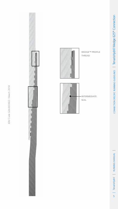
5
RUN
NIN
G M
AN
UA
LTe
naris
Hyd
ril
IDM
Cod
e G
DL0
0336
/2 /
Mar
ch 2
018
Co
NN
eCTI
oN
Spe
CIf
IC R
UN
NIN
G G
UID
eLIN
eS
Te
naris
Hyd
ril W
edge
625
® C
onne
ctio
n
Wedge™ profIle
thread
IntermedIate
seal

6
RUN
NIN
G M
AN
UA
LTe
naris
Hyd
rilC
oN
NeC
TIo
N S
peC
IfIC
RU
NN
ING
GU
IdeL
INeS
Tena
risH
ydril
Wed
ge 6
25® C
onne
ctio
n Thread Compound Application
for CarBon steel pIpe
1. Apply a thin coating of thread compound on the full pin end only, threads, seal and pin nose, the thread form should be clearly visible.
2. Do not apply running compound to the box end.
3. Thread compound should be cleaned from the box of carbon steel if received ‘rig ready’.
for Chrome materIal pIpe
1. Apply a thin coating of thread compound on both pin and box ensuring all threads, seal and pin nose are completely covered. The thread form should be clearly visible.
2. Do not over dope the connections, a thin even layer covering all surfaces is adequate, the thread form should be fully visible.
CarBon steel
Chrome materIal

7
RUN
NIN
G M
AN
UA
LTe
naris
Hyd
ril
IDM
Cod
e G
DL0
0336
/2 /
Mar
ch 2
018
Co
NN
eCTI
oN
Spe
CIf
IC R
UN
NIN
G G
UID
eLIN
eS
Te
naris
Hyd
ril W
edge
625
® C
onne
ctio
nThread Lock Application Non Dopeless® Connections
Connections must be clean and dry when applying thread lock.
1. Thread lock should be applied to 50% of the threads at the back of the pin connection.
2. Do not apply thread lock to the intermediate seal.
3. Running compound should then be applied to the threads and seal at the back of the box connection.
4. When assembling standard non Dopeless® connections with thread lock use standard non Dopeless® torque values.

8
RUN
NIN
G M
AN
UA
LTe
naris
Hyd
rilC
oN
NeC
TIo
N S
peC
IfIC
RU
NN
ING
GU
IdeL
INeS
Tena
risH
ydril
Wed
ge 6
25® C
onne
ctio
n Wedge 625® Dopeless®
1. Minor rust or discolouring of the pin connection can be removed with the use of a clean, dry rag ensuring the Dopeless® coating remains intact.
2. Minor rust or discolouring of the box connection can be removed with the use of a non abrasive plastic scouring pad and a clean, dry rag ensuring the Dopeless® coating remains intact.
3. Dopeless® connections do not require the application of thread compound for make up.
4. If for whatever reason dope has to be applied to Dopeless® connections, whether both pin and box are Dopeless® or when mixing a standard connection with Dopeless®, apply thread compound as below:

9
RUN
NIN
G M
AN
UA
LTe
naris
Hyd
ril
IDM
Cod
e G
DL0
0336
/2 /
Mar
ch 2
018
Co
NN
eCTI
oN
Spe
CIf
IC R
UN
NIN
G G
UID
eLIN
eS
Te
naris
Hyd
ril W
edge
625
® C
onne
ctio
nnon dopeless® pIn Into dopeless® Box
.Apply a thin coating of thread compound on the full pin end, threads, seal and pin nose.
.Apply a thin coat of thread compound to box internal seal area. dopeless® pIn Into standard Box
.Apply a thin coating of thread compound on the pin end threads only.
.Do not dope pin seal or box connection.
dopeless® pIn Into dopeless® Box
.Apply a very thin layer of thread compound on the pin threads only.
.Do not dope pin seal or box connection.
StandardBox
Dopeless®
Box
See page 6
Dope Pin Threads & Seal. Dope Box Seal.
STANDARD PIN
Dope Pin Threads Only
Dope PinThreads Only
DOPELESS® PIN

10
RUN
NIN
G M
AN
UA
LTe
naris
Hyd
rilC
oN
NeC
TIo
N S
peC
IfIC
RU
NN
ING
GU
IdeL
INeS
Tena
risH
ydril
Wed
ge 6
25® C
onne
ctio
n Wedge 625® Dopeless® Thread Lock
1. Ideally when running a Dopeless® string the connections to be thread locked should be the non Dopeless® variant with the connections cleaned of thread compound and completely dried, then thread lock and dope applied as per page 7.
2. When thread locking Dopeless® connections remove the Dopeless® coating from the threads on the pin connection where the thread lock is to be applied prior to the application of thread lock.
3. Leave the Dopeless® coating on the pin seal and threads where no thread lock is to be applied.
4. Dopeless® boxes should be washed with hot water then dried prior to thread locking.
5. Thread lock should be applied to 50% of the pin threads immediately behind the seal area, as per the diagram on page 7.
6. The application of thread compound is not required.
7. Do not apply thread lock to seal area.
Torque Application
1. Set tong dump valve at optimum torque then test on the pipe body.
2. For Dopeless® connections apply the specified torques as indicated on the TenarisHydril Dopeless® data sheet.
3. For doped connections, apply the specified torques indicated on the TenarisHydril standard variant data sheet.

11
RUN
NIN
G M
AN
UA
LTe
naris
Hyd
ril
IDM
Cod
e G
DL0
0336
/2 /
Mar
ch 2
018
Co
NN
eCTI
oN
Spe
CIf
IC R
UN
NIN
G G
UID
eLIN
eS
Te
naris
Hyd
ril W
edge
625
® C
onne
ctio
n4. Do not apply thread compound manufacturer’s friction factor.
5. Standard ‘Doped’ variant, first connection make up;
.Once optimum torque has been attained relax the tong and re-apply optimum torque.
.If movement over ½" is witnessed re-apply optimum torque +20%.
.Repeat process, checking to ensure no other factors are absorbing the applied torque.
.Often the issue is caused by excessive application of thread compound.
.Continue making up further joints applying higher torque if required.
.Refer to the TenarisHydril Running Manual torque application section.
6. Double bump (as above) every connection with an OD of 10 ¾" or larger.
7. For Dopeless® connections applying optimum torque twice (double bump) is not necessary.
8. When applying thread lock to standard doped connections, doped version torque values +20% should be used then double bump the connection.
9. When applying thread lock to Dopeless® connections, Dopeless® torque values + 20% should be used then double bump the connection.
10. When any doped variant is made up to a Dopeless® connection apply the doped variant torque values. Double bump the connection as point 5.

12
RUN
NIN
G M
AN
UA
LTe
naris
Hyd
rilC
oN
NeC
TIo
N S
peC
IfIC
RU
NN
ING
GU
IdeL
INeS
Tena
risH
ydril
Wed
ge 6
25® C
onne
ctio
n 11. Wedge 625® connection has limited same size/weight interchange capability, if mixing weight / grade ensure compatibility of design and apply the higher torque values of the two connections.
12. Computer make up equipment is not mandatory for Wedge 625® connections in carbon steel however it is recommended.
13. Computer make up equipment is strongly recommended for Wedge 625® connections in chrome steel.
14. Graph analysis for Wedge 625® is similar to that of Wedge Series 500™, refer to the TenarisHydril Running Manual make up acceptance section for further explanation.
15. When computer equipment is used to monitor connection make up, the graph profile should be similar to the ones below.

13
RUN
NIN
G M
AN
UA
LTe
naris
Hyd
ril
IDM
Cod
e G
DL0
0336
/2 /
Mar
ch 2
018
Co
NN
eCTI
oN
Spe
CIf
IC R
UN
NIN
G G
UID
eLIN
eS
Te
naris
Hyd
ril W
edge
625
® C
onne
ctio
n
TOR
QU
E
0
0
4
8
12
16
20
0.6 1.2 1.8 2.4 3
TURNS
OPT 17,300 ft.lbs
MAX. 21,000 ft.lbs
MIN. 14,400 ft.lbs
TOR
QU
E
0
0
4
8
12
16
20
0.6 1.2 1.8 2.4 3
TURNS
OPT 17,300 ft.lbs
MAX. 21,000 ft.lbs
MIN. 14,400 ft.lbs
16. Wedge 625® connection is correctly assembled when the box face finishes within the make up band lines.

14
RUN
NIN
G M
AN
UA
LTe
naris
Hyd
rilC
oN
NeC
TIo
N S
peC
IfIC
RU
NN
ING
GU
IdeL
INeS
Tena
risH
ydril
Wed
ge 6
25® C
onne
ctio
n Running 1. The use of a stabbing guide is strongly recommended.
2. The use of slip type elevators are recommended.
3. The use of a safety clamp is strongly recommended when running Wedge 625® connections.
4. The use of a weight compensator is strongly recommended for chrome, large OD and heavy weight pipe.
5. Upon commencement of initial rotation use low RPM (5 RPM or below) in order to ensure the pipe has not cross threaded during stabbing.
6. If cross threading is evident, immediately reverse rotate the pipe, completely disassemble, clean and inspect both connections.
7. Do not exceed 15 RPM during spin in.
8. Apply power tong at low RPM (do not exceed 5 RPM) for final make up.
9. Walk chrome pipe all the way in to hand tight, then apply tong only for final make up.
10. Ensure back up tong is located below the box upset to prevent damage.
11. Never apply either tong over the connection area.
12. A factor which may preclude complete assembly is excessive thread compound applied to the connection, reduce the quantity applied if this is found to be the case.

15
RUN
NIN
G M
AN
UA
LTe
naris
Hyd
ril
IDM
Cod
e G
DL0
0336
/2 /
Mar
ch 2
018
Co
NN
eCTI
oN
Spe
CIf
IC R
UN
NIN
G G
UID
eLIN
eS
Te
naris
Hyd
ril W
edge
625
® C
onne
ctio
nPulling 1. The use of a stabbing guide is strongly recommended to prevent hang up.
2. The use of a safety clamp is strongly recommended.
3. A single joint compensator is strongly recommended for chrome, large OD or heavy pipe.
4. Apply the back up tong jaw well below the box.
5. Do not apply tongs over either pin or box connection.
6. Apply power tong in low RPM (3-5 RPM) to break out the connection, ensuring the pipe is stabilised during the break out process.
7. Do not exceed 15 RPM during spin out.
8. Walk chrome pipe all the way out by hand after initial break out.
9. Visual inspection is recommended to classify the thread condition, any rejected connections should be clearly marked and segregated for further investigation.
10. Apply clean, dry thread protectors after applying storage compound on clean, dry connections.
11. Storage / thread compound should always be applied to connections post job, even rejects.
12. Do not apply storage compound to Dopeless® connections.
13. For long term storage of Dopeless® connections, refurbishment by qualified personnel is recommended.
14. Ensure clean, dry, Dopeless® protectors with seal rings correctly in place are installed.

16
RUN
NIN
G M
AN
UA
LTe
naris
Hyd
rilC
oN
NeC
TIo
N S
peC
IfIC
RU
NN
ING
GU
IdeL
INeS
Tena
risH
ydril
Wed
ge 6
25® C
onne
ctio
n

1
RUN
NIN
G M
AN
UA
LTe
naris
Hyd
rilC
oN
NeC
TIo
N S
peC
IfIC
RU
NN
ING
GU
IdeL
INeS
Tena
risH
ydril
Wed
ge 6
23® C
onne
ctio
n
IdM
Cod
e G
dL0
0376
/3 /
Mar
ch 2
018
TenarisHydril Wedge 623® Connection
Scope
These guidelines apply specifically to the use of TenarisHydril Wedge 623® connections. This document should be used in conjunction with the TenarisHydril Running Manual, which is the main document applicable to the running of all TenarisHydril premium connections.
References
.TenarisHydril Running Manual..Premium connection approved thread compounds TSH-MD-00.0002..Recommended guidelines for the field inspection of TenarisHydril connections, FSOG 13-005.
Equipment, Material & Documents
1. Latest version of the specific Product Data Sheet can be obtained from Tenaris web site. In case this is unavailable, request the data sheet from the local Technical Sales representative or [email protected].

2
RUN
NIN
G M
AN
UA
LTe
naris
Hyd
rilC
oN
NeC
TIo
N S
peC
IfIC
RU
NN
ING
GU
IdeL
INeS
Tena
risH
ydril
Wed
ge 6
23® C
onne
ctio
n Pre-Running
1. Never move or handle pipe without the correct thread protectors securely in place.
2. Ensure connections are clean and free of all debris and / or contaminants, cleaning methods employed should conform to the recommendations contained within the TenarisHydril Running Manual.
3. Visually inspect thread and seal areas prior to running, ensuring no damage is evident.
4. Verify all pipe and accessories have genuine TenarisHydril manufactured connections.
5. Verify the compatibility of the Wedge 623® connection with any accessories such as cement heads, safety valves, cross-overs, etc.
6. Check condition of both pin and box Dopeless® coating ensuring no peel off or degradation has occurred.
7. Connection weight interchange compatibility is indicated in the TenarisHydril premium connections catalogue.
8. Verify material grade of all accessories ensuring compatibility with main string.
9. Check availability, compatibility and condition of handling plugs, minimum of 3 to ensure efficiency of process.
10. Ensure handling plugs are genuine TenarisHydril connections and are marked as Wedge 623®.

3
RUN
NIN
G M
AN
UA
LTe
naris
Hyd
ril
IDM
Cod
e G
DL0
0376
/3 /
Mar
ch 2
018
Co
NN
eCTI
oN
Spe
CIf
IC R
UN
NIN
G G
UID
eLIN
eS
Te
naris
Hyd
ril W
edge
623
® C
onne
ctio
n11. Wedge 523® handling plugs cannot be used.
12. Note part number and maximum load rating stamped on flange.
13. Never exceed maximum load rating.
14. Ensure handling plug OD / weight is compatible with the pipe connections, Wedge 623® has limited same OD / weight interchange capability.
15. Ensure the single joint elevators to be used with the handling plugs have adequate clearance to move over the expanded box connection and fit securely against the plug flange.
16. Refer to the TenarisHydril running manual for the care and use of handling / lift plugs.
Inspection
1. Inspection criteria for all Wedge Series 600™ connections is as outlined in the Field Service Operative Guideline FSOG 13-005.
2. Pay particular attention to seal areas.
3. Ensure the pin seal saver has no deformation or dents which cause material to protrude.
4. Ensure the cylindrical area between the last thread and the external seal of the pin has no tearing or raised areas which may contact the corresponding box external seal during make up.
5. Check box connections for mashes or ovality caused by transportation, handling or storage.

4
RUN
NIN
G M
AN
UA
LTe
naris
Hyd
rilC
oN
NeC
TIo
N S
peC
IfIC
RU
NN
ING
GU
IdeL
INeS
Tena
risH
ydril
Wed
ge 6
23® C
onne
ctio
n Wedge 623® Configuration
Gap from Box face to run out area
Seal Saver

5
RUN
NIN
G M
AN
UA
LTe
naris
Hyd
ril
IDM
Cod
e G
DL0
0376
/3 /
Mar
ch 2
018
Co
NN
eCTI
oN
Spe
CIf
IC R
UN
NIN
G G
UID
eLIN
eS
Te
naris
Hyd
ril W
edge
623
® C
onne
ctio
n
external Seal
cylindrical area
internal Seal
Seal Saver
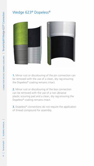
6
RUN
NIN
G M
AN
UA
LTe
naris
Hyd
rilC
oN
NeC
TIo
N S
peC
IfIC
RU
NN
ING
GU
IdeL
INeS
Tena
risH
ydril
Wed
ge 6
23® C
onne
ctio
n Wedge 623® Dopeless®
1. Minor rust or discolouring of the pin connection can be removed with the use of a clean, dry rag ensuring the Dopeless® coating remains intact.
2. Minor rust or discolouring of the box connection can be removed with the use of a non abrasive plastic scouring pad and a clean, dry rag ensuring the Dopeless® coating remains intact.
3. Dopeless® connections do not require the application of thread compound for assembly.

7
RUN
NIN
G M
AN
UA
LTe
naris
Hyd
ril
IDM
Cod
e G
DL0
0376
/3 /
Mar
ch 2
018
Co
NN
eCTI
oN
Spe
CIf
IC R
UN
NIN
G G
UID
eLIN
eS
Te
naris
Hyd
ril W
edge
623
® C
onne
ctio
nThread Compound ApplicationWedge 623® Dopeless®
If for whatever reason dope has to be applied to Wedge 623® Dopeless® connections, whether both pin and box are Dopeless® or when mixing a doped connection with a Dopeless® one apply thread compound as indicated below.
non dopeleSS® pin into dopeleSS® Box
.Apply a thin coating of thread compound on all pin threads, seals and pin nose.
.Ensure the area of the pin end from the last thread to the external seal area is completely and evenly covered with thread compound.
.Apply a thin coat of thread compound to box internal and external seal area.
dopeleSS® pin into Standard Box
.Apply a very thin coating of thread compound on all pin threads only.
.Do not dope pin seals or box connection.
dopeleSS® pin into dopeleSS® Box
.Apply a very thin layer of thread compound on all pin threads only.
.Do not dope pin seals or box connection.
NonDopeless® Box
Dopeless®
Box
Dope Threads and Sealsof Pin on Carbon.
Dope threads and Sealsof Pin and Box on Chrome.
Dope Pin Threads & Seals. Dope Box Seals.
NON DOPELESS® PIN
Dope Pin Threads Only
Dope PinThreads Only
DOPELESS® PIN

8
RUN
NIN
G M
AN
UA
LTe
naris
Hyd
rilC
oN
NeC
TIo
N S
peC
IfIC
RU
NN
ING
GU
IdeL
INeS
Tena
risH
ydril
Wed
ge 6
23® C
onne
ctio
n Thread Lock Application Non Dopeless® Connections
1. Ideally when running a Dopeless® string the connections to be thread locked should be non Dopeless® with the connections cleaned of thread compound and completely dried, then thread lock and dope applied as below:
Connections must be clean and dry when applying thread lock.
2. Thread lock should be applied to the threads furthest from the pin nose, approximately 50% of the threads should have thread lock applied.
3. Running compound should then be applied to the threads at the back of the box connection and internal seal.
4. Thread compound should also be applied to the pin external seal and area from last thread.

9
RUN
NIN
G M
AN
UA
LTe
naris
Hyd
ril
IDM
Cod
e G
DL0
0376
/3 /
Mar
ch 2
018
Co
NN
eCTI
oN
Spe
CIf
IC R
UN
NIN
G G
UID
eLIN
eS
Te
naris
Hyd
ril W
edge
623
® C
onne
ctio
nWedge 623® Dopeless® Thread Lock
1. When thread locking Dopeless® connections remove the Dopeless® coating from the threads on the pin connection where the thread lock is to be applied prior to the application of thread lock.
2. Leave the Dopeless® coating on the pin seals and threads where no thread lock is to be applied.
3. Dopeless® boxes should be washed with hot water then dried prior to thread locking.
4. Thread lock should be applied to the threads furthest from the pin nose, approximately 50% of the threads should have thread lock applied as per diagram on page 8.
5. Do not apply thread lock to seal areas.
6. The application of thread compound is not required.
Torque Application
1. Set tong dump valve at optimum torque then test on pipe body.
2. If dope is to be applied to Dopeless®, ‘double bump’ the first connection make up:
.Apply Dopeless® torques as per appropriate data sheet.
.Once optimum torque has been attained relax the tong and re-apply optimum torque.
.If movement over ½” is witnessed re-apply optimum torque +20%.

10
RUN
NIN
G M
AN
UA
LTe
naris
Hyd
rilC
oN
NeC
TIo
N S
peC
IfIC
RU
NN
ING
GU
IdeL
INeS
Tena
risH
ydril
Wed
ge 6
23® C
onne
ctio
n .Repeat process, checking to ensure no other factors are absorbing the applied torque.
.Often the issue is caused by excessive application of thread compound.
.Continue making up further joints applying higher torque if required.
.For connections ≥ 10 ¾” double bump every make up when dope is applied.
.Refer to the TenarisHydril Running Manual torque application section.
3. Do not apply the thread compound manufacturers friction correction factor.
4. Do not apply thread lock manufacturers friction factor, apply optimum torque + 20% then double bump the connection.
5. Computer make up equipment is not mandatory for Wedge 623® connections in carbon steel however it is recommended.
6. Computer make up equipment is highly recommended for Wedge 623® connections in chrome material.
7. Graph analysis for Wedge 623® is similar to that of Wedge 625® and Wedge Series 500™, refer to the TenarisHydril Running Manual make up acceptance section for further explanation.

11
RUN
NIN
G M
AN
UA
LTe
naris
Hyd
ril
IDM
Cod
e G
DL0
0376
/3 /
Mar
ch 2
018
Co
NN
eCTI
oN
Spe
CIf
IC R
UN
NIN
G G
UID
eLIN
eS
Te
naris
Hyd
ril W
edge
623
® C
onne
ctio
n8. If computer equipment is used to monitor connection make up, the graph profile should be similar to the ones below:
TOR
QU
E
0
0
20
40
60
80
100
120
2 4 6 8 10
TURNS
OPT 77,000 ft.lbs
MAX. 112,000 ft.lbs
MIN. 64,000 ft.lbs
TOR
QU
E
0.00 0.50
-1
1.00 2.50 3.00 3.50 4.00
TURNS
20
40
60
80
100
120
OPT 77,000 ft.lbs
MIN. 64,000 ft.lbs
9. Wedge 623® connection has limited same size /weight interchange capability, if mixing weight / grade ensure compatibility of design and apply the higher torque values of the two connections.
10. Wedge 623® is not compatible with Wedge 523®.

12
RUN
NIN
G M
AN
UA
LTe
naris
Hyd
rilC
oN
NeC
TIo
N S
peC
IfIC
RU
NN
ING
GU
IdeL
INeS
Tena
risH
ydril
Wed
ge 6
23® C
onne
ctio
n Running 1. The use of a stabbing guide is strongly recommended.
2. The use of slip type elevators are recommended.
3. The use of a safety clamp is strongly recommended when running Wedge 623® connections.
4. The use of a weight compensator is strongly recommended for chrome, large OD and heavy weight pipe.
5. Prior to stabbing ensure the rubber anti corrosion protection rings have been removed with the protectors and are not on the connection.
6. To avoid cross threading stab pipe in a smooth controlled fashion ensuring the pipe is vertical when doing so, continue to support and stabilise the pipe throughout the stabbing and make up operation.
7. For chrome material pipe spin in by hand with the use of a strap wrench.
8. Upon commencement of initial rotation use low RPM (5 RPM or below) in order to ensure the pipe has not cross threaded during stabbing. If cross threading is evident, immediately reverse rotate the pipe slowly.
9. Apply power tong at low RPM (do not exceed 5 RPM) for final make up.
10. Do not exceed 15 RPM during spin in.
11. Ensure back up tong is located below the box expanded area to prevent distortion of the connection.
12. Upon attainment of optimum torque there should be a slight gap between the box face and the start of the machined run out area.

13
RUN
NIN
G M
AN
UA
LTe
naris
Hyd
ril
IDM
Cod
e G
DL0
0376
/3 /
Mar
ch 2
018
Co
NN
eCTI
oN
Spe
CIf
IC R
UN
NIN
G G
UID
eLIN
eS
Te
naris
Hyd
ril W
edge
623
® C
onne
ctio
nPulling
1. Automatic stabbing system or stabber is highly recommended to maintain the pipe in a vertical position.
2. The use of a stabbing guide is recommended to assist in centralising the pin to prevent hang up.
3. Apply the back up tong jaw well below the expanded area of the box.
4. Apply power tong in low RPM (3-5 RPM) to break out the connection, ensuring the pipe is stabilized during the break out process.
5. Once the connection is broken release back up jaws and spin out below 15 RPM.
6. For Chrome material pipe, once the connection is broken spin out by hand with the use of a strap wrench.
7. It is recommended the stabbing guide is used when lifting the pin from the box to prevent hang up of the threads.
8. Visual inspection is recommended to classify the thread condition. Any rejected connections should be clearly marked and segregated for further investigation.
9. Apply clean, dry thread protectors.
10. Ensure clean, dry, Dopeless® protectors with seal rings correctly in place are installed.
11. For long term storage of Dopeless® connections, refurbishment by qualified personnel is recommended.

14
RUN
NIN
G M
AN
UA
LTe
naris
Hyd
rilC
oN
NeC
TIo
N S
peC
IfIC
RU
NN
ING
GU
IdeL
INeS
Tena
risH
ydril
Wed
ge 6
23® C
onne
ctio
n

1
RUN
NIN
G M
AN
UA
LTe
naris
Hyd
rilC
oN
NeC
TIo
N S
peC
IfIC
RU
NN
ING
GU
IdeL
INeS
Tena
risH
ydril
SLX
® C
onne
ctio
n
IdM
Cod
e G
dL2
3369
/1 /
Mar
ch 2
018
TenarisHydrilSLX® Connection
Scope
These guidelines apply specifically to the use of TenarisHydril SLX® connections. This document should be used in conjunction with the TenarisHydril Running Manual, which is the main document applicable to the running of all TenarisHydril premium connections.
References
.TenarisHydril Running Manual..Premium Connection Approved Thread Compounds TSH-MD-00.0002..Recommended guidelines for the field inspection of TenarisHydril connections, FSOG 13-005..SLX® Handling Plugs TN 9705.
Equipment, Material & Documents
1. Verify the appropriate thread compound is available.
2. Refer to document TSH-MD-00.0002 for a list of compounds approved by Tenaris.
3. Latest version of the specific Product Data Sheet can be obtained from Tenaris web site. In case this is unavailable, request the data sheet from the local Technical Sales representative or [email protected].

2
RUN
NIN
G M
AN
UA
LTe
naris
Hyd
rilC
oN
NeC
TIo
N S
peC
IfIC
RU
NN
ING
GU
IdeL
INeS
Tena
risH
ydril
SLX
® C
onne
ctio
n Pre-Running
1. Never move or handle pipe without the correct thread protectors securely in place.
2. Ensure connections are cleaned and free of all debris and / or contaminants, cleaning methods employed should conform to the recommendations contained within the TenarisHydril Running Manual.
3. Visually inspect threads and seal areas prior to running, ensuring no damage is evident.
4. Verify the connections to be assembled are genuine TenarisHydril manufactured connections.
5. Verify compatibility of the SLX® connection with any accessories such as pup joints, cross overs, cement heads, etc.
6. Verify material grade of all accessories ensuring compatibility with main string.
7. Check availability of handling plugs, minimum of 3 to ensure efficiency of running process.
8. Check the handling plugs are in good condition and fit correctly onto pipe.
9. Check single joint elevators have sufficient clearance to slide over box expanded area and seat against the handling plug.
10. Check the handling plugs are genuine TenarisHydril threads.
11. Verify handling plug number and maximum lift capacity.
12. Never exceed the maximum lift capacity.

3
RUN
NIN
G M
AN
UA
LTe
naris
Hyd
ril
IDM
Cod
e G
DL2
3369
/1 /
Mar
ch 2
018
Co
NN
eCTI
oN
Spe
CIf
IC R
UN
NIN
G G
UID
eLIN
eS
Te
naris
Hyd
ril S
LX® C
onne
ctio
n 13. Ensure handling plug OD / weight is compatible with pipe connections. SLX® has limited same OD / weight interchange capability.
14. Refer to the TenarisHydril running manual for the care and use of handling / lift plugs.
Inspection
1. Inspection criteria for all TenarisHydril connections is as outlined in the Field Service Operative Guideline FSOG 13-005.
2. Pay particular attention to seal areas.
3. Ensure the area from pin nose to seal has no tears, gouges or raised metal.
4. Ensure the pin and box torque shoulders have no dents, tears or raised material which would interfere with correct assembly.
5. Check box connections for mashes or ovality caused by transportation, handling or storage.

4
RUN
NIN
G M
AN
UA
LTe
naris
Hyd
rilC
oN
NeC
TIo
N S
peC
IfIC
RU
NN
ING
GU
IdeL
INeS
Tena
risH
ydril
SLX
® C
onne
ctio
n SLX® Configuration
ExtErnal SEal
IntErnal SEal

5
RUN
NIN
G M
AN
UA
LTe
naris
Hyd
ril
IDM
Cod
e G
DL2
3369
/1 /
Mar
ch 2
018
Co
NN
eCTI
oN
Spe
CIf
IC R
UN
NIN
G G
UID
eLIN
eS
Te
naris
Hyd
ril S
LX® C
onne
ctio
n
torquE ShouldEr
hookEd thrEad
ExtErnal SEal
IntErnal SEal
SEal SavEr

6
RUN
NIN
G M
AN
UA
LTe
naris
Hyd
rilC
oN
NeC
TIo
N S
peC
IfIC
RU
NN
ING
GU
IdeL
INeS
Tena
risH
ydril
SLX
® C
onne
ctio
n Thread Compound Application
For Carbon StEEl pIpE
1. Apply a thin coating of thread compound on the full pin end only, threads, seals and pin nose, the thread form should be clearly visible.
2. Do not apply running compound to the box end.
3. Thread compound should be cleaned from the box of carbon steel if received 'rig ready'.
For ChromE matErIal pIpE
1. Apply a thin coating of thread compound on both pin and box ensuring all threads, seals and pin nose are completely covered.
2. Do not over dope the connections, a thin even layer covering all surfaces is adequate. The thread form should be clearly visible.
3. Use approximately 50% of the quantity applied to the pin when doping the box.
4. Do not apply the thread compound manufacturers friction factor.
Carbon StEEl
ChromE matErIal

7
RUN
NIN
G M
AN
UA
LTe
naris
Hyd
ril
IDM
Cod
e G
DL2
3369
/1 /
Mar
ch 2
018
Co
NN
eCTI
oN
Spe
CIf
IC R
UN
NIN
G G
UID
eLIN
eS
Te
naris
Hyd
ril S
LX® C
onne
ctio
n Thread Lock Application
Connections must be clean and dry when applying thread lock.
1. Apply a thin coating of thread lock on the threads of the large step of the pin connection.
2. Do not apply thread lock on the seals or torque shoulder.
3. Apply thread compound to the box seals, torque shoulder and the threads of the small step of the connection.
4. Do not apply the thread lock manufacturer’s friction factor.
5. If the thread lock has a friction factor greater than 1, use maximum make up torque value indicated on the data sheet.

8
RUN
NIN
G M
AN
UA
LTe
naris
Hyd
rilC
oN
NeC
TIo
N S
peC
IfIC
RU
NN
ING
GU
IdeL
INeS
Tena
risH
ydril
SLX
® C
onne
ctio
n Torque Application
1. The use of computer make up analysis equipment is strongly recommended when assembling SLX® connections.
2. There are no defined shoulder points for SLX® connections, however a shoulder point must be in evidence.
3. Shoulder point must be lower than minimum make up torque and higher than reference torque.
4. Reference torque should initially be set at 5% of optimum torque.
5. The dump valve should be set at optimum torque, verify correct operation on the pipe body prior to first make up.
6. Set the computer turns to 1 initially then adjust as necessary to attain good graph depiction.
7. Refer to the TenarisHydril running manual make up acceptance section for further explanation.
8. The computer make up profile for SLX® connections should be similar to the ones below.

9
RUN
NIN
G M
AN
UA
LTe
naris
Hyd
ril
IDM
Cod
e G
DL2
3369
/1 /
Mar
ch 2
018
Co
NN
eCTI
oN
Spe
CIf
IC R
UN
NIN
G G
UID
eLIN
eS
Te
naris
Hyd
ril S
LX® C
onne
ctio
n
9. SLX® connections have limited same size different weight interchange capability, refer to TenarisHydril premium connections catalogue for interchange capability.
10. If different weight or grade of connections are to be mixed apply the lower of the indicated make up torques.
TOP SHD
TOR
QU
E
6.60 7.00
0
5000
10000
15000
20000
25000
27995
7.40 7.80 8.20 8.60 9.00 9.40 9.80
TURNS
MAX.
OPT.
TOP SHD
TOR
QU
E
3.40 3.80
0
5000
10000
15000
20000
25000
30000
3500032890
4.20 4.60 5.00 5.40 5.80 6.20 6.60
TURNS
MAX.
OPT.
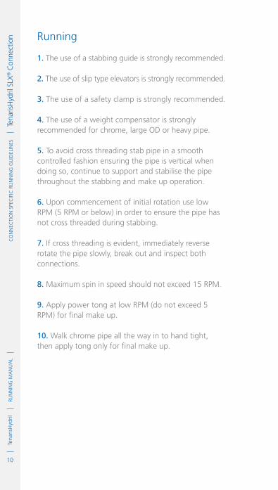
10
RUN
NIN
G M
AN
UA
LTe
naris
Hyd
rilC
oN
NeC
TIo
N S
peC
IfIC
RU
NN
ING
GU
IdeL
INeS
Tena
risH
ydril
SLX
® C
onne
ctio
n Running 1. The use of a stabbing guide is strongly recommended.
2. The use of slip type elevators is strongly recommended.
3. The use of a safety clamp is strongly recommended.
4. The use of a weight compensator is strongly recommended for chrome, large OD or heavy pipe.
5. To avoid cross threading stab pipe in a smooth controlled fashion ensuring the pipe is vertical when doing so, continue to support and stabilise the pipe throughout the stabbing and make up operation.
6. Upon commencement of initial rotation use low RPM (5 RPM or below) in order to ensure the pipe has not cross threaded during stabbing.
7. If cross threading is evident, immediately reverse rotate the pipe slowly, break out and inspect both connections.
8. Maximum spin in speed should not exceed 15 RPM.
9. Apply power tong at low RPM (do not exceed 5 RPM) for final make up.
10. Walk chrome pipe all the way in to hand tight, then apply tong only for final make up.

11
RUN
NIN
G M
AN
UA
LTe
naris
Hyd
ril
IDM
Cod
e G
DL2
3369
/1 /
Mar
ch 2
018
Co
NN
eCTI
oN
Spe
CIf
IC R
UN
NIN
G G
UID
eLIN
eS
Te
naris
Hyd
ril S
LX® C
onne
ctio
n Pulling
1. Automatic stabbing system or stabber is highly recommended to maintain the pipe in a vertical position.
2. The use of a stabbing guide is recommended to assist in centralizing the pin to prevent hang up.
3. The use of slip type elevators is strongly recommended.
4. The use of a safety clamp is strongly recommended.
5. A weight compensator is strongly recommended for chrome, large OD and heavy pipe.
6. Apply the back up tong jaw on the pipe body, never grip the box connection.
7. Apply power tong in low RPM (3-5 RPM) to break out the connection, ensuring the pipe is stabilised during the break and spin out process.
8. Walk chrome pipe all the way out after initial break out.
9. Visual inspection is recommended to classify the thread condition. Any rejected connections should be clearly marked and segregated for further investigation.
10. Apply clean, dry thread protectors after applying storage compound on clean, dry connections.
11. Storage / thread compound should always be applied to connections post job, even rejects.

12
RUN
NIN
G M
AN
UA
LTe
naris
Hyd
rilC
oN
NeC
TIo
N S
peC
IfIC
RU
NN
ING
GU
IdeL
INeS
Tena
risH
ydril
SLX
® C
onne
ctio
n

1
RUN
NIN
G M
AN
UA
LTe
naris
Hyd
rilC
oN
NeC
TIo
N S
peC
IfIC
RU
NN
ING
GU
IdeL
INeS
Tena
risH
ydril
MA
CII™
Con
nect
ion
IdM
Cod
e G
dL2
3370
/1 /
Mar
ch 2
018
TenarisHydrilMACII™ ConnectionScope
These guidelines apply specifically to the use of TenarisHydril MACII™ connections. This document should be used in conjunction with the TenarisHydril Running Manual, which is the main document applicable to the running of all TenarisHydril Premium Connections.
References
.TenarisHydril Running Manual..Premium Connection Approved Thread Compounds TSH-MD-00.0002..Recommended guidelines for the field inspection of TenarisHydril connections, FSOG 13-005..MACII™ Handling Plugs TN 9804.
Equipment, Material & Documents
1. Verify the appropriate thread compound is available.
2. Refer to document TSH-MD-00.0002 for a list of compounds approved by Tenaris.
3. Latest version of the specific Product Data Sheet can be obtained from Tenaris website. In case this is unavailable, request the data sheet from the local Technical Sales representative or [email protected].

2
RUN
NIN
G M
AN
UA
LTe
naris
Hyd
rilC
oN
NeC
TIo
N S
peC
IfIC
RU
NN
ING
GU
IdeL
INeS
Tena
risH
ydril
MA
CII™
Con
nect
ion Pre-Running
1. Never move or handle pipe without the correct thread protectors securely in place.
2. Ensure connections are cleaned and free of all debris and / or contaminants, cleaning methods employed should conform to the recommendations contained within the TenarisHydril Running Manual.
3. Visually inspect threads and seal areas prior to running, ensuring no damage is evident.
4. Verify the connections to be assembled are genuine TenarisHydril manufactured connections.
5. Verify compatibility of the MACII™ connection with any accessories such as pup joints, cross overs, cement heads, etc.
6. Verify material grade of all accessories ensuring compatibility with main string.
7. On Dopeless® connections check condition of pin and box coating ensuring no peel off or degradation has occurred.
8. Check availability of handling plugs, minimum of 3 to ensure efficiency of running process.
9. Check the handling plugs are in good condition and fit correctly onto pipe.
10. Check single joint elevators have sufficient clearance to slide over box expanded area and seat against the handling plug.

3
RUN
NIN
G M
AN
UA
LTe
naris
Hyd
ril
IDM
Cod
e G
DL2
3370
/1 /
Mar
ch 2
018
Co
NN
eCTI
oN
Spe
CIf
IC R
UN
NIN
G G
UID
eLIN
eS
Te
naris
Hyd
ril M
AC
II™ C
onne
ctio
n 11. Check the handling plugs are genuine TenarisHydril threads.
12. Verify handling plug number and maximum lift capacity.
13. Never exceed the maximum lift capacity.
14. Ensure handling plug OD / weight is compatible with pipe connections, MACII™ has limited same OD / weight interchange capability.
15. Refer to the TenarisHydril running manual for the care and use of handling / lift plugs.
Inspection
1. Inspection criteria for all TenarisHydril connections is as outlined in the Field Service Operative Guideline FSOG 13-005.
2. Pay particular attention to seal areas.
3. Ensure the area from pin nose to seal has no tears, gouges or raised metal.
4. Ensure the pin and box torque shoulders have no dents, tears or raised material which could interfere with correct assembly.
5. Check box connections for mashes or ovality caused by transportation, handling or storage.

4
RUN
NIN
G M
AN
UA
LTe
naris
Hyd
rilC
oN
NeC
TIo
N S
peC
IfIC
RU
NN
ING
GU
IdeL
INeS
Tena
risH
ydril
MA
CII™
Con
nect
ion MAC II™ Configuration
Hooked Thread

5
RUN
NIN
G M
AN
UA
LTe
naris
Hyd
ril
IDM
Cod
e G
DL2
3370
/1 /
Mar
ch 2
018
Co
NN
eCTI
oN
Spe
CIf
IC R
UN
NIN
G G
UID
eLIN
eS
Te
naris
Hyd
ril M
AC
II™ C
onne
ctio
n
ExtErnal SEal
torquE ShouldEr
IntErnal SEal

6
RUN
NIN
G M
AN
UA
LTe
naris
Hyd
rilC
oN
NeC
TIo
N S
peC
IfIC
RU
NN
ING
GU
IdeL
INeS
Tena
risH
ydril
MA
CII™
Con
nect
ion Thread Compound Application
For Carbon StEEl pIpE
1. Apply a thin coating of thread compound on the full pin end only, threads, seals and pin nose, the thread form should be clearly visible.
2. Do not apply running compound to the box end.
3. Thread compound should be cleaned from the box of carbon steel if received 'rig ready'.
For ChromE matErIal pIpE
1. Apply a thin coating of thread compound on both pin and box ensuring all threads, seals and pin nose are completely covered.
2. Do not over dope the connections, a thin even layer covering all surfaces is adequate. The thread form should be clearly visible.
3. Use approximately 50% of the quantity applied to the pin when doping the box.
4. Do not apply the thread compound manufacturer’s friction factor.
Carbon StEEl
ChromE matErIal

7
RUN
NIN
G M
AN
UA
LTe
naris
Hyd
ril
IDM
Cod
e G
DL2
3370
/1 /
Mar
ch 2
018
Co
NN
eCTI
oN
Spe
CIf
IC R
UN
NIN
G G
UID
eLIN
eS
Te
naris
Hyd
ril M
AC
II™ C
onne
ctio
n Thread Lock Application
Connections must be clean and dry when applying thread lock.
1. Apply a thin coating of thread lock on the threads of the large step of the pin connection.
2. Do not apply thread lock on the seals or torque shoulder.
3. Apply thread compound to the box internal seal, torque shoulder and the threads of the small step of the connection.
4. Apply thread compound to the pin external seal.
5. Do not apply the thread lock manufacturer’s friction factor.
6. If the thread lock has a friction factor greater than 1, use maximum make up torque value indicated on the data sheet.

8
RUN
NIN
G M
AN
UA
LTe
naris
Hyd
rilC
oN
NeC
TIo
N S
peC
IfIC
RU
NN
ING
GU
IdeL
INeS
Tena
risH
ydril
MA
CII™
Con
nect
ion MAC II™ Dopeless®
1. Minor rust or discolouring of the pin connection can be removed with the use of a clean, dry rag ensuring the Dopeless® coating remains intact.
2. Minor rust or discolouring of the box connection can be removed with the use of a non abrasive plastic scouring pad and a clean dry rag ensuring the Dopeless® coating remains intact.
3. Dopeless connections do not require the application of thread compound for make up.
4. If for whatever reason thread compound has to be applied to MACII™ Dopeless® connections, whether both pin and box are Dopeless® or when mixing a doped connection with Dopeless®, apply thread compound as indicated below.

9
RUN
NIN
G M
AN
UA
LTe
naris
Hyd
ril
IDM
Cod
e G
DL2
3370
/1 /
Mar
ch 2
018
Co
NN
eCTI
oN
Spe
CIf
IC R
UN
NIN
G G
UID
eLIN
eS
Te
naris
Hyd
ril M
AC
II™ C
onne
ctio
n non dopElESS® pIn Into dopElESS® box
.Apply a thin coating of thread compound on all pin threads, seals and pin nose.
.Apply a thin coat of thread compound to box internal seal and torque shoulder.
dopElESS® pIn Into Standard box
.Apply a very thin coating of thread compound on all pin threads only.
.Do not dope pin seals or box connection. dopElESS® pIn Into dopElESS® box
.Apply a very thin layer of thread compound on all pin threads only.
.Do not dope pin seal or box connection.
StandardBox
Dopeless®
Box
See page 6
Dope Pin Threads, Seals& Shoulder. Dope Box Seals.
STANDARD PIN
Dope Pin Threads Only
Dope PinThreads Only
DOPELESS® PIN
If applying thread compound to Dopeless® connections use the doped variant torque values.

10
RUN
NIN
G M
AN
UA
LTe
naris
Hyd
rilC
oN
NeC
TIo
N S
peC
IfIC
RU
NN
ING
GU
IdeL
INeS
Tena
risH
ydril
MA
CII™
Con
nect
ion MAC II™ Dopeless® Thread Lock
1. Ideally when running a Dopeless® string the connections to be thread locked should be the non Dopeless® variant with the connections cleaned of thread compound and completely dried, then thread lock and dope applied as per the diagram on page 7.
2. When thread locking Dopeless® connections remove the Dopeless® coating from the threads on the pin connection where the thread lock is to be applied prior to the application of thread lock.
3. Leave the Dopeless® coating on the pin seals, torque shoulder and threads where no thread lock is to be applied.
4. Dopeless® boxes should be washed with hot water then dried prior to thread locking.
5. Thread lock should be applied to the threads of the large step on the pin, as per the diagram on page 7.
6. The application of thread dope is not required.
7. When assembling Dopeless® connections with thread lock, apply the non Dopeless® torque values taken from the standard product data sheet.
8. Do not apply the thread lock manufacturers friction factor.
9. If the thread lock has a friction factor greater than 1 use maximum make up torque value indicated on the data sheet.

11
RUN
NIN
G M
AN
UA
LTe
naris
Hyd
ril
IDM
Cod
e G
DL2
3370
/1 /
Mar
ch 2
018
Co
NN
eCTI
oN
Spe
CIf
IC R
UN
NIN
G G
UID
eLIN
eS
Te
naris
Hyd
ril M
AC
II™ C
onne
ctio
n Torque Application
1. The use of computer make up analysis equipment is strongly recommended when assembling MACII™ connections.
2. There are no defined shoulder points for MACII™ connections, however a shoulder point must be in evidence.
3. Shoulder point must be lower than minimum make up torque and higher than reference torque.
4. Reference torque should initially be set at 5% of optimum torque.
5. The dump valve should be set at optimum torque, verify correct operation on the pipe body prior to first make up.
6. Set the computer turns to 1 initially then adjust as necessary to attain good graph depiction.
7. Refer to the TenarisHydril running manual make up acceptance section for further explanation.
8. The computer make up profile for MACII™ connections should be similar to the ones below.
TOR
QU
E *
1000
ft-
lbs
MAX. 46000
0
0
1.1
2.2
3.3
4.4
0.40 0.80 1.20 1.60
TURNS
MIN. 38000
OPT 42000

12
RUN
NIN
G M
AN
UA
LTe
naris
Hyd
rilC
oN
NeC
TIo
N S
peC
IfIC
RU
NN
ING
GU
IdeL
INeS
Tena
risH
ydril
MA
CII™
Con
nect
ion
9. MACII™ connections have limited same size different weight interchangeability, refer to TenarisHydril premium connections catalogue for interchange capability.
10. If different weight or grade of connections are to be mixed apply the lower of the indicated make up torques.
11. When assembling Dopeless® connections the torques applied must be taken from the Dopeless® variant product data sheet.
12. When mixing standard doped and Dopeless® connections apply doped variant torque values.
TOR
QU
E *
1000
ft-
lbs
MAX. 46000
0
0
1.1
2.2
3.3
4.4
0.40 0.80 1.20 1.60
TURNS
MIN. 38000
OPT 42000

13
RUN
NIN
G M
AN
UA
LTe
naris
Hyd
ril
IDM
Cod
e G
DL2
3370
/1 /
Mar
ch 2
018
Co
NN
eCTI
oN
Spe
CIf
IC R
UN
NIN
G G
UID
eLIN
eS
Te
naris
Hyd
ril M
AC
II™ C
onne
ctio
n Running 1. The use of a stabbing guide is strongly recommended.
2. The use of slip type elevators are recommended.
3. The use of a safety clamp is strongly recommended when running MACII™ connections.
4. The use of a weight compensator is strongly recommended for chrome, large OD or heavy pipe.
5. To avoid cross threading stab pipe in a smooth controlled fashion ensuring the pipe is vertical when doing so, continue to support and stabilise the pipe throughout the stabbing and make up operation.
6. Upon commencement of initial rotation use low RPM (5 RPM or below) in order to ensure the pipe has not cross threaded during stabbing.
7. If cross threading is evident, immediately reverse rotate the pipe, completely disassemble, clean and inspect both connections.
8. Maximum spin in speed should not exceed 15 RPM.
9. Apply power tong at low RPM (do not exceed 5 RPM) for final make up.
10. Walk chrome pipe all the way in to hand tight then apply tong only for final make up.

14
RUN
NIN
G M
AN
UA
LTe
naris
Hyd
rilC
oN
NeC
TIo
N S
peC
IfIC
RU
NN
ING
GU
IdeL
INeS
Tena
risH
ydril
MA
CII™
Con
nect
ion Pulling
1. Automatic stabbing system or stabber is strongly recommended to stabilise the pipe vertically.
2. The use of a stabbing guide is recommended to prevent hang up.
3. The use of a safety clamp is strongly recommended.
4. The use of a weight compensator is strongly recommended for chrome, large OD and heavy pipe.
5. Apply the back up tong jaw on the pipe body, never grip the box connection.
6. Apply power tong in low RPM (3-5 RPM) to break the connection, ensuring the pipe is stabilised during the break and spin out process.
7. Walk chrome pipe all the way out after initial break out.
8. Visual inspection is recommended to classify the thread condition. Any rejected connections should be clearly marked and segregated for further investigation.
9. Apply clean, dry thread protectors after applying storage compound on clean, dry connections.
10. Storage / thread compound should always be applied to connections post job, even rejects.
11. Do not apply storage compound to Dopeless® connections.
12. For long term storage of Dopeless® connections, refurbishment by qualified personnel prior to applying Dopeless® specific protectors is recommended.
13. Ensure clean, dry, Dopeless® protectors with seal rings correctly in place are installed.

1
RUN
NIN
G M
AN
UA
LTe
naris
Hyd
rilC
oN
NeC
TIo
N S
peC
IfIC
RU
NN
ING
GU
IdeL
INeS
Tena
risH
ydril
eR™
Con
nect
ionTenarisHydril
ER™ Connection
Scope
These guidelines apply specifically to the use of TenarisHydril ER™ (Easy Running) connections. This document should be used in conjunction with the TenarisHydril Running Manual, which is the main document applicable to the running of all TenarisHydril premium connections.
References
.TenarisHydril Running Manual..Premium Connection Approved Thread Compounds TSH-MD-00.0002..Recommended guidelines for the field inspection of TenarisHydril connections, FSOG 13-005.
Equipment, Material & Documents
1. Verify the appropriate thread compound is available.
2. Refer to document TSH-MD-00.0002 for a list of compounds approved by Tenaris.
3. Latest version of the specific Product Data Sheet can be obtained from the Tenaris web site. In case this is unavailable, request the data sheet from the local Technical Sales representative or [email protected].
IDM
Cod
e G
DL2
3469
/1 /
Mar
ch 2
018

2
RUN
NIN
G M
AN
UA
LTe
naris
Hyd
rilC
oN
NeC
TIo
N S
peC
IfIC
RU
NN
ING
GU
IdeL
INeS
Tena
risH
ydril
eR™
Con
nect
ion Pre-Running
1. Never move or handle pipe without the correct thread protectors securely in place
2. Ensure connections are cleaned and free of all debris and / or contaminants, cleaning methods employed should conform to the recommendations contained within the TenarisHydril Running Manual.
3. Verify all pipe and accessories have genuine TenarisHydril manufactured connections.
4. Visually inspect threads and torque shoulder prior to running, ensuring no damage is evident.
5. On Dopeless® connections, check condition of both pin and box coating ensuring no peel off or degradation has occurred.
6. Verify the compatibility of the ER™ connection with any accessories such as, cement heads, safety valves, cross overs, etc.
7. Verify material grade of all accessories ensuring compatibility with main string.
Inspection
1. Inspection criteria for all TenarisHydril connections is as outlined in the Field Service Operative Guideline FSOG 13-005.
2. Ensure the pin and box torque shoulders have no dents, tears or raised material which could interfere with correct assembly.

3
RUN
NIN
G M
AN
UA
LTe
naris
Hyd
rilC
oN
NeC
TIo
N S
peC
IfIC
RU
NN
ING
GU
IdeL
INeS
Tena
risH
ydril
eR™
Con
nect
ion
IdM
Cod
e G
dL2
3469
/1 /
Mar
ch 2
018
ER™ Configuration
7" > 13 5/8" = 4 TPI 14" > 24 1/2" = 3 TPINo Metal to Metal seal
torqueshoulder

4
RUN
NIN
G M
AN
UA
LTe
naris
Hyd
rilC
oN
NeC
TIo
N S
peC
IfIC
RU
NN
ING
GU
IdeL
INeS
Tena
risH
ydril
eR™
Con
nect
ion Thread Compound Application
1. Apply a thin coating of thread compound on the pin and box connections, fully covering all threads, pin nose and box torque shoulder, the thread form should be fully visible.
2. Use approximately 50% of the quantity applied to the pin when doping the box.
3. For Tenaris approved thread compounds, apply the friction factor indicated in TSH-MD-00.0002. For thread compounds other than those listed, apply the thread compound manufacturers indicated friction factor.

5
RUN
NIN
G M
AN
UA
LTe
naris
Hyd
rilC
oN
NeC
TIo
N S
peC
IfIC
RU
NN
ING
GU
IdeL
INeS
Tena
risH
ydril
eR™
Con
nect
ion
IdM
Cod
e G
dL2
3469
/1 /
Mar
ch 2
018
Thread Lock Application
Connections must be clean and dry when applying thread lock.
1. Apply a thin coating of thread lock on 50% of the pin threads furthest from the pipe body.
2. Do not apply thread lock on the torque shoulder.
3. Apply thread compound to the box torque shoulder.
4. Apply the thread lock manufacturers indicated friction factor.

6
RUN
NIN
G M
AN
UA
LTe
naris
Hyd
rilC
oN
NeC
TIo
N S
peC
IfIC
RU
NN
ING
GU
IdeL
INeS
Tena
risH
ydril
eR™
Con
nect
ion ER™ Dopeless®
1. Minor rust or discolouring of the pin connection can be removed with the use of a clean, dry rag ensuring the Dopeless® coating remains intact.
2. Minor rust or discolouring of the box connection can be removed with the use of a non abrasive plastic scouring pad and a clean, dry rag ensuring the Dopeless® coating remains intact.
3. Dopeless® connections do not require the application of thread compound for make up.
4. If for whatever reason thread compound has to be applied to ER™ Dopeless® connections, whether both pin and box are Dopeless® or when mixing a doped connection with Dopeless®, apply thread compound as indicated below.

7
RUN
NIN
G M
AN
UA
LTe
naris
Hyd
rilC
oN
NeC
TIo
N S
peC
IfIC
RU
NN
ING
GU
IdeL
INeS
Tena
risH
ydril
eR™
Con
nect
ion
IdM
Cod
e G
dL2
3469
/1 /
Mar
ch 2
018
NoN dopeless® piN iNto dopeless® box
.Apply a thin coating of thread compound on all pin threads and pin nose.
.Apply a thin coat of thread compound to box torque shoulder. dopeless® piN iNto staNdard box
.Apply a very thin coating of thread compound on all pin threads only.
.Do not dope box connection. dopeless® piN iNto dopeless® box
.Apply a very thin layer of thread compound on all pin threads only.
.Do not dope box connection.
StandardBox
Dopeless®
Box
See page 4
Dope Pin Thread & Shoulder. Dope Box shoulder.
STANDARD PIN
Dope Pin Threads Only
Dope PinThreads Only
DOPELESS® PIN
If applying thread compound to Dopeless® connections use the doped variant torque values.
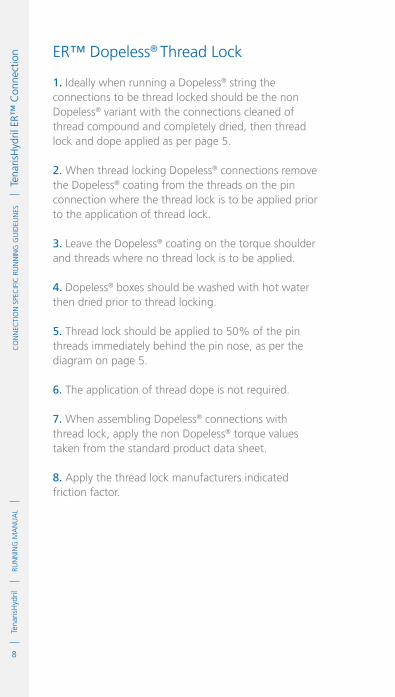
8
RUN
NIN
G M
AN
UA
LTe
naris
Hyd
rilC
oN
NeC
TIo
N S
peC
IfIC
RU
NN
ING
GU
IdeL
INeS
Tena
risH
ydril
eR™
Con
nect
ion ER™ Dopeless® Thread Lock
1. Ideally when running a Dopeless® string the connections to be thread locked should be the non Dopeless® variant with the connections cleaned of thread compound and completely dried, then thread lock and dope applied as per page 5.
2. When thread locking Dopeless® connections remove the Dopeless® coating from the threads on the pin connection where the thread lock is to be applied prior to the application of thread lock.
3. Leave the Dopeless® coating on the torque shoulder and threads where no thread lock is to be applied.
4. Dopeless® boxes should be washed with hot water then dried prior to thread locking.
5. Thread lock should be applied to 50% of the pin threads immediately behind the pin nose, as per the diagram on page 5.
6. The application of thread dope is not required.
7. When assembling Dopeless® connections with thread lock, apply the non Dopeless® torque values taken from the standard product data sheet.
8. Apply the thread lock manufacturers indicated friction factor.

9
RUN
NIN
G M
AN
UA
LTe
naris
Hyd
rilC
oN
NeC
TIo
N S
peC
IfIC
RU
NN
ING
GU
IdeL
INeS
Tena
risH
ydril
eR™
Con
nect
ion
IdM
Cod
e G
dL2
3469
/1 /
Mar
ch 2
018
Torque Application
1. The use of computer make up analysis equipment is strongly recommended when assembling ER™ connections.
2. Shoulder points for ER™ connections.
.Minimum 15% of optimum.
.Maximum 80% of optimum. 3. Reference torque should initially be set at 5% of optimum.
4. The dump valve should be set at optimum, verify correct operation on the pipe body prior to first make up.
5. Set the computer turns to 2 initially then adjust as necessary to attain good graph depiction.
6. Refer to the TenarisHydril running manual make up acceptance section for further explanation.
7. The computer make up profile for ER™ connections should be similar to the ones below.
TOR
QU
E *
1000
ft-
lbs
0
0
1.2
2.4
3.6
4.8
0.32 0.64 0.96 1.28
TURNS
OPT 48500
MAX. SHL 38800
MIN. 46015MAX. 49800
MIN. SHL 7275

10
RUN
NIN
G M
AN
UA
LTe
naris
Hyd
rilC
oN
NeC
TIo
N S
peC
IfIC
RU
NN
ING
GU
IdeL
INeS
Tena
risH
ydril
eR™
Con
nect
ion
8. If different weight or grade of connections are to be mixed apply the lower of the indicated make up torques.
9. When assembling ER™ Dopeless® connections the torques applied must be taken from the Dopeless® variant product data sheet.
10. When mixing standard doped and Dopeless® connections apply doped variant torque values.
11. ER™ pipe ≥ 13 3/8” should have a make up loss (MUL) indicator stamped around the circumference of the pin OD. This MUL indicator is to assist in the visual verification of correct assembly and eradicates the necessity of applying the MUL by hand, however this does not replace the requirement for a good make up graph as the primary acceptance / rejection criteria for connection assembly.
12. After make up the face of the coupling should finish at the lower edge of the make up band (edge closer to the pin nose).
TOR
QU
E *
1000
ft-
lbs
0
0
1.2
2.4
3.6
4.8
0.32 0.64 0.96 1.28
TURNS
OPT 48500
MAX. SHL 38800
MIN. 46015MAX. 49800
MIN. SHL 7275

11
RUN
NIN
G M
AN
UA
LTe
naris
Hyd
rilC
oN
NeC
TIo
N S
peC
IfIC
RU
NN
ING
GU
IdeL
INeS
Tena
risH
ydril
eR™
Con
nect
ion
IdM
Cod
e G
dL2
3469
/1 /
Mar
ch 2
018
13. The make up band may be located within the thread run out area and may be of a different configuration to the one indicated above. The distance from the pipe end to the make up band should always be checked in order to verify it corresponds to the MUL indicated on the latest product data sheet.
14. For ease of identification after make up it is recommended the make up band be highlighted with a paint stick or some other form of marker prior to connection assembly.
15. Older pipe may in some regions have a make up triangle (possibly three) hard stamped on the pin ends as a visual indicator of complete make up. When made up the coupling face should reach the base of this triangle. Best practice is to check randomly that the distance from the base of these triangles to the pin nose corresponds to the make up loss indicated on the product data sheet.
reF. 5/16"
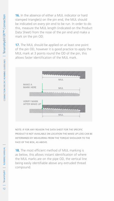
12
RUN
NIN
G M
AN
UA
LTe
naris
Hyd
rilC
oN
NeC
TIo
N S
peC
IfIC
RU
NN
ING
GU
IdeL
INeS
Tena
risH
ydril
eR™
Con
nect
ion 16. In the absence of either a MUL indicator or hard
stamped triangle(s) on the pin end, the MUL should be indicated on every pin end to be run. In order to do this, measure the MUL length (indicated on the Product Data Sheet) from the nose of the pin end and make a mark on the pin OD.
17. The MUL should be applied on at least one point of the pin OD, however it is good practice to apply the MUL mark at 3 points round the OD of the pin, this allows faster identification of the MUL mark.
Note: iF For aNy reasoN the data sheet For the speciFic
product is Not available oN locatioN the make up loss caN be
determiNed by measuriNg From the torque shoulder to the
Face oF the box, as above.
18. The most efficient method of MUL marking is as below, this allows instant identification of where the MUL marks are on the pipe OD, the vertical line being easily identifiable above any extruded thread compound.
MUL
MUL
MUL
MAKE AMARK HERE
VERIFY MARKAFTER MAKE-UP

13
RUN
NIN
G M
AN
UA
LTe
naris
Hyd
rilC
oN
NeC
TIo
N S
peC
IfIC
RU
NN
ING
GU
IdeL
INeS
Tena
risH
ydril
eR™
Con
nect
ion
IdM
Cod
e G
dL2
3469
/1 /
Mar
ch 2
018
Running 1. The use of a stabbing guide is strongly recommended.
2. The use of a weight compensator is strongly recommended for large OD and heavy weight pipe.
3. To avoid cross threading stab pipe in a smooth controlled fashion ensuring the pipe is vertical when doing so, continue to support and stabilise the pipe throughout the stabbing and make up operation.
4. Upon commencement of initial rotation use low RPM (5 RPM or below) in order to ensure the pipe has not cross threaded during stabbing.
5. If cross threading is evident, immediately reverse rotate the pipe, completely disassemble, clean and inspect both connections.
6. Maximum spin in speed should not exceed 15 RPM.
7. Apply power tong at low RPM (do not exceed 5 RPM), for final make up.
make up loss

14
RUN
NIN
G M
AN
UA
LTe
naris
Hyd
rilC
oN
NeC
TIo
N S
peC
IfIC
RU
NN
ING
GU
IdeL
INeS
Tena
risH
ydril
eR™
Con
nect
ion Pulling
1. Automatic stabbing system or stabber is highly recommended to maintain the pipe in a vertical position.
2. The use of a stabbing guide is recommended to assist in centralising the pin to prevent hang up.
3. A weight compensator is strongly recommended for large OD and heavy pipe.
4. Apply the back up tong jaw on the lower part, over the mill end of the coupling.
5. Apply power tong in low RPM (3-5 RPM) to break the connection, ensuring the pipe is stabilised during the break and spin out process.
6. Visual inspection is recommended to classify the thread condition. Any rejected connections should be clearly marked and segregated for further investigation.
7. Apply clean, dry thread protectors after applying storage compound on clean, dry connections.
8. Storage / thread compound should always be applied to connections post job, even rejects.
9. Do not apply storage compound to Dopeless® connections.
10. For long term storage of Dopeless® connections, refurbishment by qualified personnel prior to applying Dopeless® specific protectors is recommended.
11. Ensure clean, dry, Dopeless® protectors with seal rings correctly in place are installed.
1
RUN
NIN
G M
AN
UA
LTe
naris
Hyd
rilC
oN
NeC
TIo
N S
peC
IfIC
RU
NN
ING
GU
IdeL
INeS
Tena
risH
ydril
MS™
& M
S X
T/X
C™
Con
nect
ions
IdM
Cod
e G
dL2
3372
/1 /
Mar
ch 2
018
TenarisHydrilMS™ & MS XT/XC™ ConnectionsScope
These guidelines apply specifically to the use of TenarisHydril MS™ and MS XT/XC™ connections. This document should be used in conjunction with the TenarisHydril Running Manual, which is the main document applicable to the running of all TenarisHydril Premium Connections.
References
.TenarisHydril Running Manual..Premium Connection Approved Thread Compounds TSH-MD-00.0002..Recommended guidelines for the field inspection of TenarisHydril connections, FSOG 13-005.
Equipment, Material & Documents
1. Verify the appropriate thread compound is available.
2. Refer to document TSH-MD-00.0002 for a list of compounds approved by Tenaris.
3. Latest version of the specific Product Data Sheet can be obtained from Tenaris web site. In case this is unavailable, request the data sheet from the local Technical Sales representative or [email protected].

2
RUN
NIN
G M
AN
UA
LTe
naris
Hyd
rilC
oN
NeC
TIo
N S
peC
IfIC
RU
NN
ING
GU
IdeL
INeS
Tena
risH
ydril
MS™
& M
S X
T/X
C™
Con
nect
ions Pre-Running
1. Never move or handle pipe without the correct thread protectors securely in place.
2. Ensure connections are clean and free of all debris and / or contaminants, cleaning methods employed should conform to the recommendations contained within the TenarisHydril Running Manual.
3. Verify all pipe and accessories have genuine TenarisHydril manufactured connections.
4. Visually inspect thread and seal areas prior to running, ensuring no damage is evident.
5. Verify the compatibility of the MS™ or MS XT/XC™ connection with accessories such as cement heads, safety valves, cross overs, etc.
6. Verify material grade of all accessories ensuring compatibility with main string.
Inspection
1. Inspection criteria for all TenarisHydril connections is as outlined in the Field Service Operative Guideline FSOG 13-005.
2. Pay particular attention to seal areas.
3. Ensure the pin nose has no tears, gouges or raised metal.
4. Ensure the pin and box torque shoulders have no dents, tears or raised material which could interfere with correct assembly.

3
RUN
NIN
G M
AN
UA
LTe
naris
Hyd
ril
IDM
Cod
e G
DL2
3372
/1 /
Mar
ch 2
018
Co
NN
eCTI
oN
Spe
CIf
IC R
UN
NIN
G G
UID
eLIN
eS
Te
naris
Hyd
ril M
S™ &
MS
XT/
XC
™ C
onne
ctio
nsMS™ / MS XT/XC™ Configuration
8 TPI 2 3/8" > 2 7/8"6 TPI 3 1/2" > 4 1/2"5 TPI 5" > 5 1/2"4 TPI 6 5/8" > 13 3/8" 3 TPI 14"
SEAL
torquEShouLdEr

4
RUN
NIN
G M
AN
UA
LTe
naris
Hyd
rilC
oN
NeC
TIo
N S
peC
IfIC
RU
NN
ING
GU
IdeL
INeS
Tena
risH
ydril
MS™
& M
S X
T/X
C™
Con
nect
ions Thread Compound Application
1. Apply a thin coating of thread compound on the pin and box connections, fully covering all threads, seals, pin nose and box torque shoulder, the thread form should be fully visible.
2. Use approximately 50% of the quantity applied to the pin when doping the box.
3. For Tenaris approved thread compounds, apply the friction factor indicated in TSH-MD-00.0002. For thread compounds other than those listed, apply the thread compound manufacturers' indicated friction factor.

5
RUN
NIN
G M
AN
UA
LTe
naris
Hyd
ril
IDM
Cod
e G
DL2
3372
/1 /
Mar
ch 2
018
Co
NN
eCTI
oN
Spe
CIf
IC R
UN
NIN
G G
UID
eLIN
eS
Te
naris
Hyd
ril M
S™ &
MS
XT/
XC
™ C
onne
ctio
nsThread Lock Application
Connections must be clean and dry when applying thread lock.
1. Apply a thin coating of thread lock on 50% of the pin threads furthest from the pipe body.
2. Do not apply thread lock on the seal or torque shoulder.
3. Apply thread compound to the box seal and torque shoulder.
4. Apply the thread lock manufacturers indicated friction factor.

6
RUN
NIN
G M
AN
UA
LTe
naris
Hyd
rilC
oN
NeC
TIo
N S
peC
IfIC
RU
NN
ING
GU
IdeL
INeS
Tena
risH
ydril
MS™
& M
S X
T/X
C™
Con
nect
ions Torque Application
1. The use of computer make up analysis equipment is strongly recommended when assembling MS™ and MS XT/XC™ connections.
2. Shoulder points for MS™ and MS XT/XC™ connections.
.Minimum 10% of optimum.
.Maximum 85% of optimum.
3. Reference torque should initially be set at 5% of optimum.
4. The dump valve should be set at optimum, verify correct operation on the pipe body prior to first make up.
5. Set the computer turns to 2 initially then adjust as necessary to attain good graph depiction.
6. Refer to the TenarisHydril Running Manual make up acceptance section for further explanation.
7. The computer make up profile for MS™ and MS XT/XC™ connections should be similar to the ones below.
TOR
QU
E *
1000
ft-
lbs
0
0
1.7
3.4
5.0
6.7
0.23 0.45 0.68 0.91
MAX. 9680
TURNS
MIN. 8330
OPT 9000
MAX. SHL 7650
MIN. SHL 900

7
RUN
NIN
G M
AN
UA
LTe
naris
Hyd
ril
IDM
Cod
e G
DL2
3372
/1 /
Mar
ch 2
018
Co
NN
eCTI
oN
Spe
CIf
IC R
UN
NIN
G G
UID
eLIN
eS
Te
naris
Hyd
ril M
S™ &
MS
XT/
XC
™ C
onne
ctio
ns
8. MS™ and MS XT/XC™ connections of the same OD different weight are fully interchangeable.
9. MS™ is fully interchangeable with MS XT/XC™. There will be a step at the interface of the shoulders.
10. If MS™ and MS XT/XC are being mixed apply the MS™ torque values.
11. If different weight or grade of connections are to be mixed apply the lower of the indicated make up torques.
12. MS™ and MS XT/XC™ are not interchangeable with MS28™ or MS28 XT/XC™ connections.
13. Special clearance couplings require an adjustment to regular coupling torque, this should be available as an option when downloading the latest data sheet.
14. If the special clearance data sheet is unavailable adjust regular coupling torques as below:
.Apply minimum regular coupling make up torque as special clearance optimum make up torque.
.Apply 92.5% of minimum regular coupling make up torque as Special Clearance minimum make up torque.
TOR
QU
E *
1000
ft-
lbs
0
0
1.7
3.4
5.0
6.7
0.23 0.45 0.68 0.91
MAX. 9680
TURNS
MIN. 8330
OPT 9000
MAX. SHL 7650
MIN. SHL 900

8
RUN
NIN
G M
AN
UA
LTe
naris
Hyd
rilC
oN
NeC
TIo
N S
peC
IfIC
RU
NN
ING
GU
IdeL
INeS
Tena
risH
ydril
MS™
& M
S X
T/X
C™
Con
nect
ions .Apply 107.5% of minimum make up regular coupling
torque as Special Clearance maximum make up torque.
ExAmpLE
.Regular coupling minimum torque = 10,000 ft.lb.Special clearance maximum torque = 10,750 ft.lb.Special clearance optimum torque = 10,000 ft.lb.Special clearance minimum torque = 9,250 ft.lb
Running 1. The use of a stabbing guide is strongly recommended.
2. The use of a weight compensator is strongly recommended for chrome, large OD or heavy pipe.
3. To avoid cross threading stab pipe in a smooth controlled fashion ensuring the pipe is vertical when doing so, continue to support and stabilise the pipe throughout the stabbing and make up operation.
4. Upon commencement of initial rotation use low RPM (5 RPM or below) in order to ensure the pipe has not cross threaded during stabbing.
5. If cross threading is evident, immediately reverse rotate the pipe, break out, clean and inspect both connections.
6. Maximum spin in speed should not exceed 15 RPM.
7. Apply power tong at low RPM (do not exceed 5 RPM) for final make up.
8. Walk chrome pipe all the way in to hand tight, then apply tong only for final make up.

9
RUN
NIN
G M
AN
UA
LTe
naris
Hyd
ril
IDM
Cod
e G
DL2
3372
/1 /
Mar
ch 2
018
Co
NN
eCTI
oN
Spe
CIf
IC R
UN
NIN
G G
UID
eLIN
eS
Te
naris
Hyd
ril M
S™ &
MS
XT/
XC
™ C
onne
ctio
nsPulling
1. Automatic stabbing system or stabber is highly recommended to maintain the pipe in a vertical position.
2. The use of a stabbing guide is recommended to assist in centralising the pin to prevent hang up.
3. A weight compensator is strongly recommended for chrome, large OD and heavy pipe.
4. Apply the back up tong jaw on the lower part, over the mill end of the coupling.
5. Apply power tong in low RPM (3-5 RPM) to break the connection, ensuring the pipe is stabilised during the break and spin out process.
6. Do not exceed 15 RPM during spin out.
7. Walk chrome pipe all the way out after initial break out.
8. Visual inspection is recommended to classify the thread condition. Any rejected connections should be clearly marked and segregated for further investigation.
9. Apply clean, dry thread protectors after applying storage compound on clean, dry connections.
10. Storage / thread compound should always be applied to connections post job, even rejects.

10
RUN
NIN
G M
AN
UA
LTe
naris
Hyd
rilC
oN
NeC
TIo
N S
peC
IfIC
RU
NN
ING
GU
IdeL
INeS
Tena
risH
ydril
MS™
& M
S X
T/X
C™
Con
nect
ions

1
RUN
NIN
G M
AN
UA
LTe
naris
Hyd
rilC
oN
NeC
TIo
N S
peC
IfIC
RU
NN
ING
GU
IdeL
INeS
Tena
risH
ydril
MS2
8™ &
MS2
8 X
T/X
C™
Con
nect
ions
IdM
Cod
e G
dL2
3373
/1 /
Mar
ch 2
018
TenarisHydril MS28™ &MS28 XT/XC™ ConnectionsScope
These guidelines apply specifically to the use of TenarisHydril MS28™ and MS28 XT/XC™ connections. This document should be used in conjunction with the TenarisHydril Running Manual, which is the main document applicable to the running of all TenarisHydril premium connections.
References
.TenarisHydril Running Manual..Premium Connection Approved Thread Compounds TSH-MD-00.0002..Recommended guidelines for the field inspection of TenarisHydril connections, FSOG 13-005.
Equipment, Material & Documents
1. Verify the appropriate thread compound is available.
2. Refer to document TSH-MD-00.0002 for a list of compounds approved by Tenaris.
3. Latest version of the specific Product data Sheet can be obtained from Tenaris web site. In case this is unavailable, request the data sheet from the local Technical Sales representative or [email protected].

2
RUN
NIN
G M
AN
UA
LTe
naris
Hyd
rilC
oN
NeC
TIo
N S
peC
IfIC
RU
NN
ING
GU
IdeL
INeS
Tena
risH
ydril
MS2
8™ &
MS2
8 X
T/X
C™
Con
nect
ions Pre-Running
1. Never move or handle pipe without the correct thread protectors securely in place.
2. Ensure connections are clean and free of all debris and / or contaminants, cleaning methods employed should conform to the recommendations contained within the TenarisHydril Running Manual.
3. Verify all pipe and accessories have genuine TenarisHydril manufactured connections.
4. Visually inspect thread and seal areas prior to running, ensuring no damage is evident.
5. Verify the compatibility of the MS28™ and MS28 XT/XC™ connections with accessories such as cement heads, safety valves, cross overs, etc.
6. Verify material grade of all accessories ensuring compatibility with main string.

3
RUN
NIN
G M
AN
UA
LTe
naris
Hyd
ril
IDM
Cod
e G
DL2
3373
/1 /
Mar
ch 2
018
Co
NN
eCTI
oN
Spe
CIf
IC R
UN
NIN
G G
UID
eLIN
eS
Te
naris
Hyd
ril M
S28™
& M
S28
XT/
XC
™ C
onne
ctio
nsMS28™ & MS28 XT/XC™ Configuration
Hooked Thread 2 3/8" – 2 7/8" = 6 TPI3 1/2" – 5 1/2" = 5 TPI6 5/8" – 9 5/8" = 4 TPI
SEAL
torquEShouLdEr
4
RUN
NIN
G M
AN
UA
LTe
naris
Hyd
rilC
oN
NeC
TIo
N S
peC
IfIC
RU
NN
ING
GU
IdeL
INeS
Tena
risH
ydril
MS2
8™ &
MS2
8 X
T/X
C™
Con
nect
ions Inspection
1. Inspection criteria for all TenarisHydril connections is as outlined in the Field Service Operative Guideline FSOG 13-005.
2. Pay particular attention to seal areas.
3. Ensure the pin nose has no tears, gouges or raised metal.
4. Ensure the pin and box torque shoulders have no dents, tears or raised material which could interfere with correct assembly.
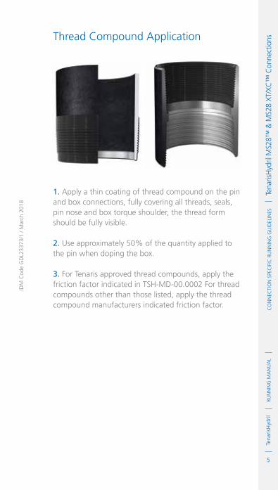
5
RUN
NIN
G M
AN
UA
LTe
naris
Hyd
ril
IDM
Cod
e G
DL2
3373
/1 /
Mar
ch 2
018
Co
NN
eCTI
oN
Spe
CIf
IC R
UN
NIN
G G
UID
eLIN
eS
Te
naris
Hyd
ril M
S28™
& M
S28
XT/
XC
™ C
onne
ctio
nsThread Compound Application
1. Apply a thin coating of thread compound on the pin and box connections, fully covering all threads, seals, pin nose and box torque shoulder, the thread form should be fully visible.
2. Use approximately 50% of the quantity applied to the pin when doping the box.
3. For Tenaris approved thread compounds, apply the friction factor indicated in TSH-MD-00.0002 For thread compounds other than those listed, apply the thread compound manufacturers indicated friction factor.

6
RUN
NIN
G M
AN
UA
LTe
naris
Hyd
rilC
oN
NeC
TIo
N S
peC
IfIC
RU
NN
ING
GU
IdeL
INeS
Tena
risH
ydril
MS2
8™ &
MS2
8 X
T/X
C™
Con
nect
ions Thread Lock Application
Connections must be clean and dry when applying thread lock.
1. Apply a thin coating of thread lock on 50% of the pin threads furthest from the pipe body.
2. Do not apply thread lock on the seal or torque shoulder.
3. Apply thread compound to the box seal and torque shoulder.
4. Apply the thread lock manufacturers indicated friction factor.

7
RUN
NIN
G M
AN
UA
LTe
naris
Hyd
ril
IDM
Cod
e G
DL2
3373
/1 /
Mar
ch 2
018
Co
NN
eCTI
oN
Spe
CIf
IC R
UN
NIN
G G
UID
eLIN
eS
Te
naris
Hyd
ril M
S28™
& M
S28
XT/
XC
™ C
onne
ctio
nsTorque Application
1. The use of computer make up analysis equipment is strongly recommended when assembling MS28™ and MS28 XT/XC™ connections.
2. Shoulder points for MS28™ and MS28 XT/XC™.
.Minimum 10% of optimum.
.Maximum 75% of optimum.
3. Reference torque should initially be set at 5% of optimum.
4. The dump valve should be set at optimum torque, verify correct operation on the pipe body prior to first make up.
5. Set the computer turns to 2 initially then adjust as necessary to attain good graph depiction.
6. Refer to the TenarisHydril running manual make up acceptance section for further explanation.
7. The computer make up profile for MS28™ and MS28 XT/XC™ should be similar to the ones below.
TOR
QU
E *
1000
ft-
lbs
0
0
1.7
3.4
5.0
6.7
0.23 0.45 0.68 0.91
MAX. 9680
TURNS
MIN. 8330
OPT 9000
MAX. SHL 6750
MIN. SHL 900

8
RUN
NIN
G M
AN
UA
LTe
naris
Hyd
rilC
oN
NeC
TIo
N S
peC
IfIC
RU
NN
ING
GU
IdeL
INeS
Tena
risH
ydril
MS2
8™ &
MS2
8 X
T/X
C™
Con
nect
ions
8. MS28™ and MS28 XT/XC™ connections of the same OD different weight are fully interchangeable.
9. MS28™ and MS28 XT/XC™ are not interchangeable with MS™ or MS XT/XC™.
10. If different weight or grade of connections are to be mixed apply the lower of the indicated make up torques.
11. MS28™ is interchangeable with MS28 XT/XC™.
12. If assembling MS28™ with MS28 XT/XC™ apply MS28™ torques. There will be a step at the interface of the torque shoulders.
13. Special clearance couplings require an adjustment to regular coupling torque, this should be available as an option when downloading the latest data sheet.
14. If the special clearance data sheet is unavailable adjust regular coupling torques as below:
.Apply minimum regular coupling torque as special clearance optimum torque.
.Apply 92.5% of minimum regular coupling torque as special clearance minimum torque.
TOR
QU
E *
1000
ft-
lbs
0
0
1.7
3.4
5.0
6.7
0.23 0.45 0.68 0.91
MAX. 9680
TURNS
MIN. 8330
OPT 9000
MAX. SHL 6750
MIN. SHL 900

9
RUN
NIN
G M
AN
UA
LTe
naris
Hyd
ril
IDM
Cod
e G
DL2
3373
/1 /
Mar
ch 2
018
Co
NN
eCTI
oN
Spe
CIf
IC R
UN
NIN
G G
UID
eLIN
eS
Te
naris
Hyd
ril M
S28™
& M
S28
XT/
XC
™ C
onne
ctio
ns.Apply 107.5% of minimum regular coupling torque as special clearance maximum torque.
ExAmpLE
.Regular coupling minimum torque = 10,000 ft.lb.Special clearance maximum torque = 10,750 ft.lb.Special clearance optimum torque = 10,000 ft.lb.Special clearance minimum torque = 9,250 ft.lb
Running 1. The use of a stabbing guide is strongly recommended.
2. The use of a weight compensator is strongly recommended for chrome, large OD or heavy pipe.
3. To avoid cross threading stab pipe in a smooth controlled fashion ensuring the pipe is vertical when doing so, continue to support and stabilise the pipe throughout the stabbing and make up operation.
4. Upon commencement of initial rotation use low RPM (5 RPM or below) in order to ensure the pipe has not cross threaded during stabbing.
5. If cross threading is evident, immediately reverse rotate the pipe, break out, clean and inspect both connections.
6. Maximum spin in speed should not exceed 15 RPM.
7. Apply power tong at low RPM (do not exceed 5 RPM) for final make up.
8. Walk chrome pipe all the way in to hand tight, then apply tong only for final make up.

10
RUN
NIN
G M
AN
UA
LTe
naris
Hyd
rilC
oN
NeC
TIo
N S
peC
IfIC
RU
NN
ING
GU
IdeL
INeS
Tena
risH
ydril
MS2
8™ &
MS2
8 X
T/X
C™
Con
nect
ions Pulling
1. Automatic stabbing system or stabber is highly recommended to maintain the pipe in a vertical position.
2. The use of a stabbing guide is recommended to assist in centralising the pin to prevent hang up.
3. A weight compensator is strongly recommended for chrome, large OD and heavy pipe.
4. Apply the back up tong jaw on the lower part, over the mill end of the coupling.
5. Apply power tong in low RPM (3-5 RPM) to break the connection, ensuring the pipe is stabilised during the break and spin out process.
6. Do not exceed 15 RPM during spin out.
7. Walk chrome pipe all the way out after initial break out.
8. Visual inspection is recommended to classify the thread condition. Any rejected connections should be clearly marked and segregated for further investigation.
9. Apply clean, dry thread protectors after applying storage compound on clean, dry connections.
10. Storage / thread compound should always be applied to connections post job, even rejects.

1
RUN
NIN
G M
AN
UA
LTe
naris
Hyd
rilC
oN
NeC
TIo
N S
peC
IfIC
RU
NN
ING
GU
IdeL
INeS
Tena
risH
ydril
3SB
™ C
onne
ctio
n
IdM
Cod
e G
dL2
3374
/1 /
Mar
ch 2
018
TenarisHydril3SB™ Connection
Scope
These guidelines apply specifically to the use of TenarisHydril 3SB™ connections. This document should be used in conjunction with the TenarisHydril Running Manual, which is the main document applicable to the running of all TenarisHydril premium connections.
References
.TenarisHydril Running Manual..Premium Connection Approved Thread Compounds TSH-MD-00.0002..Recommended guidelines for the field inspection of TenarisHydril connections, FSOG 13-005.
Equipment, Material & Documents
1. Verify the appropriate thread compound is available.
2. Refer to document TSH-MD-00.0002 for a list of compounds approved by Tenaris.
3. Latest version of the specific Product Data Sheet can be obtained from Tenaris web site. In case this is unavailable, request the data sheet from the local Technical Sales representative or [email protected].

2
RUN
NIN
G M
AN
UA
LTe
naris
Hyd
rilC
oN
NeC
TIo
N S
peC
IfIC
RU
NN
ING
GU
IdeL
INeS
Tena
risH
ydril
3SB
™ C
onne
ctio
n Pre-Running
1. Never move or handle pipe without the correct thread protectors securely in place.
2. Ensure connections are clean and free of all debris and / or contaminants, cleaning methods employed should conform to the recommendations contained within the TenarisHydril Running Manual.
3. Verify all pipe and accessories have genuine TenarisHydril manufactured connections.
4. Visually inspect thread and seal areas prior to running, ensuring no damage is evident.
5. Verify the compatibility of the 3SB™ pipe with accessories such as cement heads, safety valves, cross overs, etc.
6. Verify material grade of all accessories ensuring compatibility with main string.
7. Verify connection type: .4 ½" 3SB™ 13.5# and 21.6# have casing (5TPI) and Tubing (8TPI) variants, which are incompatible.
8. TenarisHydril 3SB™ is interchangeable with: .TenarisHydril 3SB™ / A.TenarisHydril 3SB ST™ .NK3SB / TS3SB
9. TenarisHydril 3SB™ is not interchangeable with:
.TenarisHydril New 3SB™.TenarisHydril 3SB SL™

3
RUN
NIN
G M
AN
UA
LTe
naris
Hyd
rilC
oN
NeC
TIo
N S
peC
IfIC
RU
NN
ING
GU
IdeL
INeS
Tena
risH
ydril
3SB
™ C
onne
ctio
n
IdM
Cod
e G
dL2
3374
/1 /
Mar
ch 2
018
Inspection
1. Inspection criteria for all TenarisHydril connections is as outlined in the Field Service Operative Guideline FSOG 13-005.
2. Pay particular attention to seal areas.
3. Ensure the pin nose has no tears, gouges or raised metal.
4. Ensure the pin and box torque shoulders have no dents, tears or raised material which would interfere with correct assembly.

4
RUN
NIN
G M
AN
UA
LTe
naris
Hyd
rilC
oN
NeC
TIo
N S
peC
IfIC
RU
NN
ING
GU
IdeL
INeS
Tena
risH
ydril
3SB
™ C
onne
ctio
n 3SB™ Configuration
Tubing 8 TPI ≤ 4 ½" 13.5#Casing 5 TPI ≥ 4 ½" 13.5#
SEAL
torquEShouLdEr

5
RUN
NIN
G M
AN
UA
LTe
naris
Hyd
ril
IDM
Cod
e G
DL2
3374
/1 /
Mar
ch 2
018
Co
NN
eCTI
oN
Spe
CIf
IC R
UN
NIN
G G
UID
eLIN
eS
Te
naris
Hyd
ril 3
SB™
Con
nect
ion Thread Compound Application
1. Apply a thin coating of thread compound on the pin and box connections, fully covering all threads, seals, pin nose and box torque shoulder, the thread form should be fully visible.
2. Use approximately 50% of the quantity applied to the pin when doping the box.
3. For Tenaris approved thread compounds, apply the friction factor indicated in TSH-MD-00.0002. For thread compounds other than those listed, apply the thread compound manufacturers indicated friction factor.

6
RUN
NIN
G M
AN
UA
LTe
naris
Hyd
rilC
oN
NeC
TIo
N S
peC
IfIC
RU
NN
ING
GU
IdeL
INeS
Tena
risH
ydril
3SB
™ C
onne
ctio
n Thread Lock Application
Connections must be clean and dry when applying thread lock
1. Apply a thin coating of thread lock on 50% of the pin threads furthest from the pipe body.
2. Do not apply thread lock on the seal or torque shoulder.
3. Apply thread compound to the box seal and torque shoulder.
4. Apply the thread lock manufacturers indicated friction factor.

7
RUN
NIN
G M
AN
UA
LTe
naris
Hyd
ril
IDM
Cod
e G
DL2
3374
/1 /
Mar
ch 2
018
Co
NN
eCTI
oN
Spe
CIf
IC R
UN
NIN
G G
UID
eLIN
eS
Te
naris
Hyd
ril 3
SB™
Con
nect
ion Torque Application
1. The use of computer make up analysis equipment is strongly recommended when assembling 3SB™ connections.
2. Shoulder points for 3SB™.
.Minimum 5% of optimum.
.Maximum 80% of optimum.
3. Reference torque should initially be set at 5% of optimum.
4. The dump valve should be set at optimum, verify correct operation on the pipe body prior to first make up.
5. Set the computer turns to 2 initially then adjust as necessary to attain good graph depiction.
6. Refer to the TenarisHydril Running Manual make up acceptance section for further explanation.
7. 3SB™ connections of the same weight and grade are fully interchangeable. See Pre-Running Section for exceptions.
8. If different weight or grade of connections are to be mixed apply the lower of the indicated make up torques.
9. The computer make up profile for 3SB™ should be similar to the ones below.

8
RUN
NIN
G M
AN
UA
LTe
naris
Hyd
rilC
oN
NeC
TIo
N S
peC
IfIC
RU
NN
ING
GU
IdeL
INeS
Tena
risH
ydril
3SB
™ C
onne
ctio
n
10. If 3SB™ is to be mixed with 3SB-ST™ the lower variant torque should be applied.
11. Special clearance couplings require an adjustment to regular coupling torque, this should be available as an option when downloading the latest data sheet.
12. If the special clearance data sheet is unavailable adjust regular coupling torques as below:
.Special Clearance Casing = 0.95 of regular torque..Special Clearance Tubing = 0.90 of regular torque.
TOR
QU
E *
1000
ft-
lbs
MAX. 7040
MAX. SHL 5120OPT 6400
0
0
1.7
3.4
5.1
6.8
0.16 0.32 0.48 0.65
TURNS
MIN. 5120
MIN. SHL 320
TOR
QU
E *
1000
ft-
lbs
MAX. 7040
MAX. SHL 5120OPT 6400
0
0
1.7
3.4
5.1
6.8
0.23 0.47 0.70 0.93
TURNS
MIN. 5120
MIN. SHL 320

9
RUN
NIN
G M
AN
UA
LTe
naris
Hyd
ril
IDM
Cod
e G
DL2
3374
/1 /
Mar
ch 2
018
Co
NN
eCTI
oN
Spe
CIf
IC R
UN
NIN
G G
UID
eLIN
eS
Te
naris
Hyd
ril 3
SB™
Con
nect
ion Running
1. The use of a stabbing guide is strongly recommended.
2. The use of a weight compensator is strongly recommended for chrome, large OD or heavy pipe.
3. To avoid cross threading stab pipe in a smooth controlled fashion ensuring the pipe is vertical when doing so, continue to support and stabilise the pipe throughout the stabbing and make up operation.
4. Upon commencement of initial rotation use low RPM (5 RPM or below) in order to ensure the pipe has not cross threaded during stabbing.
5. If cross threading is evident, immediately reverse rotate the pipe, completely disassemble, clean and inspect both connections.
6. Maximum spin in speed should not exceed 15 RPM.
7. Apply power tong at low RPM (do not exceed 5 RPM), for final make up.
8. Walk chrome pipe all the way in to hand tight, then apply tong only for final make up.

10
RUN
NIN
G M
AN
UA
LTe
naris
Hyd
rilC
oN
NeC
TIo
N S
peC
IfIC
RU
NN
ING
GU
IdeL
INeS
Tena
risH
ydril
3SB
™ C
onne
ctio
n Pulling
1. Automatic stabbing system or stabber is highly recommended to maintain the pipe in a vertical position.
2. The use of a stabbing guide is recommended to prevent hang up.
3. A weight compensator is strongly recommended for chrome, large OD or heavy pipe.
4. Apply the back up tong jaw on the lower part, over the mill end of the coupling.
5. Apply power tong in low RPM (3-5 RPM) to break the connection, ensuring the pipe is stabilised during the break and spin out process.
6. Do not exceed 15 RPM during spin out.
7. Walk chrome pipe all the way out after initial break.
8. Visual inspection is recommended to classify the thread condition. Any rejected connections should be clearly marked and segregated for further investigation.
9. Apply clean, dry thread protectors after applying storage compound on clean, dry connections.
10. Storage / thread compound should always be applied to connections post job, even rejects.

1
RUN
NIN
G M
AN
UA
LTe
naris
Hyd
rilC
oN
NeC
TIo
N S
peC
IfIC
RU
NN
ING
GU
IdeL
INeS
Tena
risH
ydril
pJd
™ C
onne
ctio
n
IdM
Cod
e G
dL2
3470
/1 /
Mar
ch 2
018
TenarisHydrilPJD™ Connection
Scope
These guidelines apply specifically to the use of TenarisHydril PJD™ connections. This document should be used in conjunction with the TenarisHydril Running Manual, which is the main document applicable to the running of all TenarisHydril premium connections.
References
.TenarisHydril Running Manual..Recommended guidelines for the field inspection of TenarisHydril connections, FSOG 13-005.
Equipment, Material & Documents
1. Verify the appropriate thread compound is available.
2. Refer to document TSH-MD-00.0002 for a list of compounds approved by Tenaris.
3. Latest version of the specific Product Data Sheet can be obtained from Tenaris website. In case this is unavailable, request the data sheet from the local Technical Sales representative or [email protected].
4. Ensure the single joint elevators to be used are the insert type and have the correct inserts in order to fully seat against the box upset.

2
RUN
NIN
G M
AN
UA
LTe
naris
Hyd
rilC
oN
NeC
TIo
N S
peC
IfIC
RU
NN
ING
GU
IdeL
INeS
Tena
risH
ydril
pJd
™ C
onne
ctio
n Pre-Running
1. Never move or handle pipe without the correct thread protectors securely in place.
2. Ensure connections are clean and free of all debris and / or contaminants, cleaning methods employed should conform to the recommendations contained within the TenarisHydril Running Manual.
3. Verify all pipe and accessories have genuine TenarisHydril manufactured connections.
4. Visually inspect threads and seal areas prior to running, ensuring no damage is evident.
5. Verify compatibility of the PJD™ connection with any accessories such as cement heads, safety valves, cross overs, etc.
6. Verify material grade of all accessories ensuring compatibility with main string.

3
RUN
NIN
G M
AN
UA
LTe
naris
Hyd
ril
IDM
Cod
e G
DL2
3470
/1 /
Mar
ch 2
018
Co
NN
eCTI
oN
Spe
CIf
IC R
UN
NIN
G G
UID
eLIN
eS
Te
naris
Hyd
ril p
JD™
Con
nect
ion PJD™ Configuration
Metal to Metal SealModified Buttress Thread
Seal
external
torque Shoulder
Internal
torque Shoulder

4
RUN
NIN
G M
AN
UA
LTe
naris
Hyd
rilC
oN
NeC
TIo
N S
peC
IfIC
RU
NN
ING
GU
IdeL
INeS
Tena
risH
ydril
pJd
™ C
onne
ctio
n Inspection
1. Inspection criteria for all Tenaris connections is as outlined in the Field Service Operative Guideline FSOG 13-005.
2. Pay particular attention to seal area.
3. Ensure there is no raised steel areas at both internal and external torque shoulders which could preclude correct make up.
4. Ensure the area between the last thread and the external torque shoulder of the pin has no tearing or raised areas which may contact the corresponding box area during make up.

5
RUN
NIN
G M
AN
UA
LTe
naris
Hyd
ril
IDM
Cod
e G
DL2
3470
/1 /
Mar
ch 2
018
Co
NN
eCTI
oN
Spe
CIf
IC R
UN
NIN
G G
UID
eLIN
eS
Te
naris
Hyd
ril p
JD™
Con
nect
ion Thread Compound Application
1. Apply thread compound to both pin and box threads, seals and torque shoulders.
2. Do not over apply, thread profile should be clearly visible.

6
RUN
NIN
G M
AN
UA
LTe
naris
Hyd
rilC
oN
NeC
TIo
N S
peC
IfIC
RU
NN
ING
GU
IdeL
INeS
Tena
risH
ydril
pJd
™ C
onne
ctio
n
TOR
QU
E
0
0
500
1000
1500
2000
2500
3000
0.2 0.4 0.6 0.8 1 1.2 1.4 1.6 1.8 2 2.2 2.4 2.6 2.8 3
TURNS
MAX 2350
MIN 1800
OPT 2000
MAX SHL 1500
MIN SHL 300
Torque Application
1. The use of computer make up analysis equipment is strongly recommended when assembling PJD™ connections.
2. Shoulder points for PJD™
.Minimum 15% of optimum torque.
.Maximum 75% of optimum torque.
3. Reference torque should initially be set at 5% of optimum.
4. The dump valve should be set at optimum, verify correct operation on the pipe body prior to first make up.
5. Set the computer turns to 2 initially then adjust as necessary to attain good graph depiction.
6. Refer to the TenarisHydril Running Manual, make up acceptance section for further explanation.
7. The computer make up profile for PJD™ connections should be similar to the one below.

7
RUN
NIN
G M
AN
UA
LTe
naris
Hyd
ril
IDM
Cod
e G
DL2
3470
/1 /
Mar
ch 2
018
Co
NN
eCTI
oN
Spe
CIf
IC R
UN
NIN
G G
UID
eLIN
eS
Te
naris
Hyd
ril p
JD™
Con
nect
ion 8. PJD™ connection is interchangeable for same size /
weight, if mixing weight / grade apply the lower torque values of the two connections.
Running 1. The use of a stabbing guide is strongly recommended.
2. The use of slip type elevators is strongly recommended.
3. Never use drill pipe elevators to run or pull PJD™.
4. Use insert type single joint elevators to pick up or lay down pipe from the rig floor, ensure the inserts are of the correct size and seat evenly on the box upset.
5. The use of a weight compensator is strongly recommended for chrome pipe.
6. To avoid cross threading stab pipe in a smooth controlled fashion ensuring the pipe is vertical when doing so, continue to support and stabilise the pipe throughout the stabbing and make up operation.
7. Upon commencement of initial rotation use low RPM (5 RPM or below) in order to ensure the pipe has not cross threaded during stabbing.
8. If cross threading is evident immediately reverse rotate the pipe, completely disassemble, clean and inspect both connections.
9. Maximum spin in speed should not exceed 15 RPM.
10. Apply power tong at low RPM (do not exceed 5 RPM) for final make up.

8
RUN
NIN
G M
AN
UA
LTe
naris
Hyd
rilC
oN
NeC
TIo
N S
peC
IfIC
RU
NN
ING
GU
IdeL
INeS
Tena
risH
ydril
pJd
™ C
onne
ctio
n 11. Walk chrome pipe all the way in to hand tight, then apply tong only for final make up.
12. Apply the tongs to the pipe body, do not grip the pin or box connections.
Pulling
1. Automatic stabbing system or stabber is highly recommended to maintain the pipe in a vertical position.
2. The use of a stabbing guide is recommended to assist in centralising the pin to prevent hang up.
3. The use of slip type elevators is strongly recommended.
4. A weight compensator is strongly recommended for chrome pipe.
5. Apply the back up tong jaw on the pipe body, never grip the box connections.
6. Apply power tong in low RPM (3-5 RPM) to break the connection, ensuring the pipe is stabilised during the break out process.
7. Do not exceed 15 RPM during spin out.
8. Walk chrome pipe all the way out after initial break.
9. Visual inspection is recommended to classify the thread condition. Any rejected connections should be clearly marked and segregated for further investigation.
10. Apply clean, dry thread protectors after applying storage compound on clean, dry connections.
11. Storage / thread compound should always be applied to connections post job, even rejects.

1
RUN
NIN
G M
AN
UA
LTe
naris
Hyd
rilC
oN
NeC
TIo
N S
peC
IfIC
RU
NN
ING
GU
IdeL
INeS
Tena
risH
ydril
pH
6™ /
pH4™
/ C
S® C
onne
ctio
ns
IdM
Cod
e G
dL2
3376
/1 /
Mar
ch 2
018
TenarisHydrilPH6™ / PH4™ / CS® Connections
Scope
These guidelines apply specifically to the use of TenarisHydril PH6™ / PH4™ / CS® connections. This document should be used in conjunction with the TenarisHydril Running Manual, which is the main document applicable to the running of all TenarisHydril premium connections.
References
.TenarisHydril Running Manual..Premium Connection Approved Thread Compounds TSH-MD-00.0002..Recommended guidelines for the field inspection of TenarisHydril connections, FSOG 13-005.
Equipment, Material & Documents
1. Verify the appropriate thread compound is available.
2. Refer to document TSH-MD-00.0002 for a list of compounds approved by Tenaris.
3. Latest version of the specific Product Data Sheet can be obtained from Tenaris web site. In case this is unavailable, request the data sheet from the local Technical Sales Representative or [email protected].

2
RUN
NIN
G M
AN
UA
LTe
naris
Hyd
rilC
oN
NeC
TIo
N S
peC
IfIC
RU
NN
ING
GU
IdeL
INeS
Tena
risH
ydril
pH
6™ /
pH4™
/ C
S® C
onne
ctio
ns
Pre-Running
1. Never move or handle pipe without the correct thread protectors securely in place.
2. Ensure connections are cleaned and free of all debris and / or contaminants, cleaning methods employed should conform to the recommendations contained within the TenarisHydril Running Manual.
3. Visually inspect threads and seal areas prior to running, ensuring no damage is evident.
4. Verify the connections to be assembled are genuine TenarisHydril manufactured connections.
5. Verify compatibility of the PH6™ / PH4™ / CS® connection with any accessories such as pup joints, cross overs, safety valves, etc.
6. Verify material grade of all accessories ensuring compatibility with main string.

3
RUN
NIN
G M
AN
UA
LTe
naris
Hyd
ril
IDM
Cod
e G
DL2
3376
/1 /
Mar
ch 2
018
Co
NN
eCTI
oN
Spe
CIf
IC R
UN
NIN
G G
UID
eLIN
eS
Te
naris
Hyd
ril p
H6™
/ pH
4™ /
CS®
Con
nect
ions
PH6™ / PH4™ / CS® Configuration
PH6™ = 6 TPIPH4™ = 4 TPICS® = 8 TPI ≤ 4 ½"CS® = 4 TPI ≥ 5"
ExtErnal SEal /
torquE ShouldEr
IntErnal SEal
IntErmEdIatE
torquE ShouldEr
IntErnal SEal
CorroSIon BarrIEr
(CB) optIon

4
RUN
NIN
G M
AN
UA
LTe
naris
Hyd
rilC
oN
NeC
TIo
N S
peC
IfIC
RU
NN
ING
GU
IdeL
INeS
Tena
risH
ydril
pH
6™ /
pH4™
/ C
S® C
onne
ctio
ns
Inspection
1. Inspection criteria for all TenarisHydril connections is as outlined in the Field Service Operative Guideline FSOG 13-005.
2. Pay particular attention to seal areas.
3. Ensure the cylindrical areas before and after the seals have no tears, gouges or raised metal.
4. Ensure the intermediate torque shoulder has no dents, tears or raised material which would interfere with correct assembly.
Thread Compound Application
For CarBon StEEl pIpE
1. Apply a thin coating of thread compound on the full pin end only, threads, seals and pin nose, the thread form should be clearly visible.
CarBon StEEl
ChromE matErIal

5
RUN
NIN
G M
AN
UA
LTe
naris
Hyd
ril
IDM
Cod
e G
DL2
3376
/1 /
Mar
ch 2
018
Co
NN
eCTI
oN
Spe
CIf
IC R
UN
NIN
G G
UID
eLIN
eS
Te
naris
Hyd
ril p
H6™
/ pH
4™ /
CS®
Con
nect
ions
2. Do not apply running compound to the box end.
3. Thread compound should be cleaned from the box of carbon steel if received 'rig ready'.
For ChromE matErIal pIpE
1. Apply a thin coating of thread compound on both pin and box ensuring all threads, seals and pin nose are completely covered.
2. Do not over dope the connections, a thin even layer covering all surfaces is adequate, the thread form should be fully visible.
3. Use approximately 50% of the quantity applied to the pin when doping the box.
4. Do not apply the manufacturers indicated friction factor.
Torque Application
1. The use of computer make up analysis equipment is strongly recommended when assembling PH6™ / PH4™ / CS® connections in chrome material.
2. There are no defined shoulder points for PH6™ /PH4™ / CS®, however a shoulder point must be in evidence.
3. Shoulder point must be lower than minimum make up torque.
4. Reference torque should be set at zero.

6
RUN
NIN
G M
AN
UA
LTe
naris
Hyd
rilC
oN
NeC
TIo
N S
peC
IfIC
RU
NN
ING
GU
IdeL
INeS
Tena
risH
ydril
pH
6™ /
pH4™
/ C
S® C
onne
ctio
ns
5. The dump valve should be set at optimum torque, verify correct operation on the pipe body prior to first make up.
6. Set the computer turns to 1 initially then adjust as necessary to attain good graph depiction.
7. Refer to the TenarisHydril running manual make up acceptance section for further explanation.
8. The computer make up profile for PH6™ / PH4™ / CS® should be similar to the one below.
TOR
QU
E (f
t-lb
s)
3.131
0
2000
4000
6000
8000
10000
11990
7.131
TURNS
9. PH6™ / PH4™ / CS® connections have limited same size different weight interchange capability, refer to TenarisHydril premium connections catalogue for interchange capability.
10. PH6™ / PH4™ / CS® are not interchangeable with each other.
11. If different weight or grade of connections are to be mixed apply the lower of the indicated make up torques.

7
RUN
NIN
G M
AN
UA
LTe
naris
Hyd
ril
IDM
Cod
e G
DL2
3376
/1 /
Mar
ch 2
018
Co
NN
eCTI
oN
Spe
CIf
IC R
UN
NIN
G G
UID
eLIN
eS
Te
naris
Hyd
ril p
H6™
/ pH
4™ /
CS®
Con
nect
ions
Running 1. The use of a stabbing guide is strongly recommended.
2. The use of a weight compensator is strongly recommended for chrome pipe.
3. Slip type elevators are strongly recommended, never use drill pipe elevators to run or pull PH6™, PH4™ or CS® connections.
4. To avoid cross threading stab pipe in a smooth controlled fashion ensuring the pipe is vertical when doing so, continue to support and stabilise the pipe throughout the stabbing and make up operation.
5. Upon commencement of initial rotation use low RPM (5 RPM or below) in order to ensure the pipe has not cross threaded during stabbing.
6. If cross threading is evident, immediately reverse rotate the pipe, completely disassemble, clean and inspect both connections.
7. Maximum spin in speed should not exceed 15 RPM.
8. Apply power tong at low RPM (do not exceed 5 RPM) for final make up.
9. Tong jaws must always be placed on the pipe body and never on the connection OD.
10. Walk chrome pipe all the way in to hand tight, then apply tong only for final make up.

8
RUN
NIN
G M
AN
UA
LTe
naris
Hyd
rilC
oN
NeC
TIo
N S
peC
IfIC
RU
NN
ING
GU
IdeL
INeS
Tena
risH
ydril
pH
6™ /
pH4™
/ C
S® C
onne
ctio
ns
Pulling
1. Automatic stabbing system or stabber is highly recommended to maintain the pipe in a vertical position.
2. The use of a stabbing guide is recommended to assist in centralizing the pin to prevent hang up.
3. The use of a weight compensator is strongly recommended for chrome pipe.
4. The use of slip type elevators is strongly recommended.
5. Apply the back up tong jaw on the pipe body, do not grip the OD of the connections.
6. Apply power tong in low RPM (3-5 RPM) to break the connection, ensuring the pipe is stabilized during the break and spin out process.
7. Do not exceed 15 RPM during spin out.
8. Walk chrome pipe fully out after initial break out.
9. Visual inspection is recommended to classify the thread condition. Any rejected connections should be clearly marked and segregated for further investigation.
10. Apply clean, dry thread protectors after applying storage compound on clean, dry connections.
11. Storage / thread compound should always be applied to connections post job, even rejects.

1
RUN
NIN
G M
AN
UA
LTe
naris
Hyd
rilC
oN
NeC
TIo
N S
peC
IfIC
RU
NN
ING
GU
IdeL
INeS
Tena
risX
p® B
uttr
ess
Con
nect
ionTenarisXP® Buttress
Connection
Scope
These guidelines apply specifically to the use of TenarisXP® Buttress connections. This document should be used in conjunction with the TenarisHydril Running Manual, which is the main document applicable to the running of all TenarisHydril premium connections.
TenarisXP® Buttress connection is a Buttress threaded connection with a positive stop torque shoulder, compatible with API Buttress connection (restricted capability, dependent upon what is required of the connections when assembled).
References
.TenarisHydril Running Manual..Premium Connection Approved Thread Compounds TSH-MD-00.0002..TenarisXP® Buttress Buck on Instructions TSH-MD-25.0003..API Specification 5B..API Recommended Practice 5C1..API Recommended Practice 5A5.
Equipment, Material & Documents
1. Verify the appropriate thread compound is available for this connection.
2. Refer to document TSH-MD-00.0002 for a list of thread compounds approved by Tenaris.
IDM
Cod
e G
DL0
0338
/4 /
Mar
ch 2
018

2
RUN
NIN
G M
AN
UA
LTe
naris
Hyd
rilC
oN
NeC
TIo
N S
peC
IfIC
RU
NN
ING
GU
IdeL
INeS
Tena
risX
p® B
uttr
ess
Con
nect
ion 3. Latest version of the specific Product Data Sheet
can be obtained from Tenaris web site. In case it is not available, request the data sheet from the local Technical Sales representative or [email protected].
Pre-Running
1. Never move or handle pipe without the correct thread protectors securely in place.
2. Ensure connections are clean and free of all debris and / or contaminants, cleaning methods employed should conform to the recommendations contained within the TenarisHydril Running Manual.
3. Verify all pipe and accessories have genuine TenarisHydril manufactured connections.
4. Visually inspect threads, pin nose and couplings prior to running, ensuring no damage is evident.
5. Verify the compatibility of the TenarisXP® Buttress connection with accessories such as cement heads, safety valves, cross overs, etc.
6. Verify material grade of all accessories ensuring compatibility with main string.
7. If TenarisXP® Buttress Seal Ring (SR) variant is being run ensure the correct type and quantity of seal rings are available.

3
RUN
NIN
G M
AN
UA
LTe
naris
Hyd
rilC
oN
NeC
TIo
N S
peC
IfIC
RU
NN
ING
GU
IdeL
INeS
Tena
risX
p® B
uttr
ess
Con
nect
ion
IdM
Cod
e G
dL0
0338
/4 /
Mar
ch 2
018
Inspection
1. Visual inspection guidelines as outlined in API RP 5A5 should be applied.
2. Pay particular attention to pin nose and box torque shoulder ensuring there is no raised material which may preclude correct make up.
3. Ensure threads are clean and free of any debris or contamination.
4. Check the condition of the seal ring of TenarisXP® Buttress-SR variant.
5. Ensure the seal ring has no cuts, gouges or tears.
6. Ensure the seal ring is correctly seated with no proud areas which may cause the ring to be displaced during make up.
7. TenarisXP® Buttress connection will be identifiable by a 1" wide Magenta band painted round the coupling OD opposite the grade identification bands.
8. TenarisXP® Buttress with a regular API coupling OD will have two magenta paint bands.
TXP® Buttress Coupling.

4
RUN
NIN
G M
AN
UA
LTe
naris
Hyd
rilC
oN
NeC
TIo
N S
peC
IfIC
RU
NN
ING
GU
IdeL
INeS
Tena
risX
p® B
uttr
ess
Con
nect
ion TenarisXP® Buttress Configuration
Positive stoP
torque shoulder
seal ring
variant
Buttress
thread Profile

5
RUN
NIN
G M
AN
UA
LTe
naris
Hyd
rilC
oN
NeC
TIo
N S
peC
IfIC
RU
NN
ING
GU
IdeL
INeS
Tena
risX
p® B
uttr
ess
Con
nect
ion
IdM
Cod
e G
dL0
0338
/4 /
Mar
ch 2
018
TenarisXP® Buttress Seal Ring Variant
1. The Seal Ring (SR) variant of TenarisXP® Buttress connection is designed to enhance the sealing capability of the original connection.
2. If the seal ring variant is ordered they will be delivered directly from the mill with the SR installed.
3. Seal rings are designed to be used once, therefore they must be replaced after every make up.
4. Prior to make up ensure the seal ring is undamaged and securely installed.
5. When replacing a seal ring ensure the groove is undamaged, clean and free of debris.
6. Only seal rings specifically manufactured for TenarisXP® Buttress connection can be used, ensure these are not mixed with other types of seal rings, such as corrosion barrier rings.
7. TenarisXP® Buttress seal rings are yellow therefore easily identifiable.
8. Install the seal ring as indicated in the TenarisHydril Running Manual FGL and CB® options section.
9. Ensure the seal ring is seated into the groove completely to prevent thread compound extruding the ring as the connection makes up.
10. Seal rings for any given size are compatible with connections of different weight.
11. Protectors specifically designed for the seal ring variant must be used in order to prevent damage and /or displacement of seal ring from the coupling groove.

6
RUN
NIN
G M
AN
UA
LTe
naris
Hyd
rilC
oN
NeC
TIo
N S
peC
IfIC
RU
NN
ING
GU
IdeL
INeS
Tena
risX
p® B
uttr
ess
Con
nect
ion
12. As can be seen in the above photograph, when correctly installed the seal ring sits evenly and concentrically within the groove.
seal ring

7
RUN
NIN
G M
AN
UA
LTe
naris
Hyd
rilC
oN
NeC
TIo
N S
peC
IfIC
RU
NN
ING
GU
IdeL
INeS
Tena
risX
p® B
uttr
ess
Con
nect
ion
IdM
Cod
e G
dL0
0338
/4 /
Mar
ch 2
018
Thread compound application
1. Apply thread running compound to both pin and box ends, covering all threads and shoulder areas.
2. The compound should be applied as a continuous even film round the entire circumference of the connection, the thread form should be clearly visible.
3. When applying thread compound to the TenarisXP® Buttress Seal Ring variant, ensure the seal ring is securely seated to prevent thread compound being pushed under the ring which may cause it to dislodge during assembly.
4. For Tenaris approved thread compounds, apply the friction factor indicated in TSH-MD-00.0002. For thread compounds other than those listed, apply the thread compound manufacturers indicated friction factor.

8
RUN
NIN
G M
AN
UA
LTe
naris
Hyd
rilC
oN
NeC
TIo
N S
peC
IfIC
RU
NN
ING
GU
IdeL
INeS
Tena
risX
p® B
uttr
ess
Con
nect
ion Thread Lock Application
Connections must be clean and dry when applying thread lock.
1. Apply thread lock to the 50% of the pin threads furthest from the pipe body.
2. Apply the thread lock manufacturers indicated friction factor.
Torque Application
1. Torques for TenarisXP® Buttress connection should always be taken from the latest TenarisHydril product data sheet.
2. The use of torque turn computer equipment is not necessary to make up TenarisXP® Buttress connection.
3. If torque turn computer equipment is used the guidelines indicated in the Blue® and Legacy Series Make up Acceptance section are applicable.
4. If using torque turn computer equipment the make up graphs should look similar to the ones below.

9
RUN
NIN
G M
AN
UA
LTe
naris
Hyd
rilC
oN
NeC
TIo
N S
peC
IfIC
RU
NN
ING
GU
IdeL
INeS
Tena
risX
p® B
uttr
ess
Con
nect
ion
IdM
Cod
e G
dL0
0338
/4 /
Mar
ch 2
018
TOP SHD
TOR
QU
E
0.0 1.0
0100020003000400050006000700080008932
2.0 3.0 4.0 5.00 6.0 7.0 8.0 9.0 10.0 11.0
TURNS
OPT 7400MAX 8120
TOP SHD
TOR
QU
E
6.6 7.0
0100020003000400050006000700080008932
7.4 7.8 8.2 8.6 9.0 9.4 9.8 10.2 10.6
TURNS
OPT 7400MAX 8120
5. Shoulder point should be clearly observed on the torque turn graph.
Shoulder point should fall between reference torque and minimum make up torque parameters. However, should shoulder torque exceed minimum make up torque then the connection can still be accepted if the following conditions are met: 1) final make up torque is within minimum and maximum make up torque values, 2) shoulder point is clearly visible, and 3) the graph profile meets Running Manual guidelines.
Running 1. To avoid cross threading stab pipe in a smooth controlled fashion ensuring the pipe is vertical when doing so, continue to support and stabilise the pipe throughout the stabbing and make up operation.

10
RUN
NIN
G M
AN
UA
LTe
naris
Hyd
rilC
oN
NeC
TIo
N S
peC
IfIC
RU
NN
ING
GU
IdeL
INeS
Tena
risX
p® B
uttr
ess
Con
nect
ion 2. Upon commencement of initial rotation use low
RPM (5 RPM or below) in order to ensure the pipe has not cross threaded during stabbing.
3. If cross threading is evident, immediately reverse rotate the pipe slowly, break out and inspect both connections.
4. Maximum spin in speed should not exceed 15 RPM.
5 Apply power tong at low RPM (do not exceed 5 RPM) for final make up.
6. The make up criteria for TenarisXP® Buttress connection is the attainment of optimum torque along with the coupling face final position. As in the assembly of API Buttress there is a triangle stamped on the pin end which is used as a visual verification of correct assembly of the connection. Final positon of the coupling face after make up should be anywhere from the base of the triangle to 70% below the apex. On average the coupling face should finish 25% of the height of the triangle stamp after application of the recommended make up torque (75% from Apex). The coupling face should never exceed 30% of the triangle height at final make up. If it does, break out the connection and inspect for deformation of pin nose bevel and box torque shoulder, if none is evident repeat doping and make up process. See diagram 1 below:

11
RUN
NIN
G M
AN
UA
LTe
naris
Hyd
rilC
oN
NeC
TIo
N S
peC
IfIC
RU
NN
ING
GU
IdeL
INeS
Tena
risX
p® B
uttr
ess
Con
nect
ion
IdM
Cod
e G
dL0
0338
/4 /
Mar
ch 2
018
MINIMUM FINISH POINT
MAXIMUM FINISH POINT 0.262" (6.66 mm) FROM APEX
COUPLING FACE
0.375"
1.
24" x 1" White locator striPe aBove aPi triangle
7. To make up API Buttress connections, API 5B states; 'The face of the coupling advances to within one full thread turn of the base of the triangle stamp for minimum power tight make up and to the apex of the triangle for maximum make up'.

12
RUN
NIN
G M
AN
UA
LTe
naris
Hyd
rilC
oN
NeC
TIo
N S
peC
IfIC
RU
NN
ING
GU
IdeL
INeS
Tena
risX
p® B
uttr
ess
Con
nect
ion Interchange Capability
Compatibility of TenarisXP® Buttress connection and non Tenaris manufactured API Buttress is completely dependent on what the user requires from any given mix of API and TenarisXP® Buttress connections.
The make up criteria with resulting torque and compression capabilities of any given combination are indicated in Table 1.
Table 1
TenarisXP®
Buttress
TenarisXP® Buttress
APIButtress
APIButtress
-
-
Yes
No
TenarisXP®
Buttress
APIButtress
TenarisXP® Buttress
TenarisXP® Buttress
TenarisXP®
Buttress
APIButtress
TenarisXP®
Buttress
APIButtress*
TenarisXP®
Buttress
APIButtress
TenarisXP®
Buttress
APIButtress
PIN eNd
TenarisXP® Buttress and API Buttress Interchange Capability
TeNArIs MANufACTured
BoX eNd AsseMBlY CrITerIA
Torque & CoMPressIoN
CAPABIlITY
(*) When assemBling a non tenaris manufactured aPi
Buttress Pin into a tenarisxP® Buttress Box the finish Point of
the couPling face should not exceed the triangle Base.
Certain API Buttress box accessories are manufactured with a shoulder, these are not TenarisXP® Buttress specification. Best practice in each case is to measure the distance from the shoulder of the accessory to the box face and mark this make up loss length alongside the triangle of the TenarisXP® Buttress connection to be assembled. Any discrepancy in length of the box to that of the maximum make up point of the TenarisXP® Buttress will then be identifiable, thereafter the decision of what make up criteria to apply can be

13
RUN
NIN
G M
AN
UA
LTe
naris
Hyd
rilC
oN
NeC
TIo
N S
peC
IfIC
RU
NN
ING
GU
IdeL
INeS
Tena
risX
p® B
uttr
ess
Con
nect
ion
IdM
Cod
e G
dL0
0338
/4 /
Mar
ch 2
018
discussed and agreed. The criteria applied will be dependent upon what is required of the application. There may be a situation where, to achieve the torque capability of TenarisXP® Buttress, the accessory face will have to finish higher up the TenarisXP® Buttress triangle in order to achieve shoulder contact. However the coupling face should never exceed the triangle apex, even if shoulder contact is not achieved.
Pulling
1. Automatic stabbing system or stabber is highly recommended to maintain the pipe in a vertical position.
2. The use of a weight compensator is highly recommended for large OD and heavy weight pipe.
3. Apply the back up tong jaw low on the coupling (over mill end section of the coupling), leaving the field end free.
4. Apply power tong in low RPM (3-5 RPM) to break out the connection, ensuring the pipe is stabilized during the break out process.
5. Maximum spin out speed should not exceed 15 RPM.
6. Visual inspection is recommended to classify the thread condition. Any rejected connections should be clearly marked and segregated for further investigation.
7. If the Seal Ring variant, it may be advisable to remove the seal rings as the connections are pulled.
8. Apply clean dry thread protectors after applying storage compound on the connections.
9. Storage / thread compound should always be applied to connections post job, even rejects.

14
RUN
NIN
G M
AN
UA
LTe
naris
Hyd
rilC
oN
NeC
TIo
N S
peC
IfIC
RU
NN
ING
GU
IdeL
INeS
Tena
risX
p® B
uttr
ess
Con
nect
ion

1
RUN
NIN
G M
AN
UA
LTe
naris
Hyd
rilC
oN
NeC
TIo
N S
peC
IfIC
RU
NN
ING
GU
IdeL
INeS
ApI
But
tres
s C
onne
ctio
ns
IdM
Cod
e G
dL0
0382
/2 /
Mar
ch 2
018
API Buttress Connections
Scope
These guidelines apply specifically to the use of API Buttress connections. This document is based on API 5C1 standard which is the main document applicable for this connection.
References
.API RP 5C1: Recommended practice for care and use of casing and tubing..API RP 5A3: Recommended practice on thread compounds for casing, tubing and line pipe..ISO 13678: Petroleum and natural gas industries -Evaluation and testing of thread compounds for use with casing, tubing, line pipe and drill stem elements.API RP 5A5: Field inspection of new casing, tubing, and plain-end drill pipe..API RP 5B1: Gauging and inspection of casing, tubing and line pipe threads..API 5B: Specification for Threading, Gauging and Thread Inspection of Casing, Tubing and Line Pipe Threads.
Equipment, Material & Documents
1. Verify API modified thread compound is available.
2. If other compound is to be used, ensure it provides adequate lubrication and sealability. Refer to API RP 5A3 or ISO 13678 for further details.

2
RUN
NIN
G M
AN
UA
LTe
naris
Hyd
rilC
oN
NeC
TIo
N S
peC
IfIC
RU
NN
ING
GU
IdeL
INeS
ApI
But
tres
s C
onne
ctio
ns Pre-Running
1. If drifting the connections at the rig site it is recommended to do so from box to pin end.
2. Ensure connections are cleaned and free of all debris and / or contaminants.
3. Use high pressure water with detergent to clean the connections, it is not advisable to use an oil based solvent which may leave a residue on the threads.
4. Never move or handle pipe without the correct thread protectors securely in place.
5. Visually inspect threads prior to running, ensuring no damage is evident.
6. Verify compatibility of the API Buttress pipe with any accessories such as pup joints.
7. Verify material grade of all accessories ensuring compatibility with main string.
Inspection
1. Inspection criteria for all API connections is as outlined in API RP 5A5.
2. Ensure the complete thread area has no tears, gouges or raised metal.
3. Black crested threads within the complete thread area must not exceed 25% of the circumference of two (2) threads.
4. Complete thread length is indicated in API RP 5B1.

3
RUN
NIN
G M
AN
UA
LTe
naris
Hyd
ril
IDM
Cod
e G
DL0
0382
/2 /
Mar
ch 2
018
Co
NN
eCTI
oN
Spe
CIf
IC R
UN
NIN
G G
UID
eLIN
eS
A
pI B
uttr
ess
Con
nect
ions
TRIANGLE
RUNOUT
LENGTH TO THE TRIANGLE BASE
TOTAL THREAD LENGTH
COMPLETE THREADLENGTH
5. Ensure the pin and box have no dents, tears or raised material which would interfere with correct assembly.
6. Any gouge or tear which traverses from the coupling OD to the face is cause for rejection.
API Buttress Configuration
3° 10°
PIN
BOXBUTTRESS GENERAL

4
RUN
NIN
G M
AN
UA
LTe
naris
Hyd
rilC
oN
NeC
TIo
N S
peC
IfIC
RU
NN
ING
GU
IdeL
INeS
ApI
But
tres
s C
onne
ctio
ns
Thread Compound Application
1. Apply a thin coating of thread compound on pin and box connections, fully covering all threads.
2. The thread form should be fully visible.
DOPE
ThrEaDCorreCt doping
1. The triangle is located at the base of a 1" by 24" white stripe for ease of identification.

5
RUN
NIN
G M
AN
UA
LTe
naris
Hyd
ril
IDM
Cod
e G
DL0
0382
/2 /
Mar
ch 2
018
Co
NN
eCTI
oN
Spe
CIf
IC R
UN
NIN
G G
UID
eLIN
eS
A
pI B
uttr
ess
Con
nect
ionsThread Lock Application
1. Connections must be clean and dry when applying thread lock.
2. Apply a thin coating of thread lock on 50% of the pin threads furthest from the pipe body.
3. Do not apply thread compound to pin or box.
Make Up
1. API Buttress connection is designed to be made up to a final position, there is no final torque specified.
2. Make up acceptance criteria is defined based on the relative position of the coupling face compared to the triangle stamped on the pin end:
.Minimum Make up: One full thread turn before triangle base.
.Maximum Make up: Triangle apex.

6
RUN
NIN
G M
AN
UA
LTe
naris
Hyd
rilC
oN
NeC
TIo
N S
peC
IfIC
RU
NN
ING
GU
IdeL
INeS
ApI
But
tres
s C
onne
ctio
ns
0.375" (3/8")(9.525 mm)
TRIANGLE
0.200" (5.08 mm)TOLERANCE
MAKE UPADMISSIBLEZONE
3. There is no torque specification for API Buttress however torque values required to reach an acceptable make up tend to be similar within the same batch of pipe.
4. In order to determine make up torque for the string to be run:
.Make up the first 15 joints to the base of the stamped triangle, taking note of the required torque for each joint.
.Calculate the average torque.
.Use the average torque to make up the string.
.Ensure all make ups are acceptable by checking the coupling face position within the triangle.
5. It may occur that during the make up, the coupling rotates on the mill end. This can be allowed provided the coupling face on the mill end does not exceed the apex of the triangle stamped on the mill end pin.

7
RUN
NIN
G M
AN
UA
LTe
naris
Hyd
ril
IDM
Cod
e G
DL0
0382
/2 /
Mar
ch 2
018
Co
NN
eCTI
oN
Spe
CIf
IC R
UN
NIN
G G
UID
eLIN
eS
A
pI B
uttr
ess
Con
nect
ions
Running
1. To avoid cross threading stab pipe in a smooth controlled fashion ensuring the pipe is vertical when doing so, continue to support and stabilise the pipe throughout the stabbing and make up operation.
2. Upon commencement of initial rotation use low RPM (5 RPM or below) in order to ensure the pipe has not cross threaded during stabbing.
3. If cross threading is evident, immediately reverse rotate the pipe slowly, break out and inspect both connections.
4. Maximum spin in speed should not exceed 15 RPM.
FIELD END MILL END

8
RUN
NIN
G M
AN
UA
LTe
naris
Hyd
rilC
oN
NeC
TIo
N S
peC
IfIC
RU
NN
ING
GU
IdeL
INeS
ApI
But
tres
s C
onne
ctio
ns Pulling 1. Automatic stabbing system or stabber is highly recommended to maintain the pipe in a vertical position.
2. Apply the back up tong jaw on the lower part, over mill end, of the coupling.
3. Apply power tong in low RPM (3-5 RPM) to break out the connection, ensuring the pipe is stabilised during the break and spin out process.
4. Visual inspection is recommended to classify the thread condition. Any rejected connections should be clearly marked and segregated for further investigation.
5. Apply clean, dry thread protectors after applying storage compound on clean, dry connections.
6. Storage / thread compound should always be applied to connections post job, even rejects.

1
RUN
NIN
G M
AN
UA
LTe
naris
Hyd
rilC
oN
NeC
TIo
N S
peC
IfIC
RU
NN
ING
GU
IdeL
INeS
ApI
8 R
ound
Con
nect
ions
IdM
Cod
e G
dL0
0389
/2 /
Mar
ch 2
018
API 8 Round Connections
Scope
These guidelines apply specifically to the use of API 8RD (STC, LTC, EUE, NUE) connections. This document is based on API RP 5C1 which is the main document applicable for this connection.
References
.API RP 5C1: Recommended Practice for care and use of casing and tubing, latest edition..API 5A3: Recommended practice on thread compounds for casing, tubing and line pipe..SO 13678: Petroleum and natural gas industries -Evaluation and testing of thread compounds for use with casing, tubing, line pipe and drill stem elements..API RP 5A5: Field inspection of new casing, tubing, and plain-end drill pipe..API RP 5B1: Gauging and inspection of casing, tubing, and line pipe threads..API 5B: Specification for Threading, Gauging and Thread Inspection of Casing, Tubing and Line Pipe Threads.
Equipment, Material & Documents
1. Verify API modified thread compound is available.
2. If other compound is to be used, ensure it provides adequate lubrication and sealability. Refer to API RP 5A3 or ISO 13678 for further details.

2
RUN
NIN
G M
AN
UA
LTe
naris
Hyd
rilC
oN
NeC
TIo
N S
peC
IfIC
RU
NN
ING
GU
IdeL
INeS
ApI
8 R
ound
Con
nect
ions Pre-Running
1. If drifting the connections at the rig site it is recommended to do so from box to pin end.
2. Ensure connections are cleaned and free of all debris and / or contaminants.
3. Use high pressure water with detergent to clean the connections, it is not advisable to use an oil based solvent which may leave a residue on the threads.
4. Never move or handle pipe without the correct thread protectors securely in place.
5. Visually inspect threads prior to running, ensuring no damage is evident.
6. Verify compatibility of the API 8RD pipe with any accessories such as pup joints.
7. Verify material grade of all accessories ensuring compatibility with main string.
Inspection
1. Inspection criteria for all API connections is as outlined in API RP 5A5.
2. Ensure the complete thread area has no tears, gouges or raised metal.
3. Black crested threads within the complete thread length area must not exceed 25% of the circumference of two (2) threads.
4. Complete thread length is indicated in API RP 5B1.
5. Any gouge or tear which traverses from the coupling OD to the face is cause for rejection.

3
RUN
NIN
G M
AN
UA
LTe
naris
Hyd
ril
IDM
Cod
e G
DL0
0389
/2 /
Mar
ch 2
018
Co
NN
eCTI
oN
Spe
CIf
IC R
UN
NIN
G G
UID
eLIN
eS
A
pI 8
Rou
nd C
onne
ctio
nsThread Compound Application
1. Apply a thin coating of thread compound on pin and box connections, fully covering all threads.
2. The thread form should be fully visible.
3. During make up an API 8RD connection has high interference between flanks, leading to high friction. Hence, it is very important to apply dope correctly on both ends to avoid galling. Due to connection configuration the thread crests and roots are not in contact, there is a gap to be filled by the running compound.

4
RUN
NIN
G M
AN
UA
LTe
naris
Hyd
rilC
oN
NeC
TIo
N S
peC
IfIC
RU
NN
ING
GU
IdeL
INeS
ApI
8 R
ound
Con
nect
ions Thread Lock Application
1. Connections must be clean and dry when applying thread lock.
2. Apply a thin coating of thread lock on 50% of the pin threads furthest from the pipe body.
3. Do not apply thread compound to pin or box.

5
RUN
NIN
G M
AN
UA
LTe
naris
Hyd
ril
IDM
Cod
e G
DL0
0389
/2 /
Mar
ch 2
018
Co
NN
eCTI
oN
Spe
CIf
IC R
UN
NIN
G G
UID
eLIN
eS
A
pI 8
Rou
nd C
onne
ctio
nsMake Up
Make up process and torque values are referenced in API RP 5C1.
Make Up with OptiMUM tOrqUe
To achieve correct make up, apply optimum torque. After reaching this value, it is necessary to verify the box face position reaches the vanish point of the pin, with a tolerance of ± two threads from the box face.
Make Up with MaxiMUM tOrqUe
If after applying optimum torque there are several threads visible beyond the box face, apply 25% more torque to reach an acceptable final position. If after applying the additional torque there is more than three threads exposed, the joint must be rejected as questionable.
Vanish pOint nO Visible
threads

6
RUN
NIN
G M
AN
UA
LTe
naris
Hyd
rilC
oN
NeC
TIo
N S
peC
IfIC
RU
NN
ING
GU
IdeL
INeS
ApI
8 R
ound
Con
nect
ions Make Up with MiniMUM tOrqUe
If the box face surpasses thread vanish point by more than two (2) thread turns without attaining 75% of optimum torque, the joint should be treated as questionable and rejected.
Casing sizes (≥ 4 ½") will have a 3/8" (0.375") equilateral triangle stamped at the pin end, this triangle is solely an aid to establish the location of the thread vanish point and is not a basis for make up acceptance / rejection.
TOR
QU
E
OPTIMUM
MAXIMUM
MAKE-UPACCEPTABLEZONE
2 threads out 2 threads inside
MINIMUM

7
RUN
NIN
G M
AN
UA
LTe
naris
Hyd
ril
IDM
Cod
e G
DL0
0389
/2 /
Mar
ch 2
018
Co
NN
eCTI
oN
Spe
CIf
IC R
UN
NIN
G G
UID
eLIN
eS
A
pI 8
Rou
nd C
onne
ctio
nsPulling 1. Automatic stabbing system or stabber is highly recommended to maintain the pipe in a vertical position.
2. Apply the back up tong jaw on the lower part, over the mill end of the coupling.
3. Apply power tong in low RPM (3-5 RPM) to break out the connection, ensuring the pipe is stabilised during the break and spin out process.
4. Visual inspection is recommended to classify the thread condition. Any rejected connections should be clearly marked and segregated for further investigation.
5. Apply clean, dry thread protectors after applying storage compound on clean, dry connections.
6. Storage / thread compound should always be applied to connections post job, even rejects.

8
RUN
NIN
G M
AN
UA
LTe
naris
Hyd
rilC
oN
NeC
TIo
N S
peC
IfIC
RU
NN
ING
GU
IdeL
INeS
ApI
8 R
ound
Con
nect
ions

1
RUN
NIN
G M
AN
UA
LTe
naris
Hyd
rilC
oN
NeC
TIo
N S
peC
IfIC
RU
NN
ING
GU
IdeL
INeS
Tena
ris S
eC™
Con
nect
ion
IdM
Cod
e G
dL2
3377
/1 /
Mar
ch 2
018
SEC Connection
Scope
These guidelines apply specifically to the use of SEC connections. This document should be used in conjunction with the TenarisHydril Running Manual, which is the main document applicable to the running of all TenarisHydril premium connections.
References
.TenarisHydril Running Manual..Premium Connection Approved Thread Compounds TSH-MD-00.0002..Recommended guidelines for the field inspection of TenarisHydril connections, FSOG 13-005.
Equipment, Material & Documents
1. Verify the appropriate thread compound is available.
2. Refer to document TSH-MD-00.0002 for a list of compounds approved by Tenaris.
3. Latest version of the specific Product Data Sheet can be obtained from the local Tenaris Technical Sales representative or [email protected].

2
RUN
NIN
G M
AN
UA
LTe
naris
Hyd
rilC
oN
NeC
TIo
N S
peC
IfIC
RU
NN
ING
GU
IdeL
INeS
Tena
ris S
eC™
Con
nect
ion Pre-Running
1. Never move or handle pipe without the correct thread protectors securely in place.
2. Ensure connections are clean and free of all debris and / or contaminants, cleaning methods employed should conform to the recommendations contained within the TenarisHydril Running Manual.
3. Verify all pipe and accessories have genuine TenarisHydril manufactured connections.
4. Visually inspect thread and seal areas prior to running, ensuring no damage is evident.
5. Verify the compatibility of the SEC connection with accessories such as cement heads, safety valves, cross overs, etc.
6. Verify material grade of all accessories ensuring compatibility with main string.

3
RUN
NIN
G M
AN
UA
LTe
naris
Hyd
ril
IDM
Cod
e G
DL2
3377
/1 /
Mar
ch 2
018
Co
NN
eCTI
oN
Spe
CIf
IC R
UN
NIN
G G
UID
eLIN
eS
Te
naris
SeC
™ C
onne
ctio
nInspection
1. Inspection criteria for all TenarisHydril connections is as outlined in the Field Service Operative Guideline FSOG 13-005.
2. Pay particular attention to seal areas.
3. Ensure the pin nose has no tears, gouges or raised metal.
4. Ensure the pin and box torque shoulders have no dents, tears or raised material which could interfere with correct assembly.

4
RUN
NIN
G M
AN
UA
LTe
naris
Hyd
rilC
oN
NeC
TIo
N S
peC
IfIC
RU
NN
ING
GU
IdeL
INeS
Tena
ris S
eC™
Con
nect
ion SEC Configuration
Tubing 2 3/8" – 2 7/8" = 8 TPI Tubing 3 1/2" – 4 1/2" = 6 TPI Casing 5" – 13 3/8" = 5 TPI

5
RUN
NIN
G M
AN
UA
LTe
naris
Hyd
ril
IDM
Cod
e G
DL2
3377
/1 /
Mar
ch 2
018
Co
NN
eCTI
oN
Spe
CIf
IC R
UN
NIN
G G
UID
eLIN
eS
Te
naris
SeC
™ C
onne
ctio
n
Modified BTC
Thread
TuBing Seal
CaSing Seal
Torque Shoulder

6
RUN
NIN
G M
AN
UA
LTe
naris
Hyd
rilC
oN
NeC
TIo
N S
peC
IfIC
RU
NN
ING
GU
IdeL
INeS
Tena
ris S
eC™
Con
nect
ion Thread Compound Application
1. Apply a thin coating of thread compound on the pin and box connections, fully covering all threads, seals, pin nose and box torque shoulder, the thread form should be fully visible.
2. Use approximately 20% of the quantity applied to the pin when doping the box.
3. For Tenaris approved thread compounds, apply the friction factor indicated in TSH-MD-00.0002. For thread compounds other than those listed, apply the thread compound manufacturers indicated friction factor.
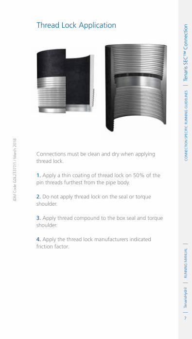
7
RUN
NIN
G M
AN
UA
LTe
naris
Hyd
ril
IDM
Cod
e G
DL2
3377
/1 /
Mar
ch 2
018
Co
NN
eCTI
oN
Spe
CIf
IC R
UN
NIN
G G
UID
eLIN
eS
Te
naris
SeC
™ C
onne
ctio
nThread Lock Application
Connections must be clean and dry when applying thread lock.
1. Apply a thin coating of thread lock on 50% of the pin threads furthest from the pipe body.
2. Do not apply thread lock on the seal or torque shoulder.
3. Apply thread compound to the box seal and torque shoulder.
4. Apply the thread lock manufacturers indicated friction factor.

8
RUN
NIN
G M
AN
UA
LTe
naris
Hyd
rilC
oN
NeC
TIo
N S
peC
IfIC
RU
NN
ING
GU
IdeL
INeS
Tena
ris S
eC™
Con
nect
ion Torque Application
1. The use of computer make up analysis equipment is strongly recommended when assembling SEC connections.
2. Shoulder points for SEC connections are determined as a percentage of final applied torque.
Final Torque – Shoulder TorqueFinal Torque
x 100 = Delta Torque
3. The table above indicates the acceptable minimum and maximum delta torque percentages.
4. Reference torque should initially be set at 5% of optimum torque.
5. The dump valve should be set at optimum torque, verify correct operation on the pipe body prior to first make up.
6. Set the computer turns to 2 initially then adjust as necessary to attain good graph depiction.
7. Refer to the TenarisHydril running manual make up acceptance section for further explanation.
8. The computer make up profile for SEC connections should be similar to the ones below.
Tubing
Casing
95%
100%
95%
30%
30%
40%
MAxIMUMMINIMUM
ST / FR
GR
ST / FR / GR
SHOULDER TORqUES

9
RUN
NIN
G M
AN
UA
LTe
naris
Hyd
ril
IDM
Cod
e G
DL2
3377
/1 /
Mar
ch 2
018
Co
NN
eCTI
oN
Spe
CIf
IC R
UN
NIN
G G
UID
eLIN
eS
Te
naris
SeC
™ C
onne
ctio
n
TOR
QU
E *
1000
ft-
lbs
0
0
1.7
3.4
5.0
6.7
0.23 0.45 0.68 0.91
MAX. 9680
TURNS
MIN. 8330
OPT 9000
TOR
QU
E *
1000
ft-
lbs
0
0
1.7
3.4
5.0
6.7
0.23 0.45 0.68 0.91
MAX. 9680
TURNS
MIN. 8330
OPT 9000
10. SEC ST / FR / GR tubing connections with the same OD are interchangeable.
11. If different weight or grade of connections are to be mixed apply the lower of the indicated make up torques.
9. SEC connections of the same same OD different weight are fully interchangeable.

10
RUN
NIN
G M
AN
UA
LTe
naris
Hyd
rilC
oN
NeC
TIo
N S
peC
IfIC
RU
NN
ING
GU
IdeL
INeS
Tena
ris S
eC™
Con
nect
ion Running
1. The use of a stabbing guide is strongly recommended.
2. The use of a weight compensator is strongly recommended for chrome, large OD or heavy pipe.
3. To avoid cross threading stab pipe in a smooth controlled fashion ensuring the pipe is vertical when doing so, continue to support and stabilise the pipe throughout the stabbing and make up operation.
4. Upon commencement of initial rotation use low RPM (5 RPM or below) in order to ensure the pipe has not cross threaded during stabbing.
5. If cross threading is evident, immediately reverse rotate the pipe, break out, clean and inspect both connections.
6 Maximum spin in speed should not exceed 15 RPM.
7. Apply power tong at low RPM (do not exceed 5 RPM) for final make up.
8. Walk chrome pipe all the way in to hand tight, then apply tong only for final make up.
11
RUN
NIN
G M
AN
UA
LTe
naris
Hyd
ril
IDM
Cod
e G
DL2
3377
/1 /
Mar
ch 2
018
Co
NN
eCTI
oN
Spe
CIf
IC R
UN
NIN
G G
UID
eLIN
eS
Te
naris
SeC
™ C
onne
ctio
nPulling 1. Automatic stabbing system or stabber is highly recommended to maintain the pipe in a vertical position.
2. The use of a stabbing guide is recommended to assist in centralising the pin to prevent hang up.
3. A weight compensator is strongly recommended for chrome, large OD and heavy pipe.
4. Apply the back up tong jaw on the lower part, over the mill end, of the coupling.
5. Apply power tong in low RPM (3-5 RPM) to break the connection, ensuring the pipe is stabilised during the break and spin out process.
6. Do not exceed 15 RPM during spin out.
7. Walk chrome pipe all the way out after initial break out.
8. Visual inspection is recommended to classify the thread condition, any rejected connections should be clearly marked and segregated for further investigation.
9. Apply clean, dry thread protectors after applying storage compound on clean, dry connections.
10. Storage / thread compound should always be applied to connections post job, even rejects.

12
RUN
NIN
G M
AN
UA
LTe
naris
Hyd
rilC
oN
NeC
TIo
N S
peC
IfIC
RU
NN
ING
GU
IdeL
INeS
Tena
ris S
eC™
Con
nect
ion


www.tenaris.com/tenarishydril


