24
TAVOLO SOLAIO TF QUICK USER INFORMATION MANUALE D’USO TABLE SLAB SYSTEM TF QUICK
TAVOLO SOLAIOTF QUICK
USER INFORMATION
MANUALE D’USO
TABLESLAB SYSTEM
TF QUICK

SAFETY WARNINGS
• The respect of these instructions does not exempt from compliance with all safety regulations in force in the country where you use the system.
• These instructions are intended for users of TF products and systems. Each one must be aware of the contents of this manual; in case they have difficulties in reading the same, the employer has to provide education of the same
• The User’s Manual instructions must always be available at the workplace for all operators
• This manual, even if used in order to draw up a Method Statement, will not substitute it, and the Method Statement will remain an important and unavoidable site document, responsibility of the client.
• Information and illustrations contained herein are relative to only the system in question, and therefore not exhaustive about the overall security; always refer to the applicable health and safety regulations in the area of use of the equipment
• In relation to flow, configuration, installation, use and dismantling of equipment TF Strictly obey all instructions contained herein; failure to comply with them may result in serious accidents to people, as well as extensive property damage
• Take every precaution consequently due to the climatic conditions of the site (i.e. in case of rain and/or ice to provide anti-slip measures etc.)
• Periodically verify, especially after severe weather conditions, any connection, wedge or any other connecting element, in order to avoid any possible system instability and consequent accidents
AVVERTENZE SULLA SICUREZZA
• Il rispetto delle presenti istruzioni non esime dall’osservanza di tutte le norme sulla sicurezza vigenti nel paese dove si utilizzi il Sistema in oggetto
• Le istruzioni qui riportate sono rivolte agli utilizzatori di prodotti e siste-mi The Formwork. Ognuno di essi deve essere a conoscenza del con-tenuto di questo manuale; in caso abbiano difficoltà nella lettura dello stesso, il datore di lavoro deve provvedere all’istruzione degli stessi
• Le istruzioni d’uso devono sempre essere disponibili sul luogo di lavoro per tutti gli operatori
• Il presente manuale, pur potendo essere utilizzato per la redazione di un piano operativo utilizzandone le informazioni utili, non lo sostituisce, ed il piano resta comunque obbligo del cliente ed in capo al datore di lavoro degli operatori.
• Informazioni ed illustrazioni qui contenute sono relative al solo sistema in oggetto, e quindi non esaustive riguardo la sicurezza generale; fare sempre riferimento alle norme vigenti per la si-curezza sul territorio di utilizzo delle attrezzature
• Rispettare scrupolosamente ogni indicazioni qui contenuta rela-tivamente a portate, configurazioni, montaggio, uso e smontag-gio delle attrezzature TF; la mancata osservanza delle stesse può essere causa di incidenti gravi per le persone, nonchè di gravi danni alle cose.
• Adottare ogni dovuta precauzione conseguentemente alle condizioni climatiche di cantiere (p.e. in caso di pioggia e/o ghiaccio prevedere misure anti-scivolo etc..)
• Controllare sempre, ed in special modo dopo eventi climatici particolari, ogni giunzione, cuneo o qualsivoglia elemento di fissaggio/collegamento, onde prevenire possibili instabilità del sistema e conseguenti incidenti
DESCRIZIONE DEL SISTEMA
CARATTERISTICHE TECNICHE
GRIGLIA DEL SISTEMA
ASSEMBLAGGIO & UTILIZZO
DIMENSIONAMENTO
COMPENSAZIONI
MODULI PERIMETRALI
TRASLAZIONE DEL SISTEMA
TRASPORTO & STOCCAGGIO
LISTA COMPONENTI
SYSTEM DESCRIPTION
TECHNICAL FEATURES
SYSTEM GRIDS
ASSEMBLING & USE
SYSTEM DIMENSIONING
CLOSURES
EDGE MODULES
SYSTEM SHIFTING
TRANSPORT & STORAGE
ITEMS LIST
5
6
9
10
11
12
13
14
17
18
5
6
9
10
11
12
13
14
17
18
S U M M A R Y S O M M A R I O
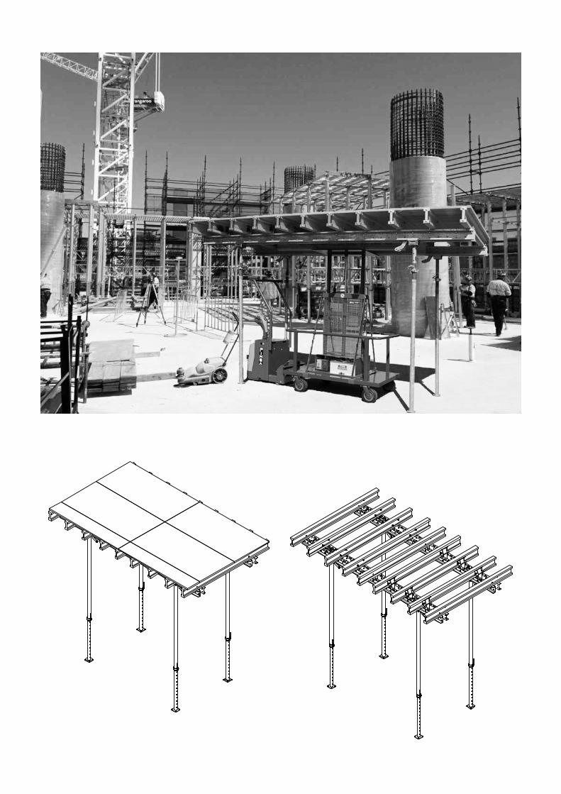
TF Quick is the Slab Table System wich guarantees the maximum results in terms of safety, speed and productivity realizing any typology of slabs.
STANDARD GRID- 2.50 x 4.00 m- 2.50 x 5.00 m- 2.00 x 4.00 m- 2.00 x 5.00 m
HIGH WORK LOADS: the standard system configuration (2 props x waling) work with total safety up to 60cm slab thickness (depending on tables size); when slab thickness exceed the 60cm, other than apply “intermediate” auxiliary props among Swivel Heads (with props to be chosen between 20 or 30 kN), tables can be combined with TF Alu-Prop or TF2 Load Bearing Towers, increasing noticeably the “whole” system loadability.
EASY TO USE: composed by steel walings “double U” 140 as primary and H20 beams as secondary, it’s supported by steel props connected to the swivel heads, so that only the props fixing is needed before having the system working on site. Workforce resources and slab pourings cycle time outstanding reduction are the most considerable system benefits.
EASY SHIFTING: thanks to the Shifting Trolley one only operator is needed for the system shifting; thanks to the swivel table head, even in presence of perimeteral obstacles, the uplifting to next level is quick and safe; Lifting Straps (when shifting platform are present), or Lifting Forks give always the possibility for a fast and safe vertical shifting.
SAFETY: the system avoid dangerous and time consuming works with risks of falling, with use of edge protection (as hand rails) assembled simultaneously to the props fixing done on the ground, thus avoiding to repeat same operations further and at hight with consequent bigger risks.Stable, strong, user-friendly big surfaces are the working areas for the formwork staff. System’s general concept is to always execute operations once and from the ground!
SYSTEM DESCRIPTION
TF Quick è l sistema Tavolo Solaio che garantisce i massimi risultati in termini di sicurezza, velocità e produttività per svariate tipologie costruttive
GRIGLIA STANDARD- 2,50 x 4,00 m- 2,50 x 5,00 m- 2,00 x 4,00 m- 2.00 x 5.00 m
ELEVATI CARICHI DI ESERCIZIO: I formati standard di Sistema operano in tutta sicurezza sino a 60cm di spessore solaio (a seconda delle dimensioni tavoli); in caso di spessori superiori, oltre al poter fissure puntelli ausiliari “intermedi” tra le Teste a ribalta (puntelli da 20 o 30 Kn di portata), I Tavoli possono essere combinati con I sistemi TF Alu-prop o Torri di carico TF 2, aumentando così notevolmente la portata del sistema.
FACILE DA USARE: composto da travi primarie in correnti in acciaio a “doppia U” 140 e travi secondarie H20, è supportato da puntelli in acciaio in accordo ad eurocodice EN 1065 fissati alle teste a ribalta, ed è quindi necessario il solo fissaggio dei puntelli per avere il sistema pronto all’uso. La sostanziale riduzione della forza lavoro e dei tempi di realizzazione dei solai sono I principali vantaggi del Sistema.
TRASLAZIONE SEMPLIFICATA: grazie al carrello di traslazione è necessario 1 solo operatore per lo spostamento alla fase di lavoro successiva; la Testa a Ribalta permette un’agevole traslazione verticale anche in presenza di ostacoli come muri perimetrali, permettendo il passaggio del tavolo completo dei puntelli attraverso le aperture; Cinghie di sollevamento (in presenza di piattaforme di sbarco) e forche garantiscono una traslazione verticale veloce e sicura in ogni ambito.
SICUREZZA: il sistema evita pericolose e lunghe lavorazioni con rischio di caduta dall’alto mediante l’utilizzo di protezioni perimetrali (come i parapetti di Sistema) montate contemporaneamente al fissaggio dei puntelli, il tutto eseguito “a terra”, evitando così continue ripetizioni di lavorazioni rischiose. Stabili e sicure, le grandi superfici del sistema sono l’area di lavoro per lo staff di cantiere. Il principio base del sistema è di eseguire il maggior numero di operazioni di assemblaggio una sola volta e da terra!
DESCRIZIONE DEL SISTEMA
5
TABLE SLAB SYSTEM TF QUICK | TAVOLO SOLAIO TF QUICK
6
COVERING SHEET | MANTO di RIVESTIMENTO
SECONDARY BEAMS | TRAVI SECONDARIE
PRIMARY BEAMS | TRAVI PRIMARIE
CARATTERISTICHE TECNICHE
DESCRIZIONE TECNICA: Di seguito i componenti del sistema in dettaglio
TECHNICAL FEATURES:
TECHNICAL DESCRIPTION: Hereunder the system components in detail
1
1
2
2
3
3
4
4
5
5
6
6
7
7
8
8
A A
B B
C C
D D
E E
F F
G G
H H
SHEET 1 OF 1
DRAWN
CHECKED
QA
MFG
APPROVED
Gianluca 09/12/2015
DWG NO
Trasporto e Stoccaggio Tavoli-1
TITLE
SIZE
30 x 42 (pollici)SCALE
REV
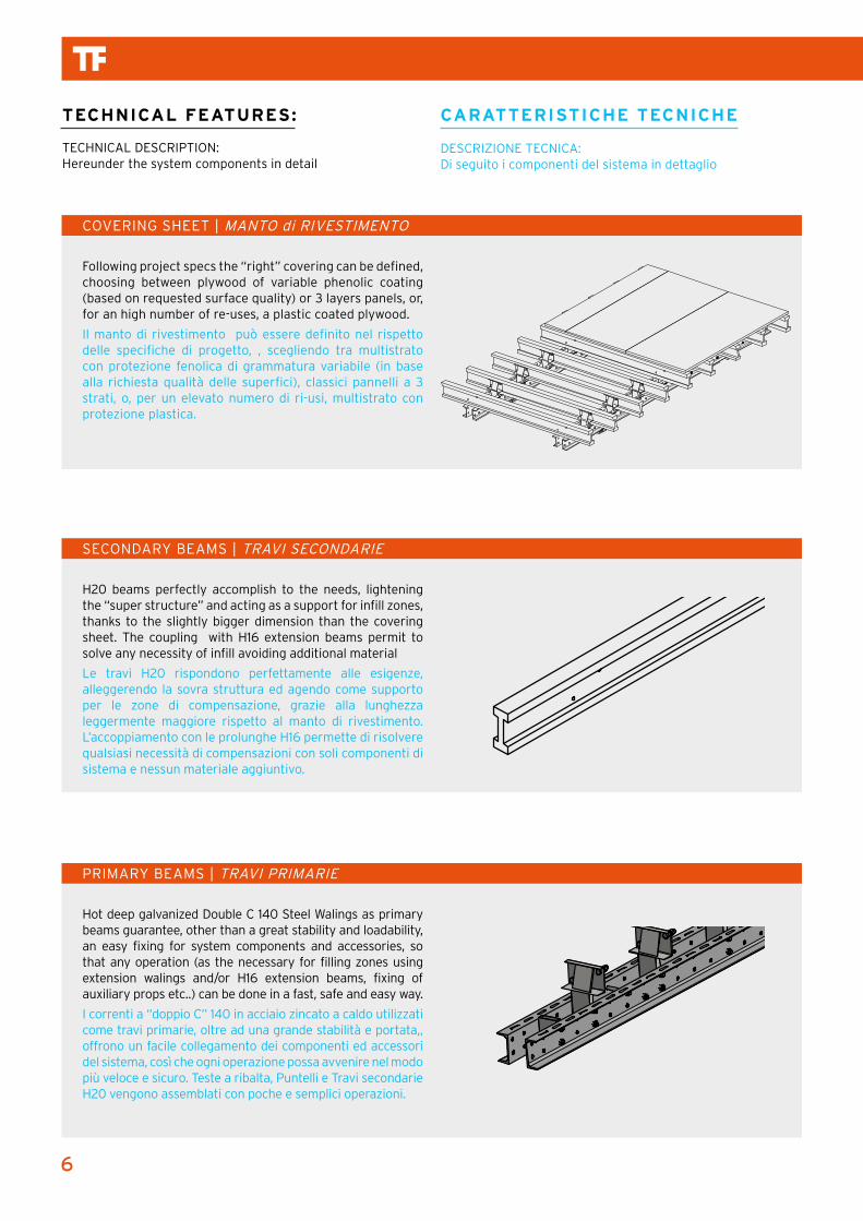
Following project specs the “right” covering can be defined, choosing between plywood of variable phenolic coating (based on requested surface quality) or 3 layers panels, or, for an high number of re-uses, a plastic coated plywood.
Il manto di rivestimento può essere definito nel rispetto delle specifiche di progetto, , scegliendo tra multistrato con protezione fenolica di grammatura variabile (in base alla richiesta qualità delle superfici), classici pannelli a 3 strati, o, per un elevato numero di ri-usi, multistrato con protezione plastica.
H20 beams perfectly accomplish to the needs, lightening the “super structure” and acting as a support for infill zones, thanks to the slightly bigger dimension than the covering sheet. The coupling with H16 extension beams permit to solve any necessity of infill avoiding additional material
Le travi H20 rispondono perfettamente alle esigenze, alleggerendo la sovra struttura ed agendo come supporto per le zone di compensazione, grazie alla lunghezza leggermente maggiore rispetto al manto di rivestimento. L’accoppiamento con le prolunghe H16 permette di risolvere qualsiasi necessità di compensazioni con soli componenti di sistema e nessun materiale aggiuntivo.
Hot deep galvanized Double C 140 Steel Walings as primary beams guarantee, other than a great stability and loadability, an easy fixing for system components and accessories, so that any operation (as the necessary for filling zones using extension walings and/or H16 extension beams, fixing of auxiliary props etc..) can be done in a fast, safe and easy way.
I correnti a “doppio C” 140 in acciaio zincato a caldo utilizzati come travi primarie, oltre ad una grande stabilità e portata,, offrono un facile collegamento dei componenti ed accessori del sistema, così che ogni operazione possa avvenire nel modo più veloce e sicuro. Teste a ribalta, Puntelli e Travi secondarie H20 vengono assemblati con poche e semplici operazioni.
1
1
2
2
3
3
4
4
5
5
6
6
7
7
8
8
A A
B B
C C
D D
E E
F F
G G
H H
SHEET 1 OF 1
DRAWN
CHECKED
QA
MFG
APPROVED
Gianluca 09/12/2015
DWG NO
Trasporto e Stoccaggio Tavoli-1
TITLE
SIZE
30 x 42 (pollici)SCALE
REV
1
1
2
2
3
3
4
4
5
5
6
6
7
7
8
8
A A
B B
C C
D D
E E
F F
G G
H H
SHEET 1 OF 1
DRAWN
CHECKED
QA
MFG
APPROVED
Gianluca 09/12/2015
DWG NO
Trasporto e Stoccaggio Tavoli-1
TITLE
SIZE
30 x 42 (pollici)SCALE
REV
7
TABLE SLAB SYSTEM TF QUICK | TAVOLO SOLAIO TF QUICK
SWIVEL HEAD | TESTA A RIBALTA
CASTING PHASE - FIXED HEAD | FASE DI ARMO - TESTA FISSATA
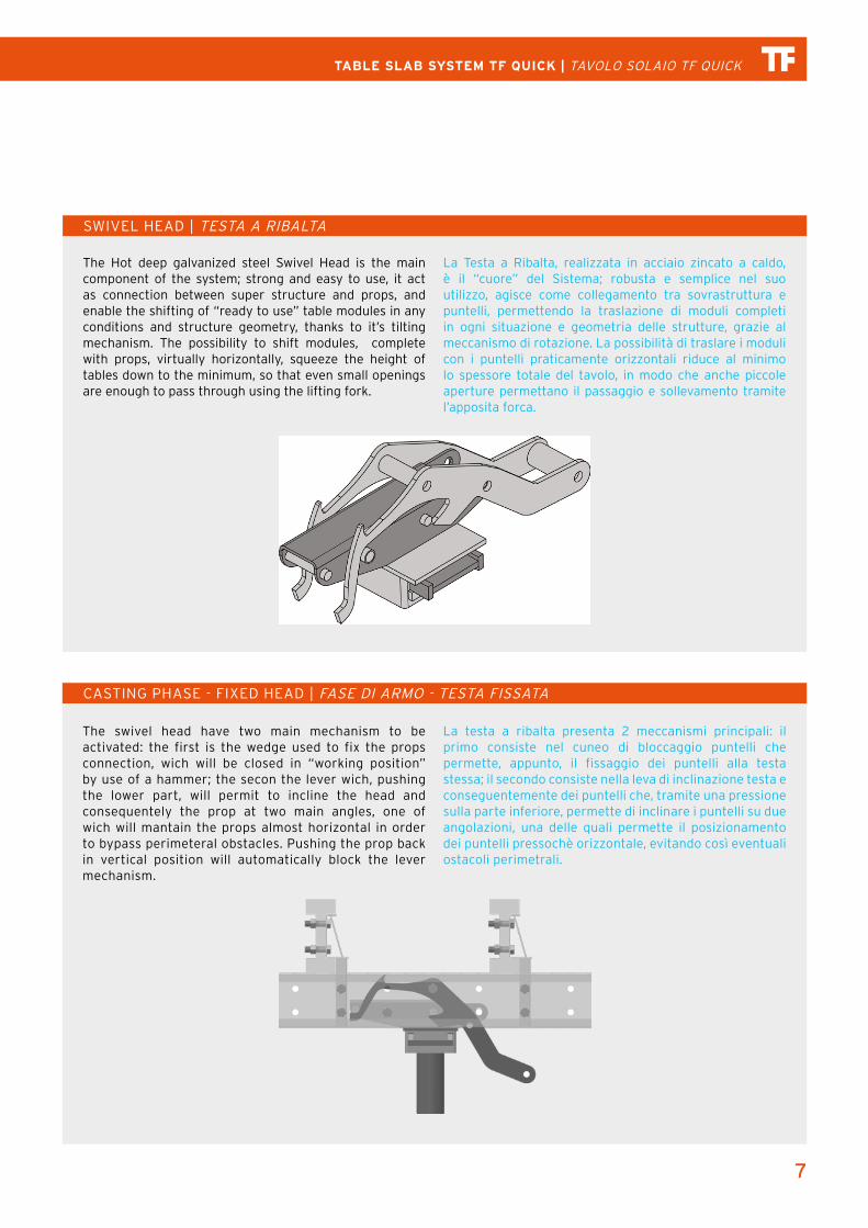
The Hot deep galvanized steel Swivel Head is the main component of the system; strong and easy to use, it act as connection between super structure and props, and enable the shifting of “ready to use” table modules in any conditions and structure geometry, thanks to it’s tilting mechanism. The possibility to shift modules, complete with props, virtually horizontally, squeeze the height of tables down to the minimum, so that even small openings are enough to pass through using the lifting fork.
La Testa a Ribalta, realizzata in acciaio zincato a caldo, è il “cuore” del Sistema; robusta e semplice nel suo utilizzo, agisce come collegamento tra sovrastruttura e puntelli, permettendo la traslazione di moduli completi in ogni situazione e geometria delle strutture, grazie al meccanismo di rotazione. La possibilità di traslare i moduli con i puntelli praticamente orizzontali riduce al minimo lo spessore totale del tavolo, in modo che anche piccole aperture permettano il passaggio e sollevamento tramite l’apposita forca.
The swivel head have two main mechanism to be activated: the first is the wedge used to fix the props connection, wich will be closed in “working position” by use of a hammer; the secon the lever wich, pushing the lower part, will permit to incline the head and consequentely the prop at two main angles, one of wich will mantain the props almost horizontal in order to bypass perimeteral obstacles. Pushing the prop back in vertical position will automatically block the lever mechanism.
La testa a ribalta presenta 2 meccanismi principali: il primo consiste nel cuneo di bloccaggio puntelli che permette, appunto, il fissaggio dei puntelli alla testa stessa; il secondo consiste nella leva di inclinazione testa e conseguentemente dei puntelli che, tramite una pressione sulla parte inferiore, permette di inclinare i puntelli su due angolazioni, una delle quali permette il posizionamento dei puntelli pressochè orizzontale, evitando così eventuali ostacoli perimetrali.
8
SHIFTING PHASE - HEAD’S TILTING | FASE DI TRASLAZIONE – INCLINAZIONE TESTA
TF STEEL PROPS | PUNTELLI TF ACCIAIO
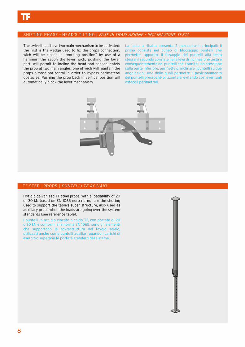
Hot dip galvanized TF steel props, with a loadability of 20 or 30 kN based on EN 1065 euro norm, are the shoring used to support the table’s super structure, also used as auxiliary props when the loads are going over the system standards (see reference table).
I puntelli in acciaio zincato a caldo TF, con portate di 20 o 30 kN e conformi alla norma EN 1065, sono gli elementi che supportano la sovrastruttura del tavolo solaio, utilizzati anche come puntelli ausiliari quando i carichi di esercizio superano le portate standard del sistema.
The swivel head have two main mechanism to be activated: the first is the wedge used to fix the props connection, wich will be closed in “working position” by use of a hammer; the secon the lever wich, pushing the lower part, will permit to incline the head and consequentely the prop at two main angles, one of wich will mantain the props almost horizontal in order to bypass perimeteral obstacles. Pushing the prop back in vertical position will automatically block the lever mechanism.
La testa a ribalta presenta 2 meccanismi principali: il primo consiste nel cuneo di bloccaggio puntelli che permette, appunto, il fissaggio dei puntelli alla testa stessa; il secondo consiste nella leva di inclinazione testa e conseguentemente dei puntelli che, tramite una pressione sulla parte inferiore, permette di inclinare i puntelli su due angolazioni, una delle quali permette il posizionamento dei puntelli pressochè orizzontale, evitando così eventuali ostacoli perimetrali.
9
TABLE SLAB SYSTEM TF QUICK | TAVOLO SOLAIO TF QUICK
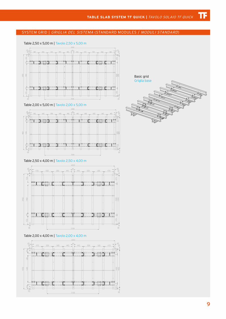
SYSTEM GRID | GRIGLIA DEL SISTEMA (STANDARD MODULES / MODULI STANDARD)
Table 2,50 x 5,00 m | Tavolo 2,50 x 5,00 m
Table 2,00 x 5,00 m | Tavolo 2,00 x 5,00 m
Table 2,50 x 4,00 m | Tavolo 2,50 x 4,00 m
Table 2,00 x 4,00 m | Tavolo 2,00 x 4,00 m
1
1
2
2
3
3
4
4
5
5
6
6
7
7
8
8
A A
B B
C C
D D
E E
F F
G G
H H
SHEET 1 OF 1
DRAWN
CHECKED
QA
MFG
APPROVED
Gianluca 09/12/2015
DWG NO
Trasporto e Stoccaggio Tavoli-1
TITLE
SIZE
30 x 42 (pollici)SCALE
REV
Basic gridGriglia base
10
FAST, EASY and SAFE SYSTEM ERECTION | ARMO RAPIDO, SEMPLICE E SICURO DEL SISTEMA
INTEGRATED CLOSURE SOLUTIONS | SOLUZIONI DI COMPENSAZIONE INTEGRATE
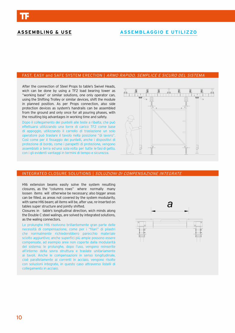
After the connection of Steel Props to table’s Swivel Heads, wich can be done by using a TF2 load bearing tower as “working base” or similar solutions, one only operator can, using the Shifting Trolley or similar devices, shift the module in planned position. As per Props connection, also side protection devices as system’s handrails can be assembled from the ground and only once for all pouring phases, with the resulting big advantages in working time and safety.
Dopo il collegamento dei puntelli alle teste a ribalta, che può effettuarsi utilizzando una torre di carico TF2 come base di appoggio, utilizzando il carrello di traslazione un solo operatore può traslare il tavolo nella posizione “di lavoro”. Così come per il fissaggio dei puntelli, anche i dispositivi di protezione di bordo, come i parapetti di protezione, vengono assemblati a terra ed una sola volta per tutte le fasi di getto, con i gli evidenti vantaggi in termini di tempo e sicurezza.
H16 extension beams easily solve the system resulting closures, as the “columns rows” where normally many loosen items will otherwise be necessary; also bigger areas can be filled, as areas not covered by the system modularity, with same H16 beam; all items will be, after use, re-inserted on tables super structure and jointly shifted.Closures in table’s longitudinal direction, wich minds along the Double C steel walings, are solved by integrated solutions, as the waling connectors.
Le prolunghe H16 risolvono brillantemente gran parte delle necessità di compensazione, come per i “filari” di pilastri che normalmente richiederebbero parecchio materiale sciolto aggiuntivo; anche superfici più ampie possono essere compensate, ad esempio aree non coperte dalla modularità del sistema; le prolunghe, dopo l’uso, vengono reinserite all’interno della sovra struttura e traslate unitariamente ai tavoli. Anche le compensazioni in senso longitudinale, cioè parallelamente ai correnti in acciaio, vengono risolte con soluzioni integrate, in questo caso attraverso listelli di collegamento in acciaio.
ASSEMBLING & USE ASSEMBLAGGIO E UTILIZZO
11
TABLE SLAB SYSTEM TF QUICK | TAVOLO SOLAIO TF QUICK
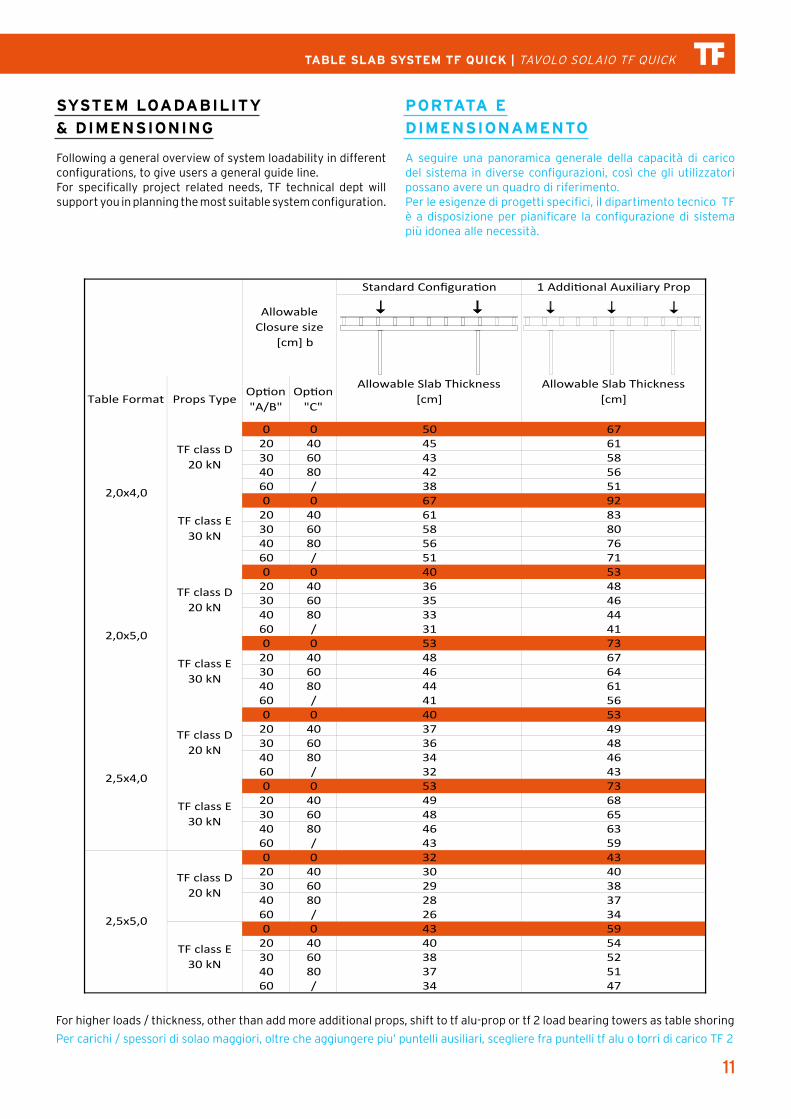
For higher loads / thickness, other than add more additional props, shift to tf alu-prop or tf 2 load bearing towers as table shoring
Per carichi / spessori di solao maggiori, oltre che aggiungere piu’ puntelli ausiliari, scegliere fra puntelli tf alu o torri di carico TF 2
Standard Configuration 1 Additional Auxiliary Prop
Table Format Props TypeOption "A/B"
Option "C"
Allowable Slab Thickness [cm]
Allowable Slab Thickness [cm]
0 0 50 6720 40 45 6130 60 43 5840 80 42 5660 / 38 510 0 67 92
20 40 61 8330 60 58 8040 80 56 7660 / 51 710 0 40 53
20 40 36 4830 60 35 4640 80 33 4460 / 31 410 0 53 73
20 40 48 6730 60 46 6440 80 44 6160 / 41 560 0 40 53
20 40 37 4930 60 36 4840 80 34 4660 / 32 430 0 53 73
20 40 49 6830 60 48 6540 80 46 6360 / 43 590 0 32 43
20 40 30 4030 60 29 3840 80 28 3760 / 26 340 0 43 59
20 40 40 5430 60 38 5240 80 37 5160 / 34 47
2,0x5,0
TF class D 20 kN
TF class E 30 kN
Allowable Closure size
[cm] b
2,0x4,0
TF class D 20 kN
TF class E 30 kN
2,5x4,0
TF class D 20 kN
TF class E 30 kN
2,5x5,0
TF class D 20 kN
TF class E 30 kN
SYSTEM LOADABILITY
& DIMENSIONING
Following a general overview of system loadability in different configurations, to give users a general guide line.For specifically project related needs, TF technical dept will support you in planning the most suitable system configuration.
PORTATA E
DIMENSIONAMENTO
A seguire una panoramica generale della capacità di carico del sistema in diverse configurazioni, così che gli utilizzatori possano avere un quadro di riferimento.Per le esigenze di progetti specifici, il dipartimento tecnico TF è a disposizione per pianificare la configurazione di sistema più idonea alle necessità.
12
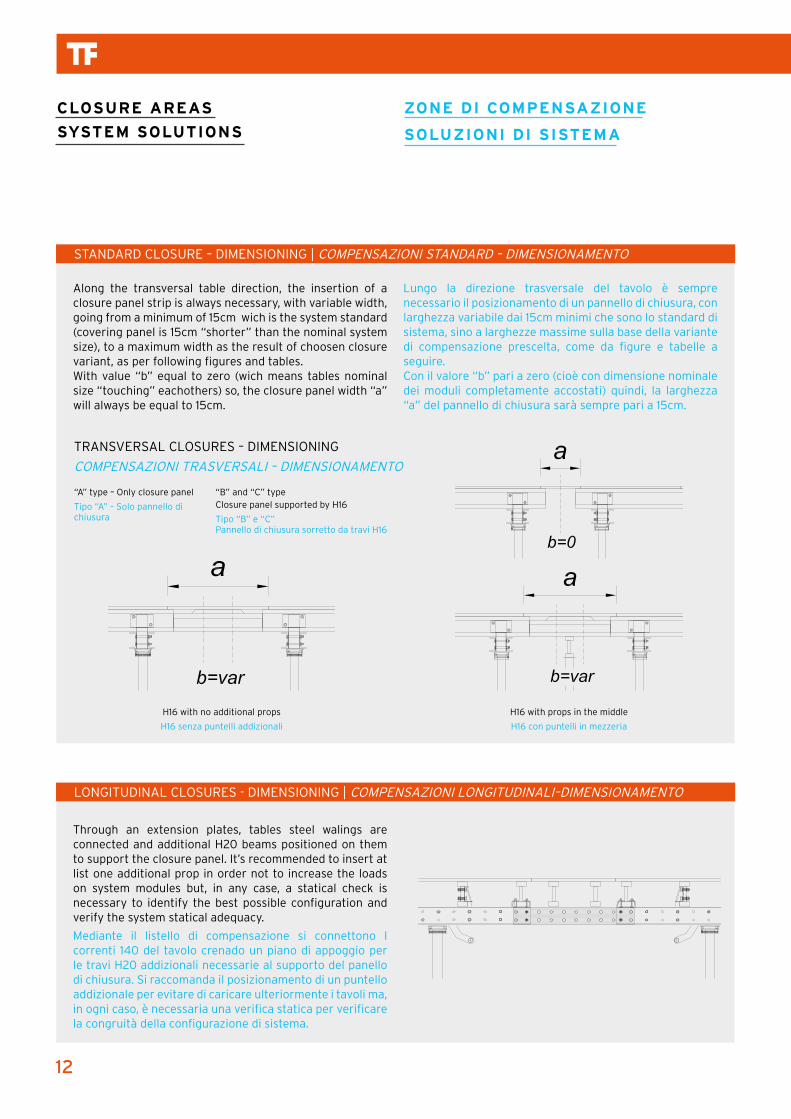
Along the transversal table direction, the insertion of a closure panel strip is always necessary, with variable width, going from a minimum of 15cm wich is the system standard (covering panel is 15cm “shorter” than the nominal system size), to a maximum width as the result of choosen closure variant, as per following figures and tables.With value “b” equal to zero (wich means tables nominal size “touching” eachothers) so, the closure panel width “a” will always be equal to 15cm.
Through an extension plates, tables steel walings are connected and additional H20 beams positioned on them to support the closure panel. It’s recommended to insert at list one additional prop in order not to increase the loads on system modules but, in any case, a statical check is necessary to identify the best possible configuration and verify the system statical adequacy.
Mediante il listello di compensazione si connettono I correnti 140 del tavolo crenado un piano di appoggio per le travi H20 addizionali necessarie al supporto del panello di chiusura. Si raccomanda il posizionamento di un puntello addizionale per evitare di caricare ulteriormente i tavoli ma, in ogni caso, è necessaria una verifica statica per verificare la congruità della configurazione di sistema.
Lungo la direzione trasversale del tavolo è sempre necessario il posizionamento di un pannello di chiusura, con larghezza variabile dai 15cm minimi che sono lo standard di sistema, sino a larghezze massime sulla base della variante di compensazione prescelta, come da figure e tabelle a seguire.Con il valore “b” pari a zero (cioè con dimensione nominale dei moduli completamente accostati) quindi, la larghezza “a” del pannello di chiusura sarà sempre pari a 15cm.
STANDARD CLOSURE – DIMENSIONING | COMPENSAZIONI STANDARD – DIMENSIONAMENTO
LONGITUDINAL CLOSURES - DIMENSIONING | COMPENSAZIONI LONGITUDINALI–DIMENSIONAMENTO
TRANSVERSAL CLOSURES – DIMENSIONING
COMPENSAZIONI TRASVERSALI – DIMENSIONAMENTO
H16 with no additional props
H16 senza puntelli addizionali
H16 with props in the middle
H16 con puntelli in mezzeria
CLOSURE AREAS
SYSTEM SOLUTIONS
ZONE DI COMPENSAZIONE
SOLUZIONI DI SISTEMA
“A” type – Only closure panel
Tipo “A” – Solo pannello di chiusura
“B” and “C” typeClosure panel supported by H16
Tipo “B” e “C”Pannello di chiusura sorretto da travi H16
13
TABLE SLAB SYSTEM TF QUICK | TAVOLO SOLAIO TF QUICK
EDGE MODULES | MODULI PERIMETRALI
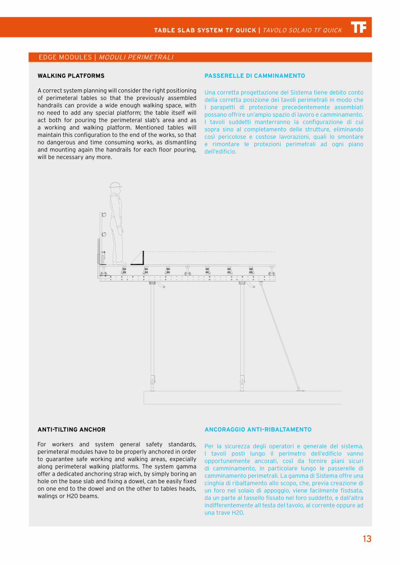
WALKING PLATFORMS
A correct system planning will consider the right positioning of perimeteral tables so that the previously assembled handrails can provide a wide enough walking space, with no need to add any special platform; the table itself will act both for pouring the perimeteral slab’s area and as a working and walking platform. Mentioned tables will maintain this configuration to the end of the works, so that no dangerous and time consuming works, as dismantling and mounting again the handrails for each floor pouring, will be necessary any more.
ANTI-TILTING ANCHOR
For workers and system general safety standards, perimeteral modules have to be properly anchored in order to guarantee safe working and walking areas, expecially along perimeteral walking platforms. The system gamma offer a dedicated anchoring strap wich, by simply boring an hole on the base slab and fixing a dowel, can be easily fixed on one end to the dowel and on the other to tables heads, walings or H20 beams.
PASSERELLE DI CAMMINAMENTO
Una corretta progettazione del Sistema tiene debito conto della corretta posizione dei tavoli perimetrali in modo che I parapetti di protezione precedentemente assemblati possano offrire un’ampio spazio di lavoro e camminamento. I tavoli suddetti manterranno la configurazione di cui sopra sino al completamento delle strutture, eliminando così pericolose e costose lavorazioni, quali lo smontare e rimontare le protezioni perimetrali ad ogni piano dell’edificio.
ANCORAGGIO ANTI-RIBALTAMENTO
Per la sicurezza degli operatori e generale del sistema, I tavoli posti lungo il perimetro dell’edificio vanno opportunemente ancorati, così da fornire piani sicuri di camminamento, in particolare lungo le passerelle di camminamento perimetrali. La gamma di Sistema offre una cinghia di ribaltamento allo scopo, che, previa creazione di un foro nel solaio di appoggio, viene facilmente fisdsata, da un parte al tassello fissato nel foro suddetto, e dall’altra indifferentemente all testa del tavolo, al corrente oppure ad una trave H20.
14
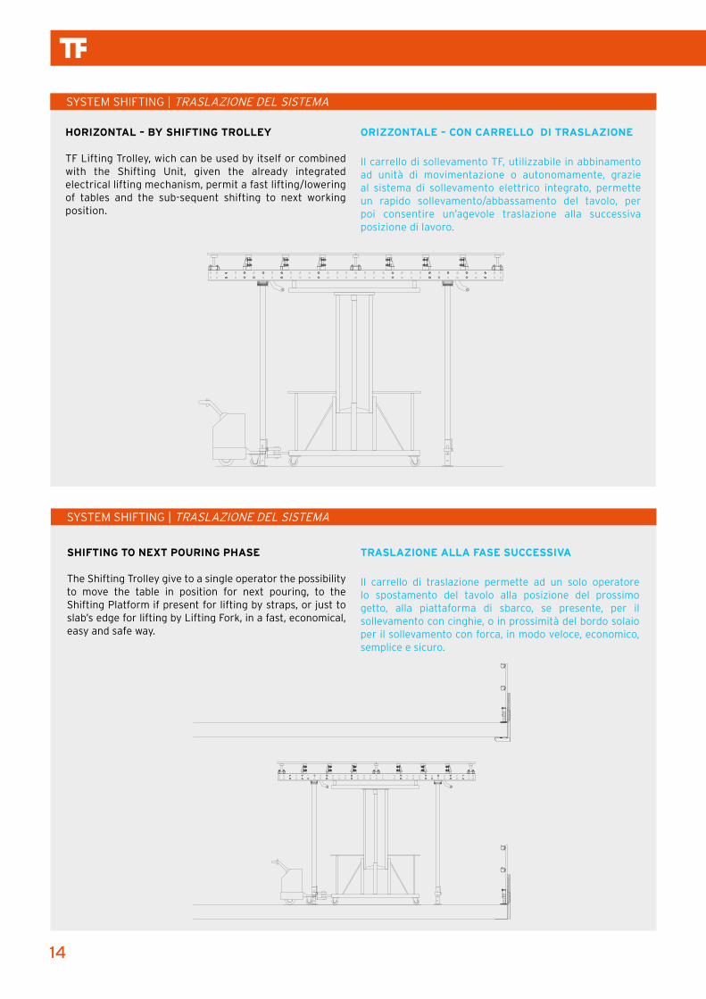
HORIZONTAL – BY SHIFTING TROLLEY
TF Lifting Trolley, wich can be used by itself or combined with the Shifting Unit, given the already integrated electrical lifting mechanism, permit a fast lifting/lowering of tables and the sub-sequent shifting to next working position.
ORIZZONTALE – CON CARRELLO DI TRASLAZIONE
Il carrello di sollevamento TF, utilizzabile in abbinamento ad unità di movimentazione o autonomamente, grazie al sistema di sollevamento elettrico integrato, permette un rapido sollevamento/abbassamento del tavolo, per poi consentire un’agevole traslazione alla successiva posizione di lavoro.
SYSTEM SHIFTING | TRASLAZIONE DEL SISTEMA
SHIFTING TO NEXT POURING PHASE
The Shifting Trolley give to a single operator the possibility to move the table in position for next pouring, to the Shifting Platform if present for lifting by straps, or just to slab’s edge for lifting by Lifting Fork, in a fast, economical, easy and safe way.
TRASLAZIONE ALLA FASE SUCCESSIVA
Il carrello di traslazione permette ad un solo operatore lo spostamento del tavolo alla posizione del prossimo getto, alla piattaforma di sbarco, se presente, per il sollevamento con cinghie, o in prossimità del bordo solaio per il sollevamento con forca, in modo veloce, economico, semplice e sicuro.
SYSTEM SHIFTING | TRASLAZIONE DEL SISTEMA
15
TABLE SLAB SYSTEM TF QUICK | TAVOLO SOLAIO TF QUICK
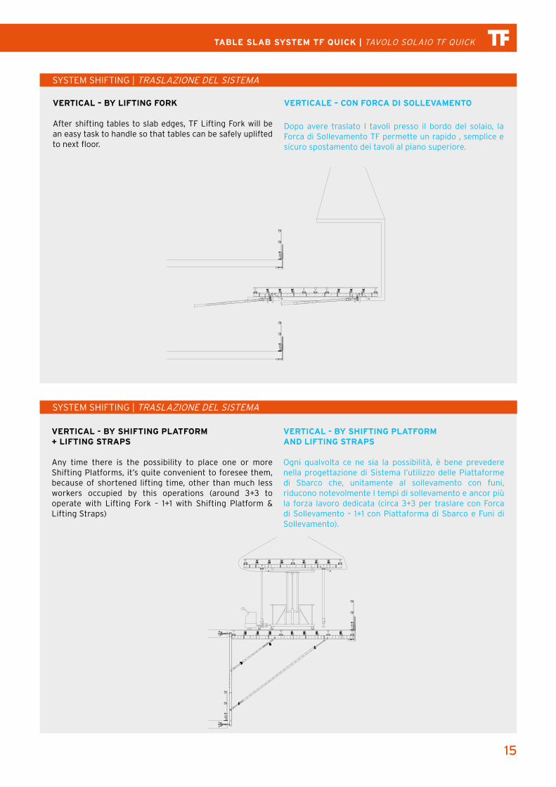
VERTICAL - BY SHIFTING PLATFORM+ LIFTING STRAPS
Any time there is the possibility to place one or more Shifting Platforms, it’s quite convenient to foresee them, because of shortened lifting time, other than much less workers occupied by this operations (around 3+3 to operate with Lifting Fork – 1+1 with Shifting Platform & Lifting Straps)
VERTICAL - BY SHIFTING PLATFORMAND LIFTING STRAPS
Ogni qualvolta ce ne sia la possibilità, è bene prevedere nella progettazione di Sistema l’utilizzo delle Piattaforme di Sbarco che, unitamente al sollevamento con funi, riducono notevolmente I tempi di sollevamento e ancor più la forza lavoro dedicata (circa 3+3 per traslare con Forca di Sollevamento – 1+1 con Piattaforma di Sbarco e Funi di Sollevamento).
SYSTEM SHIFTING | TRASLAZIONE DEL SISTEMA
VERTICAL – BY LIFTING FORK
After shifting tables to slab edges, TF Lifting Fork will be an easy task to handle so that tables can be safely uplifted to next floor.
VERTICALE – CON FORCA DI SOLLEVAMENTO
Dopo avere traslato I tavoli presso il bordo del solaio, la Forca di Sollevamento TF permette un rapido , semplice e sicuro spostamento dei tavoli al piano superiore.
SYSTEM SHIFTING | TRASLAZIONE DEL SISTEMA
16
SYSTEM SHIFTING | TRASLAZIONE DEL SISTEMA
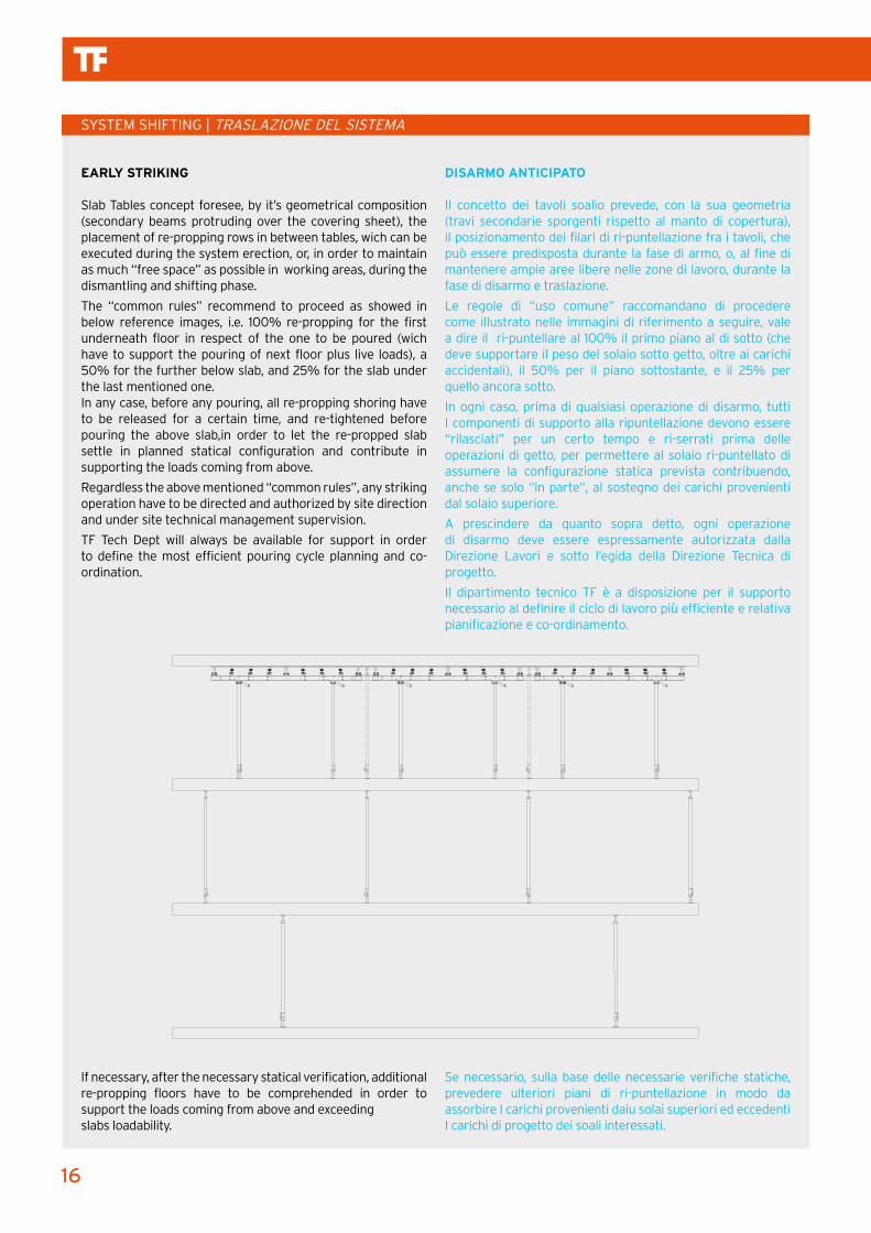
EARLY STRIKING
Slab Tables concept foresee, by it’s geometrical composition (secondary beams protruding over the covering sheet), the placement of re-propping rows in between tables, wich can be executed during the system erection, or, in order to maintain as much “free space” as possible in working areas, during the dismantling and shifting phase.
The “common rules” recommend to proceed as showed in below reference images, i.e. 100% re-propping for the first underneath floor in respect of the one to be poured (wich have to support the pouring of next floor plus live loads), a 50% for the further below slab, and 25% for the slab under the last mentioned one.In any case, before any pouring, all re-propping shoring have to be released for a certain time, and re-tightened before pouring the above slab,in order to let the re-propped slab settle in planned statical configuration and contribute in supporting the loads coming from above.
Regardless the above mentioned “common rules”, any striking operation have to be directed and authorized by site direction and under site technical management supervision.
TF Tech Dept will always be available for support in order to define the most efficient pouring cycle planning and co-ordination.
If necessary, after the necessary statical verification, additional re-propping floors have to be comprehended in order to support the loads coming from above and exceeding slabs loadability.
Se necessario, sulla base delle necessarie verifiche statiche, prevedere ulteriori piani di ri-puntellazione in modo da assorbire I carichi provenienti daiu solai superiori ed eccedenti I carichi di progetto dei soali interessati.
DISARMO ANTICIPATO
Il concetto dei tavoli soalio prevede, con la sua geometria (travi secondarie sporgenti rispetto al manto di copertura), il posizionamento dei filari di ri-puntellazione fra i tavoli, che può essere predisposta durante la fase di armo, o, al fine di mantenere ampie aree libere nelle zone di lavoro, durante la fase di disarmo e traslazione.
Le regole di “uso comune” raccomandano di procedere come illustrato nelle immagini di riferimento a seguire, vale a dire il ri-puntellare al 100% il primo piano al di sotto (che deve supportare il peso del solaio sotto getto, oltre ai carichi accidentali), il 50% per il piano sottostante, e il 25% per quello ancora sotto.
In ogni caso, prima di qualsiasi operazione di disarmo, tutti I componenti di supporto alla ripuntellazione devono essere “rilasciati” per un certo tempo e ri-serrati prima delle operazioni di getto, per permettere al solaio ri-puntellato di assumere la configurazione statica prevista contribuendo, anche se solo “in parte”, al sostegno dei carichi provenienti dal solaio superiore.
A prescindere da quanto sopra detto, ogni operazione di disarmo deve essere espressamente autorizzata dalla Direzione Lavori e sotto l’egida della Direzione Tecnica di progetto.
Il dipartimento tecnico TF è a disposizione per il supporto necessario al definire il ciclo di lavoro più efficiente e relativa pianificazione e co-ordinamento.

17
TABLE SLAB SYSTEM TF QUICK | TAVOLO SOLAIO TF QUICK
TRANSPORT AND STORAGE | TRASPORTO E STOCCAGGIO
LIFTING | SOLLEVAMENTO DEI TAVOLI
Table’s “packages”, up to max 6 tables staked on each other, can be easily uplifted on a truck, reducing logistics and transport time.
I tavoli impilati, sino ad un max di 6 tavoli per imballo, sono agevolmente movimentabili con muletto anche nel carico / scarico, riducendo I tempi logistici e di trasporto.
The single modules or the entire stack (max 6 modules) can be lifted with the aid of Lifting straps. Using 2 straps for each unit shifted. Max loadability 20 kN (2000 kg).
Il singolo tavolo o l’intero imballo (max 6 tavoli) possono essere sollevati mediante le apposite funi di sollevamento. Si utilizzano 2 funi per ogni unità sollevata. Massima capacità di carico 20 kN (2.000 Kg)
1
1
2
2
3
3
4
4
A A
B B
C C
D D
SHEET 1 OF 1
DRAWN
CHECKED
QA
MFG
APPROVED
Gianluca 14/12/2015
DWG NO
STOCCAGGIO
TITLE
SIZE
CSCALE
REV
18
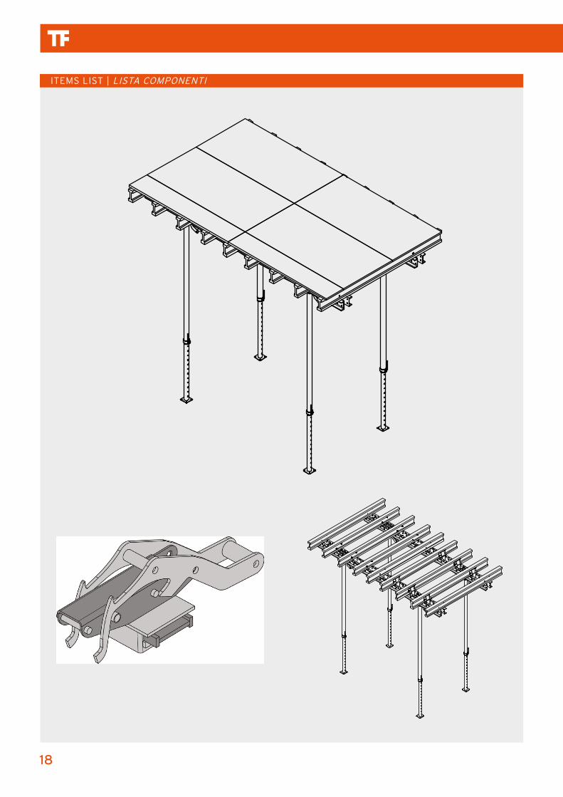
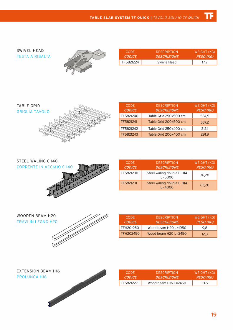
ITEMS LIST | LISTA COMPONENTI
19
TABLE SLAB SYSTEM TF QUICK | TAVOLO SOLAIO TF QUICK
CODECODICE
DESCRIPTIONDESCRIZIONE
WEIGHT (KG)PESO (KG)
TF5821224 Swivle Head 17,2
CODECODICE
DESCRIPTIONDESCRIZIONE
WEIGHT (KG)PESO (KG)
TF5821227 Wood beam H16 L=2450 10,5
CODECODICE
DESCRIPTIONDESCRIZIONE
WEIGHT (KG)PESO (KG)
TF5821240 Table Grid 250x500 cm 524,5
TF5821241 Table Grid 200x500 cm 337,2
TF5821242 Table Grid 250x400 cm 312,1
TF5821243 Table Grid 200x400 cm 291,9
CODECODICE
DESCRIPTIONDESCRIZIONE
WEIGHT (KG)PESO (KG)
TF5821230 Steel waling double C H14 L=5000
76,20
TF5821231 Steel waling double C H14 L=4000
63,20
CODECODICE
DESCRIPTIONDESCRIZIONE
WEIGHT (KG)PESO (KG)
TFH201950 Wood beam H20 L=1950 9,8
TFH202450 Wood beam H20 L=2450 12,3
1
1
2
2
3
3
4
4
A A
B B
C C
D D
SHEET 1 OF 1
DRAWN
CHECKED
QA
MFG
APPROVED
Gianluca 18/12/2015
DWG NO
TITLE
SIZE
CSCALE
REV
1
1
2
2
3
3
4
4
5
5
6
6
7
7
8
8
A A
B B
C C
D D
E E
F F
G G
H H
SHEET 1 OF 1
DRAWN
CHECKED
QA
MFG
APPROVED
Gianluca 09/12/2015
DWG NO
Trasporto e Stoccaggio Tavoli-1
TITLE
SIZE
30 x 42 (pollici)SCALE
REV
1
1
2
2
3
3
4
4
5
5
6
6
7
7
8
8
A A
B B
C C
D D
E E
F F
G G
H H
SHEET 1 OF 1
DRAWN
CHECKED
QA
MFG
APPROVED
Gianluca 09/12/2015
DWG NO
Trasporto e Stoccaggio Tavoli-1
TITLE
SIZE
30 x 42 (pollici)SCALE
REV
1
1
2
2
3
3
4
4
5
5
6
6
7
7
8
8
A A
B B
C C
D D
E E
F F
G G
H H
SHEET 1 OF 1
DRAWN
CHECKED
QA
MFG
APPROVED
Gianluca 09/12/2015
DWG NO
Trasporto e Stoccaggio Tavoli-1
TITLE
SIZE
30 x 42 (pollici)SCALE
REV
SWIVEL HEAD
TESTA A RIBALTA
TABLE GRID
GRIGLIA TAVOLO
STEEL WALING C 140
CORRENTE IN ACCIAIO C 140
WOODEN BEAM H20
TRAVI IN LEGNO H20
EXTENSION BEAM H16
PROLUNGA H16
20
CODECODICE
DESCRIPTIONDESCRIZIONE
WEIGHT (KG)PESO (KG)
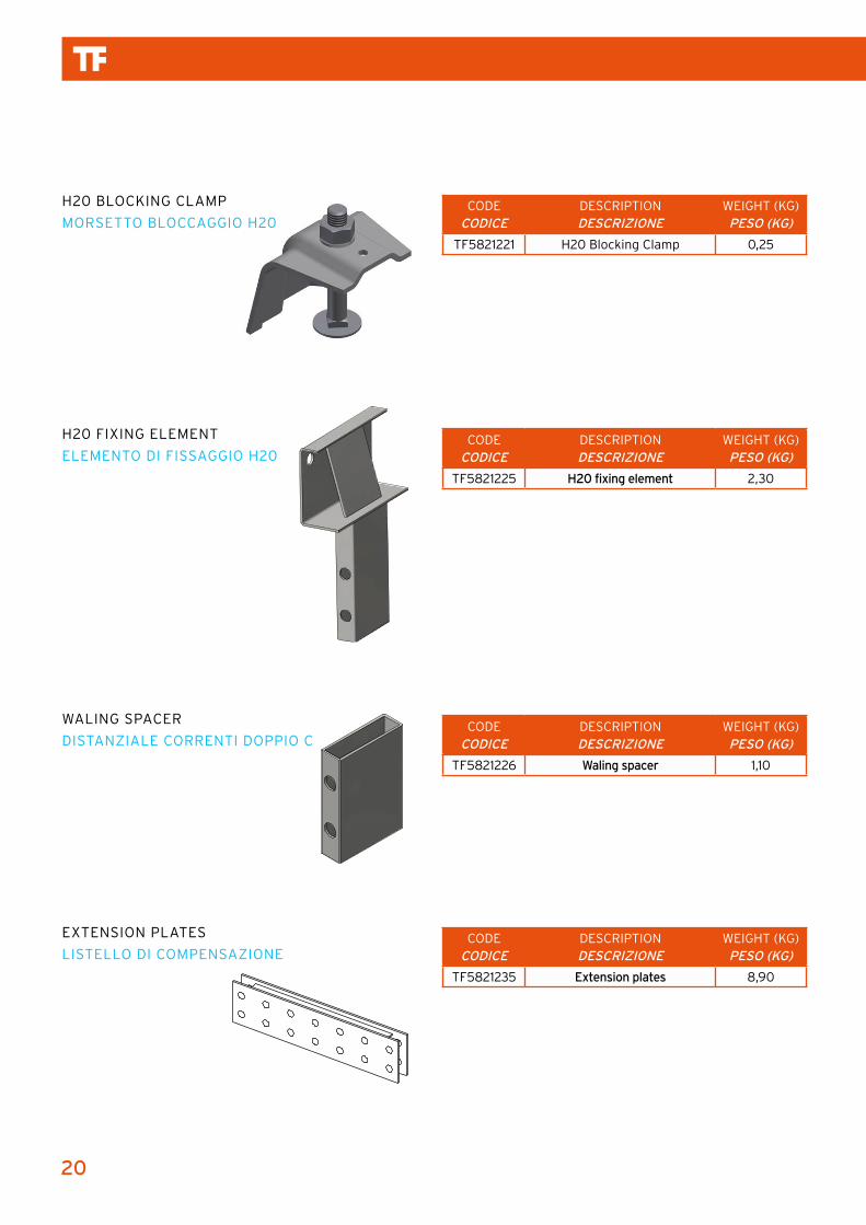
TF5821221 H20 Blocking Clamp 0,25
CODECODICE
DESCRIPTIONDESCRIZIONE
WEIGHT (KG)PESO (KG)
TF5821225 H20 fixing element 2,30
CODECODICE
DESCRIPTIONDESCRIZIONE
WEIGHT (KG)PESO (KG)
TF5821226 Waling spacer 1,10
CODECODICE
DESCRIPTIONDESCRIZIONE
WEIGHT (KG)PESO (KG)
TF5821235 Extension plates 8,90
H20 BLOCKING CLAMP
MORSETTO BLOCCAGGIO H20
H20 FIXING ELEMENT
ELEMENTO DI FISSAGGIO H20
WALING SPACER
DISTANZIALE CORRENTI DOPPIO C
EXTENSION PLATES
LISTELLO DI COMPENSAZIONE

21
TABLE SLAB SYSTEM TF QUICK | TAVOLO SOLAIO TF QUICK
CODECODICE
DESCRIPTIONDESCRIZIONE
WEIGHT (KG)PESO (KG)
TF5821233 Lifting fork 550
CODECODICE
DESCRIPTIONDESCRIZIONE
WEIGHT (KG)PESO (KG)
TF5804700 Clamp Handrail 11,5
PROP EN1065 CLASS D / E
PUNTELLO EN1065 CLASSE D / E
LIFTING FORK
FORCA DI SOLLEVAMENTO
CLAMP HANDRAIL
PARAPETTO A MORSA
CODECODICE
DESCRIPTIONDESCRIZIONE
WEIGHT (KG)PESO (KG)
TFH20D30 Prop D30 Galvanized 17,80
TFH20D35 Prop D35 Galvanized 19,58
TFH20D40 Prop D40 Galvanized 22,46
TFH20D45 Prop D45 Galvanized 27,10
TFH20D50 Prop D50 Galvanized 34,10
TFH20D55 Prop D55 Galvanized 35,11
TFH20E25 Prop E25 Galvanized 15,10
TFH20E30 Prop E30 Galvanized 18,34
TFH20E35 Prop E35 Galvanized 23,46
TFH20E40 Prop E40 Galvanized 26,90
TFH20E45 Prop E45 Galvanized 31,44
TFH20EXTE45 Extension for Prop E45 - 50 cm ...........
CODECODICE
DESCRIPTIONDESCRIZIONE
WEIGHT (KG)PESO (KG)
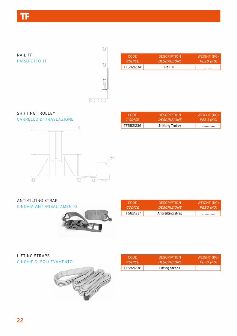
TF5821234 Rail TF ..........
CODECODICE
DESCRIPTIONDESCRIZIONE
WEIGHT (KG)PESO (KG)
TF5821236 Shifting Trolley ...............
CODECODICE
DESCRIPTIONDESCRIZIONE
WEIGHT (KG)PESO (KG)
TF5821237 Anti-tilting strap ...............
CODECODICE
DESCRIPTIONDESCRIZIONE
WEIGHT (KG)PESO (KG)
TF5821238 Lifting straps ...............
RAIL TF
PARAPETTO TF
SHIFTING TROLLEY
CARRELLO DI TRASLAZIONE
ANTI-TILTING STRAP
CINGHIA ANTI-RIBALTAMENTO
LIFTING STRAPS
CINGHIE DI SOLLEVAMENTO
22


THE FORMWORK SRL
Via Achille Grandi, 7 - 20097 San Donato Milanese (Milano) - Italy
Tel. +39 02 5275829 - 02 5279974 - Fax +39 02 55600291
[email protected] | www.theformwork.it


![[PPT]Grillage Analysis for Slab & Pseudo-Slab Bridge Decksenggprog.com/Downloads/Lectures/BridgeEngg/Lecture No. 3... · Web viewTitle Grillage Analysis for Slab & Pseudo-Slab Bridge](https://static.documents.pub/doc/80x56/5adedacf7f8b9afd1a8beaa6/pptgrillage-analysis-for-slab-pseudo-slab-bridge-no-3web-viewtitle-grillage.jpg)