TACKLING THE CHALLENGES OF FULL PIT LATRINES Volume 3: The development of pit emptying technologies Report to the Water Research Commission by David Still 1 & Mark O’Riordan 2 1 Partners in Development 2 Engineers without Borders, UK WRC Report No. 1745/3/12 ISBN 978-1-4312-0293-5 Set No. 978-1-4312-0294-2 July 2012
Transcript
TACKLING THE CHALLENGES OF FULL PIT LATRINES Volume 3: The development of pit emptying technologies
Report to the
Water Research Commission
by
David Still1 & Mark O’Riordan
2
1Partners in Development 2Engineers without Borders, UK
2 TOOL TO AID MANUAL EXHAUSTION ............................................................................ 6
3 THE GOBBLER ...................................................................................................................... 8
3.1 Design development ............................................................................................................................... 8
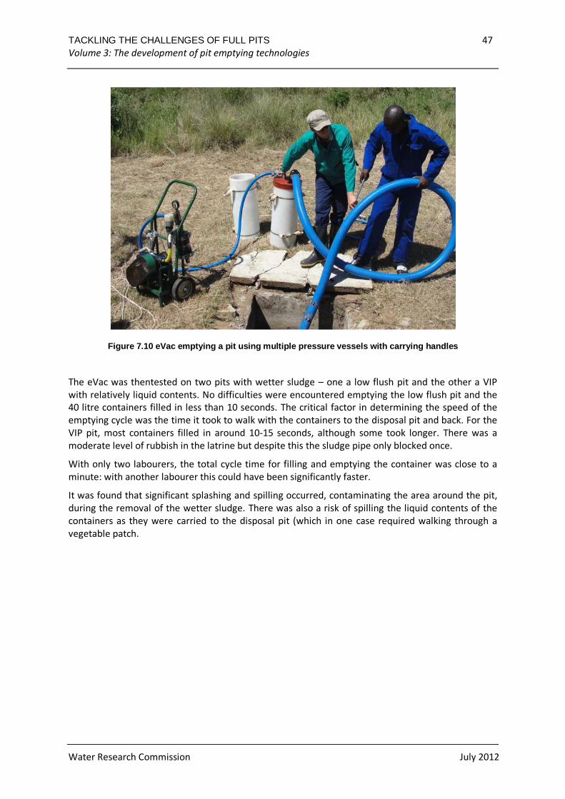
Figure 7.10 eVac emptying a pit using multiple pressure vessels with carrying handles ................................... 47
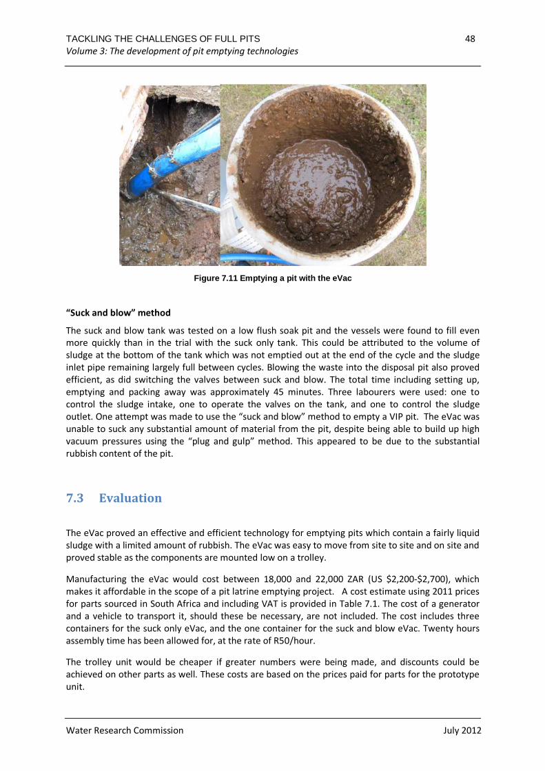
Figure 7.11 Emptying a pit with the eVac ........................................................................................................ 48
TACKLING THE CHALLENGES OF FULL PITS 1 Volume 3: The development of pit emptying technologies
Water Research Commission July 2012
1 INTRODUCTION
An on-site sanitation system requires a pit to collect accumulating sludge. The pit eventually reaches
capacity. When it does, the alternatives are either to empty the pit and continue using it or to dig a
new pit and move the top structure. If the sludge is to be removed, a number of issues must be
considered. How accessible is the site and the pit for equipment and vehicles? What equipment will
be able to effectively remove the sludge and how much will it cost (considering operator costs,
capital and operations costs of equipment and filling/emptying frequency of pits)? How will workers
and householders be protected from exposure to pathogens during pit emptying? How will the
sludge be transported and how will it be used or disposed of?
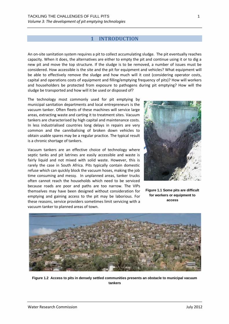
The technology most commonly used for pit emptying by
municipal sanitation departments and local entrepreneurs is the
vacuum tanker. Often fleets of these machines will service large
areas, extracting waste and carting it to treatment sites. Vacuum
tankers are characterised by high capital and maintenance costs.
In less industrialised countries long delays in repairs are very
common and the cannibalising of broken down vehicles to
obtain usable spares may be a regular practice. The typical result
is a chronic shortage of tankers.
Vacuum tankers are an effective choice of technology where
septic tanks and pit latrines are easily accessible and waste is
fairly liquid and not mixed with solid waste. However, this is
rarely the case in South Africa. Pits typically contain domestic
refuse which can quickly block the vacuum hoses, making the job
time consuming and messy. In unplanned areas, tanker trucks
often cannot reach the households which need to be serviced
because roads are poor and paths are too narrow. The VIPs
themselves may have been designed without consideration for
emptying and gaining access to the pit may be laborious. For
these reasons, service providers sometimes limit servicing with a
vacuum tanker to planned areas of town.
Figure 1.2 Access to pits in densely settled commu nities presents an obstacle to municipal vacuum tankers
Figure 1.1 Some pits are difficult for workers or equipment to
access
TACKLING THE CHALLENGES OF FULL PITS 2 Volume 3: The development of pit emptying technologies
Water Research Commission July 2012
A number of alternative technologies have been developed to address the challenges of pit
emptying. Some of these rely only on manual power with the aid of hand tools, some are semi-
mechanised (using manual power transferred through a mechanism) and others are fully
mechanized systems which employ power from an engine or motor.
The most basic approach to removing sludge from a pit is to empty it manually with the use of hand
tools. One of the many disadvantages of emptying pits manually is the length of time required to
empty each pit. Despite the difficulties involved in manual pit emptying, it does have some
advantages. It is a method which is very robust. Since it requires many workers, if one is ill work can
still continue. In contrast, if a machine is used for emptying and it runs out of fuel or breaks, work
grinds to a halt. In addition, manual emptying relies on local labour. This means that funding is spent
in the community rather than tied up in expensive machinery and maintenance costs, also making it
more feasible for small businesses. This brings additional benefits to the community beyond the
emptying of latrines. The benefits however must be balanced against health risks and social
acceptance. If the consistency of the sludge is wet, manual emptying may not be a viable option.
Figure 1.3 below shows the hand tools developed by the eThekwini Metropolitian Municipality
(Durban, South Africa) for its pit emptying programme. The long handled shovel/scoop (centre and
right) was found to be too heavy and was not much used in the field.
Figure 1.3 Tools used for manual pit emptying at eT hekwini
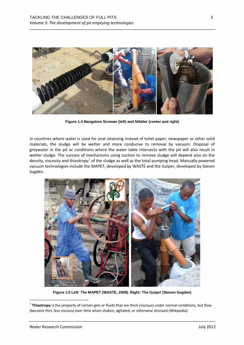
Semi-mechanised technologies which have been tried to remove drier sludge include the Bangalore
Screwer, an Indian-designed device which is based on the principle of using an auger screw to lift
sludge from the pit, and the Nibbler, a device designed by Steve Sugden which uses scoops on a
chain to life waste. Both are operated with a hand crank. Neither have been taken beyond the early
prototype stage. These two devices are shown in Figure 1.4.
TACKLING THE CHALLENGES OF FULL PITS 3 Volume 3: The development of pit emptying technologies
Water Research Commission July 2012
Figure 1.4 Bangalore Screwer (left) and Nibbler (ce nter and right)
In countries where water is used for anal cleansing instead of toilet paper, newspaper or other solid
materials, the sludge will be wetter and more conducive to removal by vacuum. Disposal of
greywater in the pit or conditions where the water table intersects with the pit will also result in
wetter sludge. The success of mechanisms using suction to remove sludge will depend also on the
density, viscosity and thixotropy1 of the sludge as well as the total pumping head. Manually powered
vacuum technologies include the MAPET, developed by WASTE and the Gulper, developed by Steven
Sugden.
Figure 1.5 Left: The MAPET (WASTE, 2009). Right: Th e Gulper (Steven Sugden)
1 Thixotropy is the property of certain gels or fluids that are thick (viscous) under normal conditions, but flow
(become thin, less viscous) over time when shaken, agitated, or otherwise stressed (Wikipedia)
TACKLING THE CHALLENGES OF FULL PITS 4 Volume 3: The development of pit emptying technologies
Water Research Commission July 2012
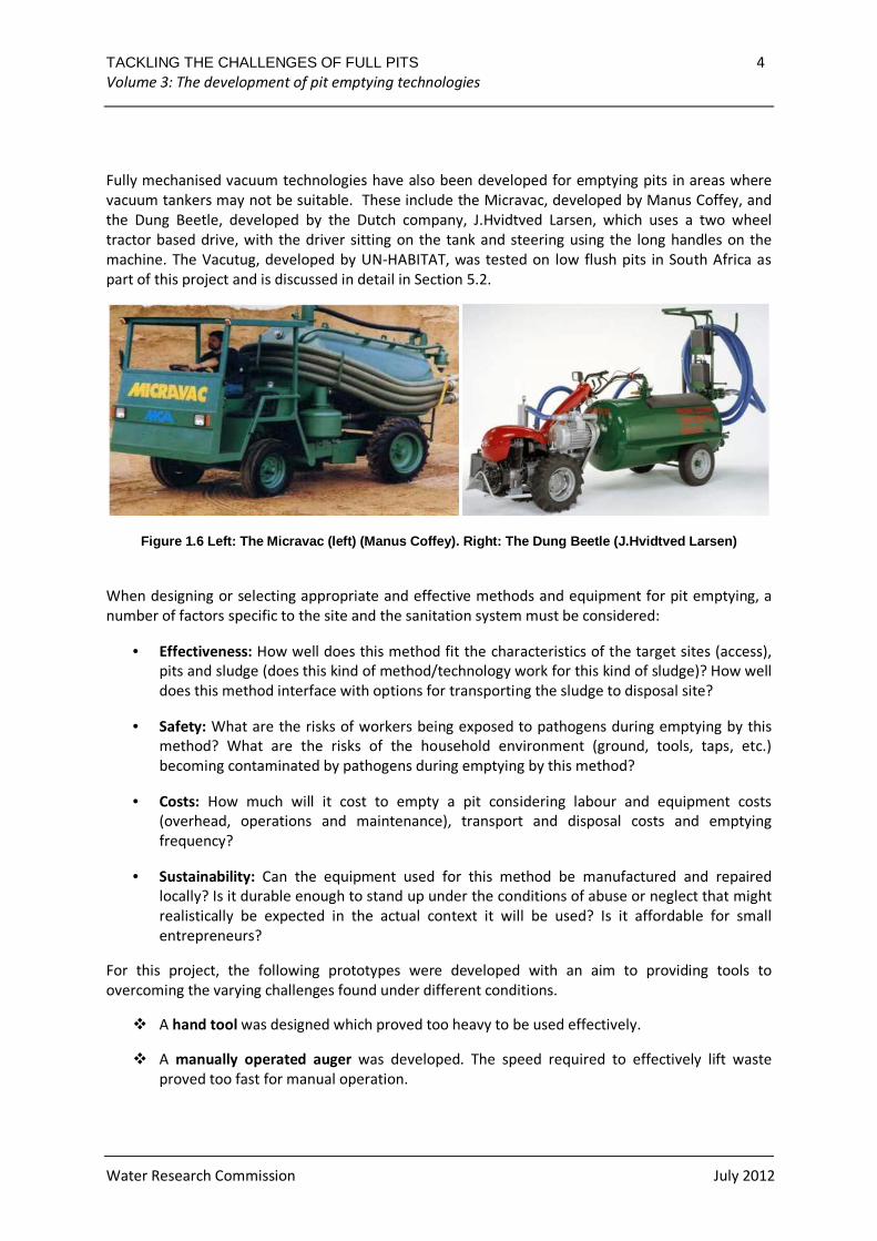
Fully mechanised vacuum technologies have also been developed for emptying pits in areas where
vacuum tankers may not be suitable. These include the Micravac, developed by Manus Coffey, and
the Dung Beetle, developed by the Dutch company, J.Hvidtved Larsen, which uses a two wheel
tractor based drive, with the driver sitting on the tank and steering using the long handles on the
machine. The Vacutug, developed by UN-HABITAT, was tested on low flush pits in South Africa as
part of this project and is discussed in detail in Section 5.2.
Figure 1.6 Left: The Micravac (left) (Manus Coffey) . Right: The Dung Beetle (J.Hvidtved Larsen)
When designing or selecting appropriate and effective methods and equipment for pit emptying, a
number of factors specific to the site and the sanitation system must be considered:
• Effectiveness: How well does this method fit the characteristics of the target sites (access),
pits and sludge (does this kind of method/technology work for this kind of sludge)? How well
does this method interface with options for transporting the sludge to disposal site?
• Safety: What are the risks of workers being exposed to pathogens during emptying by this
method? What are the risks of the household environment (ground, tools, taps, etc.)
becoming contaminated by pathogens during emptying by this method?
• Costs: How much will it cost to empty a pit considering labour and equipment costs
(overhead, operations and maintenance), transport and disposal costs and emptying
frequency?
• Sustainability: Can the equipment used for this method be manufactured and repaired
locally? Is it durable enough to stand up under the conditions of abuse or neglect that might
realistically be expected in the actual context it will be used? Is it affordable for small
entrepreneurs?
For this project, the following prototypes were developed with an aim to providing tools to
overcoming the varying challenges found under different conditions.
� A hand tool was designed which proved too heavy to be used effectively.
� A manually operated auger was developed. The speed required to effectively lift waste
proved too fast for manual operation.
TACKLING THE CHALLENGES OF FULL PITS 5 Volume 3: The development of pit emptying technologies
Water Research Commission July 2012
� Pit Screw Auger. The manual auger was developed into a fully mechanised auger which has
proven effective in lifting drier sludge under controlled conditions.
� Gobbler. The design principles using scoops and a chain used for the Nibbler were
developed further.
� NanoVac. A vacuum technology using piston pumps which has proven effective for pumping
wetter sludge under controlled conditions.
� eVac. A vacuum technology using a vane pump which has proven effective for pumping
wetter sludge under controlled conditions.
� A pressure vessel was developed which can either collect sludge or pump air or water into a
pit to aid sludge removal.
While a number of these technologies have proved effective when trialled on pig slurry, to date
only the eVac appears to have significant potential for usage in field conditions with actual pit
latrines, and then only with wetter sludge which does not have a high solid waste content. This
is however useful as such sludge cannot be easily emptied by hand.
The balance of this report describes the work done and the lessons learned in the process of
researching the above concepts.
TACKLING THE CHALLENGES OF FULL PITS 6 Volume 3: The development of pit emptying technologies
Water Research Commission July 2012
2 TOOL TO AID MANUAL EXHAUSTION
The possibility of modifying existing tools to produce an enclosed spade in order to aid manual
exhaustion was explored. The design concept was that the tool should enable a pit emptier to
remain outside of the pit when extracting waste and to increase the rate at which the waste is
removed. In addition, the tool should be inexpensive, light weight, easy to operate and have few
moving parts.
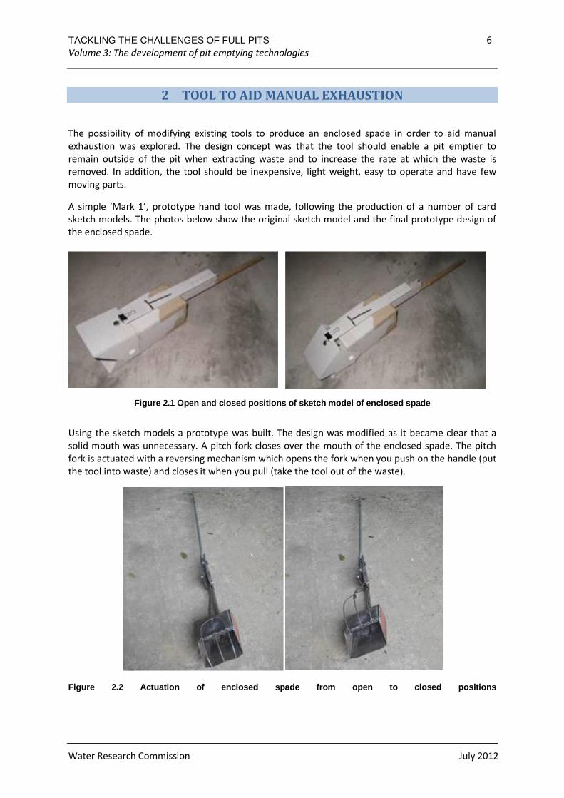
A simple ‘Mark 1’, prototype hand tool was made, following the production of a number of card
sketch models. The photos below show the original sketch model and the final prototype design of
the enclosed spade.
Figure 2.1 Open and closed positions of sketch mode l of enclosed spade
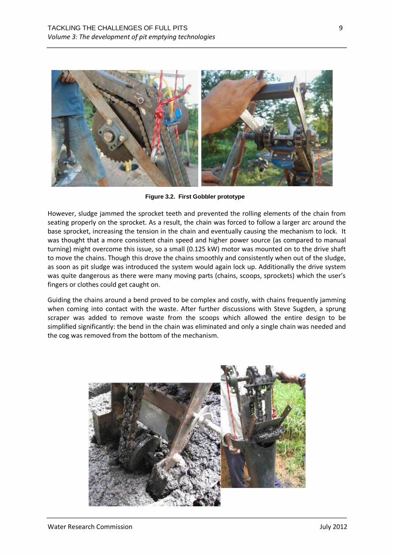
Using the sketch models a prototype was built. The design was modified as it became clear that a
solid mouth was unnecessary. A pitch fork closes over the mouth of the enclosed spade. The pitch
fork is actuated with a reversing mechanism which opens the fork when you push on the handle (put
the tool into waste) and closes it when you pull (take the tool out of the waste).
Figure 2.2 Actuation of enclosed spade from open to closed positions
TACKLING THE CHALLENGES OF FULL PITS 7 Volume 3: The development of pit emptying technologies
Water Research Commission July 2012
The design was marginally effective at lifting waste. The piercing action of the fork mouth (as
opposed to a solid sheet mouth) made the reversing mechanism fairly redundant. The original intent
was to force a solid mouth to close when lifting waste as the weight of the waste might encourage a
solid mouth to open on lifting the tool. With the improved forked mouth this tendency to open is
eliminated as the weight of the waste has little effect on the movement of the forks
Due to the limited success of this design, further development was stopped. The total weight of the
tool was far too high due to the steel construction. For this design to be functional, the following is
recommended:
• Both short and long versions of the tool should be developed: the shorter to be used first
when the sludge level is higher and the longer to be used when the emptier is working at a
deeper level in the pit.
• Pit emptiers should work in pairs, with each having both short and long versions of the tool.
One could then dig sludge from the pit and switch tools with the other who would empty the
sludge into the container or burial pit.
• While holding the waste in the container using forks rather than a solid mouth appears to be
effective, the design needs to be further modified to significantly reduce the weight of the
tool.
TACKLING THE CHALLENGES OF FULL PITS 8 Volume 3: The development of pit emptying technologies
Water Research Commission July 2012
3 THE GOBBLER
While the development of the Nibbler in Tanzania was limited by the availability of parts and
technology, South Africa’s well developed market for agricultural machinery offered a wider range
options. The Gobbler – a more robust version of the Nibbler – was developed as part of this
research.
3.1 Design development
The initial prototype, which cost approximately R10 000 to develop, included a bend in the path of
the chain to allow gravity to assist in pulling the pit sludge off the chain. As it would be difficult to
guide a single chain and scoops around a bend without the scoops fouling on any guiding mechanism
on the inside of the bend, the design utilised two chains rather than the one seen in the Nibbler. The
use of two chains gave the design advantage of being able to place the scoops between them,
leaving both sides of the chains clear for guiding. Guiding the chains, however, proved to be a major
design challenge. Initially, a steel channel was used to guide the chain along its curved path.
However, sludge quickly jammed the spaces between the chain and the steel channel chain guide.
Additionally, the gaps between the rollers in the chain jammed, causing the chain to ride off the
sprockets, resulting in further jamming.
Figure 3.1 Initial design concept for the Gobbler
The steel channel was then replaced with sprockets keyed onto shafts to keep them in phase on the
top and bottom shafts. Sprockets were also used to guide the chain around the inside of the bend.
To overcome the issues of the scoops clashing with the sprocket axles, large 38 toothed sprockets
were used which moved the shaft out of the path of the scoops. A lighter, stronger frame was built.
TACKLING THE CHALLENGES OF FULL PITS 9 Volume 3: The development of pit emptying technologies
Water Research Commission July 2012
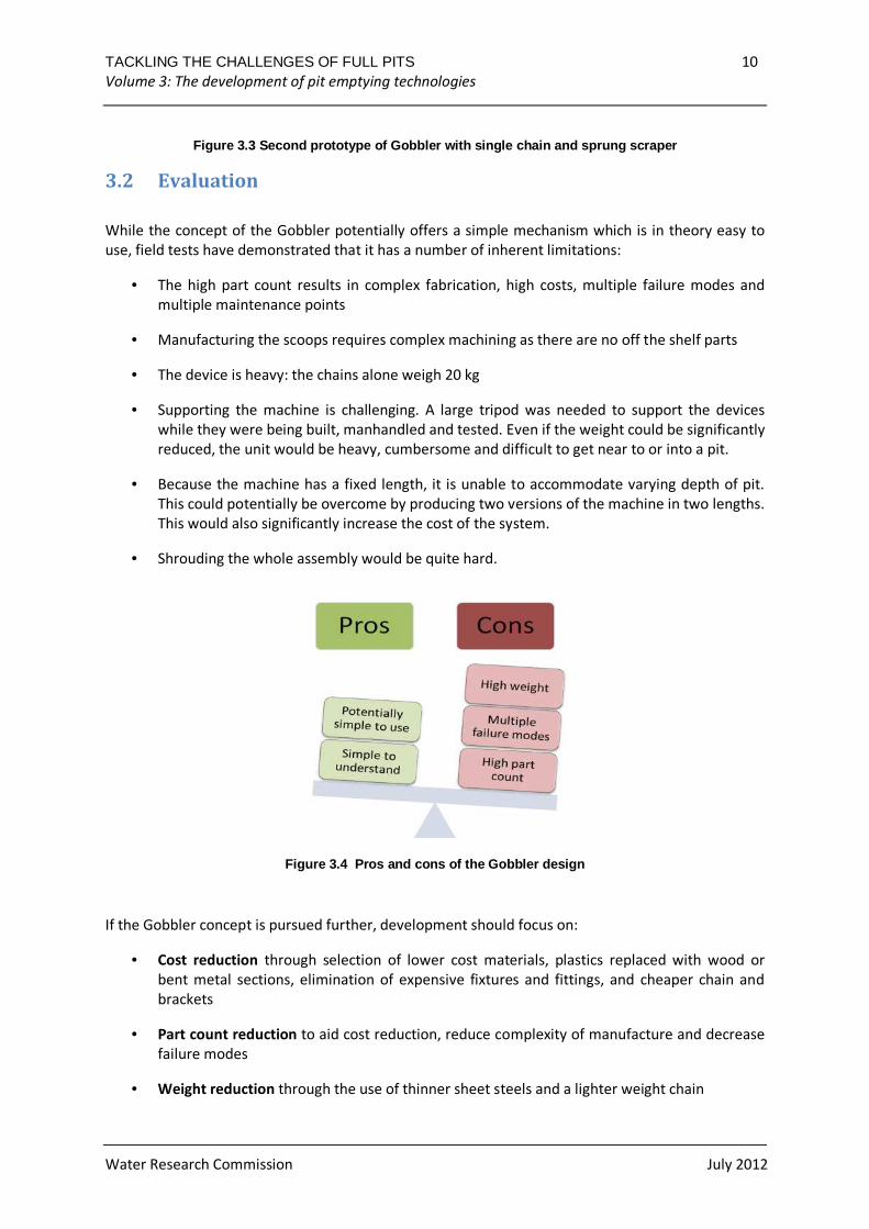
However, sludge jammed the sprocket teeth and prevented the rolling elements of the chain from
seating properly on the sprocket. As a result, the chain was forced to follow a larger arc around the
base sprocket, increasing the tension in the chain and eventually causing the mechanism to lock. It
was thought that a more consistent chain speed and higher power source (as compared to manual
turning) might overcome this issue, so a small (0.125 kW) motor was mounted on to the drive shaft
to move the chains. Though this drove the chains smoothly and consistently when out of the sludge,
as soon as pit sludge was introduced the system would again lock up. Additionally the drive system
was quite dangerous as there were many moving parts (chains, scoops, sprockets) which the user’s
fingers or clothes could get caught on.
Guiding the chains around a bend proved to be complex and costly, with chains frequently jamming
when coming into contact with the waste. After further discussions with Steve Sugden, a sprung
scraper was added to remove waste from the scoops which allowed the entire design to be
simplified significantly: the bend in the chain was eliminated and only a single chain was needed and
the cog was removed from the bottom of the mechanism.
Figure 3.2. First Gobbler prototype
TACKLING THE CHALLENGES OF FULL PITS 10 Volume 3: The development of pit emptying technologies
Water Research Commission July 2012
Figure 3.3 Second prototype of Gobbler with single chain and sprung scraper
3.2 Evaluation
While the concept of the Gobbler potentially offers a simple mechanism which is in theory easy to
use, field tests have demonstrated that it has a number of inherent limitations:
• The high part count results in complex fabrication, high costs, multiple failure modes and
multiple maintenance points
• Manufacturing the scoops requires complex machining as there are no off the shelf parts
• The device is heavy: the chains alone weigh 20 kg
• Supporting the machine is challenging. A large tripod was needed to support the devices
while they were being built, manhandled and tested. Even if the weight could be significantly
reduced, the unit would be heavy, cumbersome and difficult to get near to or into a pit.
• Because the machine has a fixed length, it is unable to accommodate varying depth of pit.
This could potentially be overcome by producing two versions of the machine in two lengths.
This would also significantly increase the cost of the system.
• Shrouding the whole assembly would be quite hard.
Figure 3.4 Pros and cons of the Gobbler design
If the Gobbler concept is pursued further, development should focus on:
• Cost reduction through selection of lower cost materials, plastics replaced with wood or
bent metal sections, elimination of expensive fixtures and fittings, and cheaper chain and
brackets
• Part count reduction to aid cost reduction, reduce complexity of manufacture and decrease
failure modes
• Weight reduction through the use of thinner sheet steels and a lighter weight chain
TACKLING THE CHALLENGES OF FULL PITS 11 Volume 3: The development of pit emptying technologies
Water Research Commission July 2012
4 PIT SCREW AUGER
Augers use a screw to lift material through a pipe. Initially a manually powered auger was tested, but
the necessary rotational speed proved impractical; this led to the development of a fully mechanised
auger. The intention was to produce a device that could be operated by a single person and remove
dry waste from a pit through a pedestal and into a container.
4.1 Development of manually powered prototype
The project team attempted to bend discs cut from sheet steel into a helical shape and then weld
these onto a central shaft. Pulling the helix proved very difficult; thinner sheet metal made bending
easier but resulted in limited material upon which to weld. Eventually a relatively expensive post
hole drilling auger was sourced. A modular injection moulded auger section or a part sourced from
manufacturer which makes livestock feed moving machines are potential alternatives.
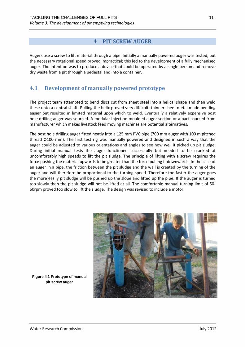
The post hole drilling auger fitted neatly into a 125 mm PVC pipe (700 mm auger with 100 m pitched
thread Ø100 mm). The first test rig was manually powered and designed in such a way that the
auger could be adjusted to various orientations and angles to see how well it picked up pit sludge.
During initial manual tests the auger functioned successfully but needed to be cranked at
uncomfortably high speeds to lift the pit sludge. The principle of lifting with a screw requires the
force pushing the material upwards to be greater than the force pulling it downwards. In the case of
an auger in a pipe, the friction between the pit sludge and the wall is created by the turning of the
auger and will therefore be proportional to the turning speed. Therefore the faster the auger goes
the more easily pit sludge will be pushed up the slope and lifted up the pipe. If the auger is turned
too slowly then the pit sludge will not be lifted at all. The comfortable manual turning limit of 50-
60rpm proved too slow to lift the sludge. The design was revised to include a motor.
Figure 4.1 Prototype of manual pit screw auger
TACKLING THE CHALLENGES OF FULL PITS 12 Volume 3: The development of pit emptying technologies
Water Research Commission July 2012
4.2 Development of mechanised prototype
The objective in the development of the powered auger was that it should be simpler to make than
the Gobbler prototype, be lighter and have a lower part count. As the test rig used for the manual
PSA prototype had proven successful, an electric motor was mounted onto the same rig.
4.2.1 Power
A 0.25 kW motor (1400 RPM) with a 15:1 reduction gearbox was used, giving an output RPM of
approximately 90. When an extension piece was added to the auger, however, the motor began to
cut out frequently and a 20:1 box was tested to increase the torque on the auger with reduced
loading on the motor. The rotational speed of the auger was too low, however, to significantly
improve the lifting and extraction of waste. Testing demonstrated that there is a critical RPM below
which no waste will be lifted. Above this RPM, the faster the auger turns the greater the flow rate of
the lifted waste. With the 100 mm diameter/100 mm pitch auger, the critical RPM was found to be
approximately 60. A 1.1 kW motor was added which provides greater power but also adds weight.
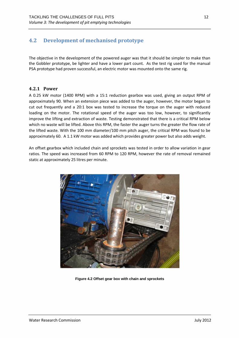
An offset gearbox which included chain and sprockets was tested in order to allow variation in gear
ratios. The speed was increased from 60 RPM to 120 RPM, however the rate of removal remained
static at approximately 25 litres per minute.
Figure 4.2 Offset gear box with chain and sprockets
TACKLING THE CHALLENGES OF FULL PITS 13 Volume 3: The development of pit emptying technologies
Water Research Commission July 2012
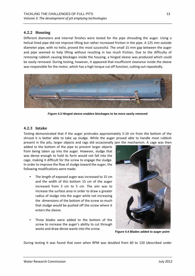
4.2.2 Housing
Different diameters and internal finishes were tested for the pipe shrouding the auger. Using a
helical lined pipe did not improve lifting but rather increased friction in the pipe. A 125 mm outside
diameter pipe, with no helix, proved the most successful. The small 15 mm gap between the auger
and pipe seemed to help lifting without resulting in too much friction. Due to the difficulty of
removing rubbish causing blockages inside the housing, a hinged sleeve was produced which could
be easily removed. During testing, however, it appeared that insufficient clearance inside the sleeve
was responsible for the motor, which has a high torque cut off function, cutting out repeatedly.
Figure 4.3 Hinged sleeve enables blockages to be mo re easily removed
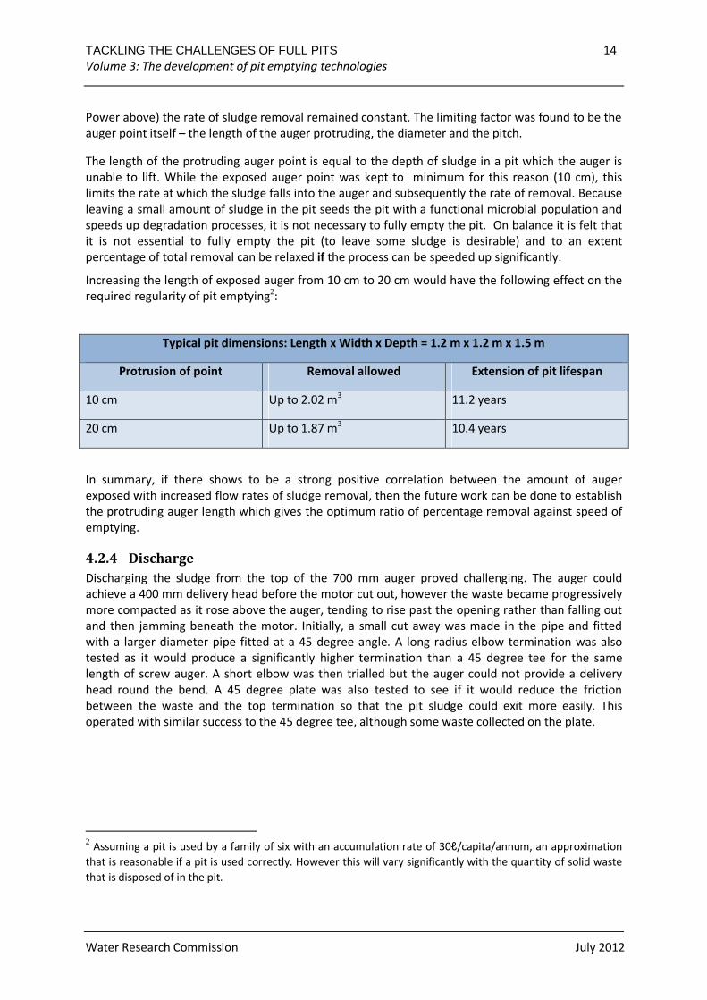
4.2.3 Intake
Testing demonstrated that if the auger protrudes approximately 5-10 cm from the bottom of the
shroud it is better able to take up sludge. While the auger proved able to handle most rubbish
present in the pits, larger objects and rags did occasionally jam the mechanism. A cage was then
added to the bottom of the pipe to prevent larger objects
from being taken up into the auger. However, sludge that
was dense enough to hold its form would not fall into the
cage, making it difficult for the screw to engage the sludge.
In order to improve the flow of sludge toward the auger, the
following modifications were made:
• The length of exposed auger was increased to 15 cm
and the width of this bottom 15 cm of the auger
increased from 3 cm to 5 cm. The aim was to
increase the surface area in order to draw a greater
radius of sludge into the auger while not increasing
the dimensions of the bottom of the screw so much
that sludge would be pushed off the screw where it
enters the sleeve.
• Three blades were added to the bottom of the
screw to increase the auger’s ability to cut through
waste and draw dense waste into the screw.
During testing it was found that even when RPM was doubled from 60 to 120 (described under
Figure 4.4 Blades added to auger point
TACKLING THE CHALLENGES OF FULL PITS 14 Volume 3: The development of pit emptying technologies
Water Research Commission July 2012
Power above) the rate of sludge removal remained constant. The limiting factor was found to be the
auger point itself – the length of the auger protruding, the diameter and the pitch.
The length of the protruding auger point is equal to the depth of sludge in a pit which the auger is
unable to lift. While the exposed auger point was kept to minimum for this reason (10 cm), this
limits the rate at which the sludge falls into the auger and subsequently the rate of removal. Because
leaving a small amount of sludge in the pit seeds the pit with a functional microbial population and
speeds up degradation processes, it is not necessary to fully empty the pit. On balance it is felt that
it is not essential to fully empty the pit (to leave some sludge is desirable) and to an extent
percentage of total removal can be relaxed if the process can be speeded up significantly.
Increasing the length of exposed auger from 10 cm to 20 cm would have the following effect on the
required regularity of pit emptying2:
Typical pit dimensions: Length x Width x Depth = 1.2 m x 1.2 m x 1.5 m
Protrusion of point Removal allowed Extension of pit lifespan
10 cm Up to 2.02 m3 11.2 years
20 cm Up to 1.87 m3 10.4 years
In summary, if there shows to be a strong positive correlation between the amount of auger
exposed with increased flow rates of sludge removal, then the future work can be done to establish
the protruding auger length which gives the optimum ratio of percentage removal against speed of
emptying.
4.2.4 Discharge
Discharging the sludge from the top of the 700 mm auger proved challenging. The auger could
achieve a 400 mm delivery head before the motor cut out, however the waste became progressively
more compacted as it rose above the auger, tending to rise past the opening rather than falling out
and then jamming beneath the motor. Initially, a small cut away was made in the pipe and fitted
with a larger diameter pipe fitted at a 45 degree angle. A long radius elbow termination was also
tested as it would produce a significantly higher termination than a 45 degree tee for the same
length of screw auger. A short elbow was then trialled but the auger could not provide a delivery
head round the bend. A 45 degree plate was also tested to see if it would reduce the friction
between the waste and the top termination so that the pit sludge could exit more easily. This
operated with similar success to the 45 degree tee, although some waste collected on the plate.
2 Assuming a pit is used by a family of six with an accumulation rate of 30ℓ/capita/annum, an approximation
that is reasonable if a pit is used correctly. However this will vary significantly with the quantity of solid waste
that is disposed of in the pit.
TACKLING THE CHALLENGES OF FULL PITS 15 Volume 3: The development of pit emptying technologies
Water Research Commission July 2012
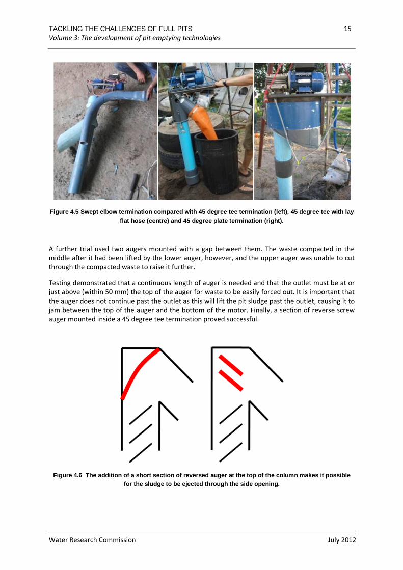
Figure 4.5 Swept elbow termination compared with 45 degree tee termination (left), 45 degree tee with lay flat hose (centre) and 45 degree plate termination (right).
A further trial used two augers mounted with a gap between them. The waste compacted in the
middle after it had been lifted by the lower auger, however, and the upper auger was unable to cut
through the compacted waste to raise it further.
Testing demonstrated that a continuous length of auger is needed and that the outlet must be at or
just above (within 50 mm) the top of the auger for waste to be easily forced out. It is important that
the auger does not continue past the outlet as this will lift the pit sludge past the outlet, causing it to
jam between the top of the auger and the bottom of the motor. Finally, a section of reverse screw
auger mounted inside a 45 degree tee termination proved successful.
Figure 4.6 The addition of a short section of reve rsed auger at the top of the column makes it possib le for the sludge to be ejected through the side openi ng.
TACKLING THE CHALLENGES OF FULL PITS 16 Volume 3: The development of pit emptying technologies
Water Research Commission July 2012
Lay flat hose was used to direct the sludge from the termination of the auger to the collection bin. It
was not always successful as kinks in the hose would sometimes prevent the sludge from
discharging. A piece of heliflex hose was also tested, however pressure built up in the hose and the
sludge was forced upward and eventually the bearing broke, leaving sludge trapped in the hose. A
1 m length of 110 mm flexible pipe attached (and removable for ease of cleaning) to the sludge
outlet at the top of the auger was found to be more successful.
Figure 4.7 Flexible pipe on outlet
Previously sludge dropped from the drop opening, which resulted in difficulty in directing it to a
storage contained. The container and auger had to be held continuously in place to prevent sludge
from dropping back down into the pit (or splashing on to the auger itself creating more mess). The
flexible pipe was fitted to enable sludge to be directed straight into the chosen collection vessel
whilst significantly reducing operator contact with the sludge. In addition, a hook was added from
which to suspend the bucket during emptying.
It was found that before making its way down the pipe sludge built up and was forced out of small
openings in the auger – at the side hole that was left open to aid cleaning and through the top by the
bearing. These holes need to be sealed as much as possible and the pipe should possibly be
shortened to minimise this problem.
4.2.5 Extension
Initially, the shrouding was mounted in such a way that it was modular and extendable. To add the
extension piece, the shrouding had to be removed, the extension screwed on, the shrouding
remounted and a shrouding extension mounted. Since the mechanism measured over 2 meters in
length with the extension, under conditions where a pit was emptied directly through the pedestal it
would have to be coupled with part of the auger in the pit. Clips were used to join the sections as
PVC adapters are not available in 125 mm pipe. These were inexpensive but proved cumbersome to
use and to mount. Fifty millimetre axial slots were cut in the end of the shrouding to enable it to be
slid more easily into a fitting. While the extension almost doubled the length of the auger, the
relative lifting distance was still not very great.
TACKLING THE CHALLENGES OF FULL PITS 17 Volume 3: The development of pit emptying technologies
Water Research Commission July 2012
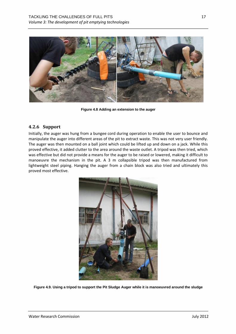
Figure 4.8 Adding an extension to the auger
4.2.6 Support
Initially, the auger was hung from a bungee cord during operation to enable the user to bounce and
manipulate the auger into different areas of the pit to extract waste. This was not very user friendly.
The auger was then mounted on a ball joint which could be lifted up and down on a jack. While this
proved effective, it added clutter to the area around the waste outlet. A tripod was then tried, which
was effective but did not provide a means for the auger to be raised or lowered, making it difficult to
manoeuvre the mechanism in the pit. A 3 m collapsible tripod was then manufactured from
lightweight steel piping. Hanging the auger from a chain block was also tried and ultimately this
proved most effective.
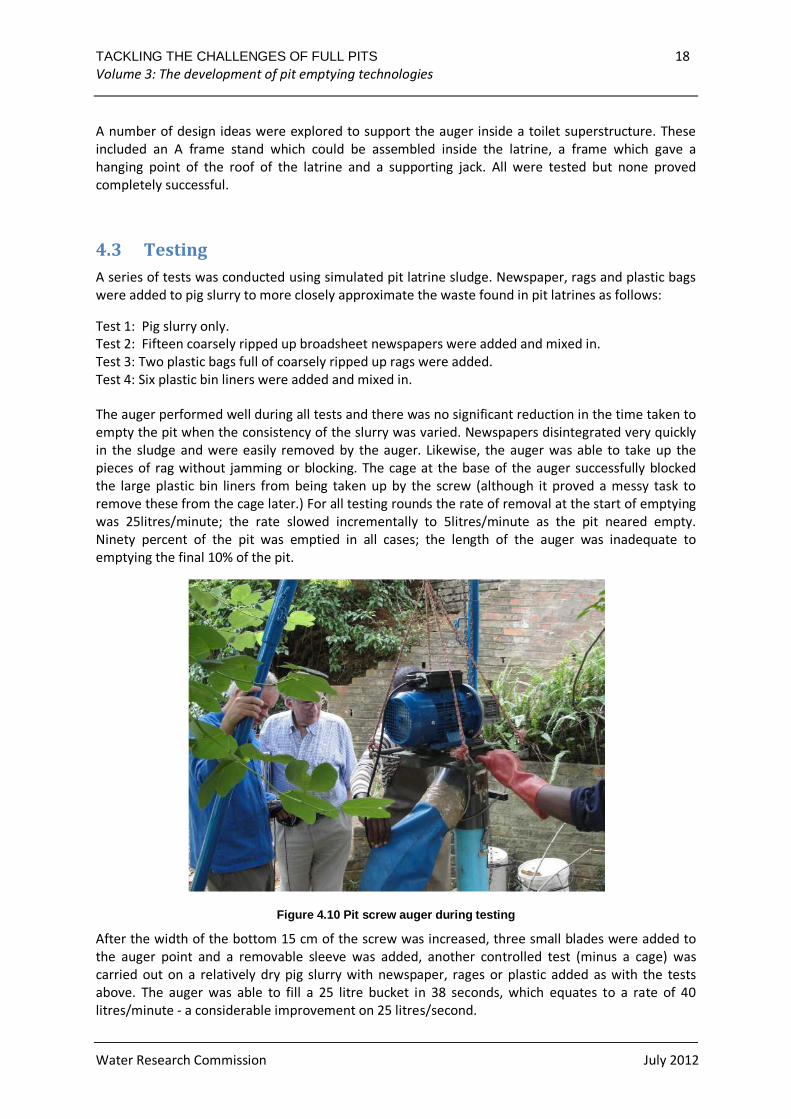
Figure 4.9. Using a tripod to support the Pit Sludg e Auger while it is manoeuvred around the sludge
TACKLING THE CHALLENGES OF FULL PITS 18 Volume 3: The development of pit emptying technologies
Water Research Commission July 2012
A number of design ideas were explored to support the auger inside a toilet superstructure. These
included an A frame stand which could be assembled inside the latrine, a frame which gave a
hanging point of the roof of the latrine and a supporting jack. All were tested but none proved
completely successful.
4.3 Testing
A series of tests was conducted using simulated pit latrine sludge. Newspaper, rags and plastic bags
were added to pig slurry to more closely approximate the waste found in pit latrines as follows:
Test 1: Pig slurry only.
Test 2: Fifteen coarsely ripped up broadsheet newspapers were added and mixed in.
Test 3: Two plastic bags full of coarsely ripped up rags were added.
Test 4: Six plastic bin liners were added and mixed in.
The auger performed well during all tests and there was no significant reduction in the time taken to
empty the pit when the consistency of the slurry was varied. Newspapers disintegrated very quickly
in the sludge and were easily removed by the auger. Likewise, the auger was able to take up the
pieces of rag without jamming or blocking. The cage at the base of the auger successfully blocked
the large plastic bin liners from being taken up by the screw (although it proved a messy task to
remove these from the cage later.) For all testing rounds the rate of removal at the start of emptying
was 25litres/minute; the rate slowed incrementally to 5litres/minute as the pit neared empty.
Ninety percent of the pit was emptied in all cases; the length of the auger was inadequate to
emptying the final 10% of the pit.
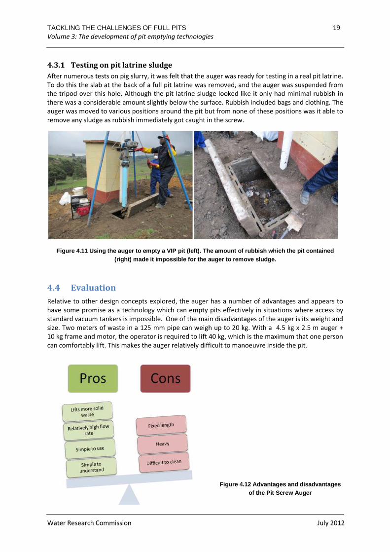
Figure 4.10 Pit screw auger during testing
After the width of the bottom 15 cm of the screw was increased, three small blades were added to
the auger point and a removable sleeve was added, another controlled test (minus a cage) was
carried out on a relatively dry pig slurry with newspaper, rages or plastic added as with the tests
above. The auger was able to fill a 25 litre bucket in 38 seconds, which equates to a rate of 40
litres/minute - a considerable improvement on 25 litres/second.
TACKLING THE CHALLENGES OF FULL PITS 19 Volume 3: The development of pit emptying technologies
Water Research Commission July 2012
4.3.1 Testing on pit latrine sludge
After numerous tests on pig slurry, it was felt that the auger was ready for testing in a real pit latrine.
To do this the slab at the back of a full pit latrine was removed, and the auger was suspended from
the tripod over this hole. Although the pit latrine sludge looked like it only had minimal rubbish in
there was a considerable amount slightly below the surface. Rubbish included bags and clothing. The
auger was moved to various positions around the pit but from none of these positions was it able to
remove any sludge as rubbish immediately got caught in the screw.
Figure 4.11 Using the auger to empty a VIP pit (lef t). The amount of rubbish which the pit contained (right) made it impossible for the auger to remove sludge.
4.4 Evaluation
Relative to other design concepts explored, the auger has a number of advantages and appears to
have some promise as a technology which can empty pits effectively in situations where access by
standard vacuum tankers is impossible. One of the main disadvantages of the auger is its weight and
size. Two meters of waste in a 125 mm pipe can weigh up to 20 kg. With a 4.5 kg x 2.5 m auger +
10 kg frame and motor, the operator is required to lift 40 kg, which is the maximum that one person
can comfortably lift. This makes the auger relatively difficult to manoeuvre inside the pit.
Figure 4.12 Advantages and disadvantages of the Pit Screw Auger
TACKLING THE CHALLENGES OF FULL PITS 20 Volume 3: The development of pit emptying technologies
Water Research Commission July 2012
4.5 Recommendations for further development
• Dealing with rubbish in the pit. The rubbish frequently found in VIP pits presents a real
obstacle to virtually any kind of mechanized device attempting to empty the pit, including
the auger. Some rubbish can be raked out of the pit manually before emptying, but it is
impossible to remove all of the rubbish in this way and the process of removing rubbish can
be messy. A waste shredder could be made to shred everything in the pit before emptying.
• Reduce weight. A smaller diameter auger could greatly reduce the weight of the system, as
could the option of having the motor on the floor, driving the auger via a flexible drive shaft,
or a hydraulic system. As an internal combustion engine has higher power density than an
electric motor, it may be worth considering.
• Improve manoeuvrability. The auger is difficult to manoeuvre due to its large size and
weight. One way this problem could be overcome would be to develop a different
arrangement in which the auger remains stationary and pit emptiers manually direct sludge
to it. This would allow the auger to be quite long and designed simply to deliver the pit
sludge to a spillover dish/pan from where it could be manually slid off into containers. Its
weight would not be problematic as the device would only be carried when empty. This
would also permit a significantly larger engine.
• Modularity. A modular design proved unsuitable as it would bring the operator into contact
with faeces while assembling and disassembling contaminated parts. Better options may be
to have longer and shorter versions of the auger for working at different pit depths, or
incorporating two outlets into the design of a single long unit.
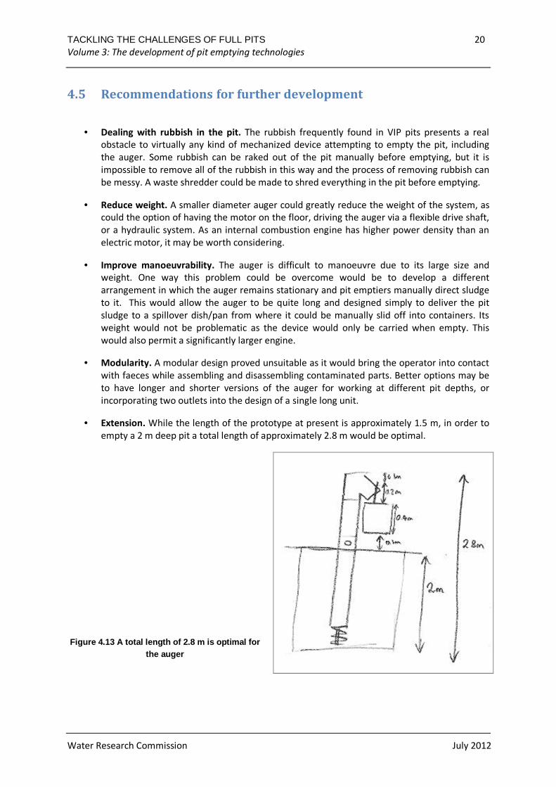
• Extension. While the length of the prototype at present is approximately 1.5 m, in order to
empty a 2 m deep pit a total length of approximately 2.8 m would be optimal.
Figure 4.13 A total length of 2.8 m is optimal for the auger
TACKLING THE CHALLENGES OF FULL PITS 21 Volume 3: The development of pit emptying technologies
Water Research Commission July 2012
Further investigation is needed of ways to reduce contact between operator and the sludge,
particularly during storage, transport and cleaning.
• Storage and Transportation. An appropriate container and method of transportation needs
to be identified to reduce contact between the sludge and workers.
• Cleaning. Cleaning the auger involves unacceptable levels of contact between the worker
and sludge. Specific equipment and products should be explored for cleaning the auger both
at the site where the pit is being emptied and at the end of a day of operation.
• Support. While the tripod provides an adequate support frame for the auger, it does not
allow for the mechanism to be raised or lowered into the pit, making it difficult to
manoeuvre the auger inside the pit. Further consideration also needs to be given to
supporting and manipulating the auger inside of a toilet superstructure.
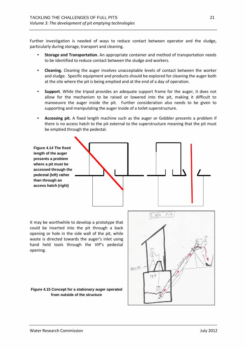
• Accessing pit. A fixed length machine such as the auger or Gobbler presents a problem if
there is no access hatch to the pit external to the superstructure meaning that the pit must
be emptied through the pedestal.
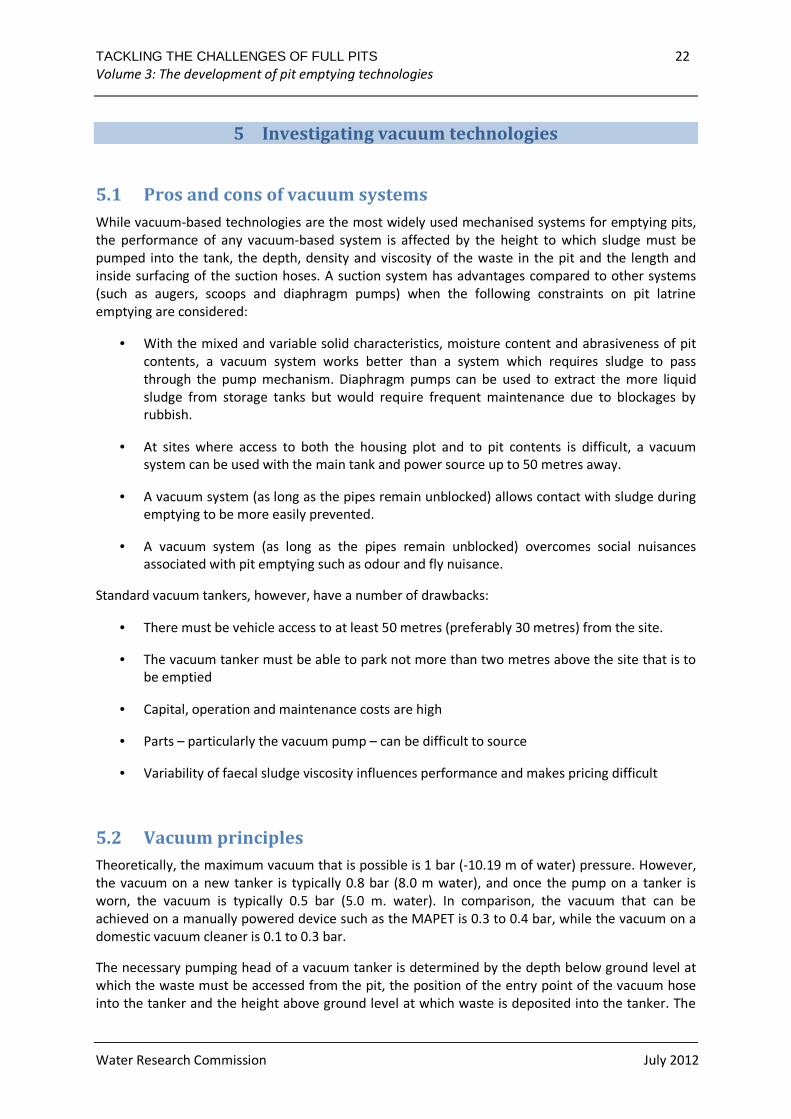
It may be worthwhile to develop a prototype that
could be inserted into the pit through a back
opening or hole in the side wall of the pit, while
waste is directed towards the auger’s inlet using
hand held tools through the VIP’s pedestal
opening.
Figure 4.15 Concept for a stationary auger operated from outside of the structure
Figure 4.14 The fixed length of the auger presents a problem where a pit must be accessed through the pedestal (left) rather than through an access hatch (right)
TACKLING THE CHALLENGES OF FULL PITS 22 Volume 3: The development of pit emptying technologies
Water Research Commission July 2012
5 Investigating vacuum technologies
5.1 Pros and cons of vacuum systems
While vacuum-based technologies are the most widely used mechanised systems for emptying pits,
the performance of any vacuum-based system is affected by the height to which sludge must be
pumped into the tank, the depth, density and viscosity of the waste in the pit and the length and
inside surfacing of the suction hoses. A suction system has advantages compared to other systems
(such as augers, scoops and diaphragm pumps) when the following constraints on pit latrine
emptying are considered:
• With the mixed and variable solid characteristics, moisture content and abrasiveness of pit
contents, a vacuum system works better than a system which requires sludge to pass
through the pump mechanism. Diaphragm pumps can be used to extract the more liquid
sludge from storage tanks but would require frequent maintenance due to blockages by
rubbish.
• At sites where access to both the housing plot and to pit contents is difficult, a vacuum
system can be used with the main tank and power source up to 50 metres away.
• A vacuum system (as long as the pipes remain unblocked) allows contact with sludge during
emptying to be more easily prevented.
• A vacuum system (as long as the pipes remain unblocked) overcomes social nuisances
associated with pit emptying such as odour and fly nuisance.
Standard vacuum tankers, however, have a number of drawbacks:
• There must be vehicle access to at least 50 metres (preferably 30 metres) from the site.
• The vacuum tanker must be able to park not more than two metres above the site that is to
be emptied
• Capital, operation and maintenance costs are high
• Parts – particularly the vacuum pump – can be difficult to source
• Variability of faecal sludge viscosity influences performance and makes pricing difficult
5.2 Vacuum principles
Theoretically, the maximum vacuum that is possible is 1 bar (-10.19 m of water) pressure. However,
the vacuum on a new tanker is typically 0.8 bar (8.0 m water), and once the pump on a tanker is
worn, the vacuum is typically 0.5 bar (5.0 m. water). In comparison, the vacuum that can be
achieved on a manually powered device such as the MAPET is 0.3 to 0.4 bar, while the vacuum on a
domestic vacuum cleaner is 0.1 to 0.3 bar.
The necessary pumping head of a vacuum tanker is determined by the depth below ground level at
which the waste must be accessed from the pit, the position of the entry point of the vacuum hose
into the tanker and the height above ground level at which waste is deposited into the tanker. The
TACKLING THE CHALLENGES OF FULL PITS 23 Volume 3: The development of pit emptying technologies
Water Research Commission July 2012
height of the tanker is therefore critical. As the pit is emptied, three factors combine which reduce
the performance of the tanker:
• Waste is sucked from a greater depth
• The waste level rises as the tanker fills
• The waste density and viscosity of the material that is being sucked increases as lower levels
of the pit where settling has occurred are accessed
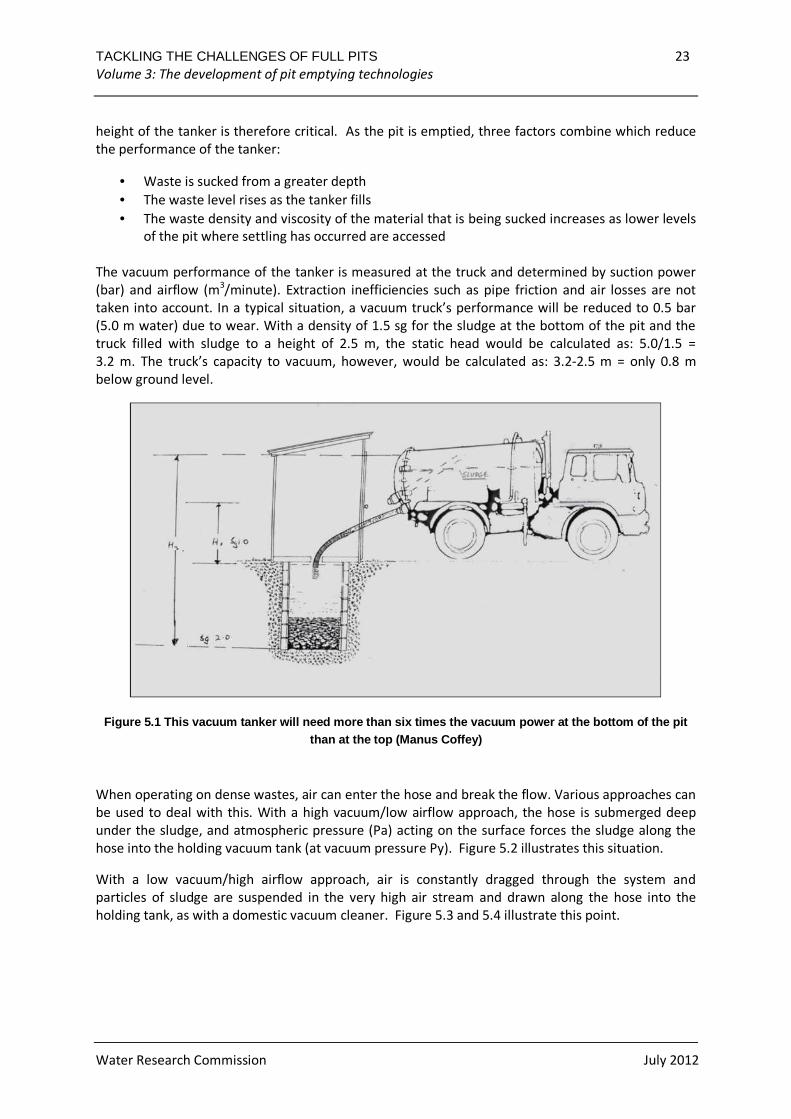
The vacuum performance of the tanker is measured at the truck and determined by suction power
(bar) and airflow (m3/minute). Extraction inefficiencies such as pipe friction and air losses are not
taken into account. In a typical situation, a vacuum truck’s performance will be reduced to 0.5 bar
(5.0 m water) due to wear. With a density of 1.5 sg for the sludge at the bottom of the pit and the
truck filled with sludge to a height of 2.5 m, the static head would be calculated as: 5.0/1.5 =
3.2 m. The truck’s capacity to vacuum, however, would be calculated as: 3.2-2.5 m = only 0.8 m
below ground level.
Figure 5.1 This vacuum tanker will need more than s ix times the vacuum power at the bottom of the pit than at the top (Manus Coffey)
When operating on dense wastes, air can enter the hose and break the flow. Various approaches can
be used to deal with this. With a high vacuum/low airflow approach, the hose is submerged deep
under the sludge, and atmospheric pressure (Pa) acting on the surface forces the sludge along the
hose into the holding vacuum tank (at vacuum pressure Py). Figure 5.2 illustrates this situation.
With a low vacuum/high airflow approach, air is constantly dragged through the system and
particles of sludge are suspended in the very high air stream and drawn along the hose into the
holding tank, as with a domestic vacuum cleaner. Figure 5.3 and 5.4 illustrate this point.
TACKLING THE CHALLENGES OF FULL PITS 24 Volume 3: The development of pit emptying technologies
Water Research Commission July 2012
Figure 5.2 Air can enter the hose and break the flo w when vacuuming dry sludge (Manus Coffey)
Figure 5.4 Air drag system with a low vacuum/high a irflow approach (Manus Coffey)
Figure 5.3 High vacuum/low airflow approach (Manus Coffey)
TACKLING THE CHALLENGES OF FULL PITS 25 Volume 3: The development of pit emptying technologies
Water Research Commission July 2012
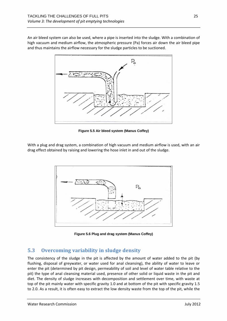
An air bleed system can also be used, where a pipe is inserted into the sludge. With a combination of
high vacuum and medium airflow, the atmospheric pressure (Pa) forces air down the air bleed pipe
and thus maintains the airflow necessary for the sludge particles to be suctioned.
Figure 5.5 Air bleed system (Manus Coffey)
With a plug and drag system, a combination of high vacuum and medium airflow is used, with an air
drag effect obtained by raising and lowering the hose inlet in and out of the sludge.
Figure 5.6 Plug and drag system (Manus Coffey)
5.3 Overcoming variability in sludge density
The consistency of the sludge in the pit is affected by the amount of water added to the pit (by
flushing, disposal of greywater, or water used for anal cleansing), the ability of water to leave or
enter the pit (determined by pit design, permeability of soil and level of water table relative to the
pit) the type of anal cleansing material used, presence of other solid or liquid waste in the pit and
diet. The density of sludge increases with decomposition and settlement over time, with waste at
top of the pit mainly water with specific gravity 1.0 and at bottom of the pit with specific gravity 1.5
to 2.0. As a result, it is often easy to extract the low density waste from the top of the pit, while the
TACKLING THE CHALLENGES OF FULL PITS 26 Volume 3: The development of pit emptying technologies
Water Research Commission July 2012
high density sludge which progressively builds up at the bottom becomes increasing difficult to
remove.
In trials of various vacuum based machines, Manus Coffey and Associates found that sludge that is
less than a year old is generally easy to remove by suction (Coffey, pers. comm). Sludge that is more
than two years old is often too dry and dense to be removed by suction. Attempts to fluidize older
sludge by adding water to the top were unsuccessful as the water simply floated at the top. Because
vacuum tanker operators often cannot remove the densest sludge from the bottom of the pit, it
builds up, reducing the volume of the pit over time. This is exacerbated when householders cannot
afford to have their large pits emptied completely and only have the top, lower density waste
removed.
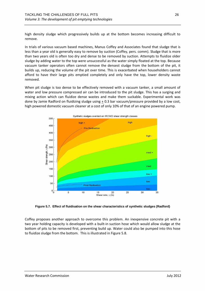
When pit sludge is too dense to be effectively removed with a vacuum tanker, a small amount of
water and low pressure compressed air can be introduced to the pit sludge. This has a surging and
mixing action which can fluidize dense wastes and make them suckable. Experimental work was
done by Jamie Radford on fluidizing sludge using + 0.3 bar vacuum/pressure provided by a low cost,
high powered domestic vacuum cleaner at a cost of only 10% of that of an engine powered pump.
Figure 5.7. Effect of fluidisation on the shear ch aracteristics of synthetic sludges (Radford)
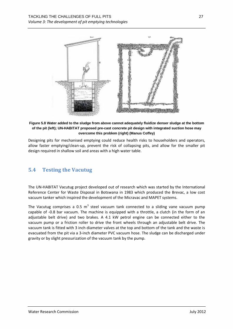
Coffey proposes another approach to overcome this problem. An inexpensive concrete pit with a
two year holding capacity is developed with a built-in suction hose which would allow sludge at the
bottom of pits to be removed first, preventing build up. Water could also be pumped into this hose
to fluidize sludge from the bottom. This is illustrated in Figure 5.8.
TACKLING THE CHALLENGES OF FULL PITS 27 Volume 3: The development of pit emptying technologies
Water Research Commission July 2012
Figure 5.8 Water added to the sludge from above can not adequately fluidize denser sludge at the bottom of the pit (left); UN-HABITAT proposed pre-cast con crete pit design with integrated suction hose may
overcome this problem (right) (Manus Coffey)
Designing pits for mechanised emptying could reduce health risks to householders and operators,
allow faster emptying/clean-up, prevent the risk of collapsing pits, and allow for the smaller pit
design required in shallow soil and areas with a high water table.
5.4 Testing the Vacutug
The UN-HABITAT Vacutug project developed out of research which was started by the International
Reference Center for Waste Disposal in Botswana in 1983 which produced the Brevac, a low cost
vacuum tanker which inspired the development of the Micravac and MAPET systems.
The Vacutug comprises a 0.5 m3 steel vacuum tank connected to a sliding vane vacuum pump
capable of -0.8 bar vacuum. The machine is equipped with a throttle, a clutch (in the form of an
adjustable belt drive) and two brakes. A 4.1 kW petrol engine can be connected either to the
vacuum pump or a friction roller to drive the front wheels through an adjustable belt drive. The
vacuum tank is fitted with 3 inch diameter valves at the top and bottom of the tank and the waste is
evacuated from the pit via a 3-inch diameter PVC vacuum hose. The sludge can be discharged under
gravity or by slight pressurization of the vacuum tank by the pump.
TACKLING THE CHALLENGES OF FULL PITS 28 Volume 3: The development of pit emptying technologies
Water Research Commission July 2012
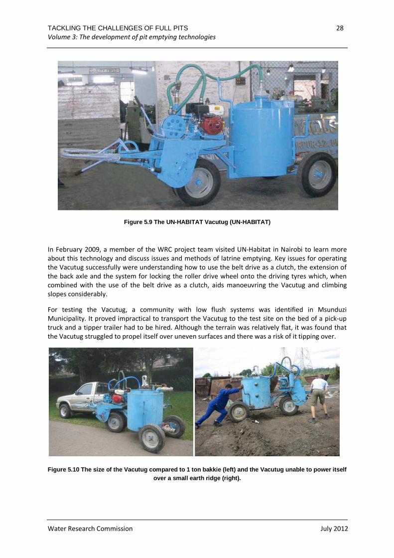
Figure 5.9 The UN-HABITAT Vacutug (UN-HABITAT)
In February 2009, a member of the WRC project team visited UN-Habitat in Nairobi to learn more
about this technology and discuss issues and methods of latrine emptying. Key issues for operating
the Vacutug successfully were understanding how to use the belt drive as a clutch, the extension of
the back axle and the system for locking the roller drive wheel onto the driving tyres which, when
combined with the use of the belt drive as a clutch, aids manoeuvring the Vacutug and climbing
slopes considerably.
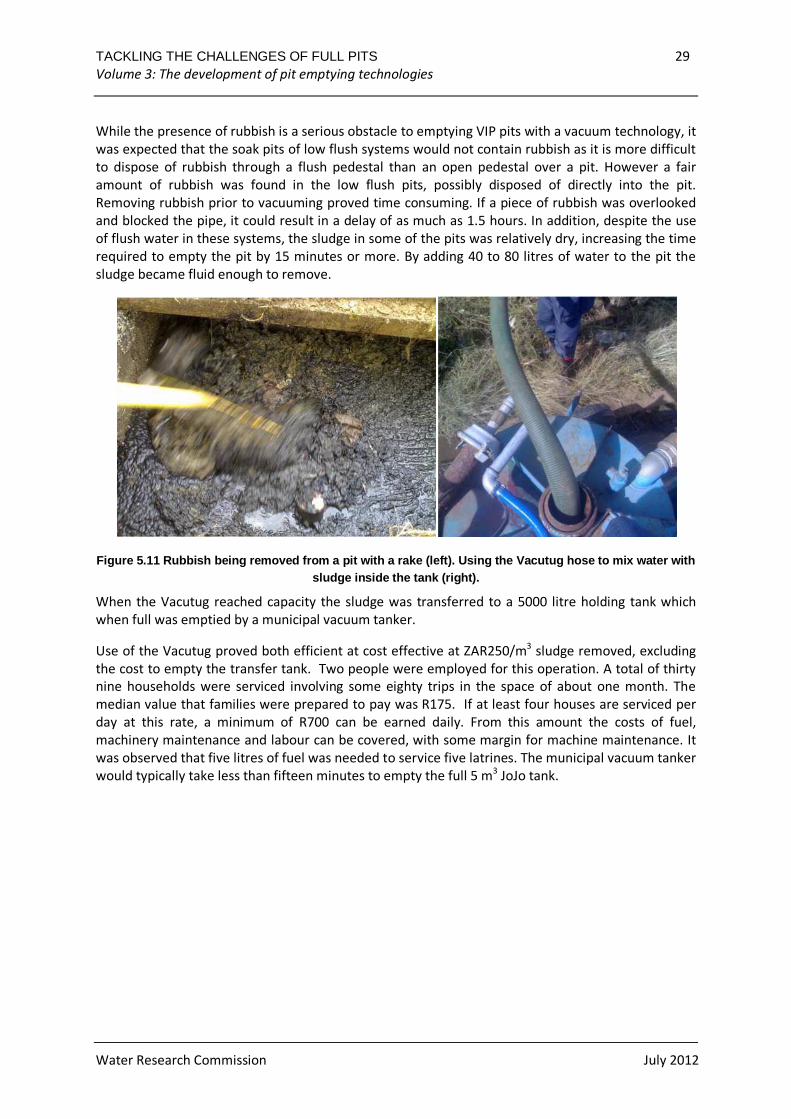
For testing the Vacutug, a community with low flush systems was identified in Msunduzi
Municipality. It proved impractical to transport the Vacutug to the test site on the bed of a pick-up
truck and a tipper trailer had to be hired. Although the terrain was relatively flat, it was found that
the Vacutug struggled to propel itself over uneven surfaces and there was a risk of it tipping over.
Figure 5.10 The size of the Vacutug compared to 1 t on bakkie (left) and the Vacutug unable to power it self over a small earth ridge (right).
TACKLING THE CHALLENGES OF FULL PITS 29 Volume 3: The development of pit emptying technologies
Water Research Commission July 2012
While the presence of rubbish is a serious obstacle to emptying VIP pits with a vacuum technology, it
was expected that the soak pits of low flush systems would not contain rubbish as it is more difficult
to dispose of rubbish through a flush pedestal than an open pedestal over a pit. However a fair
amount of rubbish was found in the low flush pits, possibly disposed of directly into the pit.
Removing rubbish prior to vacuuming proved time consuming. If a piece of rubbish was overlooked
and blocked the pipe, it could result in a delay of as much as 1.5 hours. In addition, despite the use
of flush water in these systems, the sludge in some of the pits was relatively dry, increasing the time
required to empty the pit by 15 minutes or more. By adding 40 to 80 litres of water to the pit the
sludge became fluid enough to remove.
Figure 5.11 Rubbish being removed from a pit with a rake (left). Using the Vacutug hose to mix water w ith sludge inside the tank (right).
When the Vacutug reached capacity the sludge was transferred to a 5000 litre holding tank which
when full was emptied by a municipal vacuum tanker.
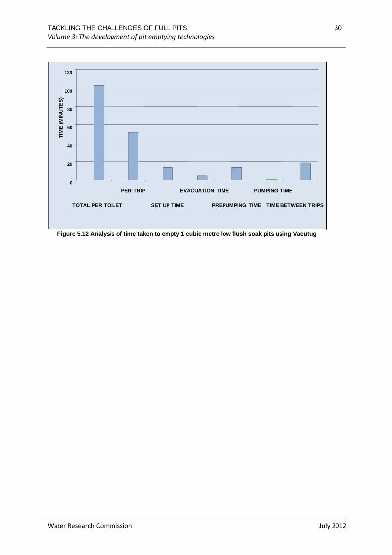
Use of the Vacutug proved both efficient at cost effective at ZAR250/m3 sludge removed, excluding
the cost to empty the transfer tank. Two people were employed for this operation. A total of thirty
nine households were serviced involving some eighty trips in the space of about one month. The
median value that families were prepared to pay was R175. If at least four houses are serviced per
day at this rate, a minimum of R700 can be earned daily. From this amount the costs of fuel,
machinery maintenance and labour can be covered, with some margin for machine maintenance. It
was observed that five litres of fuel was needed to service five latrines. The municipal vacuum tanker
would typically take less than fifteen minutes to empty the full 5 m3 JoJo tank.
TACKLING THE CHALLENGES OF FULL PITS 30 Volume 3: The development of pit emptying technologies
Water Research Commission July 2012
0
20
40
60
80
100
120
TOTAL PER TOILET
PER TRIP
SET UP TIME
EVACUATION TIME
PREPUMPING TIME
PUMPING TIME
TIME BETWEEN TRIPS
TIM
E (
MIN
UT
ES
)
Figure 5.12 Analysis of time taken to empty 1 cubic metre low flush soak pits using Vacutug
TACKLING THE CHALLENGES OF FULL PITS 31 Volume 3: The development of pit emptying technologies
Water Research Commission July 2012
6 THE NANO VAC
The development of the MAPET system in Dar es Salaam in 1990s, though ultimately unsuccessful,
proved that piston pumps can achieve the vacuum pressures required for sucking liquid wastes out
of latrine pits, creating possibilities for low-cost vacuum technologies which could work in parallel
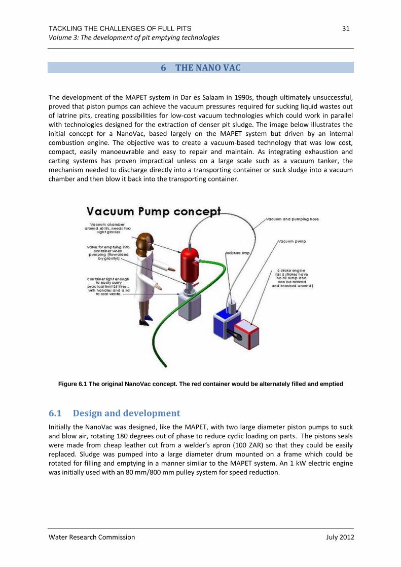
with technologies designed for the extraction of denser pit sludge. The image below illustrates the
initial concept for a NanoVac, based largely on the MAPET system but driven by an internal
combustion engine. The objective was to create a vacuum-based technology that was low cost,
compact, easily manoeuvrable and easy to repair and maintain. As integrating exhaustion and
carting systems has proven impractical unless on a large scale such as a vacuum tanker, the
mechanism needed to discharge directly into a transporting container or suck sludge into a vacuum
chamber and then blow it back into the transporting container.
Figure 6.1 The original NanoVac concept. The red co ntainer would be alternately filled and emptied
6.1 Design and development
Initially the NanoVac was designed, like the MAPET, with two large diameter piston pumps to suck
and blow air, rotating 180 degrees out of phase to reduce cyclic loading on parts. The pistons seals
were made from cheap leather cut from a welder’s apron (100 ZAR) so that they could be easily
replaced. Sludge was pumped into a large diameter drum mounted on a frame which could be
rotated for filling and emptying in a manner similar to the MAPET system. An 1 kW electric engine
was initially used with an 80 mm/800 mm pulley system for speed reduction.
TACKLING THE CHALLENGES OF FULL PITS 32 Volume 3: The development of pit emptying technologies
Water Research Commission July 2012
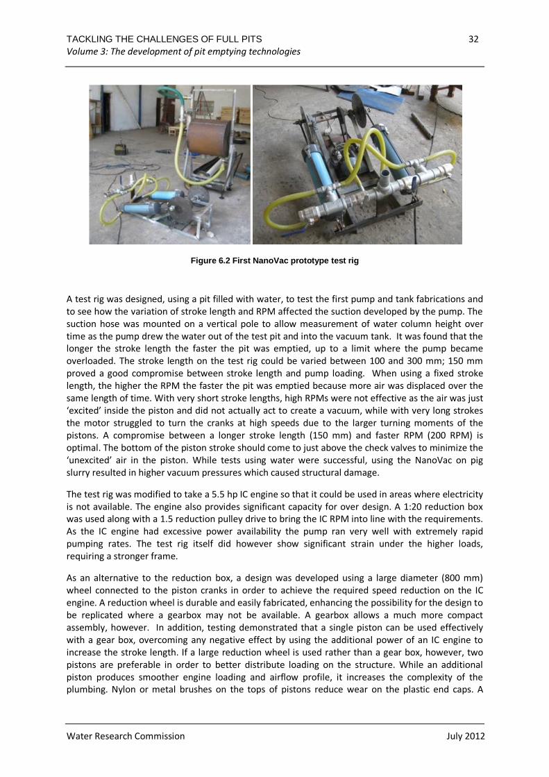
Figure 6.2 First NanoVac prototype test rig
A test rig was designed, using a pit filled with water, to test the first pump and tank fabrications and
to see how the variation of stroke length and RPM affected the suction developed by the pump. The
suction hose was mounted on a vertical pole to allow measurement of water column height over
time as the pump drew the water out of the test pit and into the vacuum tank. It was found that the
longer the stroke length the faster the pit was emptied, up to a limit where the pump became
overloaded. The stroke length on the test rig could be varied between 100 and 300 mm; 150 mm
proved a good compromise between stroke length and pump loading. When using a fixed stroke
length, the higher the RPM the faster the pit was emptied because more air was displaced over the
same length of time. With very short stroke lengths, high RPMs were not effective as the air was just
‘excited’ inside the piston and did not actually act to create a vacuum, while with very long strokes
the motor struggled to turn the cranks at high speeds due to the larger turning moments of the
pistons. A compromise between a longer stroke length (150 mm) and faster RPM (200 RPM) is
optimal. The bottom of the piston stroke should come to just above the check valves to minimize the
‘unexcited’ air in the piston. While tests using water were successful, using the NanoVac on pig
slurry resulted in higher vacuum pressures which caused structural damage.
The test rig was modified to take a 5.5 hp IC engine so that it could be used in areas where electricity
is not available. The engine also provides significant capacity for over design. A 1:20 reduction box
was used along with a 1.5 reduction pulley drive to bring the IC RPM into line with the requirements.
As the IC engine had excessive power availability the pump ran very well with extremely rapid
pumping rates. The test rig itself did however show significant strain under the higher loads,
requiring a stronger frame.
As an alternative to the reduction box, a design was developed using a large diameter (800 mm)
wheel connected to the piston cranks in order to achieve the required speed reduction on the IC
engine. A reduction wheel is durable and easily fabricated, enhancing the possibility for the design to
be replicated where a gearbox may not be available. A gearbox allows a much more compact
assembly, however. In addition, testing demonstrated that a single piston can be used effectively
with a gear box, overcoming any negative effect by using the additional power of an IC engine to
increase the stroke length. If a large reduction wheel is used rather than a gear box, however, two
pistons are preferable in order to better distribute loading on the structure. While an additional
piston produces smoother engine loading and airflow profile, it increases the complexity of the
plumbing. Nylon or metal brushes on the tops of pistons reduce wear on the plastic end caps. A
TACKLING THE CHALLENGES OF FULL PITS 33 Volume 3: The development of pit emptying technologies
Water Research Commission July 2012
flywheel may be useful to smooth the cyclic loading of the pistons, although it would increase the
weight and size of the pump.
During the development of the Nano Vac, the number of gate valves in the plumbing was reduced by
using separate pumping and vacuum hoses. Venting gate valves (especially the blow line) were
placed at ergonomic heights and vented downward. The moisture trap was removed as no moisture
was seen in the system during the initial tests; however as dirt can be sucked into the mechanism a
PVC moisture trap may be beneficial. Plumbing was simplified over the course of development and
one inch hosing and fittings were eventually used throughout. Hoses were kept high off the ground
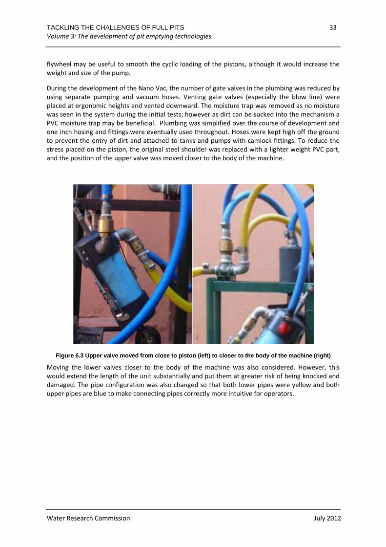
to prevent the entry of dirt and attached to tanks and pumps with camlock fittings. To reduce the
stress placed on the piston, the original steel shoulder was replaced with a lighter weight PVC part,
and the position of the upper valve was moved closer to the body of the machine.
Figure 6.3 Upper valve moved from close to piston ( left) to closer to the body of the machine (right)
Moving the lower valves closer to the body of the machine was also considered. However, this
would extend the length of the unit substantially and put them at greater risk of being knocked and
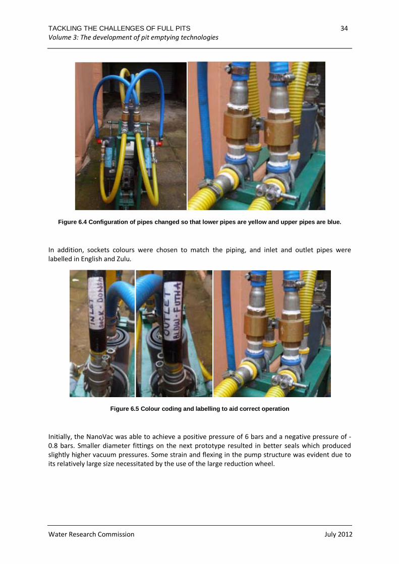
damaged. The pipe configuration was also changed so that both lower pipes were yellow and both
upper pipes are blue to make connecting pipes correctly more intuitive for operators.
TACKLING THE CHALLENGES OF FULL PITS 34 Volume 3: The development of pit emptying technologies
Water Research Commission July 2012
Figure 6.4 Configuration of pipes changed so that l ower pipes are yellow and upper pipes are blue.
In addition, sockets colours were chosen to match the piping, and inlet and outlet pipes were
labelled in English and Zulu.
Figure 6.5 Colour coding and labelling to aid corre ct operation
Initially, the NanoVac was able to achieve a positive pressure of 6 bars and a negative pressure of -
0.8 bars. Smaller diameter fittings on the next prototype resulted in better seals which produced
slightly higher vacuum pressures. Some strain and flexing in the pump structure was evident due to
its relatively large size necessitated by the use of the large reduction wheel.
TACKLING THE CHALLENGES OF FULL PITS 35 Volume 3: The development of pit emptying technologies
Water Research Commission July 2012
6.1.1 Pump
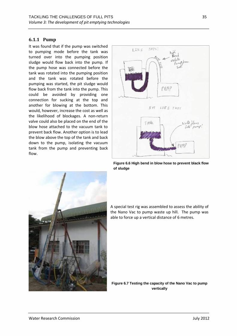
It was found that if the pump was switched
to pumping mode before the tank was
turned over into the pumping position
sludge would flow back into the pump. If
the pump hose was connected before the
tank was rotated into the pumping position
and the tank was rotated before the
pumping was started, the pit sludge would
flow back from the tank into the pump. This
could be avoided by providing one
connection for sucking at the top and
another for blowing at the bottom. This
would, however, increase the cost as well as
the likelihood of blockages. A non-return
valve could also be placed on the end of the
blow hose attached to the vacuum tank to
prevent back flow. Another option is to lead
the blow above the top of the tank and back
down to the pump, isolating the vacuum
tank from the pump and preventing back
flow.
Figure 6.6 High bend in blow hose to prevent black flow of sludge
A special test rig was assembled to assess the ability of
the Nano Vac to pump waste up hill. The pump was
able to force up a vertical distance of 6 metres.
Figure 6.7 Testing the capacity of the Nano Vac to pump vertically
TACKLING THE CHALLENGES OF FULL PITS 36 Volume 3: The development of pit emptying technologies
Water Research Commission July 2012
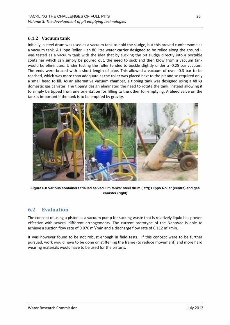
6.1.2 Vacuum tank
Initially, a steel drum was used as a vacuum tank to hold the sludge, but this proved cumbersome as
a vacuum tank. A Hippo Roller – an 80 litre water carrier designed to be rolled along the ground –
was tested as a vacuum tank with the idea that by sucking the pit sludge directly into a portable
container which can simply be poured out, the need to suck and then blow from a vacuum tank
would be eliminated. Under testing the roller tended to buckle slightly under a -0.25 bar vacuum.
The ends were braced with a short length of pipe. This allowed a vacuum of over -0.3 bar to be
reached, which was more than adequate as the roller was placed next to the pit and so required only
a small head to fill. As an alternative vacuum chamber, a tipping tank was designed using a 48 kg
domestic gas canister. The tipping design eliminated the need to rotate the tank, instead allowing it
to simply be tipped from one orientation for filling to the other for emptying. A bleed valve on the
tank is important if the tank is to be emptied by gravity.
Figure 6.8 Various containers trialled as vacuum ta nks: steel drum (left); Hippo Roller (centre) and g as canister (right)
6.2 Evaluation
The concept of using a piston as a vacuum pump for sucking waste that is relatively liquid has proven
effective with several different arrangements. The current prototype of the NanoVac is able to
achieve a suction flow rate of 0.076 m3/min and a discharge flow rate of 0.112 m3/min.
It was however found to be not robust enough in field tests. If this concept were to be further
pursued, work would have to be done on stiffening the frame (to reduce movement) and more hard
wearing materials would have to be used for the pistons.
TACKLING THE CHALLENGES OF FULL PITS 37 Volume 3: The development of pit emptying technologies
Water Research Commission July 2012
Figure 6.9 Current Nano Vac prototype
Figure 6.10 Advantages and disadvantages of NanoVac in comparison to other pit emptying technologies
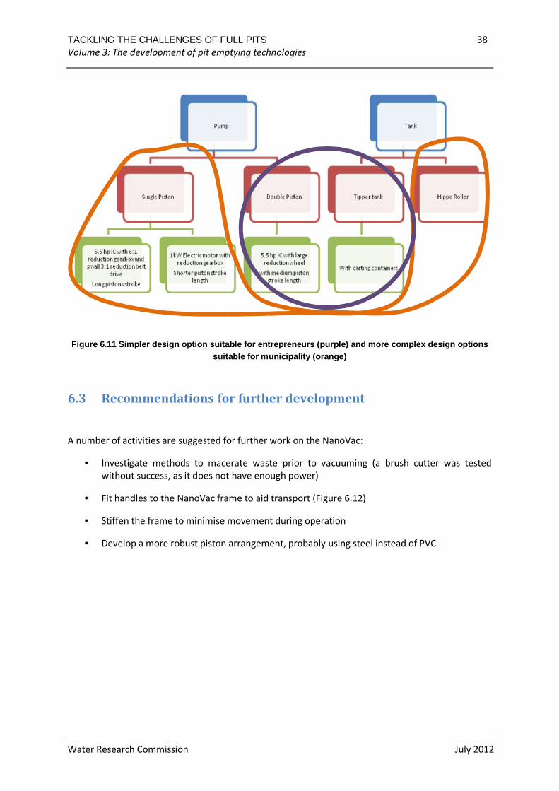
Different design options may prove optimal for different contexts. In Figure 6.11 a tank and pump
combination that would be appropriate for an entrepreneurial group in a situation with poor access
to engineered components and processes is circled in purple. Two approaches which are more
appropriate for a municipal pit emptying programme where complex engineering processes and
components are available are circled in orange.
TACKLING THE CHALLENGES OF FULL PITS 38 Volume 3: The development of pit emptying technologies
Water Research Commission July 2012
Figure 6.11 Simpler design option suitable for entr epreneurs (purple) and more complex design options suitable for municipality (orange)
6.3 Recommendations for further development
A number of activities are suggested for further work on the NanoVac:
• Investigate methods to macerate waste prior to vacuuming (a brush cutter was tested
without success, as it does not have enough power)
• Fit handles to the NanoVac frame to aid transport (Figure 6.12)
• Stiffen the frame to minimise movement during operation
• Develop a more robust piston arrangement, probably using steel instead of PVC
TACKLING THE CHALLENGES OF FULL PITS 39 Volume 3: The development of pit emptying technologies
Water Research Commission July 2012
Figure 6.12 Sketch of Nano Vac with handles
It has also been suggested that blowing waste out of the pit may be possible. Therefore testing with
both the blowing and sucking hoses in the pit may be interesting to see if the blowing air can help to
suck the waste out.
TACKLING THE CHALLENGES OF FULL PITS 40 Volume 3: The development of pit emptying technologies
Water Research Commission July 2012
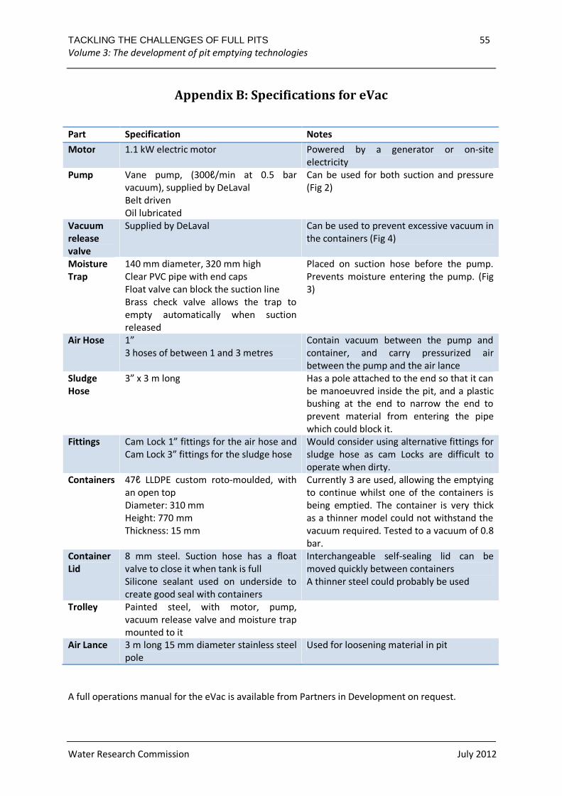
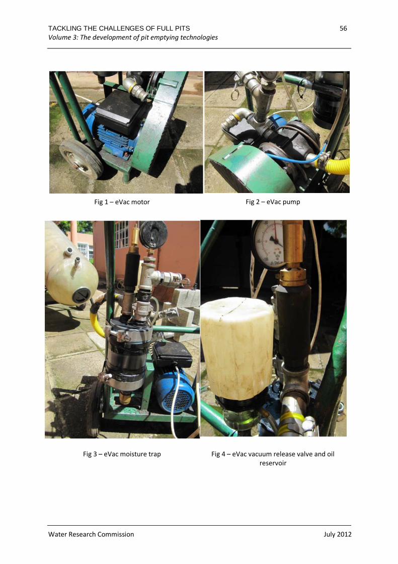
7 THE EVAC
The eVac was developed on the same principle as the NanoVac: a vacuum is created in a container
which in turn sucks up sludge from a pit. However a vane pump was used rather than a piston pump.
The pump and a 1.5 kW electric motor, powered by a generator, were mounted on a custom
fabricated steel trolley and connected by a belt drive. The oil supply for the pump was mounted
above it, as were the vacuum relief valve and the moisture trap. A float valve, made from a squash
ball, closed the vacuum line when the container was full in order to prevent sludge from being
sucked into the pump. Despite the trolley unit weighing a total of 63 kg the trolley was
manoeuvrable, was capable of being moved easily across rough ground and could be lifted onto a
vehicle by two people. The trolley was also stable when standing upright because the pump and
motor were mounted low down on the trolley. A manual for the manufacturing and operation of
the eVac can be found on the Partners in Development website (www.pid.co.za).
7.1 Prototype development
The e Vac was designed and developed to meet the
criteria that it must be:
• simple to use
• light enough to be transported to the work
site on an ordinary pick-up truck
• light enough for two people to transport on
site over rough ground without great effort
• affordable for use in a pit latrine emptying
project
• adequately versatile to remove a range of
sludges (including those containing some
rubbish) from a range of pit latrines
• designed to minimise the risk of workers
coming into contact with sludge and of
contamination of the work environment by
sludge
• possible to manufacture and maintain using
parts and skills that are locally available in a
developing country
Figure 7.1 The eVac
TACKLING THE CHALLENGES OF FULL PITS 41 Volume 3: The development of pit emptying technologies
Water Research Commission July 2012
7.1.1 Motor
The e Vac was powered by a 1.5 kW (2HP) single phase electric motor with an attached control box.
A short 2.5 mm power cable was used in order to prevent catching on objects, which was used with
a separate extension cord. The motor required a standard 230V power source and for this a
generator could be used if a nearby power source was not available. A petrol engine could have
been used to overcome the need for a power source, but this would have made the eVac less
manageable and more susceptible to damage. A governor would have been needed to ensure that
the pump would turn at a fairly constant rate.
7.1.2 Pump
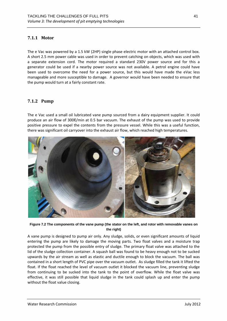
The e Vac used a small oil lubricated vane pump sourced from a dairy equipment supplier. It could
produce an air flow of 300ℓ/min at 0.5 bar vacuum. The exhaust of the pump was used to provide
positive pressure to expel the contents from the pressure vessel. While this was a useful function,
there was significant oil carryover into the exhaust air flow, which reached high temperatures.
Figure 7.2 The components of the vane pump (the sta tor on the left, and rotor with removable vanes on the right)
A vane pump is designed to pump air only. Any sludge, solids, or even significant amounts of liquid
entering the pump are likely to damage the moving parts. Two float valves and a moisture trap
protected the pump from the possible entry of sludge. The primary float valve was attached to the
lid of the sludge collection container. A squash ball was found to be heavy enough not to be sucked
upwards by the air stream as well as elastic and ductile enough to block the vacuum. The ball was
contained in a short length of PVC pipe over the vacuum outlet. As sludge filled the tank it lifted the
float. If the float reached the level of vacuum outlet it blocked the vacuum line, preventing sludge
from continuing to be sucked into the tank to the point of overflow. While the float valve was
effective, it was still possible that liquid sludge in the tank could splash up and enter the pump
without the float value closing.
TACKLING THE CHALLENGES OF FULL PITS 42 Volume 3: The development of pit emptying technologies
Water Research Commission July 2012
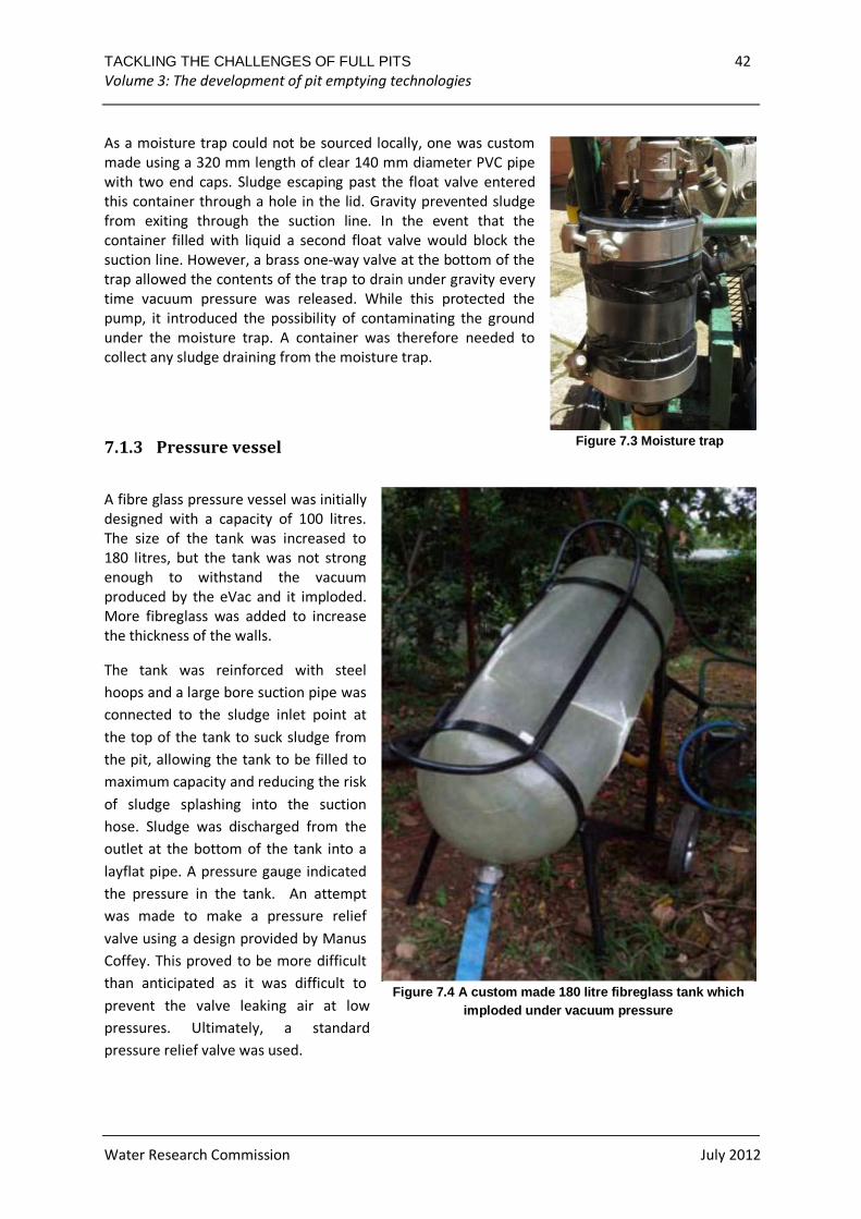
As a moisture trap could not be sourced locally, one was custom
made using a 320 mm length of clear 140 mm diameter PVC pipe
with two end caps. Sludge escaping past the float valve entered
this container through a hole in the lid. Gravity prevented sludge
from exiting through the suction line. In the event that the
container filled with liquid a second float valve would block the
suction line. However, a brass one-way valve at the bottom of the
trap allowed the contents of the trap to drain under gravity every
time vacuum pressure was released. While this protected the
pump, it introduced the possibility of contaminating the ground
under the moisture trap. A container was therefore needed to
collect any sludge draining from the moisture trap.
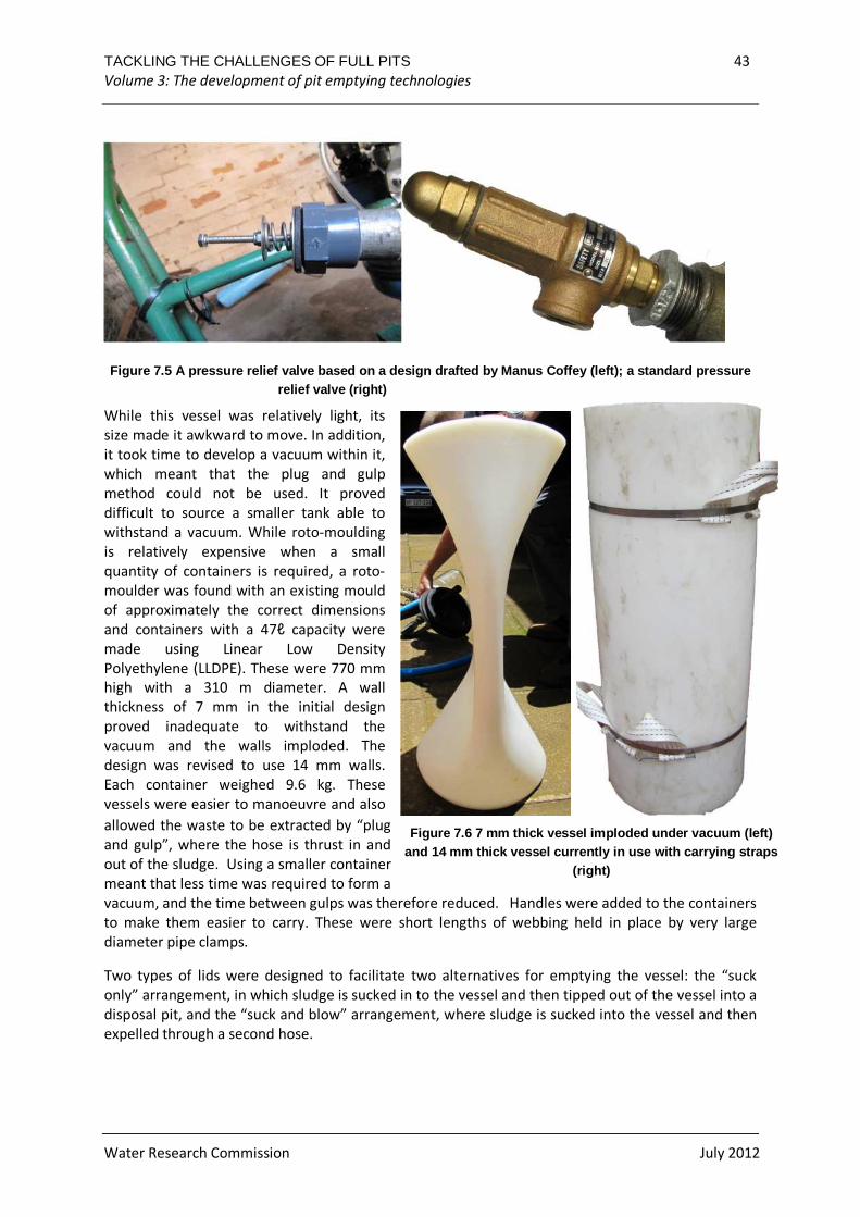
7.1.3 Pressure vessel
A fibre glass pressure vessel was initially
designed with a capacity of 100 litres.
The size of the tank was increased to
180 litres, but the tank was not strong
enough to withstand the vacuum
produced by the eVac and it imploded.
More fibreglass was added to increase
the thickness of the walls.
The tank was reinforced with steel
hoops and a large bore suction pipe was
connected to the sludge inlet point at
the top of the tank to suck sludge from
the pit, allowing the tank to be filled to
maximum capacity and reducing the risk
of sludge splashing into the suction
hose. Sludge was discharged from the
outlet at the bottom of the tank into a
layflat pipe. A pressure gauge indicated
the pressure in the tank. An attempt
was made to make a pressure relief
valve using a design provided by Manus
Coffey. This proved to be more difficult
than anticipated as it was difficult to
prevent the valve leaking air at low
pressures. Ultimately, a standard
pressure relief valve was used.
Figure 7.3 Moisture trap
Figure 7.4 A custom made 180 litre fibreglass tank which imploded under vacuum pressure
TACKLING THE CHALLENGES OF FULL PITS 43 Volume 3: The development of pit emptying technologies
Water Research Commission July 2012
Figure 7.5 A pressure relief valve based on a desig n drafted by Manus Coffey (left); a standard pressu re relief valve (right)
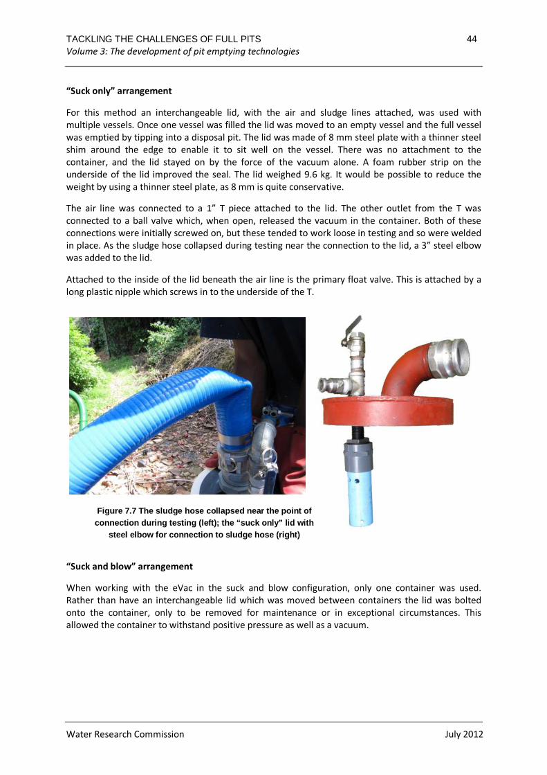
While this vessel was relatively light, its
size made it awkward to move. In addition,
it took time to develop a vacuum within it,
which meant that the plug and gulp
method could not be used. It proved
difficult to source a smaller tank able to
withstand a vacuum. While roto-moulding
is relatively expensive when a small
quantity of containers is required, a roto-
moulder was found with an existing mould
of approximately the correct dimensions
and containers with a 47ℓ capacity were
made using Linear Low Density
Polyethylene (LLDPE). These were 770 mm
high with a 310 m diameter. A wall
thickness of 7 mm in the initial design
proved inadequate to withstand the
vacuum and the walls imploded. The
design was revised to use 14 mm walls.
Each container weighed 9.6 kg. These
vessels were easier to manoeuvre and also
allowed the waste to be extracted by “plug
and gulp”, where the hose is thrust in and
out of the sludge. Using a smaller container
meant that less time was required to form a
vacuum, and the time between gulps was therefore reduced. Handles were added to the containers
to make them easier to carry. These were short lengths of webbing held in place by very large
diameter pipe clamps.
Two types of lids were designed to facilitate two alternatives for emptying the vessel: the “suck
only” arrangement, in which sludge is sucked in to the vessel and then tipped out of the vessel into a
disposal pit, and the “suck and blow” arrangement, where sludge is sucked into the vessel and then
expelled through a second hose.
Figure 7.6 7 mm thick vessel imploded under vacuum (left) and 14 mm thick vessel currently in use with carrying stra ps
(right)
TACKLING THE CHALLENGES OF FULL PITS 44 Volume 3: The development of pit emptying technologies
Water Research Commission July 2012
“Suck only” arrangement
For this method an interchangeable lid, with the air and sludge lines attached, was used with
multiple vessels. Once one vessel was filled the lid was moved to an empty vessel and the full vessel
was emptied by tipping into a disposal pit. The lid was made of 8 mm steel plate with a thinner steel
shim around the edge to enable it to sit well on the vessel. There was no attachment to the
container, and the lid stayed on by the force of the vacuum alone. A foam rubber strip on the
underside of the lid improved the seal. The lid weighed 9.6 kg. It would be possible to reduce the
weight by using a thinner steel plate, as 8 mm is quite conservative.
The air line was connected to a 1” T piece attached to the lid. The other outlet from the T was
connected to a ball valve which, when open, released the vacuum in the container. Both of these
connections were initially screwed on, but these tended to work loose in testing and so were welded
in place. As the sludge hose collapsed during testing near the connection to the lid, a 3” steel elbow
was added to the lid.
Attached to the inside of the lid beneath the air line is the primary float valve. This is attached by a
long plastic nipple which screws in to the underside of the T.
“Suck and blow” arrangement
When working with the eVac in the suck and blow configuration, only one container was used.
Rather than have an interchangeable lid which was moved between containers the lid was bolted
onto the container, only to be removed for maintenance or in exceptional circumstances. This
allowed the container to withstand positive pressure as well as a vacuum.
Figure 7.7 The sludge hose collapsed near the point of connection during testing (left); the “suck only” lid with
steel elbow for connection to sludge hose (right)
TACKLING THE CHALLENGES OF FULL PITS 45 Volume 3: The development of pit emptying technologies
Water Research Commission July 2012
The container required two air hoses: one for
vacuum and one for pressure. These hoses both
passed through three-way valves before entering
the container. On each of the valves one side was
linked to the atmosphere and the other to a steel
“T” which joins the container.
The sludge inlet pipe and sludge outlet pipe both
required valves that allowed them to be closed to
prevent sludge from being sucked or blown through
the wrong pipe. Duckbill valves – one way valves
which would not get blocked easily – would have
been ideal for this but could not be sourced locally,
and as a result ball valves were used which must be
opened and closed manually. The sludge inlet pipe
was connected to the lid, while the sludge outlet
layflat pipe was connected through an attachment
at the bottom of the container.
The total weight of the container is 27 kg, meaning
that it could be carried by one person. As it did not
need to be moved once in position its weight did not
pose a problem.
7.1.4 Hoses and fittings
Flexible hoses approximately 3 m long were used to carry air. One inch diameter hose was used
throughout to simplify sourcing of parts for manufacture and maintenance.
A five metre 3” flexible ‘heliflex’ hose was used for sludge. The hose connected to the container lid
using a 3” camlock coupling which provided a good seal but could be difficult to operate if it was
soiled. A plastic bushing reduced the diameter of the entry point of the hose in order to prevent
objects large enough to cause a blockage from entering the hose. A stainless steel pole was attached
to the hose to aid control of the hose while manoeuvring it in the pit. This was later removed as it
was too short to reach the bottom of the pit and it could not be lengthened without becoming too
long to enter the superstructure of a pit. While a modular pole could be designed to be assembled
inside the structure, disassembling it after use would expose the operator to sludge and result in a
number of contaminated parts having to be transported.
Camlock couplings were used throughout as they are easily sourced in South Africa. Each hose has a
male coupling on one end and a female coupling on the other. Arrangements on the machines and
tanks were designed to ensure that hoses would not be connected incorrectly. The couplings also
allowed hoses to be joined together if a longer hose was needed.
Hoses were not mounted on the trolley for storage as this would have created a risk of
contaminating the machine if the hoses were soiled. It would also have made the machine much
more unwieldy to start and move.
Figure 7.8 The “suck and blow” vessel
TACKLING THE CHALLENGES OF FULL PITS 46 Volume 3: The development of pit emptying technologies
Water Research Commission July 2012
7.1.5 Air and water lance
An air and water lance was tested to loosen and fluidise dry sludge in order to assist extraction. An
air compressor was tested with the lance, but simply attaching the exhaust of the eVac to a 3 m long
15 mm diameter hollow stainless steel pole proved equally effective. A fibreglass tank was added to
the air lance to enable it to inject water as well. A combination of water and air was also tested. In
testing, the addition of air or water was not found to aid extraction significantly unless large
amounts of water was added, which is impractical.
Figure 7.9 Air/water lance
7.2 Testing
The e Vac was first tested on pig slurry using the “plug and gulp” technique. The tank filled in less
than 30 seconds, with one blockage from a rubbish bag. The pressure vessel was able to achieve a
pressure of -0.2bar. However, once the water level rose above the inlet the suction efficiency
decreased. When the vacuum was released to empty the tank the lay flat pipe started to fill with
water prematurely. A clip rather than valve should be used to close off the lay flat pipe when
releasing the vacuum. It is important to position the tank carefully on site before filling it, as it is
extremely heavy once full and cannot easily be moved.
“Suck only” method
In a test on a VIP pit with dry sludge, it proved very difficult to remove the dense material with the
eVac. The air/water lance was used to add a small amount of water to a specific area of the pit. This
fluidized the sludge enough for the e Vac to lift it but progress was very slow. Injecting air alone did
not make the sludge easier to remove.
TACKLING THE CHALLENGES OF FULL PITS 47 Volume 3: The development of pit emptying technologies
Water Research Commission July 2012
Figure 7.10 eVac emptying a pit using multiple pres sure vessels with carrying handles
The eVac was thentested on two pits with wetter sludge – one a low flush pit and the other a VIP
with relatively liquid contents. No difficulties were encountered emptying the low flush pit and the
40 litre containers filled in less than 10 seconds. The critical factor in determining the speed of the
emptying cycle was the time it took to walk with the containers to the disposal pit and back. For the
VIP pit, most containers filled in around 10-15 seconds, although some took longer. There was a
moderate level of rubbish in the latrine but despite this the sludge pipe only blocked once.
With only two labourers, the total cycle time for filling and emptying the container was close to a
minute: with another labourer this could have been significantly faster.
It was found that significant splashing and spilling occurred, contaminating the area around the pit,
during the removal of the wetter sludge. There was also a risk of spilling the liquid contents of the
containers as they were carried to the disposal pit (which in one case required walking through a
vegetable patch.
TACKLING THE CHALLENGES OF FULL PITS 48 Volume 3: The development of pit emptying technologies
Water Research Commission July 2012
Figure 7.11 Emptying a pit with the eVac
“Suck and blow” method
The suck and blow tank was tested on a low flush soak pit and the vessels were found to fill even
more quickly than in the trial with the suck only tank. This could be attributed to the volume of
sludge at the bottom of the tank which was not emptied out at the end of the cycle and the sludge
inlet pipe remaining largely full between cycles. Blowing the waste into the disposal pit also proved
efficient, as did switching the valves between suck and blow. The total time including setting up,
emptying and packing away was approximately 45 minutes. Three labourers were used: one to
control the sludge intake, one to operate the valves on the tank, and one to control the sludge
outlet. One attempt was made to use the “suck and blow” method to empty a VIP pit. The eVac was
unable to suck any substantial amount of material from the pit, despite being able to build up high
vacuum pressures using the “plug and gulp” method. This appeared to be due to the substantial
rubbish content of the pit.
7.3 Evaluation
The eVac proved an effective and efficient technology for emptying pits which contain a fairly liquid
sludge with a limited amount of rubbish. The eVac was easy to move from site to site and on site and
proved stable as the components are mounted low on a trolley.
Manufacturing the eVac would cost between 18,000 and 22,000 ZAR (US $2,200-$2,700), which
makes it affordable in the scope of a pit latrine emptying project. A cost estimate using 2011 prices
for parts sourced in South Africa and including VAT is provided in Table 7.1. The cost of a generator
and a vehicle to transport it, should these be necessary, are not included. The cost includes three
containers for the suck only eVac, and the one container for the suck and blow eVac. Twenty hours
assembly time has been allowed for, at the rate of R50/hour.
The trolley unit would be cheaper if greater numbers were being made, and discounts could be
achieved on other parts as well. These costs are based on the prices paid for parts for the prototype
unit.
TACKLING THE CHALLENGES OF FULL PITS 49 Volume 3: The development of pit emptying technologies
Water Research Commission July 2012
Table 7.1 Estimated cost to build an e Vac
Suck Only Suck & Blow
Pump R 7,353 R 7,353
Motor R 2,000 R 2,000
Main Unit R 3,212 R 4,018
Moisture trap R 706 R 706
Containers R 3,181 R 5,357
Hoses R 851 R 1,254
Assembly R 1,000 R 1,000
Sum R 18,303 R 21,688
$ 2,288 $ 2,711
£ 1,525 £ 1,807
7.4 Recommendations
Further testing of the eVac is needed. In addition, the following considerations are recommended
for further design development or for production.
• Further development of the moisture trap is needed to prevent sludge released from the
trap from draining onto the ground. If a separate container is used for this purpose it is
likely to be forgotten and will then be an additional item which must be emptied,
transported safely and cleaned.
• The electric control box is vulnerable during rough handling. This may be remedied by
welding on some metal bars around the control box as a roll cage or by using a steel control
box.
• The vane pump uses a large amount of oil, probably because of the low vacuum pressures it
runs at most of the time. Additionally, the oil container tends to leak when in transit, if not
kept upright, and is susceptible to the inevitable knocks it receives. It may be desirable in
future to have an oil-free vane pump, or to use a liquid ring vacuum pump.
• The pressure and vacuum gauges could be eliminated from a production model. It is possible
to tell whether the pump is generating a significant vacuum by the noise it is making.
• The pressure relief and vacuum relief valves could be eliminated from a production model.
The vacuum relief valve is unnecessary because all of the components can withstand the
maximum vacuum pressure that the vane pump can create. The pressure relief valve is
unnecessary as the tank leaks slightly at around 2 bar, meaning that the pressure cannot rise
above this.
• A lighter steel could be trialled for the “suck only” lid to reduce the weight of the lid.
• The dimensions of the “suck and blow” container are not ideal for the number of pipes
required. If the top of the container were larger there would be space to put both of the 3”
pipes on the lid which would be a simpler design.
TACKLING THE CHALLENGES OF FULL PITS 50 Volume 3: The development of pit emptying technologies
Water Research Commission July 2012
• The suck and blow tank requires 4 valves to be adjusted to switch from sucking to blowing
and vice versa. Although this is not a difficult task and no damage will occur if operated
incorrectly it is an area where confusion could occur and potential operational problems
could arise. The current setup of the tank means that the 3-way air valves tended to rotate
as they were used. A more robust setup, probably by welding the system to the lid, would be
a better long-term solution. During development the flexibility in being able to change the
setup is useful, however.
TACKLING THE CHALLENGES OF FULL PITS 51 Volume 3: The development of pit emptying technologies
Water Research Commission July 2012
8 CONCLUSIONS
This research project has provided a valuable opportunity to explore methods to aid the evacuation
of pit latrines. Work focused on four pit emptying technologies, or PETs: the Gobbler, based on a
chain and scoop concept; the Pit Sludge Auger (PSA), based on an auger concept; the NanoVac, a
vacuum pump which uses pistons to create the vacuum; and the eVac, which uses a commercially
available vane pump.
The Gobbler proved to be heavy and awkward to manoeuvre. Moreover, it was not particularly
successful when operating in sludge, jamming easily. Development work on the Gobbler was
therefore stopped at an early stage.
The Pit Sludge Auger (PSA), though also heavy and awkward, proved more successful. The PSA was
able to lift a thick pig slurry at a rate of 25 litres per minute. However, when the PSA was tested on
an actual pit latrine in the field it was not successful, possibly due to the trash content. A problem
with an auger based evacuation method is that if the sludge is too dry it does not flow towards the
auger intake, making the process slow and inefficient.
The NanoVac worked well on the wetter type of sludges produced by low flush latrines and pour
flush latrines, but was never tested on a dryer VIP latrine. If further development work was done on
this machine the focus should be on making it more robust, particularly in the design of the pistons,
where the low cost PVC option used for this project was found to break too easily.
The eVac was the most successful of the PET technologies developed under this project. It was able
to evacuate the sludge from low flush or pour flush latrines without difficulty, and also had no
trouble with the sludge from a number of wetter pit latrines. However, when it was tested on dryer
pit latrine sludge it was not very successful. In such cases vacuum pumping requires the continuous
addition of water and the mixing of the sludge, and a more powerful vacuum pump.
Pit emptying requires a range of tools and the eVac or NanoVac would be useful additions to the pit
emptier’s toolkit.
While focusing on pit emptying, sight should not be lost of other solutions to the problem of full pits,
which include the following:
• Use of urine diversion toilets with small vaults that are easily accessed and manually
emptied
• Use of pour flush toilets with offset alternating pits of a manageable size which are easily
accessed and manually emptied
• Use of small pits which are frequently emptied before the sludge becomes too dense
• Use of large pits (3.5 m3 to 4.5 m3) which if not also used as rubbish disposal pits can last for
20 years and more, and which are abandoned when full
• Use of prefabricated lightweight toilets which are designed to be moved when the pit is full
TACKLING THE CHALLENGES OF FULL PITS 52 Volume 3: The development of pit emptying technologies
Water Research Commission July 2012
REFERENCES
Coffey, M (2011) Presentation to the first Faecal Sludge Management seminar FSM1, Durban, 2011
Radford, J. (2011) Fluidisation of synthetic pit latrine sludge, Final year research report, Cambridge
University
Muller, M.S. and Rijnsburger, J. (1992): MAPET. A neighbourhood based pit emptying service with
locally manufactured hand pump equipment in Dar es Salaam, Tanzania. Gouda.
WASTE. MAPET in narrow street in Tanzania . [Online] akvo. [Cited: April 14 , 2009.]
TACKLING THE CHALLENGES OF FULL PITS 53 Volume 3: The development of pit emptying technologies
Water Research Commission July 2012
Appendix A: Specifications for Pit Screw Auger
Component Details
Motor 1.1 kW electric motor, with controls to allow for both forward and
reverse movement
Gearbox 1:70 reduction
Drive Chain and sprocket
Screw 100 mm diameter, 100 mm pitch, 1.5 m long
Casing 125 mm diameter PVC pipe
Support Custom steel support with 4 chains, to connect to a tripod
When dealing with human waste, it is vital that the proper health and safety procedures are
followed. When using the PSA, the proper protective gear must be worn at all times. This includes;
eye protection, durable water proof gloves, face mask, appropriate overalls, and sturdy covered
shoes. Lifting the PSA is a two man job and should never be attempted alone. The discharge bucket
should also only be lifted by two men. Care must be taken at all times that the operators do not
come into contact with the human waste.
� Maintenance
The following maintenance procedures should be followed:
• Keep the gearing and bearing lubricated.
• Clean regularly after each use. Remove the PVC pipe and spray down the screw with
water and a brush. Use appropriate disinfectant.
• Store the PSA in a dry secure location.
TACKLING THE CHALLENGES OF FULL PITS 54 Volume 3: The development of pit emptying technologies
Water Research Commission July 2012
Operational Flow Chart
Set height of support poles
•Set the height of the clamp for the required depth of the pit. Make sure the auger intake is set low in the pit but not resting on the bottom
Screw in the support rods
•Slowly screw in the support rods to the clamp making sure the thread attaches properly
Lift the PSA into place
•Lift the PSA into place over the pit. The PSA should be lifted at all times by two men. Pivot the support rods over the entrance of the pit and lift the PSA from the motor until upright with it's weight fully supported by the rods
Connect to Mains
•Connect the power cable to the mains or to a mobile generator where appliable. Make sure the switch is in the off position
Start augering
•Turn the switch to the forward setting. Place a bucket or other receptacle under the discharge point to catch the sludge
Empty Pit
•Keep augering until the pit has been emptied
Reverse Screw
•Turn switch to the reverse setting to empty any residual sludge that can not be augered
Remove from Pit
•Turn switch to the off setting and disconnect from the power supply. Remove PSA from the pit and lay down on the ground. Expose of sludge from the bucket in designated place
Clean PSA
•Unfasten the latches and remove the pipe, leaving the screw exposed. Clean down the screw, suction cage and discharge chute with water and reassemble
Carry out maintenace
•Carry out any required maintenance procedures as detailed in ops manual. Store the PSA in a dry secure location
TACKLING THE CHALLENGES OF FULL PITS 55 Volume 3: The development of pit emptying technologies
Water Research Commission July 2012
Appendix B: Specifications for eVac
Part Specification Notes
Motor 1.1 kW electric motor Powered by a generator or on-site
electricity
Pump Vane pump, (300ℓ/min at 0.5 bar
vacuum), supplied by DeLaval
Belt driven
Oil lubricated
Can be used for both suction and pressure
(Fig 2)
Vacuum
release
valve
Supplied by DeLaval Can be used to prevent excessive vacuum in
the containers (Fig 4)
Moisture
Trap
140 mm diameter, 320 mm high
Clear PVC pipe with end caps
Float valve can block the suction line
Brass check valve allows the trap to
empty automatically when suction
released
Placed on suction hose before the pump.
Prevents moisture entering the pump. (Fig
3)
Air Hose 1”
3 hoses of between 1 and 3 metres
Contain vacuum between the pump and
container, and carry pressurized air
between the pump and the air lance
Sludge
Hose
3” x 3 m long Has a pole attached to the end so that it can
be manoeuvred inside the pit, and a plastic
bushing at the end to narrow the end to
prevent material from entering the pipe
which could block it.
Fittings Cam Lock 1” fittings for the air hose and
Cam Lock 3” fittings for the sludge hose
Would consider using alternative fittings for
sludge hose as cam Locks are difficult to
operate when dirty.
Containers 47ℓ LLDPE custom roto-moulded, with
an open top
Diameter: 310 mm
Height: 770 mm
Thickness: 15 mm
Currently 3 are used, allowing the emptying
to continue whilst one of the containers is
being emptied. The container is very thick
as a thinner model could not withstand the
vacuum required. Tested to a vacuum of 0.8
bar.
Container
Lid
8 mm steel. Suction hose has a float
valve to close it when tank is full
Silicone sealant used on underside to
create good seal with containers
Interchangeable self-sealing lid can be
moved quickly between containers
A thinner steel could probably be used
Trolley Painted steel, with motor, pump,
vacuum release valve and moisture trap
mounted to it
Air Lance 3 m long 15 mm diameter stainless steel
pole
Used for loosening material in pit
A full operations manual for the eVac is available from Partners in Development on request.
TACKLING THE CHALLENGES OF FULL PITS 56 Volume 3: The development of pit emptying technologies