Tagger: Practical PFC Deadlock Prevention in Data Center Networks Shuihai Hu*(HKUST), Yibo Zhu, Peng Cheng, Chuanxiong Guo* (Toutiao), Kun Tan*(Huawei), Jitendra Padhye, Kai Chen (HKUST) Microsoft 1 * Work done while at Microsoft CoNEXT 2017, Incheon, South Korea
Transcript
Tagger: Practical PFC Deadlock Prevention in Data Center Networks
Shuihai Hu*(HKUST), Yibo Zhu, Peng Cheng, Chuanxiong Guo* (Toutiao), Kun Tan*(Huawei), Jitendra Padhye, Kai Chen (HKUST)
Microsoft
1* Work done while at Microsoft
CoNEXT 2017, Incheon, South Korea
2
RDMA: Remote Direct Memory Accessv High throughput, low latency with low CPU overheadv Microsoft, Google, etc. are deploying RDMA
RDMAApplication
RDMANIC
Kernel
RDMAApplication
RDMANIC
LosslessNetwork
kernelbypass
kernelbypass
(WithPFC)
Kernel
RDMA is Being Widely Deployed
Congestion
PAUSE upstream switch when PFC threshold reachedv Avoid packet drop due to buffer overflow
3
Priority Flow Control (PFC)
PFCthreshold:3pkts
PAUSE
4
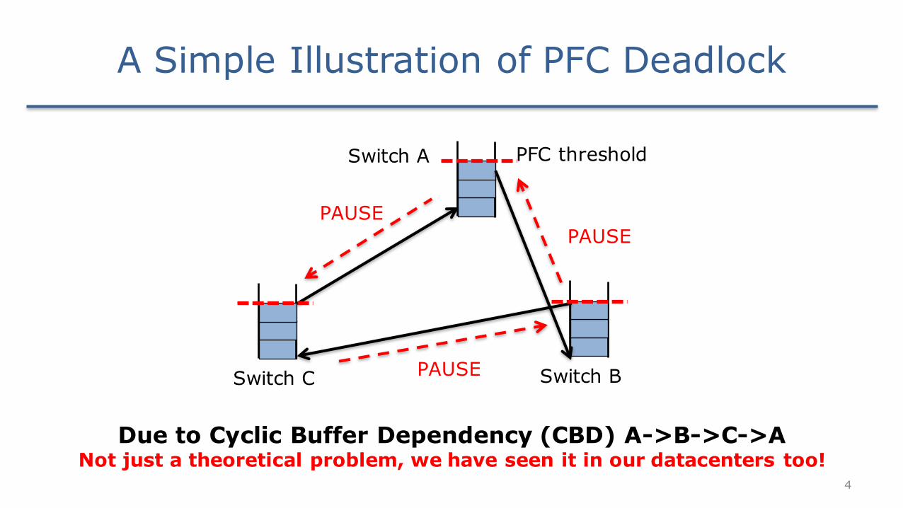
Due to Cyclic Buffer Dependency (CBD) A->B->C->ANot just a theoretical problem, we have seen it in our datacenters too!
PFC thresholdSwitch A
Switch BPAUSE
PAUSEPAUSE
Switch C
A Simple Illustration of PFC Deadlock
5
CBD in the Clos Network
L1 L2
T1 T2
L3 L4
T3 T4
S1 S2
6
L1 L2
T1 T2
L3 L4
T3 T4
S1 S2
flow 1 flow 2
consider two flows initially follow shortest UP-DOWN paths
CBD in the Clos Network
7
L1 L2
T1 T2
L3 L4
T3 T4
S1 S2
flow 1 flow 2
CBD in the Clos Network
due to link failures, both flows are locally rerouted to non-shortest paths
8
L1 L2
T1 T2
L3 L4
T3 T4
S1 S2
flow 1 flow 2
CBD: L2->S1->L3->S2->L2
L2
S1RX
L3
S2RX
RX RX
RX RX
buffer dependency graph
CBD in the Clos Network
these two DOWN-UP bounced flows create CBD
9
Real in Production Data Centers?
Packetreroutemeasurementsinmorethan20datacenters:
~100,000 DOWN-UP reroutes!
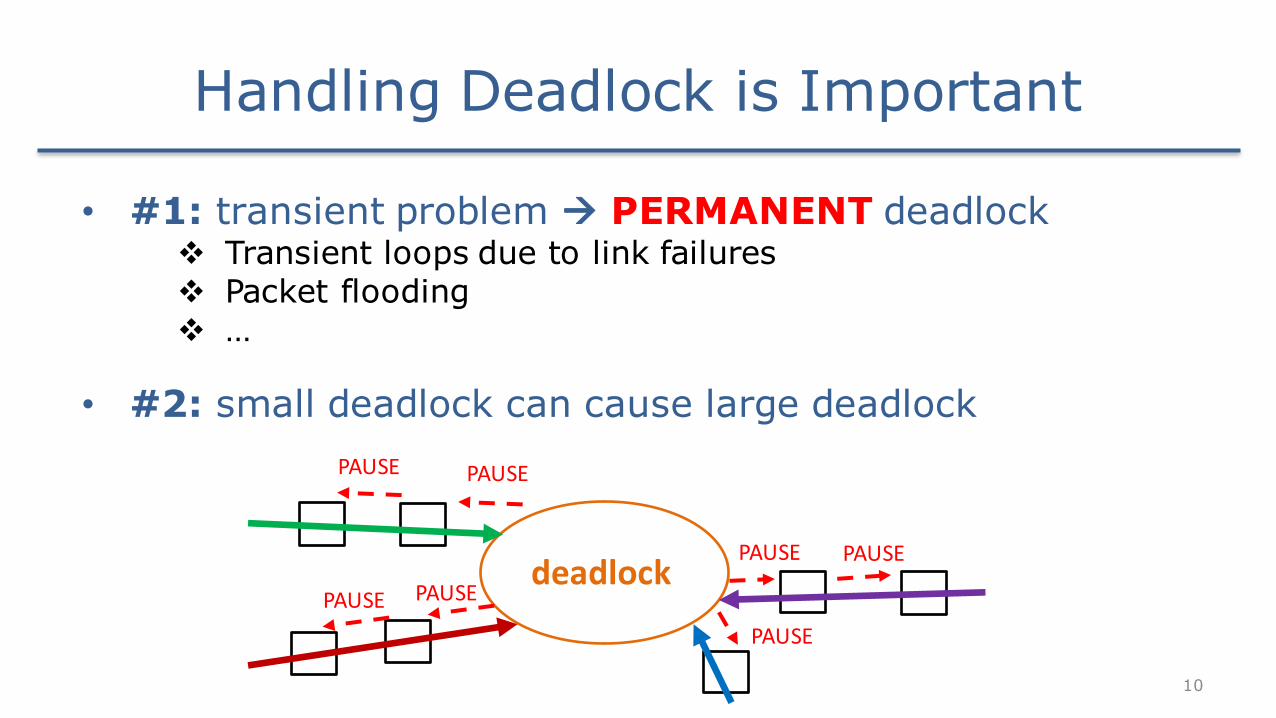
• #1: transient problem à PERMANENT deadlockv Transient loops due to link failuresv Packet floodingv …
• #2: small deadlock can cause large deadlock
deadlock
10
PAUSEPAUSE
PAUSE PAUSE
PAUSE
PAUSEPAUSE
Handling Deadlock is Important
Three Key Challenges
11
What are the challenges in designing a practical deadlock prevention solution?
Ø No change to existing routing protocols or hardwareØ Link failures & routing errors are unavoidable at scaleØ Switches support at most 8 limited lossless priorities
(and typically only two can be used)
• #1: deadlock-free routing protocolsv not supported by commodity switches (fail challenge #1)v not work with link failures or routing errors (fail challenge #2)
• #2: buffer management schemesv require a lot of lossless priorities (fail challenge #3)
12
The Existing Deadlock Prevention Solutions
Our answer: Tagger
TAGGER DESIGN
13
14
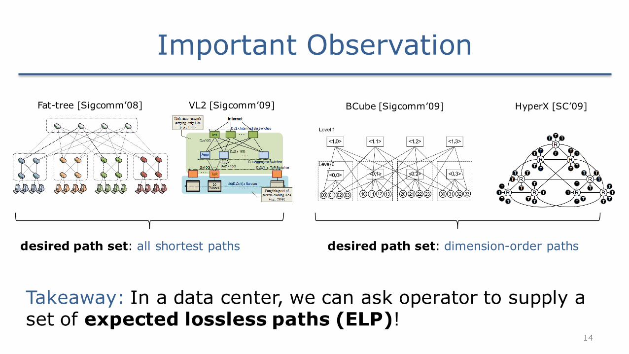
Important Observation
Fat-tree [Sigcomm’08] VL2 [Sigcomm’09]
desired path set: all shortest paths
BCube [Sigcomm’09]
desired path set: dimension-order paths
HyperX [SC’09]
Takeaway: In a data center, we can ask operator to supply a set of expected lossless paths (ELP)!
15
Basic Idea of Tagger
1. Ask operators to provide: v topology & expected lossless paths (ELP)
2. Packets carrying tags when in the network
3. Pre-install match-action rules at switches for tag manipulation and packet queueingv packets travel over ELP: lossless queues & CBD never formsv packets deviate ELP: lossy queue, thus PFC not triggered
16
L1 L2
T1 T2
L3 L4
T3 T4
S1 S2
flow 1 flow 2
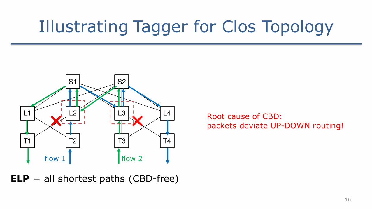
Illustrating Tagger for Clos Topology
ELP = all shortest paths (CBD-free)
Root cause of CBD: packets deviate UP-DOWN routing!
17
L1 L2
T1 T2
L3 L4
T3 T4
S1 S2
tag = NoBounce
• Under Tagger, packets carry tags when travelling in the network • Initially, tag value = NoBounce• At switches, Tagger pre-install match-action rules for tag manipulation
Tag InPort OutPort NewTag
NoBounce S1 S2 Bounced
… … … …
flow 1
match action
Illustrating Tagger for Clos Topology
match-action rules installed at switches
18
L1 L2
T1 T2
L3 L4
T3 T4
S1 S2
Packet received by switch L3
Tag InPort OutPort NewTag
NoBounce S1 S2 Bounced
… … … …
flow 1
match actiontag = NoBounce
Illustrating Tagger for Clos Topology
match-action rules installed at switches
19
L1 L2
T1 T2
L3 L4
T3 T4
S1 S2
tag = NoBounce
rewrite tag once DOWN-UP bounce detected
flow 1
match action
Tag InPort OutPort NewTag
NoBounce S1 S2 Bounced
… … … …
down-up bounce observed!
Bounced
Illustrating Tagger for Clos Topology
20
L1 L2
T1 T2
L3 L4
T3 T4
S1 S2 tag = Bounced
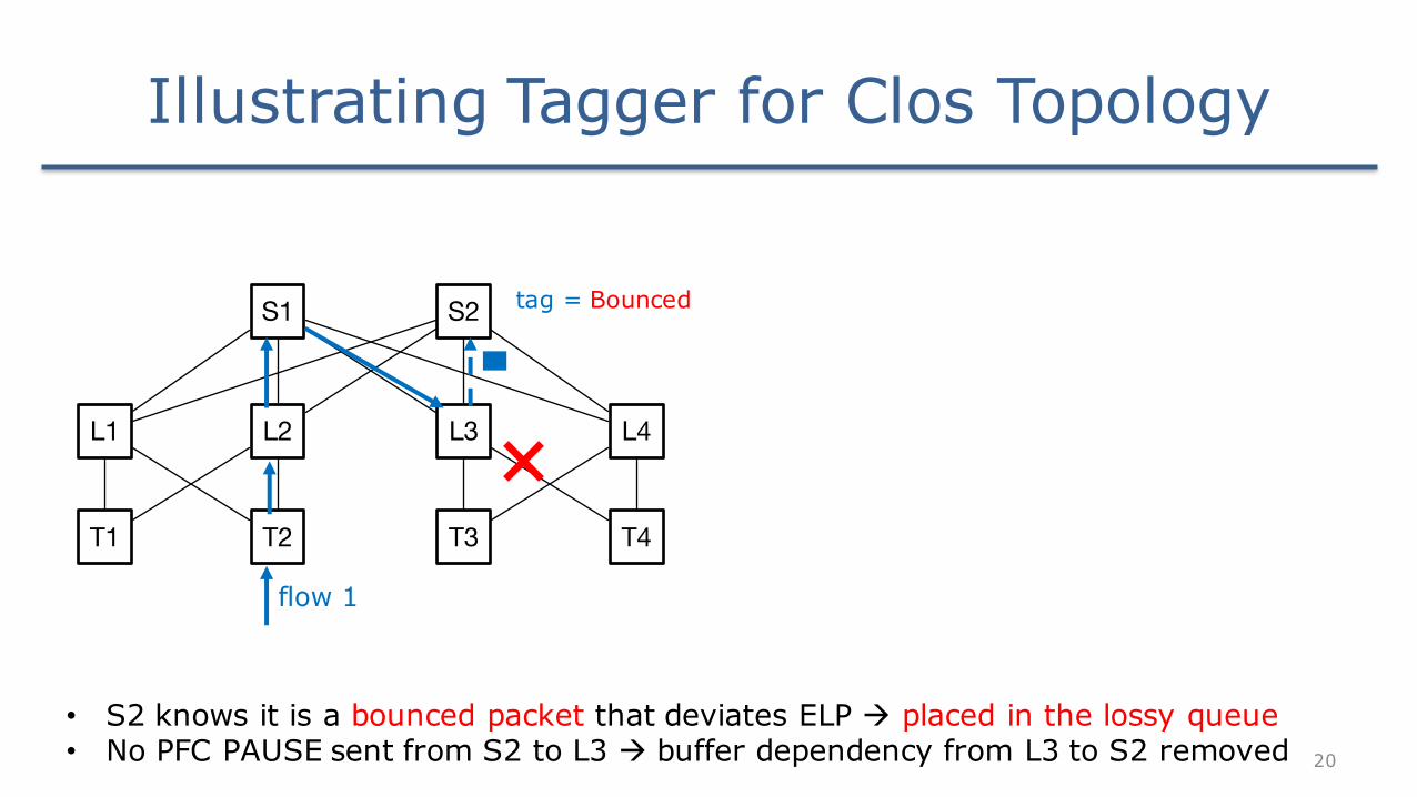
• S2 knows it is a bounced packet that deviates ELP à placed in the lossy queue• No PFC PAUSE sent from S2 to L3 à buffer dependency from L3 to S2 removed
flow 1
Illustrating Tagger for Clos Topology
21
L1 L2
T1 T2
L3 L4
T3 T4
S1 S2
flow 2
• Tagger will do the same for packets of flow 2• 2 buffer dependency edges are removed à CBD is eliminated
CBD: L2->S1->L3->S2->L2
L2
S1RX
L3
S2RX
RX RX
RX RX
buffer dependency graph
L2
S1RX
L3
S2RX
RX RX
RX RX
Illustrating Tagger for Clos Topology
22
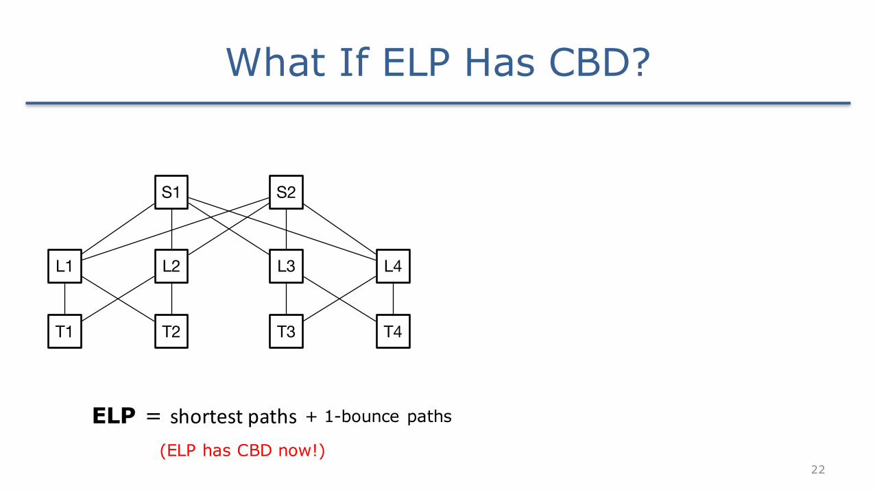
What If ELP Has CBD?
ELP = shortestpaths
L1 L2
T1 T2
L3 L4
T3 T4
S1 S2
+ 1-bounce paths
(ELP has CBD now!)
23
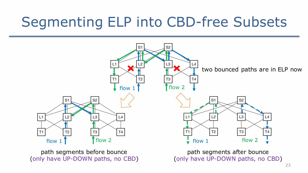
Segmenting ELP into CBD-free Subsets
L1 L2
T1 T2
L3 L4
T3 T4
S1 S2
flow 1 flow 2
L1 L2
T1 T2
L3 L4
T3 T4
S1 S2
flow 1 flow 2
L1 L2
T1 T2
L3 L4
T3 T4
S1 S2
flow 1 flow 2
path segments before bounce(only have UP-DOWN paths, no CBD)
two bounced paths are in ELP now
path segments after bounce(only have UP-DOWN paths, no CBD)
24
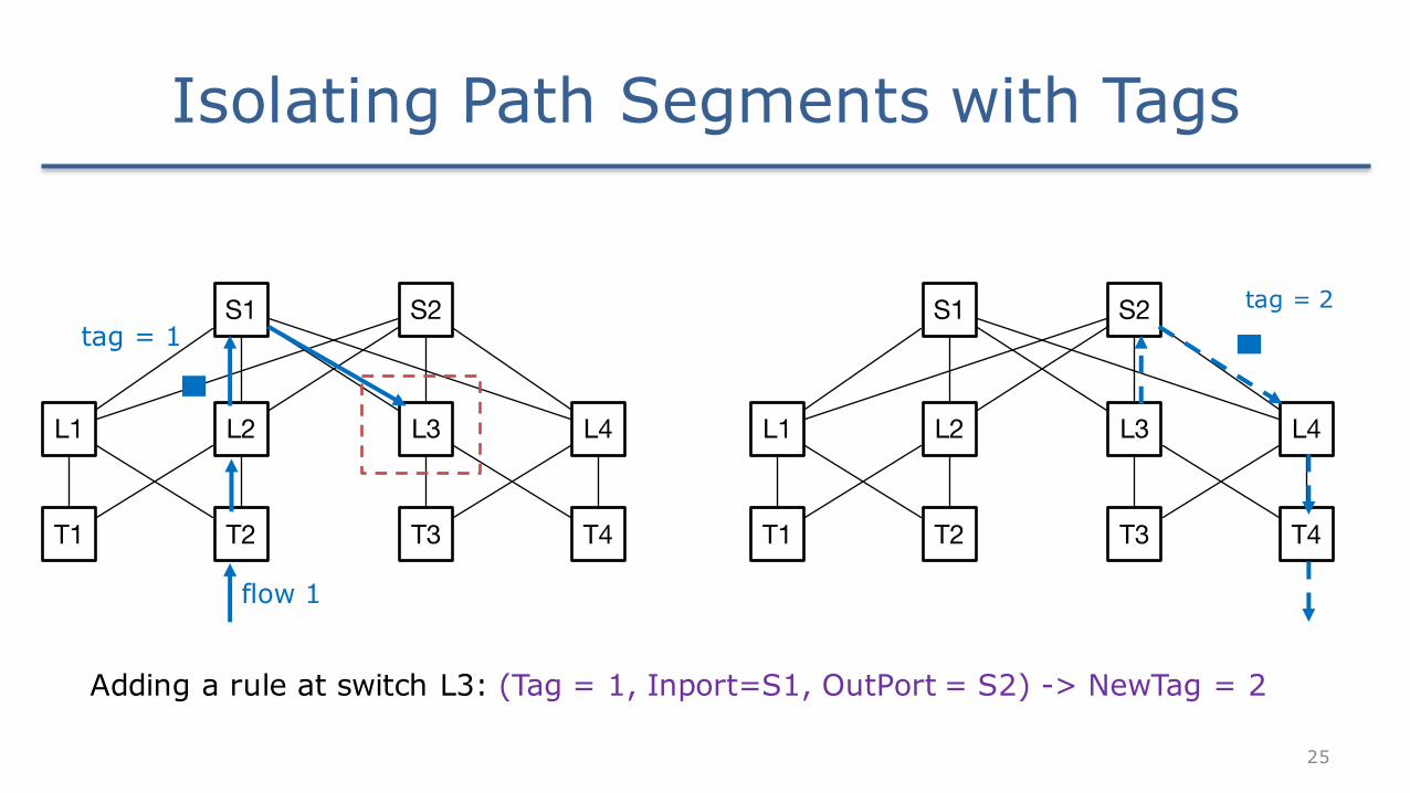
Isolating Path Segments with Tags
L1 L2
T1 T2
L3 L4
T3 T4
S1 S2
flow 1 flow 2
L1 L2
T1 T2
L3 L4
T3 T4
S1 S2
flow 1 flow 2
tag 1 à path segments before bounce tag 2 à path segments after bounce
25
L1 L2
T1 T2
L3 L4
T3 T4
S1 S2
flow 1
tag = 1
Isolating Path Segments with Tags
L1 L2
T1 T2
L3 L4
T3 T4
S1 S2 tag = 2
Adding a rule at switch L3: (Tag = 1, Inport=S1, OutPort = S2) -> NewTag = 2
26
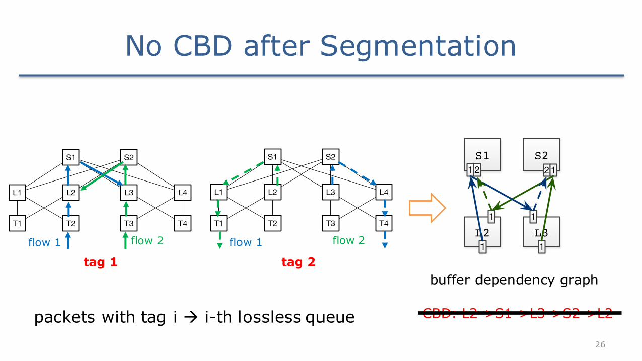
No CBD after Segmentation
CBD: L2->S1->L3->S2->L2
buffer dependency graph
L2
S112
1
1L3
S221
1
1
packets with tag i à i-th lossless queue
L1 L2
T1 T2
L3 L4
T3 T4
S1 S2
flow 1 flow 2
L1 L2
T1 T2
L3 L4
T3 T4
S1 S2
flow 1 flow 2
tag 2tag 1
27
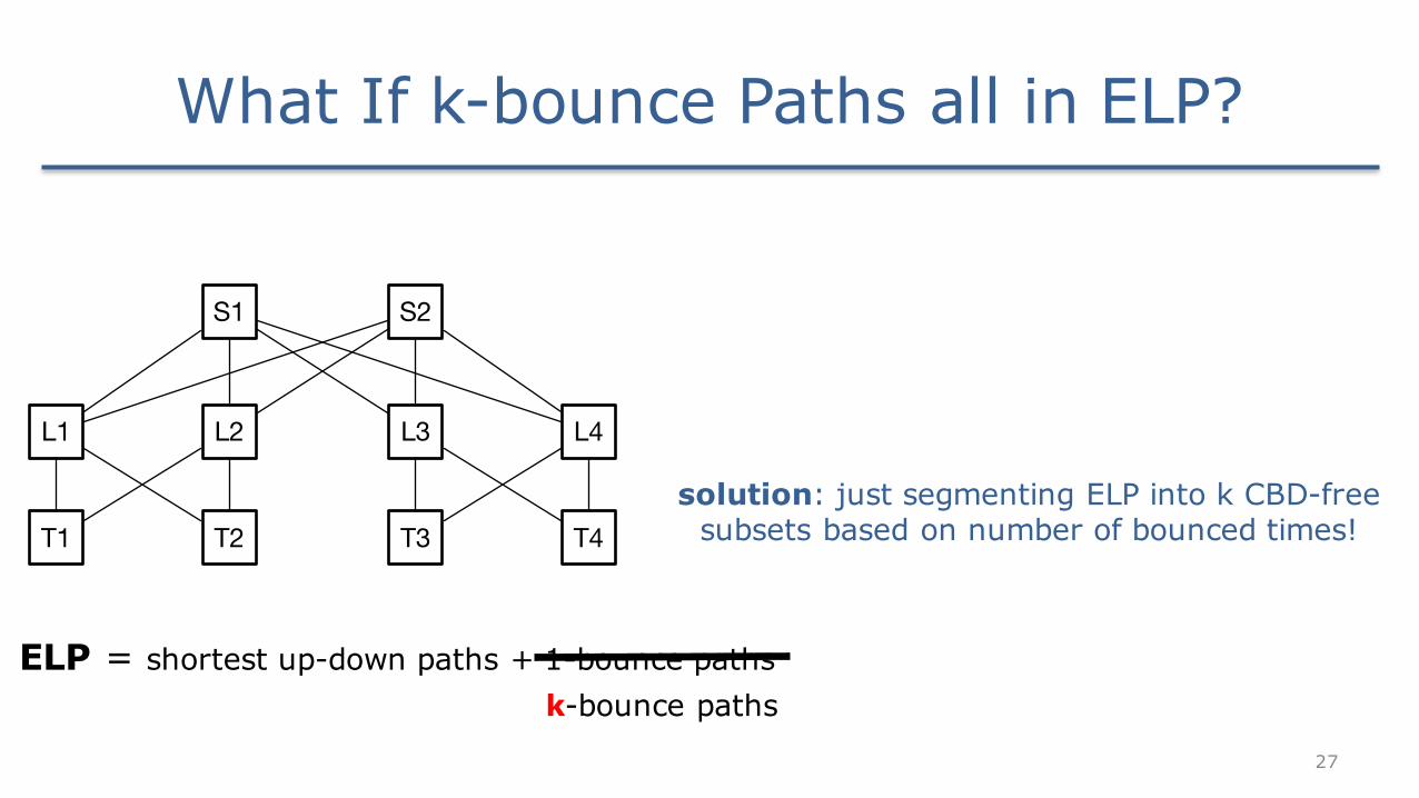
What If k-bounce Paths all in ELP?
ELP = shortest up-down paths + 1-bounce paths
L1 L2
T1 T2
L3 L4
T3 T4
S1 S2
k-bounce paths
solution: just segmenting ELP into k CBD-free subsets based on number of bounced times!
28
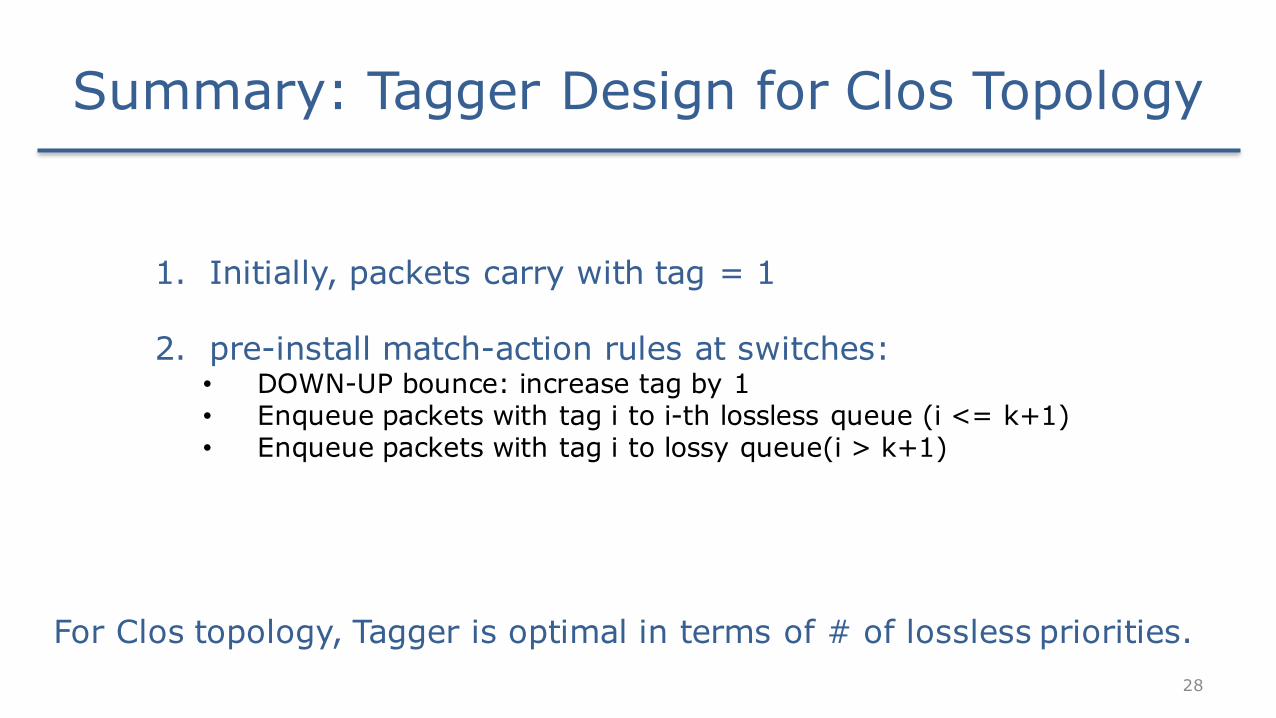
Summary: Tagger Design for Clos Topology
1. Initially, packets carry with tag = 1
2. pre-install match-action rules at switches:• DOWN-UP bounce: increase tag by 1 • Enqueue packets with tag i to i-th lossless queue (i <= k+1)• Enqueue packets with tag i to lossy queue(i > k+1)
For Clos topology, Tagger is optimal in terms of # of lossless priorities.
29
How to Implement Tagger?
• DSCP field in the IP header as the tag carried in the packets
• build 3-step match-action pipeline with basic ACL rules available in commodity switches
30
Tagger Meets All the Three Challenges
1. Work with existing routing protocols & hardware


![[doi 10.1109_icept.2009.5270785] Rong, Yibo; Cai, Jian; Wang, Shuidi; Jia, Songliang -- [IEEE High Density Packaging (ICEPT-HDP) - Beijing, China (2009.08.10-2009.08.13)] 2009 International](https://static.documents.pub/doc/80x56/55cf8def550346703b8cdd92/doi-101109icept20095270785-rong-yibo-cai-jian-wang-shuidi-jia.jpg)


