AEROSPACE REPORT NO. TR-2020-01914 Tailoring of SMC-S-010 (2013), Technical Requirements for Electronic Parts, Materials, and Processes Used in Space Vehicles August 14, 2020 Brandon N. Davis Parts, Materials and Processes Department Electronics Engineering Subdivision Prepared for: Space and Missile Systems Center United States Space Force 483 N. Aviation Blvd. El Segundo, CA 90245-2808 Contract No. FA8802-19-C-0001 Authorized by: Space Systems Group Distribution Statement A: Approved for public release; distribution unlimited.
Transcript
AEROSPACE REPORT NO. TR-2020-01914
Tailoring of SMC-S-010 (2013), Technical Requirements for Electronic Parts, Materials, and Processes Used in Space Vehicles
August 14, 2020
Brandon N. Davis Parts, Materials and Processes Department Electronics Engineering Subdivision
Prepared for: Space and Missile Systems Center United States Space Force 483 N. Aviation Blvd. El Segundo, CA 90245-2808
Contract No. FA8802-19-C-0001
Authorized by: Space Systems Group
Distribution Statement A: Approved for public release; distribution unlimited.
This report was submitted by The Aerospace Corporation, El Segundo, CA 90245-4691, under Contract No. FA8802-14-C-0001 with the Space and Missile Systems Center, 483 N. Aviation Blvd., El Segundo, CA 90245. It was reviewed and approved for The Aerospace Corporation by Anthony T. Salvaggio, Jr., Principal Director. Franco R. Macchia was the project officer for the SMC Atlas Corps Directorate of Engineering. This report has been reviewed by the Public Affairs Office (PAS) and is releasable to the National Technical Information Service (NTIS). At NTIS, it will be available to the general public, including foreign nationals. This technical report has been reviewed and is approved for publication. Publication of this report does not constitute Air Force approval of the report’s findings or conclusions. It is published only for the exchange and stimulation of ideas until adopted or otherwise implemented by the government.
Thomas T. Pham, NH-03, DAF
All trademarks, service marks, and trade names are the property of their respective owners.
REPORT DOCUMENTATION PAGE Form Approved OMB No. 0704-0188
Public reporting burden for this collection of information is estimated to average 1 hour per response, including the time for reviewing instructions, searching existing data sources, gathering and maintaining the data needed, and completing and reviewing this collection of information. Send comments regarding this burden, estimate or any other aspect of this collection of information, including suggestions for reducing this burden to Department of Defense, Washington Headquarters Services, Directorate for Information Operations and Reports (0704-0188), 1215 Jefferson Davis Highway, Suite 1204, Arlington, VA 22202-4302. Respondents should be aware that notwithstanding any other provision of law, no person shall be subject to any penalty for failing to comply with a collection of information if it does not display a currently valid OMB control number. PLEASE DO NOT RETURN YOUR FORM TO THE ABOVE ADDRESS. 1. REPORT DATE (DD-MM-YYYY)
14-08-2020 2. REPORT TYPE
3. DATES COVERED (From - To)
4. TITLE AND SUBTITLE
5a. CONTRACT NUMBER FA8802-19-C-0001
Tailoring of SMC-S-010 (2013), Technical Requirements for Electronic Parts, Materials, and Processes Used in Space Vehicles
5b. GRANT NUMBER
5c. PROGRAM ELEMENT NUMBER
6. AUTHOR(S)
5d. PROJECT NUMBER
Brandon N. Davis
5e. TASK NUMBER
5f. WORK UNIT NUMBER
7. PERFORMING ORGANIZATION NAME(S) AND ADDRESS(ES)
8. PERFORMING ORGANIZATION REPORT NUMBER
The Aerospace Corporation 2310 E. El Segundo Blvd. El Segundo, CA 90245-4691
TR-2020-01914
9. SPONSORING/MONITORING AGENCY NAME(S) AND ADDRESS(ES) 10. SPONSOR/MONITOR’S ACRONYM(S)
SMC
United States Space Force 483 N. Aviation Blvd. 11. SPONSOR/MONITOR’S REPORT
NUMBER(S) El Segundo, CA 90245
12. DISTRIBUTION/AVAILABILITY STATEMENT Approved for public release; distribution unlimited. 13. SUPPLEMENTARY NOTES
14. ABSTRACT This document tailors USAF Space and Missile Systems Center (SMC) standard number SMC-S-010 (2013), entitled “Technical Requirements for Electronic Parts, Materials, and Processes Used in Space Vehicles”, to provide an effective space vehicle (SV) program technical baseline for parts, materials, and processes (PM&P) and national security space mission success. These documents, together, are intended for use in acquisition and study contracts for SVs. This tailoring is based on a joint Aerospace-SMC assessment of test requirements currently on, or required for near-term future, SMC contracts. The goal was to streamline those requirements that are either commonly tailored or can be re-stated to facilitate more effective implementation. 15. SUBJECT TERMS Parts, materials, and processes; PM&P; Standard; Tailoring 16. SECURITY CLASSIFICATION OF:
17. LIMITATION OF ABSTRACT
18. NUMBER OF PAGES
19a. NAME OF RESPONSIBLE PERSON
Brandon N. Davis a. REPORT UNCLASSIFIED
b. ABSTRACT
UNCLASSIFIED
c. THIS PAGE
UNCLASSIFIED
17 19b. TELEPHONE NUMBER (include area code)
(310) 336-2836
Standard Form 298 (Rev. 8-98) Prescribed by ANSI Std. 239.18
iv
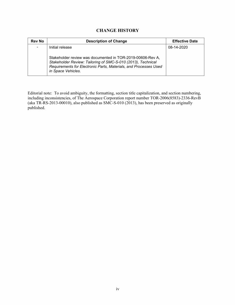
CHANGE HISTORY
Rev No Description of Change Effective Date - Initial release
Stakeholder review was documented in TOR-2019-00606-Rev A, Stakeholder Review: Tailoring of SMC-S-010 (2013), Technical Requirements for Electronic Parts, Materials, and Processes Used in Space Vehicles.
08-14-2020
Editorial note: To avoid ambiguity, the formatting, section title capitalization, and section numbering, including inconsistencies, of The Aerospace Corporation report number TOR-2006(8583)-2336-RevB (aka TR-RS-2013-00010), also published as SMC-S-010 (2013), has been preserved as originally published.
APPENDIX B RESCREENING/QUALITY CONFORMANCE INSPECTION REQUIREMENTS ................................................................................................................ 17
APPENDIX C ALTERNATE QCI TEST/SAMPLING PLAN ...................................................... 17 APPENDIX D NOTES .................................................................................................................... 17
1
0BForeword ADD THE FOLLOWING: This document is a tailoring of USAF Space and Missile Systems Center (SMC) standard number SMC-S-010 (2013), originally published as The Aerospace Corporation report number TOR-2006(8583)-5236 Revision A, entitled Technical Requirements for Electronic Parts, Materials, and Processes Used in Space Vehicles, to provide an effective space vehicle (SV) program technical baseline for parts, materials, and processes (PM&P) and national security space mission success. These documents, together, are intended for use in acquisition and study contracts for SVs. The SMC standard tailored by this document (hereafter referred to as the “tailored SMC standard”) is intended to be used as a compliance document to specify electronic PM&P requirements for SVs. Tailoring Intent This tailoring is based on a joint Aerospace-SMC assessment of PM&P requirements currently on, or required for near-term future, SMC contracts. The goal was to streamline those requirements that are either commonly tailored or can be re-stated to facilitate more effective implementation. Formatting of this Tailoring Document The outline organization in this tailoring document is consistent with SMC-S-008 (2013), originally published as The Aerospace Corporation report number TOR-2006(8583)-5236 Revision B (aka TR-RS-2013-00010). To avoid ambiguity, the formatting, section title capitalization, and section numbering, including inconsistencies, has been preserved as originally published. Tailoring Definition Tailoring is a process by which individual requirements from specifications, standards, or related documents are evaluated and applied to a specific program by deletion, modification, or addition of requirements. Tailoring of requirements must be undertaken with consultation and approval of the procuring authority and the Aerospace PM&P subject matter expert to align the standard with the acquisition authority’s requirements and the mission needs. The diversity of missions, buses, payloads, environments, and unique approaches of contractors makes tailoring of standard requirements mandatory. This tailored SMC Standard establishes a baseline for requirements, which in turn may be tailored or revised with rationale for specific project needs upon approval by the procuring authority.
2
Summary of Tailoring The following is a comprehensive list of the changes that this document imposes on SMC-S-010 (2013).
Section Title Change Summary n/a Foreword Added background for this tailoring. 4.1.2 Margin of Safety Simplified and clarified requirement for
derating to factor of safety of mechanical parts and materials.
4.4.4 Destructive Physical Analysis (DPA) Specifies sample size as 3 pieces per lot unless otherwise specified by PMPCB.
Section 100 3.1b
Rigid Printed Wiring Boards Tailored text is consistent with current industry standard practices.
In Process Controls The alternate method in item a. has been shown to be a reliable method of ensuring copper plating properties and is consistent with current industry standard practices. Removed inner layer inspection of rigid boards to be consistent with current industry practices.
Section 100 5 Registered (Reliability Suspect) Addresses concerns for using lead-free solder.
Section 110 3.2j
All Flex and Rigid-Flex Removed redundant in-process cleanliness test.
Section 110 3.2n
All Flex and Rigid-Flex Stacking of flex PWBs when drilling is not standard practice, so this requirement is not necessary.
Section 110 3.3d
Multiple layer flex and rigid-flex boards with plated-through-holes
Tailored text to be consistent with current industry standard practices.
Section 110 4.1
PWBs In-process Control Allows alternative to mechanical testing. Removed inner layer inspection of flex boards to be consistent with current industry practices.
Section 110 5
PWB: Registered (Reliability Suspect) PMP Tailored text to be consistent with current standard practices and address concern of lead-free plating.
Section 120 3.1 b
RF (microwave) PWBs; PWBs Etch Back Tailored text to be consistent with current industry standard practices.
Section 120 3.1 p
RF (Microwave) PWBs; PWBs; Hot Air Leveling
Removed redundant in-process cleanliness test.
Section 120 4.1
PWBs; In-process Controls Tailored text to be consistent with current industry standard practices.
Section 120 5
PWBs; Registered (Reliability Suspect) Tailored text to be consistent with current standard practices and address concern of lead-free plating.
3
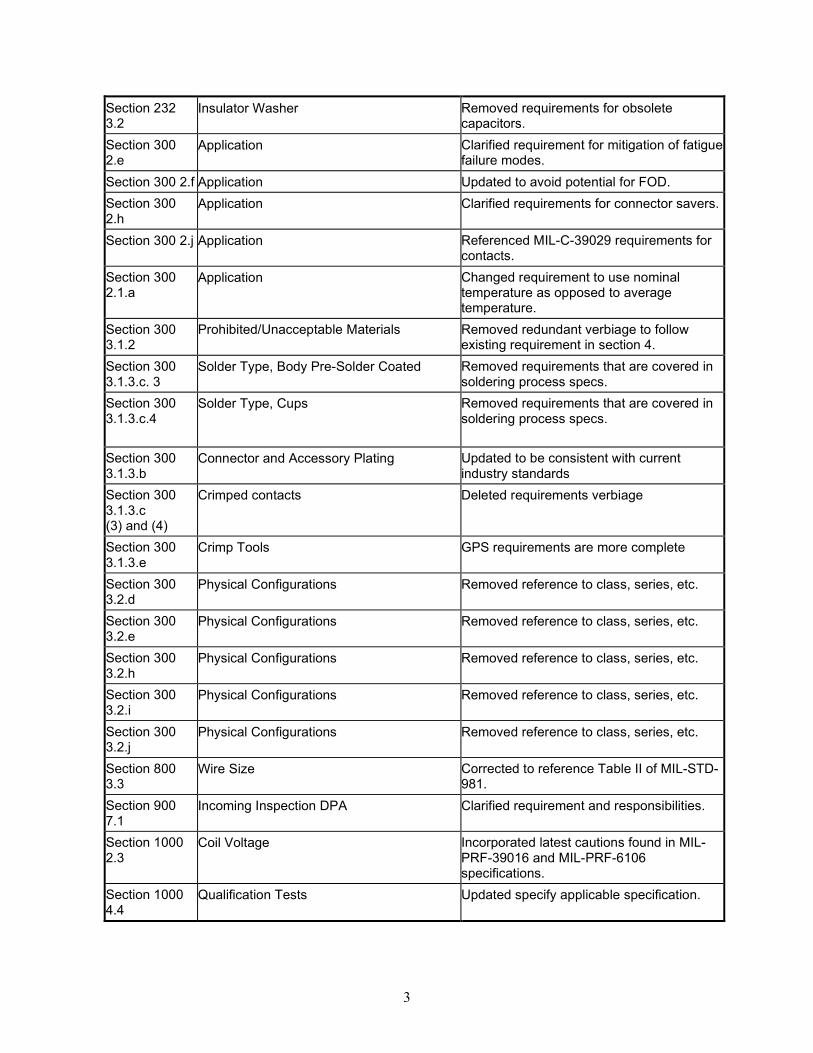
Section 232 3.2
Insulator Washer Removed requirements for obsolete capacitors.
Section 300 2.e
Application Clarified requirement for mitigation of fatigue failure modes.
Section 300 2.f Application Updated to avoid potential for FOD. Section 300 2.h
Application Clarified requirements for connector savers.
Section 300 2.j Application Referenced MIL-C-39029 requirements for contacts.
Section 300 2.1.a
Application Changed requirement to use nominal temperature as opposed to average temperature.
Section 300 3.1.2
Prohibited/Unacceptable Materials
Removed redundant verbiage to follow existing requirement in section 4.
Section 300 3.1.3.c. 3
Solder Type, Body Pre-Solder Coated Removed requirements that are covered in soldering process specs.
Section 300 3.1.3.c.4
Solder Type, Cups Removed requirements that are covered in soldering process specs.
Section 300 3.1.3.b
Connector and Accessory Plating Updated to be consistent with current industry standards
Section 300 3.1.3.c (3) and (4)
Crimped contacts Deleted requirements verbiage
Section 300 3.1.3.e
Crimp Tools GPS requirements are more complete
Section 300 3.2.d
Physical Configurations Removed reference to class, series, etc.
Section 300 3.2.e
Physical Configurations Removed reference to class, series, etc.
Section 300 3.2.h
Physical Configurations Removed reference to class, series, etc.
Section 300 3.2.i
Physical Configurations Removed reference to class, series, etc.
Section 300 3.2.j
Physical Configurations Removed reference to class, series, etc.
Section 800 3.3
Wire Size Corrected to reference Table II of MIL-STD-981.
Section 900 7.1
Incoming Inspection DPA Clarified requirement and responsibilities.
Section 1000 2.3
Coil Voltage Incorporated latest cautions found in MIL-PRF-39016 and MIL-PRF-6106 specifications.
Stress Corrosion Cracking Modified to allow the use of aluminum alloys if they are under 75% of their stress corrosion threshold.
Section 3500 2.1
Printed Circuit Assembly; Soldering
Removed requirements that exist in J-STD-001 and specified usage of space addendum.
Appendix A A.7
Radiation Hardness Assurance Requirements For Hybrid Microcircuits and Multichip Modules
Removed requirements that exist in A1 – A6.
Appendix B RESCREENING/QUALITY CONFORMANCE INSPECTION REQUIREMENTS
Clarified requirements for using life test samples.
Appendix C ALTERNATE QCI TEST/SAMPLING PLAN Corrected referenced paragraph numbers.
5
1. 1BScope There are no changes to this section. Use SMC-S-010 (2013) verbatim. 2. 2BReference Documents There are no changes to this section. Use SMC-S-010 (2013) verbatim. 3. 3BDefinitions There are no changes to this section. Use SMC-S-010 (2013) verbatim. 4. 4BGeneral Requirements 4.1 7BApplication Requirements 92B4.1.2 Change to: Margin of Safety CHANGE TO: Mechanical parts and materials shall meet the factor, or margin of safety as derived or specified in the application component, or structural assembly specification. Strength margins shall be based on mechanical property data from MIL-HDBK-5J (CANCELED) where applicable and shall delimit susceptibility to mechanical failure modes such as bending, deformation, fracture, rupture, excessive deflection, and fatigue. Functional margins shall be calculated based on the recommendation of MIL-A-83577B (CANCELED) wherever possible.
4.2 8BPMP Requirements There are no changes to this section. Use SMC-S-010 (2013) verbatim.
4.3 9BPMP Design, Construction, and Procurement There are no changes to this section. Use SMC-S-010 (2013) verbatim.
4.4 10BPart Quality Assurance Provisions 93B4.4.4 Destructive Physical Analysis (DPA). CHANGE TO: Destructive Physical Analysis shall be performed in accordance with MIL-STD-1580 and the detailed sections herein. DPA sample size shall be 3 pieces per lot unless otherwise approved by PMPCB.
4.5 11BMaterial Quality Assurance Provisions There are no changes to this section. Use SMC-S-010 (2013) verbatim.
4.6 12BPackaging There are no changes to this section. Use SMC-S-010 (2013) verbatim.
4.7 13BElectrostatic-Sensitive Items There are no changes to this section. Use SMC-S-010 (2013) verbatim.
6
4.8 14BData and Record Retention There are no changes to this section. Use SMC-S-010 (2013) verbatim. 5. 5BDetailed Requirements REVISE AS FOLLOWS. Otherwise use SMC-S-010 (2013) verbatim.
b. CHANGE TO: Etchback or equivalent processes shall be used to ensure resin smear is completely removed from the holes of multilayer boards prior to plating. When etchback is used, the limits shall be 0.0002 inch minimum and 0.002 inch maximum. p. Hot Air Leveling CHANGE TO: PWBs shall only be hot air leveled once. The solder coating shall be homogeneous and completely cover the conductors with no pitting, no pinholes, or non-wet areas. Sidewalls of conductors need not be solder-coated. Touch-up is permitted but is limited to no more than 5 percent of lands or pads.
4.1 In Process Controls
a. Elongation and Tensile Strength CHANGE TO: Elongation and tensile strength of as-plated copper shall be tested at least once a month. An alternative method is to statistically monitor the copper plating bath to maintain the level of bath organic compound composition. b. Inner Layer Inspection. DELETE
5. REGISTERED (RELIABILITY SUSPECT)
CHANGE TO: Space systems are particularly vulnerable because of the severe environment and the impossibility of repairing fielded equipment. Lead-free tin platings/coatings and solders represent a significant reliability risk in space applications and shall not be used except as noted in Section 4.0.
16BSection 110 FLEX AND RIGID-FLEX PRINTED WIRING BOARDS 3.2 All Flex and Rigid–Flex
j. Hot Air Leveling
CHANGE TO: The PWBs shall only be hot air leveled once. The solder coating shall be homogenous and completely cover the conductors with no pitting, no pinholes, or non-wet areas. Sidewalls of conductors need not be solder-coated. Touch-up is permitted but is limited to no more than 5% of lands of pads.
7
n. Stacking of Panels When Drilling Plated Through Holes. DELETE
3.3 Multiple Layer Flex and Rigid-Flex Boards with Plated-Through-Holes
d. Etchback
CHANGE TO: Etchback or equivalent processes shall be used to ensure complete resin smear removal from the holes of multilayer boards prior to plating. When etchback is used, the limits shall between 0.0002 inch minimum and 0.002 inch maximum.
4.1 In Process Controls
a. CHANGE TO: Elongation and tensile strength of as-plated copper shall be tested at least once a month. An alternate method is to statistically monitor copper plating bath to maintain the level of bath organic compound composition.
b. Inner layer Inspection. DELETE
5. REGISTERED (RELIABILITY SUSPECT) PMP
b. CHANGE TO: Microvias.
c. CHANGE TO: Vias plated blind (i.e., not made by sequential lamination)
d. CHANGE TO: Space systems are particularly vulnerable because of the severe environment and the impossibility of repairing fielded equipment. Lead-free tin platings/coatings and solders represent a significant reliability risk in space applications and shall not be used except as noted in Section 4.
b. CHANGE TO: Etchback shall be used to ensure resin smear is completely removed from the holes of the multilayer boards prior to plating. When etchback is used, the limits shall be between 0.0002 inch minimum and 0.002 inch maximum for non-PTFE material. For PTFE material, the etchback shall be between non-negative etchback and positive etchback of 0.002 inch. p. CHANGE TO: Hot Air Leveling. PWB shall only be hot air leveled once. The solder coating shall be homogenous and completely cover the conductors with no pitting, no pinholes, or non-wet areas. Sidewalls of conductors need not be solder-coated. Touch-up shall be limited to no more than 5% of lands of pads
4.1 In-Process Controls
a. CHANGE TO: Elongation and tensile strength of as-plated copper shall be tested at least once a month. An alternate method is to statistically monitor the copper plating bath to maintain the level of organic compound composition within defined limits that shall directly correlate to assure requirements are met.
8
b. CHANGE TO: Inner layer Inspection. Prior to lamination, all inner layers shall be 100% inspected for continuity and shorts, and visually inspected for correct line width and spacing.
5. REGISTERED (RELIABILITY SUSPECT) PMP
c. CHANGE TO: Space Systems are particularly vulnerable because of the severe environment and the impossibility of repairing fielded equipment. Lead-free tin platings/coatings and solders represent a significant reliability risk in space applications and shall not be used except as noted in Section 4.
18BSECTION 200 CAPACITORS, GENERAL There are no changes to this section. Use SMC-S-010 (2013) verbatim.
19BSECTION 210 MULTILAYER CERAMIC CAPACITORS There are no changes to this section. Use SMC-S-010 (2013) verbatim.
20BSECTION 216 STACKED CERAMIC CAPACITORS (SM) There are no changes to this section. Use SMC-S-010 (2013) verbatim.
21BSECTION 217 CERAMIC CAPACITORS ARRAYS FOR FILTER CONNECTORS There are no changes to this section. Use SMC-S-010 (2013) verbatim.
22BSECTION 230 METALLIZED FILM CAPACITORS (CRH) There are no changes to this section. Use SMC-S-010 (2013) verbatim.
23BSECTION 232 METALLIZED FILM CAPACITORS (CHS) (MIL-PRF-87217A) (OBSOLETE FOR NEW DESIGNS) 3.2 Insulator Washer
CHANGE TO: An insulator washer shall be added between the babbit end metallization and glass-to--metal end seal on both ends. The babbit material contains a high percentage of tin, and the process of applying the babbit creates a surface morphology that is susceptible to whisker formation. Tin whiskers can short circuit the end metallization and end seal.
24BSECTION 240 GLASS DIELECTRIC CAPACITORS (CYR) (MIL-PRF-23269) (OBSOLETE FOR NEW DESIGNS) There are no changes to this section. Use SMC-S-010 (2013) verbatim.
9
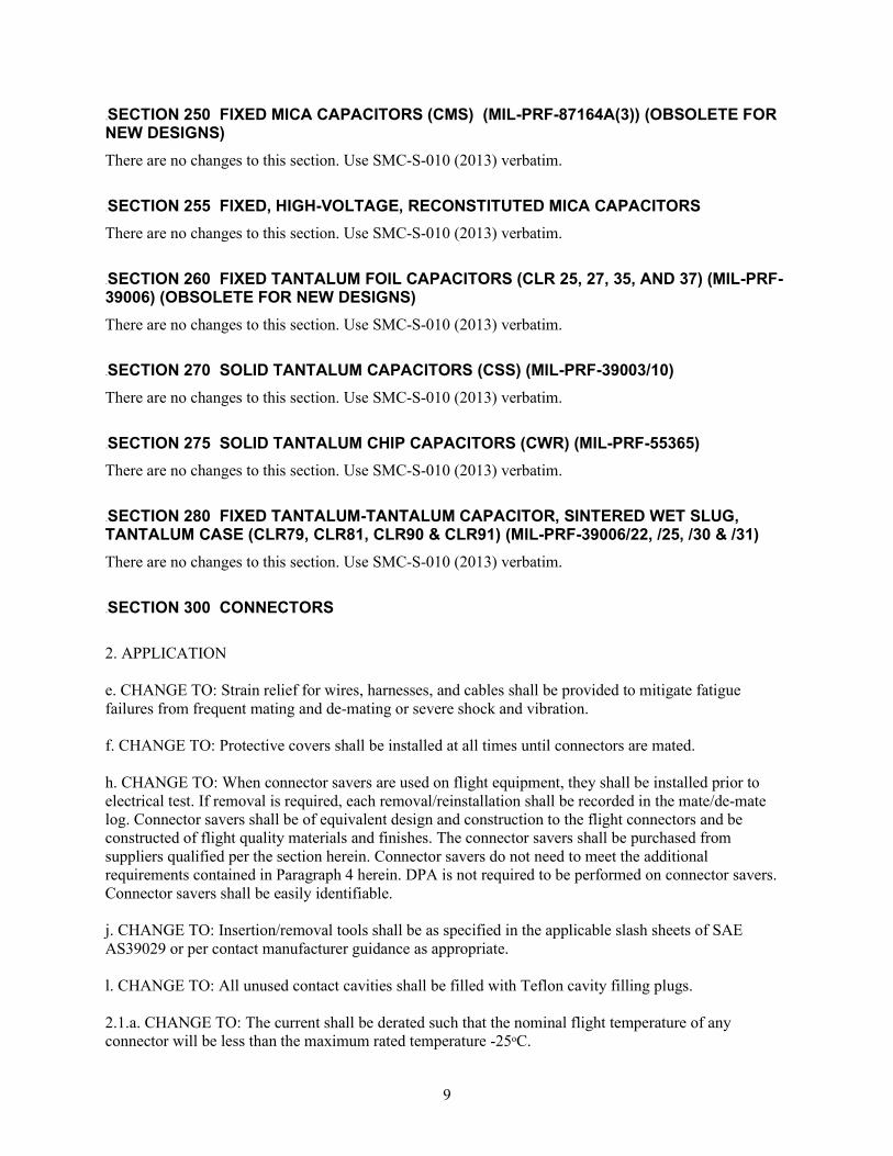
25BSECTION 250 FIXED MICA CAPACITORS (CMS) (MIL-PRF-87164A(3)) (OBSOLETE FOR NEW DESIGNS) There are no changes to this section. Use SMC-S-010 (2013) verbatim.
26BSECTION 255 FIXED, HIGH-VOLTAGE, RECONSTITUTED MICA CAPACITORS There are no changes to this section. Use SMC-S-010 (2013) verbatim.
27BSECTION 260 FIXED TANTALUM FOIL CAPACITORS (CLR 25, 27, 35, AND 37) (MIL-PRF-39006) (OBSOLETE FOR NEW DESIGNS) There are no changes to this section. Use SMC-S-010 (2013) verbatim.
28BSECTION 270 SOLID TANTALUM CAPACITORS (CSS) (MIL-PRF-39003/10) There are no changes to this section. Use SMC-S-010 (2013) verbatim.
29BSECTION 275 SOLID TANTALUM CHIP CAPACITORS (CWR) (MIL-PRF-55365) There are no changes to this section. Use SMC-S-010 (2013) verbatim.
30BSECTION 280 FIXED TANTALUM-TANTALUM CAPACITOR, SINTERED WET SLUG, TANTALUM CASE (CLR79, CLR81, CLR90 & CLR91) (MIL-PRF-39006/22, /25, /30 & /31) There are no changes to this section. Use SMC-S-010 (2013) verbatim.
31BSECTION 300 CONNECTORS 2. APPLICATION e. CHANGE TO: Strain relief for wires, harnesses, and cables shall be provided to mitigate fatigue failures from frequent mating and de-mating or severe shock and vibration. f. CHANGE TO: Protective covers shall be installed at all times until connectors are mated. h. CHANGE TO: When connector savers are used on flight equipment, they shall be installed prior to electrical test. If removal is required, each removal/reinstallation shall be recorded in the mate/de-mate log. Connector savers shall be of equivalent design and construction to the flight connectors and be constructed of flight quality materials and finishes. The connector savers shall be purchased from suppliers qualified per the section herein. Connector savers do not need to meet the additional requirements contained in Paragraph 4 herein. DPA is not required to be performed on connector savers. Connector savers shall be easily identifiable. j. CHANGE TO: Insertion/removal tools shall be as specified in the applicable slash sheets of SAE AS39029 or per contact manufacturer guidance as appropriate. l. CHANGE TO: All unused contact cavities shall be filled with Teflon cavity filling plugs. 2.1.a. CHANGE TO: The current shall be derated such that the nominal flight temperature of any connector will be less than the maximum rated temperature -25ᵒC.
10
3. DESIGN AND CONSTRUCTION 3.1.3 b Connector and Accessory Plating (2) CHANGE TO: Machined aluminum shells—gold plated per MIL-DTL-45204, Type II, Grade C, Class 1 (0.000050 inch minimum) over a nickel underplate of 0.000100 inch minimum in accordance with ASTM B7333, Class 1, shall have a double zincate coating preceding the nickel plating. Aluminum alloy parts—electroless nickel per the associated military connecter specification shall have a double zincate coating preceding the nickel plating. 3.1.3 c Contact Plating (3) DELETE and designate “reserved” (4) DELETE and designate “reserved” 3.1.3 d Crimped Contacts. CHANGE TO: Multi contact non-hermetic connectors should use crimp rear release contacts. Solder contacts shall be limited to potted and hermetic applications. 3.1.3 e Crimp Tools. CHANGE TO: As a minimum, crimping tools shall comply with the Class II requirements of MIL-C-22520 (CANCELED) and be tested and inspected for condition and performance before each use. 3.2 Physical Configurations. d. CHANGE TO: MIL-DTL-26482 (Circular, Miniature, Quick Disconnect, Environment Resisting) e. CHANGE TO: MIL-DTL-38999 (Circular, High Density) h. CHANGE TO: MIL-DTL-83723, Series III (Circular, Environment Resisting) i. CHANGE TO: MIL-DTL-83733 (Rack and panel, Rectangular) j. CHANGE TO: MIL-DTL-83513 (Rectangular Microminiature) 4.3 Group B Tests CHANGE TO: Group B tests shall be in accordance with the requirements of the applicable military specification 4.5 Incoming Inspections. CHANGE TO: All metal surfaces shall be verified for the absence of prohibited materials (e.g., pure tin, zinc, or cadmium). Unless otherwise directed by the PMPCB, incoming inspection DPA in accordance with MIL-STD-1580 is only required for filter-pin connectors, connectors supplied with flying leads(e.g. MIL-PRF-83513/3,4,8,9), non-traditional styles (e.g., brush connectors, backplane connectors, nano connectors, mixed-contact type connectors or, others with <25-mil contact spacing), or connectors provided by commercial suppliers (i.e., manufacturers not Defense Logistics Agency approved). Incoming inspection DPA is not required for connectors that are Space Quality Baseline, NASA standard, QPL listed (except for those types identified above), or non-QPL listed parts (expect for those types identified above) produced at a QPL facility. Nor is DPA required for the connector contacts (except for filter pins). 6. PROHIBITED PMP There are no changes to this section. Use SMC-S-010 (2013) verbatim.
11
32BSECTION 310 CONNECTORS, FILTERED There are no changes to this section. Use SMC-S-010 (2013) verbatim.
33BSECTION 400 QUARTZ CRYSTALS (MIL-C-49468, CANCELED) There are no changes to this section. Use SMC-S-010 (2013) verbatim.
34BSECTION 410 CRYSTAL OSCILLATORS & CRYSTAL FILTERS There are no changes to this section. Use SMC-S-010 (2013) verbatim.
35BSECTION 500 DIODES There are no changes to this section. Use SMC-S-010 (2013) verbatim.
36BSECTION 510 RF DIODES (MIL-PRF-19500) There are no changes to this section. Use SMC-S-010 (2013) verbatim.
37BSECTION 600 EMI AND RFI FILTERS (FS) (MIL-PRF-28861, CLASS S) There are no changes to this section. Use SMC-S-010 (2013) verbatim.
38BSECTION 700 FUSES There are no changes to this section. Use SMC-S-010 (2013) verbatim.
39BSECTION 800 MAGNETIC DEVICES (MIL-STD-981) 3.3 Wire Size. CHANGE TO: Minimum magnetic wire size shall be as defined for Class S parts in Table II of MIL-STD-981. Except that for devices with smaller diameter gauge than #36 AWG, the wire shall be terminated within the coil housing and a wire larger than #36 AWG shall be used to connect to the terminal. Twisting smaller gauge wires (such as #36 AWG) and soldering to form a larger lead may fulfill the requirement for terminating with larger wires.
40BSECTION 900 MICROCIRCUITS 7.1 Incoming Inspection DPA. CHANGE TO: The procuring activity shall verify the workmanship and the internal design and construction through a destructive physical analysis (DPA) performed by the procurement activity or at an independent laboratory. The DPA shall meet MIL-STD-1580 unless otherwise approved by the program. DPA sampling should be relative to lot homogeneity as specified in paragraph 4.1.1. Residual Gas Analysis (RGA) samples may be used for DPA. Ensure RGA does not inadvertently damage part prior to DPA.
41BSECTION 910 INTEGRATED CIRCUITS There are no changes to this section. Use SMC-S-010 (2013) verbatim.
12
42BSECTION 960 HYBRIDS (MIL-PRF-38534, CLASS K) There are no changes to this section. Use SMC-S-010 (2013) verbatim.
43BSECTION 1000 RELAYS (CURRENT RATINGS OF 25 AMPERES OR LESS) 2.3 Coil Voltage. CHANGE TO: The use of any coil voltage less than the rated voltage compromises the operation of the relay and will decrease the operating lifecycles for a given relay. Therefore, the coil operating voltage shall not be subject to a lesser value by derating; that is, shall not be less than the rated coil voltage nor more than the maximum rated coil voltage over the operating temperature range of the relay. When latching relays are installed in equipment, the latch and reset coils should not be pulsed simultaneously. Coils should not be pulsed with less than the nominal coil voltage and the pulse width should be a minimum of three times the specified operate time of relay. If these conditions are not followed, it is possible for the relay to be in the magnetically neutral position. 4.4 Qualification Tests. CHANGE TO: Qualification tests shall be in accordance with the applicable military specification.
44BSECTION 1100 RESISTORS There are no changes to this section. Use SMC-S-010 (2013) verbatim.
45BSECTION 1110 FIXED COMPOSITION, INSULATED, CARBON COMPOSITION (RCR) (MIL-R-39008) There are no changes to this section. Use SMC-S-010 (2013) verbatim.
46BSECTION 1120 FIXED FILM RESISTORS (RLR) (MIL-PRF-39017) There are no changes to this section. Use SMC-S-010 (2013) verbatim.
47BSECTION 1125 FIXED FILM RESISTOR CHIPS (RM) (MIL-PRF-55342, “V” AND “U” FAILURE RATES AND T-LEVEL, AND MIL-PRF-32159, T-LEVEL) 2.2 End-of-Life Design Limits (Resistance) a. CHANGE TO: ±1 percent for nominal application b. CHANGE TO: ±2 percent for worst-case application 5. REGISTERED (RELIABILITY SUSPECT) ADD THE FOLLOWING: d. Fixed termination parts with a length exceeding .20 inch. These parts can experience problems with attachment solder-joint cracking due to differential thermal expansion with the mounting PWB.
48BSECTION 1130 FIXED METAL FILM RESISTORS (RNC/RNR) (MIL-PRF-55182) 2.2 End-of-life Design Limits. (Resistance) b. CHANGE TO: ±1.5 percent for worst-case application
13
49BSECTION 1140 VARIABLE, NON-WIREWOUND RESISTORS (RJR) (MIL-PRF-39035) There are no changes to this section. Use SMC-S-010 (2013) verbatim.
50BSECTION 1150 VARIABLE, WIREWOUND RESISTORS (RTR) (MIL-PRF-39015) There are no changes to this section. Use SMC-S-010 (2013) verbatim.
51BSECTION 1160 WIREWOUND, ACCURATE, RESISTORS (RBR) (MIL-PRF-39005)) There are no changes to this section. Use SMC-S-010 (2013) verbatim.
d. CHANGE TO: Subsequent to final cleaning and assembly, all open switches shall be maintained in a controlled clean room environment with laminar flow hood, or similar measures, to eliminate particulate contamination. The environment shall be class 100, or better, as defined in FED-STD-209E (CANCELED). 4.1.2 CHANGE TO: Precap Visual Inspection (100 percent). Inspect at 30x magnification minimum in a controlled environment per 4.1.1.d.
14
59BSECTION 1230 PRESSURE SWITCHES (MIL-DTL-9395) There are no changes to this section. Use SMC-S-010 (2013) verbatim.
60BSECTION 1300 ACTIVE RF AND MICROWAVE DEVICES There are no changes to this section. Use SMC-S-010 (2013) verbatim.
61BSECTION 1350 SURFACE ACOUSTICAL WAVE DEVICES There are no changes to this section. Use SMC-S-010 (2013) verbatim.
62BSECTION 1360 COAXIAL CERAMIC RESONATORS There are no changes to this section. Use SMC-S-010 (2013) verbatim.
63BSECTION 1400 SEMICONDUCTORS There are no changes to this section. Use SMC-S-010 (2013) verbatim.
64BSECTION 1500 WIRE AND CABLE There are no changes to this section. Use SMC-S-010 (2013) verbatim.
65BSECTION 1600 PHOTONICS There are no changes to this section. Use SMC-S-010 (2013) verbatim.
66BSECTION 1700 MECHANICAL PIECE PARTS 5. REGISTERED (RELIABILITY SUSPECT) a. CHANGE TO: Uncleaned fasteners with lubricants and other materials that violate contamination control requirements.
67BSECTION 2000 MATERIALS REQUIREMENTS There are no changes to this section. Use SMC-S-010 (2013) verbatim.
68BSECTION 2100 METALS There are no changes to this section. Use SMC-S-010 (2013) verbatim.
69BSECTION 2110 ALUMINUM AND ALUMINUM ALLOYS 3.3 CHANGE TO: Stress Corrosion Cracking. Aluminum alloys shall not be used where analysis shows assembly or assembly-induced stresses are greater than 75% of the stress corrosion threshold for that alloy. The grain direction, launch, and mission environments shall be included in the analysis.
70BSECTION 2120 BERYLLIUM There are no changes to this section. Use SMC-S-010 (2013) verbatim.
15
71BSECTION 2130 MAGNESIUM There are no changes to this section. Use SMC-S-010 (2013) verbatim.
72BSECTION 2140 STEELS There are no changes to this section. Use SMC-S-010 (2013) verbatim.
73BSECTION 2150 TITANIUM There are no changes to this section. Use SMC-S-010 (2013) verbatim.
74BSECTION 2160 OTHER METALS There are no changes to this section. Use SMC-S-010 (2013) verbatim.
75BSECTION 2200 Polymeric Materials There are no changes to this section. Use SMC-S-010 (2013) verbatim.
76BSECTION 2210 ELASTOMERS There are no changes to this section. Use SMC-S-010 (2013) verbatim.
77BSECTION 2220 FOAMED PLASTICS There are no changes to this section. Use SMC-S-010 (2013) verbatim.
78BSECTION 2230 LUBRICANTS There are no changes to this section. Use SMC-S-010 (2013) verbatim.
79BSECTION 2240 ADHESIVES, SEALANTS, COATINGS, & ENCAPSULANTS There are no changes to this section. Use SMC-S-010 (2013) verbatim.
80BSECTION 2250 COMPOSITES There are no changes to this section. Use SMC-S-010 (2013) verbatim.
81BSECTION 2260 CERAMICS There are no changes to this section. Use SMC-S-010 (2013) verbatim.
82BSECTION 2270 SANDWICH ASSEMBLIES There are no changes to this section. Use SMC-S-010 (2013) verbatim.
16
83BSECTION 3000 PROCESSES There are no changes to this section. Use SMC-S-010 (2013) verbatim.
84BSECTION 3100 ADHESIVE BONDING There are no changes to this section. Use SMC-S-010 (2013) verbatim.
85BSECTION 3200 WELDING There are no changes to this section. Use SMC-S-010 (2013) verbatim.
86BSECTION 3300 BRAZING There are no changes to this section. Use SMC-S-010 (2013) verbatim.
87BSECTION 3400 FASTENER INSTALLATION There are no changes to this section. Use SMC-S-010 (2013) verbatim.
88BSECTION 3500 PRINTED CIRCUIT ASSEMBLY 2.7 Soldering. CHANGE TO: Soldering shall be per J-STD-001, and the space addendum, or NASA-STD-8739.3 (CANCELLED) for general soldering, and NASA STD-8739.2 (CANCELLED). Mounting and soldering configurations not addressed in these standards shall be qualified for the life and environments of the mission by testing with the end-product requirements document. Use of these configurations shall be approved by the PMPCB or customer. Heat sensitive components, such as fuses, shall be protected by heat sinks or other means.
17
89BAPPENDIX A RADIATION HARDNESS ASSURANCE REQUIREMENTS A.7 RADIATION HARDNESS ASSURANCE REQUIREMENTS FOR HYBRID MICR0CIRCUITS AND MULTICHIP MODULES DELETE IN ENTIRETY
90BAPPENDIX B RESCREENING/QUALITY CONFORMANCE INSPECTION REQUIREMENTS Table B-2B. MIL-PRF-38534 Class H Hybrid Lot Acceptance Testing, (Sample as Specified), Test Methods of MIL-STD-883 Notes: 4/ CHANGE TO: Flight usage of life tests samples that are tested at temperatures below the maximum specified junction temperature, meeting all acceptance criteria, and not subjected to the destructive testing of subgroup 1, test (a) internal water vapor, and/or subgroup 3, test (b), temperature cycling shall only be used if requirements are documented in the contractor’s approved PMP control plan.
91BAPPENDIX C ALTERNATE QCI TEST/SAMPLING PLAN C.2.1 Supplier. CHANGE TO: Use of the alternate QCI test/sampling plans specified in C3 and C4 of this section may be used under the following conditions: C.2.2 Product. CHANGE TO: Use of the alternate QCI test/sampling plans specified in C 3 and C 4 of this section may be used under the following conditions: C.2.3 Microcircuits per MIL-PRF-38535. CHANGE TO: C.3 Microcircuits per MIL-PRF-38535. C.2.3.1 Reduced Group B Sample Size. CHANGE TO: C. 3.1 Reduced Group B Sample Size. C.2.3.2 Reduced Group D Sample Size. CHANGE TO: C. 3.2 Reduced Group D Sample Size C.2.4 Diodes and Transistors per MIL-PRF-19500. CHANGE TO: C.4 Diodes and Transistors per MIL-PRF-19500. C.2.4.1 Reduced Group B Sample Size. CHANGE TO: C.4.1 Reduced Group B Sample Size. C.2.4.2 Reduced Group C Sample Size. CHANGE TO: C.4.2 Reduced Group C Sample Size. For diodes and transistors, the requirements of MIL-PRF-19500, Table E-VII apply for reduced Group C sample size, (see Paragraph C.2.2). 6BAPPENDIX D NOTES There are no changes to this section. Use SMC-S-010 (2013) verbatim.
Approved Electronically by:
Cognizant Program Manager Approval:
Aerospace Corporate Officer Approval:
AEROSPACE REPORT NO.TR-2020-01914
Tailoring of SMC-S-010 (2013), Technical Requirements for ElectronicParts, Materials, and Processes Used in Space Vehicles
Arthur L. McClellan, DIRECTOR -DEPARTMENTELECTRONICS ENGINEERINGSUBDIVISIONELECTRONICS & SENSORS DIVISIONENGINEERING & TECHNOLOGY GROUP
Donald H. Yang, PRINCIPAL DIRECTORELECTRONICS & SENSORS DIVISIONENGINEERING & TECHNOLOGY GROUP
Anthony T. Salvaggio, PRINCIPAL DIRECTORENTERPRISE GROUND & LAUNCH DIVISIONLAUNCH & ENTERPRISE OPERATIONSSPACE SYSTEMS GROUP
Susan J. Herbulock, GENERAL MANAGERLAUNCH & ENTERPRISE OPERATIONSSPACE SYSTEMS GROUP