• SUBMITTED BY: • IN ASSOCIATION WITH: |ADB GRANT NO: 0213 -TAJ September 2013 Tajikistan DRAFT Golovnaya Feasibility Study Report Rehabilitation of Golovnaya Hydroelectric Station REGIONAL POWER TRANSMISSION PROJECT
Transcript
• SUBMITTED BY:• IN ASSOCIATION WITH:
|ADB GRANT NO: 0213 -TAJ
September 2013
TajikistanDRAFT Golovnaya Feasibility Study Report
Rehabilitation of Golovnaya Hydroelectric Station
REGIONAL POWER TRANSMISSION PROJECT
GOLOVNAYA CONDITION ASSESSMENT REPORT
DRAFT GOLOVNAYA FEASIBILITY STUDY REPORT i
TAJIKISTAN: REGIONAL POWER TRANSMISSION PROJECT SECTOR OPERATIONAL PERFORMANCE IMPROVEMENT
Report Disclaimer
This report has been prepared by Corporate Solutions Consulting Ltd., Manitoba Hydro International Ltd. (MHI) and Hatch Ltd. (the “Contractor”) for the sole and exclusive use of the Asian Development Bank (ADB) and Barki Tojik (BT) (the “Client”) for the purpose of assisting the management of the Client in making decisions with respect to its Technical Services – Rehabilitation of the Golovnaya Hydroelectric Station and shall not be (a) used for any other purpose, or (b) provided to, relied upon or used by any third party.
This report contains opinions, conclusions and recommendations made by the Contractor, using its professional judgment and reasonable care. Use of or reliance upon this report by the Client is subject to the following conditions:
(a) the report being read in the context of and subject to the terms of the agreement between Contractor and Client including any methodologies, procedures, techniques, assumptions and other relevant terms or conditions that were specified or agreed therein;
(b) the report being read as a whole, with sections or parts hereof read or relied upon in context;
(c) the conditions of the site may change over time (or may have already changed) due to natural forces or human intervention, and the Contractor takes no responsibility for the impact that such changes may have on the accuracy or validity or the observations, conclusions and recommendations set out in this report; and
(d) the report is based on information made available to the Contractor by the Client or by certain third parties; and unless stated otherwise in the Agreement, The Contractor has not verified the accuracy, completeness or validity of such information, makes no representation regarding its accuracy and hereby disclaims any liability in connection therewith.
TAJIKISTAN: REGIONAL POWER TRANSMISSION PROJECT SECTOR OPERATIONAL PERFORMANCE IMPROVEMENT
4.1.2 Review of Generator Design Parameters for Upgrade .................................................... 4-2 4.1.3 Selection of Upgrade Capacity ........................................................................................ 4-2 4.1.4 Study of Alternatives for Rehabilitation ............................................................................ 4-3 4.1.5 Classification of Rehabilitation Works .............................................................................. 4-3 4.1.6 Order for Unit Rehabilitation/Replacement ...................................................................... 4-5
4.2 Approach to Cost Estimation ..................................................................................................... 4-5 4.2.1 Requests for Budgetary Quotations for Water-to-Wire Equipment .................................. 4-5 4.2.2 Estimates from Consultants Database............................................................................. 4-7 4.2.3 Allowance ......................................................................................................................... 4-7
4.3 Turbine/Generator Rehabilitation Alternatives ........................................................................... 4-7 4.3.1 Alternative A – Same Speed Turbines with Generator Rehabilitation ............................. 4-8
4.3.2 Alternative B – Higher Speed Turbines with New Generators ....................................... 4-10 4.3.2.1 Turbine Components - Primary Requirements .................................................... 4-10 4.3.2.2 Scope of Work ...................................................................................................... 4-11 4.3.2.3 Technical Summary and Costs ............................................................................ 4-11
4.4 Rehabilitation Items Common to Both Turbine/Generator Alternatives ................................... 4-12 4.4.1 Turbine/Generator Equipment ....................................................................................... 4-12 4.4.2 Spillway .......................................................................................................................... 4-13 4.4.3 Power Production Headworks ........................................................................................ 4-16 4.4.4 Tailrace Deck ................................................................................................................. 4-18 4.4.5 Balance of Plant Mechanical/Electrical Equipment ........................................................ 4-22 4.4.6 Civil Works ..................................................................................................................... 4-24 4.4.7 Contractor’s Miscellaneous Expenses ........................................................................... 4-26
5. Power and Energy Benefit Evaluation ............................................................................................. 5-1
5.1 Approach to Power and Energy Modeling ................................................................................. 5-1 5.2 Input Information ........................................................................................................................ 5-2
5.2.5.1 Existing Units .......................................................................................................... 5-6 5.2.5.2 Replaced Units ....................................................................................................... 5-8 5.2.5.3 Comparison of Existing and Rehabilitated Efficiency Curves ................................ 5-9
5.3 Power and Energy Modeling Results....................................................................................... 5-11 5.3.1 Approach re Timing of Unit Replacements .................................................................... 5-11 5.3.2 “Do-Nothing” Scenario ................................................................................................... 5-13 5.3.3 Unit Replacement Scenarios ......................................................................................... 5-13 5.3.4 Comparison of Replacement and “Do-Nothing” Scenarios ........................................... 5-16
6.1 Approach to the Economic Analysis .......................................................................................... 6-1 6.2 Definition of Project Benefits ...................................................................................................... 6-2
6.2.1 Energy Benefits ................................................................................................................ 6-2 6.2.2 Current Value of Energy .................................................................................................. 6-3 6.2.3 Future Value of Energy .................................................................................................... 6-5 6.2.4 Non-Quantified Benefits ................................................................................................... 6-5
6.3 Costs of the Project.................................................................................................................... 6-6 6.3.1 Capital Costs .................................................................................................................... 6-6 6.3.2 Operating and Maintenance Costs .................................................................................. 6-6
10. Conclusions and Recommendations ............................................................................................ 10-1
List of Tables Table 2-1: Main Characteristics of the Golovnaya HPP ....................................................................... 2-1 Table 2-2: Comparison of Principal Data for Existing Old Units and New Unit .................................... 2-8 Table 4-1: Calculated Cavitation Coefficient of Existing Original Units 1, 2, 3, 5 and 6 and
Old Unit 4 at Maximum Turbine Output - 1980 Performance Tests .................................... 4-1 Table 4-2: Estimated Cavitation Coefficient of Modern Kaplan Units and Comparison
with Existing Values ............................................................................................................ 4-2 Table 4-3: Salient Technical Data for Alternatives A and B ................................................................. 4-7 Table 4-4: Alternative A - Same Speed Turbines and Generator Rehabilitation -
Components and Costs ....................................................................................................... 4-9 Table 4-5: Alternative B - Higher Speed Turbines and New Generators -
Components and Costs ..................................................................................................... 4-11 Table 4-6: Common Turbine/Generator Equipment – Components and Costs ................................. 4-13 Table 4-7: Spillway – Components and Costs ................................................................................... 4-16 Table 4-8: Power Production Headworks – Components and Costs ................................................. 4-17 Table 4-9: Tailrace Deck – Components and Costs ........................................................................... 4-18 Table 4-10: Balance of Plant Mechanical/Electrical – Components and Costs ................................... 4-22 Table 4-11: Civil Work Common to Both Alternatives – Items and Costs ............................................ 4-25 Table 4-12: Contractor’s Miscellaneous Expenses – Items and Costs ................................................ 4-27 Table 4-13: Summary of Costs by Component .................................................................................... 4-29 Table 4-14: Project Key Events and Dates .......................................................................................... 4-31 Table 4-15: Cash Flow for Project Implementation .............................................................................. 4-32 Table 5-1: Vakhsh River Tailwater Observations ................................................................................. 5-4
GOLOVNAYA CONDITION ASSESSMENT REPORT DRAFT GOLOVNAYA FEASIBILITY STUDY REPORT v
TAJIKISTAN: REGIONAL POWER TRANSMISSION PROJECTSECTOR OPERATIONAL PERFORMANCE IMPROVEMENT
Table 5-2: Irrigation Canal Tailwater Observations .............................................................................. 5-5 Table 5-3: Golovnaya Existing Units Turbine-Generator Efficiency ..................................................... 5-6 Table 5-4: Units 1, 2, 3, 5 and 6: Estimated Combined Kaplan Turbine-Generator
Efficiency with Replacement Turbine and Generator .......................................................... 5-8 Table 5-5: Turbine-Generator Limiting Capacities (MW).................................................................... 5-10 Table 5-6: Other Facility Losses ......................................................................................................... 5-11 Table 5-7: “Do-Nothing” Power and Energy Model Scenarios ........................................................... 5-11 Table 5-8: Rehabilitation Power and Energy Model Scenario for Five Replaced Units ..................... 5-12 Table 5-9: Rehabilitation Power and Energy Model Scenario for Four Replaced Units .................... 5-12 Table 5-10: Rehabilitation Power and Energy Model Scenario for Three Replaced Units ................. 5-13 Table 5-11: Energy generation for the “Do-Nothing” Alternative .......................................................... 5-13 Table 5-12: Energy Generation for Replacement of 5 Units ................................................................ 5-14 Table 5-13: Energy Generation for Replacement of 4 Units ................................................................ 5-14 Table 5-14: Energy Generation for Replacement of 3 Units ................................................................ 5-15 Table 6-1: Golovnaya Production Under the “Do-Nothing” Scenario and Three Alternative
Replacement Scenarios (GWh) .......................................................................................... 6-2 Table 6-2: Capital Cost Economic Cash Flow ($ Millions at 2013 Price Levels) ................................. 6-6 Table 6-3: O&M Cost Summary ($ Millions) ......................................................................................... 6-7 Table 6-4: Summary of Results ............................................................................................................ 6-8 Table 6-5: Sensitivity Tests on EIRR .................................................................................................... 6-9 Table 7-1: Calculation of the WACC ..................................................................................................... 7-2 Table 7-2: Required Tariff Increases .................................................................................................... 7-2 Table 7-3: AverageTariffs Under Three Scenarios (USD cents per kWh) ........................................... 7-3 Table 7-4: Project Analysis Results ...................................................................................................... 7-3 Table 8-1: Contract Packaging ............................................................................................................. 8-2 Table 9-1: Risk Assessment and Management .................................................................................... 9-1 Table 10-1: Project Cost Summary for Replacement of 3 Units .......................................................... 10-3
List of Figures
Figure 1-1: Map of Tajikistan ................................................................................................................. 1-1 Figure 2-1: Golovnaya Site Layout ........................................................................................................ 2-3 Figure 2-2: Cross-Section of Dam/Powerhouse Through Power Conveyance Conduit and Turbine ... 2-5 Figure 2-3: Cross-Section of Dam/Powerhouse Irrigation Siphon Bypasses ........................................ 2-9 Figure 2-4: Google Earth View of the Plant and Switchyards ............................................................. 2-13 Figure 2-5: Simplified Single-Line Diagram Sketch ............................................................................. 2-15 Figure 4-1: Conceptual Project Implementation Schedule .................................................................. 4-33 Figure 5-1: Average Inflow of Vakhsh River at Golovnaya .................................................................... 5-2 Figure 5-2: Observed Hydrographs of Vakhsh River at Golovnaya ...................................................... 5-3 Figure 5-3: Golovnaya Daily Inflow Duration Curve .............................................................................. 5-4 Figure 5-4: Tailwater Rating Curve of Vakhsh River at Golovnaya HPP .............................................. 5-5 Figure 5-5: Tailwater Rating Curve of Irrigation Canal at Golovnaya HPP ........................................... 5-6 Figure 5-6: Golovnaya Existing Units 1, 3, 5 and 6 Turbine-Generator Efficiency ................................ 5-7 Figure 5-7: Golovnaya New Unit 4 Turbine-Generator Efficiency ......................................................... 5-8 Figure 5-8: Golovnaya Replaced Unit Turbine-Generator Efficiency .................................................... 5-9 Figure 5-9: Comparison of Existing and Replaced Unit Turbine-Generator Efficiency ....................... 5-10 Figure 5-10: Golovnaya HPP Energy Production Scenarios ................................................................. 5-17 Figure 8-1: Project Implementation Organization Chart ........................................................................ 8-3
List of Appendices
Appendix A Alternative A Technical Details Appendix B Alternative B Technical Details
GOLOVNAYA CONDITION ASSESSMENT REPORT
DRAFT GOLOVNAYA FEASIBILITY STUDY REPORT vi
TAJIKISTAN: REGIONAL POWER TRANSMISSION PROJECT SECTOR OPERATIONAL PERFORMANCE IMPROVEMENT
List of Abbreviations
ADB Asian Development Bank AVRs Automatic Voltage Regulators B/C Benefit/Cost Ratio BOP Balance of Plant BT Barki Tojik CFD Computational Fluid Dynamics CTs Current Transformers DC Direct Current EIA Environmental Impact Assessment EIRR Economic Internal Rate of Return EMS Environmental Management System EPC Engineering, Procurement and Construction EPCM Engineering, Procurement, Construction and Management FIRR Financial Internal Rate of Return Golovnaya HPP Golovnaya Hydroelectric Power Plant GoT Government of Tajikistan Hatch Hatch Ltd. HDPE High Density Polyethylene HWL Head Water Level HMI Human-Machine Interface HPU Hydraulic Pressure Units HV High Voltage LV Low Voltage MCC Motor Control Center MHI Manitoba Hydro International MOEI Ministry of Energy and Industry (of the GoT) MOL Maximum Operating Level MSDS Material Safety Data Sheet NPV Net Present Value O&M Operating and Maintenance PAM Project Authority Manual P&C Protection and Control PF or pf Power Factor PID Proportional Integral and Derivative PMU Project Management Unit PLC Program Logic Controller PTs Potential Transformers RRS Region of Republic Subordination
TAJIKISTAN: REGIONAL POWER TRANSMISSION PROJECT SECTOR OPERATIONAL PERFORMANCE IMPROVEMENT
QA Quality Assurance SCADA System Control and Data Acquisition SERF Shadow Exchange Rate Factor SWRF Shadow Wage Rate Factor TWL Tail Water Level UPS Uninterruptable Power Supply VAR or VAr A Basic Unit of Reactive Power WACC Weighted Average Cost of Capital
TAJIKISTAN: REGIONAL POWER TRANSMISSION PROJECT SECTOR OPERATIONAL PERFORMANCE IMPROVEMENT
Executive Summary The Republic of Tajikistan is a landlocked country located in south-east Central Asia with an area of 143 000 km2 and a population of approximately 7.5 million (of whom more than 73% live in rural areas). Tajikistan borders in the west and in the north with Uzbekistan and Kyrgyzstan, in the east with China, and in the south with Afghanistan.
Tajikistan is a mountainous country with an average elevation over 6000 m with high mountains always covered with snow and ice. Tajikistan’s rivers are one of the main sources of replenishment for the Aral Sea. There are more than 1,000 lakes in Tajikistan, 80% of which are located 3000 m above sea level.
The country is principally supplied with electricity generated by hydroelectric power plants. The Golovnaya Hydroelectric Power Plant (Golovnaya HPP) is one of these hydroelectric power plants with a present installed capacity of approximately 240 MW. Golovnaya is located about 80 km south of the capital, Dushanbe, and 11 km east of Kurgan-Tyube. This plant was built in the early 1960s, is now 50 years old, and is in serious need of complete rehabilitation and/or refurbishment. The project consists of six Kaplan units operating under a maximum head of 31 m with a total discharge of 1050 m3/s. Unit 4 was totally replaced by Barki Tojik (BT) in 2012 under a project funded by the Islamic Development Bank. One transformer was replaced in 2004 and it is still in good condition. The double regulated Kaplan units were converted to fixed blade propeller machines (by welding the blades to the hubs) some years back and various generator repairs/refurbishments have been done over the years. However, the remaining five units are all essentially original equipment in very questionable condition.
The principal objective of the present Asian Development Bank (ADB) project is to rehabilitate the Golovnaya Hydroelectric Facility so that it can continue to provide electricity to Tajikistan for at least the next 50 years in accordance with modern technical, operational and environmental standards.
The present Golovnaya Hydroelectric Station Rehabilitation Project comprises four main components as follows
1. Condition Assessment for the present “as-is” facility
2. Feasibility Study for a potential rehabilitation program
3. Development of plans, specifications and bid solicitation documents
4. Bid solicitation and evaluation of submitted bids.
The Condition Assessment Report was completed in June 2013. The present report is the feasibility study for the rehabilitation program. The present Feasibility Study Report presents the findings of a study that has examined both items requiring general rehabilitation (such as the main spillway gate) and specific water-to-wire redevelopment. The water-to-wire redevelopment considered both rehabilitation and complete replacement of the generating equipment. Based on economics, the very poor condition of the existing equipment and
TAJIKISTAN: REGIONAL POWER TRANSMISSION PROJECT SECTOR OPERATIONAL PERFORMANCE IMPROVEMENT
inherent risks associated with rehabilitation, it was decided that the best course of action would be to replace the existing water-to-wire equipment.
As outlined in the Condition Assessment Report, the overall facility is in very poor condition. During the feasibility study, economic analyses were done considering replacement of either 3, 4, or 5 of the remaining 5 old units. These analyses demonstrated that the most beneficial way to proceed would be to replace only 3 of the old units. In addition, considerable rehabilitation and repair of the non water-to-wire components of the facility is to be included in the project. The following table summarizes the expected expenditures for the project.
Category
Cost ($)
Water-to-Wire Equipment for 3 New Units 53,650,000 Equipment (other) 23,800,000 Civil Works 4,450,000 Contractors Miscellaneous Expenses 4,100,000 Engineer 7,500,000
The rehabilitated Golovnaya HPP, as proposed, will on average be able to produce 1,135 GWh/y from a total installed capacity of 252 MW. The present facility is theoretically able to generate 990 GWh/y from a total installed capacity of 240 MW. The facility has actually produced an average generation of 947 GWh/y over the last 8 years. The expected increase in generation from the rehabilitation project is due to both the increased capacity and a significant improvement in facility efficiency from the rehabilitation.
In the “Do-Nothing” scenario, units would progressively fail until only one generator would be in service after 2038 producing 294 GWh/y compared with the 1,135 GWh/y from the refurbished plant.
The generation and capacity of the proposed project result in a net present value (NPV) of $95 million, an economic internal rate or return (EIRR) of about 19% and a benefit-cost (B/C) ratio of about 2.3. Sensitivity analyses with varying capital costs, operating and maintenance (O&M) expenditures, energy values and export sale opportunities result in variation of the EIRR from a low of 16.8% (20% reduced benefits) to a high of 20.9% (for increased value of energy). BT's financial internal rate of return (FIRR) for the project will be 10.6% under the existing trend in electricity tariffs and 10.5% under a recommended tariff increase scenario that should lead to a financially healthy BT by 2018. This compares to a real tax-adjusted weighted average cost of capital (WACC) of 2.4%.
TAJIKISTAN: REGIONAL POWER TRANSMISSION PROJECT SECTOR OPERATIONAL PERFORMANCE IMPROVEMENT
Based on the findings of the feasibility study, it can be concluded that the project is very viable and will result in significant benefit to Tajikistan. It is therefore recommended that the project proceed with development of bid packages and bidding for the work. Following this, contracts should be awarded and the rehabilitation project completed.
TAJIKISTAN: REGIONAL POWER TRANSMISSION PROJECT SECTOR OPERATIONAL PERFORMANCE IMPROVEMENT
1. Introduction 1.1 Background
The Republic of Tajikistan is a landlocked country located in south-east Central Asia with an area of 143 000 km2 and a population of approximately 7.5 million (of whom more than 73% live in rural areas). As shown in Figure 1-1, Tajikistan borders in the west and in the north with Uzbekistan and Kyrgyzstan, in the east with China, and in the south with Afghanistan.
The country consists of four administrative divisions, the provinces of Sughd and Khatlon, the autonomous province of Gorno-Badakhshan (which occupies 45% of country’s territory but has less than 3% of the total population) and the Region of Republic Subordination (RRS).
TAJIKISTAN: REGIONAL POWER TRANSMISSION PROJECT SECTOR OPERATIONAL PERFORMANCE IMPROVEMENT
Tajikistan is a mountainous country with an average elevation over 6000 m with high mountains always covered with snow and ice. Tajikistan’s rivers are one of the main sources of replenishment for the Aral Sea. There are more than 1,000 lakes in Tajikistan, 80% of which are located 3000 m above sea level.
The country is principally supplied with electricity generated by hydroelectric power plants. The Golovnaya HPP is one of these hydroelectric power plants with a present installed capacity of approximately 240 MW. Golovnaya is located about 80 km south of the capital, Dushanbe and 11 km east of Kurgan-Tyube. This plant was built in the early 1960s, is now 50 years old, and is in serious need of complete rehabilitation and/or refurbishment. The project consists of six Kaplan units operating under a maximum head of 31 m with a total discharge of 1050 m3/s. Unit 4 was totally replaced by BT in 2012 under a project funded by the Islamic Development Bank. One transformer was replaced in 2004 and it is still in good condition. The double regulated Kaplan units were converted to fixed blade propeller machines (by welding the blades to the hubs) some years back and various generator repairs/refurbishments have been done over the years. However, the remaining five units are all essentially original equipment in very questionable condition.
1.2 Study Objectives The principal objective of the present ADB project is to rehabilitate the Golovnaya Hydroelectric Facility so that it can continue to provide electricity to Tajikistan for at least the next 50 years.
The present Golovnaya Hydroelectric Station Rehabilitation Project comprises four main components as follows
1. Condition Assessment for the present “as-is” facility
2. Feasibility Study for a potential rehabilitation program
3. Development of designs, plans, specifications and bid solicitation documents
4. Bid solicitation and evaluation of submitted bids.
The Condition Assessment Report was completed in June 2013. The present report is the Feasibility Study for the rehabilitation program. This Feasibility Study Report presents the findings of a study that has examined both items requiring general rehabilitation (such as the main spillway gate) and two alternative rehabilitation approaches. These two approaches are
· Alternative A – same speed turbines with rehabilitation of the existing generators
· Alternative B – higher speed turbines with new generators.
Each of these alternatives is compared against the “Do-Nothing” alternative where the facility is left to deteriorate and gradually fall into disuse.
TAJIKISTAN: REGIONAL POWER TRANSMISSION PROJECT SECTOR OPERATIONAL PERFORMANCE IMPROVEMENT
2. General Description of the Facilities 2.1 General Characteristics
The present Golovnaya HPP is a close-coupled, six unit, 240 MW run-of-river hydroelectric plant that was built in the early 1960s when Tajikistan was part of the former USSR. The facility is located on the Vakhsh River at the head of what is commonly referred to in Tajikistan as the Vakhsh Cascade. Two of the Golovnaya units discharge into an irrigation canal (capacity 350 m3/s) which supplies the downstream Perepadnaya and Centralnaya HPPs. This is the “cascade”. The other four units discharge directly downstream into the Vakhsh River.
The Golovnaya HPP includes
· small reservoir with no effective operational storage (hence this is a run-of-river facility)
· a concrete dam that includes the close-coupled powerhouse
· an embankment dam
· a single large gated spillway with an ogee-crested control
· six low level sediment sluices that also provide significant flood spill capacity
· a siphon bypass to provide water to the downstream irrigation canal when either or both of Units 1 and 2 are not operating and providing their outflow to the canal
· 110 kV and 220 kV switchyards.
Table 2-1 provides pertinent details about the facility.
Table 2-1: Main Characteristics of the Golovnaya HPP
River Vakhsh Year commissioned 1964 Dam Type Till embankment and
concrete gravity Concrete dam length, m 326 Embankment dam length, m ~ 1000 Dam height, m 32 Average inflow discharge, m3/s 630 Normal maximum reservoir operating level, m 485 Maximum Operating Level (MOL) (during floods), m 485 Minimum reservoir operating level, m 482 Number of units 6
TAJIKISTAN: REGIONAL POWER TRANSMISSION PROJECT SECTOR OPERATIONAL PERFORMANCE IMPROVEMENT
Turbine type
Double regulated Kaplan (original) now all converted to propeller by welding of the blades to the hubs
Rated installed capacity, MW 240 Range of energy output, GWh/y - 2005 to 2012 actual
-1994 to 2012 modeled 743 to 1121 871 to 1155
Rated maximum plant operating discharge (m3/s) 1050 Average TWL, m 454 Gross operating head at average TWL and MOL, m 31
2.2 Layout The facility is comprised of a close-coupled dam/powerhouse on the left (south) bank of the Vakhsh River. An irrigation canal carries the discharge downstream from Units 1 and 2 while Units 3 through 6 discharge directly downstream of the dam into the Vakhsh River. There are six low level sediment sluices each located between the units. The main spillway is located at the right (north) end of the concrete dam/powerhouse. The right (north) end of the facility consists of an embankment dam extending from the concrete dam/powerhouse to the right (north) side of the Vakhsh River. The 220 kV switchyard is located on an ”island” between the irrigation canal and the river while the 110 kV switchyard is located on the left (south) bank of the river immediately downstream of the dam/powerhouse and south of the irrigation canal. Figure 2-1 is a Google Earth annotated image of the site layout.
2.3 Dams
2.3.1 Concrete The concrete structure at the Golovnaya HPP consists of a south gravity bulkhead perpendicular to the main dam axis that includes a small water pipe intake and a small irrigation canal intake, a 149-m long six-unit powerhouse complex incorporating six sediment sluices and a double bay siphon spillway, a gated spillway with a total width of 19 m adjacent to the powerhouse and a 20.3 m long stop log storage bay immediately north of the spillway.
From the available record drawing, it appears that the south gravity bulkhead is approximately 138 m long with a deck elevation of 486.50. This section is backfilled on the downstream side and the foundation level drops from 473.50 to 454.00 as it approaches the powerhouse.
The dam/powerhouse structure is divided into three main blocks separated by contraction joints. The first block includes the siphon spillway, Units 1, 2, and Sediment Sluice 1. The second block includes Units 3 and 4 and Sediment Sluices 2 and 3. The third block includes Units 5 and 6 and Sediment Sluices 4, 5 and 6. Units 1 and 2 of the powerhouse discharge into an irrigation canal, while Units 3 to 6 as well as all sediment sluices and spillway, discharge into the main tailrace channel which is separated from the irrigation canal by a divider wall. The two-bay siphon also feeds the irrigation canal when Units 1 or 2 is not operating.
TAJIKISTAN: REGIONAL POWER TRANSMISSION PROJECT SECTOR OPERATIONAL PERFORMANCE IMPROVEMENT
Figure 2-1: Golovnaya Site Layout
The powerhouse structure is keyed into the foundation by a massive concrete key with a base elevation of 436.50. Uplift pressures are relieved by a drainage system downstream of the key.
The spillway block, immediately north of the powerhouse structure, appears to have a core of cyclopean concrete encased by structural concrete. Similar to the powerhouse structure, the spillway is also keyed into the foundation.
Record drawings show that there is a concrete apron slab downstream of the powerhouse and spillway with a minimum thickness of 2 m stretching 110 m downstream. The first 50 m of this slab is equipped with pressure relief holes to reduce uplift.
TAJIKISTAN: REGIONAL POWER TRANSMISSION PROJECT SECTOR OPERATIONAL PERFORMANCE IMPROVEMENT
Downstream View of the Golovnaya HPP
2.3.2 Embankment The Golovnaya HPP embankment dam is approximately 1,000 m long between the north end of the concrete structures and the left (north) bank of the Vakhsh River. It has a crest width of 25 m at el 486.5 and maximum height of about 36 m. The embankment dam consists of an impervious core constructed by the hydraulic fill method flanked by upstream and downstream shells comprising alluvial sand and gravel. The upstream slope extends from the top of the upstream cofferdam at el 476.00 m with a mild 5.0H:1V slope. The upstream slope was observed to be well protected against wave action by concrete panels, which show no signs of settlement or cracking. The downstream slope extends to a berm at el 464.00 m with a mild 4.5H:1V slope. The downstream toe of the embankment comprises a filter/drain of sand and gravel with a slope of 1.5H:1V. A pond has formed downstream of the embankment in the original river channel, which is surrounded by swampy areas fed by the water seeping through the embankment and foundation as well as local runoff. A local fish farm has been established in this pond.
2.4 Intakes
2.4.1 Power Conveyance The Golovnaya HPP is a close-coupled facility where the power conveyance conduits are incorporated into the dam/powerhouse structure itself. There are six unlined concrete water passages approximately 6.0 m wide and 6.5 m deep that carry the water from the head pond to the turbines. Figure 2-2 shows a cross-section of the dam/powerhouse through the power conveyance conduit and the turbine itself.
2.4.2 Sediment Sluices There are six low-level sediment sluices each located between each pair of units. These sediment sluices have their intakes flush with the upstream bottom of the dam structure at el 454.0 m. The power intakes extract their water from a minimum elevation of 470.5 m. Extraction of the sediment sluicing water 16.5 m below the intakes is done so that any sediment build-up on the upstream side of the dam/powerhouse is not allowed to get anywhere near the turbine intakes. Measurements done during the site inspection showed that there is no upstream sediment accumulation either in front of any of the intakes or the sediment sluices. The turbines appear to be well protected from sediment damage.
TAJIKISTAN: REGIONAL POWER TRANSMISSION PROJECT SECTOR OPERATIONAL PERFORMANCE IMPROVEMENT
2.4.3 Irrigation Siphon Bypasses There are two irrigation siphon bypasses that can discharge about 60 m3/s each from the head pond to the irrigation canal. They are located at the south end of the dam/powerhouse. These siphons are only operated when Units 1 or 2 are shut down and not providing water to the irrigation canal. Figure 2-3 shows a section through the siphon intakes.
2.5 Spillways
2.5.1 Main Spillway The single main spillway is a conventional ogee crested structure with a large double leaf gate that is lifted by an overhead hoist. The spillway is 16.0 m wide and the crest elevation is at el 472.0 m. This spillway has a maximum capacity of about 1600 m3/s at the MOL of 485.0 m. We were unable to locate a discharge rating curve for the spillway.
2.5.2 Sediment Sluice Spillways The sediment sluices are also used to discharge river floodwater when required. The maximum discharge capacity of Sluice 1 is 360 m3/s while the discharge capacity of the other five sluices is 400 m3/s each for a total sediment sluice discharge capability of 2360 m3/s. Sluice 1 has a lower discharge because it contains a discharge tunnel that runs across the upstream end of the irrigation canal discharging directly into the river. Therefore, the conveyance head losses are greater than for the other five sluices.
2.6 Powerhouse
2.6.1 Turbines The originally installed generating units at Golovnaya HPP in 1962 were equipped with six identical semi spiral vertical Kaplan turbines with adjustable blades. The turbines are directly connected to synchronous generators with a total nominal installed capacity of 240 MW. The original design flow of the power station is 890 m3/s with an operating head range of 31 m to 23.3 m. Units 1 and 2, which discharge into an irrigation canal, are originally rated for 35 MW each at a rated head of 28 m whereas Units 3, 4, 5 and 6 are originally rated for 35 MW at 30 m head. During 1984 to 1989, Unit 4, 5 and 6 generators were upgraded from 43 MVA to 56 MVA to utilize the higher output capability of the turbines. These three units are now referred to as 45 MW nominal capacity units. The turbines with a runner diameter of 5.5 m have a synchronous speed of 107 rpm.
The Kaplan runners experienced recurring heavy oil leakage due to failure of the runner blade seals requiring the adjustable blades to be welded. This fixed blade runner operation has restricted the operational flexibility, seriously compromised the turbine efficiency and power generation. This has also led to undesirable cavitation and vibration.
The originally designed Kaplan turbines with adjustable blades were performance tested for relative efficiency using the Winter-Kennedy method in 1980. These tests indicate a rated turbine efficiency of 90% to 92% and peak efficiency of approximately 93% for all the units except for Unit 2. The corresponding figures for Unit 2 indicated are approximately 81% and 83.5% respectively. These are extremely poor efficiency values.
In 2012, the Unit 4 turbine was rehabilitated with a new vertical Kaplan turbine, retaining the existing turbine hydraulic passage comprising the semi-spiral, stay ring, draft tube elbow in
TAJIKISTAN: REGIONAL POWER TRANSMISSION PROJECT SECTOR OPERATIONAL PERFORMANCE IMPROVEMENT
steel and the draft tube extension in concrete and originally installed pit liner and the generator flooring. Modern Computational Fluid Dynamics (CFD) methods were used to design the turbine. The new turbine is equipped with a runner of diameter 5.2 m, rotating at 136.4 rpm and directly connected to a vertical synchronous generator which emulates the original turbine distributor design with four servomotors and thrust bearing supported on the turbine head cover. The turbine is rated for 45 MW at a rated head of 30 m. The guaranteed weighted efficiency and maximum turbine efficiency according to the technical data sheets are 93.1% and 94.1%. The newly rehabilitated Unit 4 is currently undergoing 1 year of warranty operation.
The principal technical data of the original turbines for Units 1, 2, 3, 5, 6 and the newly rehabilitated Unit 4 are shown in Table 2-2
Table 2-2: Comparison of Principal Data for Existing Old Units and New Unit
Original Design Unit 1 Unit 2 Unit 3 Unit 5 Unit 6 New Unit 4
TAJIKISTAN: REGIONAL POWER TRANSMISSION PROJECT SECTOR OPERATIONAL PERFORMANCE IMPROVEMENT
2.6.2 Generators Units 1, 2 and 3 are still original from the 1960s with 35 MW output, 10.5 kV, PF 0.76, 107.14 RPM, direct current (DC) rotating exciters and 52 poles. Stators were shipped in four factory made sections together with a portion of magnetic core and stator bars and then connections between sections and stator winding bars were made on site.
Units 4, 5 and 6 were originally identical to Units 1 to 3, but they were subsequently up-rated to 45 MW in the late 1980s by replacing stator windings and magnetic cores, while frames, rotors, excitation, governors and the controls, as well as auxiliary services, remained original. However, in 2010 Unit 4 was entirely replaced as its condition was very poor which led to the decision to replace it completely.
The following discussion applies only to Units 1, 2, 3, 5 and 6.
All governors are original electro-mechanical systems served with two hydraulic pumps. As discussed in Section 2.6.1, all of the rotor blades were welded to the hubs and the machines now only operate as propeller units. The rotor blade adjustment system is no longer functional and only wicket gate position control is still kept in service.
The excitation systems and Automatic Voltage Regulators (AVRs) are also original consisting of rotating DC exciters with brushes, old-fashioned AVRs of electromechanical design with additional cabinet for forcing excitation mode, field breaker and control cubicles. All controls are hard wired. AVRs are semi-functional and operated only in manual mode, as the automatic control mode has been out of order for years.
Protection panels are local to generators and utilize old original electro-mechanical protection devices. Protection panels are interconnected to the transformer block protection located in the control room. The entire plant protection and control (P&C)scheme operates based on hard wired logic with a large number of control cables serving units, blocks, the control room and switchyard controls.
The generator 10.5 kV breakers are all original from the 1960s, minimum oil type with an open bus in a cage. All instrument transformers, i.e., Current Transformers (CTs) and Potential Transformers (PTs) are also original and located in the generator breaker cage. Neutral side CTs are located on the neutral bus going to neutral grounding reactors. Neutral grounding reactors are also from the 1960s.
Generator auxiliary electrical services such as Motor Control Center (MCC) starters for oil and water pumps, fans, heaters, brakes, etc, are still original from the 1960s.
Unit 4 was completely replaced in 2012. Its main characteristics are:
TAJIKISTAN: REGIONAL POWER TRANSMISSION PROJECT SECTOR OPERATIONAL PERFORMANCE IMPROVEMENT
· 44 poles
· insulation class F
· excitation 940 Amp 255 V.
In addition to a new generator and turbine, all other auxiliary systems and services such as governor, excitation, protection, MCC, generator breaker, instrument transformers, natural grounding reactor, instrumentation, control system, monitoring, synchronization panel and man-machine interface in the control room, 220 VDC rectifier and battery, cabling, etc. are new. The only original equipment still serving Unit 4 is the main 380 VAC supply which is part of the same switchgear line-up as for Unit 3.
2.6.3 Balance of Plant (BOP) In general, balance of plant (BOP) electrical equipment consists of:
· 10.5 kV and 6 kV switchgear
· 10.5/0.4 kV and 6/0.4 kV station service transformers
· current limiting reactors, 380 VAC distribution
· 220 VDC distribution
· electrical services and controls for:
w powerhouse crane
w machine tailrace gentry
w headworks gantries
w spillway gate
w sediment sluice hydraulic pumps
w compressed air systems
w fire protection system and drainage pumps
w plant lighting and other auxiliary services.
All listed equipment is from the 1960s. The DC battery was removed from service due to malfunction and deterioration and presently a temporary DC feed is improvised from the 220 kV control building. Unit 4 has its own new DC battery system.
2.7 Transformers Generation output from the plant is presently transferred to 220 kV and 110 kV networks via one three-phase autotransformer (Block 1), three single-phase autotransformers (Bock 2) and one three-phase transformer. Units 1 and 3 form Block 1, Units 2 and 4 Block 2 and Units 5 and 6 are Block 3. The Block 1 and 2 autotransformers are dual voltage and can deliver energy to either the 110 kV or 220 kV grid while the Block 3 transformer has only 110 kV windings.
TAJIKISTAN: REGIONAL POWER TRANSMISSION PROJECT SECTOR OPERATIONAL PERFORMANCE IMPROVEMENT
The Block 1 autotransformer is relatively new, installed in 2004, and rated at 220/121/ 10.5 kV, 250/250/120 MVA. The Block 2 autotransformers were manufactured in the 1960s and are rated 220/121/10.5 kV, 80/80/40 kVA per phase. The Block 2 transformer was also manufactured in the 1960s and is rated 110/10.5 kV, 125 MVA. The Block 3 transformer has no 220 kV winding and, therefore, Units 5 and 6 cannot directly deliver energy to the 220 kV grid.
2.8 Switchyards The 220 kV and 110 kV switchyards are at different locations. For improved clarity, Figure 2-5, a simplified single-line sketch is given below showing six units and three blocks being connected to two switchyards. Figure 2-4 shows a Google Earth View of the plant and both switchyards. The switchyards are approximately 200 m from the plant, with the 220 kV switchyard on the right side of the canal and the 110 kV switchyard on the left.
Figure 2-4: Google Earth View of the Plant and Switchyards
2.8.1 220 kV Switchyard The 220 kV switchyard is mostly original from the 1960s with the exception of a recently added 4th line (under the Regional Transmission Project) which uses approximately 35-yr old SF6 breakers removed from another BT site. The switchyard is located on an island between the river and the irrigation canal with particularly severe erosion on the riverside.
TAJIKISTAN: REGIONAL POWER TRANSMISSION PROJECT SECTOR OPERATIONAL PERFORMANCE IMPROVEMENT
Breakers serving the original three lines are single pole bulk oil units with several tons of oil each and without any oil containment provisions.
The 220 kV switchyard utilizes a double bus system, which allows for improved redundancy and easier maintenance. Each line can be fed from either bus via a separate breaker. All breakers are served with disconnect/grounding switches on both the bus and line sides. Bus bar Section 1 is connected to the Block 1 transformer and Section 2 to the Block 2 transformer. Tap lines which connect the block transformers use one tower each before they connect to a corresponding bus bar system via a disconnect switch.
Protection, control and the 220 VDC battery equipment are located in the control building which is outside the switchyard fence. All the protection equipment is old electromechanical devices, which are obsolete.
Outgoing lines are equipped with a Power Line Carrier system that is used as a communication links to other BT substations and for distance protection.
2.8.2 110 kV Switchyard The 110 kV switchyard utilizes a triple bus bar system, with two main and one auxiliary bus bars. This allows for more operational flexibility, redundancy and easier maintenance. There are eight outgoing lines, four being fed from each main bus. Each line can also be fed from the auxiliary bus if required.
There are two 110/35/6 kV transformers which provide power for the local distribution company as well as backup 6 kV power for the plant station services.
All three block transformers are connected to the bus Section 2 via a breaker. Tap lines, which connect block transformers, use two towers each before they connect to the bus bar.
P&C equipment is located in the control building which is outside the switchyard fence. All the protection equipment is old electromechanical devices, which are obsolete. The 220 VDC power is provided from the 220 kV control building.
All outgoing lines, but one, are equipped with a Power Line Carrier system which is used as a communication link to other BT substations.
The 35 kV system consists of two outdoor breakers and two bus sections and it is our understanding that its purpose is to provide power to areas in the larger vicinity around the plant.
The 6 kV system consist of outdoor type of panel switchgear with 22 cells and it is our understanding that in addition to providing power to residential and industrial areas near the plant, it also provides backup power to the plant, in case the 10.5 kV system station services are unavailable.
TAJIKISTAN: REGIONAL POWER TRANSMISSION PROJECT SECTOR OPERATIONAL PERFORMANCE IMPROVEMENT
3. Summary of Condition Assessment The following subsections provide a very brief summary of the conclusions and recommendations that are outlined in detail in the June 2013 Golovnaya Condition Assessment Report.
3.1 Civil Structures
3.1.1 Concrete Structures In general, the concrete structures at the Golovnaya HPP appear to be in fair condition. Most of the minor deficiencies are related to the original poor construction (with respect to the quality of concrete material, formwork, concrete surfaces, alignments, appearance, etc.). However, the structures seem to continue satisfying the operational requirements of the hydropower plant and no significant deterioration or movement has occurred over the last 50 years. In the majority of cases, the condition of the structures remains similar to the original construction. Identified deficiencies that need to be addressed in the next major rehabilitation of the civil components of the facilities are listed below
a) Tailrace channel and river bank erosion protection
b) Powerhouse roof waterproofing
c) Tailrace deck resurfacing and waterproofing
d) Structural upgrading of the tailrace deck beams
e) Overall inspection and upgrading of opening covers for safety of operations
f) Localized repair of deteriorated concrete surfaces, particularly around gate gains
g) Reinstating instrumentation for uplift and movement monitoring
h) Establishing a monitoring plan as part of the rehabilitation work
Stability assessment of the main water retaining structures, the powerhouse and the spillway suggest that both sections are able to meet dam safety requirements for sliding and the position of the resultant and foundation stresses under the normal and flood load combinations.
3.1.2 Embankment Dam The Golovnaya HPP embankment dam has been constructed with unusually flat upstream and downstream slopes (5.0H:1V and 4.5H:1V respectively). This basically eliminates the risk of slope sliding and overall stability of the embankment dam. Also, the top of the upstream slope is covered by concrete panels that effectively protect the upstream face of the dam against wind/wave damage. A very large impervious core has managed to control seepage through the dam body to a negligible amount. A downstream granular toe berm has been placed to provide filtered drainage for the embankment dam. However, the majority of the observation wells (piezometers) on the crest and downstream face of the embankment dam are not functioning and are not being monitored regularly. It is recommended that the
TAJIKISTAN: REGIONAL POWER TRANSMISSION PROJECT SECTOR OPERATIONAL PERFORMANCE IMPROVEMENT
observation wells be restored and monitored to ensure that the peizometric levels within the embankment and foundation are maintained within safe threshold limits.
3.2 Mechanical Components
3.2.1 Production Headworks, Spillway and Tailrace Deck Equipment Excluding:
· spillway gate
· sediment sluice bulkhead 4 at the inlet to sediment passage
· draft tube sectional bulkheads
· gate for the canal to river sediment sluice tunnel.
All of the mechanical equipment for the production headworks, spillway and tailrace deck is functional.
The design of the spillway gate with associated hoist system was reviewed to determine the cause for its inoperability and provide an appropriate solution. Section 4.4.2 presents this work. The priority for restoring the functionality of the sediment sluice bulkhead 4 has been reviewed. The excessive leakage from the draft tube bulkheads will require detailed investigation including alignment checks to determine the cause and provide an appropriate solution. The need and the priority for the rehabilitation of the gate for the canal to river sediment sluice tunnel, in order that it meets its functional requirements, will be reviewed with a plan of action.
The general approach for the rehabilitation of the functional equipment and solutions for restoration of identified non-functional equipment is described in Section 4.
3.2.2 Turbines and Auxiliary Mechanical Equipment for Units 1, 2, 3, 5 and 6 The existing turbines are generally in poor condition. There is a significant potential for improving the efficiency of the turbines with appropriate measures undertaken for their life extension (rehabilitation) or modernization (upgrade). The option for rehabilitation/upgrade of the existing turbines (retaining the existing speed) versus the option of replacing the turbine and generator was examined in consultation with manufacturers as part of the present feasibility study in order to find the most cost effective solution.
The existing governors and the hydraulic pressure units (HPU) are antiquated and will need replacement with modern microprocessor based digital controls and pressure systems to meet the current project needs.
Except for the fire water pumps, the turbine auxiliaries have reached the end of their service life and will require life extension/modernization. The compressed air system will have to be modernized. The drainage system requires significant rehabilitation.
3.3 Electrical Components
3.3.1 Auxiliary/Balance of Plant Electrical Equipment The rotating exciters, AVR, governors and start/stop control, synchronization equipment and turbine/generator instrumentation are in poor condition. This equipment is partly functional, in
TAJIKISTAN: REGIONAL POWER TRANSMISSION PROJECT SECTOR OPERATIONAL PERFORMANCE IMPROVEMENT
a manual mode, and is beyond its useful life. With the exclusions of Unit 4, all unit protection and metering equipment is four generations behind modern systems and in urgent need of replacement.
All BOP equipment within the plant, including station service transformers, generator breakers, instrument transformers, neutral grounding reactors, current limiting reactor, 10.5 kV and 6 kV switchgear, 380 VAC panels, MCCs, 220 VDC supply, electrical services for gantries, cranes, gates, pumps, compressors, etc are in need of modernization or replacement.
The entire control room, which serves the plant as well as the 220 kV and 110 kV switchyards is in a very poor condition with control and monitoring functionalities reduced to the essential minimum which still allows the plant to function in a manually control mode. Most of the control equipment is either completely or partly out of order. Considerations to modernize this facility should be given in conjunction with rehabilitations of plant as well as both HV switchyards and will most likely require the control room to be relocated from its present location.
A system control and data acquisition (SCADA) system is non-existent. It is understood that BT have recently begun implementation of a system wide SCADA system and any work done on rehabilitation/replacement of equipment at Golovnaya will need to be integrated with this program.
Electrical safety conditions prevailing in the plant are inadequate by any standards.
3.3.2 Generators for Units 1, 2, 3, 5 and 6 Generators 1, 2, 3, 5 and 6 and their auxiliary service equipment show major signs of deterioration and are due for major refurbishment or replacement. Based on the limited information available and a limited time frame for the site assessment, only Unit 5 was opened for a full inspection and limited tests were performed on this machine. Some testing was also done on the other machines. Because each unit was not dismantled and/or thoroughly tested, it is difficult to predict the remaining life span for each generator. However, it can be concluded that the generators require either rehabilitation or replacement if they are expected to last more than another few years.
The windings and core of Units 5 and 6, were replaced approximately 30 years ago and one would logically expect them to be in better condition than the windings and core of Units 1, 2 and 3, which are original equipment from the early 1960s. However, Unit 4, which was also fitted with new windings and core approximately 30 years ago, was replaced between 2010 and 2012, presumably because of its poor condition. This suggests that the retrofit done on these three units did not necessarily extend the life span much longer than 30 years from the time it was completed.
3.3.3 Transformers and Switchyards The Block 1 transformer needs no work except for implementation of suitable oil containment. The Block 2 transformer comprises three single-phase units and its original plant equipment is in poor condition. Given its importance, not only for the plant operations but also as one of the important links between the 220 kV and 110 kV grids in that part of the country, it should
TAJIKISTAN: REGIONAL POWER TRANSMISSION PROJECT SECTOR OPERATIONAL PERFORMANCE IMPROVEMENT
be replaced. The Block 3 transformer is in extremely bad condition with leaks, cooling issues and a deficient design from day one and it is in very urgent need of replacement.
The 220 kV switchyard is still original with 75% of the breakers being single pole bulk oil units containing 9 t of oil per pole. Similar to the generator protection, the P&C equipment in the 220 kV control building is four generations behind modern devices and in urgent need of replacement given the regional importance of the Golovnaya 220 kV substation.
The 110/35/6 kV switchyard and transforms are in similar a condition similar to the 220 kV switchyard equipment and given their importance to both plant and the wider area, are due for urgent replacement.
Electrical safety conditions prevailing near the transformers and in the switchyards are inadequate by any standards.
3.4 Environmental Aspects A full Environmental Impact Assessment (EIA) is being carried out and will form a separate report. The following subsections present a summary of the environmental findings from the condition assessment study.
3.4.1 Environmental Management System (EMS) There is no Environmental Management System (EMS) in place for the Golovnaya facility.
3.4.2 Transformer/Breaker Oil Spill Containment There is no oil containment or oil-water separator equipment at this site. Any oil leaks will find their way either directly or indirectly to the downstream river. It was reported by BT staff that the Tajikistan environmental authorities, in recent years, have routinely cited the facility for not having this equipment but because of lack of available funds, nothing has been done to rectify the problem.
The following is a list of the facilities that require oil containment and/or oil-water separators. The oil-water separators can be either automatic or manually operated to be used before the separated water is discharged downstream.
1. Powerhouse sumps should have oil/water separators.
2. Tailrace deck transformers should have oil containment equipment with oil-water separators.
3. Eighteen out of 24 single pole 220 kV switchyard breakers contain a large amount of oil (approximately 9 t per pole) and they have no oil containment basins or oil-water separators. These breakers are all near the end of their service life and any new replacement breakers will not contain oil. If any old oil filled breakers are to remain in service, consideration should be given to installing appropriate environmental protection equipment. However, at the present time the switchyard breakers are not part of the rehabilitation project and are not considered any further in the present report.
4. Other oil breakers at Golovnaya are of a different type (“minimum oil”) and contain approximately 20-50 l of oil for each pole segment and do not warrant having individual oil containment. The four minimum oil generator 10.5 kV breakers for Units 1, 2, 3, 5, and
TAJIKISTAN: REGIONAL POWER TRANSMISSION PROJECT SECTOR OPERATIONAL PERFORMANCE IMPROVEMENT
6 within the powerhouse will be replaced with SF6 units. There are forty-five 110 kV switchyard single pole minimum oil breakers, two 35 kV breakers and ten station service 10.5 kV breakers. In any case, emergency oil containment/cleanup supplies and equipment should be available at the site to deal with such situations. Any oil spilled from the powerhouse breakers, and not cleaned up immediately, could make its way to the powerhouse sump where the equipment recommended above under point 1 would rectify the problem. Any oil spilled from the 110 kV switchyard breakers could make its way to the river if not cleaned up immediately. However, as for the 220 kV switchyard, these breakers are not part of the present rehabilitation project.
5. The storage tanks for hydraulic oil and transformer oil are located just south east of the control room. At the present time, there are no oil containment basins under the tanks.
6. These issues must be dealt with in any rehabilitation plans and are addressed in the present Feasibility Study Report where appropriate.
3.4.3 Hazardous Materials and Waste Management There does not appear to be any management system for storing or handling hazardous materials at Golovnaya. Hazardous materials are stored rather haphazardly throughout the facility wherever they are used. There is no associated Material Safety Data Sheet (MSDS) system in use at the facility. It is not known if the MSDS system is used anywhere in Tajikistan but it would seem to be unlikely.
Accumulated upstream river trash is either flushed downstream through the spillway or picked off of the trashracks and deposited in the downstream flood plain (where it is subject to local scavenging of firewood before it is flushed downstream in the subsequent flood waters).There is no waste management site for this material.
TAJIKISTAN: REGIONAL POWER TRANSMISSION PROJECT SECTOR OPERATIONAL PERFORMANCE IMPROVEMENT
4. Development of Rehabilitation/Replacement Program 4.1 Approach to Identification of Rehabilitation/Replacement Items
Modernization or upgrade of old hydro plants invariably involves studies to increase the plant capacity where feasible. Capacity of a hydro plant can be increased by increasing component capability, operating head, flow rate through each unit, and overall efficiency. In the present circumstance, the head is fixed so the only possible capacity upgrades are related to component capability, flow rate through each unit, and overall efficiency. The present feasibility evaluation has examined improvements to these parameters in order to meet the objectives of enhanced reliable power generation and safety of hydro plant operations.
4.1.1 Review of Cavitation Parameters for Turbine Flow Capacity Upgrade With no change in operating head and no change in the existing centerline elevation of the existing turbine distributor, an increase in turbine output is feasible with an increase in turbine flow, subject to limits of cavitation. Table 4-1 shows the cavitation coefficient, s, calculated for the tested values of head and flow with reference to the runner centre line elevation for the existing units. Table 4-2 gives the estimated cavitation coefficient, s, for modern Kaplan turbines when designed for the same head, flow, runner diameter and speed as the existing turbines. The cavitation coefficients of the existing units and that of modern Kaplan turbines are very similar and it is therefore anticipated that turbine manufacturers will be able to provide a new Kaplan runner or new Kaplan turbine designs to perform in the existing hydraulic passage of the turbine and provide higher unit output. It is also expected that these modern Kaplan designs will feature fewer runner blades and will yield higher turbine and generator efficiencies than the existing units.
Table 4-1: Calculated Cavitation Coefficient of Existing Original Units 1, 2, 3, 5 and 6 and Old Unit 4 at Maximum Turbine Output - 1980 Performance Tests
Golovnaya HPP-Existing Original Units 1, 2, 3, 5, and 6 and old Unit 4 Maximum Turbine Output achieved-Ref: Winter Kennedy Performance Tests in 1980 Runner Diameter-5.5m, Speed-107 rpm
TAJIKISTAN: REGIONAL POWER TRANSMISSION PROJECT SECTOR OPERATIONAL PERFORMANCE IMPROVEMENT
Table 4-2: Estimated Cavitation Coefficient of Modern Kaplan Units and Comparison with Existing Values
Net Head (m)
Flow (m3/s)
Cavitation Coefficient of Existing Units
(Ref: 1)
Specific Speed of Modern Kaplan
Turbine nq (rpm)
Estimated Cavitation Coefficient of Modern
Kaplan Turbine (Ref: 2)
Estimated Cavitation Coefficient of Modern
Kaplan Turbine (Ref: 3)
28.70 168.2 0.34 111.91 0.342 0.333
27.14 195.9 0.41 125.96 0.414 0.408 Notes: 1. The estimated cavitation coefficient of modern Kaplan units is with same runner diameter and speed and with reference to the runner centre line. 2. Ref: 1 Golovnaya Winter Kennedy Performance Tests in 1980-Tashkent Institute 3. Ref: 2 Kaplan Turbines: design trends in the last decade by A. Lugaresi and A. Massa, Water Power & Dam Construction, May 1988 4. Ref: 3 Hydro Life Extension Modernization Guides, Volume-2, Electrical Power Research Institute, August 2000
4.1.2 Review of Generator Design Parameters for Upgrade Commensurate with the increased turbine output, the active power from the generator and hence from the power transformer is governed by the power factor. The power factor relationship determines the capability of the equipment to generate, transform, or transmit reactive power in addition to active power to meet the grid system requirements.
The existing generators were originally designed for a power factor of 0.76 as is the case with older hydro plants which were often developed in remote locations and connected to load centers by long transmission lines requiring a relatively high reactive power regulation range. Since Golovnaya HPP was the first plant to be built in its region, VAR regulation modes and ranges at that time needed to be wider. However, there may still be reasons that require the Golovnaya plant to continue to deliver or absorb a large amount of VARs.
The generator for newly rehabilitated Unit 4 is designed with a power factor of 0.8. As data governing the Tajikistan power system operating rules was not readily available for this feasibility study, we have assumed the power factor requirement for generator and associated electrical equipment as a typical 0.8. Subsequent to this assumption, BT have stated that a power factor of 0.85 would be acceptable within their electrical system. The bid specifications will require a power factor of 0.85
4.1.3 Selection of Upgrade Capacity For Golovnaya HPP, Units 1 and 2 discharge into the irrigation canal and Units 3, 5 and 6 discharge into the river. These two sets of units operate under slightly different head and flow conditions and hence the limits to the feasible unit upgrade capacity are evaluated separately. The irrigation canal discharge capacity is limited to 350 m3/s. With a nominal net head of 25 m, a rated turbine flow of 170 m3/s was selected for Units 1 and 2. With a nominal net head of 29 m, a rated turbine flow of 190 m3/s was selected for Units 3, 5 and 6. For the run-of-river flow conditions at the site, the rated net head should correspond to the peak or best efficiency of the turbine. The rated net head, in accordance with the turbine performance curves will be provided by the turbine manufacturer during the bid process.
Accordingly, the expected rated outputs of the turbines/generators for Units 1 and 2 and Units 3, 5, and 6 are 40 MW / 39 MW and 50 MW / 49 MW, respectively.
TAJIKISTAN: REGIONAL POWER TRANSMISSION PROJECT SECTOR OPERATIONAL PERFORMANCE IMPROVEMENT
4.1.4 Study of Alternatives for Rehabilitation As indicated in the Condition Assessment Report, the rehabilitation of Unit 4 with a new turbine and a new generator (retaining the existing hydraulic passage and the existing stay ring) has laid the approach to the rehabilitation of the remaining units primarily for the following reasons: homogeneity of design of units; homogeneity for integration of all the control systems; and homogeneity for the installation, operation and maintenance of the units. However, the condition assessment did not provide any indicators to conclude that the existing generators with suitable rehabilitation/life extension measures will not be able to meet the remaining service life of the project. The performance of the original Kaplan turbines (Ref: Relative Turbine Efficiency Performance Test Report-1980 by Tashkent Institute) demonstrated that the design approach to the turbine selection and design (except for the deficiency in the Kaplan runner design) is acceptable with efficiencies comparable to contemporary designs. It was therefore concluded that for a cost effective solution, the option for the upgrade of the existing turbine with a modern replacement runner should also be examined in consultation with turbine manufacturers.
The option for as-kind replacement of the runner blades or with improved new hydraulic profiles in conjunction with a modern design of the Kaplan runner actuating mechanism was briefly examined. This option was discarded in the early stages of our review of options for rehabilitation, for the following reasons
· hydro service companies may be willing to engage in this type of ‘as-kind replacement’ but will not offer any performance guarantees
· turbine manufacturers prefer to offer a suitable new design of a complete Kaplan runner/turbine based on their existing models including CFD studies with acceptable performance guarantees.
Accordingly, for this feasibility report, we have examined two alternatives for the rehabilitation and upgrade of the existing Units 1, 2, 3, 5 and 6. They are
1. Alternative A: Replacement of the existing Kaplan runner with a modern design with no change in the existing speed of the turbine in conjunction with rehabilitation of the existing generator
2. Alternative B: Replacement of the complete turbine and generator with a higher speed turbine/generator, retaining the existing stay ring and draft tube, with an approach similar to that adopted for the new Unit 4 replacement.
4.1.5 Classification of Rehabilitation Works Based on the conclusions of the Condition Assessment Report, and the identified two alternatives for the rehabilitation of the generating equipment, the required rehabilitation/replacement work of the project facilities has been classified into the following equipment/work groups. This classification of hydropower facilities into several functional groups with associated equipment/work items generally conforms to the hydropower industry norms for design, engineering, procurement and construction.
TAJIKISTAN: REGIONAL POWER TRANSMISSION PROJECT SECTOR OPERATIONAL PERFORMANCE IMPROVEMENT
· new control room building and control equipment for five units, including integration with Unit 4 controls
· powerhouse heating and ventilation
· new equipment for mechanical and electrical workshops.
7. Civil works mainly comprising
· Tailrace channel and irrigation canal erosion protection
· resurfacing and waterproofing of tailrace deck
· concrete and steel works associated with water-to-wire equipment
· civil works associated with Block 2 and Block 3 transformers
· miscellaneous concrete repairs associated with water passages and hydro-mechanical equipment
· rehabilitation of piezometers
The evaluation and scope-of-work and cost of each item in the above equipment/work groups are described in Sections 4.3 and 4.4.
4.1.6 Order for Unit Rehabilitation/Replacement Unit rehabilitation, in general, is the highest priority. Based on the experience and site-specific knowledge of BT engineers, it is anticipated that the existing old Units 1, 2, 3, 5 and 6 in a “Do-Nothing’’ scenario will fail over the years in a certain order. The order of failure of these units is expected to be 5, 1, 2, 6 and 3. The phased rehabilitation of the individual units has been sequenced to follow the order of expected failure of units in order to minimize the risk associated with any premature unit failures.
Accordingly, this order of replacement of individual units is also taken into account in the allocation of funds, planning and scheduling of rehabilitation works, power and energy modeling and financial evaluation of this rehabilitation project.
4.2 Approach to Cost Estimation Cost estimation for the feasibility study was done using three methods as outlined below.
4.2.1 Requests for Budgetary Quotations for Water-to-Wire Equipment The rehabilitation of water-to-wire equipment constitutes a major portion of the total rehabilitation works. For this feasibility study, it was imperative to obtain the estimated costs for the identified alternatives for rehabilitation based on quotes from manufacturers. Initially potential suppliers for water-to-wire equipment located in ADB member countries were reviewed using a database, with proven experience preferably in Tajikistan. The database includes experience with Chinese based suppliers for previous and ongoing projects. These included contractors who had direct experience in the recent past with similar work for the Golovnaya HPP.
Budgetary quotations were solicited from ten selected suppliers/contractors for the supply, delivery, installation, testing and commissioning of water-to-wire equipment for Units 1, 2, 3, 5
TAJIKISTAN: REGIONAL POWER TRANSMISSION PROJECT SECTOR OPERATIONAL PERFORMANCE IMPROVEMENT
and 6 for the two alternatives. Prior to sending the request for budgetary quotes, a formal approval was obtained from ADB and BT for the list of names of suppliers/contractors and their location and permission to include some salient background information on the Golovnaya Project including the source of funding for the project. The selected potential suppliers included four major multinational, four large Chinese and one large Indian turbine/generator manufacturers, and one Turkish contractor.
The request for budgetary quotes to suppliers/contractors included the following information:
· Background information on Golovnaya HPP.
· Detailed description of Alternative A and B with salient data for each alternative (please see Sections 4.3.1 and 4.3.2 and Appendices A and B for details).
· Scope of work for each alternative broadly included supply, delivery, installation, testing and commissioning of turbines with governor and HPU, generators with excitation and AVR, unit auxiliaries and equipment common for all five units.
· In addition BOP electrical equipment (10.5 kV bus bars and switchgear, 6 kV and 400 kV switchgear, 220V DC system, 400V MCC, etc.) was included in the request The attachments to the request included
w Detailed scope-of-work for Alternative A
w Detailed scope-of-work for Alternative B
w Description and brief technical particulars of existing units
w An overview of the present condition of the turbine and generator components and auxiliary systems
w Drawings of existing units and powerhouse including hydraulic passage dimensions and single-line diagram for the electrical equipment
w Table of turbine maximum output, net head, turbine efficiency, flow etc from 1980 turbine performance tests
w Schedule of prices for budgetary quotation for Alternatives A and B.
Because the time available for preparation of the quotations was relatively short, not all of the potential suppliers were able to provide the requested input. The potential suppliers all requested that they be included on any future “bidder’s list”. Budgetary quotations were received from one multinational company, two Chinese suppliers and one Indian supplier. Two suppliers provided prices for both alternatives and two suppliers provided prices for Alternative B only. One supplier visited the Golovnaya HPP site for inspection of facilities but did not submit a quotation. Three suppliers provided responses stating the reasons for not providing a quotation and they expressed interest in providing detailed bids in the future. Only one supplier provided the delivery schedule for the generating units stating “1st unit commissioning and trial operation - 36 months; other units with an interval of 8 months”. Two suppliers provided the salient technical data for the turbines and generators giving the proposed runner diameter and speed for Alternative B with a higher speed. Two suppliers
TAJIKISTAN: REGIONAL POWER TRANSMISSION PROJECT SECTOR OPERATIONAL PERFORMANCE IMPROVEMENT
provided costs for BOP electrical and mechanical equipment. None of the respondents provided all of the requested information.
4.2.2 Estimates from Consultants Database An extensive internal database of prices for equipment, materials and labour costs for many locations throughout the world was used. This database was augmented with country specific information provided by BT and the Ministry of Energy and Industry (MOEI). This information was used for many of the estimates for smaller less expensive items.
4.2.3 Allowance In cases where information was not available from any of the other two sources, an allowance was made based on experience and judgment.
4.3 Turbine/Generator Rehabilitation Alternatives As indicated in earlier sections, two alternatives were examined in detail for the rehabilitation of turbines and generators. Initially an option to provide fixed blade propeller runners for Units 1 and 2 (for both Alternatives A and B) was examined for a cost effective rehabilitation. However after discussion with BT engineers, a review of the operating range of heads, hydrology of flows in the past with varying needs of irrigation flow in the downstream canal and limits on flow through the siphon bypass when unit(s) are down, it was concluded that a fixed blade turbine cannot provide the require flexibility for handling low flows efficiently as compared to an adjustable blade Kaplan runner. Therefore, it was decided that all rehabilitated/replacement turbines would be identical.
Considering the complexities, and the need to match and integrate the proposed rehabilitation works with existing civil works, the existing new Unit 4, and integration of the various existing auxiliary systems, it is expected that the suppliers/contractors will be provided with reasonable opportunity and a schedule to inspect the existing units including drawings and documentation during the competitive bidding process. It is expected that the bid specifications will be for one selected alternative and hence the focus of the inspection and evaluation (of existing turbine/generator equipment by the suppliers/contractors) will be for what is specified in the bid documents.
Table 4-3: Salient Technical Data for Alternatives A and B
Units 1 and 2 Units 3, 5 and 6 Head Water Levels Normal HWL m 485.0 485.0 Minimum operating HWL m 484.0 484.0 Tail Water Levels Maximum operating TWL m 457.7 458.8 Normal TWL m 456.3 454.8 Minimum operating TWL m 453.0 453.8 Unit Center Line Elevations Existing distributor center line elevation m 457.11 457.11 Existing turbine center line elevation m 455.0 455.0
TAJIKISTAN: REGIONAL POWER TRANSMISSION PROJECT SECTOR OPERATIONAL PERFORMANCE IMPROVEMENT
Units 1 and 2 Units 3, 5 and 6 Net Head (at rated flow) Maximum net head m 29.8 30.1 Nominal net head m 27.6 29.1 Minimum net head m 25.2 24.1 Flow Rated flow (for upgrade) m3/s 170.0 190.0
Minimum flow through turbine m3/s
Expected to be 20% of rated flow or as stated by the turbine supplier
Expected to be 20% of rated flow or as stated by the turbine supplier
Expected generator rated output (after rehabilitation and upgrade)
MW 39 49
Number of units Two Three Type of turbine Vertical Axis Kaplan
(moveable wicket gates and adjustable runner blades)
Vertical Axis Kaplan (moveable wicket gates and adjustable runner blades)
Governor system Digital c/w air pressurized accumulator and redundant pump governor hydraulic system
Digital c/w air pressurized accumulator and redundant pump governor hydraulic system
Type of generator Vertical-axis, salient pole, synchronous
Vertical-axis, salient pole, synchronous
Generator rated capacity MW Consistent with turbine rated capacity
Consistent with turbine rated capacity
Generator rated voltage kV 10.5 10.5 Generator rated power factor 0.8 leading or lagging 0.8 leading or lagging Excitation system Static excitation system
with excitation transformer connected to the generator bus, and dual-channel digital AVR and thyristor bridges
Static excitation system with excitation power transformer connected to generator bus and dual-channel digital AVR and thyristor bridges
The net heads and rated flows may vary marginally and are subject to review during bid document preparation.
4.3.1 Alternative A – Same Speed Turbines with Generator Rehabilitation
4.3.1.1 Turbine Components - Primary Requirements
The primary technical requirements of Alternative A are
TAJIKISTAN: REGIONAL POWER TRANSMISSION PROJECT SECTOR OPERATIONAL PERFORMANCE IMPROVEMENT
1. rehabilitation and upgrade of the existing five turbine-generator units with five replacement vertical Kaplan runners retaining the existing turbine speed of 107 rpm
2. retain existing turbine hydraulic passage comprising the intake with trashracks, the concrete water conveyance passage, the spiral casing (partially lined in steel), the stay ring, the draft tube elbow, the draft tube transition formed in concrete
3. retain existing distributor, head cover, turbine shaft with associated bearing, generator with associated bearings.
Appendix A provides detailed technical requirements.
4.3.1.2 Scope-of-Work The scope-of-work for the water-to-wire equipment will include supply, delivery, installation, testing and commissioning for rehabilitation and upgrade with replacement Kaplan runners with associated mechanical and electrical systems comprising the governor and hydraulic power unit (HPU), compressed air system, unit cooling water system, water level/pressure measurement system, rehabilitation and upgrade of existing generators with new excitation systems and AVR, new generator protection and controls, and new unit auxiliary AC and DC services.
4.3.1.3 Technical Summary and Costs The following table provides a summary of the equipment, quantity and cost for rehabilitation/replacement Alternative A.
Table 4-4: Alternative A - Same Speed Turbines and Generator Rehabilitation - Components and Costs
No.
Units
Equipment
Quantity
Unit Cost (US$)
Cost (US$)
Source of Budgetary
Cost
1
1, 2, 3, 5 & 6
Turbine c/w governor and HPU 5 Sets 5,739,000 28,695,000
RFQ
2 Unit cooling water system for Turbine and Generator
5 Sets 160,000 800,000
3 Water level and pressure measurement system for turbine
1 set 220,000 220,000
4
Rehabilitation & Supply: existing generator fire water supply and generator fire protection system
TAJIKISTAN: REGIONAL POWER TRANSMISSION PROJECT SECTOR OPERATIONAL PERFORMANCE IMPROVEMENT
No.
Units
Equipment
Quantity
Unit Cost (US$)
Cost (US$)
Source of Budgetary
Cost
7 Generator breaker 12 kV, 5000 A, 100 kA with CTs and PTs
5 Sets 880,000 4,400,000
8
Static excitation systems, with 10.5 kV switching equipment, excitation transformer, thyristor rectifier, forcing mode and digital dual channel AVR
5 Sets 490,000 2,450,000
9
Generator and block transformer protection. Redundant, main and backup
5 Sets 110,000 550,000
10
Local start-stop, monitoring and synchronization panel, including unit PLC, monitoring, alarming and other functions
5 Sets 300,000 1,500,000
11 Unit MCC and AC distribution 5 Sets $160,000 $800,000
12 Turbine and generator instrumentation 5 Sets $120,000 $600,000
13
Turbine and Generator Condition monitoring system PD Analyzer and vibration monitoring
5 Sets $130,000 $650,000 RFQ
Notes: 1. All control equipment has provision for integration with the new control room. 2. All equipment is FOB site with delivery costs included in above costs. 3. All installation, testing and commissioning costs are included in above costs.
4.3.2 Alternative B – Higher Speed Turbines with New Generators
4.3.2.1 Turbine Components - Primary Requirements The primary technical requirements of Alternative B are
1. Rehabilitation and upgrade of the existing five units (Units 1, 2, 3, 5 and 6) with a turbine synchronous speed the same as the existing units or higher, with five replacement vertical Kaplan turbine-generator units.
2. Retain existing turbine hydraulic passage comprising the intake with trashracks, the concrete water conveyance passage, the spiral casing (partially lined in steel), the stay ring, the draft tube elbow, the draft tube transition formed in concrete.
Appendix B provides detailed technical requirements.
TAJIKISTAN: REGIONAL POWER TRANSMISSION PROJECT SECTOR OPERATIONAL PERFORMANCE IMPROVEMENT
4.3.2.2 Scope of Work The scope of work for the water-to-wire equipment will include supply, delivery, installation, testing and commissioning for replacement with new upgraded Kaplan turbines and new upgraded generators with excitation systems and AVR, associated mechanical and electrical systems comprising governor and HPU, compressed air system, unit cooling water system, water level/pressure measurement system, new generator neutral and grounding equipment, new generator protection and controls, and new unit auxiliary AC and DC services.
The following table provides a summary of the equipment, quantity and cost for rehabilitation/replacement Alternative B.
4.3.2.3 Technical Summary and Costs
Table 4-5: Alternative B - Higher Speed Turbines and New Generators - Components and Costs
No.
Units
Equipment
Quantity
Unit Cost (US$)
Cost (US$)
Source of Budgetary
Cost
1
1, 2, 3, 5 & 6
Turbine c/w governor and HPU 5 Sets 7,710,000 38,550,000
RFQ
2 Unit cooling water system for Turbine and Generator
5 Sets 160,000 800,000
3 Water level and pressure measurement system for turbine
1 set 220,000 220,000
4
Rehabilitation & Supply: existing generator fire water supply and generator fire protection system
5 Sets 10,000 50,000
5
New generators, 48 MW approx, pf 0.8, 10.5 kV, Class F insulation, Class B temperature rise
5 Sets 7,580,000 37,900,000
6 Generator neutral grounding cubicle with CTs
5 Sets 160,000 800,000
7 Generator breaker 12 kV, 5000 A, 100 kA with CTs and PTs
5 Sets 880,000 4,400,000
8
Static excitation systems, with 10.5 kV switching equipment, excitation transformer, thyristor rectifier, forcing mode and digital dual channel AVR
5 Sets 490,000 2,450,000
9
Generator and block transformer protection. Redundant, main and backup
TAJIKISTAN: REGIONAL POWER TRANSMISSION PROJECT SECTOR OPERATIONAL PERFORMANCE IMPROVEMENT
No.
Units
Equipment
Quantity
Unit Cost (US$)
Cost (US$)
Source of Budgetary
Cost
10
Local start-stop, monitoring and synchronization panel, including unit PLC, monitoring, alarming and other functions
5 Sets 300,000 1,500,000
11 Unit MCC and AC distribution 5 Sets $160,000 $800,000
12 Turbine and generator instrumentation 5 Sets $120,000 $600,000
13
Turbine and Generator Condition monitoring system PD Analyzer and vibration monitoring
5 Sets $130,000 $650,000 RFQ
Notes: 1. All control equipment has provision for integration with the new control room 2. All equipment is FOB site with delivery costs included in above costs 3. All installation, testing and commissioning costs are included in above costs
4.4 Rehabilitation Items Common to Both Turbine/Generator Alternatives
4.4.1 Turbine/Generator Equipment 1. Governor Compressed Air System: The existing originally installed compressors for
governor air supply are functional. However, considering their age and the difficulty in obtaining spare parts, modernization of the compressed air system is required. The rehabilitation will include replacement of existing compressors with new oil free rotary screw compressors with high efficiency motors and PLC-based controls. The existing piping and valves from compressors to the storage tank/s and to governor air pressure vessel will be retained.
2. Drainage and Dewatering System: Considering the present condition of the equipment, age of equipment, antiquated level controls and protection and records of previous rehabilitation, the following life extension measures will be provided.
· Rebuild of pumps, impeller wear ring and bearing replacement, including rebuild or replacement of the pump motors if required.
· Rebuild of large valves (300 mm and above) including replacement of seats, seals and stems etc. Replacement of smaller valves (less than 300 mm) where necessary.
· Presently 50% of the existing piping has been changed. The remaining 50% of the piping, where corroded, will be replaced. Use of High Density Polyethylene (HDPE) pipe, with adequate protection from accidental damage will be considered.
· Application of new protective coatings to piping, valves and equipment.
· Complete replacement of existing level controls with modern control systems. Presently, the drainage sump water level is being monitored in the control room with a video camera.
TAJIKISTAN: REGIONAL POWER TRANSMISSION PROJECT SECTOR OPERATIONAL PERFORMANCE IMPROVEMENT
3. Oil Handling System-Turbine Oil and Transformer Oil: Although the existing turbine oil handling system is functional, the equipment is antiquated and has no adequate fire protection system. The present arrangement is a potential hazard for equipment and personnel.
The existing turbine oil handling system will be replaced with a modern system comprising of a mobile cart with filter press, a portable system of drums and flexible piping. The system will include an equipment cage that can be lowered to the turbine floor through the existing equipment hatch on the generator floor using the powerhouse crane.
The existing transformer oil system will be replaced with a modern system comprising of oil pump, electro-oven, vacuum type oil filter, reservoir for insulating oil, and mobile reservoir for oil fill up. This system will be used for regeneration and reclaim of the aged and oxidized transformer oil. The system is expected to be portable to facilitate use at each transformer location.
The following table provides a summary of the equipment, quantity and cost for rehabilitation/replacement of equipment common to the turbine-generator Alternatives A and B.
Table 4-6: Common Turbine/Generator Equipment – Components and Costs
No.
Units
Equipment
Quantity
Unit Cost (US$)
Cost (US$)
Source of Budgetary
Cost
1
1, 2, 3, 5 & 6
Compressed air system for Governor
1 Set 350,000 350,000
RFQ
2 Rehabilitation and Supply: existing drainage and dewatering system
1 Set
1,300,000 1,300,000
3 Mobile cart with filter press, drum and flexible piping for turbine oil handling system
1 set
50,000 50,000
4
Transformer oil handling and regeneration system
1 set 200,000 200,000 Database
Notes: 1. All control equipment has provision for integration with the new control room 2. All equipment is FOB site with delivery costs included in above costs 3. All installation, testing and commissioning costs are included in above costs
4.4.2 Spillway As identified in the Condition Assessment Report, a general review of the design of the double leaf spillway gate was performed.
The drawing indicates a weight of 116,000 kg (total weight of upper and lower leaves) which closely matches our estimated weight using the gate dimensions and the head on the gate.
TAJIKISTAN: REGIONAL POWER TRANSMISSION PROJECT SECTOR OPERATIONAL PERFORMANCE IMPROVEMENT
The gate design features wheels and slides to reduce the friction and a water ballast arrangement to add weight and assist with closure of the gate. For gate raising the water can be drained to reduce the total weight of the gate.
The drawings indicate the material of the slide as lignum vitae. The physical properties of lignum vitae indicate a static friction factor of 0.1 and a sliding friction factor of 0.094. Without taking the water ballast into account, the required friction factor is 0.065 if the gate is to descend with a preponderance of 15%. If we were to assume that the frictional resistance of the bearing material is exactly equal to the gate weight, then the required friction factor is 0.075 (74500 (weight of lower leaf) / 997, 920 (hydrostatic load) = 0.075. For the gate to descend according to the original design, it is expected that the necessary preponderance for the gate descent is provided by the water ballast.
Based on detailed discussion with BT engineers, the spillway gate was functioning normally prior to 2000. Corrosion repairs on large areas of the skin plate (upper leaf) were performed in the past wherein the corroded areas of skin plate were removed and new plates welded. It is noted that the design skin plate thickness according to available drawings is 6 mm and the measured thickness before repair was 2 to 3 mm. This excessive loss of metal is due to corrosion and wear due to drum seal friction.
Due consideration has also been given to the option of rehabilitating the existing gate. As this will require the gate to be removed from its slot for rehabilitation, the following issues were considered
· dam safety requirements
· the capability of existing sediment sluices to handle spillway flow
· the time involved for rehabilitation.
The original facility appears to have been designed to handle the 1000-yr pre-Nurek flood if the full turbine discharge is included in the determination. This is not presently an acceptable dam safety standard. Today’s dam safety standards would include only the spillway discharge plus speed-no-load on the turbines (typically about 10% of the maximum turbine flow). On this basis the facility can only discharge about the 100-yr pre-Nurek flood. However, since Golovnaya was built, Nurek was constructed upstream with huge operational storage. We currently have 19 years of post-Nurek daily flow data and it was used to do a flood frequency analysis for post-Nurek conditions. This analysis shows that the spillways alone (main plus five of six sediment sluices) can now pass the 350-yr flood. If the full turbine discharge is included, the facility could pass the 3500-yr flood. If the main spillway were out of service, reducing the spill capacity by 1560 m3/s, the total flood handling capacity including the full plant turbine flow would be 2910 m3/s which is approximately the 65-yr flood. Unless the time cycle for rehabilitation of the spillway gate can be guaranteed to be completed in 6 to 9 months, when the risk of a major flood is very low, a 65-yr flood is unacceptable for this facility because of the downstream risk and the importance of the facility to Tajikistan.
The following must be considered for the rehabilitation of the gate
TAJIKISTAN: REGIONAL POWER TRANSMISSION PROJECT SECTOR OPERATIONAL PERFORMANCE IMPROVEMENT
· Gate rehabilitation must be performed within 6 to 9 months to meet dam safety requirements. The time cycle involves removal of gate from its slot, design modifications, major rehabilitation including replacement of skin plates, shot blasting and painting.
· Rehabilitation work should be performed preferably off site in a workshop to ensure quality work. Transportation of the gate to a fully equipped workshop facility off site will further increase the replacement time period considering the logistics of transporting oversize equipment by road.
· This short time cycle requires the rehabilitation work to be done at site which will require adequate resources, planning and facilities comparable to a fully equipped workshop doing quality work.
For this feasibility study, it is considered that gate rehabilitation is not feasible for the following reasons
· absence of a detailed condition assessment of the existing gate (which must include close examination of the gate structure, wheels, slides seals and the guides)
· absence of a detailed assessment and revised design
· absence of supporting price proposals from two or more qualified gate manufacturers with reasonable guarantees for delivery within the required 6 to 9 months
· other unacceptable uncertainties regarding the feasibility of completing the rehabilitation successfully.
Replacement with a new gate presents the following advantages
· existing gate can remain in position and continue to be used in the same manner as presently being done until it can be replaced with the new gate
· gate can be manufactured in a workshop enabling more rigorous quality checks
· more amenable for new design features including manufacture in sections to meet transport constraints and subsequent assembly at site
· no constraints on delivery time and schedule
· the replacement can be done in a short 6 to 8 week construction window.
Considering these advantages, the existing spillway gate will be replaced with a new gate.
It is anticipated that the design modifications for the new gate will include provision of rollers/wheels bearing on a roller track. The supplier/contractor scope-of-work will include detailed design conforming to the design criteria and technical specifications.
The following table provides a summary of the equipment, quantity and cost for rehabilitation/replacement of the spillway.
• replacement of seals • replacement of bearings if
required • shot blasting and painting • replacement of electrical
motors, wiring and controls
250,000 Database
3 Hoist housing Provide heating for hoist enclosure 10,000 Allowance
4
Spillway Sectional Bulkhead
Sectional bulkhead
General overhaul including: • detailed condition assessment • replacement of seals • replacement of wheels &
bearings or only bearings • replacement of polymer slides • shot blasting and painting
250,000 Database
Notes: Item 1: All control equipment has provision for integration with the new control room. Item 1: All equipment is FOB site with delivery costs included in above costs. Item 1: All installation, testing and commissioning costs are included in above costs.
4.4.3 Power Production Headworks The following table provides a summary of the equipment, scope-of-work, quantity and cost for rehabilitation/replacement of equipment located on the power production headworks.
TAJIKISTAN: REGIONAL POWER TRANSMISSION PROJECT SECTOR OPERATIONAL PERFORMANCE IMPROVEMENT
No.
Sub-Component
Equipment
Action
Cost ($)
Source of Budgetary
Cost
• replacement of wheels & bearings or bearings only
• replacement of polymer slides • shot blasting and painting
9
Bulkhead No. 4 (Jammed in position)
Rehabilitation and restoration of bulkhead including: • investigation of existing problem • fabrication and installation of a temporary cofferdam (or bulkhead across the pier noses)
• dewatering to provide access to the bulkhead and guides for inspection
• rehabilitation of bulkhead to include
• replacement of seals • replacement of wheels & bearings
• replacement of polymer slides • shot blasting and painting
40,000 Allowance
4.4.4 Tailrace Deck The following table provides a summary of the equipment, scope of work, quantity and cost for rehabilitation/replacement of equipment located on the tailrace deck.
Table 4-9: Tailrace Deck – Components and Costs
No.
Sub-Component
Equipment
Action
Cost ($)
Source of Budgetary
Cost
1
Gantry crane Hoist mechanism
General overhaul including:
• detailed inspection of the drives (motors and gear box internals, drums, bearing blocks, sheaves, chains etc)
• replacement of seals
• replacement of bearings if required
• replacement of electrical motors, wiring and controls
TAJIKISTAN: REGIONAL POWER TRANSMISSION PROJECT SECTOR OPERATIONAL PERFORMANCE IMPROVEMENT
No.
Sub-Component
Equipment
Action
Cost ($)
Source of Budgetary
Cost
7
Electrical and controls
New equipment 200,000 Allowance
8
Sediment sluice bulkhead-D/S of hydraulic cylinder operated sluice gate
General overhaul including: • contractor's detailed
condition assessment
• replacement of seals
• replacement of wheels & bearings or bearings only
• replacement of polymer slides
• shot blasting and painting.
Repair of the deformed top girder
93,000 Database
9
Canal to River gate
Gate rehabilitation/ overhaul (This steel bulkhead has not been in operation for several decades. The reasons for its inoperability were not evident from discussions with BT personnel during the site visit.) The rehabilitation/overhaul will include: • detailed investigation involving removal of the gate from its present position
• installation of a downstream coffer dam
• dewatering of the gate for inspection of gate guides in the dry
• detailed measurement of the gate and the guides and verification with the manufacturing drawings (measurement of
TAJIKISTAN: REGIONAL POWER TRANSMISSION PROJECT SECTOR OPERATIONAL PERFORMANCE IMPROVEMENT
No.
Sub-Component
Equipment
Action
Cost ($)
Source of Budgetary
Cost
clearances and checks for alignment)
• development and implementation of remedial measures • review of the hoist design The hoist mechanism will be overhauled including:
• detailed inspection of the drives (motors and gear box internals, drums, bearing blocks, sheaves, chains etc)
• replacement of seals
• replacement of bearings if required
• shot blasting and painting
4.4.5 Balance of Plant Mechanical/Electrical Equipment The following table provides a summary of the equipment, scope-of-work, quantity and cost for rehabilitation/replacement for the BOP mechanical/electrical equipment.
Table 4-10: Balance of Plant Mechanical/Electrical – Components and Costs
No.
Sub-Component
Equipment
Action
Cost ($)
Source of Budgetary
Cost
1
Powerhouse crane
Hoisting mechanism General overhaul including: • detailed inspection of the drives (motors and gear box internals, drums, bearing blocks, sheaves, chains etc)
• replacement of seals • replacement of bearings if required
• replacement of electrical motors, wiring and controls
TAJIKISTAN: REGIONAL POWER TRANSMISSION PROJECT SECTOR OPERATIONAL PERFORMANCE IMPROVEMENT
No.
Sub-Component
Equipment
Action
Cost ($)
Source of Budgetary
Cost
13
Powerhouse drainage system
New equipment including • oil detector and oil skimmer • disposal arrangement 45,000 Database
14
Heating, ventilation and air conditioning
Powerhouse Heating and Ventilation
New Equipment to include: supply and exhaust fans, motorized dampers, air vent, electric convection heaters
353,000 Database
15
New Control Room Air Conditioning and Heating
New equipment to include: split air conditioning system with ducting and controls; electric convection heaters
32,000 Database
16
Mechanical and Electrical Workshop
Mechanical and electrical testing facility
New Equipment comprising: one universal lathe, one universal milling machine, one radial arm drill press, one bench mounted drill press, one electric arc welding machine, one bench grinder, one industrial metal type belt sander, one oxy-acetylene welding equipment, two heavy duty steelwork benches each with multi-purpose mechanic’s bench vices, one portable pipe threader
162,000 Database
17 Sand blasting and painting equipment
New equipment 35,000 Database
Notes: 1. Items 4, 7, 12, 14, 15, 16:
a. All equipment is FOB site with delivery costs included in above costs. b. All installation, testing and commissioning costs are included in above costs.
2. Items 4, 6, 7, 12 have provision for integration with the new control room.
4.4.6 Civil Works Civil works common to both alternatives include the following
1. All of the demolition repair and concrete and steel works required for the new water-to-wire equipment.
2. Common plant electromechanical auxiliaries and piping.
3. Rehabilitation of the hydraulic passages.
4. Grout injection behind the steel liners in the draft tubes and resurfacing as necessary.
5. Necessary repairs of the hydromechanical equipments.
6. Items directly associated with upgrading/replacement of the power generating equipment.
Misc. concrete repairs associated with water passages and hydromechanical equipment
Concrete and steel works required for repair of hydraulic passages Concrete and steel works required for gate gains, seal beams etc.
150,000 Allowance
10
Powerhouse/dam safety monitoring equipment
Rehabilitation of piezometers in powerhouse and embankment dam, seismograph, etc.
150,000 Allowance
11
Opening covers and handrails
repair and installation of new opening covers and handrails as necessary
250,000 Database
12
Internal surface repairs
Powerhouse Wall Plaster Surface repair of galleries exposed to leakage Stairway repair Miscellaneous housekeeping repairs
1,150,000 Allowance
13
Power production headworks
Gantry crane rail repairs
Realign rails (horizontal and vertical) and repair foundation under rails
250,000 Allowance
14 Bulkhead No. 4 (Jammed in position)
dewatering for investigation and repair
200,000 Database
4.4.7 Contractor’s Miscellaneous Expenses The cost estimates provided for the various items do not include contractor expenses that are related specifically to the site work. Table 4-12 lists these items and provides cost estimates for each aspect.
TAJIKISTAN: REGIONAL POWER TRANSMISSION PROJECT SECTOR OPERATIONAL PERFORMANCE IMPROVEMENT
Table 4-12: Contractor’s Miscellaneous Expenses – Items and Costs
No.
Item
Sub-Item
Cost ($)
Source of Budgetary Cost
1 Mobilization and demobilization
1,000,000 Database
2 Temporary construction facilities
Office facilities equipment storage sheds and workshops
700,000 Database
3 Environmental mitigation measures
500,000 Allowance
4
Contractors engineering expenses dealing with unanticipated issues that arise during the project
500,000 Database
5 Training and support 1,000,000 Database
6 Insurance 500,000 Database
4.5 Engineer’s Services for Construction Management The Engineer overseeing the project will be an international consultant with appropriate experience in the technical area and with experience in the central Asian region procured by competitive bidding in accordance with ADB procurement procedures.
Once appointed, the Engineer will report to the BT Project Management Unit (PMU), established to implement the project. The Engineer’s scope-of-work will include assisting the PMU with the following
· Assistance with an Engineering Procurement and Construction (EPC) contract award including checking that the contractors insurances, bonds, warranties and deliverables are in accordance with the contract requirements.
· Assistance with finalising a Project Authority Manual (PAM) defining the responsibilities that are delegated to the Engineer and informing the contractor of the same.
· Assisting PMU to establish meeting schedules and report formats.
· Assistance in contract administration throughout the contract addressing any contractual correspondence, auditing contractor invoices and making recommendations regarding payment.
· Provide a Resident Manager on-site throughout the period of unit upgrades and visiting specialists during relevant periods of activity.
· Monitor the on-site work for compliance with the specifications.
· QA visits during off-site manufacture of the gate, transformer and unit upgrades and report on compliance and schedule status.
TAJIKISTAN: REGIONAL POWER TRANSMISSION PROJECT SECTOR OPERATIONAL PERFORMANCE IMPROVEMENT
· Provide commissioning oversight for each of the upgraded units prior to and leading to a Ready for Service status.
· Prepare and submit to PMU a Project Completion Report describing the various stages of the project from award of contracts through to project completion, cross-referencing the record drawings, Operational and Maintenance Manuals and commissioning reports that will be required to be submitted by each supplier and contractor.
The following assumptions were made when developing the cost estimate for the cost of services by the Engineer:
1. The Implementation Project is completed following the timing and sequencing of the schedule shown in Figure 4-1of Section 4.7
2. Project management, administration and engineering support will be provided by the overseas and local home offices of the Engineer.
3. A full time international Resident Manager and national Deputy Manager will be provided during the entire period of work on site.
4. Manufacturing QA visits will be made during the fabrication of the spillway gate, transformer and each of the units.
5. Periodic site visits by the international Electrical, Mechanical, P&C and Civil senior engineers will occur at appropriate times during the installation to monitor the contractor’s work for compliance with the requirements of the specifications and quality of workmanship. National counterparts will be resident full time on site.
6. A commissioning engineer will be present to witness the full commissioning period of each of the units.
On the basis of these assumptions, the cost for the Engineer is estimated to be $8,500,000, without contingency.
Occurrences that could have an adverse cost impact on the Engineer’s contract include
· Schedule slippage by the contractor.
· Less than satisfactory engineering submissions requiring multiple revised submissions, potentially extending the design and manufacturing stages.
· Less than satisfactory quality of fabrication, requiring additional QA visits.
· Less than satisfactory site installation work, necessitating additional site visits by home office staff.
Conversely, better than assumed progress and quality of contractor performance could potentially lead to a reduction in the Engineer’s cost of services.
4.6 Cost Summary The water-to-wire cost for the full Alternative A rehabilitation is $75,625,000 and for Alternative B is $89,270,000. These costs do not include any contingency. Appropriate contingencies to use for this rehabilitation/replacement are 15% for Alternative B and all of
TAJIKISTAN: REGIONAL POWER TRANSMISSION PROJECT SECTOR OPERATIONAL PERFORMANCE IMPROVEMENT
the other work. Alternative A carries considerably more risk than any of the other work primarily because of the uncertainties associated with the actual rehabilitation, as opposed to replacement work. (This is the reason that Unit 4 was replaced rather than rehabilitated.) As well, of the four potential suppliers who provided budgetary quotations for the water-to-wire components, two would not provide quotations for Alternative A because of the uncertainties associated with this rehabilitation. It is our judgment that Alternative A should be evaluated using at least a 30% contingency. On this basis, Alternative A is still less costly than Alternative B (by about $4.4 million). However, Alternative A has a rehabilitated peak efficiency that is 1.4% lower than Alternative B. An initial economic evaluation indicated that the resultant difference in present value of the energy more than offsets the initial saving in capital cost. On this basis, it was decided that Alternative A would not be considered further. Therefore, turbine/generator Alternative B, plus all of the other necessary rehabilitation work, was carried into the subsequent power and energy analyses and economic assessment. This further assessment was undertaken considering scenarios where all five old units would be replaced, four old units would be replaced and three old units would be replaced. In cases where units were not to be replaced, a sum of $3 million/unit was allocated for a major unit refurbishment. This would include the governor, all electrical controls and excitation. In addition, in the economic assessment, a major maintenance expenditure of $1.5 million/unit was allocated every 15 years in the future for the refurbished old units. By comparison, $0.5 million/unit was allocated every 20 years for major maintenance of the replaced units.
Table 4-13 shows a summary of cost totals for each of the major components for scenarios of replacing 5 units, 4 units and 3 units.
Table 4-13: Summary of Costs by Component
Item
Description
Estimated Costs for
5-Unit Replacement
($)
Estimated Costs for
4-Unit Replacement
($)
Estimated Costs for
3-Unit Replacement
($) Equipment (Water-to-Wire)
1 Turbine c/w governor and HPU 38,550,000 30,840,000 23,130,000
2 Unit cooling water system for turbine and generator 800,000 640,000 480,000
3 Water level and pressure measurement system for turbine 220,000 220,000 220,000
4 Rehabilitation and Supply: existing generator fire water supply and generator fire protection system 50,000 40,000 30,000
5 New generators, 48 MW approx, pf 0.85, 10.5 kV, Class F insulation, Class B temperature rise 37,900,000 30,320,000 22,740,000
6 Generator neutral grounding cubicle with CTs 800,000 640,000 480,000
7 Generator breaker 12 kV, 500 A, 100 kA with CTs and PTs 4,400,000 3,520,000 2,640,000
8 Static excitation systems, with 10.5 kV switching equipment, excitation transformer, thyristor rectifier, forcing mode and digital dual channel AVR
2,450,000 1,960,000 1,470,000
9 Generator and block transformer protection. Redundant, main and backup 550,000 440,000 330,000
Balance of plant electrical/mechanical equipment - Block 2 and 3 main transformer, station services transformers and electrical services, and 220VDC battery and distribution
18 Power Production headworks refurbishment 1,234,000 1,234,000 1,234,000
19 Powerhouse Heating and Ventilation, refurbishment of Powerhouse crane, compressed air and fire protection systems, drainage, oil containment and workshops
1,285,000 1,285,000 1,285,000
20 New control room and associated equipment plus additional controls to run remaining old units, including Unit 4, from new control room
1,357,000 1,657,000 1,957,000
21 Refurbish remaining old units 0 3,000,000 6,000,000
Total – Equipment (Other) 17,200,000 20,500,000 23,800,000
Civil Works
22 Concrete works associated with water-to-wire equipment 150,000 120,000 90,000
24 Misc. civil work associated with common plant electromechanical auxiliaries including piping and oil containment tanks
250,000 250,000 250,000
25
Oil containment and oil water separator tanks - excavation and concrete works for main off-tailrace deck tank and Block 2 and 3 transformer on-tailrace deck containment
250,000 250,000 250,000
26 Misc. concrete repairs associated with water passage and hydromechanical equipment , repairs to Powerhouse roof and general repairs to improve safety
TAJIKISTAN: REGIONAL POWER TRANSMISSION PROJECT SECTOR OPERATIONAL PERFORMANCE IMPROVEMENT
4.7 Schedule Figure 4-1 provides a schedule for the project for the assumption of all five old units being replaced. If fewer units are replaced, the schedule basically reduces by one year at the tail end for each removed unit replacement. The schedule basically begins when the present feasibility study is completed and work begins to prepare the bid packages. The schedule was prepared based on past project experience with adequate durations considered appropriate for a feasibility level study. Upgrading of the units is sequential with no overlap of units taken out of service recognizing that power demand exceeds power supply and taking more than one unit out of service would compound the difficulties of power shortfalls in Tajikistan. The Block transformers each serve two units (Block 3 serves Units 5 and 6, and Block 2 serves Units 2 and 4) therefore two units will need to be off-line during installation of each replacement transformer. During the river low flow period between January and May there are generally two or more units off line. Therefore, delivery of the transformers is scheduled to enable installation during the January to May period concurrent with the unit upgrades. The Block 3 transformer will be replaced when Unit 5 is being replaced and the Block 2 transformer will be replaced when Unit 2 is being replaced. Key milestone dates are given in Table 4-14.
Table 4-14: Project Key Events and Dates
Number Key Event Date 1 Issue Engineer RFP January 2013 2 Award Engineer Contract October 2014 3 Issue Bid for Rehabilitation Contract June 2014 4 Award Rehabilitation Contract June 2015 5 Replacement Spillway Gate Ready for Delivery to Site December 2017
Item
Description
Estimated Costs for
5-Unit Replacement
($)
Estimated Costs for
4-Unit Replacement
($)
Estimated Costs for
3-Unit Replacement
($) Contractor's Miscellaneous Expenses
30 Mobilization and demobilization 1,000,000 1,000,000 1,000,000
31 Temporary construction facilities 700,000 700,000 700,000
TAJIKISTAN: REGIONAL POWER TRANSMISSION PROJECT SECTOR OPERATIONAL PERFORMANCE IMPROVEMENT
Number Key Event Date 6 Replacement Spillway Gate Ready for Service May 2018 7 Replacement Block 3 Transformer Ready for Delivery to Site December 2017 8 Replacement Block 3 Transformer Ready for Service June 2018 9 Upgraded Unit 5 Ready for Service June 2018 11 Upgraded Unit 1 Ready for Service June 2019 12 Replacement Block 2 Transformer Ready for Delivery to Site December 2019 13 Replacement Block 2 Transformer Ready for Service June 2020 14 Upgraded Unit 2 Ready for Service June 2020 15 Upgraded Unit 6 Ready for Service (if in scope) June 2021 16 Upgraded Unit 3 Ready for Service (if in scope) June 2022
4.8 Implementation Cost - Cash Flow The cost estimates that are outlined in Sections 4.3, 4.4 and 4.5 were distributed in accordance with the schedule for tasks provided in Figure 4-1. Table 4-15 provides a high-level summary of the cash flow, including contingencies, that resulted from this effort. This is the cash flow that was subsequently used in the economic and financial assessment presented in Sections 6 and 7.
TAJIKISTAN: REGIONAL POWER TRANSMISSION PROJECT SECTOR OPERATIONAL PERFORMANCE IMPROVEMENT
5. Power and Energy Benefit Evaluation 5.1 Approach to Power and Energy Modeling
Modeling for energy generation is achieved by means of a daily time step model. This model steps through the available daily hydrologic data day-by-day and calculates how much energy could be produced in each day using the following information.
1. The headwater level (fixed for this run-of-river plant)
2. The tailwater level (varies with downstream discharge). There are separate tailwater level – discharge relationships for the river and the irrigation canal.
3. The hydraulic conveyance head losses.
4. The turbine-generator efficiency characteristics.
5. Other losses (transformer efficiency, unscheduled outages and station service). There are no losses for scheduled outages because such outages can be scheduled for periods when there is not sufficient water to run all units at maximum capacity.
Dispatch of available water, and decisions on how to determine which units operate, and at what discharge, must obey the following rules.
1. Inflow permitting, 300 m3/s are released into the irrigation canal. Only if all available units are operating on the river side is the canal flow allowed to rise up to the maximum capacity of 350 m3/s.
2. Existing Units
a) On the canal side, provided both units are available, Unit 1 is operated first at peak efficiency because it has a better efficiency curve than Unit 2. Then Unit 2 is operated at best efficiency on the remaining flow.
b) On the river side, Unit 4 is operated first since it has a better efficiency curve than the other units. Units are operated from peak efficiency to full load depending on availability of inflow.
3. Replacement units
a) When running one or n replacement units at full load and extra water is available to run an extra unit part time then run n+1 units at equal load.
b) For the replaced units, the Unit 4 efficiency curve is lower than the other units and therefore this unit is selected last.
4. Mixed Existing and Replacement Units
a) On the canal side, the replacement unit is operated in priority up to full load
b) On the river side, replacement units are operated in priority according to point 3 a) above.
TAJIKISTAN: REGIONAL POWER TRANSMISSION PROJECT SECTOR OPERATIONAL PERFORMANCE IMPROVEMENT
5.2 Input Information
5.2.1 Hydrology The series of available inflows of the Vakhsh River at Golovnaya consists of 19 years of daily inflows computed from plant data. The following daily-observed discharges have been made available over the period 1994 to 2012 to compute inflows:
· Aggregated for Units 1 and 2
· Aggregated for Units 3, 4, 5 and 6
· Siphon
· Sediment sluice
· Overflow spillway
· Irrigation canal.
Immediately upstream of the power plant, on the right bank there is a second irrigation canal. It has been reported that the discharge to this canal is constant and because no tabulated flow data has been made available for this canal, it is assumed herein that the total river flows exclude this amount.
Figure 5-1 presents the monthly normal discharge over the observation period. Figure 5-2 shows observed hydrographs of inflow, canal discharge and river flow downstream of the plant. The average inflow over the observation period is 572 m3/s. Figure 5-3 presents the inflow duration curve for Golovnaya.
Figure 5-1: Average Inflow of Vakhsh River at Golovnaya
0
100
200
300
400
500
600
700
800
900
1000
Jan Feb Mar Apr May Jun Jul Aug Sep Oct Nov Dec year
TAJIKISTAN: REGIONAL POWER TRANSMISSION PROJECT SECTOR OPERATIONAL PERFORMANCE IMPROVEMENT
Figure 5-3: Golovnaya Daily Inflow Duration Curve
5.2.2 Headwater Level For the purpose of energy studies, the headwater level is maintained constant at el 485 m.
5.2.3 Tailwater Rating Curves In order to develop a tailwater rating curve for the Vakhsh River at the Golovnaya tailrace, observations are available as given in Table 5-1.
Table 5-1: Vakhsh River Tailwater Observations
TWL (m)
Discharge (m3/s)
Comment
452.9 0
Old historic data 453.9 130 455.4 552 462.6 3,938 453.9 145 May 7, 2013 measurement
At el 453.9 m, the more recent measurement was selected to fit a power curve to the observations.
The tailwater rating curve is presented in Figure 5-4.
TAJIKISTAN: REGIONAL POWER TRANSMISSION PROJECT SECTOR OPERATIONAL PERFORMANCE IMPROVEMENT
Figure 5-5: Tailwater Rating Curve of Irrigation Canal at Golovnaya HPP
5.2.4 Conveyance Headlosses Head losses to be used for power and energy modeling are based on the following equation relating head loss (hL) to discharge (Q) for each unit.
HL = 4.906*10-05*Q
2
These head losses include the upstream conveyance head losses and the draft tube exit loss. The equation was developed based upon data that was collected during unit efficiency testing done by the Tashkent Institute in 1980.
5.2.5 Unit Characteristics
5.2.5.1 Existing Units Table 5-3 presents the efficiency data for the existing units. Figure 5-6 and Figure 5-7 show the efficiency curves graphically.
Table 5-3: Golovnaya Existing Units Turbine-Generator Efficiency
TAJIKISTAN: REGIONAL POWER TRANSMISSION PROJECT SECTOR OPERATIONAL PERFORMANCE IMPROVEMENT
Figure 5-7: Golovnaya New Unit 4 Turbine-Generator Efficiency
5.2.5.2 Replaced Units Table 5-4 shows the expected turbine-generator efficiency data for replaced units. Figure 5-8 shows the information graphically.
Table 5-4: Units 1, 2, 3, 5 and 6: Estimated Combined Kaplan Turbine-Generator Efficiency with Replacement Turbine and Generator
TAJIKISTAN: REGIONAL POWER TRANSMISSION PROJECT SECTOR OPERATIONAL PERFORMANCE IMPROVEMENT
Figure 5-8: Golovnaya Replaced Unit Turbine-Generator Efficiency
5.2.5.3 Comparison of Existing and Rehabilitated Efficiency Curves Figure 5-9 shows a comparison of the existing and rehabilitated efficiency curves. The curve for the unit replacements is very similar to the curve for the recently replaced Unit 4. The curves for all of the new units show both a higher peak efficiency and a much flatter curve than for the old un-rehabilitated units. The flatter curves for the replaced units will allow for much more efficient use of available water in the future.
Case Unit 1 Unit 2 Unit 3 Unit 4 Unit 5 Unit 6 Total Existing 35.00 35.00 35.00 45.00 45.00 45.00 240.00 Future - Alternative B 39.00 39.00 49.00 45.00 49.00 49.00 270.00
5.2.7 Other Facility Losses Other facility losses include transformer losses, unscheduled outages and station service. There should be no losses for scheduled outages because maintenance outages can be scheduled for periods when river flows are low enough that not all units need to be operated. Based upon discussions with BT staff and other available information, the losses that have been used in the assessment are as given in Table 5-6.
0
10
20
30
40
50
60
70
80
90
100
0 20 40 60 80 100 120 140 160 180 200
Com
bine
d T-
G E
ffic
ienc
y (%
)
Turbine Flow (m3/s)
Combined T-G Efficiency-Option B (Kaplan Units 1,2,3,5 & 6)
Combined T-G Efficiency-New Kaplan Unit 4 (Estimated)
TAJIKISTAN: REGIONAL POWER TRANSMISSION PROJECT SECTOR OPERATIONAL PERFORMANCE IMPROVEMENT
Table 5-6: Other Facility Losses
Loss Type Item Efficiency Loss
Transformer Losses Old Block 1 (new in 2004) 99.3% - Old Blocks 2 and 3 97.7% - New Blocks 2 and 3 99.3% -
Unscheduled Outages Old existing units - 7%
Old Unit 4 (new in 2012) - 2%
New units - 2% Station Service All units - 1%
5.3 Power and Energy Modeling Results
5.3.1 Approach re Timing of Unit Replacements BT believe that if nothing significant is done to rehabilitate the Golovnaya facility that the units will begin to fail with the next few years. Based upon considerable site-specific knowledge and experience they believe that the units are likely to fail beginning with Unit 5 in five or fewer years. This unit failure would be followed by Units 1, 2, 6 and 3. Unit 4, which was replaced in 2012, is expected to continue in service for the next 50 years with no major problems. It has been assumed, quite arbitrarily, that the unit failures will begin in 2018 and will occur every 5 years thereafter until only Unit 4 remains in service. The following table shows the various scenarios of operating units that were evaluated with the power and energy simulation model for the 50-year evaluation time horizon.
Table 5-7: “Do-Nothing” Power and Energy Model Scenarios
Years Units
1 2 3 4 5 6 2014-2018 Old Old Old 2012 Rehab Old Old 2018-2023 “ “ “ “ Out of
Service “
2023-2028 Out of Service
“ “ “ Out of Service
“
2028-2033 Out of Service
Out of Service
“ “ Out of Service
“
2033-2038 Out of Service
Out of Service
“ “ Out of Service
Out of Service
2038-2063 Out of Service
Out of Service
Out of Service
“ Out of Service
Out of Service
Based upon the order that the units were assumed to fail, it was decided that the units should be replaced in the same order, beginning with Unit 5, in an attempt to have the units replaced before they actually fail. Unit replacement can only feasibly be done for a single unit each year. This approach will keep energy production as high as possible during the construction period and particularly during the critical winter period. The following tables outline the various scenarios of unit replacement and operation over the 50-year evaluation time horizon. The three scenarios are for replacement of 5 units, 4 units and 3 units. The evaluation scenarios were modeled separately so that the necessary economic and financial evaluations could be done as outlined in Sections 6 and 7.
TAJIKISTAN: REGIONAL POWER TRANSMISSION PROJECT SECTOR OPERATIONAL PERFORMANCE IMPROVEMENT
Table 5-10: Rehabilitation Power and Energy Model Scenario for Three Replaced Units
5.3.2 “Do-Nothing” Scenario The following table presents the average annual energy production and the firm energy with a 95% exceedance level based on the simulated daily energy generation for the “Do-Nothing” alternative.
Table 5-11: Energy generation for the “Do-Nothing” Alternative
Years
Average Energy Generation per Unit (GWh/y) Firm Energy
5.3.3 Unit Replacement Scenarios Table 5-12, Table 5-13 and Table 5-14 present the average annual energy production by unit and the firm energy with a 95% exceedance level based on the simulated daily energy generation for the three replacement scenarios.
TAJIKISTAN: REGIONAL POWER TRANSMISSION PROJECT SECTOR OPERATIONAL PERFORMANCE IMPROVEMENT
Table 5-14: Energy Generation for Replacement of 3 Units
The results shown in Table 5-12, Table 5-13 and Table 5-14 require some explanation
· In years 2014 to mid 2017
w Units 1 and 2 are run to meet the irrigation flow requirement. Unit 1 has higher efficiency than Unit 2 so it is run preferentially.
w Unit 4 is run preferentially because it has the highest efficiency.
w Units 3, 5 and 6 are run equally because they have identical efficiency curves.
· In mid 2017 to mid 2018
w Units 1 and 2 are run to meet the irrigation flow requirement. Unit 1 has higher efficiency than Unit 2 so it is run preferentially.
w Unit 5 is out of service being replaced
w Unit 4 is run preferentially because it has the highest efficiency.
w Units 3 and 6 are run equally because they have identical efficiency curves.
· In mid 2018 to mid 2019
w Unit 1 is out of service being replaced. Unit 2 is run at maximum capacity to reduce the amount of water that must be spilled through the bypass siphon in order to meet the irrigation canal demand.
TAJIKISTAN: REGIONAL POWER TRANSMISSION PROJECT SECTOR OPERATIONAL PERFORMANCE IMPROVEMENT
w Unit 5 is new and it has a slightly higher peak efficiency than Unit 4 so Unit 5 is run preferentially to Unit 4.
w Units 3 and 6 are run equally because they have identical efficiency curves.
· In mid 2019 to mid 2020
w Unit 2 is out of service being replaced. Unit 1 is run at maximum capacity to reduce the amount of water that must be spilled through the bypass siphon in order to meet the irrigation canal demand.
w Unit 5 is new and it has a slightly higher peak efficiency than Unit 4 so Unit 5 is run preferentially to Unit 4.
w Units 3 and 6 are run equally because they have identical efficiency curves.
· In mid 2020 to mid 2021
w Units 1 and 2 are run equally because they have identical efficiency curves.
w Unit 5 is new and it has a slightly higher peak efficiency than Unit 4 so Unit 5 is run preferentially to Unit 4.
w Unit 6 is out of service being replaced
w Unit 3 is run whenever necessary to avoid spilling water
· In mid 2021 to mid 2022
w Units 1 and 2 are run equally because they have identical efficiency curves.
w Units 5 and 6 are new and they have a slightly higher peak efficiency than Unit 4 so Units 5 and 6 are run equally and preferentially to Unit 4.
w Unit 3 is out of service being replaced
· In mid 2022 to 2063
w Units 1 and 2 are run equally because they have identical efficiency curves.
w Units 3, 5 and 6 are new and they have a slightly higher peak efficiency than Unit 4 so Units 3, 5 and 6 are run equally and preferentially to Unit 4.
5.3.4 Comparison of Replacement and “Do-Nothing” Scenarios Figure 5-10 shows how energy generation would increase during and following implementation of the 5 unit replacement scenario compared to how energy generation would decline for the “Do-Nothing” case. The “Do-Nothing” scenario shows how energy production would drop as units successively become inoperable. The 5 unit replacement scenario shows how energy production will increase as units are replaced. In the early period of replacement, the energy production will drop as units are taken out of service for replacement. This is particularly the case when Unit 1 is replaced because when it is taken out of service for replacement, water must be spilled to the irrigation canal and not used in other units for power production. When Unit 2 is being replaced the situation with bypass siphon spillage is the same but the new higher efficiency Unit 1 partially offsets the losses.
TAJIKISTAN: REGIONAL POWER TRANSMISSION PROJECT SECTOR OPERATIONAL PERFORMANCE IMPROVEMENT
6. Economic Analysis 6.1 Approach to the Economic Analysis
The purpose of the economic analysis is to assess the project for economic viability from the perspective of the national economy of Tajikistan, as well as to demonstrate that the recommended project is indeed the least cost alternative. To test economic viability, a number of measures have been calculated based on a comparison of incremental cost and benefit streams.
The “baseline” alternative, or that alternative to which the project is compared, is the “Do- Nothing” scenario, in which no action is taken with respect to plant rehabilitation and electricity production from the Golovnaya plant eventually ceases altogether. Without the rehabilitation, electricity production from the Golovnaya plant will likely continue in the absence of any corrective action at progressively deteriorating levels, until a point is reached where electricity production is no longer possible. This point in time is difficult to predict, but a plausible and realistic scenario has been developed as a basis for the analysis.
A number of measures are used in this analysis to assess economic viability, including
· economic internal rate of return (EIRR) which is the “equalizing” discounting rate at which the total of project costs is equal to the total of project benefits
· net present value (NPV) of all costs and benefits of the project at a specific discount rate
· benefit/cost ratio (B/C) which is the ratio of the present value of total benefits to the present value of total costs at a specific discount rate.
The analysis is carried out in constant US Dollars at 2013 price levels. Therefore, all effects of inflation are ignored. Accordingly, a real (inflation-free) discount rate of 12% per annum is used. This rate is consistent with that used in ADB economic analyses in the past in Tajikistan. The domestic price numeraire has been used. Tradable inputs have been valued at their border price equivalent value and converted to domestic price equivalents using an estimated shadow exchange rate factor (SERF) of 1.11 to reflect the opportunity cost of imported goods and services within the country. Also, a shadow wage rate factor (SWRF) of 0.8 has been adopted to better reflect the opportunity cost of local labor.
Hydropower power plants typically have long lives, often extending to 50 years before a complete replacement of mechanical equipment and major repairs to civil works. The project will begin in 2014 with sequential rehabilitation of the generating units, with production from the first new units starting in 2018. Therefore, the economic analysis uses 2013 as the base year and extends 50 years into the future from 2014.
All the above assumptions and other inputs to the analysis are subject to some uncertainty. Therefore, sensitivity tests are performed to examine the effect on the results of varying several key uncertainties such as capital costs, operating and maintenance (O&M) costs and benefits.
TAJIKISTAN: REGIONAL POWER TRANSMISSION PROJECT SECTOR OPERATIONAL PERFORMANCE IMPROVEMENT
6.2 Definition of Project Benefits
6.2.1 Energy Benefits The benefits of the project, to be weighed against its costs, are defined as the opportunity costs of undertaking the project, as described in the previous section. These opportunity costs would essentially be incurred through a “Do-Nothing” scenario in which the generating units break down over time. Another benefit of the project would be the increased energy production from the new units.
Energy production from the “Do-Nothing” scenario assumes the following
· Production will continue from the six existing units (including the new unit rehabilitated in 2012 and the five older units) until one of the older units is forced out of service in 2018.
· Production from the five remaining units will then continue until 2022, when an additional older unit is forced out of service in 2023.
· Progressively reduced production will occur as the remaining three older units are forced out of service in 2028, 2033 and 2038, respectively.
The benefit of the project in terms of energy produced can be derived by subtracting the above production numbers from expected energy production for the rehabilitated Golovnaya project. This project comprises three alternatives
a) replace all five of the older generating units
b) replace only four units
c) replace only three units.
The plant’s new production level will be phased in as all new units are rehabilitated in a sequential manner. A summary of Golovnaya production under the “Do-Nothing” scenario and the three alternatives is shown in Table 6-1. These energy numbers include all losses except for transmission and distribution.
Table 6-1: Golovnaya Production Under the “Do-Nothing” Scenario and Three Alternative Replacement Scenarios (GWh)
Benefits from the project may be categorized as exclusively incremental, as Golovnaya generation will not be replacing existing generation, but will be meeting new demand.
The demand will be met by production after considering losses. According to BT, current power system losses are about 14%, which, at first appearance, is almost acceptable (using a rather approximate standard of 10% as acceptable). However, this figure is somewhat distorted by: (i) a significant level of nontechnical losses, which actually count as electricity delivered for the purpose of economic analysis, and (ii) a high level of sales at the transmission level, which means that distribution losses as a percentage of input to the distribution system are relatively higher than would be expected given the overall loss level of 14%. Taking into account these two factors, it has been determined that an appropriate level of technical losses to use for the purpose of the economic analysis is 7%.
6.2.2 Current Value of Energy For estimating the values of the energy streams, the most notable feature of the BT power system to consider is that the system’s hydropower resources produce surpluses during the May to October period, but cannot fully meet demand over November to April. In fact, during the summer (June to August), a substantial amount water that cannot be used for electricity generation or stored is spilled. This means that the value of any production lost from the Golovnaya plant is effectively zero during the May to October period, as this energy can be readily replaced by hydro generation from other sources. Therefore, it is energy production only between the months of November and April that currently has any value.
TAJIKISTAN: REGIONAL POWER TRANSMISSION PROJECT SECTOR OPERATIONAL PERFORMANCE IMPROVEMENT
A cursory examination of BT records from 2007 indicates that, between September and November, exports steadily drop over the three months to zero. September may still be categorized as an export month in most years, while October and November might have small amounts of exports in some years. Tajikistan actually begins to import electricity during this period, sometimes as early as September – although, in recent years, political factors have intervened so that imports have been zero. There is a 30% production drop in October from summertime levels before production begins to trend upward in November - which suggests that reservoirs are kept at high levels at the expense of foregoing exports in anticipation of the high-demand winter season. Also, the 198 MW Dushanbe CHP plant begins to operate during this period. Finally, power shortages begin to appear in November. This is a seasonal transition period whose annual timing appears to vary. Certainly every September begins with a large surplus of hydropower capacity, with conditions similar to the previous 3 months. The annual monthly production low occurs in October as the result of relatively low demand in this month and, in the past, the curbing of exports. The relatively low demand and its proximity to September suggest that most additional demand on the system is still being met at this time by hydropower. However, the occasional appearance of imports and the sporadic operation of the Dushanbe plant since 2007 also suggest that this is not always the case. Still, it appears that, in most years, hydro capacity to meet domestic demand is more than sufficient through October. Thus, the value of any incremental production up to the end of October is zero most of the time.
This scenario changes in November, with the onset of the winter shortages. Although the timing may vary somewhat from year to year, the shortages appear to become quickly entrenched as reservoir levels drop because of lower runoff and in response to meeting increasing electricity demand with the colder weather and shorter daytime light. Also, system operators at this point switch into a mode of trying to evenly ration scarce energy resources until April. In general, the shortages are acute, with many areas of the country receiving only 2 to 3 hours electricity per day. At this point, the value of any incremental electricity production suddenly jumps from zero to a very high value that reflects the rather extreme scarcity situation. Until about 2009, the shortages were mitigated by imports; however, imports have since ceased.
It is difficult to put a precise value on the cost of an outage or electricity shortage. It is generally acknowledged that an appropriate value would be in the tens of US cents per kWh. Consumers generally adjust to such shortages by either delaying their electricity related activities to a time that power supply does materialize or forgoing them altogether. Alternatively, they can self-generate to meet their needs.
Assuming that electricity is, on average, a critical input to all economic activity and, that economic activity lost because of a kWh not provided is lost forever, the cost of this kWh may be approximated by dividing GDP by total consumption. Tajikistan’s GDP in 2011 was estimated to be US $6.52 billion. It would not be unreasonable to assume that this had increased to about $7.5 billion in 2012, given the recent trend in the GDP growth rate. BT’s 2012 sales were 14,550 GWh. The resulting cost per kWh is $0.52, or TJS 2.5.
The shortage cost estimate may also be made using the alternate energy source approach; i.e., the case where the consumer chooses to self-generate. Current petrol prices in
TAJIKISTAN: REGIONAL POWER TRANSMISSION PROJECT SECTOR OPERATIONAL PERFORMANCE IMPROVEMENT
Tajikistan are about TJS 6.0 per litre, while diesel fuel is about TJS 6.5 per litre. The most efficient diesel units generally have specific consumptions of about 0.25 litres per kWh, meaning that the lowest possible cost of generation from these sources is about TJS 1.6 per kWh (from diesel generation). Generation from smaller gensets, running on either diesel fuel or petrol, will be more expensive. It is not unreasonable to assume that it could be 50% higher, or TJS 2.5 per kWh.
Thus, TJS 2.5 per kWh, or US $0.52 appears to be a sound estimate for the value of electrical energy under power shortage conditions as they currently exist in Tajikistan during the November to April period. However, this would be for a relatively small amount of electricity. Currently, grid customers pay an average tariff of US $1.98 cents per kWh (say, 2 cents per kWh). This extremely low tariff may form the other point of a price-quantity demand curve. Based on the concept of consumer surplus, related benefits may be approximated as the mid-point of the two prices, plus the current average tariff of 2 cents per kWh. This would result in a value of US $0.27 per kWh. However, to take into account the concavity of the demand curve, applying a factor of 90% to the average point, $0.25, and adding 2 cents per kWh, results in a value of $0.245 per kWh.
6.2.3 Future Value of Energy Given the current winter energy shortages in Tajikistan and the expectation that they will likely continue beyond 2020, the new demand with increasing loads due to growth in electricity demand may be considered incremental. Therefore, the value of US $0.245 per kWh has been retained as the value of future winter energy over the whole forecast period.
As previously mentioned, the value of additional Golovnaya summer production is presently zero. However, this situation might eventually change over time, with growing regional energy shortages making interconnections with neighbouring countries almost a necessity. It is presently uncertain as to where and how this might happen. The current export price to Afghanistan is $0.0364 per kWh. Therefore, a sensitivity test has been undertaken in which a value of $0.0364 per kWh has been ascribed to summer energy from Golovnaya from 2020 onwards, under the assumption that all water that is presently being spilled from hydropower plants in the summer will be used in its entirety to export electricity to neighbouring countries.
6.2.4 Non-Quantified Benefits The principal benefit not quantified in this analysis is the environmental benefit. Hydropower is a renewable source of energy whose existence offsets the alternative of generating electricity from sources that emit greenhouse gases. This environmental benefit has not been considered in the analysis. Also, alternative energy sources to Golovnaya, notably coal, emit a number of toxic pollutants such as dust and NOx and SOx gases. The associated health benefits of not having these pollutants in the air have also not been quantified.
Therefore, the estimated benefits of the project may be regarded as being conservative and the actual benefits of Golovnaya rehabilitation are considerably larger.
TAJIKISTAN: REGIONAL POWER TRANSMISSION PROJECT SECTOR OPERATIONAL PERFORMANCE IMPROVEMENT
6.3 Costs of the Project
6.3.1 Capital Costs The capital costs of the project are summarized in Table 4-13 for each of the three alternatives. Capital costs are assumed to be 90% foreign and 10% local. As mentioned previously, the foreign price component is adjusted upward by the SERF of 1.11 for the purpose of the economic analysis. Similarly, the cost of local labor is adjusted downward by the SWRF of 0.8. As labor is estimated to comprise 50% of the total local cost, the equivalent “weighted” shadow price factor, applied to all local costs (where the shadow price for non-labor inputs is 1.00), is then 0.9. The adjusted capital cost is summarized in Table 6-2 for each of the three alternatives.
Table 6-2: Capital Cost Economic Cash Flow ($ Millions at 2013 Price Levels)
Year Base Cost for Replacement of: Base Cost Adjusted for Shadow Prices:
6.3.2 Operating and Maintenance Costs O&M costs have been estimated for the “Do-Nothing” case and for the 3 replacement scenarios. These are summarized below in Table 6-3.
Presently, O&M costs for Golovnaya comprise primarily staff costs. According to BT staff at Golovnaya, current annual O&M costs are about TJS 4 million, or about US $840,000. Very little additional funding is available for repair or maintenance. Therefore, US $1 million annually for the present and “Do-Nothing” scenarios appears appropriate. A generic plant this size, from available information, would have O&M costs ranging from about US $2 million to $20 million annually - a very wide range. A best fit line through a large number of points, relating installed capacity to O&M cost, provides an annual O&M cost of about US $4 million. Based on much lower labour costs in Tajikistan than those implicitly included in the database, and the poor level of maintenance actually done, US $1 million per year is probably about correct for Golovnaya. It seems unlikely that, as units go offline under the “Do-Nothing” scenario, the staffing levels will decrease significantly. Assuming that the staffing levels remain constant, it is reasonable to estimate that the extra US $160,000 per year over present levels will decrease as the units are sequentially put out of service. Under the “Do-Nothing” scenario, there are six units in the plant, and five are to expire over the next 25 years; therefore, for the purpose of the economic analysis, the annual O&M costs are reduced by US $26,667 per year each time a unit expires (i.e., every 5 years). Assuming that BT will be inspired to look after an effectively new facility, it might be reasonable to assume
TAJIKISTAN: REGIONAL POWER TRANSMISSION PROJECT SECTOR OPERATIONAL PERFORMANCE IMPROVEMENT
that twice as much will be spent on parts and supplies, US $320,000 per year, instead of the current US $160,000. Between the 3 unit replacement scenarios, there should be no appreciable difference in O&M costs except for major maintenance. Therefore, an O&M cost of US $1.16 million per year has been adopted for use in the economic analysis for any scenario in which new units are installed. As well, a major maintenance expenditure of $1.5 million/unit was allocated every 15 years in the future for the refurbished old units and $0.5 million/unit was allocated every 20 years for major maintenance of the replaced units.
6.4 Analytic Results A cash flow for each alternative has been derived through a comparison of capital costs, O&M costs and the value of energy generated between 2014 and 2063. Table 6-4 summarizes the results for each alternative, showing the EIRR, NPV and B/C ratio.
Table 6-4: Summary of Results
Scenario EIRR
At Discount Rate = 12.0% NPV
(USD Millions) NPV Benefits (USD Millions)
NPV Costs (USD Millions)
B/C Ratio
Replace 5 units 17.0% 77.691 167.935 90.244 1.86 Replace 4 units 17.8% 86.501 167.935 81.433 2.06 Replace 3 units 18.8% 95.197 167.406 72.208 2.32
It can be seen in Table 6-4 that all three alternatives are economically viable, with EIRRs well above the threshold value of 12%. The NPVs are all in the $70 million to $100 million range, while the B/C ratio is about 2. However, it can be seen that the most economically attractive alternative is to replace only three units. The benefits in moving from three units to five are marginal, while the differences in cost are about $9 million between alternatives. The small benefits difference may be explained by the rather conservative assumption used in the analysis that summer energy will have no value into the future. As well, in the winter the new units, as compared to the old units, would produce very little incremental energy. In fact, as one of the units in the complete replacement case will never operate in the winter, its benefits are the same as for the “replace four units” case.
6.5 Sensitivity Tests Table 6-5 summarizes the outcome of sensitivity tests carried out to examine the effect on the results (specifically, the EIRR) of varying certain key parameters used in the economic analysis. As can be seen on Table 6-5, these parameters include:
TAJIKISTAN: REGIONAL POWER TRANSMISSION PROJECT SECTOR OPERATIONAL PERFORMANCE IMPROVEMENT
· varying capital costs up and down by 10%;
· varying O&M costs up and down by 20%;
· varying benefits up and down by 20%; and
· adding the assumption that all surplus energy in Tajikistan over the summer months will be exported from 2020 onwards.
Table 6-5: Sensitivity Tests on EIRR
Assumptions 5 Units 4 Units 3 Units
Base Case 17.0% 17.8% 18.8%
Increase capital costs by 10% 16.2% 17.0% 17.9%
Decrease capital costs by 10% 17.9% 18.7% 19.7%
Increase O&M costs by 20% 16.9% 17.8% 18.8%
Decrease O&M costs by 20% 17.0% 17.8% 18.8%
Increase benefits by 20% 18.6% 19.4% 20.4%
Decrease benefits by 20% 15.1% 15.9% 16.8%
Export links by 2020 19.0% 19.9% 20.9%
It can be seen on Table 6-5 that the economic analysis results are relatively insensitive to changes in key uncertainties. For the selected 3 unit replacement scenario, the lowest EIRR, 16.8%, occurs under the assumption that benefits are 20% lower than assumed. The highest EIRRs occur under the assumption that Tajik electricity surpluses can be completely exported by 2020. In order for these exports to be realized, agreements need to be reached with neighboring countries and sufficient transmission capacity needs to be constructed. Without such agreements and associated infrastructure, water associated with potential summer generation will continue to be spilled across the country, and additional possible summer generation from Golovnaya will be worthless, which is the base case scenario. However, it appears that, despite this rather pessimistic assumption on exports, economic viability of the project is still very robust, with the EIRR in the 17% to 19% range.
It can also be seen in Table 6-5 that the ranking of three alternatives does not change, with economic viability being best for the three-unit case under all sensitivity tests. Notably, the appearance of exports does not change the ranking.
6.6 Least Cost Analysis Rehabilitation of aging hydropower stations is, by its nature, a very low-cost alternative to meeting electricity demand. At a capital cost of under $500 per installed kW, Golovnaya is much less expensive to rehabilitate than a greenfield project of any kind, hydro or thermal based, and relative O&M costs over a projected 50 year period are very low.
Between 2012 and 2016, the Government of Tajikistan (GoT) has prioritized three large hydropower plants for rehabilitation: Nurek, Kairakkum and Golovnaya. This priority work is included in the previously mentioned ADB funded Power Sector Regional Master Plan.
TAJIKISTAN: REGIONAL POWER TRANSMISSION PROJECT SECTOR OPERATIONAL PERFORMANCE IMPROVEMENT
Financing and/ or studies for both Nurek and Kairakkum are being advanced by lending agencies other than ADB.
The least-cost alternative to Golovnaya production is coal based energy and capacity, which is really the only thermal based generation alternative currently available to Tajikistan. The levelized cost per kWh from the Golovnaya project has been estimated to be US $0.026, $0.024 and $0.020 for the five-unit, four-unit and three-unit cases, respectively. This compares to an estimated per unit coal price of $0.055 per kWh before the capital cost of the coal plant is even considered. Therefore, the Golovnaya rehabilitation project is lower-cost than a coal-based alternative and, thus, is the least-cost alternative.
6.7 Conclusions Based on the above analyses, rehabilitation of the Golovnaya plant is economically viable. The best alternative is to replace three of the five old generating units.
One of the greatest risks of the rehabilitation is that Tajikistan will be not able to export its summer electricity surpluses to neighbouring countries, which has not been considered in the base case analysis. If exports are considered, the project’s EIRR increases in the three unit alternative from 18.8% to 20.9%. Thus, the project’s economics are very robust. Also, the project is by far the least-cost alternative to meeting at least a portion of Tajikistan’s electricity demand.
TAJIKISTAN: REGIONAL POWER TRANSMISSION PROJECT SECTOR OPERATIONAL PERFORMANCE IMPROVEMENT
7. Financial Analysis 7.1 Approach
The electricity market in Tajikistan can be summarized as having low electricity tariffs that cannot be sustained into the future given current growth rates and the need for considerable capital investment, for both rehabilitation and new facilities. Considering this, the financial evaluation for the proposed investment has been undertaken under three scenarios
(a) Under Scenario 1, the FIRR is estimated on the basis of prevailing electricity tariffs and the trend over the last 5 years
(b) Under Scenario 2, the electricity tariff rate necessary to recover the cost of supply for the project at the WACC is estimated.
(c) Under Scenario 3, the FIRR is derived on the basis of the 45% average annual tariff increases over the 5 years 2014 to 2018. This series of tariff increases has been estimated by Corporate Solutions as being required to bring BT to financial respectability by 2018.
Also, as the possibility of summer exports has been found to be a key uncertainty in the analysis, the three scenarios above have been evaluated assuming both no exports and exports materializing by 2020.
The financial analysis of the proposed investment has been carried out in accordance with the “Guidelines for the Financial Governance and Management of Investment Projects Financed by the Asian Development Bank”. Financial viability has been examined by comparing the incremental costs and benefits that will be incurred on account of power generation by the proposed rehabilitation project. Incremental financial benefits were conservatively estimated as the financial value of additional electricity to be generated and ultimately delivered for consumption or export as a result of the investment, while capital investment and O&M costs have been defined as the incremental financial costs for the proposed project.
7.2 Assumptions Project costs have been discussed in previous chapters. The financial analysis has been conducted over the period 2014 to 2063. Thus, the investment for financial analysis purposes has been evaluated over a 50-year period from the start of rehabilitation. The capital cost estimates used in the financial analysis include physical contingency.
The project will generally be implemented over a period of 7 years, as the generating units are rehabilitated one at a time, and will be completed in 2020. The associated cash flow has been presented in the previous chapter on economic analysis.
The WACC is generally compared with FIRR in assessing the project’s financial feasibility. Assuming a rate of 5% will be charged in the sub-loan agreement between the GOT and BT, and that this loan will finance the whole project, except for taxes and interest during construction (which will, in any case, be paid at 5% interest), the total before-tax WACC is 5% in nominal terms. Assuming an average inflation rate of 1.8% over the 50 year period and,
TAJIKISTAN: REGIONAL POWER TRANSMISSION PROJECT SECTOR OPERATIONAL PERFORMANCE IMPROVEMENT
given BT’s income tax rate of 15%, the after-tax WACC in real terms is calculated in Table 7-1.
Table 7-1: Calculation of the WACC
A Nominal cost 5.0% B Tax rate 15.0% C Tax-adjusted nominal cost [Ax(1-B)] 4.25% D Inflation rate 1.8% E Real cost [(1+C)/(1+D)-1] 2.4%
Weighted Average Cost of Capital 2.4%
The revenue streams on account of sale of electricity have been estimated under three scenarios, with and without summer exports
(a) On the basis of existing electricity tariff rates in real terms, plus the trend of recent years. Since 2007, BT’s tariff has increased from TJS 0.0226 per kWh to TJS 0.0755 in 2012, which corresponds to an average increase of 27.3% annually. Average inflation over this period has been 9.7%. Therefore, in real terms, the average tariff has increased by about 16% annually. The current average tariff is about US $0.0198 per kWh after a 30% increase in April 2012. The financially sustainable tariff for BT has been estimated to be US $0.09 per kWh in 2018 in real terms.
(b) On the basis of the electricity tariff required to recover the operation and maintenance costs, capital investment and real cost of capital of 2.4%. This scenario requires the estimation of a tariff to obtain the minimum required FIRR (or WACC), as opposed to calculating the FIRR.
(c) On the basis of the required increases in electricity tariff in order to achieve commercial viability of the power industry in the country; i.e., at 45% annually in each of the 5 years 2014 to 2018. However, this includes inflation. To derive corresponding increases in real terms, these increases have been adjusted by the expected inflation rate in Tajikistan of 7%. The required increases in real terms are derived in Table 7-2.
Projected tariffs under Scenarios 1 and 3 are summarized in Table 7-3. Scenario 2 requires the estimation of a cost recovery tariff to obtain a FIRR of 2.4%.
TAJIKISTAN: REGIONAL POWER TRANSMISSION PROJECT SECTOR OPERATIONAL PERFORMANCE IMPROVEMENT
Table 7-3: AverageTariffs Under Three Scenarios (USD cents per kWh)
Real Escalation Factors Average Domestic Tariff
Year
Scenario 1 - Existing Tariff
Trend
Scenario 2 - Cost Recovery
Tariff
Scenario 3 - Required BT Tariff
Scenario 1 - Existing Tariff
Scenario 2 - Cost Recovery
Tariff
Scenario 3 - Required BT Tariff
2013
1.98 - shown in Table 7-4 1.98
2014 16.0% 0.0% 35.5% 2.30
2.68
2015 16.0% 0.0% 35.5% 2.66
3.64
2016 16.0% 0.0% 35.5% 3.09
4.93
2017 16.0% 0.0% 35.5% 3.59
6.68
2018 16.0% 0.0% 35.5% 4.16
9.05
2019 16.0% 0.0% 0.0% 4.82
9.05
2020 16.0% 0.0% 0.0% 5.60
9.05
2021 16.0% 0.0% 0.0% 6.49
9.05
2022 16.0% 0.0% 0.0% 7.53
9.05
2023 16.0% 0.0% 0.0% 8.73
9.05
2024 3.6% 0.0% 0.0% 9.05
9.05 2025 and
beyond 0.0% 0.0% 0.0% 9.05
9.05
To obtain revenue streams, the above tariffs have been applied against the incremental energy delivered from the Golovnaya project during the winter. Incremental energy production figures derived in previous chapters have been adjusted for power system losses to obtain energy delivered to customers. These losses are assumed to improve from a current level of 14.4% to 9.4% by 2020. In the case of exports, the current tariff to Afghanistan of US $3.64 cents per kWh is applied to summer production less transmission losses of 4%.
7.3 Results Net cash flows, comprising capital expenditures, O&M costs, revenue streams and estimated income tax have been derived for each Scenario, with and without exports. Results are summarized in Table 7-4.
5 Units No exports 9.1% 2.4% 9.0% With Exports 12.6% 8.5% 12.5% 4 Units No exports 9.8% 2.4% 9.7% With Exports 13.3% 8.9% 13.2% 3 Units No exports 10.6% 2.4% 10.5% With Exports 14.2% 9.4% 14.0%
It can be seen in Table 7-4 that the FIRR of the preferred three-unit alternative is in the area of 10.5% under Scenarios 1 and 3, well above the WACC of 2.4%. It is interesting to note that, under the more severe tariff increases of Scenario 3, the FIRR is actually slightly less than that of Scenario 1. This can be explained by the relatively high tariff of US $9 cents per kWh applied to negative incremental energy (and benefits) arising from the project during the years 2018 and 2019, when production is lost as the result of construction. By the time production resumes in 2020, the trended tariff of 16% per year has almost caught up to the BT cost recovery tariff.
The possibility of exports beginning 2020 raises the FIRR to for each of these Scenarios to about 14%. The addition of two units to the project causes the FIRR to progressively fall by about 1.5 percentage points. This only reinforces the findings of the economic analysis; i.e., the three-unit case is the optimum, both economically and financially.
Finally, Table 7-4 shows the project cost recovery tariff, i.e., the average tariff required to cover the project’s financial costs at the WACC of 2.4%. This value ranges from about US $2.0 cents per kWh to US $2.5 cents per kWh, depending on the number of units replaced.
TAJIKISTAN: REGIONAL POWER TRANSMISSION PROJECT SECTOR OPERATIONAL PERFORMANCE IMPROVEMENT
8. Project Implementation The construction project will comprise
(a) Refurbishment of three units specifically, Units 5, 1, and 2 in that sequence.
(b) Replacement of the Block 3 transformer that serves Units 5 and 6. This needs to be completed ahead of the complete replacement of Unit 5.
(c) Replacement of the Block 2 transformer that serves Units 2 and 4. This needs to be completed ahead of the complete replacement of Unit 2.
(d) Refurbishment of Units 3 and 6 to provide a new governor system and unit controls as well as a new excitation system. Other general repairs as found necessary will also be done provided that sufficient funds are available.
(e) Replacement of the control room to serve the replaced units as well as the refurbished old units.
(f) Replacement of the spillway gate.
(g) Civil works required to support items (a) to (f) and selective local grouting behind unit draft tube cones and concrete patching repair to areas of the unit draft tubes. It was recognized the extent of the civil works associated with unit replacement could not be fully defined until the design of unit refurbished was well advanced and that this would first need a more rigorous condition assessment of the existing units. The timing of the civil works would be dictated by the timing of unit refurbishment.
(h) Other general rehabilitation works as outlined in Section 4 will be done during the project so that the work does not interfere with the major work on items (a) to (g).
A project team, contracting strategy and schedule were developed to satisfy the project requirements; these aspects are described in the following subsections.
8.1 Project Team Figure 8-1 shows the organization of the project team comprising the BT Project Staff, the Engineer and the Rehabilitation Contractor indicating the formal lines of communication between the parties and responsibility within the parties. In broad terms, formal communication at senior management level addresses project matters at a high level, the Engineer’s Resident Manager communicates with the Contractor’s Construction Manager on all site matters. Vertical communication within the parties, following the lines of responsibility, ensures the entire team is fully informed to the extent necessary for efficient management and execution of the project.
The proposed contract packaging is shown in Table 8-1.
and 3 transformers, spillway gate · civil works required by the rehabilitation program. · all other rehabilitation work.
Owner’s Engineer (OE)
Provision of project management and engineering review of · contractor submissions
· QA of off-site manufacture
· provision of resident manager and field staff for administration and monitoring of site work of the Rehabilitation Contractor.
With this packaging, there are no physical contract interfaces with different contractors which minimizes the risk to the contract schedule.
The main overall rehabilitation contract will comprise a number of components of work all integrated into a single implementation contract.
1. Unit Upgrades (a) The bid call will be for the replacement of three units (Units 5, 1, and 2 in that
sequence).
2. Gate Replacement a. The technical specifications will describe the type of gate required (vertical lift,
wheeled with upstream seal); provide the design parameters, the design criteria and design and manufacturing standards to be adopted and seepage acceptance criteria for the completed, installed gate.
b. Information available for the existing gate will be provided without guaranteeing correctness and requiring the equipment supplier to assess and determine the details needed to supply a replacement gate.
3. Replacement Block 2 and 3 Transformers a. The technical specifications will provide the design parameters, the design criteria
and design and manufacturing standards to be adopted together with shop test data acceptance criteria.
b. It is anticipated the replacement transformers will require changes to the current foundations and handling system and the equipment supplier will be required to visit the site and determine and design the requirements.
c. The base bid requirements will be the design, supply and installation of two transformers.
TAJIKISTAN: REGIONAL POWER TRANSMISSION PROJECT SECTOR OPERATIONAL PERFORMANCE IMPROVEMENT
4. Civil Works
(a) The scope of the civil works associated with unit replacement cannot be defined prior to the Rehabilitation Contractor completing a detailed condition assessment of the existing units and advancing the unit design. The contractor must then design the transformer foundation and handling system. The cost of the civil work is expected to be less than about 5% of the Rehabilitation Contract and this percentage should be considered reasonable and acceptable to prospective suppliers/contractors. It is probable that the Rehabilitation Contract will include a provisional sum for the civil works, which will be drawn upon as the work progresses. The Rehabilitation Contractor will no doubt subcontract the civil work to a capable, local contractor to the maximum extent feasible.
5. Engineer The scope-of-work for the Engineer is as follows
(a) Rapidly become knowledgeable on the recent history and current details of the project and the goals and expectations of the Tajikistan MOEI, BT and ADB. CSC will assist in this endeavour by directing the Engineer towards the sources of various reports, etc. and by active discussion.
(b) Supporting BT during bid evaluations and pre contract award discussions and making recommendations regarding award.
(c) Review and provide comment on engineering submissions by Rehabilitation Contractor.
(d) QA visits during off-site manufacture of the gate, transformer and unit upgrades and report on compliance and schedule status.
(e) On behalf of BT administer each of the contracts, address any contractual correspondence and audit contractor invoices and make recommendations regarding payment.
(f) Provide Resident Manager throughout the period of unit upgrades.
(g) Monitor the on-site work for compliance with the specifications.
(h) Provide commissioning oversight for each of the upgraded units prior to and leading to a Ready for Service status.
(i) Prepare and submit to BT a Project Completion Report describing the various stages of the project from award of contracts through to project completion, cross-referencing the record drawings, Operational and Maintenance Manuals and commissioning reports that will be required to be submitted by each supplier and contractor.
TAJIKISTAN: REGIONAL POWER TRANSMISSION PROJECT SECTOR OPERATIONAL PERFORMANCE IMPROVEMENT
9. Project Risks There are project risks that can be mitigated through careful project management. Table 9-1 tabulates the risks and shows how each risk is mitigated.
Table 9-1: Risk Assessment and Management
Risks
Assessment Without Mitigation
Management Plan or Measures to Reduce Risk
Assessment with Mitigation
Technical Transportation of large and heavy equipment to Golovnaya.
Medium Equipment suppliers to provide for equipment delivery and provide a transportation logistics plan with their bid documents.
Low
Equipment is damaged in transit. Medium Equipment packaging and transit handling procedures should be clearly specified in the Bid Documents as the Contractor’s responsibility. Contractor to be obliged to insure the goods from point of origin to installation on site.
Low
Equipment is damaged after arriving at site.
Medium Suitable on-site storage facilities must be provided by the Rehabilitation Contractor.
Low
Equipment is pilfered from site after it arrives.
Medium Site security 24h/d must be coordinated between BT and Rehabilitation Contractor.
Low
There is a large flood while the spillway gate is out of service being replaced.
Low The replacement period should be kept as short as possible. There should be a flood warning system in place.
Low
Manufactured equipment does not fit during installation resulting in delays and claims.
Medium Responsibility to be clearly defined in the bid documents and sufficient time allocated for the Contractor to take measurements before manufacture.
Low
Equipment, especially the turbines & generators, does not perform as specified.
Low Tight performance specification to be prepared.
Low
Procurement Inadequate capacity of BT and the PMU to manage procurement and contract administration.
Medium The Engineer will be actively involved with the project during the period before, during and after contract award.
Low
Too few bidders respond to the invitation to bid.
High Known bidders to be kept informed about the schedule and their level of interest monitored.
Low
Bidders are disqualified due to non-compliant bids.
Medium Ensure that Instructions to Bidders are clear that bids must be compliant.
TAJIKISTAN: REGIONAL POWER TRANSMISSION PROJECT SECTOR OPERATIONAL PERFORMANCE IMPROVEMENT
Risks
Assessment Without Mitigation
Management Plan or Measures to Reduce Risk
Assessment with Mitigation
Preferred bidder drops out after selection.
Low Ensure bid bond is adequate. Low
Project Management Delay in project implementation. Medium The PMU has similar project
experience. The Engineer is part of the project to supervise installation, manage contracts and finances, monitor environmental programs and report.
Low
Time and cost overruns during implementation.
High Lump sum payment with significant penalties for late completion.
Low
Inadequate or inexperienced staff provided by Independent Engineer.
Low Consultancy contract to include provision for replacement of non-performing staff.
Low
Delays in approval of designs by Tajikistan national State Committee on Standards.
Low Contractor to be responsible for obtaining any approvals that are needed to be obtained.
Low
Financial Management Shortage of skills and capacity in general management, financial management, and financial analysis.
High BT and the PMU, the executing agency, have very poor financial and accounting systems and procedures. Very strong project specific accounting practices will be developed by the Engineer. The ADB are presently funding review and improvement of BT accounting practices. This effort should help with the present project.
Medium
Corruption Poor accountability in implementing and oversight institutions.
Medium Appointment of Engineer will mitigate risks.
Low
Transparency measures are not implemented in a timely or effective way.
Low Appointment of Engineer will mitigate risks.
Low
Overall Medium The proposed mitigation measures will ensure that the risk is minimized. Engagement of the Engineer will provide additional support in supervision and proper implementation of the project.
TAJIKISTAN: REGIONAL POWER TRANSMISSION PROJECT SECTOR OPERATIONAL PERFORMANCE IMPROVEMENT
10. Conclusions and Recommendations The Golovnaya Rehabilitation Project is feasible. However, the economic assessment shows that the best course of action is to only replace three of the five units. This primarily arises because there are two units at the site that are run very little and therefore contribute very little marginal energy to the total plant output.
The work, which will be done includes the following:
1. Water-to-Wire Equipment for four units (5, 1, and 2)
· Turbine complete with governor and HPU
· Unit cooling water system for turbine and generator
· Water level and pressure measurement system for turbine
· Rehabilitation and Supply: existing generator fire water supply and generator fire protection system
· New generators, 48 MW approximately, pf 0.8, 10.5 kV, Class F insulation, Class B temperature rise
· Generator neutral grounding cubicle with CTs
· Generator breaker 12 kV, 5000 A, 100 kA with CTs and PTs
· Static excitation systems, with 10.5 kV switching equipment, excitation transformer, thyristor rectifier, forcing mode and digital dual channel AVR
· Generator and block transformer protection. Redundant, main and backup
· Local start-stop, monitoring and synchronization panel, including unit PLC, monitoring, alarming and other functions
· Unit MCC and AC distribution
· Turbine and generator instrumentation
2. Common Turbine Generator Equipment
· Compressed air system for Governor
· Rehabilitation and Supply: existing drainage and dewatering system
TAJIKISTAN: REGIONAL POWER TRANSMISSION PROJECT SECTOR OPERATIONAL PERFORMANCE IMPROVEMENT
· Concrete and steel works required for repair of hydraulic passages, gate gains and sill beams
10. Other Rehabilitation Work
· As outlined in Section 4
11. Contractor’s Miscellaneous Expenses
· Mobilization and demobilization
· Temporary construction facilities
· Environmental mitigation work
· Engineering expenses dealing with unanticipated issues that arise during the project
· Training and support
· Insurance
12. Engineer’s Services for Construction Management
· Contract administration
· QA visits during off-site equipment manufacturing
· Proved a resident manager on-site throughout construction
· Monitor work for compliance with specifications
· Provide commissioning oversight
· Prepare a project completion report
The estimated costs for the project, including contingencies, are summarized in Table 10-1.
Table 10-1: Project Cost Summary for Replacement of 3 Units
Category
Cost ($)
Water-to-Wire Equipment for 3 New Units 53,650,000 Equipment (other) 23,800,000 Civil Works 4,450,000 Contractors Miscellaneous Expenses 4,100,000 Engineer 7,500,000
TAJIKISTAN: REGIONAL POWER TRANSMISSION PROJECT SECTOR OPERATIONAL PERFORMANCE IMPROVEMENT
The rehabilitated Golovnaya HPP, as proposed, will on average be able to produce 1,135 GWh/y from a total installed capacity of 252 MW. The present facility is theoretically able to generate 990 GWh/y from a total installed capacity of 240 MW. The facility has actually produced an average generation of 947 GWh/y over the last 8 years. The expected increase in generation from the rehabilitation project is due to both the increased capacity and a significant improvement in facility efficiency from the rehabilitation.
In the “Do-Nothing” scenario units would progressively fail until only one generator would be in service by 2038 producing 294 GWh/y compared with the 1,135 GWh/y from the refurbished plant.
The generation and capacity of the proposed project result in a NPV of $95 million, an EIRR of about 19% and a B/C ratio of about 2.3. Sensitivity analyses with varying capital costs, (O&M expenditures, energy values and export sale opportunities result in variation of the EIRR from a low of 16.8% (20% reduced benefits) to a high of 20.9% (for increased value of energy). BT's FIRR for the project will be 10.6% under the existing trend in electricity tariffs and 10.5% under a recommended tariff increase scenario that should lead to a financially healthy BT by 2018. This compares to a real tax-adjusted WACC of 2.4%.
Based on the findings of the feasibility study, it can be concluded that the project is very viable and will result in significant benefit to Tajikistan. It is therefore recommended that the present project proceed with development of bid packages, biding for the work and the actual construction work.
TAJIKISTAN: REGIONAL POWER TRANSMISSION PROJECT SECTOR OPERATIONAL PERFORMANCE IMPROVEMENT
A.1 Alternative A – Same Speed Turbines with Generator Rehabilitation
A.1.1 Turbines, Governors and Hydraulic Power Units-Rehabilitation and Upgrade
1. The steel portion of the hydraulic passage of each turbine will be sand blasted and painted.
2. The rehabilitation for the wicket gates will include grinding, leveling and adjustment to close the gate-to-gate gaps, replacement of the bronze bushings with self-lubricated bushings and replacement of the stem seals. The alarm and indication system for shear pin breakage will be modernized and will be interfaced with the unit control and protection panel and the SCADA system.
3. The parts of the wicket gate operating mechanism comprised of the levers, links and regulating ring will be rehabilitated and will include shot blasting and painting of all the parts.
4. The existing runner (blades, hub and internals, runner cone, control tubes, supply head, feedback system) will be replaced with a modern runner for unit capacity and efficiency improvements with no change in the existing speed. The replacement runner for all five units will be with an adjustable blade Kaplan runner. The modern runner will be preferably based on a proven and tested physical model. The performance guarantees for the turbine with the replacement Kaplan runner will be based on a CFD tested model incorporating the existing turbine hydraulic passage. The options for the runner diameter for replacement runner can be the same as the existing, or slightly larger.
5. The replacement Kaplan runner will have the following features: stainless steel blades to ASTM A 743, GR CA6NM, steel hub (cast or fabricated), runner servomotor located under hub, double seals of proven design for blade trunnions, wear on the trunnion radial bearing surfaces will be less than 0.1 mm after 15,000 hours of operation, suitable means for measurement of this wear in situ without dismantling of the runner, permit 1.5 mm of bearing wear without leakage and permit replacement of seals without removal of runner and shaft.
6. For the replacement runner with the option of the runner diameter being the same as existing, the existing discharge ring may be examined for retention after due rehabilitation provided the required design blade tip clearances for the Kaplan runner can be achieved for the performance guarantees. Otherwise the existing discharge ring will be replaced.
7. For the replacement runner with the option of a runner diameter larger than the existing runner, the existing discharge ring will be replaced. The replacement discharge ring (for same runner diameter as existing or higher) will be fabricated from stainless steel plate ASTM A240 Grade UNS30403, furnace stress relieved before machining. It will be of heavy section and adequately ribbed externally and secured by proper anchorage to the concrete to prevent distortion under any applicable loading. It will have a flange at the top for bolting to the bottom ring and a flange at the bottom for bolting to the draft tube cone, be machined cylindrically above the centerline of the runner and spherically below to match the Kaplan runner.
TAJIKISTAN: REGIONAL POWER TRANSMISSION PROJECT SECTOR OPERATIONAL PERFORMANCE IMPROVEMENT
8. The options of runner replacement with a larger runner diameter will require a new bottom ring to suit the replacement runner offered. For the option of runner replacement with the same runner diameter, the contractor may choose to assess the geometry and condition of the existing bottom ring and may choose to retain the same after due rehabilitation or it can be replaced with a new design to suit the replacement runner offered.
9. The new bottom ring will be made from cast steel ASTM A27 or welded plate steel, ASTM A516M, furnace stress relieved before machining. If fabricated by welding, the welds will be full penetration welds and stress relieved before final machining. The bottom ring will be of heavy, rugged construction. Self-lubricating bushings complete with dirt seals will be provided for the lower stems of the wicket gates.
10. The existing head cover with associated thrust bearing support will be retained. The rehabilitation of the head cover will include weld repairs to damaged surfaces, shot blasting and painting.
11. The existing turbine shaft will be retained. Shaft material is assumed to be equivalent to A668D forged steel and need to be verified with suitable tests. Due to the increase in power from the new runners, the stresses in the shaft will be reviewed to confirm they are within safe operating limits. The shaft flange will require shop machining for the new coupling bolts.
12. The rehabilitation of the existing turbine guide bearing will include resurfacing of the pads and restoration of the journal surfaces on the turbine shaft. For rehabilitation, the guide bearing will be equipped with instrumentation for monitoring, alarm and shutdown for temperatures, pressures, vibrations etc, suitably interfaced with the turbine-generator condition monitoring system and SCADA.
13. Considering the existing space limitations, the supplier/contractor will examine the possibility of replacing the existing packing type turbine shaft seal with a modern new radial or axial type seal. If a new design seal is not possible, the existing shaft seal will be rehabilitated with new seals and resurfacing of the mating surfaces on the turbine shaft.
14. The rehabilitation of the existing steel draft tube cone will include new grouting of concrete to fill all the voids behind the cone and install a new steel cone by welding over the existing cone. The replacement draft tube cone will be with stainless steel with 304 L plate of suitable thickness.
15. The concrete surfaces of the elbow and transition will be examined and restored to the original shape and profile where required.
16. The existing aged mechanical governors, with no spare parts being available, are barely functional. The existing governors and hydraulic pressure units (HPU) will be replaced with modern microprocessor based digital governors. The preferred control algorithm will be proportional integral and derivative (PID) with feed forward to facilitate rapid load changes in response to changes in set-point. The functional requirements for the governors will include: speed adjustment, frequency-power adjustment, dual regulation
TAJIKISTAN: REGIONAL POWER TRANSMISSION PROJECT SECTOR OPERATIONAL PERFORMANCE IMPROVEMENT
for Kaplan turbine, self diagnostic and stabilizing controls, program logic controller (PLC) and HMI based unit level and plant level controls suitable for interfacing with the SCADA system. The associated hydraulic pressure system will conform to the existing nominal operating pressure of 4 MPa and existing oil specification of Type 30 oil.
A.1.2 Generator, Excitation System and Controls - Rehabilitation and Upgrade
1. For Units 1 and 2: Replace stator winding and core and up-rate units from 35 MW to suit turbine upgrade capacity. Replace rotor poles entirely.
2. For Unit 3: Replace stator winding and core and up-rate unit from 35 MW to suit turbine upgrade capacity. Replace rotor poles entirely.
3. For Units 5 and 6: Replace stator winding and core and up-rate units from 45 MW to suit turbine capacity. Replace rotor poles entirely.
4. For all units the power factor range will be +- 0.8.
5. The present excitation system will be replaced with modern static excitation system with 10.5 kV switching equipment, excitation transformer, thyristor rectifier, forcing mode and digital dual channel AVR. Present excitation ratings are:
· Excitation voltage: 265 V
· Excitation current: 900 A
· Excitation Power: 240 kW
· Over-excitation voltage: 286 V
· Forcing excitation current: 940 A.
The above ratings are given for reference. However, a new excitation system will be up-rated to factor in the increased output of rehabilitated units.
6. All generators will be 10.5 kV, 50 Hz, Power factor 0.8, insulation Class F, static excitation. Manufacturers will be asked to provide a reactive capability curve for the new generators as part of their bid package.
7. Generator protection, control, metering and synchronization panels will be completely replaced with modern digital redundant protective devices. PLC controls with local human-machine interface (HMI) and all the provisions for an automatic start, synchronization and stop will be provided for both local panel operation and central control room operation
8. All unit related 380/220 V AC and 220 V DC services will be replaced. An uninterruptable power supply (UPS) will be used for redundant control power supply for all critical control equipment.
9. All unit control. Protection and metering devices will be connected to the plant network and integrated with control equipment, operator and engineering stations in the new central control room. This will also allow for integration with the new upcoming BT system wide SCADA system.
TAJIKISTAN: REGIONAL POWER TRANSMISSION PROJECT SECTOR OPERATIONAL PERFORMANCE IMPROVEMENT
10. All control, communication and low voltage power cables will be replaced.
11. PDA online monitoring equipment will be considered as an option.
12. The preliminary assessment of the existing thrust bearing capacity indicates that it is adequate for the new replacement runners. The supplier/contractor will examine the existing design to confirm the same. The existing thrust bearing and guide bearing arrangement on the generator will be retained after rehabilitation, which will include as kind replacement of the existing thrust bearing housing and the radial supports, resurfacing of the thrust bearing pads and the guide bearing pads. For rehabilitation, the thrust and guide bearings will be equipped with instrumentation for monitoring, alarm and shutdown for temperatures, pressures, vibrations etc, suitably interfaced with the turbine-generator condition monitoring system and SCADA.
13. A suitable vapour extraction system will be provided for the thrust bearing.
14. The existing air-to-water heat exchangers will be replaced with a capacity commensurate with the upgraded capacity of the generator.
15. Unacceptably large vibrations have been a chronic issue with the generators. Accurate balance of the rotor together with that of the runner (for all positions of the Kaplan runner configuration) is required for the steady operation of the umbrella type generator.
A.1.3 Turbine and Generator Auxiliaries
1. Turbine Head Cover Drainage System: The existing ejector pumps on the turbine head cover require replacement with a new set of pumps. Two AC driven self-priming pump-motor sets will be provided to pump out water from the head cover to the oil water separator before the drainage sump. The powerhouse drainage system will be provided with an oil detector and an oil skimmer. One AC pump (standby) will be with power from inverters connected to the station batteries. The primary pump will be operated continuously. On failure of the primary pump the secondary pump will start, and be controlled by a multi-range level sensor.
2. Unit Cooling Water System: The existing unit cooling water pumps will be replaced. Two centrifugal pump-motor sets (main and standby) with associated water filtering system, flow control and monitoring system will be provided to meet the requirements of the upgraded generator and the turbine with replacement runner. The existing piping and isolation gate valves between the spiral intake and the respective cooling water supplies to the turbine guide bearing, the generator thrust bearing, the guide bearing, the turbine shaft seal and the generator coolers, will be retained to the extent possible after assessment and pressure tests. The unit water filter system for the turbine shaft seal will include a cyclone separator to meet the water quality requirements of the shaft seal.
3. Generator Fire Water Supply System: The existing fire water system will be rehabilitated. The existing unit fire water pump-motor set (main and standby) for supply of fire water to each generator will be retained. The existing upper and lower fire water supply headers may be replaced if required. The existing pumps are rated for 150 m3/h and 0.4 MPa.
TAJIKISTAN: REGIONAL POWER TRANSMISSION PROJECT SECTOR OPERATIONAL PERFORMANCE IMPROVEMENT
The generator fire protection system will comprise a dry piping design with a motorized ball valve, appropriately designed and positioned sprinklers and compensated heat detectors, piping connections to the interface point and electrical connections to the generator protection system and the plant fire detection and alarm system.
The rehabilitation will include the supply, installation and testing of sprinklers, motorized ball valve, filters, isolation valves, flow switch.
4. Turbine Instrumentation: The originally installed water pressure measurement system for the turbine is mostly non-functional and requires replacement. Each turbine will be provided with a water level and pressure measurement system comprising, pressure gauges for the spiral case, head cover, runner chamber and draft tube pressures and the differential pressure measurement transducers for the Winter-Kennedy taps.
5. Water Level Measurement System: The water level sensors for the existing units are not functional. The existing newly rehabilitated Unit 4 is now equipped with one head water level sensor and one tail water sensor whereas it is noted that a trashrack differential has not been provided. For this rehabilitation, for Units 3, 5 and 6, the existing headwater and tailwater sensors of the new Unit 4 will be used to serve the water level measurements of all the four river side units (Units 3, 4, 5 and 6). For differential level measurement, four trashrack sensors will be provided one for each unit. All the water level sensors will be interfaced with the unit PLCs to provide indication, monitoring. The interface with governors will be included for control of the turbines in the water level mode.
6. For Units 1 and 2 discharging into the irrigation canal, one headwater level sensor and one tailwater sensor will be provided. For differential level measurement, two trashrack differential sensors will be provided one for each unit. All the water level sensors will be interfaced with the unit PLCs to provide indication, monitoring. The interface with governors will be included for control of the turbines in the water level mode.
TAJIKISTAN: REGIONAL POWER TRANSMISSION PROJECT SECTOR OPERATIONAL PERFORMANCE IMPROVEMENT
B.1 Alternative B – Higher Speed Turbines with New Generators
B.1.1 Technical Requirements for New Turbine, Generator and HPU
1. The steel portion of the hydraulic passage of each turbine will be sand blasted and painted.
2. The replacement turbine will be with a modern runner preferably based on a proven and tested physical model. The performance guarantees for the turbine with the replacement Kaplan runner will be based on a CFD tested model incorporating the existing turbine hydraulic passage.
3. The options for the turbine synchronous speed will be same as the existing units or higher. The options for the runner diameter for the replacement turbine can be the same as existing, or slightly smaller.
4. The turbine and generator will be capable of operating for 120 minutes under emergency conditions at maximum turbine runaway speed without damage or exceeding the bearing temperature rise. Following a unit shutdown from runaway speed, the generator will be capable of an immediate start-up and delivery of rated output without any intervening inspection or adjustment.
5. The Kaplan runner will have the following features: stainless steel blades to ASTM A 743, GR CA6NM, steel hub (cast or fabricated), runner servomotor located under hub, double seals of proven design for blade trunnions, wear on the trunnion radial bearing surfaces will be less than 0.1 mm after 15 000 hours of operation, suitable means for measurement of this wear in situ without dismantling of the runner, permit 1.5 mm of bearing wear without leakage and permit replacement of seals without removal of runner and shaft.
6. The wicket gates will be cast stainless steel to ASTM A743 grade CA6NM or equivalent. Alternatively, the wicket gate blades will be made of plate to ASTM A240, type 415 and stems will be made of either casting to ASTM A743 grade CA6NM or round bars ASTM A276 type 415 or forgings ASTM A473, type 415. The stem will be supported on self-lubricated bushings of proven design. As a precaution against damage when a wicket gate is free to rotate due to breakage of a shear pin, the wicket gate levers will be restrained from excessive movement by means of a friction device.
7. The wicket gate operating arrangement will feature a design with four servomotors (similar to the existing turbine design).
8. The bottom ring will be made from cast steel ASTM A27 or welded plate steel, ASTM A516M.
9. The turbine shaft will be forged to ASTM A668D or equivalent suitably bored to receive the control tubes for the Kaplan runner. Alternatively, for fabricated shafts, the end forgings will be welded to the pipe section with full penetration welds and 100% ultrasonic inspection. The shaft will be provided with a wear-resistant sleeve at the shaft seal. The shaft seal will be a radial self-adjusting carbon ring type and will be a proven design, previously used for similar applications.
TAJIKISTAN: REGIONAL POWER TRANSMISSION PROJECT SECTOR OPERATIONAL PERFORMANCE IMPROVEMENT
10. The head cover will be fabricated from steel plate to ASTM A516M or equivalent with thrust bearing support located on the head cover and will match the existing stay ring. The head cover (in two parts for transportation) will be designed to pass through the generator stator in one piece during erection and dismantling. Suitable opening will be provided in the head cover for maintenance of the shaft seal without removal of the head cover. An automatic air vent valve(s) will be provided for admission of air through an opening in the head cover, to permit smooth operation of the unit.
11. The discharge ring will be fabricated from stainless steel plate ASTM A240 Grade UNS30403, furnace stress relieved before machining. It will be of heavy section and adequately ribbed externally and secured by proper anchorage to the concrete to prevent distortion under any applicable loading. It will have a flange at the top for bolting to the bottom ring and a flange at the bottom for bolting to the draft tube cone, be machined cylindrically above the centerline of the runner and spherically below to match the Kaplan runner.
12. The replacement draft tube cone will be fabricated in stainless steel with 304L plate or equivalent of suitable thickness.
13. The concrete surfaces of the elbow and transition will be examined and restored to the original shape and profile where required by others.
14. The turbine guide bearing will be of the babbitted oil-lubricated type, water-cooled if necessary and with a self-lubricating oil flow design. It will be as near to the runner as possible, consistent with convenient access to the shaft water seal. The bearing arrangement will permit axial movement of the shaft. The bearing will be designed and constructed to be free from oil throwing or from emission of oil vapour.
15. Each replacement turbine will be provided with a digital governor and associated high-pressure oil system. The preferred control algorithm for the digital governor will be PID with feed forward to facilitate rapid load changes in response to changes in set-point. The functional requirements for the governors will include: speed adjustment, frequency-power adjustment, dual regulation for Kaplan turbine, self-diagnostic and stabilizing controls, PLC and HMI based unit level and plant level controls suitable for interfacing with the SCADA system.
16. The associated governor hydraulic pressure system will suit the replacement turbine design. The common governor oil and bearing lubrication oil specifications will conform to Type 30 oil (currently used in existing turbines). The pressure tanks for the governor high pressure oil pressure system will be air pressure vessel/s with associated air compressor system or alternatively with a bank of piston type pressure accumulator tanks pre-charged with nitrogen.
B.1.2 Technical Requirements for New Generator, Excitation System and Controls
1. The new generators for Units 1, 2, 3, 5 and 6 will be umbrella type vertical synchronous, three phase salient pole, closed circulation air cooled, complete with braking and jacking system, and fire protection system.
TAJIKISTAN: REGIONAL POWER TRANSMISSION PROJECT SECTOR OPERATIONAL PERFORMANCE IMPROVEMENT
2. The new generators will have a speed to match the selected turbine synchronous speed and a capacity consistent with the turbine rated capacity.
3. The physical dimensions of the new generators will suit the existing space and lift constraints with minimal modifications to the existing civil structures.
4. Units 1 and 2 and Units 3, 5 and 6 will be rated to suit the stated new turbine capacities respectively. Other ratings will be 10.5 kV, 50 Hz, Power Factor = 0.8, insulation Class F, static excitation. Manufacturers will be asked to provide a reactive capability curve for the new generators for review.
5. The new generators will be equipped with a modern static excitation system with 10.5 kV switching equipment, excitation transformer, thyristor rectifier, forcing mode and digital dual channel AVR. Present excitation ratings are:
· Excitation voltage: 265 V
· Excitation current: 900 A
· Excitation power: 240 kW
· Over-excitation voltage: 286 V
· Forcing excitation current: 940 A.
A new excitation system will be up-rated to factor in increased output of the new units.
6. Generator protection, control, metering and synchronization panels will be completely replaced with modern digital redundant protective devices. PLC controls with local HMI and all the provisions for an automatic start, synchronization and stop will be provided for both local panel operation and central control room operation.
7. All unit related 380/220 V AC and 220 V DC services will be replaced. An UPS will be used for redundant control power supply for all critical control equipment.
8. All unit control. Protection and metering devices will be connected to the plant network and integrated with control equipment, operator and engineering stations in the new central control room. This will also allow for integration with the new upcoming BT system wide SCADA system.
9. All control, communication and low voltage power cables will be replaced.
10. PDA online monitoring equipment will be considered as an option.
11. The generator will be capable of operating for 120 minutes under emergency conditions at maximum turbine runaway speed without damage or exceeding the bearing temperature rise limitations. Following a unit shutdown from runaway speed, the generator will be capable of an immediate start-up and delivery of rated output without any intervening inspection or adjustment.
12. The generator thrust and guide bearings will be equipped with instrumentation for monitoring, alarm and shutdown for temperatures, pressures, vibrations etc, suitably interfaced with the turbine-generator condition monitoring system and SCADA.
TAJIKISTAN: REGIONAL POWER TRANSMISSION PROJECT SECTOR OPERATIONAL PERFORMANCE IMPROVEMENT
13. Thrust bearing pads will be PTFE (Polytetrafluorethylene) faced, designed for operation at runaway speed for at least 120 minutes at maximum operating head without machine damage. The generator guide bearing will be of the babbitted oil-lubricated type, water cooled if necessary and with a self-lubricating oil flow design. The bearings will be designed and constructed to be free from oil throwing or from emission of oil vapor.
14. Accurate balance of the rotor together with that of the runner (for all positions of the Kaplan runner configuration) is required for the steady operation of the umbrella type generator.
B.1.3 Turbine and Generator Auxiliaries
1. Turbine Head Cover Drainage System: Two AC driven self-priming pump-motor sets will be supplied to pump out water from the head cover to the oil water separator before the drainage sump. The powerhouse drainage system will be provided with an oil detector and an oil skimmer. One AC pump (standby) will be with power from inverters connected to station batteries. The primary pump will be operated continuously. On failure of the primary pump the secondary pump will start, and controlled by a multi-range level sensor.
2. Unit Cooling Water System: Two centrifugal pump-motor sets (main and standby) with associated water filtering system, flow control and monitoring system will be provided to meet the requirements of the replacement turbine and generator. The existing piping and isolation gate valves between the spiral intake and respective cooling water supplies to the turbine guide bearing, the generator thrust bearing, the guide bearing, the turbine shaft seal and the generator coolers, will be retained to the extent possible after assessment and pressure tests. The unit water filter system for the turbine shaft seal will include a cyclone separator to meet the water quality requirements of the shaft seal.
3. Generator Fire Water Supply System: The existing fire water system will be rehabilitated. The existing unit fire water pump-motor set (main and standby) for supply of fire water to each generator will be retained. The existing upper and lower fire water supply headers may be replaced if required. The existing pumps are rated for 150 m3/hour and 0.4 MPa.
The generator fire protection system will be comprised of a dry piping design with a motorized ball valve, appropriately designed and positioned sprinklers and compensated heat detectors, piping connections to the interface point and electrical connections to the generator protection system and the plant fire detection and alarm system.
The rehabilitation will include the supply, installation and testing of sprinklers, motorized ball valve, filters, isolation valves, flow switch.
4. Turbine Instrumentation: Each replacement turbine will be provided with a water level and pressure measurement system comprising, pressure gauges for the spiral case, head cover, runner chamber and draft tube pressures and the differential pressure measurement transducers for the Winter-Kennedy taps.
5. Water Level Measurement System: The water level sensors for the existing units are not functional. The existing newly rehabilitated Unit 4 is now equipped with one head water
TAJIKISTAN: REGIONAL POWER TRANSMISSION PROJECT SECTOR OPERATIONAL PERFORMANCE IMPROVEMENT
level sensor and one tail water sensor whereas it is noted that a trashrack differential has not been provided.
For this rehabilitation, for Units 3, 5 and 6, the existing headwater and tailwater sensors of the new Unit 4 will be used to serve the water level measurements of all the four river side units (Units 3, 4, 5 and 6). For differential level measurement, four trashrack sensors will be provided one for each unit. All the water level sensors will be interfaced with the unit PLCs to provide indication, monitoring. The interface with governors will be included for control of the turbines in the water level mode.
For Units 1 and 2 discharging into the irrigation canal, one headwater level sensor and one tailwater sensor will be provided. For differential level measurement, two trashrack differential sensors will be provided one for each unit. All the water level sensors will be interfaced with the unit PLCs to provide indication, monitoring. The interface with governors will be included for control of the turbines in the water level mode.


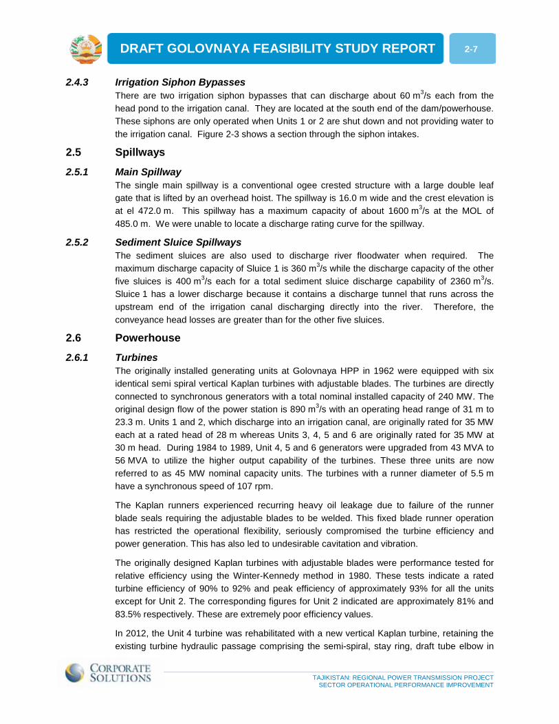


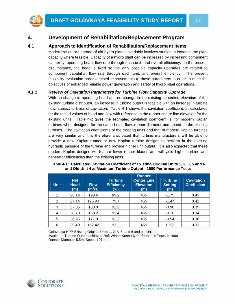


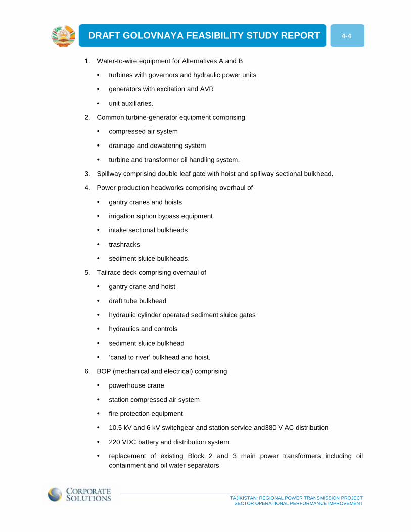


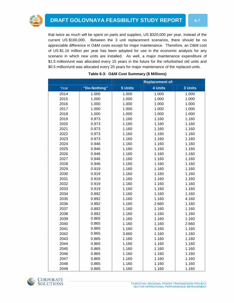


![Food Hubs Feasibility Study [DRAFT]](https://static.documents.pub/doc/80x56/586a08771a28abd9158b54a3/food-hubs-feasibility-study-draft.jpg)
![Food Hubs Feasibility Study [DRAFT] - IN.gov](https://static.documents.pub/doc/80x56/61eff6ed2dbf87069f3c87d9/food-hubs-feasibility-study-draft-ingov.jpg)


