This lecture gives a brief introduction to beam welding and cutting techniques of aluminium; it describes the process principle of electron and laser beam welding and cutting of aluminium; it gives some information about the choice of welding and cutting parameters; it also gives information about the weldability of aluminium alloys with electron beam welding. General mechanical engineering background and basic knowledge of electron and laser beam physics is assumed.
14
TALAT Lecture 4300 Beam Welding Processes of Aluminium 14 pages, 14 figures Basic Level prepared by Ulrich Krüger, Schweißtechnische Lehr- und Versuchsanstalt Berlin Objectives: − to give a brief introduction to beam welding and cutting techniques of aluminium − to describe the process principle of electron and laser beam welding and cutting of aluminium − to give some information about the choice of welding and cutting parameters − to give information about the weldability of aluminium alloys with electron beam welding Prerequisites: − General mechanical engineering background − basic knowledge of electron and laser beam physics Date of Issue: 1994 EAA - European Aluminium Association
Transcript
TALAT Lecture 4300
Beam Welding Processes of Aluminium
14 pages, 14 figures
Basic Level
prepared by Ulrich Krüger, Schweißtechnische Lehr- und Versuchsanstalt Berlin
Objectives: − to give a brief introduction to beam welding and cutting techniques of aluminium − to describe the process principle of electron and laser beam welding and cutting of
aluminium − to give some information about the choice of welding and cutting parameters − to give information about the weldability of aluminium alloys with electron beam
welding Prerequisites: − General mechanical engineering background − basic knowledge of electron and laser beam physics Date of Issue: 1994 EAA - European Aluminium Association
TALAT 4300 2
4300 Beam Welding Processes of Aluminium Table of Contents 4300 Beam Welding Processes of Aluminium..................................................2
4300.01 Electron Beam Welding............................................................................ 3
Operating Principle of an Electron Beam Welding Equipment ...............................3
Process Steps of the Deep Welding Process ............................................................4
Electron Beam Welding of Butt Joints ....................................................................4
Terms Used for Describing a Weld..........................................................................5
Electron Beam Weldability of Aluminium Alloys...................................................6
Electron Beam Welds in Aluminium Alloys ...........................................................7
Rate of Vaporisation during Electron Beam Welding of 7050 (AlZnMgCu)..........7
Tensile Strength of Electron Beam Welded 7050 (AlZnMgCu) .............................8
4300.05 List of Figures............................................................................................ 14
TALAT 4300 3
4300.01 Electron Beam Welding
♦ Operating principle of an electron beam welding equipment ♦ Process steps of the deep welding process ♦ Electron beam welding of butt joints ♦ Terms used for describing a weld ♦ Electron beam weldability of aluminium alloys ♦ Electron beam welds in aluminium alloys ♦ Rate of vaporisation during electron beam welding of 7050 (AlZnMgCu) ♦ Tensile strength of electron beam welded 7050 (AlZnMgCu)
Operating Principle of an Electron Beam Welding Equipment The electron beam welding is associated with energy densities of > 108 W/cm2. A vaporisation of the metal occurs above 106. The electrons emitted from an incandescent electrode and accelerated in an electron gun are focussed to bombard the work placed in a vacuum chamber. An arrangement of deflecting systems is used to make the beam move. The work can also be moved along different axes, so that the welding location is accessible (Figure 4300.01.01). Welding can be carried out with or without a filler metal .
Operating Principle of an Electron Beam Welding Equipment 4300.01.01
Operating Principle of anElectron Beam Welding Equipment
Cathode
Control Electrodes
Anode
Focussing Lens
Deflection System
Moving Equipment
Workpiece
pE
pA
pE
pA
alu
Training in Aluminium Application Technologies
TALAT 4300 4
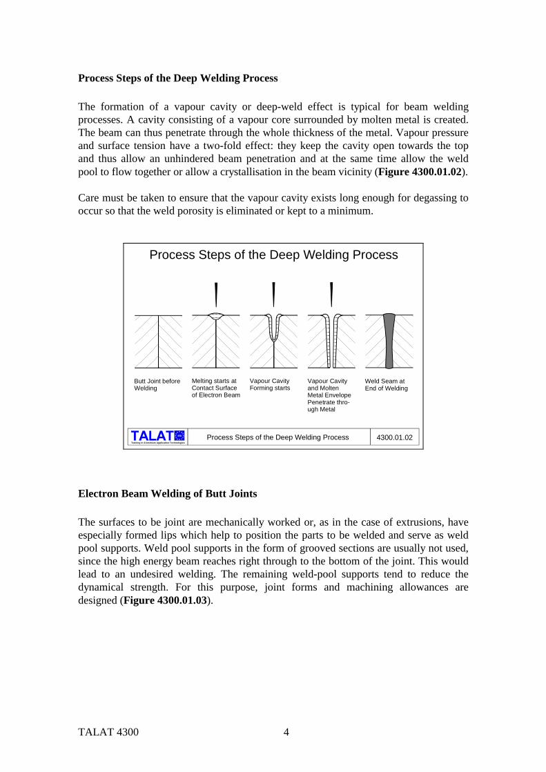
Process Steps of the Deep Welding Process The formation of a vapour cavity or deep-weld effect is typical for beam welding processes. A cavity consisting of a vapour core surrounded by molten metal is created. The beam can thus penetrate through the whole thickness of the metal. Vapour pressure and surface tension have a two-fold effect: they keep the cavity open towards the top and thus allow an unhindered beam penetration and at the same time allow the weld pool to flow together or allow a crystallisation in the beam vicinity (Figure 4300.01.02). Care must be taken to ensure that the vapour cavity exists long enough for degassing to occur so that the weld porosity is eliminated or kept to a minimum.
Process Steps of the Deep Welding Process
Process Steps of the Deep Welding Process 4300.01.02
Butt Joint beforeWelding
Melting starts atContact Surface of Electron Beam
Vapour Cavity Forming starts
Vapour Cavity and MoltenMetal EnvelopePenetrate thro-ugh Metal
Weld Seam atEnd of Welding
alu
Training in Aluminium Application Technologies
Electron Beam Welding of Butt Joints The surfaces to be joint are mechanically worked or, as in the case of extrusions, have especially formed lips which help to position the parts to be welded and serve as weld pool supports. Weld pool supports in the form of grooved sections are usually not used, since the high energy beam reaches right through to the bottom of the joint. This would lead to an undesired welding. The remaining weld-pool supports tend to reduce the dynamical strength. For this purpose, joint forms and machining allowances are designed (Figure 4300.01.03).
TALAT 4300 5
Electron Beam Welding of Butt Joints 4300.01.03
Electron Beam Welding of Butt Joints
a
s tc 1
c 2
t
>2
tz
t
alu
Training in Aluminium Application Technologies
Terms Used for Describing a Weld Joints made by the electron beam welding process are characteristically extremely narrow and deep. The ratio of weld thickness (throat of seam) to weld width lies between 5:1 to 25:1. Thus it is possible to weld even thick sheets with a square butt joint with the electron beam welding process where the other welding processes would require large V-angles and filler metal (Figure 4300.01.04).
Training in Aluminium Application Technologies
alu
We l
d R
einf
orce
men
t (ov
e rfil
l)
Joint Gap (Groove) End Crater
Roo
t Rei
nfor
cem
ent
Weld Length
Dummy Weld
Fused Zone
Bottom Weld Bead(Root) Fused Zone Base
Unwelded Gap
Weld Length
Fuse
d Zo
ne
Dep
th
Wel
d Th
ickn
ess
( Thr
oat o
f Sea
m )
W
e ld
T hic
k nes
s
Top Weld Bead
Terms used for Describing a Weld
(ove
rfill)
Terms Used for Describing a Weld 4300.01.04
Weld Width
TALAT 4300 6
Besides the terms normally used for describing weld joints, one also uses terms like fused zone base and weld thickness or throat of seam, which are specific for electron beam welding. Besides welding, it is also possible to use a reduced beam power for surface treatments like remelting, hardening, engraving etc.
Electron Beam Weldability of Aluminium Alloys Generally, aluminium and its alloys can be welded easily with the electron beam welding process. Among the non-heat-treatable alloys, the hot-cracking tendency increases with increasing magnesium content. At the same time, the high vapour pressure of magnesium increases the danger of porosity in welds. Similar to the metallurgical conditions for fusion welding processes (TIG, MIG), the cracking tendency depends on the contents of magnesium and silicon. As far as possible, the alloy AlMg3 should be avoided. The heat-treatable alloys have only a limited suitability. The high vapour pressure of zinc leads unavoidably to weld porosity. Due to the reduced heat input, the alloys containing copper can be easily welded (the weldability of copper-containing alloys with other welding processes is poor). Alloys which can be naturally aged exhibit an increase in hardness after welding, without, however, attaining the original hardness fully (Figure 4300.01.05).
Electron Beam Weldability of Aluminium Alloys 4300.01.05
Electron Beam Weldability of Aluminium AlloysAlloy Group Alloy Example Weldability
Non-Heat-TreatableWrought Alloys
Heat-TreatableWrought Alloys
Non-Heat-TreatableCasting Alloys
Heat-TreatableCasting Alloys
Al 99,5 AlMn 1 AlMg 3 AlMg 5
AlMgSi 1 AlCuMg 2 AlZnMgCu
G-AlSi 12 G-AlSi 9 Cu 3 G-AlMg 5
G-AlSi 7 Mg G-AlMg 5 Si G-AlCu 4 Ti GD-AlSi 8 Cu 3
GoodGoodHot Cracking TendencyGood, Vaporisation Loss of Mg, Weld Porosity Tendency
GoodGoodNot Suitable, Vaporisation Loss of Zn and Mg, Porosity,Hot Cracking
GoodGoodGood, Vaporisation Loss of Mg, Weld Porosity Tendency
GoodGood, Vaporisation Loss of Mg, Weld Porosity TendencyHot Cracking TendencyWeld Porosity
alu
Training in Aluminium Application Technologies
TALAT 4300 7
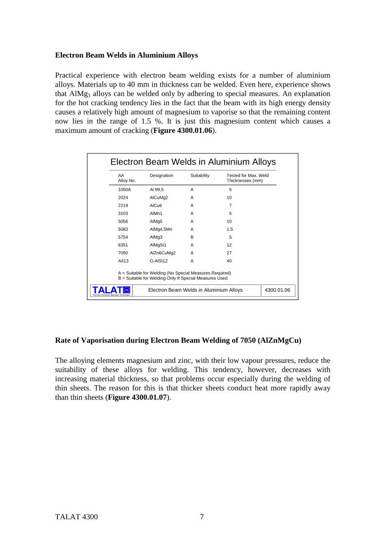
Electron Beam Welds in Aluminium Alloys Practical experience with electron beam welding exists for a number of aluminium alloys. Materials up to 40 mm in thickness can be welded. Even here, experience shows that AlMg3 alloys can be welded only by adhering to special measures. An explanation for the hot cracking tendency lies in the fact that the beam with its high energy density causes a relatively high amount of magnesium to vaporise so that the remaining content now lies in the range of 1.5 %. It is just this magnesium content which causes a maximum amount of cracking (Figure 4300.01.06).
Electron Beam Welds in Aluminium Alloys 4300.01.06
Electron Beam Welds in Aluminium AlloysAA Designation Suitability Tested for Max. WeldAlloy No. Thicknesses (mm)
1050A Al 99,5 A 5
2024 AlCuMg2 A 10
2219 AlCu6 A 7
3103 AlMn1 A 5
5056 AlMg5 A 10
5083 AlMg4,5Mn A 1.5
5754 AlMg3 B 5
6351 AlMgSi1 A 12
7050 AlZn6CuMg2 A 27
A413 G-AlSi12 A 40
A = Suitable for Welding (No Special Measures Required)B = Suitable for Welding Only If Special Measures Used
alu
Training in Aluminium Application Technologies
Rate of Vaporisation during Electron Beam Welding of 7050 (AlZnMgCu) The alloying elements magnesium and zinc, with their low vapour pressures, reduce the suitability of these alloys for welding. This tendency, however, decreases with increasing material thickness, so that problems occur especially during the welding of thin sheets. The reason for this is that thicker sheets conduct heat more rapidly away than thin sheets (Figure 4300.01.07).
TALAT 4300 8
Rate of Vaporisation during Electron Beam Welding of 7050 (AlZnMgCu)
Rate of Vaporisation during Electron Beam Welding of 7050 (AlZnMgCu) 4300.01.07
Source: Koy, Derudi
Plate Thickness [mm]
Rat
e of
Vap
oris
atio
n [%
]
50
40
30
20
10
06 10 14 20 27
∆ Mg
∆ Zn
alu
Training in Aluminium Application Technologies
Tensile Strength of Electron Beam Welded 7050 (AlZnMgCu) Electron beam welded joints of the alloy 7050 (AlZnMgCu) exhibit weld performance factors which vary with rolling direction and thickness of the material. The unshaded third columns in (Figure 4300.01.08) show that the weld performance factors for samples transverse to the rolling direction is almost equal to 1 for the 6 mm and 27 mm thick samples (i.e., the weld joint has a tensile strength almost equal to that of the base material). The weld performance factors of the longitudinal samples is almost independent of the thickness and is about 80 %.
Tensile Strength of Electron Beam Welded7050 (AlZnMgCu)
Tensile Strength of Electron Beam Welded Alloy 7050 4300.01.08
*) Weld Performance Factor
500
400
300200100
0Tens
ile S
treng
th in
[N/m
m²] DIRECTION OF ROLLING
LONGITUDINALTRANSVERSE TRANSVERSE
99,8% *)
77,9% 80,1% 77,8%93,4%
6,0 10,0 14,0 20,0 27,0
Base Material Weld Seam Min/Max Value
Thickness in [mm]
alu
Training in Aluminium Application Technologies
TALAT 4300 9
4300.02 Laser Welding
♦ Principle of a solid-state laser ♦ Comparison between electron beam welding and laser welding
Principle of a Solid-State Laser Similar to electron beam welding, the laser beam is also a high-energy source (maximum energy 109 W/cm2). For welding purposes, a lower energy is used (between 106 to 108 W/cm2) since a higher energy would lead to increased vaporisation of metals causing a weakening of the laser beam. In contrast to the electron beam welding, the laser can be used under normal atmospherical conditions without losing its energy. The laser can be utilised for both, welding and cutting. Two types of lasers are generally used:
Currently, the maximum energies of the laser types used are 1.0 to 1.5 kW for the solid-state laser, and 20 to 25 kW for the CO2 laser. Consequently, the solid-state laser is used for thinner sheets and the CO2
laser for thicker ones. The solid-state laser has a small wavelength (ca. 1.06 µm) making it possible to use flexible light-conducting cables. The solid-state laser can thus be guided much more easily than the CO2 laser which requires an arrangement of mirrors.
Principle of a Solid-State Laser
Principle of a Solid-State Laser 4300.02.01alu
Training in Aluminium Application Technologies
Flash Lamp
Nd-YAG Rod EllipsoidalMirrorPumping Equipment
Power Gauge
99 % ReflectingMirror
Semi-TransparentMirror
Beam Absorberand Stopper
BeamDiversion
FocussingMirror
ObservationOptic
TALAT 4300 10
Comparison between Electron Beam Welding and Laser Welding One of the main advantages of laser welding over electron beam welding is that the handling of the former is technologically simpler and the welding process can be conducted under atmospherical conditions. The laser welding equipment has a relatively simple mechanical construction and a higher welding accessibility making it highly flexible. In this respect, the vacuum chamber required for electron beam welding poses strong limitations on the process. On the other hand, the vacuum conditions existing in the electron beam welding process inhibit the formation of plasma streams which tend to reduce the welding performance. Thus, much higher weld penetrations can be attained than with laser welding (Figure 4300.02.02). Multistation welding machines can be used for laser welding, thereby increasing productivity and decreasing costs per piece.
Training in Aluminium Application Technologies
alu Comparison between Electron Beam Welding and Laser Welding 4300.02.02
Comparison between Electron Welding and Laser WeldingComparing parameter
Maximum beam energy of equipmentusually used in industryMaximum fused zone thickness
Welding atmosphere
Effect of energy absorption
Effect of focus diameter and focus positionon beam energy
Possibility of welding magnetic materials
Possibility of welding non-ferrous metals
Possibility of welding non-metallic materialsBeam deflection/ redirection
Multistation operation (time sharing) possibleAdaptability to other
EB
60 kW
150 mm
vacuum 10 ; 10 hPa-2 -4
depending on material(Z-number) and fused zonethickness very high
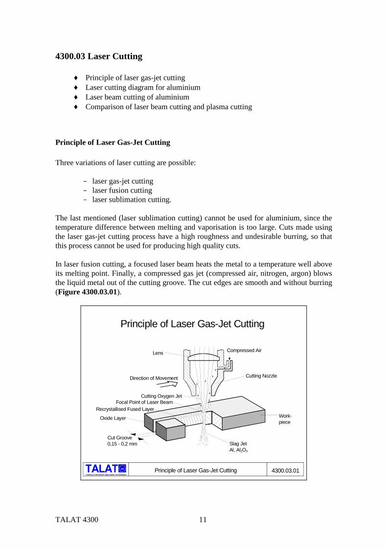
The last mentioned (laser sublimation cutting) cannot be used for aluminium, since the temperature difference between melting and vaporisation is too large. Cuts made using the laser gas-jet cutting process have a high roughness and undesirable burring, so that this process cannot be used for producing high quality cuts. In laser fusion cutting, a focused laser beam heats the metal to a temperature well above its melting point. Finally, a compressed gas jet (compressed air, nitrogen, argon) blows the liquid metal out of the cutting groove. The cut edges are smooth and without burring (Figure 4300.03.01).
Principle of Laser Gas-Jet Cutting
Principle of Laser Gas-Jet Cutting 4300.03.01
Lens Compressed Air
Cutting NozzleDirection of Movement
Work-piece
Slag JetAl, Al2O3
Cut Groove0,15 - 0,2 mm
Cutting Oxygen JetFocal Point of Laser Beam
Recrystallised Fused Layer
Oxide Layer
alu
Training in Aluminium Application Technologies
TALAT 4300 12
Laser Cutting Diagram for Aluminium As a general rule, aluminium alloys can be more easily cut than pure aluminium . The reason for this is the higher absorption, i.e., heat losses are lower (Figure 4300.03.02).
Training in Aluminium Application Technologies
alu Laser Cutting Diagram for Aluminium 4300.03.02
Laser Cutting Diagram for Aluminium
0 1 2 3 4 5 6 7Material Thickness [ mm ]
0
1
2
3
4
5
6
7
Feed
[ m
/min
]
Al Alloy
Pure Al
Laser Beam Cutting of Aluminium In contrast to steel, the cutting speed of aluminium is vastly reduced with increasing sheet thickness. The reason for this is once again the higher heat conduction loss. Laser gas-jet cutting using oxygen instead of compressed air hardly improves the cutting speed. The reaction energy of oxygen combustion freed during the laser gas-jet cutting process is only partly taken up by the metal. The simultaneously occurring oxidation of the metal surface prevents this. The quality of cut is worse than with compressed air. Undercuttings and burring cannot be avoided (Figure 4300.03.03).
Training in Aluminium Application Technologies
alu Laser Beam Cutting of Aluminium
Laser Beam Cutting of Aluminium
Material Thickness [ mm ]
Feed
[ m
/min
]
2 4 6 81
2
3
4
5 6060 ( AlMgSi 0,5 ) T6Cutting Gas O2 Compressed AirLens : 100 mm Focal LengthLaser : CO2 , 2 kW
6
4300.03.03
TALAT 4300 13
Comparison of Laser Beam Cutting and Plasma Cutting Laser beam cutting is mostly used for thin sheets. The heat input and consequently the distortion is lower than with plasma cutting. Cuts with complicated geometries which require no finishing or supplementary operations can be made with the laser cutting process (Figure 4300.03.04).
Training in Aluminium Application Technologies
alu Comparison of Laser Beam Cutting and Plasma Cutting 4300.03.04
Comparison of Laser Beam Cutting and Plasma Cutting
5
Sheet Thickness mm
600 W
1500 W
600 W
50 A 5 kW
250 A 25 kW
500 A 150 kW
1500 W
1500 W
Plas
ma
Lase
r
3
4
6
8
10
12
40 70150
5 6
10 25
Steel
Cr-Ni Steel
Aluminium
Steel
Cr-Ni Steel
Aluminium
1 10 100 1000
Source: Messer-Griesheim
Plasma cutting is ideal for cases in which high quantities are required. The high energy plasma cutting process allows higher cutting speeds, but with lower cut surface qualities and higher distortions than the laser.
TALAT 4300 14
4300.04 Literature/References - Aluminium-Taschenbuch, 14. Auflage, 1984, Aluminium-Verlag, Düsseldorf Schulz, H. Elektronenstrahlschweißen. Fachbuchreihe Schweißtechnik Nr. 93, Deutscher Verlag für Schweißtechnik 1989, Düsseldorf - Laserstrahltechnologien in der Schweißtechnik. Fachbuchreihe Schweißtechnik Nr. 86, Deutscher Verlag für Schweißtechnik 1989, Düsseldorf
4300.05 List of Figures Figure No. Figure Title (Overhead) 4300.01.01
Operating Principle of an Electron Beam Welding Equipment
4300.01.02 Process Steps of the Deep Welding Process 4300.01.03 Electron Beam Welding of Butt Joints 4300.01.04 Terms Used for Describing a Weld 4300.01.05 Electron Beam Weldability of Aluminium Alloys 4300.01.06 Electron Beam Welds of Aluminium Alloys 4300.01.07 Rate of Vaporisation during Electron Beam Welding of 7050
(AlZnMgCu) 4300.01.08 Tensile Strength of Electron Beam Welded 7050 (AlZnMg Cu) 4300.02.01
Principle of a Solid-State Laser
4300.02.01 Comparison between Electron Beam Welding and Laser Welding 4300.03.01
Principle of Laser Gas-Jet Cutting
4300.03.02 Laser Cutting Diagram for Aluminium 4300.03.03 Laser Beam Cutting of Aluminium 4300.03.04 Comparison of Laser Beam Cutting and Plasma Cutting