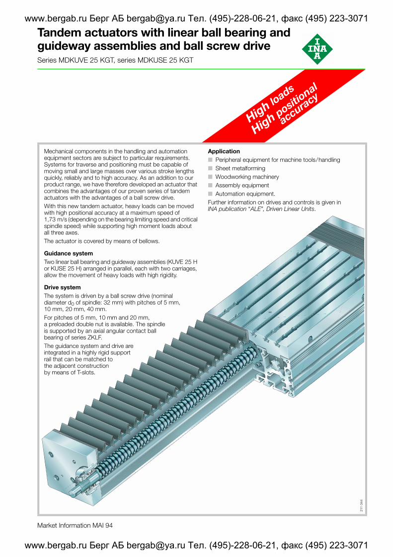
Market Information MAI 94 High loads High positional accuracy Tandem actuators with linear ball bearing and guideway assemblies and ball screw drive Series MDKUVE 25 KGT, series MDKUSE 25 KGT Mechanical components in the handling and automation equipment sectors are subject to particular requirements. Systems for traverse and positioning must be capable of moving small and large masses over various stroke lengths quickly, reliably and to high accuracy. As an addition to our product range, we have therefore developed an actuator that combines the advantages of our proven series of tandem actuators with the advantages of a ball screw drive. With this new tandem actuator, heavy loads can be moved with high positional accuracy at a maximum speed of 1,73 m/s (depending on the bearing limiting speed and critical spindle speed) while supporting high moment loads about all three axes. The actuator is covered by means of bellows. Guidance system Two linear ball bearing and guideway assemblies (KUVE 25 H or KUSE 25 H) arranged in parallel, each with two carriages, allow the movement of heavy loads with high rigidity. Drive system The system is driven by a ball screw drive (nominal diameter d 0 of spindle: 32 mm) with pitches of 5 mm, 10 mm, 20 mm, 40 mm. For pitches of 5 mm, 10 mm and 20 mm, a preloaded double nut is available. The spindle is supported by an axial angular contact ball bearing of series ZKLF. The guidance system and drive are integrated in a highly rigid support rail that can be matched to the adjacent construction by means of T-slots. 211 044 Application ■ Peripheral equipment for machine tools/handling ■ Sheet metalforming ■ Woodworking machinery ■ Assembly equipment ■ Automation equipment. Further information on drives and controls is given in INA publication “ALE”, Driven Linear Units. www.bergab.ru Берг АБ [email protected]Тел. (495)-228-06-21, факс (495) 223-3071 www.bergab.ru Берг АБ [email protected]Тел. (495)-228-06-21, факс (495) 223-3071
Transcript
Market Information MAI 94
High loads
High positional
accuracy
Tandem actuators with linear ball bearing and guideway assemblies and ball screw driveSeries MDKUVE 25 KGT, series MDKUSE 25 KGT
Mechanical components in the handling and automation equipment sectors are subject to particular requirements. Systems for traverse and positioning must be capable of moving small and large masses over various stroke lengths quickly, reliably and to high accuracy. As an addition to our product range, we have therefore developed an actuator that combines the advantages of our proven series of tandem actuators with the advantages of a ball screw drive.With this new tandem actuator, heavy loads can be moved with high positional accuracy at a maximum speed of 1,73 m/s (depending on the bearing limiting speed and critical spindle speed) while supporting high moment loads about all three axes.The actuator is covered by means of bellows.
Guidance systemTwo linear ball bearing and guideway assemblies (KUVE 25 H or KUSE 25 H) arranged in parallel, each with two carriages, allow the movement of heavy loads with high rigidity.
Drive systemThe system is driven by a ball screw drive (nominal diameter d0 of spindle: 32 mm) with pitches of 5 mm, 10 mm, 20 mm, 40 mm.For pitches of 5 mm, 10 mm and 20 mm, a preloaded double nut is available. The spindle is supported by an axial angular contact ball bearing of series ZKLF.The guidance system and drive are integrated in a highly rigid support rail that can be matched to the adjacent construction by means of T-slots.
211
044
Application■ Peripheral equipment for machine tools/handling■ Sheet metalforming■ Woodworking machinery■ Assembly equipment■ Automation equipment.Further information on drives and controls is given in INA publication “ALE”, Driven Linear Units.
www.bergab.ru Берг АБ [email protected] Тел. (495)-228-06-21, факс (495) 223-3071
www.bergab.ru Берг АБ [email protected] Тел. (495)-228-06-21, факс (495) 223-3071
2
Tandem actuator with four-row linear ball bearing and guideway assembly and ball screw driveSeries MDKUVE 25 KGT
Page
Design and safety guidelines............................... 6
Ordering example and ordering designation ....... 12
Features
Tandem actuators with four-row linear ball bearing and guideway assembly and ball screw drive■ are complete units comprising:
– a support rail – the supporting profiled section is extremely rigid and suitable for spanning large gaps
– one carriage running in the support rail – KUVE guidance system with four carriages
– one ball screw drive■ are suitable for moderate to heavy loads about all three
axes■ can be fitted with a second, non-driven carriage in order
to support high moments ■ have two guidance systems preloaded free from
clearance■ run with high positional accuracy and free from stick-slip.
In conjunction with the servocontroller COMPAX, the following positional accuracies can be achieved:– � �0,025 mm with actuators with a preloaded double
nut (FM)– � �0,08 mm with actuators with a single nut (F)
■ are suitable for:– accelerations up to 10 m/s2
– speeds up to 1,73 m/s– spindle speeds up to 2 600 min–1
■ are protected against contamination by bellows– spindle and guidance system
■ can be simply attached to the adjacent construction by means of the T-slots in the carriage and support rail
■ are easy to maintain and require little maintenance – the lubrication points are easily accessible
■ are versatile in application due to a comprehensive range of accessories.
Carriage with ball screw drive
■ carriage plate made from anodised profiled aluminium with T-slots
■ guidance by four KWVE carriages■ drive by ball screw drive■ integral single or preloaded double nut■ funnel type lubrication nipples on longitudinal faces
Support rail
■ support rail made from anodised profiled aluminium, combined with guideways of linear ball bearing and guideway assembly KUVE
■ maximum length: 5 300 mm■ T-slots for mounting in modular constructions
– T-slots for bolts to DIN 787 and T-nuts to DIN 508
211
034
211
035
14
14
www.bergab.ru Берг АБ [email protected] Тел. (495)-228-06-21, факс (495) 223-3071
www.bergab.ru Берг АБ [email protected] Тел. (495)-228-06-21, факс (495) 223-3071
Ordering example and ordering designation ....... 13
Features
Tandem actuators with six-row linear ball bearing and guideway assembly and ball screw drive■ are complete units comprising:
– a support rail – the supporting profiled section is extremely rigid and suitable for spanning large gaps
– one carriage running in the support rail – KUSE guidance system with four carriages
– one ball screw drive■ are suitable for heavy to very heavy loads about all three
axes■ can be fitted with a second, non-driven carriage in order
to support high moments ■ have two guidance systems preloaded free from
clearance■ run with high positional accuracy and free from stick-slip.
In conjunction with the servocontroller COMPAX, the following positional accuracies can be achieved:– � �0,025 mm with actuators with a preloaded double
nut (FM)– � �0,08 mm with actuators with a single nut (F)
■ are suitable for:– accelerations up to 10 m/s2
– speeds up to 1,73 m/s– spindle speeds up to 2 600 min–1
■ are protected against contamination by bellows– spindle and guidance system
■ can be simply attached to the adjacent construction by means of the T-slots in the carriage and support rail
■ are easy to maintain and require little maintenance – the lubrication points are easily accessible
■ are versatile in application due to a comprehensive range of accessories.
Carriage with ball screw drive
■ carriage plate made from anodised profiled aluminium with T-slots
■ guidance by four KWSE carriages■ drive by ball screw drive■ integral single or preloaded double nut■ funnel type lubrication nipples on longitudinal faces
Support rail
■ support rail made from anodised profiled aluminium, combined with guideway of linear ball bearing and guideway assembly KUSE
■ maximum length: 5 300 mm■ T-slots for mounting in modular constructions
– T-slots for bolts to DIN 787 and T-nuts to DIN 508
211
016
211
032
16
16
www.bergab.ru Берг АБ [email protected] Тел. (495)-228-06-21, факс (495) 223-3071
www.bergab.ru Берг АБ [email protected] Тел. (495)-228-06-21, факс (495) 223-3071
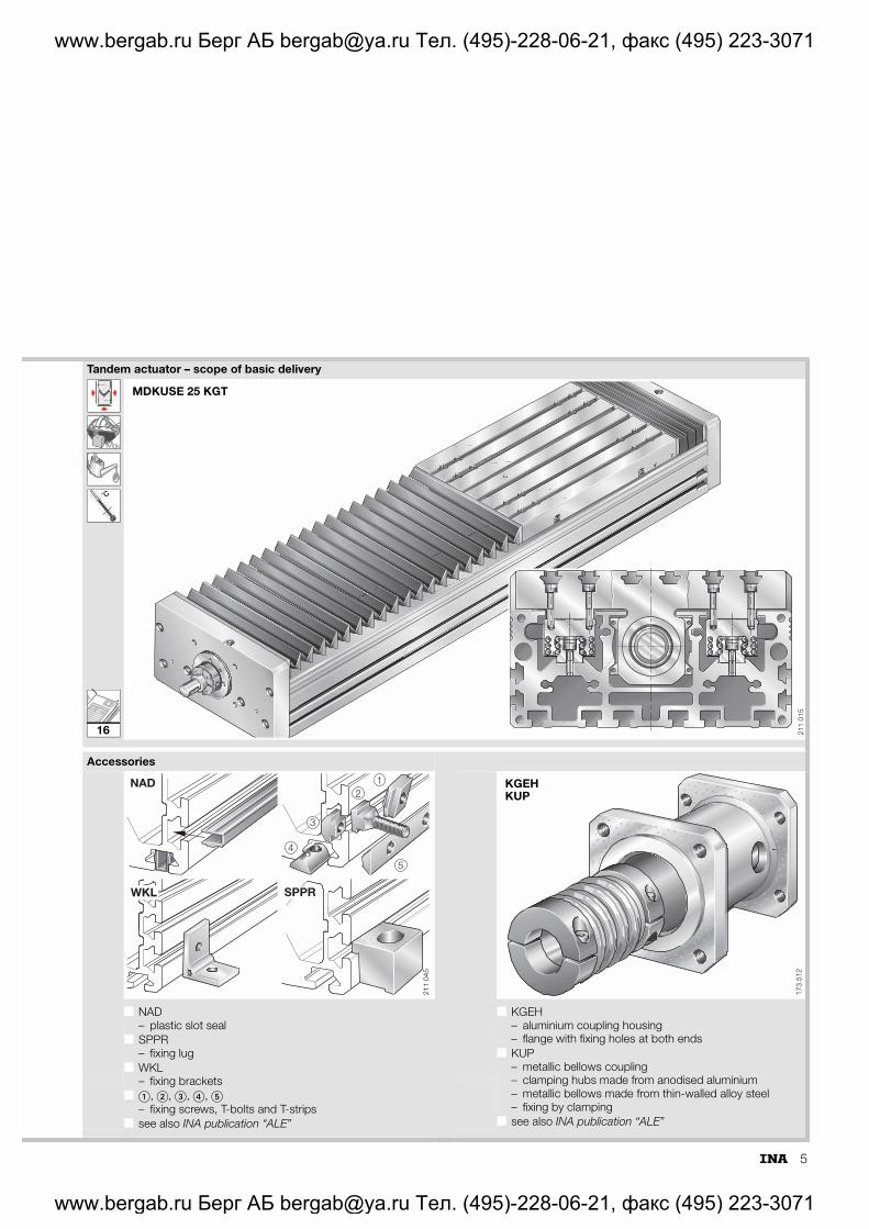
■ KGEH– aluminium coupling housing– flange with fixing holes at both ends
■ KUP– metallic bellows coupling– clamping hubs made from anodised aluminium– metallic bellows made from thin-walled alloy steel– fixing by clamping
■ see also INA publication “ALE”
MDKUSE 25 KGT
211
015
NAD
WKL SPPR
12
3
5
4
211
045
KGEHKUP
173
512
16
www.bergab.ru Берг АБ [email protected] Тел. (495)-228-06-21, факс (495) 223-3071
www.bergab.ru Берг АБ [email protected] Тел. (495)-228-06-21, факс (495) 223-3071
6
Tandem actuators with linear ball bearing and guideway assemblies and ball screw drive
Design and safety guidelinesBall screw driveThe ball screw spindle is available in the pitch sizes shown in Table 1. Single nuts have axial clearance dependent on the pitch in accordance with Table 1.The pitch accuracy of the spindle is 50 �m over a spindle length of 300 mm. On the locating bearing side, the spindle is supported by an axial angular contact ball bearing ZKLF (Figure 1). The bearing is greased and maintenance-free.For longer actuators, the permissible spindle speed can be increased by the use of one or two spindle supports (suffix SPU or 2SPU). The supports are arranged in pairs, movable and are moved by the driven carriage.
1) At a spindle speed of 2 600 min–1.
Combination with actuator componentsIn its role as a system supplier, INA offers not only actuators but also the appropriate components such as coupling housings, couplings, gearboxes and motors (Table 2). These components are precisely matched to the actuators and thus complement the range of linear actuators in an optimum manner.
K
Figure 1 · Ball screw drive with locating bearing arrangement
Table 1 · Ball screw drive variants
Ball screw drive
Nut Travel speed1)
Pitch Pzmm
Design Suffix Axial clearancemax.mm
max.m/s
5 Single nut 5 F 0,1 0,21
5 Double nut 5 FM Preloaded 0,21
10 Single nut 10 F 0,1 0,43
10 Double nut 10 FM Preloaded 0,43
20 Single nut 20 F 0,1 0,87
20 Double nut 20 FM Preloaded 0,87
40 Single nut 40 F 0,1 1,73
211
033
Table 2 · Possible combinations with actuator components
Tandem actuator Coupling housing Coupling Gearbox
MDKUVE 25 KGTMDKUSE 25 KGT
KGEH MKUE 25 KGT-110/130/M8 KUP 560-56 19H7-25H7 GETR PL 115-..
KGEH MKUE 25 KGT-95/115/M8 KUP 50-40-2 19H7-19H7 –
KGEH MKUE 25 KGT-80/100/M8 KUP 560-56 19H7-20H7 GETR PL 90-..
KGEH MKUE 25 KGT-130/165/M10 KUP 560-56 19H7-24H7 –
www.bergab.ru Берг АБ [email protected] Тел. (495)-228-06-21, факс (495) 223-3071
www.bergab.ru Берг АБ [email protected] Тел. (495)-228-06-21, факс (495) 223-3071
7
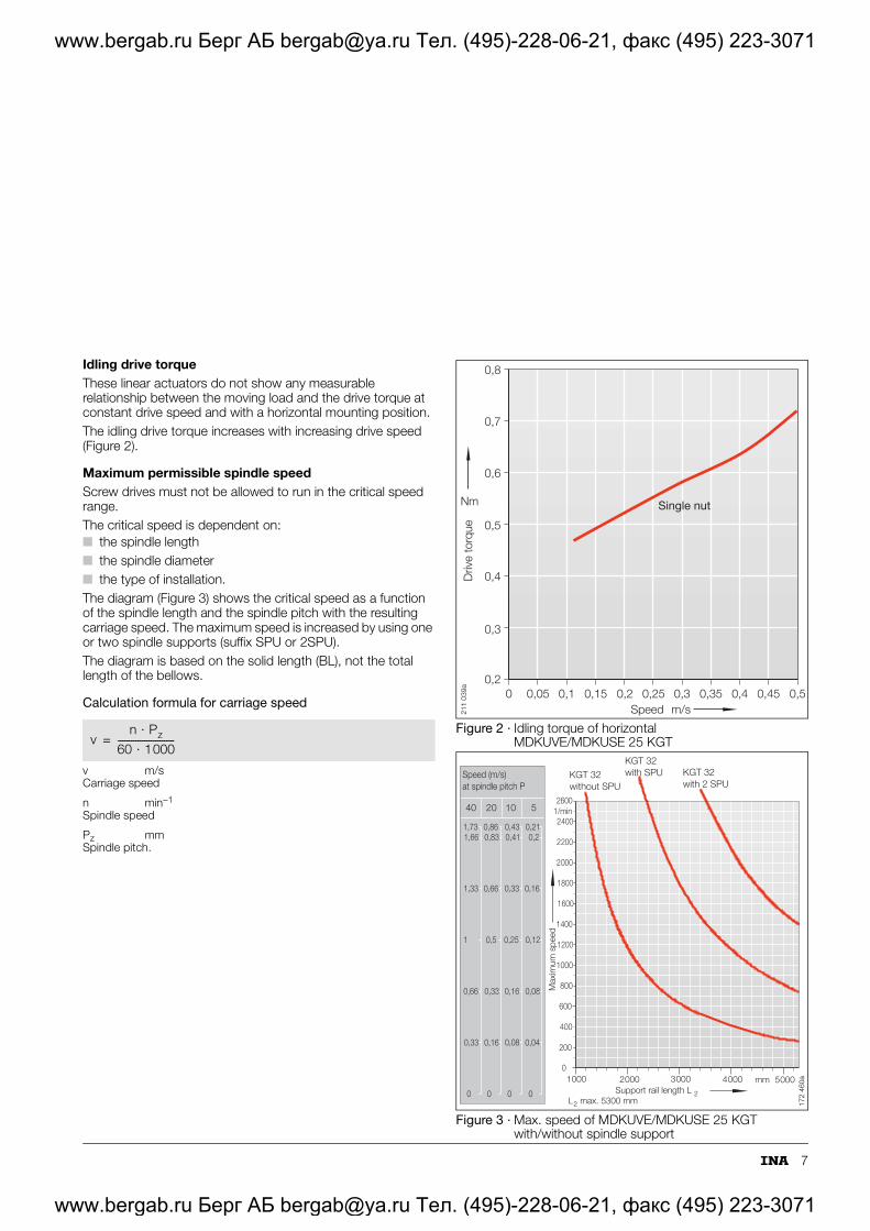
Idling drive torqueThese linear actuators do not show any measurable relationship between the moving load and the drive torque at constant drive speed and with a horizontal mounting position.The idling drive torque increases with increasing drive speed (Figure 2).
Maximum permissible spindle speedScrew drives must not be allowed to run in the critical speed range.The critical speed is dependent on:■ the spindle length■ the spindle diameter■ the type of installation.The diagram (Figure 3) shows the critical speed as a function of the spindle length and the spindle pitch with the resulting carriage speed. The maximum speed is increased by using one or two spindle supports (suffix SPU or 2SPU).The diagram is based on the solid length (BL), not the total length of the bellows.
Calculation formula for carriage speed
v m/sCarriage speed
n min–1
Spindle speed
Pz mmSpindle pitch.
Figure 2 · Idling torque of horizontal MDKUVE/MDKUSE 25 KGT
Figure 3 · Max. speed of MDKUVE/MDKUSE 25 KGT with/without spindle support
www.bergab.ru Берг АБ [email protected] Тел. (495)-228-06-21, факс (495) 223-3071
www.bergab.ru Берг АБ [email protected] Тел. (495)-228-06-21, факс (495) 223-3071
8
Tandem actuators with linear ball bearing and guideway assemblies and ball screw drive
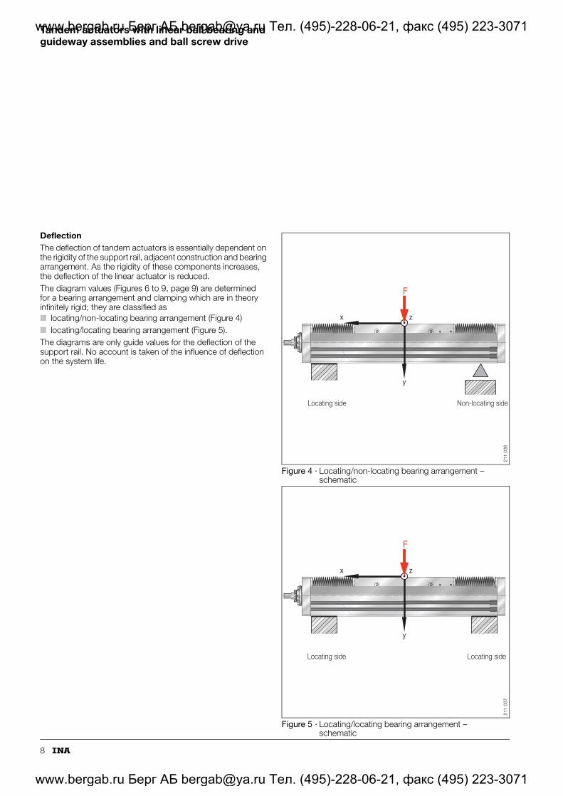
DeflectionThe deflection of tandem actuators is essentially dependent on the rigidity of the support rail, adjacent construction and bearing arrangement. As the rigidity of these components increases, the deflection of the linear actuator is reduced.The diagram values (Figures 6 to 9, page 9) are determined for a bearing arrangement and clamping which are in theory infinitely rigid; they are classified as■ locating/non-locating bearing arrangement (Figure 4)■ locating/locating bearing arrangement (Figure 5).The diagrams are only guide values for the deflection of the support rail. No account is taken of the influence of deflection on the system life.
www.bergab.ru Берг АБ [email protected] Тел. (495)-228-06-21, факс (495) 223-3071
www.bergab.ru Берг АБ [email protected] Тел. (495)-228-06-21, факс (495) 223-3071
9
Figure 6 · Deflection of locating/non-locating bearing arrangement with bending about Z axis
Figure 7 · Deflection of locating/locating bearing arrangement with bending about Z axis
Figure 8 · Deflection of locating/non-locating bearing arrangement with bending about Y axis
Figure 9 · Deflection of locating/locating bearing arrangement with bending about Y axis
0
0,5
1
1,5
2
2,5
3
3,5
4
0 1000 2000 3000 4000 5000 5300 6000
Length
Def
lect
ion
mm
mm
6000 N8000 N
10000 N
2000 N4000 N
1000 N
0 N500 N
MDKUSE 25 KGTMDKUVE 25 KGT
211
040
0 1000 2000 3000 4000 5000 60000
0,5
1
1,5
2
2,5
3
3,5
4
mm
mm
6000 N8000 N10000 N
2000 N4000 N
1000 N
0 N
500 N
MDKUSE 25 KGTMDKUVE 25 KGT
5 300
Length
Def
lect
ion
211
042
0 2000 4000 500030001000 6000mm
0
0,5
1
1,5
2
2,5
3
3,5
4
mm
10000 N12000 N14000 N
6000 N8000 N
MDKUSE 25 KGTMDKUVE 25 KGT
4000 N
0 N2000 N
5300
Length
Def
lect
ion
211
041
0
0,5
1
1,5
2
2,5
3
3,5
4
mm
0 2000 4000 60005000 5300
mm
10000 N
12000 N14000 N
MDKUSE 25 KGTMDKUVE 25 KGT
8000 N
6000 N
4000 N
2000 N
0 N
1000 3000Length
Def
lect
ion
211
043
www.bergab.ru Берг АБ [email protected] Тел. (495)-228-06-21, факс (495) 223-3071
www.bergab.ru Берг АБ [email protected] Тел. (495)-228-06-21, факс (495) 223-3071
10
Tandem actuators with linear ball bearing and guideway assemblies and ball screw drive
LubricationRacewaysThe rolling system (the contact zone between the rolling elements and raceways) must be lubricated.The relubrication intervals are essentially dependent on:■ the travel speed■ the load■ the operating temperature■ the stroke length■ the environmental conditions; the cleaner the operating
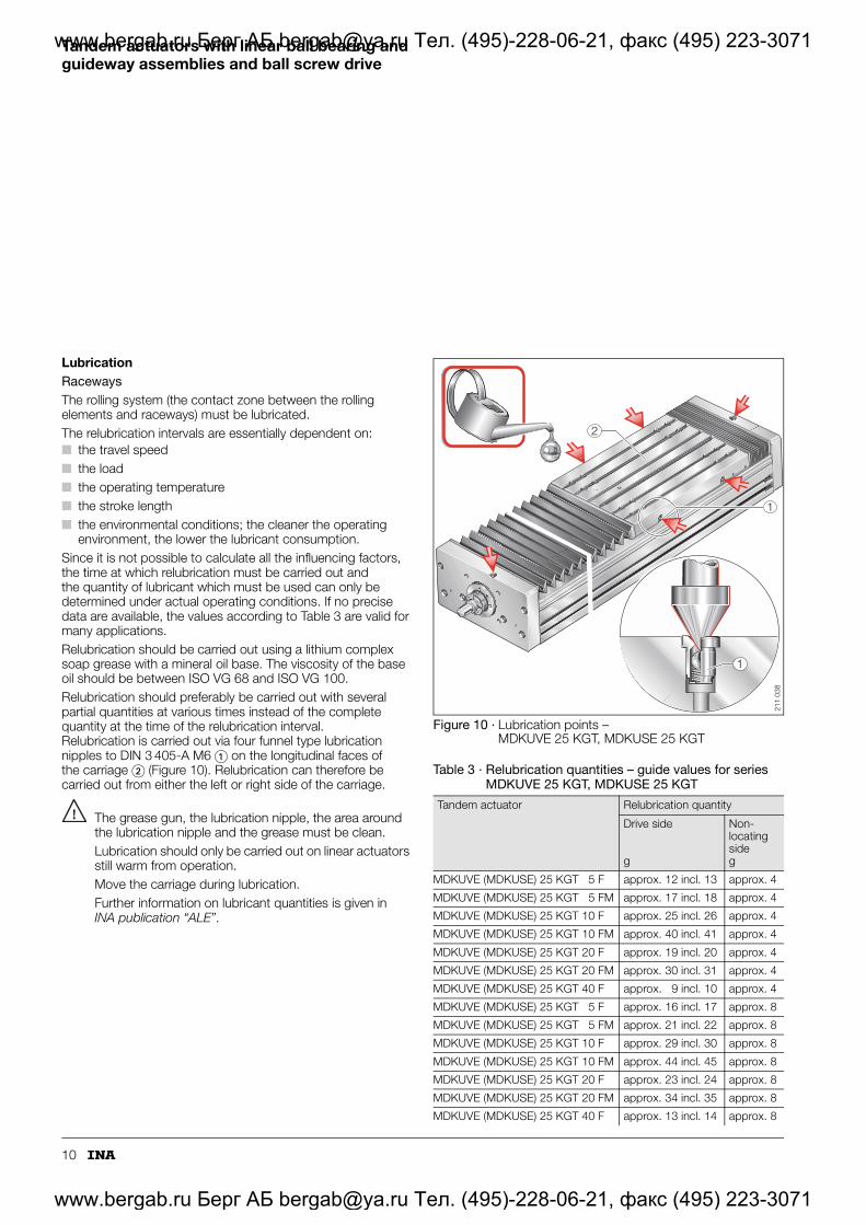
environment, the lower the lubricant consumption.Since it is not possible to calculate all the influencing factors, the time at which relubrication must be carried out and the quantity of lubricant which must be used can only be determined under actual operating conditions. If no precise data are available, the values according to Table 3 are valid for many applications.Relubrication should be carried out using a lithium complex soap grease with a mineral oil base. The viscosity of the base oil should be between ISO VG 68 and ISO VG 100.Relubrication should preferably be carried out with several partial quantities at various times instead of the complete quantity at the time of the relubrication interval. Relubrication is carried out via four funnel type lubrication nipples to DIN 3 405-A M6 � on the longitudinal faces of the carriage � (Figure 10). Relubrication can therefore be carried out from either the left or right side of the carriage.
The grease gun, the lubrication nipple, the area around the lubrication nipple and the grease must be clean.Lubrication should only be carried out on linear actuators still warm from operation.Move the carriage during lubrication. Further information on lubricant quantities is given in INA publication “ALE”.
www.bergab.ru Берг АБ [email protected] Тел. (495)-228-06-21, факс (495) 223-3071
www.bergab.ru Берг АБ [email protected] Тел. (495)-228-06-21, факс (495) 223-3071
11
AccuracyThe support rails are precision straightened and the tolerances are better than those to DIN 17 615 (Table 4 and Table 5). The tolerances are arithmetic mean values.The method for determining the straightness of the support rail is shown in Figure 11.
Figure 11 · Straightness tolerance of support rail for MDKUVE 25 KGT, MDKUSE 25 KGT
Table 4 · Length tolerance of tandem actuators
Length of actuatorLtot
Tolerance
mm mm
Ltot � 1000 �2
1000 � Ltot � 2000 �3
2000 � Ltot � 4000 �4
4000 � Ltot �5
Table 5 · Straightness tolerance of support rail
Lengthof support rail
MDKUVE 25 KGT, MDKUSE 25 KGT
t2 t3 Torsion
mm mm mm mm
� 1000 0,4 0,3 0,8
1000 � 2000 0,8 0,5 1
2000 � 3000 1,2 0,7 1,2
3000 � 4000 1,5 1 1,6
4000 � 5000 1,9 1,2 1,8
5000 � 6000 2,5 1,5 2
2t3t
211
026
www.bergab.ru Берг АБ [email protected] Тел. (495)-228-06-21, факс (495) 223-3071
www.bergab.ru Берг АБ [email protected] Тел. (495)-228-06-21, факс (495) 223-3071
12
Tandem actuators with linear ball bearing and guideway assemblies and ball screw drive
Ordering example and ordering designationFor variants of screw drives, actuators and suffixes, see Table 6.
Figure 13 · Ordering example and ordering designation – tandem actuator MDKUSE 25 KGT 5 FM SPU/3 991-3 000
Linear actuator with ball monorail guidance system MDKUSESize 25Drive by ball screw drive KGTSpindle pitch 5 mmPreloaded double nut FMSpindle support SPUTotal length Ltot 3 991 mmTotal stroke (effective stroke +2�S) 3 000 mm
Table 7 · Variants of screw drives and tandem actuators – suffixes
Drive systemSuffix
Design
5 Spindle pitch 5 mm
10 Spindle pitch 10 mm
20 Spindle pitch 20 mm
40 Spindle pitch 40 mm
F Single nut
FM Preloaded double nut (flanged and cylindrical nuts)
W2 Second, non-driven carriage
SPU One spindle support
2SPU Two spindle supports
OA Without drive (no spindle)
MDKUSE 25 KGT 5 FM SPU/3991–3000
3991
3000
211
031
www.bergab.ru Берг АБ [email protected] Тел. (495)-228-06-21, факс (495) 223-3071
www.bergab.ru Берг АБ [email protected] Тел. (495)-228-06-21, факс (495) 223-3071
14
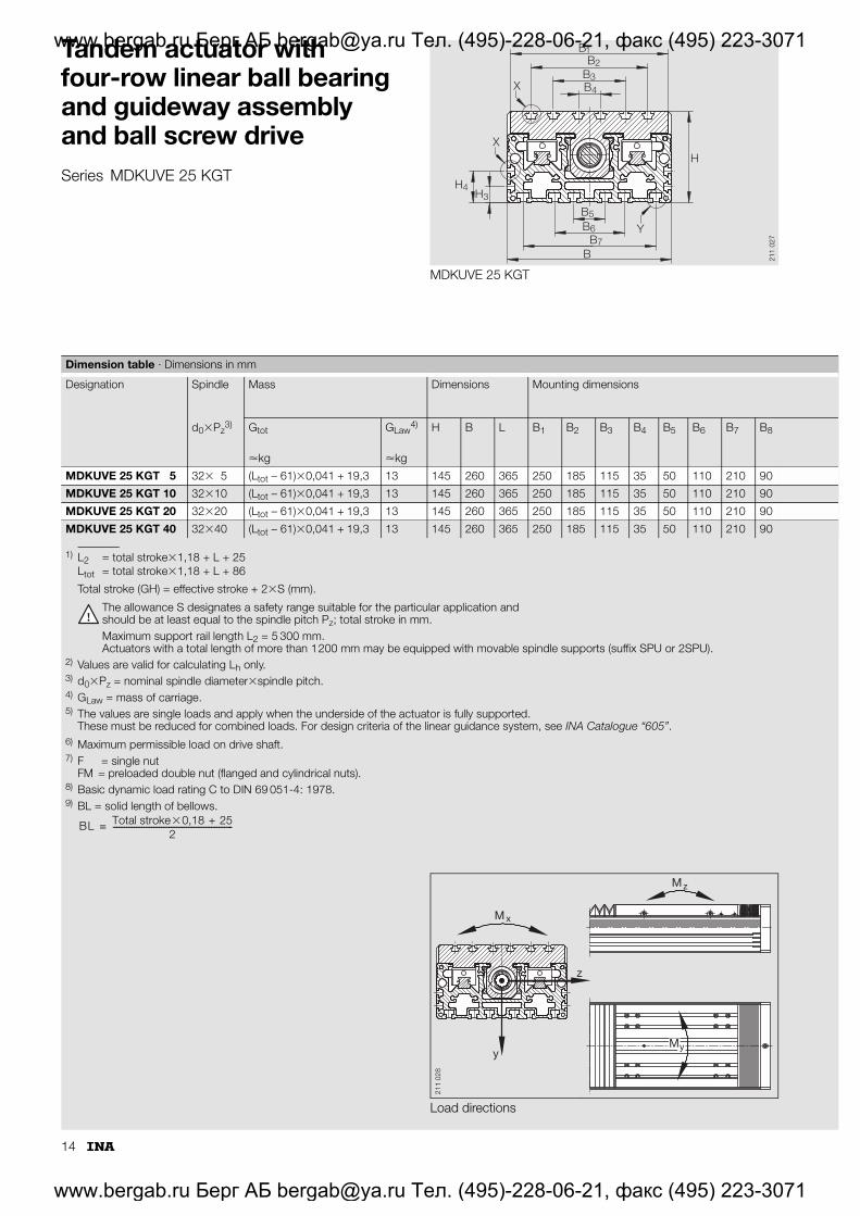
Tandem actuator with four-row linear ball bearing and guideway assembly and ball screw driveSeries MDKUVE 25 KGT
MDKUVE 25 KGT
BB2
B3B
1
H
B
H3H4
5B6
B7B
4X
Y
X
211
027
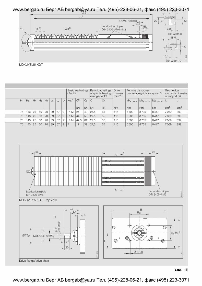
1) L2 = total stroke�1,18 + L + 25Ltot = total stroke�1,18 + L + 86
Total stroke (GH) = effective stroke + 2�S (mm).
The allowance S designates a safety range suitable for the particular application and should be at least equal to the spindle pitch Pz; total stroke in mm.Maximum support rail length L2 = 5 300 mm. Actuators with a total length of more than 1200 mm may be equipped with movable spindle supports (suffix SPU or 2SPU).
2) Values are valid for calculating Lh only.3) d0�Pz = nominal spindle diameter�spindle pitch.4) GLaw = mass of carriage.5) The values are single loads and apply when the underside of the actuator is fully supported.
These must be reduced for combined loads. For design criteria of the linear guidance system, see INA Catalogue “605”.6) Maximum permissible load on drive shaft.7) F = single nut
FM = preloaded double nut (flanged and cylindrical nuts).8) Basic dynamic load rating C to DIN 69 051-4: 1978.9) BL = solid length of bellows.
Dimension table · Dimensions in mm
Designation Spindle Mass Dimensions Mounting dimensions
www.bergab.ru Берг АБ [email protected] Тел. (495)-228-06-21, факс (495) 223-3071
www.bergab.ru Берг АБ [email protected] Тел. (495)-228-06-21, факс (495) 223-3071
16
Tandem actuator with six-row linear ball bearing and guideway assembly and ball screw driveSeries MDKUSE 25 KGT
MDKUSE 25 KGT
BB2
B3B
1
H
B
H3H4
5B6
B7B
4X
Y
X
211
017
1) L2 = total stroke�1,18 + L + 25Ltot = total stroke�1,18 + L + 86
Total stroke (GH) = effective stroke + 2�S (mm).
The allowance S designates a safety range suitable for the particular application and should be at least equal to the spindle pitch Pz; total stroke in mm.Maximum support rail length L2 = 5 300 mm. Actuators with a total length of more than 1200 mm may be equipped with movable spindle supports (suffix SPU or 2SPU).
2) Values are valid for calculating Lh only.3) d0�Pz = nominal spindle diameter�spindle pitch.4) GLaw = mass of carriage.5) The values are single loads and apply when the underside of the actuator is fully supported.
These must be reduced for combined loads. For design criteria of the linear guidance system, see INA Catalogue “605”.6) Maximum permissible load on drive shaft.7) F = single nut
FM = preloaded double nut (flanged and cylindrical nuts).8) Basic dynamic load rating C to DIN 69 051-4: 1978.9) BL = solid length of bellows.
Dimension table · Dimensions in mm
Designation Spindle Mass Dimensions Mounting dimensions