1 INSTRUCTION FOR TANK ERECTION WITH 12 TON CAPACITY JACKING EQUIPMENT TYPE 510-35D Table of contents 1. Data 2 2. Range of application of the lifting equipment 3 3. Principle of the erection system 4 4. Description and components of the jacking equipment 5 5. Oil Pump / powerpack 6 6. Auxiliary devices 7 7. Number of tank trestles 8 8. Example of tank under erection 9 9. Working procedure 10 10. Assembly of the jacking equipment and lifting 12 11. Lifting speed 13 12. Oil recommendations 14 13. Detailed instruction for installation and operation of jacking equipment 15 14. Detailed instruction for operation of powerpack 18 15. Maintenance and control instructions for jacking equipment 19 16. Preventive maintenance for powerpack 20 17. Drawings CC-1 to CC-8
Transcript
1
INSTRUCTION FOR TANK ERECTION WITH 12 TON CAPACITY JACKING EQUIPMENT TYPE 510-35D Table of contents 1. Data 2 2. Range of application of the lifting equipment 3 3. Principle of the erection system 4 4. Description and components of the jacking equipment 5 5. Oil Pump / powerpack 6 6. Auxiliary devices 7 7. Number of tank trestles 8 8. Example of tank under erection 9 9. Working procedure 10 10. Assembly of the jacking equipment and lifting 12 11. Lifting speed 13 12. Oil recommendations 14 13. Detailed instruction for installation and operation of jacking equipment 15 14. Detailed instruction for operation of powerpack 18 15. Maintenance and control instructions for jacking equipment 19 16. Preventive maintenance for powerpack 20 17. Drawings CC-1 to CC-8
2
1.0 Data 1.1 The lifting equipment is composed of a number of trestle assemblies (lifting
trestles with hydraulic climbing jacks) and one common high-pressure oil pump / powerpack.
1.2 Lifting / lowering capacity : 12 metric tons per trestle 1.3 Effective lifting height ( = maximum shell ring height ) : 2500 mm 1.4 Effective climb : 95 mm per stroke 1.5 Piston area : total 113.50 cm2 per climbing jack 1.6 Cylinder volume : 1.10 ltrs per climbing jack 1.7 Static hydraulic pressure : 110 kg/cm2 at 12 tons load 1.8 The jacks are connected to pump type :
HP-24-120 at maximum 24 tank trestles ( 7.5 HP motor ) HP-34-120 at maximum 34 tank trestles ( 10 HP motor ) HP-45-120 at maximum 55 tank trestles ( 15 HP motor ) HP-65-120 at maximum 65 tank trestles ( 20 HP motor ) HP-85-120 at maximum 85 tank trestles ( 30 HP motor ) HP-120-120 at maximum 120 tank trestles ( 40 HP motor )
3
2.0 Range of application of the lifting equipment 2.1 Erection of tanks of steel or other materials. Repairs of tanks or tank foundations Enlargement of storage capacity in existing tanks Erection of other circular structures such as reactor shields in nuclear power
stations, etc. Erection of circular gasholders
4
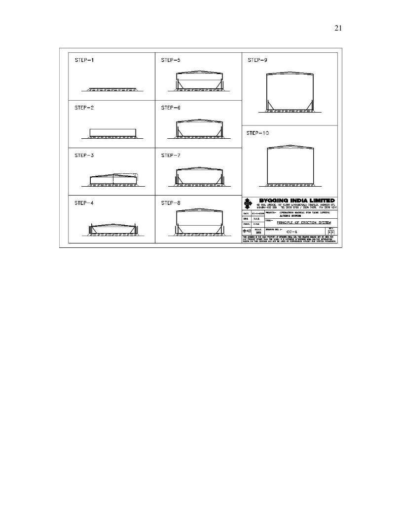
3.0 Description of principle of the erection system Drawing CC-1 and CC-2 The following short description gives the working procedure in outline. It can in certain details be modified when required.
3.1 The tank bottom-plates are placed on the prepared foundation and welded
together. 3.2 Spacers cum guide beams of maximum 400 mm height are tack welded to the
tank bottom along the periphery. The plates of the first shell ring (in fact the top ring of the tank) are positioned and welded together.
3.3 The beams or lattice work of the roof are assembled and finally joined to the
upper rim of the shell ring. Possible the inner sheets of the roof are placed and welded together.
3.4 The lifting equipment is assembled according to Chapters 10 and 13. The plates
of the second shell ring (next to top ring) are positioned outside the first one. 3.5 The completed part of the tank (the roof and top shell ring) is lifted hydraulically
to a height, at which the plates of the second shell ring can be moved into place and the roof sheeting can be completed, except for about 2 or 3 roof plates which shall not be fixed until completion of the tank for air to pass through.
3.6 The plates of the second shell ring are located exactly and welded together to the
lower edge of the first shell ring. 3.7 The plates of the third shell ring are placed outside the second shell ring. 3.8 The completed part of the tank (the roof and the two uppermost shell rings) is
lifted. 3.9 The above cycle of operations is repeated until the last (bottom) shell ring is
finished. 3.10 The entire tank is lowered down to the bottom plates and welded to this. The
lifting equipment is dismantled.
5
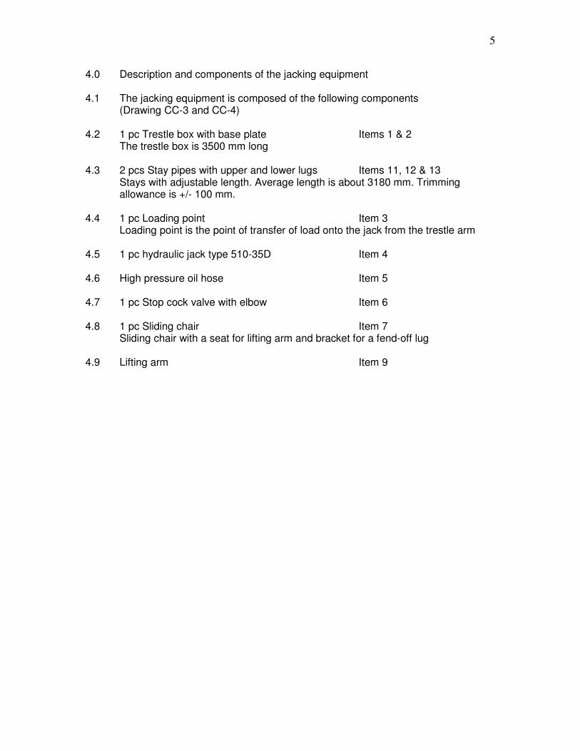
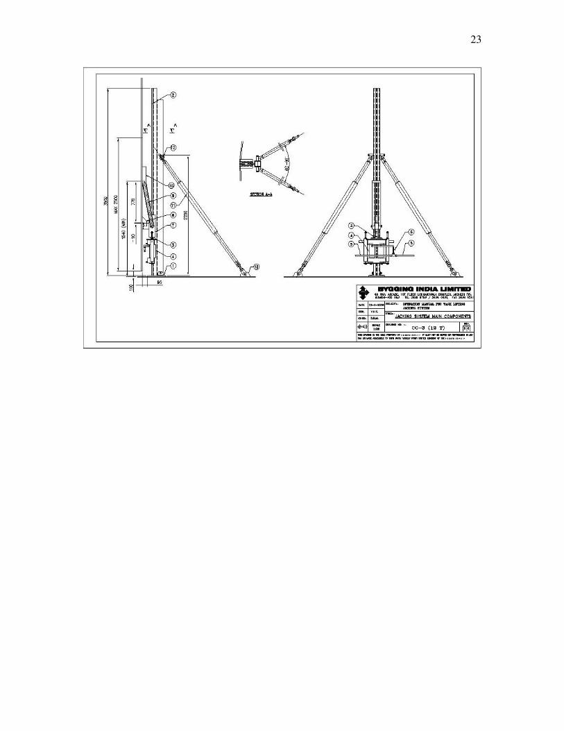
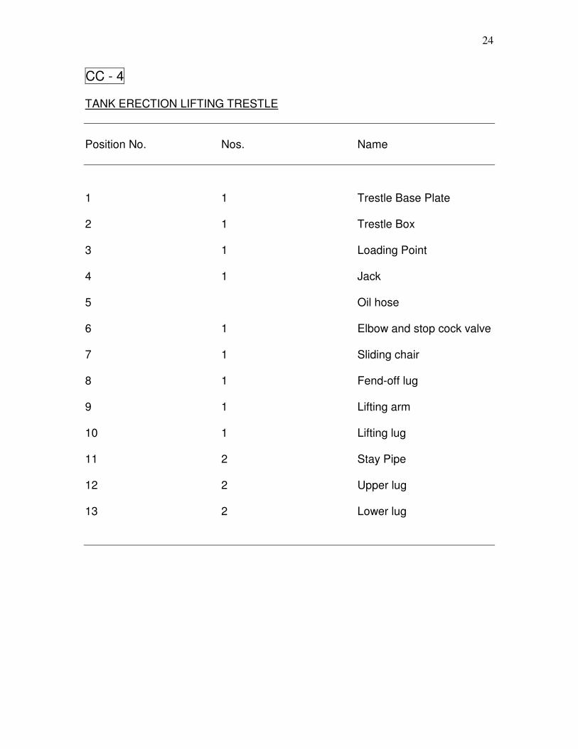
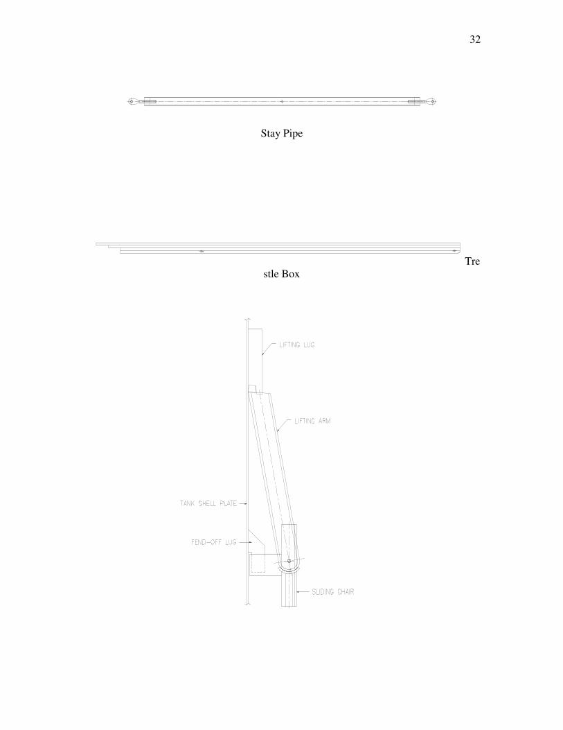
4.0 Description and components of the jacking equipment 4.1 The jacking equipment is composed of the following components (Drawing CC-3 and CC-4) 4.2 1 pc Trestle box with base plate Items 1 & 2 The trestle box is 3500 mm long 4.3 2 pcs Stay pipes with upper and lower lugs Items 11, 12 & 13
Stays with adjustable length. Average length is about 3180 mm. Trimming allowance is +/- 100 mm.
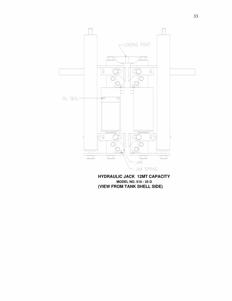
4.4 1 pc Loading point Item 3 Loading point is the point of transfer of load onto the jack from the trestle arm 4.5 1 pc hydraulic jack type 510-35D Item 4 4.6 High pressure oil hose Item 5 4.7 1 pc Stop cock valve with elbow Item 6 4.8 1 pc Sliding chair Item 7 Sliding chair with a seat for lifting arm and bracket for a fend-off lug 4.9 Lifting arm Item 9
6
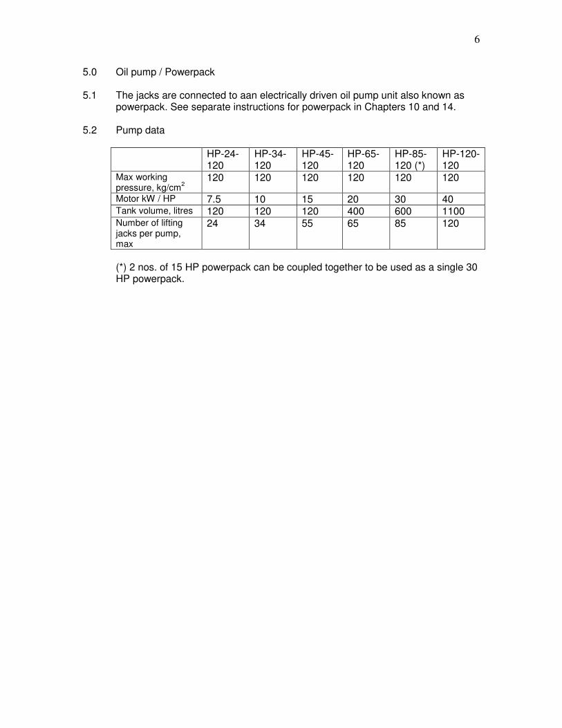
5.0 Oil pump / Powerpack 5.1 The jacks are connected to aan electrically driven oil pump unit also known as
powerpack. See separate instructions for powerpack in Chapters 10 and 14. 5.2 Pump data
HP-24-120
HP-34-120
HP-45-120
HP-65-120
HP-85-120 (*)
HP-120-120
Max working pressure, kg/cm
2
120 120 120 120 120 120
Motor kW / HP 7.5 10 15 20 30 40 Tank volume, litres 120 120 120 400 600 1100 Number of lifting jacks per pump, max
24 34 55 65 85 120
(*) 2 nos. of 15 HP powerpack can be coupled together to be used as a single 30 HP powerpack.
7
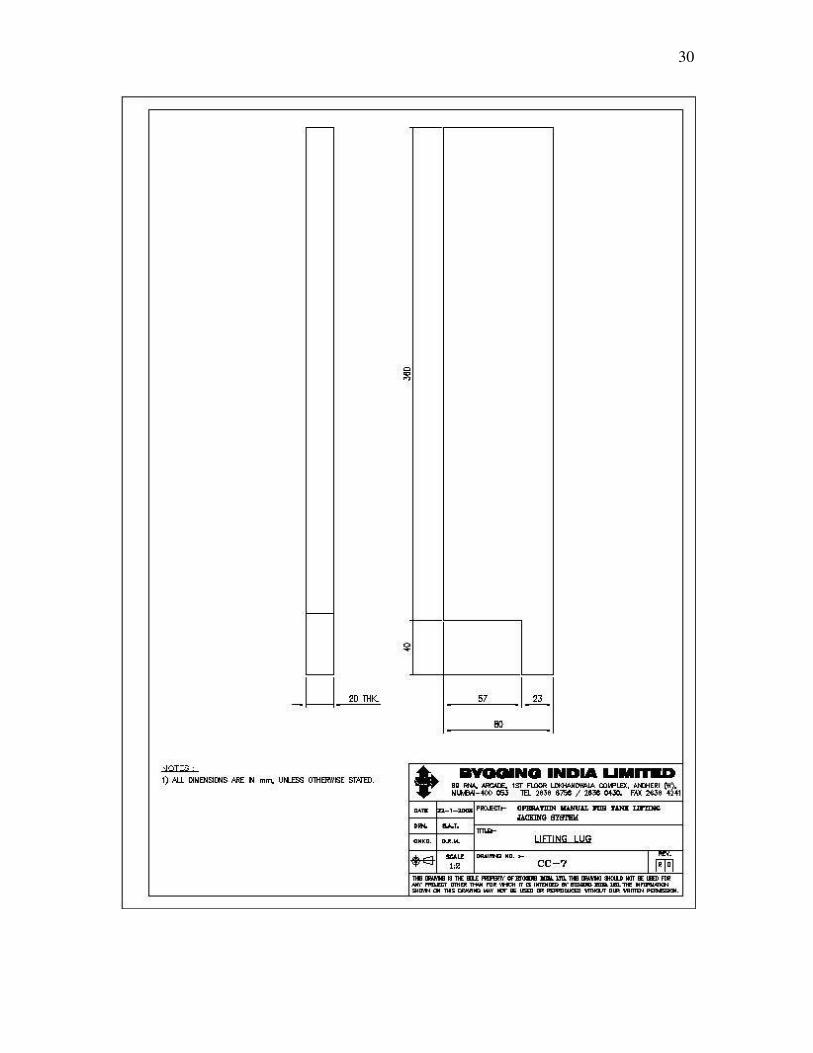
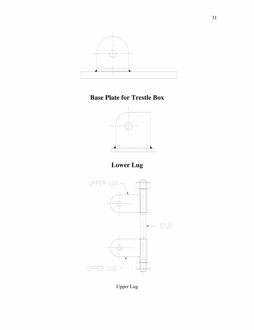
6.0 Auxiliary devices Drawing CC-3 to CC-7
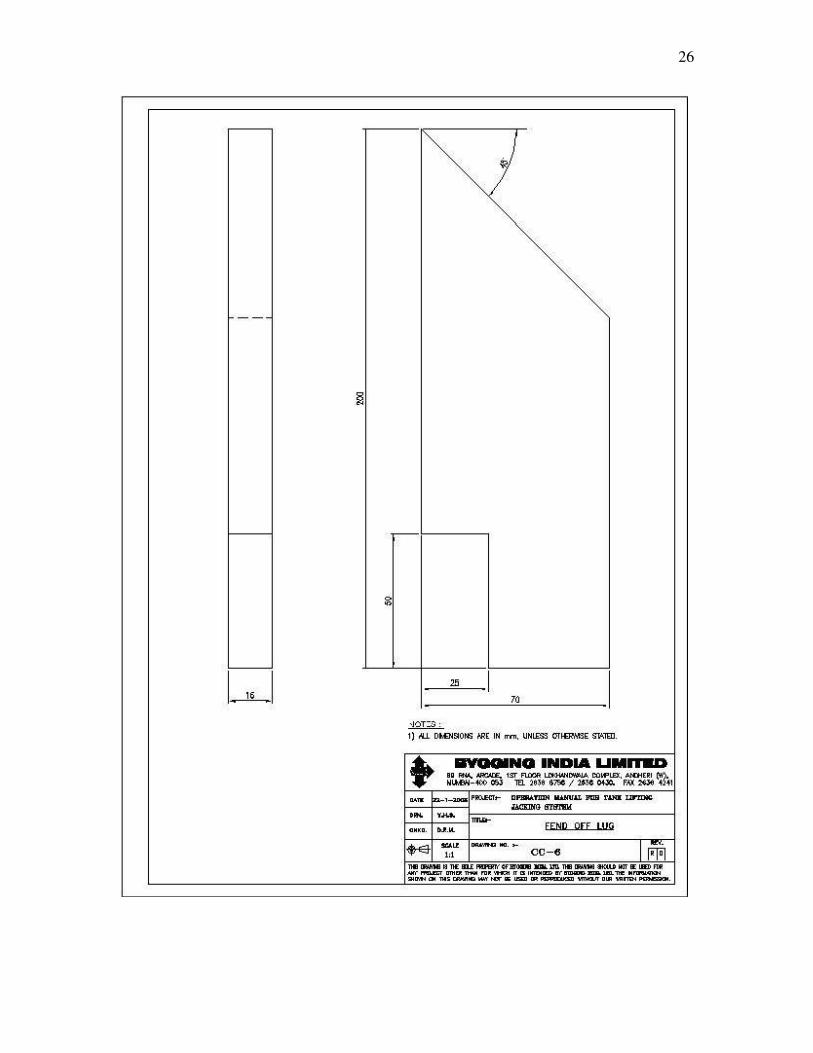
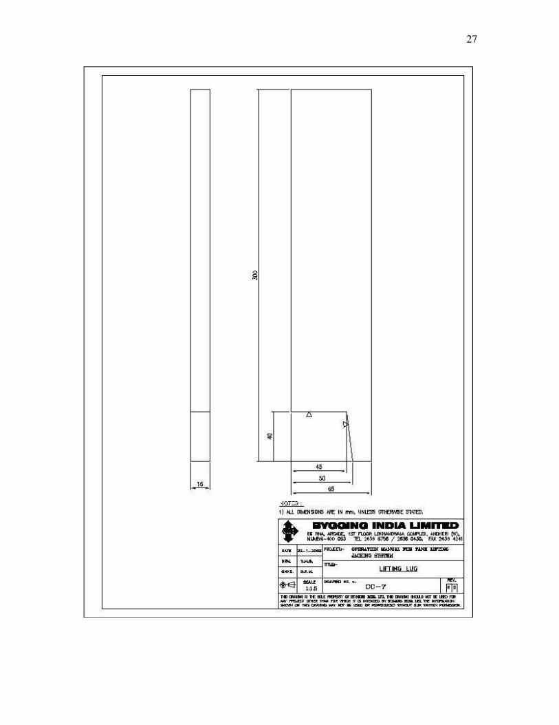
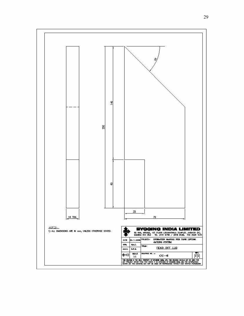
6.1 Fend-off lug (8) and lifting lug (10) are not included in the lifting equipment.
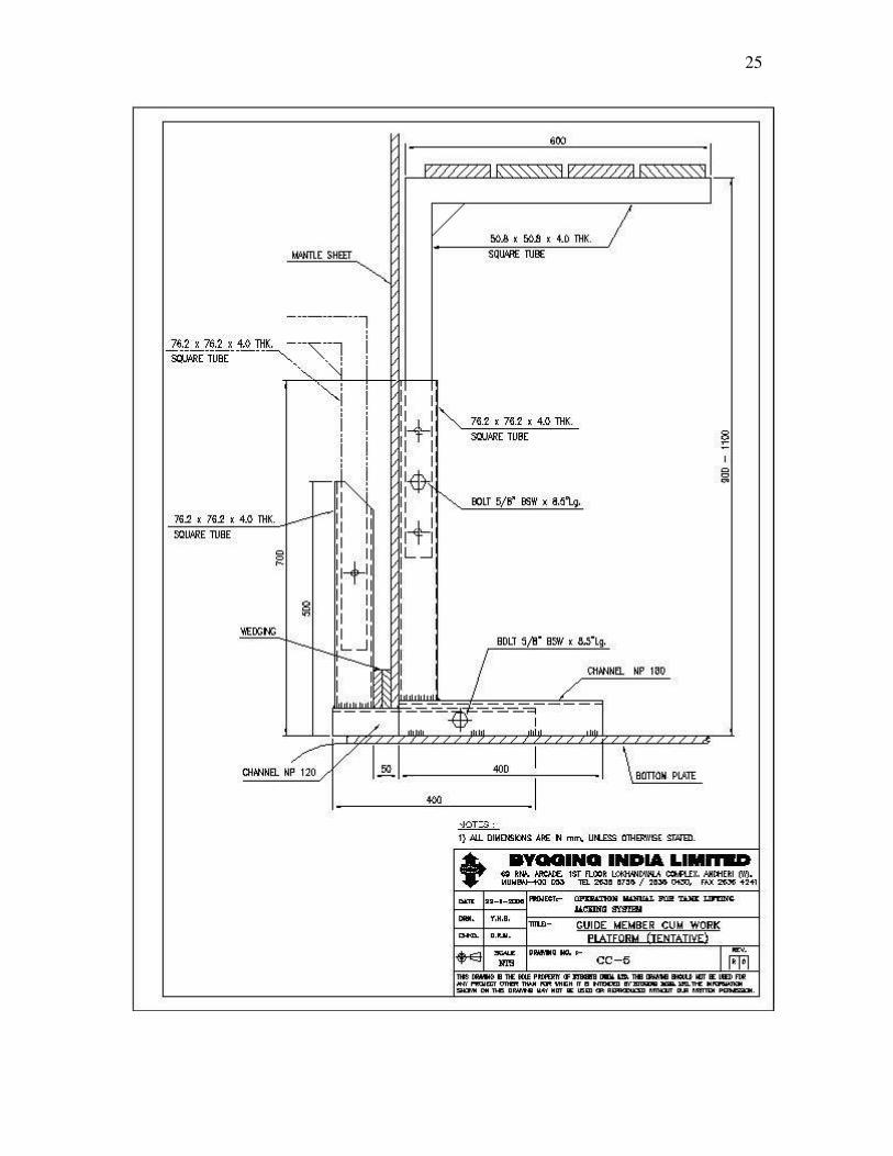
These details are made at site according to drawing CC-6 and CC-7 respectively. 6.2 As a guide when placing and adjusting the shell plates and as support during
welding, spacer cum guide beams are used. These beams can be provided with brackets for a gangboard.
8
7.0 Number of tank trestles 7.1 The number of trestle required for a tank is settled by:
a. The maximum weight of the tank. The vertical load is max 12 ton per trestle.
b. The maximum wind load on the trestles.
c. The maximum distance between the lifting points in the shell with regard
to the stability of shell.
The normal maximum distance between the trestles is 3 mtrs.
9
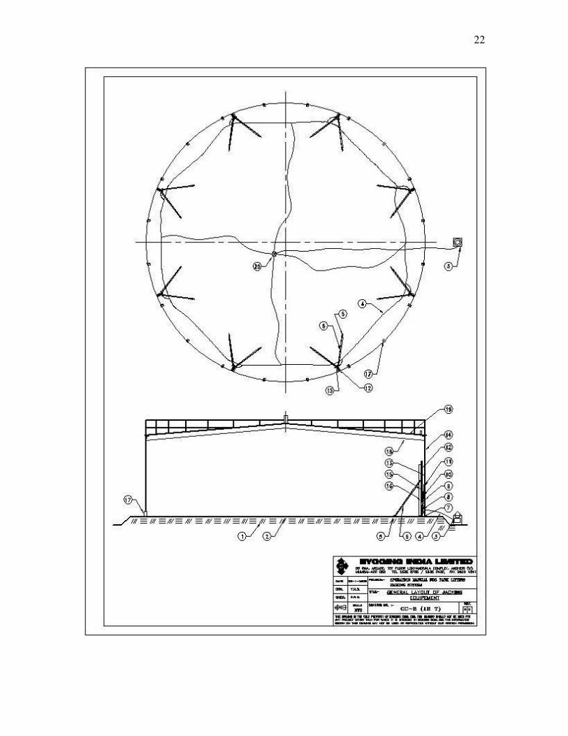
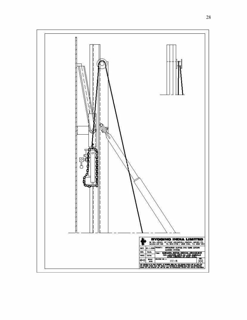
8.0 Example of tank under erection
The drawing CC-2 shows an example of a tank with arrangements necessary for the erection. The figures symbolize the following :
1. Foundation of the tank 2. Bottom plate 3. High pressure oil pump / powerpack 4. Oil line of high pressure hoses 5. Lower lug 6. Stay pipe 7. Base plate for trestle box 8. Hydraulic climbing jack 9. Fend-off lug 10. Lifting arm 11. Lifting lug 12. Jack rod of the lifting trestle 13. Next uppermost shell ring 14. Uppermost shell ring 15. Vertical column of lifting trestle / trestle box 16. Sliding chair 17. Spacer cum guide beam 18. Roof beam 19. Roof sheet 20. Manifold block
10
9.0 Working procedure 9.1 The tank periphery is marked out on the bottom plates 9.2 Spacers cum guide beams for guiding the sheets are placed at approx. 2 m
centres in between and are tack-welded to the bottom plates. 9.3 The first (uppermost) shell ring is positioned on the spacer cum guide beams.
The shell ring is checked to be exactly level. The shell plates are placed with correct radius and in plumb.
9.4 Roof beams are assembled and finally fastened to the uppermost shell ring.
Possibly some of the roof sheets are placed and welded. 9.5 The location of the lifting trestles is marked out inside the erected shell ring. The
division should be symmetrical with equal spacing between all tank trestles. 9.6 The lifting equipment is installed according to Chapters 10 and 13. 9.7 The first shell ring is lifted to a height at which the top edges of the tank trestles
are below the roof sheets. If the height of the two uppermost shell rings added together is less than the height of the trestle, these two shell rings should be welded together before this height is reached.
9.8 The roof sheets are placed and finally welded. 9.9 Raise the completed part of the tank so that the next shell ring can be inserted
below the first one.
Do not lift unnecessarily high ! The lifting can be stopped at any moment by putting the operating lever into the neutral position. The lift may not be exactly the same at all points. As soon as the required height is reached at one point, the lifting is stopped and the stop valve of that lifting point (jack) is closed. Then the lifting starts again until another point has reached the same height. This procedure is repeated until the correct height is reached at all the lifting points. All valves are thus now closed and the elevated part of the tank is now loading the lower grip-jaws of the climbing jacks.
9.10 Adjustment of the tank level can, if necessary, be made by lifting or lowering with
one or more jacks at a time, in doing which the valves on the other jacks should be closed.
9.11 The next shell ring is fitted and horizontally welded. For making the entrance to
the tank easier, the placing of the final sheet is left as long as possible. 9.12 The shell ring is finish welded on both sides. 9.13 The climbing jacks and sliding chairs are lowered one at a time using a rope with
chain (drwg CC-8). During this operation, both of the grip-jaw sets of the jacks must be in disengaged position.
11
9.14 The lifting and fend-off lugs (10 and 8 on drwg CC-3) are now welded to the next uppermost shell ring.
9.15 The same procedure as above is now repeated for following shell rings. As the
load on the lifting trestles has now increased, the oil pressure must be increased, but not more than necessary, and in no case more than 135 kg/cm2.
9.16 Before the assembly of the last (bottom) shell ring, all the spacers cum guide
beams are removed. If necessary the powerpack can be placed outside the tank. After the last shell ring is welded to the tank wall, the lower edge of the last shell ring is welded to the bottom plates.
9.17 The assembly and lifting equipment is dismantled. 9.18 Never make a lift in strong winds or when the wind velocity exceeds or is
expected to exceed the “maximum safe wind speed for lifting” which can be calculated by the manufacturer and provided on request.
12
10.0 Assembly of the jacking equipment and lifting Drawing CC-3
10.1 The trestle column (2) with climbing jack (4) and loading point (3), sliding chair
(7), stay pipes (11) and base plate (1) are placed radially along the tank periphery. The base plate is tack-welded to the tank bottom have a space measure of 125 mm between the inside of the shell sheet and the outside of the base-plate.
10.2 The vertical column of the lifting trestle is raised into vertical position. The two
lower lugs are welded to the tank bottom plate. The screws for vertical adjustment of the lifting trestle shall be screwed out about 100 mm in order to have adjustment. The vertical position is checked and adjusted in both directions, if required by rearranging the two stays.
10.3 All tank trestles are set up as described above. 10.4 The lifting and fend-off lugs (10, 8) are welded to the inside of the shell sheet.
Note, that there must be a space of about 5 to 10 mm between the upper edge of the spacing clamp of the sliding chair and the fend-off lug.
10.5 The elbows and stop cocks (6) are fitted to all jacks. 10.6 The powerpack is placed inside the tank or outside. Connect the powerpack with
hoses to the jacks. When using a large number of tank trestles make extra branch hose lines. See that the hoses are not twisted and hang them up for prevention of damage.
10.7 Test the oil pump. Check before starting that the motor is set for the existing
voltage. At delivery the motor is set for 380 / 415 V (as per customer requirement). Check the direction of rotation. Check the oil level. See separate pump instruction in Chapter 14.
10.8 Close all stop cocks of the climbing jacks and run the pump with 110 kg/cm2 oil
pressure to check the tightness of the hose joints. 10.9 Regulate the pump pressure to 50 – 60 kg/cm2 and stop the motor. Open all stop
cocks. The equipment is now ready for lifting. 10.10 Lifting.
Start the pump. Put the operating lever into lifting position and watch the pressure gauge and the jacks. If no lifting place at the set oil pressure, increase the pressure until lifting starts, but in no case should the pressure be increased to more than 120 kg/cm2. This operation must always be made with the lowermost pump pressure required as in that way even and uniform lifting occurs. When all the jacks have made their full stroke, the operating lever is slowly brought into return position. Keep in this position until all jacks have made their return stroke, that is the piston rods are completely retracted in the cylinders.
The operations are repeated until the required lifting height is reached.
13
11.0 Lifting speed 11.1 It is desirable that the lifting is made as quickly as possible. The oil must be fluid
at the existing temperature conditions. In cold weather a circulation run with preheated oil before starting the lifting operations can considerably shorten the return speed. The stroke volume is about 1.10 litres per climbing jack. The pumping time is calculated from the time the lever is pushed to start the lifting until the time the lever is brought back to neutral position. The pumping time is directly dependant on the pump capacity and the number of jacks connected, provided that the oil system is completely filled with oil and free of air.
14
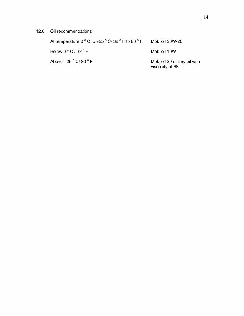
12.0 Oil recommendations
At temperature 0 o C to +25 o C/ 32 o F to 80 o F Mobiloil 20W-20
Below 0 o C / 32 o F Mobiloil 10W
Above +25 o C/ 80 o F Mobiloil 30 or any oil with viscocity of 68
15
13.0 Detailed instruction for installation and operation of jacking equipment
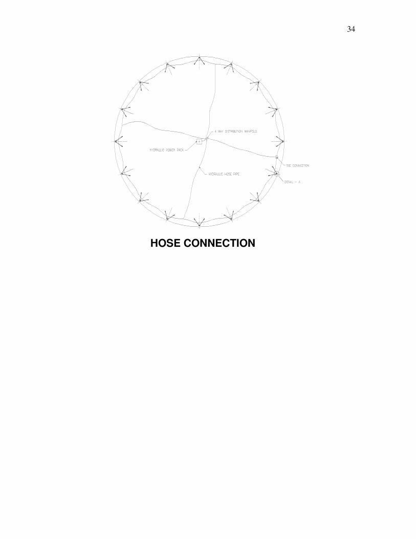
1. ERECTION OF JACKING EQUIPMENT A. FIXING OF TRESTLE BASE PLATE B. FIXING OF TRESTLE BOX AND STAY PIPES C. PLACING OF JACK AND FIXING OF LUGS D. HOSE CONNECTION
2. OPERATION OF HYDRAULIC JACKS
A. OPERATING THE JAW LOCKS FIXING OF TRESTLE BASE PLATE The trestle base plate of size 350 mm x 300 mm is to be fixed such that the centre of the base plate is at 275 mm from the inner face of the tank shell. All the base plates shall be placed at equal distance from each other around the periphery of the tank. The trestle base plate shall be fixed parallel to the tank shell plate such that the distance between the shell plate and trestle base plate is the same at both the edges of the base plate. The side measuring 350 mm shall be parallel to the tank shell plate. The base plate shall be welded to the tank bottom plate. FIXING OF TRESTLE BOX AND STAY PIPES The trestle box is laid horizontally on the tank foundation with the bottom bolt (6” long) in place and fixed to the trestle base plate. Two stay pipes are fixed to the trestle box with the stud bolt. The stay pipes are also laid on the ground horizontally. The loading point, sliding chair and lifting arm are fixed to the jack rod on the trestle box and slid to the end near the base plate. The complete assembly comprising of trestle box with 2 stay pipes are lifted up to vertical position. The jack rod should face the tank shell plate. For positioning of the lower lugs (base plate for the stay pipes), mark a point “X” on the tank bottom plate at about 2000 mm from the inner shell perpendicular to the trestle base plate. From this point mark two points perpendicular to the line joining the shell plate to the point “X”, at about 1200 mm distance on either side of point “X”. These two points are where the two lower lugs should be fixed and tack welded to the tank bottom plate. These distances are only indicative and may change depending upon the distance between the trestles. The angle forming between the two stays pipes should be between 60 degrees and 90 degrees. The trestle box should be proper plumb. This can be adjusted by rotating the stay pipes, which act like turn buckles. The tank shell plate is to be fixed on spacer cum guide beams of maximum 400 mm height (of appropriate section) placed at about 2000 mm centres around the periphery of the tank. This space of 400 mm allows for personnel to enter and exit from the tank when all the shell plates of a course / ring are fixed and welded. Before the trestle box and stay pipes are erected the following is to be ensured : At least two top most shell rings with a total height of more than the height of the trestle box (length of trestle box is 3500 mm for 2500 mm width plates and 4000 mm for 3000 mm width plates) should be erected and then roof constructed should be completed.
16
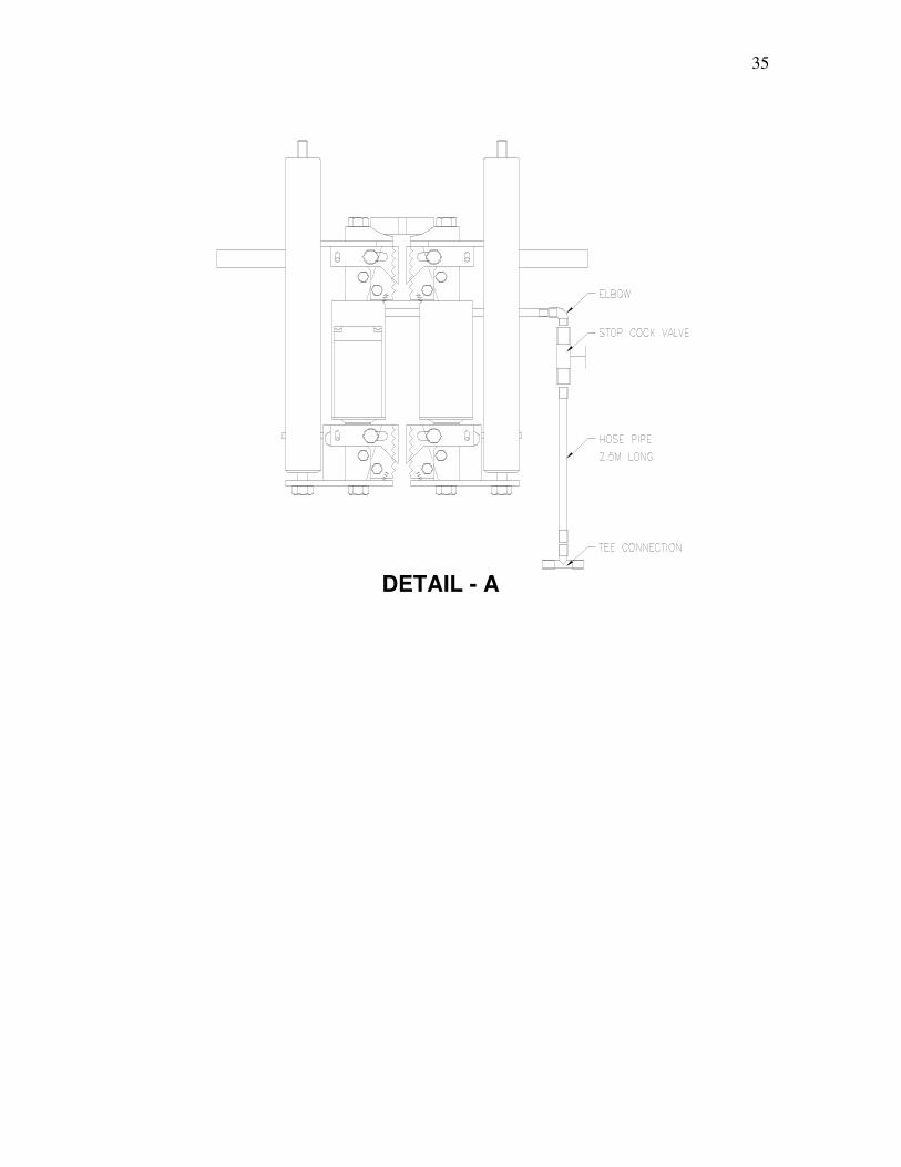
PLACING OF JACK AND FIXING OF LUGS The jack is to be mounted onto the jack rod of the trestle box below the loading point (by manually lifting the loading point, sliding chair and lifting arm) such that the loading point sits on the jack. All the four jaw lock levers should be on “locked” or “closed” position. Weld the lifting lugs at a level slightly above the point where the lifting arm touches the tank shell plate. All the lifting lugs should be at the same level. (This can be checked using water level tube). Normally 6 mm fillet weld on both sides along the full length of the lug is done and this weld quality is checked using suitable methods, such as DPT / MPI. The fend-off lugs are welded to the tank shell plate in such as manner that there is a gap of minimum 5 mm between the bottom edge of the fend off lug and the upper edge of the sliding chair, so as to ensure that no vertical load is transferred from the tank shell plate to the sliding chair. A special precaution to be taken only for 6 (or below) mm thick shell plates : Before welding the lifting lugs to the shell plates, patch plates of size 150 mm x 300 mm x 12 mm thick are welded to the 6 mm thick shell plates and the lifting lugs are welded to these 12 mm thick plates. (Fillet weld of 6 mm thick x 200 mm long on each vertical side of the patch plate and on each vertical side of the Lifting-lug) For the Fend-off lugs, patch plates of size 150 mm x 200 mm x 12 mm thick are welded to the 6 mm thick shell plates and the Fend-off lugs are welded to these 12 mm thick plates. In addition, a curved ring (with the same radius as the tank shell) fabricated of Mild steel angle or plate is to be placed on top of the lifting lug and stitch welded to the tank shell plate in case buckling is observed. After the hose and powerpack connection, lift all the jacks slightly so that the top of the lifting arm touches the bottom edge of the lifting lug. Now the jacking equipment is ready for lifting the tank. HOSE CONNECTION The Powerpack can be placed inside the tank or outside the tank. From the main outlet of the powerpack, one hose pipe is connected to the manifold block (5-way, 8-way or 10-way connector, depending upon the number of jacks used in the tank). From this manifold block, 4, 8 or 10 main distribution lines are fixed in radial direction. One hose of 2.5 mtrs is fixed to each jack through a stop cock valve. The other end of the hose is fixed to a Tee-connector, which in turn is fixed to other hoses forming a circumferential ring near the periphery of the tank. The main distribution hoses are connected to this circumferential ring using Tee-connections. Tafflon tape should be used at each hose joint. OPERATING THE JAW LOCKS There are four jaws in each jack, an upper pair and a lower pair. Each jaw can be locked or unlocked using jaw lock levers. By turning the levers on the left side in clockwise direction and the levers on the right side in the anti-clockwise direction, the levers can engage or lock the jaws. Always, both levers of either upper pair or lower pair should be operated simultaneously for locking and for unlocking. In the locked position, the jack
17
can only move upwards and not downwards. Therefore, during lifting, both the pairs of jaws should be in locked position. Only when the jack is to be lowered down, the levers are to be unlocked, but at any point of time, any one pair of jaws should be in locked position, otherwise the jack will fall down possibly causing injury.
18
14.0 OPERATING THE POWERPACK
The direction of rotation of fan should be clockwise (unless otherwise marked on the motor) when viewed from motor fan cover end. In case the direction of rotation is counter-clockwise, change any two phases.
Setting of pressure relief valve :
Fix a plug on the outlet Port and keep high-pressure ball valve closed. Start motor, wait until the motor switches from Star to Delta, then operate Direction control valve by pushing and holding back, adjust the pressure and set to 110 kg/cm2. Switch off the motor.
Remove plug from the port and connect to the 5-way, or 8-way manifold block using high pressure hose supplied with the system
Hose connection should be tight so that there is no leakage of oil. The oil tank should be filled with hydraulic oil of 68 grade (viscosity).
The motor is switched on. The lever of the high-pressure Ball valve should remain in closed position. Then the lever on the Direction control valve is pushed and held back in this position till the jacks achieve the full stroke length. The oil starts flowing out into the hose pipes and into the jacks. The jacks will lift the tank construction. After all the jacks have achieved the full stroke length of 100 mm (effectively 95 mm), the lever on the Direction Control valve is released and it comes back to neutral position by spring action. The high pressure ball valve is opened. This causes the protruded jack pistons to retract, thereby completing one lift cycle. This sequence of operations is repeated for each consecutive lift of 100 mm.
19
15.0 Maintenance and control instructions 15.1 All exposed parts should be cleaned regularly 15.2 Before each mounting of the climber the following must be checked :
a. The back of grip jaws are lubricated with grease between grip jaw back
and grip jaw head b. The teeth of the grip jaws are clean and the grip jaw backs are bright.
15.3 After 20 m of climbing, check the following :
a. That no grip jaws have become blunt b. That there is sufficient grease behind the grip jaws
15.4 The grip-jaw springs have not lost their tension 15.5 Powerpack should be covered properly to avoid entry of any foreign particles into
the powerpack components. 15.6 Filter of the powerpack should be changed periodically (after about every month
during continuous operation) 15.7 Hose pipe connections and couplings / tees / stop cock valves should be cleaned
with diesel oil before use. 15.8 Never leave the climbers with the pistons in protruded position. 15.9 Never leave the tank loaded onto the jacks for long periods of time.
20
16.0 Preventive maintenance for powerpack 16.1 A hydraulic system properly installed will serve for many years, provided that
routine maintenance is carried out and correct spare components are held to allow continuous operation during component overhaul.
16.2 Following are suggested measures for routine maintenance : a. Daily inspection : - check oil level - check for leakages - check for unusual noise and vibrations - correct operating sequence b. Monthly inspection - clean strainer - check oil condition and check for contamination of oil - check oil tank - replace return line filter element every six months 16.3 Cleanliness is of utmost importance. The hydraulic oil must never come in
contact with diluted soluble oils, chips, dust, etc. The filter cap must be closed immediately after filling oil into the tank.
16.4 The oil temperature must never exceed 65 to 70 degrees C, else there will be
faster oxidation of oil and oil change has to be made in shorter periods. Also, the oil seals will get damaged due to high temperature.
16.5 If foaming of oil is observed, the pump must be shut down and cause of oil
foaming should be determined and rectified. 16.6 The electric motor must never be started without having sufficient oil.
METHODOLOGY FOR REPAIRS / REPLACEMENTS OF TANK BOTTOM PLATES INLCUDING FOUNDATION (INCLUDING FOR FLOATING ROOF
TANKS)
1. The tank under maintenance is first gas freed, piping connections dismantled, checked and certified by the Engineer-in-charge.
2. If required, Fire screen, Safety Barrier is also erected around the tank.
3. For Floating roof tanks, the seal is dismantled and removed.
4. The rolling ladder to the roof is dismantled.
5. Considering safe load bearing capacity of the soil around the tank
periphery, structural members of heavy plates are placed around the tank periphery for erecting the vertical trestles. This is required for transferring the vertical load uniformly to the ground.
6. For supporting the stay pipes of the Trestles, Scaffolding arrangement
is made from the ground level to the tank foundation level around the tank foundation.
7. The roof drain is disconnected.
8. After erecting and aligning the vertical trestles and stay pipes the jacks
are mounted on the trestles.
9. Hydraulic circuit is completed.
10. The lifting lugs and fend-off lugs are welded to the tank shell.
11. The load of the tank is transferred to the jacking units by initial operation of the hydraulic pump.
12. The tank shell is separated from the bottom plates by gauging / cutting
the shell to bottom plate weld.
13. On completion of the cutting operation the entire load of the tank is transferred to the jacking units.
14. After checking, the hydraulic pump is operated and the tank shell and
roof is gradually lifted to the required height (maximum 2500 mm from the bottom plates).
15. The annular plates are cut and removed.
37
16. Before cutting the bottom plates, the pipe supports for the roof are removed after providing temporary supports at various locations.
17. To avoid continuous loading on the jacking units, the entire tank can be
lowered to temporary structurals / supports placed uniformly along the tank periphery.
18. The bottom plates are cut and removed in sequence.
19. After inspection, tank foundation is made ready in all respects
(including installation of cathodic protection system if required)
20. Newly fabricated annular plates are laid and welded and testing completed as per requirement.
21. The centerline of the tank periphery is marked.
22. The tank is lowered to the newly laid annular plates and aligned.
23. The bottom plates are laid and the welding and testing completed as
per code.
24. Shell to bottom welding is completed and testing as per codal requirement is completed.
25. The jacking units are dismantled.
26. The pipe supports for floating roof is placed at the required positions.
27. The rolling ladder, foam seal assembly, roof drain assembly is