1L1022465 • June 2010 • Rev A
OpenCircuitGearMEMBER OF THE SAUER-DANFOSS GROUP
™ TAP 60-200 Gear Pumps
Technical Information
Tap 60-200
Gear Pumps
Standard Flange
Parallel ShaftTapered Shaft Splined shaft
Installation dimensions
Specification Data
TypeCapacity cc/rev
Displacement at
1000 RPM litres/min.
Max
pressure bar
Max speed rev/min.
A BInlet Outlet
C D E c d e
TAP 60 - 200/60 60 280 3000 84 168 36 62 M10 30 56 M10
TAP 60 - 200/85 85 280 3000 89 178 36 62 M10 30 56 M10
TAP 60 - 200/106 106 235 2500 93 186 36 62 M10 30 56 M10
TAP 60 - 200/130 130 220 2500 97.5 195 45 72.5 M12 36 62 M10
TAP 60 - 200/148 148 210 2400 101 202 45 72.5 M12 36 62 M10
TAP 60 - 200/180 180 170 2400 107 214 56 92 M12 45 72.5 M12
TAP 60 - 200/200 200 150 2400 111 222 56 92 M12 45 72.5 M12
2L1022465 • June 2010 • Rev A
OpenCircuitGearMEMBER OF THE SAUER-DANFOSS GROUP
™ TAP 60-200 Gear Pumps
Technical Information
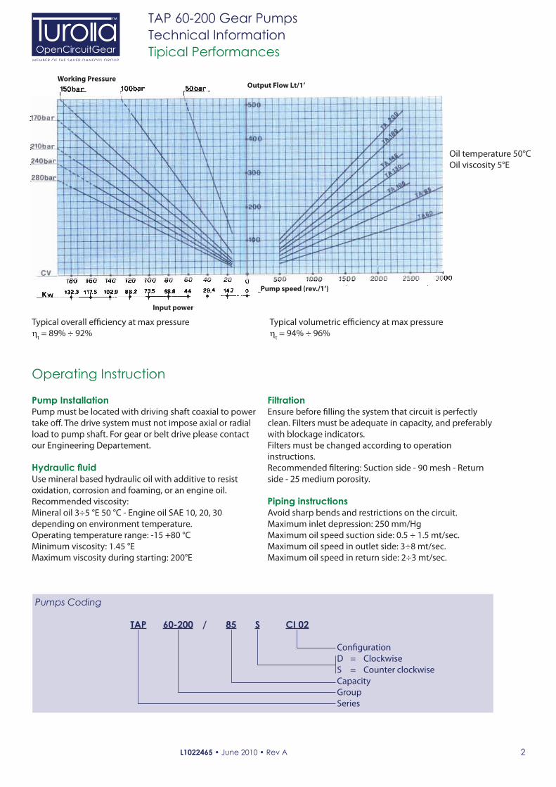
Tipical Performances
Pumps Coding
TAP 60-200 / 85 S CI 02
Con"guration
D = Clockwise
S = Counter clockwise
Capacity
Group
Series
Pump Installation
Pump must be located with driving shaft coaxial to power
take o#. The drive system must not impose axial or radial
load to pump shaft. For gear or belt drive please contact
our Engineering Departement.
Hydraulic fluid
Use mineral based hydraulic oil with additive to resist
oxidation, corrosion and foaming, or an engine oil.
Recommended viscosity:
Mineral oil 3÷5 °E 50 °C - Engine oil SAE 10, 20, 30
depending on environment temperature.
Operating temperature range: -15 +80 °C
Minimum viscosity: 1.45 °E
Maximum viscosity during starting: 200°E
Filtration
Ensure before "lling the system that circuit is perfectly
clean. Filters must be adequate in capacity, and preferably
with blockage indicators.
Filters must be changed according to operation
instructions.
Recommended "ltering: Suction side - 90 mesh - Return
side - 25 medium porosity.
Piping instructions
Avoid sharp bends and restrictions on the circuit.
Maximum inlet depression: 250 mm/Hg
Maximum oil speed suction side: 0.5 ÷ 1.5 mt/sec.
Maximum oil speed in outlet side: 3÷8 mt/sec.
Maximum oil speed in return side: 2÷3 mt/sec.
Operating Instruction
Typical volumetric e&ciency at max pressure
ηt = 94% ÷ 96%
Oil temperature 50°C
Oil viscosity 5°E
Typical overall e&ciency at max pressure
ηt = 89% ÷ 92%
Working PressureOutput Flow Lt/1’
Pump speed (rev./1’)
Input power
3L1022465 • June 2010 • Rev A
OpenCircuitGearMEMBER OF THE SAUER-DANFOSS GROUP
™ TAP 60-200 Gear Pumps
Technical Information
TAP 60-200
Gear Pumps
SAE C Flange
Parallel Shaft Splined shaft
Installation dimensions
Specification Data
TypeCapacity cc/rev
Displacement at
1000 RPM litres/min.
Max
pressure bar
Max
speed rev/min.
A BInlet Outlet
C D E F c d e f
TAP 60 - 200/60 60 280 30003.42
[87]
6.73
[171]1½
2.75
[69.8]
1.40
[35.7]
½ - 13
UNC - 2B1 ¼
2.31
[58.7]
1.18
[30.1]
7/16 - 14
UNC - 2B
TAP 60 - 200/85 85 280 30003.62
[92]
7.12
[181]1½
2.75
[69.8]
1.40
[35.7]
½ - 13
UNC - 2B1 ¼
2.31
[58.7]
1.18
[30.1]
7/16 - 14
UNC - 2B
TAP 60 - 200/106 106 235 25003.77
[96]
7.44
[189]2
3,06
[7.77]
1.68
[42.8]
½ - 13
UNC - 2B1½
2.75
[69.8]
1.40
[35,7]
½ - 13
UNC - 2B
TAP 60 - 200/130 130 220 25003.95
[100.5]
7.79
[198]2
3.06
[77.7]
1.68
[42.8]
½ - 13
UNC - 2B1½
2.75
[69.8]
1.40
[35.7]
½ - 13
UNC - 2B
TAB 60 - 200/148 148 210 24004.09
[104]
8.07
[205]2
3.06
[77.7]
1.68
[42.8]
½ - 13
UNC - 2B1½
2.75
[69.8]
1.40
[35.7]
½ - 13
UNC - 2B
TAB 60 - 200/180 180 170 24004.33
[110]
8.54
[217]2
3.06
[77.7]
1.68
[42.8]
½ - 13
UNC - 2B1½
2.75
[69.8]
1.40
[35.7]
½ - 13
UNC - 2B
TAB 60 - 200/200 200 150 24004.48
[114]
8.85
[225]2
3.06
[77.7]
1.68
[42.8]
½ - 13
UNC - 2B1½
2.75
[69.8]
1.40
[35.7]
½ - 13
UNC - 2B
4L1022465 • June 2010 • Rev A
OpenCircuitGearMEMBER OF THE SAUER-DANFOSS GROUP
™ TAP 60-200 Gear Pumps
Technical Information
Tipical Performance
Pumps Coding
TAP 60-200 / 85 S CI 02
Con"guration
D = Clockwise
S = Counter clockwise
Capacity
Group
Series
Pump Installation
Pump must be located with driving shaft coaxial to power
take o#. The drive system must not impose axial or radial
load to pump shaft. For gear or belt drive please contact
our Engineering Department.
Hydraulic fluid
Use a mineral based hydraulic oil with additive to resist
oxidation, corrosion and foaming, or an engine oil.
Recommended viscosity:
Mineral oil 3÷5 °E 50 °C - Engine oil SAE 10, 20, 30
depending on environment temperature.
Operating temperature range: -15 +80 °C
Minimum viscosity. 1.45 °E
Maximum viscosity during starting: 200 °E
Filtration
Ensure, before "lling the system, that circuit is perfectly
clean. Filters must be adequate in capacity and preferably
with blockage indicators.
Filters must be changed according to operating
instructions.
Recommended "ltering: Suction side - 90 mesh - Return
side - 25 medium porosity.
Piping instructions
Avoid sharp bends and restrictions on the circuit.
Maximum inlet depression: 250 mm/Hg
Maximum oil speed suction side: 0.5 ÷ 1.5 mt/sec.
Maximum oil speed in outlet side: 3÷8 mt/sec.
Maximum oil speed in return side: 2÷3 mt/sec.
Operating Instruction
Typical volumetric e&ciency at max pressure
ηt = 94% ÷ 96%
Oil temperature 50°C
Oil viscosity 5°E
Typical overall e&ciency at max pressure
ηt = 89% ÷ 92%
Working PressureOutput Flow Lt/1’
Pump speed (rev./1’)
Input power
5L1022465 • June 2010 • Rev A
OpenCircuitGearMEMBER OF THE SAUER-DANFOSS GROUP
™ TAP 60-200 Gear Pumps
Technical Information
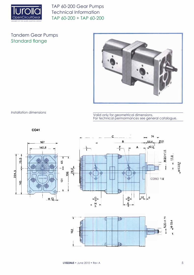
TAP 60-200 + TAP 60-200
Tandem Gear Pumps
Standard flange
Installation dimensionsValid only for geometrical dimensions. For technical permormances see general catalogue.
6L1022465 • June 2010 • Rev A
OpenCircuitGearMEMBER OF THE SAUER-DANFOSS GROUP
™ TAP 60-200 Gear Pumps
Technical Information
Specification Data
© 2010 Turolla OpenCircuitGear™. All rights reserved.
Turolla OCG accepts no responsibility for possible errors in catalogs, brochures and other printed material. Turolla OCG reserves
the right to alter its products without prior notice. This also applies to products already ordered provided that such alterations
can be made without affecting agreed specifications. All trademarks in this material are properties of their respective owners.
Sauer-Danfoss, Turolla, Turolla OpenCircuitGear, Turolla OCG, OpenCircuitGear, Fast Lane and PLUS+1 are trademarks of the
Sauer-Danfoss Group.
Specification Data
TypeTAP 60-200
+TAP 60-200
Capacity
cc/revDisplacement at
1000 RPM litres/min.
Max pressure bar Max
speedrev/min.
A B C
Inlet Outlet
First
pump
Second
pumpD E F G H L d e f g h l
60 + 60 60 + 60 280 280 3000 88 264 348 36 62 M10 36 62 M10 30 56 M10 30 56 M10
85 + 60 85 + 60 280 280 3000 93 274 358 36 62 M10 36 62 M10 30 56 M10 30 56 M10
85 + 85 85 + 85 250 250 3000 93 279 368 36 62 M10 36 62 M10 30 56 M10 30 56 M10
106 + 60 106 + 60 235 280 2500 97 282 366 36 62 M10 36 62 M10 30 56 M10 30 56 M10
106 + 85 106 + 85 200 245 2500 97 287 376 36 62 M10 36 62 M10 30 56 M10 30 56 M10
106 + 106 106 + 106 200 200 2500 97 291 384 36 62 M10 36 62 M10 30 56 M10 30 56 M10
130 + 60 130 + 60 205 260 2500 101.5 291 375 45 72.5 M12 36 62 M10 36 62 M10 30 56 M10
130 + 85 130 + 85 180 225 2500 101.5 296 385 45 72.5 M12 36 62 M10 36 62 M10 30 56 M10
130 + 106 130 + 106 175 185 2400 101.5 300 393 45 72.5 M12 36 62 M10 36 62 M10 30 56 M10
130 + 130 130 + 130 160 160 2400 101.5 304.5 402 45 72.5 M12 45 72.5 M12 36 62 M10 36 62 M10
148 + 60 148 + 60 185 250 2400 105 298 382 45 72.5 M12 36 62 M10 36 62 M10 30 56 M10
148 + 85 148 + 85 165 215 2400 105 303 392 45 72.5 M12 36 62 M10 36 62 M10 30 56 M10
148 + 106 148 + 106 160 175 2400 105 307 400 45 72.5 M12 36 62 M10 36 62 M10 30 56 M10
148 + 130 148 + 130 150 155 2400 105 311.5 409 45 72.5 M12 45 72.5 M12 36 62 M10 36 62 M10
148 + 148 148 + 148 140 140 2400 105 315 416 45 72.5 M12 45 72.5 M12 36 62 M10 36 62 M10
180 + 60 180 + 60 150 250 2400 111 310 394 56 90 M12 36 62 M10 45 72.5 M12 30 56 M10
180 + 85 180 + 85 135 215 2400 111 315 404 56 90 M12 36 62 M10 45 72.5 M12 30 56 M10
180 + 106 180 + 106 130 180 2400 111 319 412 56 90 M12 36 52 M10 45 72.5 M12 30 56 M10
180 + 130 180 + 130 120 160 2400 111 319 421 56 90 M12 45 72.5 M12 45 72.5 M12 36 62 M10
180 + 148 180 + 148 115 140 2400 111 327 428 56 90 M12 45 72.5 M12 45 72.5 M12 36 62 M10
180 + 180 180 + 180 115 115 2400 111 333 440 56 90 M12 56 90 M12 45 72.5 M12 45 72.5 M12
200 + 60 200 + 60 135 255 2400 115 318 402 56 90 M12 36 62 M10 45 72.5 M12 30 56 M10
200 + 85 200 + 85 120 220 2400 115 323 412 56 90 M12 36 62 M10 45 72.5 M12 30 56 M10
200 + 106 200 + 106 115 180 2400 115 327 420 56 90 M12 36 62 M10 45 72.5 M12 30 56 M10
200 + 130 200 + 130 110 160 2400 115 331.5 429 56 90 M12 45 72.5 M12 45 72.5 M12 36 62 M10
200 + 148 200 + 148 105 145 2400 115 335 436 56 90 M12 45 72.5 M12 45 72.5 M12 36 62 M10
200 + 180 200 + 180 105 115 2400 115 341 448 56 90 M12 56 90 M12 45 72.5 M12 45 72.5 M12
200 + 200 200 + 200 105 105 2400 115 345 456 56 90 M12 56 90 M12 45 72.5 M12 45 72.5 M12
Typical performance and operating instruction please apply to single pump lea*et
Fluids’ separation between two stages is not provided
Ordering Code
PFF 130 + 85 S CO41
Pump type Con"guration
D = Clockwise
S = Counter clockwise
Second pump capacity
First pump capacity


![HIT-HY 200 INJECTION MORTAR - Hilti Italy · HIT-HY 200 injection mortar Anchor design ... - Manual cleaning for borehole ... [mm] 50 60 60 96 100 -](https://static.documents.pub/doc/80x56/5ad347117f8b9a665f8d77c4/hit-hy-200-injection-mortar-hilti-italy-200-injection-mortar-anchor-design-.jpg)


