ARMY RESEARCH LABORATORY Design and Flight Test of a Prototype Range Control Module for an Wmm Mortar Michael S.L. Hollis Fred J. Brandon Peter C. Muller $xq: :,s$k, &g ARL-M R-463 SEPTEMBER 1999 19990917 011 Approved for public release; distribution is unlimited.
Transcript
ARMY RESEARCH LABORATORY
Design and Flight Test of a Prototype Range Control Module for an Wmm Mortar
Michael S.L. Hollis Fred J. Brandon Peter C. Muller
$xq: :,s$k, &g
ARL-M R-463 SEPTEMBER 1999
19990917 011
Approved for public release; distribution is unlimited.
The findings in this report are not to be construed as an offkial Department of the Army position unless so designated by other authorized documents.
Citation of manufacturer’s or trade names does not constitute an official endorsement or approval of the use thereof.
Destroy this report when it is no longer needed. Do not return it to the originator.
Army Research Laboratory Aberdeen Proving Ground, MD 2 1005-5066
ARL-MR-463 September 1999
Design and Flight Test of a Prototype Range Control Module for an 8 l-mm Mortar
Michael S.L. Hollis Fred J. Brandon Peter C. Muller Weapons and Materials Research Directorate
Approved for public release; distribution is unlimited.
i
Abstract
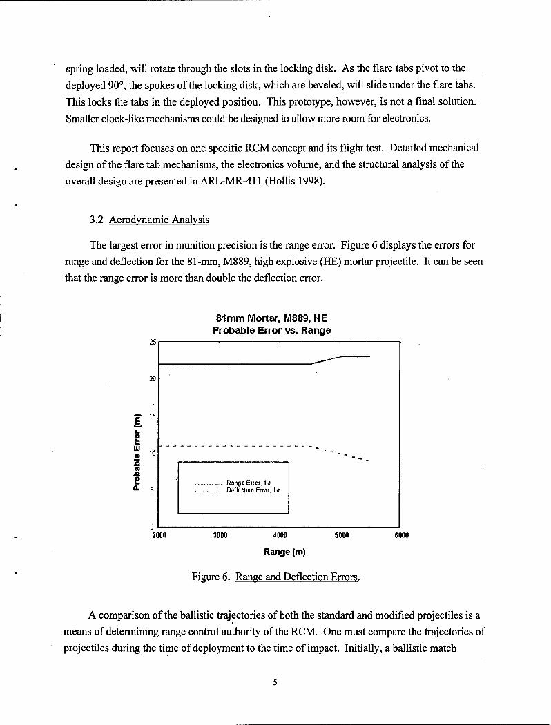
The primary purpose of the Light Forces Program is to improve the effectiveness of fire from the infantry mortar. Advances in microelectronics, sensors, and power supplies make it possible to design and build a miniature, one-dimensional, range correction module (RCM) for the mortar. This report focuses on the flight testing of an RCM prototype device for the 8 1 -mm mortar. The objective of testing the concept was to demonstrate the structural integrity and the drag authority of the design. Based on the experimental data, it can be seen that the undeployed range control modules do not affect the overall drag of the projectile. It can also be seen that when the RCM deploys, it has a significant effect on range. Experimental data obtained from the test indicate that the undeployed RCM does not change the ballistic characteristics of the shell; however, when deployed, the RCM does provide a significant method of controlling range.
*
\
ii
ACKNOWLEDGMENTS
l
The authors wish to express gratitude to those people who contributed to the success of
the program. The people of the Aberdeen Test Center, under the direction of Eric Rajkowski, are
to be recognized for conducting the firing test. In addition, those who aided in the design and
fabrication of the electrical and mechanical hardware are appreciated. Keith Dougherty and
William Pennington are to be praised for their expertise in fabricating the mechanical hardware.
Finally, Eugene Ferguson and Craig Myers are to be commended for their design work and
electrical fabrication.
. . . 111
.
.
INTENTIONALLY LEFT BLANK
L
iv
TABLE OF CONTENTS
1.
2.
3.
3.1 3.2
4.
5.
5.1 5.2 5.3
6.
LIST OF FIGURES ..........................................
Figure 12. Radial Velocities of First Control Round and RCM That DePloyed.
81mm Mortar, MB89 w/ ID Corrector Raw Radar Data
Radial Velocity vs. Time
11
dlmn Mortw.hl089 w/l0 Corrector Reduc+d Radar Data
Torrl Drag Coefliciwt n Em*
4, i I-- __--. -- --
Figure 13. Change in Drag for the RCM That Deployed.
5.3 Failure Analvsis
In an attempt to determine the cause of malfunction, the authors subjected the remaining
RCM unit to a series of tests. The device was first photographed with X-rays at various points
of view and intensities in an effort to ascertain anything peculiar. Since several electrical test
points were built into the RCM, electrical diagnostics were also performed. Everything was
verified, which led to placing the device in a fixture and subjecting it to an axial shock load equal
in magnitude to that of the set-back load for the M889El mortar projectile. The device had been
previously tested on the shock table with shock loads as high as 15,000 g’s for 0.0001 second.
However, the entire assembly, including g-hardened electronics, had not been shocked. With
electrical leads now attached to the test points, the RCM was shocked with approximately
12,000 g’s. Almost 15 seconds later, the flare tabs deployed. The resulting deployment of the
device left the cause for the three malfunctioning RCMs undetermined.
6. CONCLUSION
A design study and flight test demonstration were conducted to determine the range control
authority of a simple range control module. The module was designed to be added to a mortar shell
without requiring modifications of the components. The studies indicate that it would be possible
to mechanically change the drag at desired times during a flight to significantly shorten the normally
12
expected range. Based on predicted data and a detailed metal parts design, five RCM units were
built and flight tested. Of the four units that were fired, only one functioned as planned.
Although one successful deployment may not completely validate this experiment, it does
provide insight to the amount of range control that can be accomplished. The experimental drag
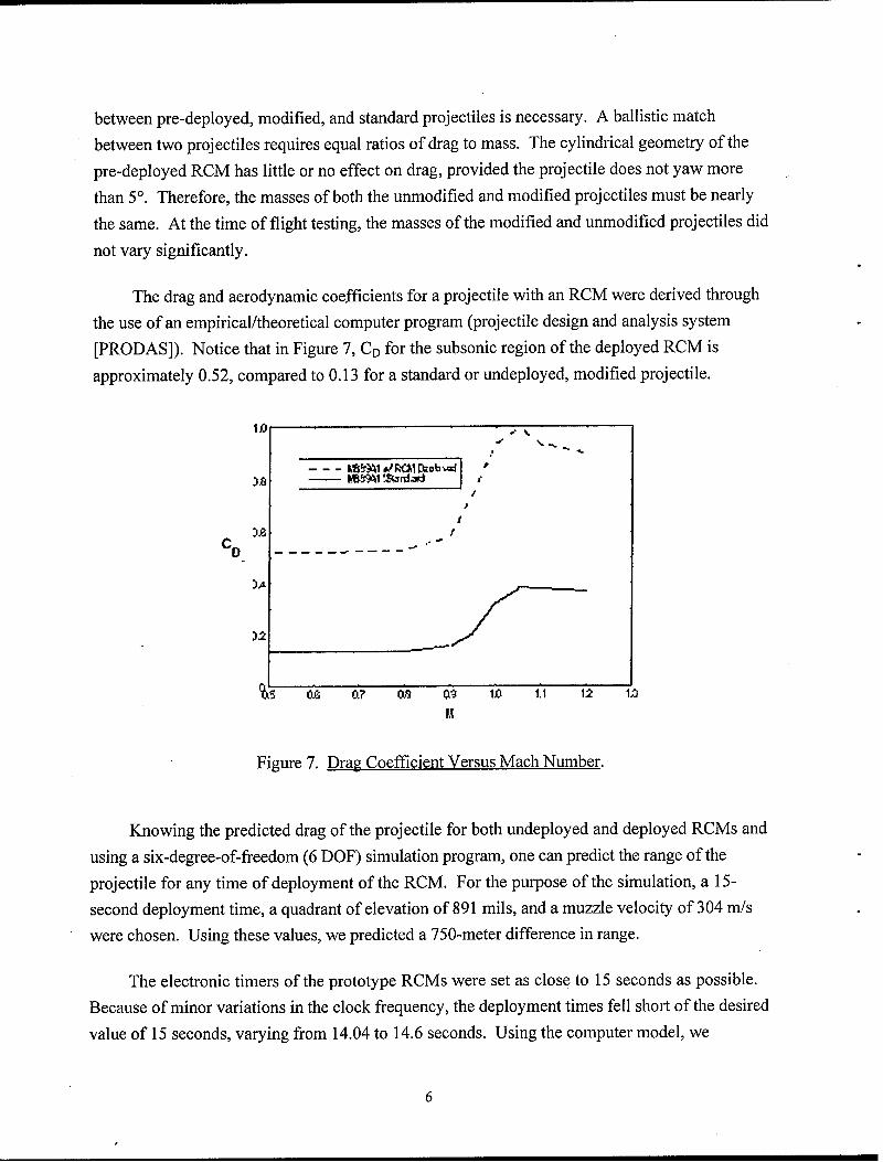
coefficient obtained from the one round of 0.48 (see Figure 13) is slightly less than the predicted
value of about 0.52 (see Figure 7). The mortar shell achieved an 850-meter reduction in range
when its RCM deployed at 13.8 seconds. Unfortunately, detailed examination of the unfired
RCM unit failed to provide any information as to why three of the flight units did not deploy.
Based on the design study and the test data obtained, it can be seen that the undeployed
range control modules with the mortar shell had very little effect on the overall drag of the
projectile. It can also be seen that when the RCM deploys, it will have a significant effect on
range, depending on the time of deployment.
.
.
13
.
.
INTENTIONALLY LEFT BLANK
14
REFERENCES
Condon, J.A., and M. Hollis, “Dynamic Analyses of the Mortar Dragster Tab Mechanism,” ARL-TN-107, U.S. Army Research Laboratory, Aberdeen Proving Ground, MD, April 1998.
D’Amico, W. “Low Cost Competent Munitions (LCCM) Self-Correction Devices-An Initial Study and Status,” ARL-TR-1178, U.S. Army Research Laboratory, Aberdeen Proving Ground, MD, August 1996.
Hollis, M. “Preliminary Design of a Range Correction Module for an Artillery Shell,” ARL-MR- 298, U.S. Army Research Laboratory, Aberdeen Proving Ground, MD, March 1996.
Hollis, M. “Design and Analysis of a Prototype Range Correction Device for a Mortar Projectile,” ARL-MR-411, U.S. Army Research Laboratory, Aberdeen Proving Ground, MD, August 1998.
US TACOM-ARDEC, “Firing Tables for Mortar, 81-mm, M252,” FT 81-AR-2, Firing Tables and Aeroballistic Branch, June 1997.
Raj kowski, Eric. “Test Record,” Test Record No. LS-00208, TECOM Project No. 2-MU-OOl- RCD-001, U.S. Army Aberdeen Test Center, Aberdeen Proving Ground, MD, August 1998.
I *
15
.
,
INTENTIONALLY LEFT BLANK
.
.
16
.
.
NO. OF COPIES
2
1
1
1
4
2
1
” 15
ORGANIZATION
ADMINISTRATOR DEFENSE TECHNICAL INFO CENTER ATTN DTIC OCP 8725 JOHN J KINGMAN RD STE 0944 FT BELVOIR VA 22060-62 18
DIRECTOR US ARMY RESEARCH LABORATORY ATTN AMSRL CS AS REC MGMT 2800 POWDER MILL RD ADELPHI MD 20783- 1197
DIRECTOR US ARMY RESEARCH LABORATORY ATTN AMSRL CI LL TECH LIB 2800 POWDER MILL RD ADELPHI MD 207830-l 197
DIRECTOR US ARMY RESEARCH LABORATORY ATTN AMSRL DD J J ROCCHIO 2800 POWDER MILL RD ADELPHI MD 20783- 1197
DIRECTOR US ARMY RSRCH LAB ATTN AMSRL SS SM J EIKE
J GERBER A LADAS G WILES 2800 POWDER MILL RD ADELPHI MD 20783-l 145
DIR US ARMY CECOM ATTN AMSEL RD C2 CS
DR J VIG DR R FILLER FT MONMOUTH NJ 07703-560 1
COMMANDER US ARMY RSRCH OFC ATTN AMXRO RT IP TECH LIB PO BOX 122 11 RSCH TRIANGLE PARK NC 27709-22 11
CMDR US ARMY ARDEC ATTN AMSTA AR AET A M AMORUSO
EBROWN CCHUNG AFARINA JGRAU SKAHN KKENDL C LIVECCHIA C NG G MALEJKO W TOLEDO B WONG J THOMASOVICH
AMSTA AR AET C S LONG0 AMSTA AR FZ L SPRINGER
PICATINNY ARSENAL NJ 07806-5000
NO. OF COPIES ORGANIZATION
CMDR US ARMY ARDEC AT-I-N AMSTA FSP A S DEFAO
N GRAY V ILLARDI S SARULLO R SICIGNANO D COLLET R WERKO
PICATINNY ARSENAL NJ 07806-5000
COMMANDER USA DUGWAY PROV GRND ATTN TECH LIB DUGWAY UT W22
COMMANDER USA YUMA PROV GRND ATTN STEYT MT EA C HASTON YUMA AZ 85365-9110
COMMANDER USA YUMA PROV GRND ATTN STEPY RS EL A HOOPER YUMA AZ 85365-9110
COMMANDER US ARMY MISSILE COMMAND ATTN AMSMI RD W WALKER REDSTONE ARSENAL AL 35898-5000
DIRECTOR US ARMY RTTC ATTN STERT TE F TD R EPPS
K WHIGHAM BLDG 7855 REDSTONE ARSENAL AL 35898-8052
COMMANDER NAVAL SURFACE WARFARE CTR ATTN TECH LIB
D HAGEN J FRAYSEE 17320 DAHLGREN RD DAHLGREN VA 22448-5 150
COMMANDER NAWC WPN DIV TT&I SYS DPT ATTN CODE 3904 D SCOFIELD
CODE 543400D S MEYER CODE 54AOOOD S GATTIS
1 ADMINISTRATION CIRCLE CHINA LAKE CA 93555-6100
OFFICER IN CHARGE NAVAL EOD FACILITY ATTN TECH LIB INDIAN HEAD MD 20640
17
NO. OF COPIES
1
ORGANIZATION
ROCKWELL INTL CORP AUTONETICS ELECTR SYS DIV ATTN R CHRISTIANSEN 3370 MIRALOMA AVE PO BOX 3 105 ANAHEIM CA 92803-3 105
CHLS STARK DRAPER LAB INC ATTN J ELWELL J SITOMER 555 TECHNOLOGY SQUARE CAMBRIDGE MA 02139-3563
INTERSTATE ELECTR CORP ATT-N J GRACE 1001 E BALL RD ’ ANAHEIM CA 92803
INTERSTATE ELECTR CORP ATTN I REIDER 1735 JEFFERSON DAVIS HWY STE 905 ARLINGTON VA 22202
DYNAMIC SCIENCE INC ATTN S ZARDAS P NEUMAN PO BOX N ABERDEEN MD 2 100 1
ARROW TECH ASSOCIATES INC ATTN W HATHAWAY
JOHN WHYTE R WHYTE 1233 SHELBOURNE RD STE D8 SOUTH BURLINGTON VT 05403
PICO SYSTEMS INC ELECTRONIC PKG & TECH DEPT ATTN J BANKER PO BOX 134001 ANN ARBOR MI 48113-4001
ROCKWELL INTNLCORP COMM DIV ATTN D DEALE 350 COLLINS RD NE CEDAR RAPIDS IA 52498
CDR US ARMY INFANTRY CENTER ATTN ATZB CDF LTC DOUG LITAVEC FT BENNING GA 3 1905-5800
CDR US ARMY INFANTRY CENTER ATTN ATZB WC CHRIS KEARNS FT BENNING GA 3 1905-5400
NO. OF COPIES
1
4
1
1
1
2
1
1
1
3
I
ORGANIZATION
CG TACOM ARDEC MCLO ATTN MAJ MURRAY BLDG 1 PICATINNY ARSENAL NJ 07806-5000
CDR US ARMY ARDEC ATTN AMSTA AR DSA MO ED LEWIS
P BURKE A WOOD P FELTH PICATINNY ARSENAL NJ 07806-5000
.
CDR US ARMY ARDEC ’ ATTN AMSTA AR FSA M RANDY HAND
PICATINNY ARSENAL NJ 07806-5000
CDR US ARMY ARDEC ATT-N AMSTA AR FSA D BOB WORTH PICATINNY ARSENAL NJ 07806-5000
CDR US ARMY ARDEC ATTN AMSTA AR FSP G
DAVE PANHORST PICATINNY ARSENAL NJ 07806-5000
CDR US ARMY ARDEC ATTN AMSTA AR FSP Z MATT CILLI
MIKE ENNIS PICATINNY ARSENAL NJ 07806-5000
CDR USMC MARCORSYSCOM ATTN MAJ BRUCE MARTIN QUANTICO VA 22 134
TAP/AIRCRAFT INSTRUMENTATION DIV ATTN R FAULSTICH 5.4.2 UNIT 1 47765 RANCH ROAD NAVAL AIR WARFARE CTR AIRCRAFT DIVISION PATUXENT RIVER MD 20670- 1469
DIR RSCH & LABORATORY MGMT DEPUTY ASST SECY (RES & TECH) ATTN SARD TR RICK MORRISON 25 11 JEFFERSON DAVIS HWY SUITE 9000 ARLINGTON VA 22202-3911 .
CMDR US ARMY ARDEC ATT-N ADAWS ARDEC M MATTICE
D CARLUCCI .
MCATD ARDEC NIGEL GRAY PICATINNY ARSENAL NJ 07806-5000
ANALOG DEVICES ATTN ROBERT MEISENHELDER 804 WOBURN ST WILMINGTON MA 0 1887-3462
18
.
NO. OF COPIES
1
ORGANIZATION
MCC ATTN ROBERT MIRACKI 3500 w BAL~ONE~ CENTER AUSTIN TX 78759-5398
DAVID PAREKH 7220 RICHARDSON RD SMYRNA GA 30080
STRICOM ATT-N AMSTI LL M PHILLIPS
STRICOM EL D SCHNEIDER RONALD COLANGELO
12350 RESEARCH PARK ORLANDO FL 32826-3276
US ARMY RESEARCH LABORATORY ATTN AMSRL SE RL B PIEKARSKI ADELPHI MD 20783- 1197
DARPA ATTN ALBERT PISANO 3701 N FAIRFAX DRIVE ARLINGTON VA 22203- 1714
SRS TECHNOLOGIES ATTN JACK SUDDRETH 3900 FAIRFAX DRIVE ARLINGTON VA 22203
NAWC/WPNS ATTN CODE 543200E D POWELL
GARY BQRGEN BLDG 311 POINT MUGU CA 93042-5000
KDI PRECISION PRODUCTS ATTN MAX CONE
WILLIAM KURTZ 3975 MCMANN ROAD CINCINATTI OH 45245-2395
APL ATTN RON DENISSEN
WM DEVEREUX R BENSON H CHARLES JR
11100 JOHNS HOPKINS ROAD LAUREL MD 20723-6099
AR0 ATTN THOMAS DOLIGALSKI POB 12211 RSCH TRIANGLE PK NC 27709
NO. OF COPIES
1
ORGANIZATION
JOHN EBERSOLE CREATIVE OPTICS 360 STATE ROUTE 101 BEDFORD NH 03 1 lo-503 1
DRAPER LABORATORY ATTN JOHN ELWELL 555 TECHNOLOGY SQUARE CAMBRIDGE MA 02139
IOA INST FOR DEFENSE ANALYSIS ATTN JOHN FRASIER
RICHARD SINGER 1801 N BEAUREGARD ST ALEXANDRIA VA 2231 l-1772
NSWC/IHDIV ATTN CODE 40D D GARVICK 101 STRAUSS AVE INDIAN HEAD MD 20640-5035
TEXAS INSTRUMENTS ATTN TOMMY HICKS 8816 CROSSWIND DRIVE FORT WORTH TX 767 19
PAUL ZEMANY LOCKHEED-SANDERS 25 CANAL ST NASHUA NH 0306 l-0868
ABERDEEN PROVING GROUND
DIRECTOR US ARMY RESEARCH LABORATORY ATTN AMSRL CI LP (TECH LIB) BLDG 305 APG AA
NO. OF ORGANIZATION COPIES
2
1
15
US ARMY ATC ATTN STEAC TC E K MCMULLEN
STEAC TE H CUNNINGHAM BLDG 400
DIR USARL ATTN AMSRL WM B A W HORST JR BLDG 4600
DIR USARL ATTN AMSRL WM BA F BRANDON
T BROWN L BURKE J CONDON W D’AMICO B DAVIS T HARKINS D HEPNER M HOLLIS (5 CYS)’ V LEITZKE A THOMPSON
BLDG 4600
DIR USARL ATTN AMSRL WM BB H ROGERS
R VON WAHLDE BLDG 1121
DIR USARL ATTN AMSRL WM BB T VONG BLDG 1120A
DIR USARL ATTN AMSRL WM BC B GUIDOS
P PLOSTINS D LYONS S WILKERSON
BLDG 390
DIR USARL ATTN AMSRL WM BD B FORCH BLDG 4600
DIR USARL ATTN AMSRL WB BF
J LACETERA BLDG 120
DIR USARL ATT-N AMSRL WM BR
C SHOEMAKER BLDG 1121
DIR USARL ATTN AMSRL WM MB
B BURNS L BURTON BLDG 4600
20
t
NO. OF ORGANIZATION COPIES?
1 DIRECTOR US ARMY RESEARCH LABORATORY ATTN AMSRL. CS EA TP TECH PUB BR 2800 POWDER MILL RD ADELPHI MD 20783-l 197
21
INTENTIONALLY LEFT BLANK
22
REPORT DOCUMENTATION PAGE Form Approved OMB No. 0704-0188
Public reporting burden for this collection of information is estimated to average 1 hour per response, in&din the time for reviewing instructions, searching existing data sources, gathering and maintaining the data needed, and completing and reviewing the collection of infomtatron. Sen comments re ardrng this burden estimate or any other aspect of this
dg ? collection of information, mcluding suggestions for reducing this burden, to Washington Headquarters Services, Directorate or information Operations and Reports, 1215 Jefferson Davis Highway, Suite 1204, Arlington, VA 22202-4302, and to the Office of Management and Budget, Paperwork Reduction Project (0704-0188), Washington, DC 20503.
1. AGENCY USE ONLY (Leave blank) 2. REPORT DATE 3. REPORT TYPE AND DATES COVERED
September 1999 Final
4. TITLE AND SUBTITLE 5. FUNDING NUMBERS
Design and Flight Test of a Prototype Range Control Module for an 81-mm Mortar PR: lL162618AHSO
9. AUTHOR(S)
Hollis, M.S.L.; Brandon, F.J.; Muller, P.C. (all of ARL)
7. PERFORMING ORGANIZATION NAME(S) AND ADDRESS 8. PERFORMING ORGANIZATION REPORT NUMBER
U.S. Army Research Laboratory Weapons & Materials Research Directorate Aberdeen Proving Ground, MD 2 10 1 O-5066
3. SPONSORING/MONITORING AGENCY NAME(S) AND ADDRESS 10. SPONSORING/MONITORING
U.S. Army Research Laboratory AGENCY REPORT NUMBER
!2a. DISTRIBUTION/AVAILABILITY STATEMENT 12b. DISTRIBUTION CODE
Approved for public release; distribution is unlimited.
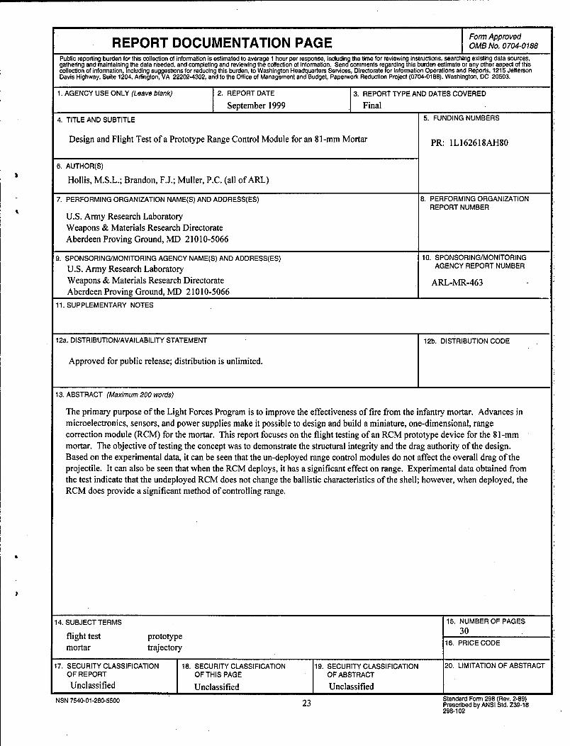
3. ABSTRACT (Maximum 200 words)
The primary purpose of the Light Forces Program is to improve the effectiveness of fire from the infantry mortar. Advances in microelectronics, sensors, and power supplies make it possible to design and build a miniature, one-dimensional, range
correction module (RCM) for the mortar. This report focuses on the flight testing of an RCM prototype device for the 8 1 -mm mortar. The objective of testing the concept was to demonstrate the structural integrity and the drag authority of the design. Based on the experimental data, it can be seen that the un-deployed range control modules do not affect the overall drag of the projectile. It can also be seen that when the RCM deploys, it has a significant effect on range. Experimental data obtained from the test indicate that the undeployed RCM does not change the ballistic characteristics of the shell; however, when deployed, the RCM does provide a significant method of controlling range.
4. SUBJECT TERMS 15. NUMBER OF PAGES
flight test prototype 30
mortar trajectory 16. PRICE CODE
7. SECURITY CLASSIFICATION 18. SECURITY CLASSIFICATION 19. SECURITY CLASSIFICATION 20. LIMITATION OF ABSTRACT OF REPORT OF THIS PAGE OF ABSTRACT
Unclassified Unclassified Unclassified
NSN 7540-01-280-5500 23 Standard Form 298 (Rev. 2-89) Prescribed by ANSI Std. 239-18 298-i 02