ACID AirCraft ID ARTCC Air Route Traffic Control Center ARTS Automated Radar Terminal System ATA Air Traffic Assistant ATC Air Traffic Control DESIREE The Distributed Environment for SImulation, Rapid
Engineering, and Experimentation. DIS Distributed Interactive Simulation DRAT Data Reduction Analysis Tool DTD Data Table Definition ECO Exercise Control Operator ERCE E Radio Control Equipment FP Flight Plan GUI Graphical User Interface HFL Human Factors Laboratory LRR Long Range Radar NAS National Air Space RBX Radar BoX Rx Receiver RDHFK Research and Development Human Factors Laboratory SAR System Analysis Recording SPW SimPilot Workstation TGF Target Generation Facility TMU Traffic Management Unit UFP Universal Flight Plan VM Virtual Machine XML eXtensible Markup Language XSD XML Schema Definition XPVD X-Version Planned View Display Wx Weather
TGF 9/30/2003 iv
Table of Figures Figure 1 Initial Exercise Control Operator...................................................................................................................2 Figure 2 .........................................................................................................................................................................3 Figure 3 Simulation Options .........................................................................................................................................4 Figure 4 Completely Filled Exercise Control Operator................................................................................................5 Figure 5 Initial Exercise Control Operator...................................................................................................................9 Figure 6 Exercise Control Operator ...........................................................................................................................10 Figure 7 Custom Menu Selections ...............................................................................................................................11 Figure 8 Scenario ........................................................................................................................................................12 Figure 9 Scenario Text Editor .....................................................................................................................................12 Figure 10 Flights .........................................................................................................................................................13 Figure 11 Flights Text Editor ......................................................................................................................................13 Figure 12 Universal Flight Plan Editor ......................................................................................................................14 Figure 13 Event Files ..................................................................................................................................................15 Figure 14 Event Files Text Editor ...............................................................................................................................15 Figure 15 Audio Files..................................................................................................................................................16 Figure 16 Audio Files Text Editor...............................................................................................................................16 Figure 17 Speed and Complexity.................................................................................................................................18 Figure 18 Misc. ECO Control Buttons ........................................................................................................................19 Figure 19 Empty Sim Pilot Workstations ....................................................................................................................20 Figure 20 Select Simpilot Controls..............................................................................................................................21 Figure 21 Simpilot Workstations .................................................................................................................................22 Figure 22 Bottom Portion of Simpilot Workstation.....................................................................................................22 Figure 23 Selected Sim Pilot Workstations .................................................................................................................23 Figure 24 Sim Pilot Workstations Being Opened ........................................................................................................24 Figure 25 Sim Pilot Workstations Ready.....................................................................................................................24 Figure 26 Radars.........................................................................................................................................................25 Figure 27 Rbx Control.................................................................................................................................................25 Figure 28 Rbx Control.................................................................................................................................................26 Figure 29 One Rbx Control .........................................................................................................................................27 Figure 30 Available Rbx Devices ................................................................................................................................27 Figure 31 Selected Rbx Device....................................................................................................................................28 Figure 32 Selected Rbx Control ..................................................................................................................................28 Figure 33 Miscellaneous Rbx Control Buttons............................................................................................................29 Figure 34 Interfacility Rbx Control .............................................................................................................................30 Figure 35 Loading the Scenario ..................................................................................................................................31 Figure 36 Waiting for Scenario to Load......................................................................................................................31 Figure 37 Simulation Output .......................................................................................................................................31 Figure 38 Exercise Ready............................................................................................................................................32 Figure 39 Exec Xpvd ...................................................................................................................................................32 Figure 40 Xpvd ............................................................................................................................................................33 Figure 41 Miscellaneous Simulation Control Buttons.................................................................................................34 Figure 42 ECO Custom Menu .....................................................................................................................................35 Figure 43 Drat Options ...............................................................................................................................................37 Figure 44 HFL Enroute summary ...............................................................................................................................37 Figure 45 Drat Simpilot Commands............................................................................................................................38 Figure 46 Departure....................................................................................................................................................39 Figure 47 Departure Control Panel ............................................................................................................................39 Figure 48 Initial Aircraft Diagnostics .........................................................................................................................40 Figure 49 .....................................................................................................................................................................41
TGF 9/30/2003 v
Table of Figures (continued)
Figure 50 Aircraft Diagnostics Detailed Tracks .........................................................................................................42 Figure 51 Ways to Display Measurements ..................................................................................................................43 Figure 52 TGF Strip Charts ........................................................................................................................................43 Figure 53 Aircraft Diagnostics....................................................................................................................................44 Figure 54 Customize Study..........................................................................................................................................44 Figure 55 Pre-Made Customized Studies ....................................................................................................................44 Figure 56 Example of Customize Study.......................................................................................................................45 Figure 57 More Detailed Customize Study..................................................................................................................46 Figure 58 TGF Strip Charts ........................................................................................................................................47 Figure 59 Customize Study..........................................................................................................................................48 Figure 60 Aircraft Inspector........................................................................................................................................48 Figure 61 Record Customized Study ...........................................................................................................................49 Figure 62 Chose Filename to Record..........................................................................................................................49 Figure 63 Save Aircraft Diagnostics File....................................................................................................................49 Figure 64 Recording Customized Study ......................................................................................................................50 Figure 65 Stop Recording Customized Study ..............................................................................................................50 Figure 66 Customized Study Saved .............................................................................................................................50 Figure 67 Simulation Output .......................................................................................................................................51 Figure 68 Ways to View Simulation Output ................................................................................................................52 Figure 69 TGF Tree ....................................................................................................................................................53 Figure 70 .....................................................................................................................................................................53
TGF 9/30/2003 vi
1 Overview The purpose of the Exercise Control Operator (ECO) is to provide Graphical User Interfaces (GUIs) to run, control, and monitor the Target Generation Facility (TGF) simulation. Setting up the ECO allows parameters to be chosen and simulation statistics to be monitored and analyzed. The ECO is used for configuring and controlling the three major components which allow TGF to do a realistic simulation:
Dynamics • • •
Simpilot Workstations Radar BoX (RBX)
Dynamics include the TGF software and data files. Many run-time parameters are stored in these files. For specific file information, see Section 6 Data Files. The Simpilot Workstations, manned by Air Traffic Assistants (ATA) receive voice instructions from Air Traffic Controllers (ATC), who input commands that maneuver targets which simulate live aircraft. Radar Boxes generate simulated radar data for the aircraft targets generated by the TGF. It allows the controllers to view the simulated targets on their radar displays. The parameters and settings that enable the simulation to function are further described in Section 5 Operational Instructions.
TGF 9/30/2003 1
TGF 9/30/2003 2
2 Quick Start The following information will enable you to start a simulation without knowing all the specific information required. For a detailed explanation of everything needed, see Section 5 - Operational Instructions.
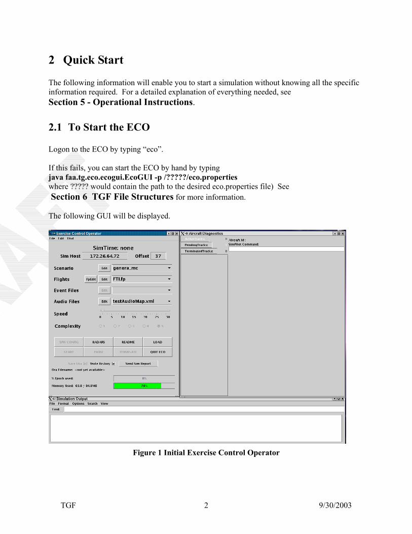
2.1 To Start the ECO Logon to the ECO by typing “eco”. If this fails, you can start the ECO by hand by typing java faa.tg.eco.ecogui.EcoGUI -p /?????/eco.properties where ????? would contain the path to the desired eco.properties file) See Section 6 TGF File Structures for more information. The following GUI will be displayed.
Figure 1 Initial Exercise Control Operator
TGF 9/30/2003 3
Figure 2 The Sim Host displays your IP Address and the Offset displays your IP Port Offset. Both fields are found by auto discover, but if that has failed, it must be corrected. You must confirm that both fields are correct in order for the SimPilot Stations to work properly. For more information about these settings, see Sections 5.1.3 Sim Host and 5.1.4 Offset.
2.2 Choose options for simulation The following choices must be made before starting the ECO: The default scenario is displayed or another scenario can be selected from the dropdown box. The default flight plan is displayed or choose another flight plan sample from the dropdown box. Both the default scenario and default flight plan sample are loaded from the eco.properties file. See Section 6.1 Eco.Properties file for more information. Radars can be set up if desired before loading the scenario. All other selections are optional, and are further described in later chapters.
TGF 9/30/2003 4
At this point the Load button can be pressed to start the simulation.
Figure 3 Simulation Options If you would like to use simpilots, they must be configured by pressing the SPW CONFIG button, which becomes available after the simulation has been loaded. After the scenario loads and the GUI fills out, the simulation can be started by pressing the START button.
TGF 9/30/2003 5
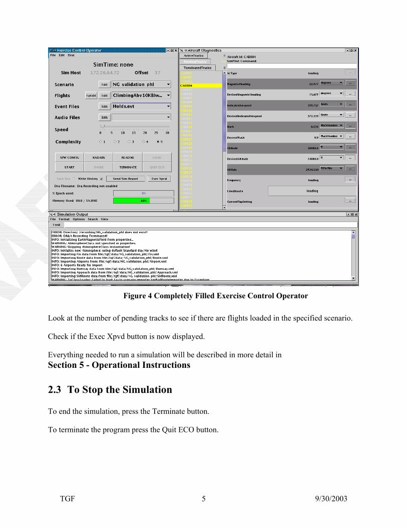
Figure 4 Completely Filled Exercise Control Operator Look at the number of pending tracks to see if there are flights loaded in the specified scenario. Check if the Exec Xpvd button is now displayed. Everything needed to run a simulation will be described in more detail in Section 5 - Operational Instructions
2.3 To Stop the Simulation To end the simulation, press the Terminate button. To terminate the program press the Quit ECO button.
3 Typical Simulation Configurations The following are different ways the ECO can be used:
• • Desiree • • •
Standalone with XPVD
Terminal (Stars Labs) En route (DSR/Host Labs) With other simulators – such as cockpit simulator
Standalone with XPVD By using the ECO on a single PC, you can make changes to flight plans. Desiree Host emulator - only uses positional information Terminal Takeoff and landings En route Between terminal airspace to drive any equipment that needs radar Other simulators Other simulators can create positional information, we can merge our positional information with that from another simulator into a single radar feed in the RBX’s.
TGF 9/30/2003 6
4 Available Platforms: The ECO can be run from any platform which supports the JAVA Virtual Machine (VM) including:
Personal PC • • • • •
Mainframe Unix Mac Linux
4.1 Things Needed: JAVA will need to be installed locally by CD or downloaded from the internet. TGF software Data files in TGF format Additional PC’s to act as Simpilot workstations (optional). Additional PC to act as a Radar device (optional) Voice/Audio equipment (optional) Air Traffic Controllers (optional)
TGF 9/30/2003 7
4.2 Installation Instructions JAVA Archives (JARS) will be provided on CD’s. Directory structure on local machine needs to be created in TGF tree format. See Section 6 TGF Data Files Structures for specific information. It can possibly be accessed through the internet. More information needed.
TGF 9/30/2003 8
TGF 9/30/2003 9
5 Operational Instructions To start the ECO, type “eco6”, “eco7”, “eco8”, or “eco9” (in lower case letters). The number following “eco” represents the If this fails, you can start the ECO by hand by typing java faa.tg.eco.ecogui.EcoGUI -p /?????/eco.properties where ????? would contain the path to the desired eco.properties file) See Section 6 TGF File Structures for more information. You will see the following GUIs appear.
Figure 5 Initial Exercise Control Operator
This display actually consists of three (3) GUIs which appear together as one. They consist of:
The Exercise Control Operator – used to control the operation of the simulation • • •
Each GUI will be individually explained in detail in the following sections.
TGF 9/30/2003 10
5.1 The Exercise Control Operator GUI
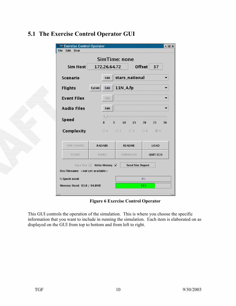
Figure 6 Exercise Control Operator This GUI controls the operation of the simulation. This is where you choose the specific information that you want to include in running the simulation. Each item is elaborated on as displayed on the GUI from top to bottom and from left to right.
5.1.1 Custom Menu Selections
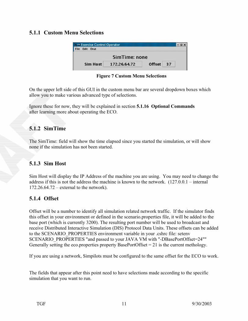
Figure 7 Custom Menu Selections
On the upper left side of this GUI in the custom menu bar are several dropdown boxes which allow you to make various advanced type of selections. Ignore these for now, they will be explained in section 5.1.16 Optional Commands after learning more about operating the ECO.
5.1.2 SimTime The SimTime: field will show the time elapsed since you started the simulation, or will show none if the simulation has not been started.
5.1.3 Sim Host Sim Host will display the IP Address of the machine you are using. You may need to change the address if this is not the address the machine is known to the network. (127.0.0.1 – internal 172.26.64.72 – external to the network).
5.1.4 Offset Offset will be a number to identify all simulation related network traffic. If the simulator finds this offset in your environment or defined in the scenario.properties file, it will be added to the base port (which is currently 3200). The resulting port number will be used to broadcast and receive Distributed Interactive Simulation (DIS) Protocol Data Units. These offsets can be added to the SCENARIO_PROPERTIES environment variable in your .cshrc file: setenv SCENARIO_PROPERTIES "and passed to your JAVA VM with "-DBasePortOffset=24"" Generally setting the eco.properties property BasePortOffset = 21 is the current methology. If you are using a network, Simpilots must be configured to the same offset for the ECO to work. The fields that appear after this point need to have selections made according to the specific simulation that you want to run.
TGF 9/30/2003 11
TGF 9/30/2003 12
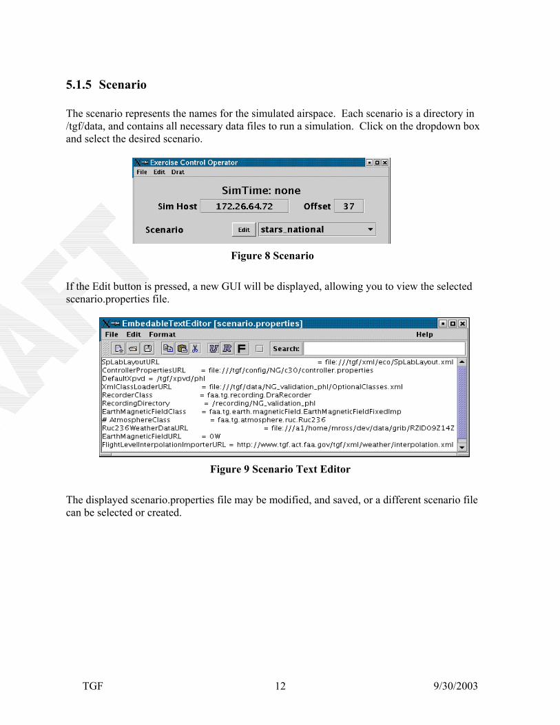
5.1.5 Scenario The scenario represents the names for the simulated airspace. Each scenario is a directory in /tgf/data, and contains all necessary data files to run a simulation. Click on the dropdown box and select the desired scenario.
Figure 8 Scenario
If the Edit button is pressed, a new GUI will be displayed, allowing you to view the selected scenario.properties file.
Figure 9 Scenario Text Editor The displayed scenario.properties file may be modified, and saved, or a different scenario file can be selected or created.
TGF 9/30/2003 13
5.1.6 Flights Flights represent the names for the flight plan samples available for that scenario. Click on the dropdown box and select the desired flight plan sample.
Figure 10 Flights If the Edit button is pressed, a new GUI is displayed, allowing you to view the selected flight plan sample, in this example - TurbopropTest.fp file.
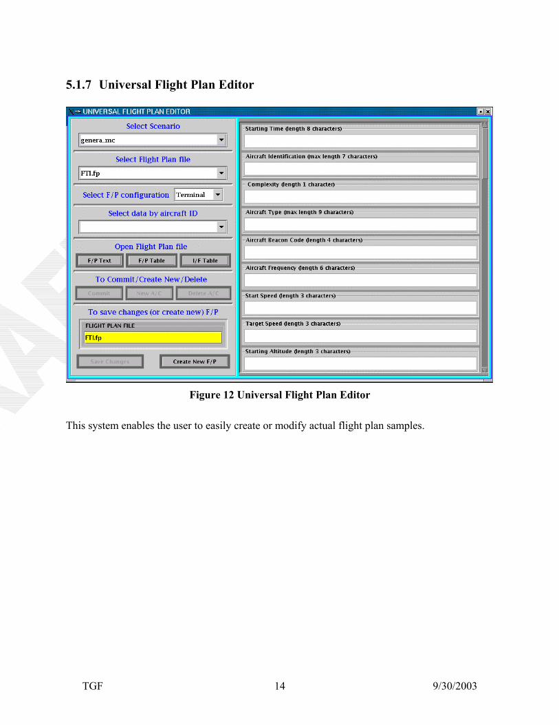
Figure 11 Flights Text Editor The displayed flight plan file may be modified and saved, or a different flight plan file can be selected or created. By pressing the left-most button on the Flights line - FpEdit, the Universal Flight Plan editor (UFP) program will start. (See Figure 12 below) It is a completely independent system. Instructions for this system can be found at: http://www.tgf.act.faa.gov/doc/ufp/FlightPlanUsersGuide.html.
This system enables the user to easily create or modify actual flight plan samples.
TGF 9/30/2003 15
5.1.8 Event Files
Figure 13 Event Files
The Event Files allow an action to be preplanned (scripted) that will happen during the simulation, and provides playback capabilities. Here again, click on the dropdown box to select the event file desired. When the Edit button is pressed, the following GUI will appear which displays the selected event file. It enables you to modify and save the displayed event file, or a different event file can be selected or created.
Figure 14 Event Files Text Editor
TGF 9/30/2003 16
5.1.9 Audio Files
Figure 15 Audio Files
The Audio Files displays the audio xml files available for the scenario. Here again, click on the dropdown box to select an audio file. If no files are displayed, the default audio xml file is used. When the Edit button is pressed, the following GUI appears.
Figure 16 Audio Files Text Editor The selected audio file is displayed and may be modified and saved, or a different audio file can be selected or created. The only information that may be changed is the Controller Channel and Audio Options. Depending on the audio system being used could change the name assigned to the Controller Channel. There are several Audio Options that may work with various types of audio systems.
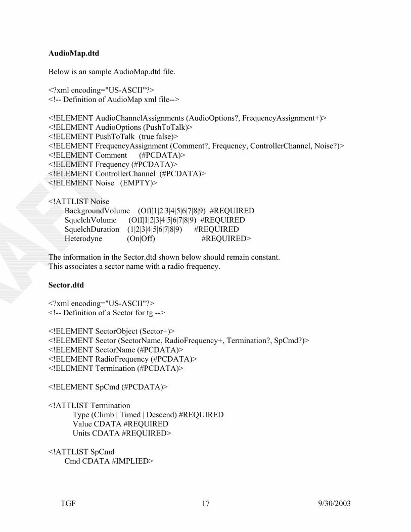
AudioMap.dtd Below is an sample AudioMap.dtd file. <?xml encoding="US-ASCII"?> <!-- Definition of AudioMap xml file--> <!ELEMENT AudioChannelAssignments (AudioOptions?, FrequencyAssignment+)> <!ELEMENT AudioOptions (PushToTalk)> <!ELEMENT PushToTalk (true|false)> <!ELEMENT FrequencyAssignment (Comment?, Frequency, ControllerChannel, Noise?)> <!ELEMENT Comment (#PCDATA)> <!ELEMENT Frequency (#PCDATA)> <!ELEMENT ControllerChannel (#PCDATA)> <!ELEMENT Noise (EMPTY)> <!ATTLIST Noise BackgroundVolume (Off|1|2|3|4|5|6|7|8|9) #REQUIRED SquelchVolume (Off|1|2|3|4|5|6|7|8|9) #REQUIRED SquelchDuration (1|2|3|4|5|6|7|8|9) #REQUIRED Heterodyne (On|Off) #REQUIRED> The information in the Sector.dtd shown below should remain constant. This associates a sector name with a radio frequency. Sector.dtd <?xml encoding="US-ASCII"?> <!-- Definition of a Sector for tg --> <!ELEMENT SectorObject (Sector+)> <!ELEMENT Sector (SectorName, RadioFrequency+, Termination?, SpCmd?)> <!ELEMENT SectorName (#PCDATA)> <!ELEMENT RadioFrequency (#PCDATA)> <!ELEMENT Termination (#PCDATA)> <!ELEMENT SpCmd (#PCDATA)> <!ATTLIST Termination Type (Climb | Timed | Descend) #REQUIRED Value CDATA #REQUIRED Units CDATA #REQUIRED> <!ATTLIST SpCmd Cmd CDATA #IMPLIED>
TGF 9/30/2003 17
5.1.10 Speed
Figure 17 Speed and Complexity
Speed is the amount of simulated time in seconds. This can be useful if you need to fast-forward simulations.
5.1.11 Complexity Complexity allows the flexibility of flying a subset of flights from one large traffic sample. The number in this field identifies the flight’s subset. If the operator selects this aircraft’s subset identifier it will be included in the sample along with all lower complexity level flights. The choices range from 1 to 5. If subsets of a large sample are not needed, then this field should be 1. Example: If Complexity 2 is chosen, only flights with Complexity Levels 1 and 2 will be included.
TGF 9/30/2003 18
TGF 9/30/2003 19
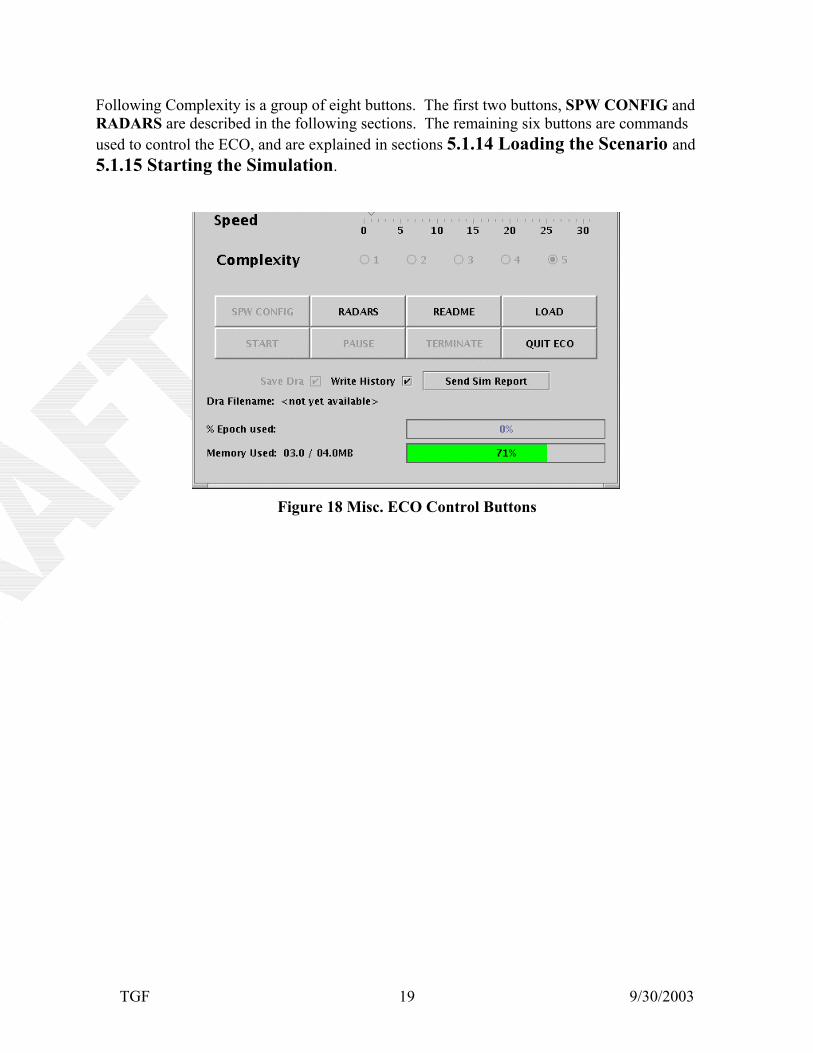
Following Complexity is a group of eight buttons. The first two buttons, SPW CONFIG and RADARS are described in the following sections. The remaining six buttons are commands used to control the ECO, and are explained in sections 5.1.14 Loading the Scenario and 5.1.15 Starting the Simulation.
Figure 18 Misc. ECO Control Buttons
TGF 9/30/2003 20
5.1.12 SPW CONFIG - Sim Pilot Workstations When the SPW CONFIG button is pressed, the following GUI is displayed. It allows you to select Simpilot Workstations to be included in your simulation. This process associates a simpilot workstation with an air-traffic control sector.
Figure 19 Empty Sim Pilot Workstations
The Select Simpilots GUI contains three parts. The first part which is displayed on the top left side of the GUI contains the control buttons.
Figure 20 Select Simpilot Controls
LOAD-LAST SETTINGS – loads your last saved selections ACCEPT and EXIT – confirms your simpilot selections CANCEL and EXIT- clears your selections which have not been saved RE-REQUEST SETTINGS – to see which simpilot stations are available CLEAR SIMPILOT – select this button then select each simpilot station to clear SAVE SETTINGS – saves your selections (as .spcfg file) LOAD SETTINGS – from a saved .spcfg file Xpvd Map – choose from selections displayed in the dropdown box. The names represent folders in /tgf/xpvd/data which contain text files used to display the desired Xpvd configuration.
TGF 9/30/2003 21
TGF 9/30/2003 22
The upper right portion of the GUI displays the lab layout of simpilot workstation. Any station number that is not available for use is displayed in gray. All available workstations are displayed in black and say Available under the station number.
Figure 21 Simpilot Workstations
The lower part of the GUI displays colored blocks, each representing a sector and frequency.
Figure 22 Bottom Portion of Simpilot Workstation
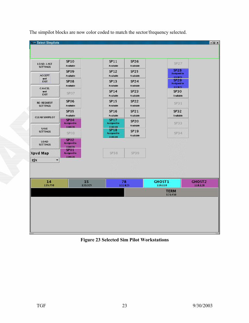
To assign a simpilot to a sector, click on a sector (a colored block from the bottom of the GUI), and then click on the Simpilot Workstation(s) that you would like to use.
TGF 9/30/2003 23
The simpilot blocks are now color coded to match the sector/frequency selected.
Figure 23 Selected Sim Pilot Workstations
TGF 9/30/2003 24
The entire time the simulation is running, this condensed GUI is displayed to show which simpilot workstations are active. While the simpilot station is in the process of being opened, the color surrounds the number.
Figure 24 Sim Pilot Workstations Being Opened When the blocks are fully colored, all workstations are ready.
Figure 25 Sim Pilot Workstations Ready
TGF 9/30/2003 25
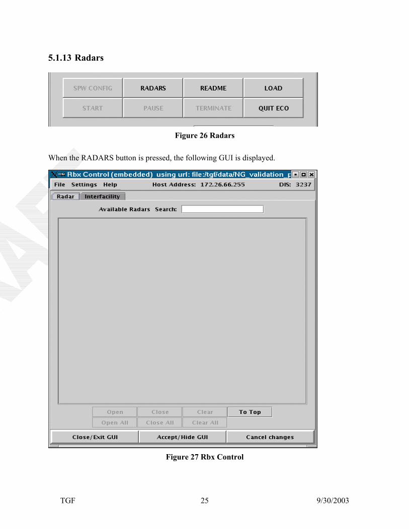
5.1.13 Radars
Figure 26 Radars
When the RADARS button is pressed, the following GUI is displayed.
Figure 27 Rbx Control
TGF 9/30/2003 26
The RbxControl allows the user to configure a RbxRadar/RbxFacility for data processing. It is a visual display of what data will be broadcast to a RbxDevice. Such data includes the RbxRadar/Facility to open, a RbxDevice to broadcast to, weather or surveillance files, which port to broadcast on, baud rates and auto-handoffs ranges.
Figure 28 Rbx Control
TGF 9/30/2003 27
Figure 29 One Rbx Control
The Wx box corresponds to the weather line on terminal radars. Select a pre-made weather file to simulate weather on this radar. The Srv box Bytex: none button when pressed displays the following GUI. It is used to asign a rbx device for radar communications (required).
Figure 30 Available Rbx Devices
TGF 9/30/2003 28
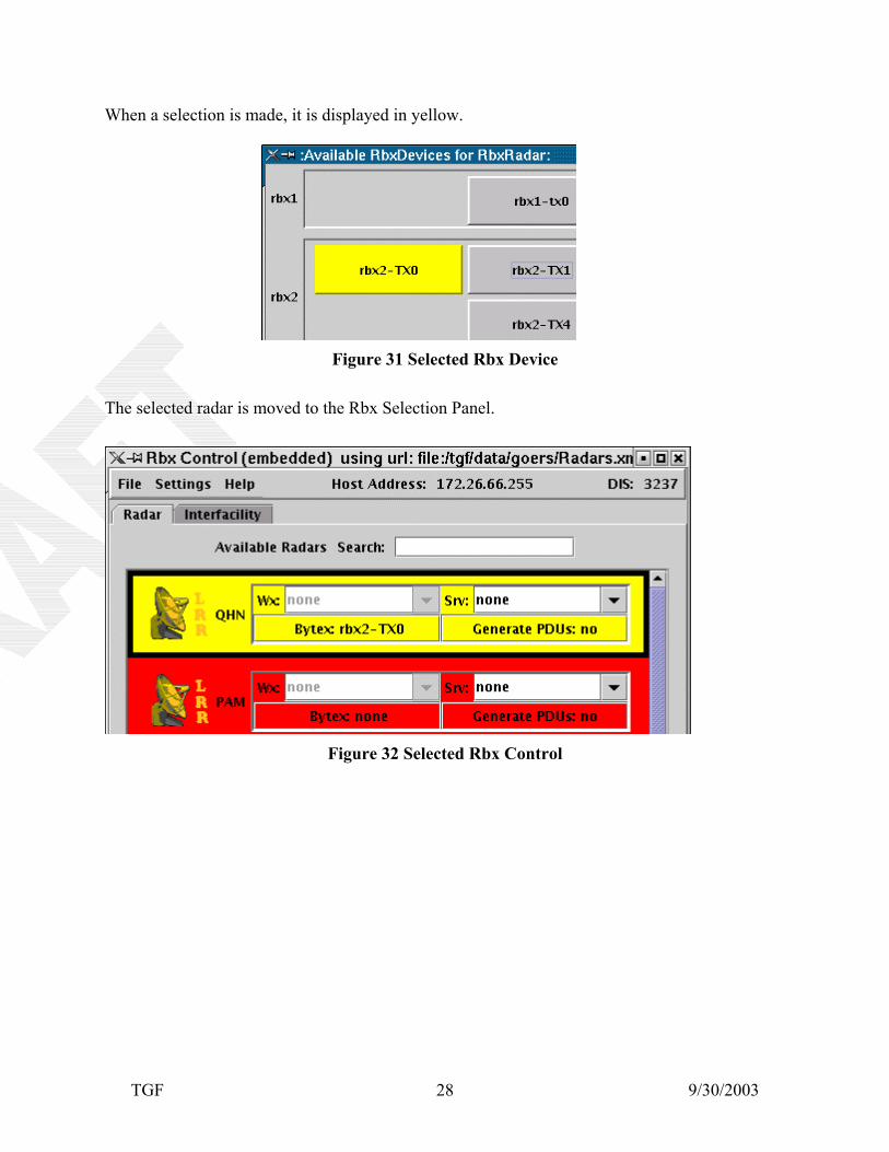
When a selection is made, it is displayed in yellow.
Figure 31 Selected Rbx Device
The selected radar is moved to the Rbx Selection Panel.
Figure 32 Selected Rbx Control
TGF 9/30/2003 29
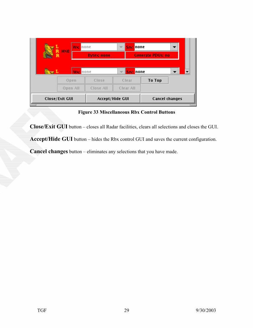
Figure 33 Miscellaneous Rbx Control Buttons
Close/Exit GUI button – closes all Radar facilities, clears all selections and closes the GUI. Accept/Hide GUI button – hides the Rbx control GUI and saves the current configuration. Cancel changes button – eliminates any selections that you have made.
TGF 9/30/2003 30
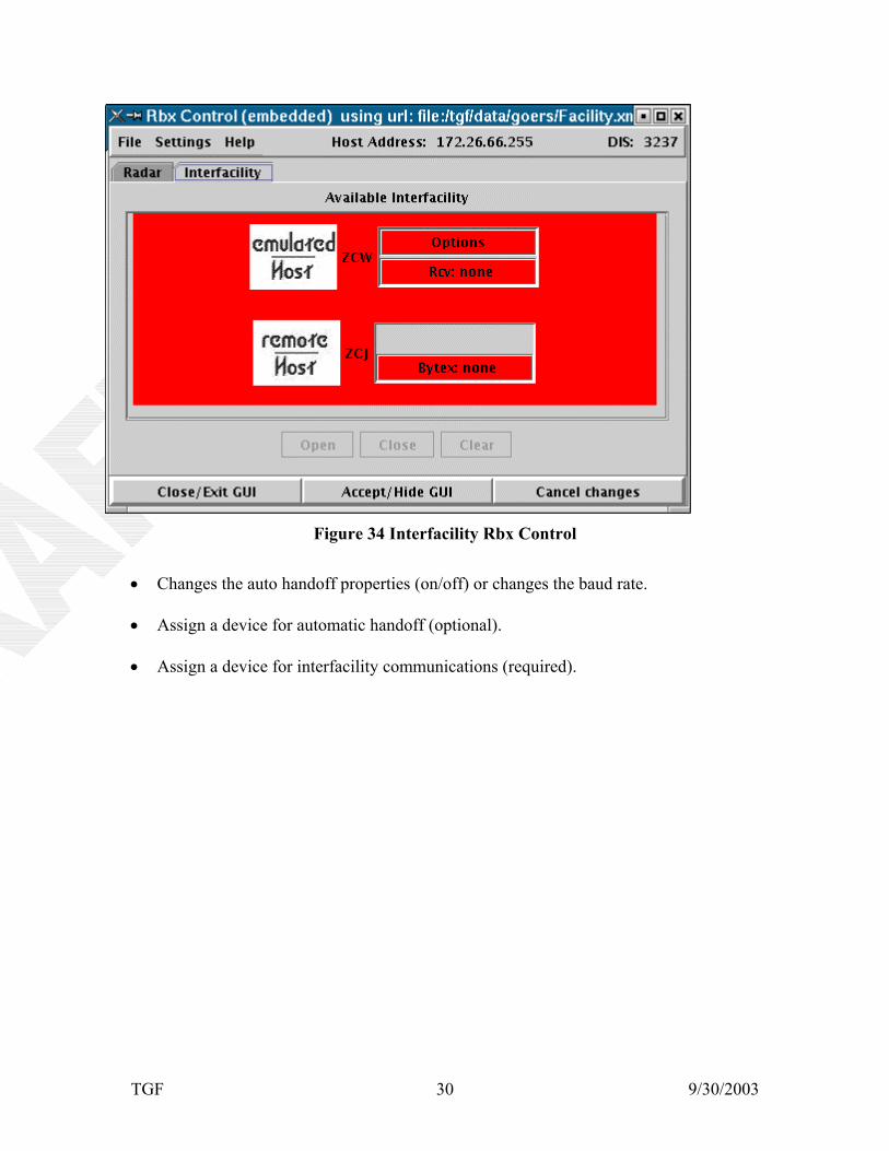
Figure 34 Interfacility Rbx Control
Changes the auto handoff properties (on/off) or changes the baud rate. •
•
•
Assign a device for automatic handoff (optional).
Assign a device for interfacility communications (required).
TGF 9/30/2003 31
5.1.14 Loading the Scenario
Figure 35 Loading the Scenario
When your selections are completed, you need to press the LOAD button to load the scenario. The following GUI will appear while the scenario is being loaded. This may take several minutes depending on your system
Figure 36 Waiting for Scenario to Load While the scenario is being loaded, information will start to appear in the Simulation Output GUI (which is located below The Exercise Control Operator GUI).
Figure 37 Simulation Output
TGF 9/30/2003 32
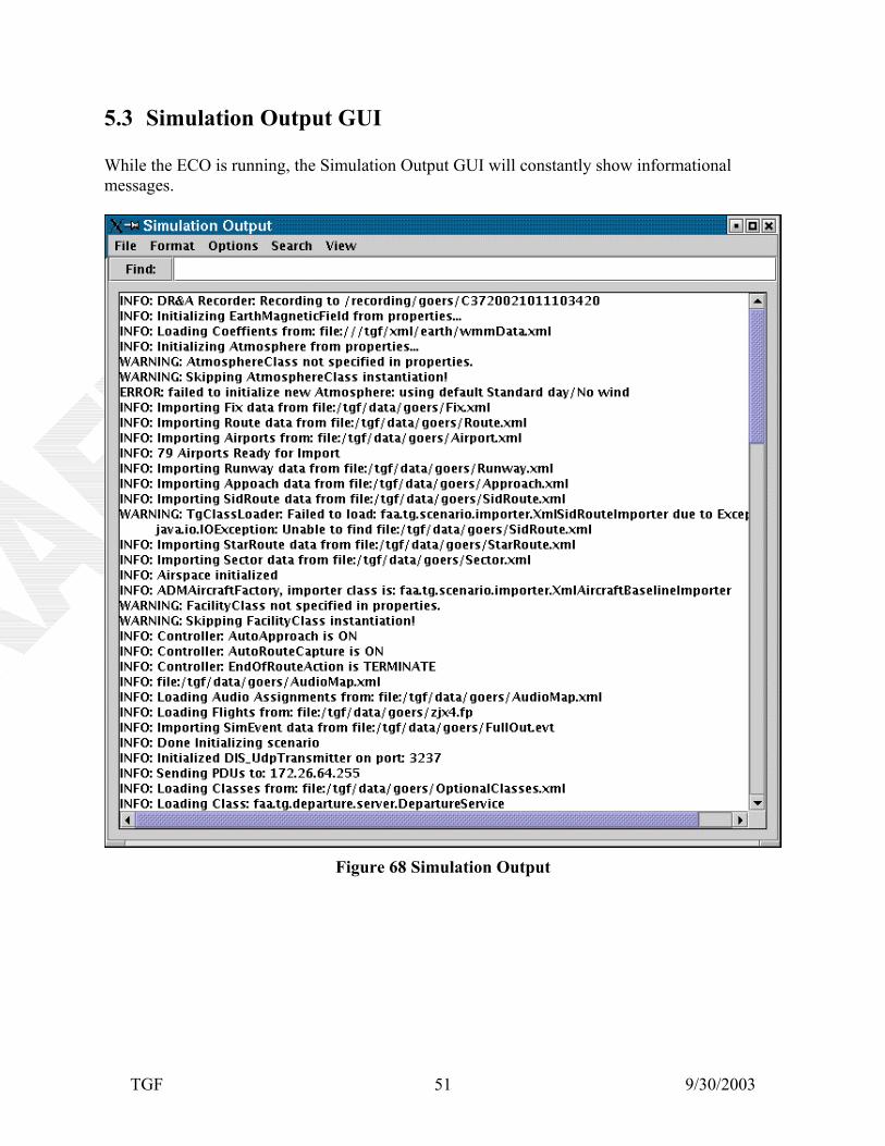
The messages consist of INFO, ERROR, and WARNING messages. They tell which files the scenario is using, and shows any warnings or errors that may have occurred. For more information, refer to section 5.3 Simulation Output GUI. To alert you to the fact that the scenario is finished loading, you will see the informational message displayed : INFO: EXERCISE READY.
Figure 38 Exercise Ready
After loading the scenario, the Exec Xpvd button appears (if this option was put in as an optionally loaded class.
Figure 39 Exec Xpvd
TGF 9/30/2003 33
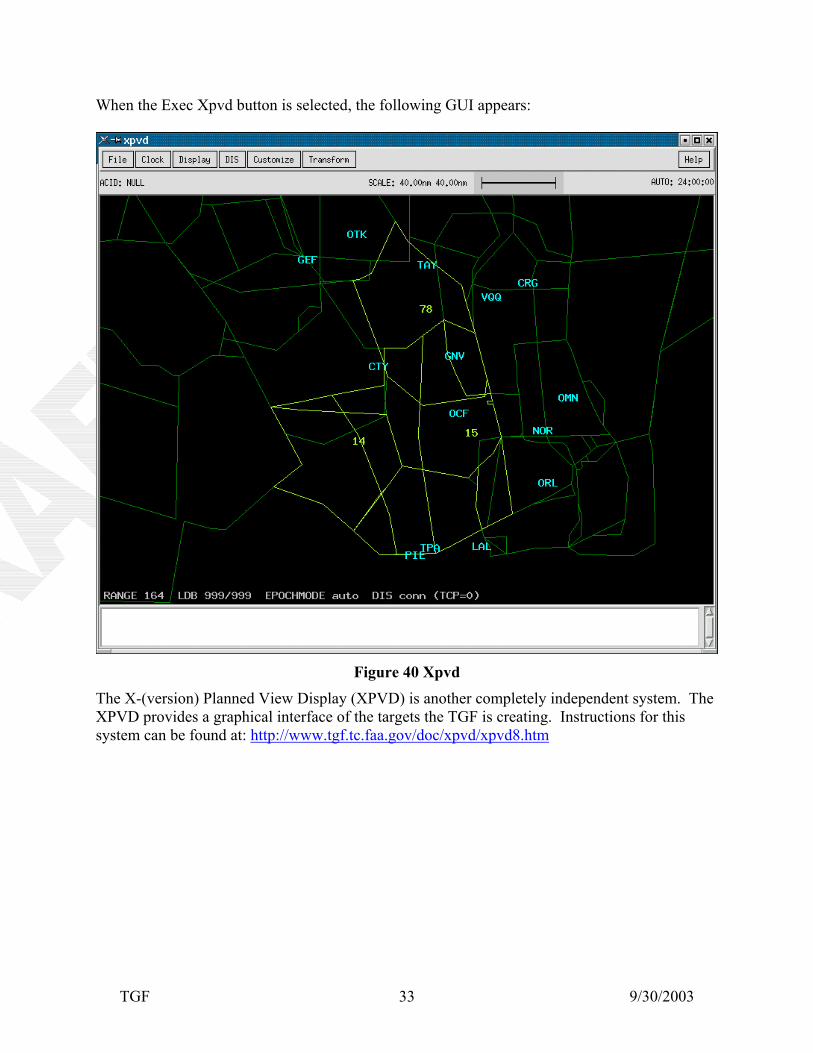
When the Exec Xpvd button is selected, the following GUI appears:
Figure 40 Xpvd The X-(version) Planned View Display (XPVD) is another completely independent system. The XPVD provides a graphical interface of the targets the TGF is creating. Instructions for this system can be found at: http://www.tgf.tc.faa.gov/doc/xpvd/xpvd8.htm
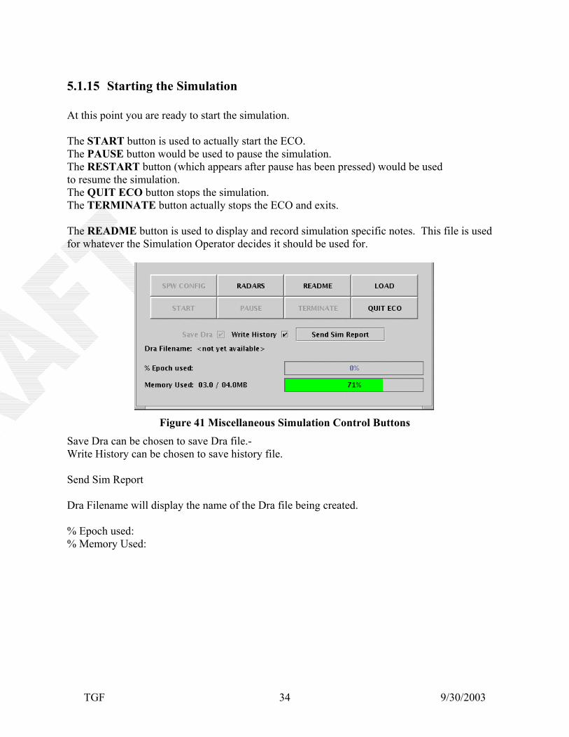
5.1.15 Starting the Simulation At this point you are ready to start the simulation. The START button is used to actually start the ECO. The PAUSE button would be used to pause the simulation. The RESTART button (which appears after pause has been pressed) would be used to resume the simulation. The QUIT ECO button stops the simulation. The TERMINATE button actually stops the ECO and exits. The README button is used to display and record simulation specific notes. This file is used for whatever the Simulation Operator decides it should be used for.
Figure 41 Miscellaneous Simulation Control Buttons Save Dra can be chosen to save Dra file.- Write History can be chosen to save history file. Send Sim Report Dra Filename will display the name of the Dra file being created. % Epoch used: % Memory Used:
TGF 9/30/2003 35
5.1.16 ECO Custom Menu On the upper left side of the GUI in the custom menu bar are several dropdown menu boxes. The File dropdown box allows you to create a new scenario. (Presently not used) The Edit dropdown box shows the following choices:
Figure 42 ECO Custom Menu Selecting any of the above choices will invoke the schema directed XML editor used for scenario configuration files. Schema defines the elements of your XML files for better validation. Optional Classes are found in a separate xml file. The information found in this file can cause various changes buttons on different GUIs and in some instances, which GUIs will be displayed.
5.1.17 Drat – Data Reduction Analysis Tool DRAT was developed to generate reports on air traffic control simulations for data analysis. Researchers can use this tool to analyze and interpret various sets of dependent variables that relate to both air traffic system performance and individual controller performance. Analysts will be able to evaluate the output of the tool with statistical packages without manual elimination of extraneous raw data. The Menu-driven GUIs allow easy customization of data output and tailoring of data reports to meet the research analysis requirements of the studies being conducted. The tool's Menu-driven interface allows the selection of TGF simulation recordings. The analyst can select data from sets of variables for output, process summary statistics based on user-specifiable time blocks, and print the output generated to the desired format. The output can be printed to either a text format for reading or to a comma-delimited format compatible with spreadsheet import files such as those used by MS-Excel, Lotus 1-2-3, or Quattro Pro. Frequently used data output formats can be saved and are accessible through Menus. Among the types of reports the data reduction and analysis tool is capable of producing are system complexity measurement reports, system activity/load measurement reports, and conflict reports on aircraft violation of separation requirements, aircraft characteristic reports, and flight status reports. Frequencies and duration of events can be determined over the length of the simulation or over specifiable intervals of time. The reports can be adapted to meet the analysts' needs and, as such, are highly customizable.
TGF 9/30/2003 36
TGF 9/30/2003 37
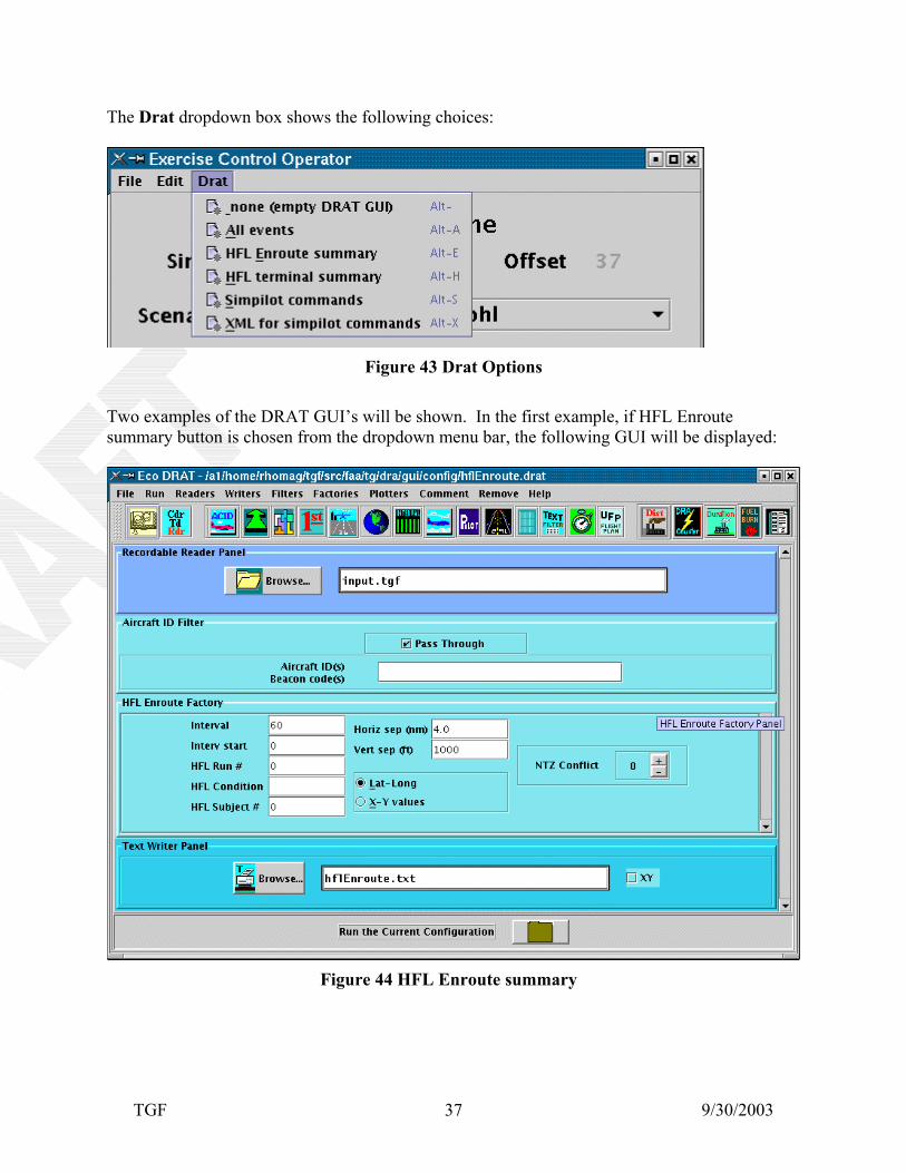
The Drat dropdown box shows the following choices:
Figure 43 Drat Options Two examples of the DRAT GUI’s will be shown. In the first example, if HFL Enroute summary button is chosen from the dropdown menu bar, the following GUI will be displayed:
Figure 44 HFL Enroute summary
TGF 9/30/2003 38
Figure 45 Drat Options
In the next example, by selecting Simpilot Commands, the following GUI is displayed:
Figure 46 Drat Simpilot Commands If additional information regarding how to use DRAT, press the Help button on the right side of the custom menu bar. This will display the DRAT User's Guide. It can also be found in tgf/src/faa/tg/dra/gui/help.html.
TGF 9/30/2003 39
5.1.18 Departure
Figure 47 Departure
The Departure dropdown box will start the departure GUIs.
Figure 48 Departure Control Panel
TGF 9/30/2003 40
5.2 The Aircraft Diagnostics GUI
Figure 49 Initial Aircraft Diagnostics
The Aircraft Diagnostics GUI is used primarily to display detailed specifications about the flights used in the simulation. Before the scenario is loaded, this GUI appears empty as shown. Active Tracks: will display the number of flights that are currently flying (in green). Pending Tracks: will display the number of flights that haven't started (in yellow). Terminated Tracks: will display the number of flights that have been completed (in red).
TGF 9/30/2003 41
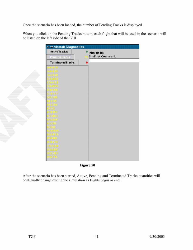
Once the scenario has been loaded, the number of Pending Tracks is displayed. When you click on the Pending Tracks button, each flight that will be used in the scenario will be listed on the left side of the GUI.
Figure 50 After the scenario has been started, Active, Pending and Terminated Tracks quantities will continually change during the simulation as flights begin or end.
TGF 9/30/2003 42
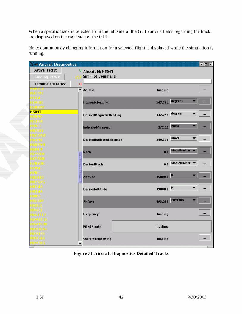
When a specific track is selected from the left side of the GUI various fields regarding the track are displayed on the right side of the GUI. Note: continuously changing information for a selected flight is displayed while the simulation is running.
Figure 51 Aircraft Diagnostics Detailed Tracks
TGF 9/30/2003 43
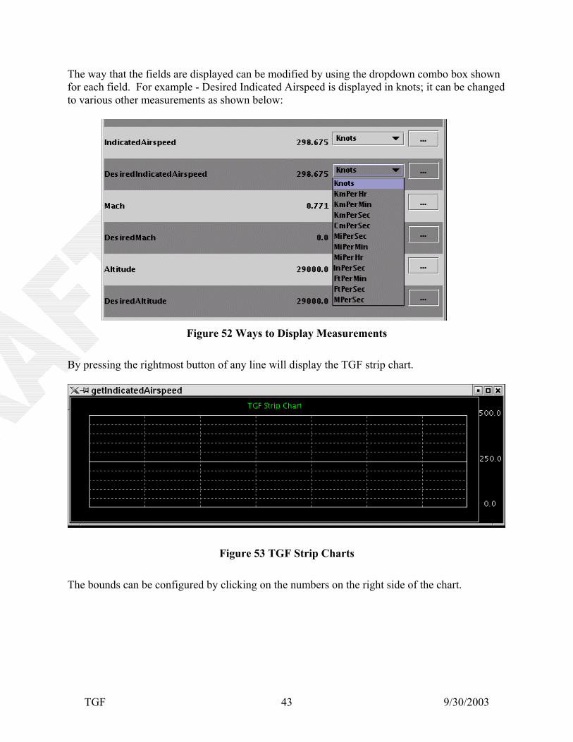
The way that the fields are displayed can be modified by using the dropdown combo box shown for each field. For example - Desired Indicated Airspeed is displayed in knots; it can be changed to various other measurements as shown below:
Figure 52 Ways to Display Measurements
By pressing the rightmost button of any line will display the TGF strip chart.
Figure 53 TGF Strip Charts The bounds can be configured by clicking on the numbers on the right side of the chart.
TGF 9/30/2003 44
5.2.1 Customize Study
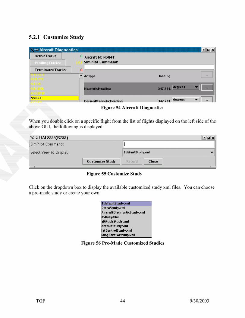
Figure 54 Aircraft Diagnostics When you double click on a specific flight from the list of flights displayed on the left side of the above GUI, the following is displayed:
Figure 55 Customize Study Click on the dropdown box to display the available customized study xml files. You can choose a pre-made study or create your own.
Figure 56 Pre-Made Customized Studies
TGF 9/30/2003 45
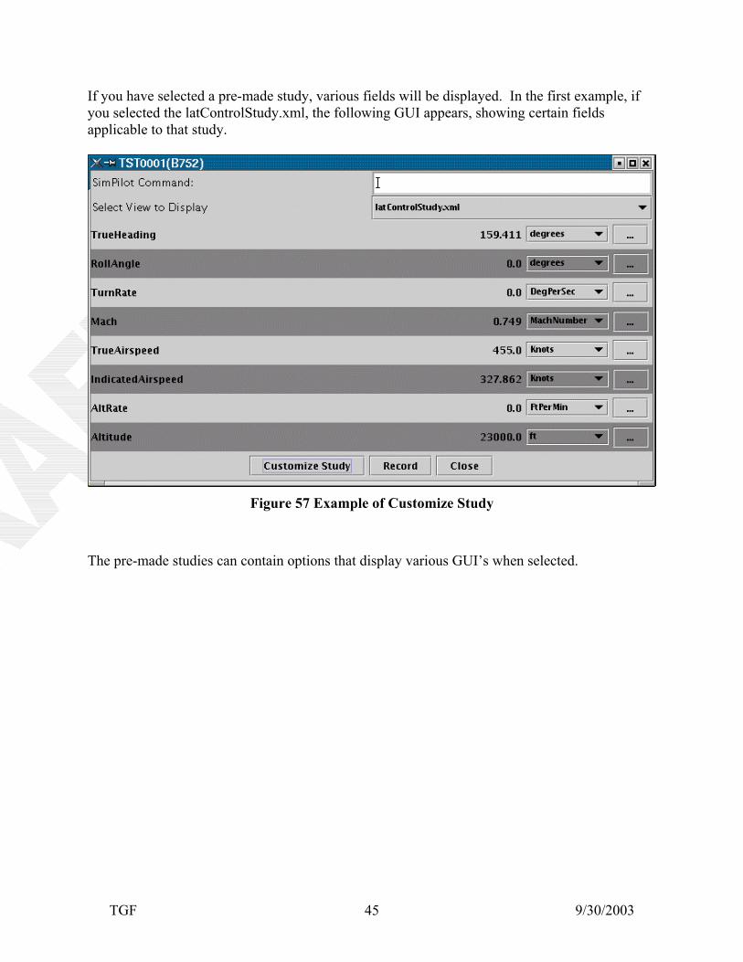
If you have selected a pre-made study, various fields will be displayed. In the first example, if you selected the latControlStudy.xml, the following GUI appears, showing certain fields applicable to that study.
Figure 57 Example of Customize Study
The pre-made studies can contain options that display various GUI’s when selected.
TGF 9/30/2003 46
In the next example, if you selected the 2atcaStudy.xml, the following GUI will be displayed and the three TGF Strip Chart GUI’s shown on the following page are also displayed.
Figure 58 More Detailed Customize Study
TGF 9/30/2003 47
Figure 59 TGF Strip Charts
TGF 9/30/2003 48
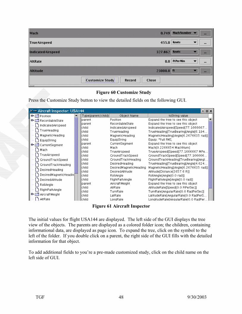
Figure 60 Customize Study Press the Customize Study button to view the detailed fields on the following GUI.
Figure 61 Aircraft Inspector The initial values for flight USA144 are displayed. The left side of the GUI displays the tree view of the objects. The parents are displayed as a colored folder icon; the children, containing informational data, are displayed as page icon. To expand the tree, click on the symbol to the left of the folder. If you double click on a parent, the right side of the GUI fills with the detailed information for that object. To add additional fields to you’re a pre-made customized study, click on the child name on the left side of GUI.
TGF 9/30/2003 49
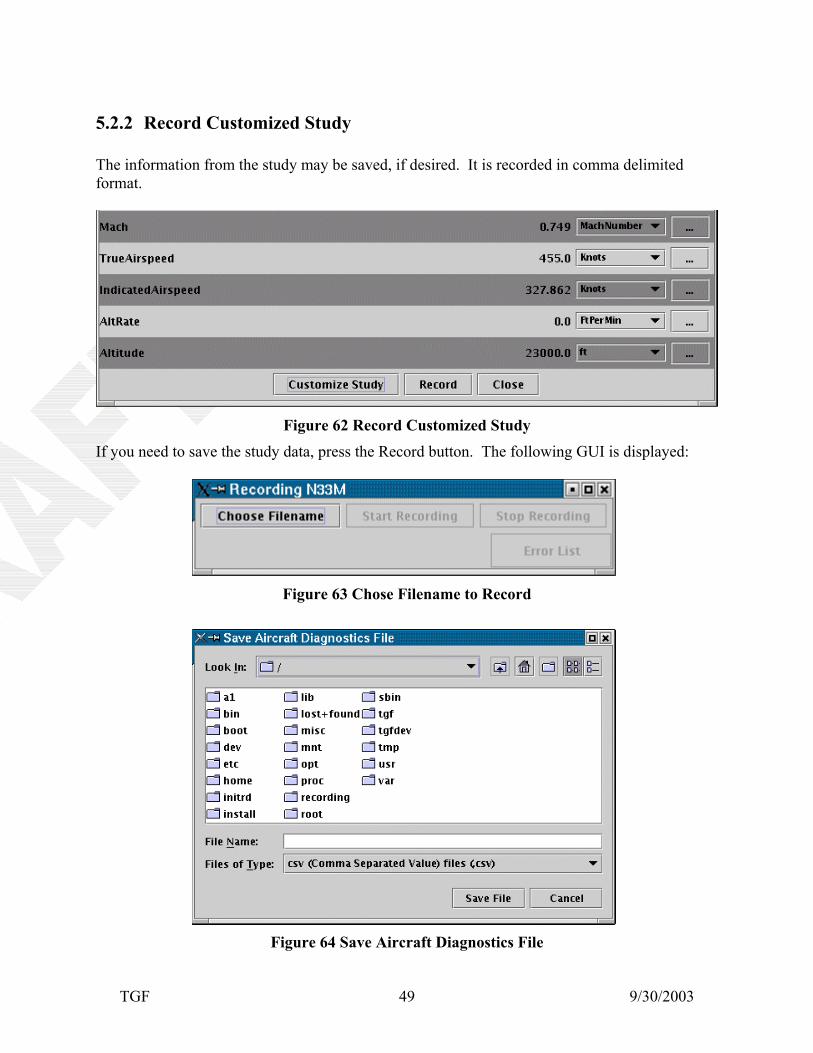
5.2.2 Record Customized Study The information from the study may be saved, if desired. It is recorded in comma delimited format.
Figure 62 Record Customized Study If you need to save the study data, press the Record button. The following GUI is displayed:
Figure 63 Chose Filename to Record
Figure 64 Save Aircraft Diagnostics File
TGF 9/30/2003 50
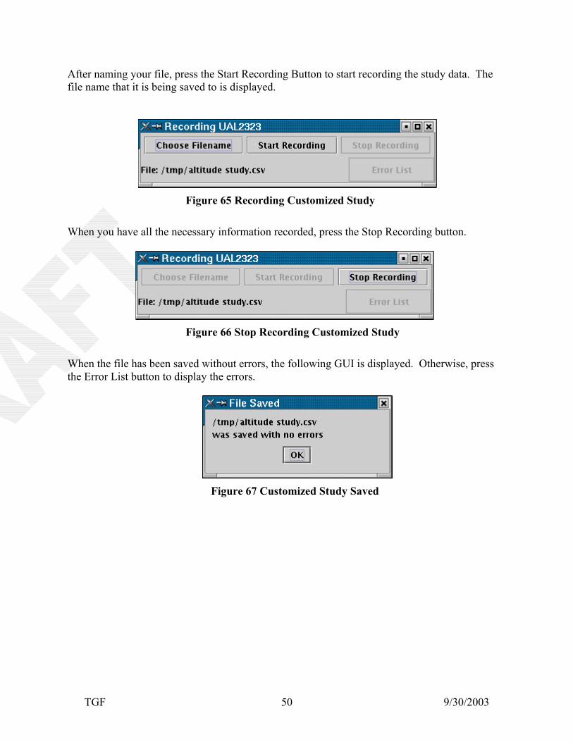
After naming your file, press the Start Recording Button to start recording the study data. The file name that it is being saved to is displayed.
Figure 65 Recording Customized Study
When you have all the necessary information recorded, press the Stop Recording button.
Figure 66 Stop Recording Customized Study When the file has been saved without errors, the following GUI is displayed. Otherwise, press the Error List button to display the errors.
Figure 67 Customized Study Saved
TGF 9/30/2003 51
5.3 Simulation Output GUI While the ECO is running, the Simulation Output GUI will constantly show informational messages.
Figure 68 Simulation Output
TGF 9/30/2003 52
•
•
•
•
•
•
At the top of this GUI in the custom menu bar, there are several dropdown box selections for ways of displaying, and saving the simulation output messages. They are:
File - The simulation output messages can be saved or saved and renamed. These messages are normally saved in a TGF Messages log file (.log).
Format - The font for the display of the messages can be changed.
Options - Displays Message Headers or AutoScroll.
Search – Find or Find Again.
View – Allows you to view only selected messages, all or none.
Find: Allows you to find specific information in the messages.
Figure 69 Ways to View Simulation Output
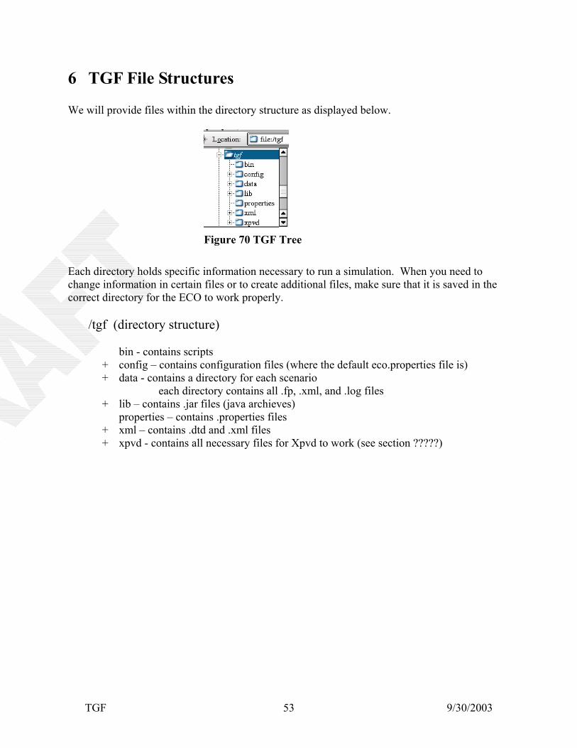
6 TGF File Structures We will provide files within the directory structure as displayed below.
Figure 70 TGF Tree
Each directory holds specific information necessary to run a simulation. When you need to change information in certain files or to create additional files, make sure that it is saved in the correct directory for the ECO to work properly.
/tgf (directory structure)
bin - contains scripts + config – contains configuration files (where the default eco.properties file is) + data - contains a directory for each scenario
each directory contains all .fp, .xml, and .log files + lib – contains .jar files (java archieves) properties – contains .properties files + xml – contains .dtd and .xml files + xpvd - contains all necessary files for Xpvd to work (see section ?????)
TGF 9/30/2003 53
6.1 Eco.Properties File The location of the eco.properties file must be specified as a run time parameter. It contains locations of various files and other specific information necessary to run a simulation. The SimDirBase must contain the location of the individual scenario directories. The Default Scenario and FlightSample selects which to display when first bringing up the ECO. Below is a sample eco.properties file: DefaultScenario = genera_mc DefaultFlightSample = FTI.fp BasePortOffset = 37 SimulationBroadcast = 172.26.64.255 SimulatorIPaddr = 172.26.64.72 ## TgMsg MessageEvent Logging setup (empty file string goes to stderr/stdout) TgMsgLogType0 = faa.tg.message.MessageEvent TgMsgLogFile0 = #TgMsgLogType1 = faa.tg.message.ErrorMessageEvent #TgMsgLogFile1 = out.err SpLabLayoutURL = http://www.tgf.act.faa.gov/tgf/xml/eco/SpLabLayout.xml #SectorImporterClass = faa.tg.scenario.importer.XmlSectorImporter #SectorImporterURL = http://www.tgf.act.faa.gov/tgf/scenbin/lax_aep/sector.xml TgMsgDebugPropertiesURL =
TGF 9/30/2003 54
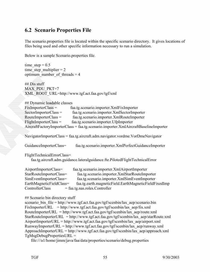
6.2 Scenario Properties File The scenario.properties file is located within the specific scenario directory. It gives locations of files being used and other specific information necessary to run a simulation. Below is a sample Scenario.properties file. time_step = 0.5 time_step_multiplier = 2 optimum_number_of_threads = 4 ## Dis stuff MAX_PDU_PKT=7 XML_ROOT_URL=http://www.tgf.act.faa.gov/tgf/xml ## Dynamic loadable classes FixImporterClass = faa.tg.scenario.importer.XmlFixImporter SectorImporterClass = faa.tg.scenario.importer.XmlSectorImporter RouteImporterClass = faa.tg.scenario.importer.XmlRouteImporter FlightImporterClass = faa.tg.scenario.importer.UfpImporter AircraftFactoryImporterClass = faa.tg.scenario.importer.XmlAircraftBaselineImporter NavigatorImporterClass = faa.tg.aircraft.adm.navigator.vordme.VorDmeNavigator GuidanceImporterClass= faa.tg.scenario.importer.XmlPerfectGuidanceImporter FlightTechnicalErrorClass= faa.tg.aircraft.adm.guidance.lateralguidance.fte.PilotedFlightTechnicalError AirportImporterClass= faa.tg.scenario.importer.XmlAirportImporter StarRouteImporterClass= faa.tg.scenario.importer.XmlStarRouteImporter SimEventImporterClass= faa.tg.scenario.importer.XmlSimEventImporter EarthMagneticFieldClass= faa.tg.earth.magneticField.EarthMagneticFieldFixedImp ControllerClass = faa.tg.nas.roles.Controller ## Scenario bin directory stuff scenario_bin_file = http://www.tgf.act.faa.gov/tgf/scenbin/lax_aep/scenario.bin FixImporterURL = http://www.tgf.act.faa.gov/tgf/scenbin/lax_aep/fix.xml RouteImporterURL = http://www.tgf.act.faa.gov/tgf/scenbin/lax_aep/route.xml StarRouteImporterURL = http://www.tgf.act.faa.gov/tgf/scenbin/lax_aep/starRoute.xml AirportImporterURL = http://www.tgf.act.faa.gov/tgf/scenbin/lax_aep/airport.xml RunwayImporterURL = http://www.tgf.act.faa.gov/tgf/scenbin/lax_aep/runway.xml ApproachImporterURL = http://www.tgf.act.faa.gov/tgf/scenbin/lax_aep/approach.xml TgMsgDebugPropertiesURL = file:///a1/home/jimm/java/faa/data/properties/scenario/debug.properties
TGF 9/30/2003 55
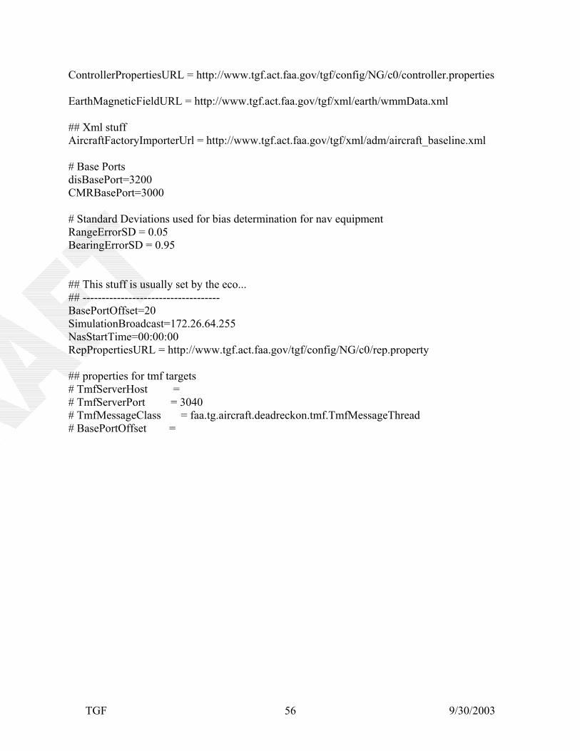
ControllerPropertiesURL = http://www.tgf.act.faa.gov/tgf/config/NG/c0/controller.properties EarthMagneticFieldURL = http://www.tgf.act.faa.gov/tgf/xml/earth/wmmData.xml ## Xml stuff AircraftFactoryImporterUrl = http://www.tgf.act.faa.gov/tgf/xml/adm/aircraft_baseline.xml # Base Ports disBasePort=3200 CMRBasePort=3000 # Standard Deviations used for bias determination for nav equipment RangeErrorSD = 0.05 BearingErrorSD = 0.95 ## This stuff is usually set by the eco... ## ------------------------------------ BasePortOffset=20 SimulationBroadcast=172.26.64.255 NasStartTime=00:00:00 RepPropertiesURL = http://www.tgf.act.faa.gov/tgf/config/NG/c0/rep.property ## properties for tmf targets # TmfServerHost = # TmfServerPort = 3040 # TmfMessageClass = faa.tg.aircraft.deadreckon.tmf.TmfMessageThread # BasePortOffset =
TGF 9/30/2003 56
6.3 Scenario Properties Names The ScenarioPropertiesNames interface contains a common place for the names of keys in the scenario properties object. Below is a sample ScenarioPropertiesNames: public interface ScenarioPropertiesNames { public static final String REMOTE_ECO_GUI_PORT = "RemoteEcoGUIPort"; public static final String ATMOSPHERE_CLASS = "AtmosphereClass"; public static final String RECORDER_CLASS = "RecorderClass"; public static final String CONTROLLER_CLASS = "ControllerClass"; public static final String FACILITY_CLASS = "FacilityClass"; public static final String FIX_IMPORTER_CLASS = "FixImporterClass"; public static final String ROUTE_IMPORTER_CLASS = "RouteImporterClass"; public static final String FLIGHT_IMPORTER_CLASS = "FlightImporterClass"; public static final String AIRPORT_IMPORTER_CLASS = "AirportImporterClass"; public static final String STAR_ROUTE_IMPORTER_CLASS = "StarRouteImporterClass"; public static final String SID_ROUTE_IMPORTER_CLASS = "SidRouteImporterClass"; public static final String SIM_EVENT_IMPORTER_CLASS = "SimEventImporterClass"; public static final String SECTOR_IMPORTER_CLASS = "SectorImporterClass"; public static final String EARTH_MAGNETIC_FIELD_CLASS = "EarthMagneticFieldClass"; public static final String AIRCRAFT_FACTORY_IMPORTER_CLASS = "AircraftFactoryImporterClass"; public static final String AUDIO_CONTROL_CLASS = "AudioControlClass"; public static final String AUDIO_CONTROL_URL = "AudioControlURL"; public static final String FIX_IMPORTER_URL = "FixImporterURL"; public static final String FLIGHT_IMPORTER_URL = "FlightImporterUrl"; public static final String ROUTE_IMPORTER_URL = "RouteImporterURL"; public static final String REP_PROPERTIES_URL = "RepPropertiesURL"; public static final String RUNWAY_IMPORTER_URL = "RunwayImporterURL"; public static final String AIRPORT_IMPORTER_URL = "AirportImporterURL"; public static final String APPROACH_IMPORTER_URL = "ApproachImporterURL"; public static final String STAR_ROUTE_IMPORTER_URL = "StarRouteImporterURL"; public static final String Sid_ROUTE_IMPORTER_URL = "SidRouteImporterURL"; public static final String SIM_EVENT_IMPORTER_URL = "SimEventImporterURL"; public static final String FLIGHT_LEVEL_INTERPOLATION_IMPORTER_URL = "FlightLevelInterpolationImporterURL"; public static final String SECTOR_IMPORTER_URL = "SectorImporterURL"; public static final String EARTH_MAGNETIC_FIELD_URL = "EarthMagneticFieldURL";
TGF 9/30/2003 57
public static final String CONTROLLER_PROPERTIES_URL = "ControllerPropertiesURL"; public static final String TGMSG_DEBUG_PROPERTIES_URL= "TgMsgDebugPropertiesURL"; public static final String AIRCRAFT_FACTORY_IMPORTER_URL = "AircraftFactoryImporterUrl"; public static final String RUC236_WEATHER_DATA_URL = "Ruc236WeatherDataURL"; public static final String SCENARIO_BIN_FILE = "scenario_bin_file"; public static final String SIM_TIME = "SimulationTime"; public static final String NAS_START_TIME = "NasStartTime"; public static final String MAX_PDU_PKT = "MAX_PDU_PKT"; public static final String DIS_BASE_PORT = "disBasePort"; public static final String CMR_BASE_PORT = "CMRBasePort"; public static final String BASE_PORT_OFFSET = "BasePortOffset"; public static final String SIMULATION_BROADCAST = "SimulationBroadcast"; public static final String TIME_STEP = "time_step"; public static final String TIME_STEP_MULTIPLIER = "time_step_multiplier"; public static final String OPTIMUM_NUMBER_OF_THREADS = "optimum_number_of_threads"; public static final String RECORDING_DIRECTORY = "RecordingDirectory"; /** * Specify the recording file name * * Special characters will be substituted for useful scenario value substrings: * * @ chassis# (base port) as C## * * date as YYYY-MM-DD * ) date as YYYYMMDD * $ date/time as YYYYMMDDHHMMSS * + date/time as YYYY-MM-DD-"T"HHMM * ^ flightplan filename (without .fp) * # run number (prevents duplicate names) * (## - run number as two digits) * (### - run number as three digits...) * * For example, the default template string is specified by:"@-*-R###" * * (yields: "C##-YYYY-MM-DD-R###"). */ public static final String RECORDING_FILENAME = "RecordingFilename"; public static final String RECORDING_QUEUE_MONITOR = "RecordingQueueMonitor";
TGF 9/30/2003 58
public static final String SCENARIO_DIR_BASE = "SimDirBase"; public static final String SCENARIO_DIRECTORY = "ScenarioDirectory"; public static final String DEFAULT_SCENARIO = "DefaultScenario"; public static final String DEFAULT_FLIGHT_SAMPLE = "DefaultFlightSample"; public static final String PDU_PER_PACKET = "PduPerPacket"; /** * In the form HH:MM:SS standard value would be 00:20:00 for twenty minute ahead. */ public static final String IFFP_PDU_DELAY_TIME = "IffpPduDelayTime"; public static final String IFFP_GMT_OFFSET = "IffpGmtOffset"; public static final String DEFAULT_XPVD = "DefaultXpvd"; public static final String STUDY_DIRECTORY = "StudyDirectory"; // Added for the RbxControl's net address. public static final String RBX_CONTROL_NET = "RbxControlNet"; }
TGF 9/30/2003 59
6.4 Default Properties The DefaultProperties interface defines the property names. Below is a sample DefaultProperties interface: public interface DefaultProperties { //Importers public static final String DEFAULT_FIX_IMPORTER = "faa.tg.scenario.importer.XmlFixImporter"; public static final String DEFAULT_FLIGHT_IMPORTER = "faa.tg.scenario.importer.UfpImporter"; public static final String DEFAULT_ROUTE_IMPORTER = "faa.tg.scenario.importer.XmlRouteImporter"; public static final String DEFAULT_AIRPORT_IMPORTER = "faa.tg.scenario.importer.XmlAirportImporter"; public static final String DEFAULT_STAR_ROUTE_IMPORTER = "faa.tg.scenario.importer.XmlStarRouteImporter"; public static final String DEFAULT_SID_ROUTE_IMPORTER = "faa.tg.scenario.importer.XmlSidRouteImporter"; public static final String DEFAULT_SIM_EVENT_IMPORTER = "faa.tg.scenario.importer.XmlSimEventImporter"; public static final String DEFAULT_SECTOR_IMPORTER = "faa.tg.scenario.importer.XmlSectorImporter"; public static final String DEFAULT_AIRCRAFT_FACTORY_IMPORTER = "faa.tg.scenario.importer.XmlAircraftBaselineImporter"; public static final String DEFAULT_EARTH_MAGNETIC_FIELD_CLASS = "faa.tg.earth.magneticField.EarthGeoMagneticDeclination"; //Urls public static final String DEFAULT_FIX_URL = "Fix.xml"; public static final String DEFAULT_ROUTE_URL = "Route.xml"; public static final String DEFAULT_RUNWAY_URL = "Runway.xml"; public static final String DEFAULT_AIRPORT_URL = "Airport.xml"; public static final String DEFAULT_APPROACH_URL = "Approach.xml"; public static final String DEFAULT_STAR_ROUTE_URL = "StarRoute.xml"; public static final String DEFAULT_SID_ROUTE_URL = "SidRoute.xml"; public static final String DEFAULT_SIM_EVENT_URL = "SimEvent.xml"; public static final String DEFAULT_SECTOR_URL = "Sector.xml"; public static final String DEFAULT_RADAR_URL = "Radar.xml"; public static final String DEFAULT_FACILITY_URL = "Facility.xml";
TGF 9/30/2003 60
public static final String DEFAULT_EARTH_MAGNETIC_FIELD_URL = "file:///tgf/xml/earth/wmmData.xml"; //Standard deviation for fixes public static final String DEFAULT_RANGE_ERROR_SD = "0.05"; public static final String DEFAULT_BEARING_ERROR_SD = "0.95"; //Dra stuff public static final String DEFAULT_RECORDER_CLASS = "faa.tg.recording.DraRecorder"; //Time/Thread public static final String DEFAULT_TIME_STEP = "0.5"; public static final String DEFAULT_TIME_STEP_MULTIPLIER = "2"; public static final String DEFAULT_OPTIMUM_NUMBER_OF_THREADS = "4"; //Class Loader public static final String DEFAULT_XML_CLASS_LOADER_URL = "OptionalClasses.xml"; //XPVD stuff. public static final String DEFAULT_XPVD_FILE = "genera"; //aircraft diagnostic study public static final String DEFAULT_AIRCRAFT_DIAGNOSTIC_STUDY = "file:///tgf/xml/eco/study/AircraftDiagnosticStudy.xml"; //directory where studies are public static final String DEFAULT_STUDY_DIRECTORY = "/tgf/xml/eco/study/"; //Controller class public static final String DEFAULT_CONTROLLER_CLASS = "faa.tg.nas.roles.Controller"; //AudioControlInterface class public static final String DEFAULT_AUDIO_CLASS = "faa.tg.audio.AudioControlBase"; //aircraft baseline public static final String DEFAULT_AIRCRAFT_BASELINE = "file:///tgf/xml/adm/aircraft_baseline.xml"; }
TGF 9/30/2003 61
6.5 Fix Fix is a general interface for representing navigational position. The following is a sample of a fix xml file:
6.5.2 fix.schema <?xml version="1.0" encoding="ISO-8859-1" ?> <xs:schema xmlns:xs="http://www.w3.org/2001/XMLSchema"> <xs:simpleType name="StringType"> <xs:restriction base="xs:string"/> </xs:simpleType> <xs:simpleType name="LatitudeType"> <xs:annotation id="Latitude.annotation"> <xs:appinfo xml:lang="en"> ToolTip Example of a Latitude 34-45-23.005N or 35-02-12.04S </xs:appinfo> </xs:annotation> <xs:restriction base="xs:string"> <xs:pattern value="\d{2}-\d{2}-\d{2}.\d{2}\d?(S|N)"/> </xs:restriction> </xs:simpleType> <xs:simpleType name="LongitudeType"> <xs:annotation id="Longitude.annotation"> <xs:appinfo xml:lang="en"> ToolTip Example of a Longitude 80-35-43.005E or 065-02-12.04W </xs:appinfo> </xs:annotation> <xs:restriction base="xs:string"> <xs:pattern value="\d?\d{2}-\d{2}-\d{2}.\d{2}\d?(E|W)"/> </xs:restriction> </xs:simpleType> <xs:simpleType name="EpochYearType"> <xs:annotation id="EpochYear.annotation"> <xs:appinfo xml:lang="en"> ToolTip Example of a Epoch year 1999 or 0 </xs:appinfo> </xs:annotation> <xs:restriction base="xs:string"> <xs:pattern value="[0-9]{0,4}"/> </xs:restriction> </xs:simpleType> <xs:complexType name="LocationType"> <xs:sequence> <xs:element name="Latitude" type="LatitudeType"/>
TGF 9/30/2003 63
<xs:element name="Longitude" type="LongitudeType"/> </xs:sequence> </xs:complexType> <xs:simpleType name="DeclinationType"> <xs:annotation id="DeclinationType.annotation"> <xs:appinfo xml:lang="en"> ToolTip Should be an angle in degress followed by a E or W. </xs:appinfo> </xs:annotation> <xs:restriction base="xs:string"> <xs:pattern value="\d+(E|W)"/> </xs:restriction> </xs:simpleType> <xs:complexType name="MagneticDeclinationType"> <xs:sequence> <xs:element name="Declination" type="DeclinationType"/> <xs:element name="EpochYear" type="EpochYearType" maxOccurs="1" minOccurs="0"/> </xs:sequence> </xs:complexType> <xs:complexType name="FixType"> <xs:sequence> <xs:element name="FixName" type="StringType"/> <xs:element name="Location" type="LocationType"/> <xs:element name="MagneticDeclination" type="MagneticDeclinationType" maxOccurs="1" minOccurs="0"/> </xs:sequence> <xs:attribute name="Type" type="StringType"/> </xs:complexType> <xs:complexType name="FixesType"> <xs:sequence> <xs:element name="Fix" type="FixType" maxOccurs="unbounded" minOccurs="1"/> </xs:sequence> </xs:complexType> <xs:element name="Fixes" type="FixesType"/> </xs:schema>
TGF 9/30/2003 64
6.6 Route Route defines a path for an aircraft to follow. It contains a list of Route Nodes that define a sequence of fixes which define the route.The following is a sample of a route.xml file: