Target Simulator for Serviceability Checkof Infrared-Guided Missiles
Anil Kumar Maini∗
Laser Science and Technology Centre, Delhi 110 054, India
Anandi Lal Verma
Amity University, Noida, Uttar Pradesh 201 303 India
and
Varsha Agrawal
Laser Science and Technology Centre, Delhi 110054, India
DOI: 10.2514/1.49648
Infrared-guided missiles, along with laser-guided munitions, are the most widely used guided weapons on land,
sea, and airborne platforms, due to their precision-strike capability. In view of tactical importance and high cost,
these weapons need to be tested at regular intervals. There is always need for portable test systems to perform
preflight serviceability checks without removing the weapon from the launch platform. Surface-to-air and air-to-air
infrared-guidedmissiles make use of infrared emission in the 3–5 �m band in the case of single-color missiles and in
both 3–5 and 8–12 �m bands in the case of two-color missiles to home in on the target. This paper presents details of
two design concepts for building a portable infrared target simulator. The designs were configured around two-
dimensional arrays of graybody emitters and a hybrid combination of infrared light-emitting diodes and graybody
emitters. The experimental hardware, built to validate the design concepts, was extensively evaluated for its
performance parameters using suitable instrumentation. Thehardwarewasused to performserviceability check of a
test missile. Test and evaluation results are presented in the paper.
Nomenclature
c = speed of light (3 � 108 m=s)f��� = fractional emissive power (dimensionless)k = Boltzmann constant (1:38 � 10�23 JK�1)n = refractive index of the medium (dimensionless)P�T� = total power emitted by the graybody element, WT = absolute temperature of the element, K" = emissivity of the radiating element (dimensionless)� = wavelength, nm� = Stefan–Boltzmann constant (5:67 � 10�8 Wm2 K�4)
Introduction
B ECAUSE of their precision-strike capability, infrared-guidedmissiles are among the most commonly exploited class of
guided weapons against aerial targets [1]. Infrared-guided missilesmake use of the target emission spectra in the 3–5 �m band or in the3–5 and the 8–12 �m bands [2]. In view of their tactical importanceand also for economic reasons, it becomes pertinent that they aretested at regular intervals, and their effectiveness is nearly guaranteedby having the capability to perform prelaunch functionality checks inthe strap-on condition. These functional checks, also referred to asserviceability checks, perform go/no-go testing of the weapon byfocusing on the most important functional parameters of the guidedweapon. When performed just before the mission takeoff, these testsgive additional confidence to themission crewon the strength of theirweaponry. When it comes to testing infrared-guided missiles, be itpreflight functionality check or comprehensive characterization, theparameters that stand out include spectral matching of receivedinfrared signatures with those of the target known to the seeker,response of the seeker head to target signatures in the presence of
static infrared background noise, and immunity to deception byflaresand field of view.Out of these four parameters, spectral matching canbe singled out as the one to be used for prefunctionality checks, andall four may be evaluated in the case of comprehensive char-acterization.
The design of the infrared target simulator proposed here for thepreflight serviceability check must address both infrared-guidedmissiles employing single-color seekers and those employing two-color seekers. This implies that the device should be capable ofgenerating target signatures in the 3–5 �m band (for testing single-color infrared-guided missiles) and in the 3–5 and 8–12 �m bandssimultaneously (for testing two-color infrared-guided missiles),preferably in the presence of infrared background emission, withdesired power density levels. In essence, the device used to performthe serviceability test checks the lock-on sensitivity of the weaponand its ability to perform satisfactorily in the presence of staticbackground noise.
Infrared target simulators designed to characterize infrared-guidedmissiles are available from international manufacturers such as CISystems (Israel) and Geotest-Marvin Test Systems, Inc., (UnitedStates). Test systems offered by these companies range from simpleinfrared sources for checking lock-on sensitivity of infrared seekers,intended to be used for performing preflight functionality checks onsingle- and two-color infrared-guided missiles, to more elaboratesystems that generate an infrared scene, which includes a staticbackground, target, and flare signatures. The latter class of testsystems is meant for comprehensive characterization of the guidedweapon. Some of the better-known commercial systems available fortesting infrared-guided missiles include an infrared target simulatorand infrared target generator [3], both fromCI Systems, and anMTS-16 target simulator from Geotest-Marvin Test Systems, Inc. Most ofthese systems suffer from one or more of the limitations when itcomes to their applicability to perform serviceability check in strap-on condition on both single-color and two-color infrared-guidedmissiles.
The design concepts presented in this paper can be used to buildinfrared target simulators that overcome the limitations of similardevices available in the current state of the art. These designs lead toportable test devices to facilitate employment for preflightserviceability checks of single-color and two-color infrared-guided
missiles in the presence of static infrared background. The proposeddesigns are configured around a two-dimensional array of infrared-emitting elements. Different elements are used to generate infraredsignatures of the target in the 3–5 and 8–12 �m bands and alsoinfrared background emission in the 3–12 �m band. In the firstdesign, solid-state graybody-emitting elements are used to generateboth infrared signatures of the target and those of the background. Inthe second design, the two-dimensional array is a heterogeneous mixof infrared light-emitting diodes (LEDs) and graybody emitters.Infrared signatures of the target are generated using infrared LEDswith peak emission wavelengths spread over 3–5 �m band, andinfrared background emission is generated using a graybody emitter.The LED-based design as of now is applicable to testing of single-color infrared-guided missiles only due to nonavailability of suitableLEDs in the 8–12 �m band.
Design Concepts
Emission in the 3–5 and 8–12 �m bands is characteristic ofelectromagnetic emission from jet exhaust and mainframe of theaircraft. Spectral content of infrared emission as received by theinfrared seeker head is the superposition of spectral emission of theaircraft on the transmission window of the atmosphere [4]. Figure 1shows the infrared signatures of a typical target aircraft as seen by theseeker head of an infrared-guided missile. Nonimaging types ofinfrared-guided missiles make use of these infrared signatures tohome in on the intended target aircraft. In a real scenario, theseinfrared signatures are seen against a background with a broadbandinfrared spectrum. The advances in infrared detectors have increasedthe detection capabilities of missiles against background noise,resulting in enhancement of their operational ranges [5].
Design Using Array of Graybody Emitters
A simple infrared target simulator for performing the preflightserviceability check on nonimaging type of single-color and two-color infrared-guidedmissiles is designed as follows.We configure atwo-dimensional array of graybody emitters with different elementsdriven to generate infrared radiation containing specified amplitudesof target signatures in the 3–5 and 8–12 �m bands and staticbackground infrared noise in the 3–12 �m band. The design offersthe flexibility to generate different ratios of the signatures in the 3–5and 8–12 �m bands to simulate different operational scenarios.Figure 2 shows the block schematic arrangement depicting theconcept of the proposed electro-optic device. Major building blocksinclude array of emitters, parameter control module and driveelectronics module to operate the array of emitters, and opticalassembly to generate the desired spectral shape. The emitters usedhere are solid-state emitters whose temperature can be controlled bythe dc voltage applied to them. As we know, the infrared radiationemitted by any object and its peak wavelength is related to itstemperature by Planck’s law and Wein’s displacement law,respectively [6,7].
Power emitted by individual graybody emitters between twowavelengths �1 and �2 is computed from Eqs. (2–4). Fractionalemissive power f��� is defined as the ratio of the emissive poweremitted between 0 and � to the total power P�T� emitted by theelement. P�T� is given by Eq. (1):
P�T� � "�T4 � n2�T4 (1)
Power emitted between wavelengths �1 and �2 is computed fromEqs. (2–4):
Z�2
�1
P��; T� d�� �f��2� � f��1��P�T� (2)
f��1� �Zn�1T
0
2�hc2 d�n�T��n�T�5��e hc
nk�T � 1�(3)
f��2� �Zn�2T
0
2�hc2 d�n�T��n�T�5��e hc
nk�T � 1�(4)
The change of variables to integrate with respect to n�T is done forease of calculation.
The infrared radiation emitted by these emitters is controlled bythe dc voltage fed to them. The proposed design concept wasevaluated by using a 3 � 3 arraywith two of the nine emitters used forgenerating the spectrum in the 3–5 �m band, six emitters used forgenerating the spectrum in the 8–12 �m band, and a single emitter inthe center of the array to generate the infrared background emission.This design is a significant upgrade of an earlier design suggested byMaini et al. [8]. Though the hardware built to validate the proposeddesign concept of the infrared target simulator is configured around a3 � 3 array of graybody emitters, the concept is equally valid for two-dimensional array of infrared emitters of any size using other types ofinfrared emitters, as long as it meets the requirement of producing therequired power density in the given spectral band along with thedesired spectral shape.
In the two-dimensional array of infrared emitters, emitters used forgenerating spectra in the 3–5 and 8–12 �mbands are used alongwithparabolic reflectors to reduce the divergence to generate the desiredspot size. The divergence of these emitters is �50 without thereflector and �15 with the parabolic reflector. The parabolicreflector transforms the spherical wave generated by a point sourceplaced at its focus into a planewave. The infrared emitters used in thedesign are not point sources; therefore, the output is not a planewave.However, the divergence of the beam reduces from �50 to �15.The infrared emitter used for generating the background spectrum isused without the parabolic reflector in order to produce a largerbackground spot. The divergence of the emitter used for generatingbackground signatures is �50. Each of the infrared emitters
2 4 6 8 10 12 14Wavelength (µµm)
1
0.8
0.6
0.4
0.2
0
Irra
dia
nce
(µW
/m-2)
Fig. 1 Infrared signatures of typical target aircraft as seen by seeker
head of an infrared-guided missile.
Fig. 2 Block schematic arrangement of design concept using array of
graybody radiators.
176 MAINI, VERMA, AND AGRAWAL
Dow
nloa
ded
by U
NIV
ER
SIT
Y O
F O
KL
AH
OM
A o
n A
pril
12, 2
013
| http
://ar
c.ai
aa.o
rg |
DO
I: 1
0.25
14/1
.496
48
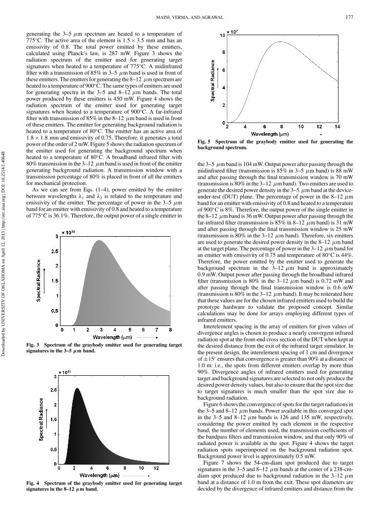
generating the 3–5 �m spectrum are heated to a temperature of775C. The active area of the element is 1:5 � 3:5 mm and has anemissivity of 0.8. The total power emitted by these emitters,calculated using Planck’s law, is 287 mW. Figure 3 shows theradiation spectrum of the emitter used for generating targetsignatures when heated to a temperature of 775C. A midinfraredfilter with a transmission of 85% in 3–5 �m band is used in front ofthese emitters. The emitters for generating the 8–12 �m spectrum areheated to a temperature of 900C. The same types of emitters are usedfor generating spectra in the 3–5 and 8–12 �m bands. The totalpower produced by these emitters is 450 mW. Figure 4 shows theradiation spectrum of the emitter used for generating targetsignatures when heated to a temperature of 900C. A far-infraredfilter with transmission of 85% in the 8–12 �m band is used in frontof these emitters. The emitter for generating background radiation isheated to a temperature of 80C. The emitter has an active area of1:8 � 1:8 mm and emissivity of 0.75. Therefore, it generates a totalpower of the order of 2mW. Figure 5 shows the radiation spectrum ofthe emitter used for generating the background spectrum whenheated to a temperature of 80C. A broadband infrared filter with80% transmission in the 3–12 �m band is used in front of the emittergenerating background radiation. A transmission window with atransmission percentage of 80% is placed in front of all the emittersfor mechanical protection.
As we can see from Eqs. (1–4), power emitted by the emitterbetween wavelengths �1 and �2 is related to the temperature andemissivity of the emitter. The percentage of power in the 3–5 �mband for an emitter with emissivity of 0.8 and heated to a temperatureof 775C is 36.1%. Therefore, the output power of a single emitter in
the 3–5 �m band is 104mW.Output power after passing through themidinfrared filter (transmission is 85% in 3–5 �m band) is 88 mWand after passing through the final transmission window is 70 mW(transmission is 80% in the 3–12 �m band). Two emitters are used togenerate the desired power density in the 3–5 �m band at the device-under-test (DUT) plane. The percentage of power in the 8–12 �mband for an emitter with emissivity of 0.8 and heated to a temperatureof 900C is 8%. Therefore, the output power of the single emitter inthe 8–12 �m band is 36mW.Output power after passing through thefar-infrared filter (transmission is 85% in 8–12 �m band) is 31 mWand after passing through the final transmission window is 25 mW(transmission is 80% in the 3–12 �m band). Therefore, six emittersare used to generate the desired power density in the 8–12 �m bandat the target plane. The percentage of power in the 3–12 �m band foran emitter with emissivity of 0.75 and temperature of 80C is 44%.Therefore, the power emitted by the emitter used to generate thebackground spectrum in the 3–12 �m band is approximately0.9 mW. Output power after passing through the broadband infraredfilter (transmission is 80% in the 3–12 �m band) is 0.72 mW andafter passing through the final transmission window is 0.6 mW(transmission is 80% in the 3–12 �m band). It may be reiterated herethat these values are for the chosen infrared emitters used to build theprototype hardware to validate the proposed concept. Similarcalculations may be done for arrays employing different types ofinfrared emitters.
Interelement spacing in the array of emitters for given values ofdivergence angles is chosen to produce a nearly convergent infraredradiation spot at the front-end cross section of the DUTwhen kept atthe desired distance from the exit of the infrared target simulator. Inthe present design, the interelement spacing of 1 cm and divergenceof�15 ensures that convergence is greater than 90% at a distance of1.0 m: i.e., the spots from different emitters overlap by more than90%. Divergence angles of infrared emitters used for generatingtarget and background signatures are selected to not only produce thedesired power density values, but also to ensure that the spot size dueto target signatures is much smaller than the spot size due tobackground radiation.
Figure 6 shows the convergence of spots for the target radiations inthe 3–5 and 8–12 �m bands. Power available in this converged spotin the 3–5 and 8–12 �m bands is 126 and 135 mW, respectively,considering the power emitted by each element in the respectiveband, the number of elements used, the transmission coefficients ofthe bandpass filters and transmission window, and that only 90% ofradiated power is available in the spot. Figure 4 shows the targetradiation spots superimposed on the background radiation spot.Background power level is approximately 0.5 mW.
Figure 7 shows the 54-cm-diam spot produced due to targetsignatures in the 3–5 and 8–12 �m bands at the center of a 238-cm-diam spot produced due to background radiation in the 3–12 �mband at a distance of 1.0 m from the exit. These spot diameters aredecided by the divergence of infrared emitters and distance from the
Fig. 3 Spectrum of the graybody emitter used for generating target
signatures in the 3–5 �m band.
Fig. 4 Spectrum of the graybody emitter used for generating target
signatures in the 8–12 �m band.
Fig. 5 Spectrum of the graybody emitter used for generating the
background spectrum.
MAINI, VERMA, AND AGRAWAL 177
Dow
nloa
ded
by U
NIV
ER
SIT
Y O
F O
KL
AH
OM
A o
n A
pril
12, 2
013
| http
://ar
c.ai
aa.o
rg |
DO
I: 1
0.25
14/1
.496
48
exit. For divergence of�15 and 1.0 m distance, it would be 54 cm(2 � tan 15 � 100 cm), and for divergence of �50, it would be238 cm (2 � tan 50 � 100 cm). For a spot diameter of 54 cm andpower levels of 126 and 135 mW in the 3–5 and 8–12 �m bands,respectively, the power density in the 3–5 and 8–12 �m bands isapproximately 56 �W=cm2 each. For a spot diameter of 238 cm anda power level of 0.5 mW in background radiation, power density inbackground radiation is approximately 12 nW=cm2 each.
The parameter control module shown in Fig. 2 comprises anembedded controller interfaced with the keypad and display anddesigned to generate control signals for the two-dimensional array.The prototype hardware employs a 128 � 128 liquid crystal displayand a 3 � 3 matrix keypad. Any other suitable display and keypadcould be used instead. The embedded controller can be programmedto produce the desired operational modes. In the proposed design,four operational modes are programmed. These include 1) targetsignatures in the 3–5 �m band without background, 2) targetsignatures in the 3–5 �m band with background, 3) target signaturesin the 3–5 and 8–12 �m bands without background, and 4) targetsignatures in the 3–5 and 8–12 �m bandswith background.Modes 1and 2 are used for testing single-color infrared-guided missiles, andmodes 3 and 4 are used for testing two-color infrared-guidedmissiles. Based on the operationalmode selected through the keypad,the embedded controller generates a set of commands to operate acombination of controlled analog switches to allow the desiredvalues of dc voltage to be applied to relevant infrared emitters.Desired dc voltages are generated by voltage regulator circuits thatare part of the drive electronicsmodule. The drive electronicsmodulealso comprises buffer circuits to provide the required drive current tothe control inputs of analog switches.
Design Using Array of Infrared Light-Emitting Diodes
Another possible approach to design an infrared target simulatorfor testing the nonimaging types of infrared-guided missiles is to usean array ofmidinfrared LEDs (with different LEDs driven to generateinfrared radiation in the specified wavelength spectrum) and acentrally located graybody emitter to generate the static background.
Each LED in the array generates a specific wavelength. DifferentLEDs in the array are chosen to have staggered peak emissionwavelength over the wavelength region of interest. Typical FWHM(full width at half-maximum) linewidth of output radiation fromthese LEDs is in the range of 10 to 20% of the peak emissionwavelength. Overlapping beams from these LEDs are combined toproduce the desired wavelength spectrum. The LED-based designhas two distinct advantages.
1) It does not require bandpass filters to get the desired spectralshape.
2)Output power from eachLED, and therefore the total power, canbe conveniently controlled by changing the input drive current,which allows the designer to build a device that can test the weaponover its full operational range.
Presently, these midinfrared LEDs are available only in the1:6–7:0 �m band. Therefore, the proposed LED-based design isapplicable to infrared target simulators for testing single-colorinfrared-guided missiles.
A number of manufacturers offer midinfrared LEDs. One such setof midinfrared LEDs comprising LED-30SC, LED-34SC, LED-36SC, LED-38SC, LED-42SC, and LED-47SC (Scitec), withcorresponding peak emission wavelengths at 3.0, 3.4, 3.6, 3.8, 4.2,and 4:7 �m, could be used to generate the desired spectral output in3–5 �m band for testing single-color infrared-guided missiles.These LEDs have a built-in lens that reduces the divergence of theemitted radiation. Some manufacturers offer midinfrared LEDs withbuilt-in parabolic reflectors for the same purpose.
Figure 8 shows the block schematic arrangement depicting themidinfrared LED-based concept. A heterogeneous two-dimensionalarray of midinfrared LEDs and a single graybody emitter arethe foundation of the system.Othermajor building blocks include theparameter controlmodule and drive electronicsmodule to operate thearray of emitters and the protective optical window. The two-dimensional array of infrared emitters is used to generate the targetsignatures and background spectrum in the 3–5 �m band. Thoughthe hardware built to validate the proposed design concept isconfigured around a 4 � 4 array of midinfrared LEDs and onegraybody emitter, the concept is equally valid for a two-dimensionalarray of any size, as long as it meets the requirement of producing therequired power density in the given spectral band with the desiredspectral shape. Of the 16 midinfrared LEDs, there is one each of thetypes LED-30SC, LED-34SC, LED-36SC, and LED-38SC. Thereare four LEDs of the type LED-42SC and eight LEDs of the typeLED-47SC. The number of elements producing 3–5 �m radiationdepends upon the desired magnitudes of infrared radiation in the3–5 �m band and the power level available from individualelements. The number of elements of each type in the array depends
Fig. 8 Block schematic arrangement of design concept using array of
midinfrared LEDs.
Fig. 6 Diagram showing convergence of individual radiation spots of
the target spectrum.
Fig. 7 Diagram showing radiation spots due to infrared signatures of
target and background.
178 MAINI, VERMA, AND AGRAWAL
Dow
nloa
ded
by U
NIV
ER
SIT
Y O
F O
KL
AH
OM
A o
n A
pril
12, 2
013
| http
://ar
c.ai
aa.o
rg |
DO
I: 1
0.25
14/1
.496
48
upon the continuous-wave power level available from individualLEDs of different peak emission wavelengths and the desiredspectral shape.
Midinfrared LEDs are used without any bandpass filters, as theradiation from each individual LED has narrow linewidth around thepeak wavelength. Figure 9 shows the radiated spectrum in the case ofmidinfrared LEDs chosen to build the prototype hardware. Aninfrared emitter used for generating background is used without aparabolic reflector, and a bandpass filter is placed in front of it, forreasons explained in the case of the first design. The peak of spectraloutput in the case of the graybody infrared emitter occurs at awavelength dependent upon the temperature to which it is heated,which depends upon the dc voltage applied to the chosen type ofsolid-state infrared emitter. In the case ofmidinfrared LEDs, the drivecurrent determines the output power. The LEDs chosen to generatethe 3–5 �m band have FWHM of�20 without the lens and �10with the lens. The graybody emitter used for generating thebackground has divergence of �50. A midinfrared bandpass filterplaced in front of the background emitter has 80% transmission in the3–5 �m band. TheLEDs produce a radiation spot diameter of 0.35m(area 0:1 m2) for target signatures, and the graybody emitter
produces a radiation spot diameter of 2.4 m (area� 4:5 m2) forbackground at a DUT distance of 1.0 m.
The total power emitted by the LEDs is proportional to the drivecurrent through them. The hardware developed has the option tochoose from two different power levels for testing the missile at twodifferent operational ranges. The total power in the radiationsimulating target signatures is approximately 300 �W in one of thesettings and 100 �W in the other setting. The second power setting isgenerated by changing the drive currents through the midinfraredLEDs. This current change is done by changing the switch position ofthe hardware. Power in background signatures is 0.6 mW in a spotdiameter of 2.4 m. This results in background power density of13:5 nW=cm2 and a settable target signature power density ofapproximately 312 and 104 nW=cm2.
The parameter control module is similar to the one describedearlier in the case of the first design. Controlled analog switches inthis case are the single-pole/double-throw type to allow selection oftwo different power densities of the target signatures throughdifferent current drives. The switch used to select the background isof the simple on/off type. Different combinations of keys on thekeypad can be used to select the desired operational mode. The
Fig. 9 Spectral outputs of different midinfrared LEDs chosen to build hardware.
MAINI, VERMA, AND AGRAWAL 179
Dow
nloa
ded
by U
NIV
ER
SIT
Y O
F O
KL
AH
OM
A o
n A
pril
12, 2
013
| http
://ar
c.ai
aa.o
rg |
DO
I: 1
0.25
14/1
.496
48
keypad and the displaymodule used to build the hardware to validatethe proposed design concept are the same as those used in the case ofthe first design.
Hardware Evaluation
The prototype hardware built to validate the proposed conceptswas evaluated for various performance parameters, which mainlyinclude spectral distribution and power density.
Graybody-Emitter-Based Design
Figure 10 shows the infrared radiation spectrum for the operationalmode generating target signatures in the 3–5 �m band withoutbackground infrared radiation. The measured power density is56:5 �W=cm2. Figure 11 shows the infrared radiation spectrumgenerated for the operationalmode generating target signatures in the3–5 �m band with background infrared radiation. The measured
Fig. 12 Target infrared radiation spectrum in the 3–5 and 8–12 �mbands without background radiation.
Fig. 13 Target infrared radiation spectrum in the 3–5 and 8–12 �mbands with background radiation.
0
50
100
150
200
250
300
350
2.4 2.9 3.4 3.9 4.4 4.9 5.4 5.9Wavelength (µm)
Inte
nsi
ty (A
rb.u
n.)
3 to 5 micron spectrum
Fig. 14 Target infrared radiation spectrum in the 3–5 �m band
without background radiation.
Fig. 15 Target infrared radiation spectrum in the 3–5 �m band with
background radiation.
Fig. 11 Target infrared radiation spectrum in the 3–5 �m band withbackground radiation.
Fig. 10 Target infrared radiation spectrum in the 3–5 �m band
without background radiation.
180 MAINI, VERMA, AND AGRAWAL
Dow
nloa
ded
by U
NIV
ER
SIT
Y O
F O
KL
AH
OM
A o
n A
pril
12, 2
013
| http
://ar
c.ai
aa.o
rg |
DO
I: 1
0.25
14/1
.496
48
power density is 56 �W=cm2 in the case of the 3–5 �m band and14 nW=cm2 in the case of background radiation. Figure 12 shows theinfrared radiation spectrum for the operational mode generatingtarget signatures in the 3–5 and 8–12 �m bands without backgroundinfrared radiation. The measured power density is 55:5 �W=cm2 inthe case of the 3–5 �m band and 54:8 �W=cm2 in the case of the8–12 �m band. Figure 13 shows the infrared radiation spectrum forthe operational mode generating target signatures in the 3–5 and8–12 �m bands with background infrared radiation. The measuredpower density is 54:5 �W=cm2 in the case of the 3–5 �m band,54:8 �W=cm2 in the case of the 8–12 �m band, and 14 nW=cm2 inthe case of background radiation. The measured values of powerdensity in all cases closely match with the estimated values.
Midinfrared-LED-Based Design
Figures 14 and 15 show the spectral distribution of the targetsignatures in the 3–5 �m band without and with backgroundradiation, respectively. The measured intensity versus wavelengthcurve closely matches with the estimated one. Measured powerdensity in the 3–5 �m band is 310 nW=cm2 for the first setting,which closelymatches with theoretical values. The power density forthe second setting was measured to be 95 nW=cm2, which againmatches with the theoretical estimate. The prototype hardware in thetwo caseswas used to perform lock-on sensitivity check on the seekerhead of a single-color infrared-guided missile of foreign origin.Figure 16 shows the test setup.
Conclusions
Two design approaches to building an infrared target simulator forperforming a preflight serviceability check on both single-color andtwo-color infrared-guided missiles without the need for disassem-bling them from the launch platform are presented in this paper. Theresulting hardware is intended to be portable, which is an essentialrequirement for carrying out serviceability checks in strap-on con-dition. In addition, the proposed designs generate the desired infraredsignatures of the target in the presence of background noise, thussimulating the real battlefield conditions and overcoming limitations
of similar portable devices that are available commercially ordiscussed in literature.
References
[1] Rao, G. A., and Mahulikar, S. P., “New Criterion for AircraftSusceptibility to Infrared Homing Missiles,” Aerospace Science and
Technology, Vol. 9, No. 8, Nov. 2005, pp. 701–712.doi:10.1016/j.ast.2005.07.005
[2] Pollock, D. H., “Countermeasures Systems,” The Infrared Electro-
Optical Systems Handbook, 1st ed., Vol. 7, SPIE, Bellingham, WA,1993, pp. 162–165.
[3] Sturlesi, D., and Pinsky, E., “Target Scene Generator (TSG) for InfraredSeeker Evaluation,” Technologies for Synthetic Environments:
Hardware-in-the-Loop Testing II, Proceedings of SPIE, Vol. 3084,SPIE, Bellingham, WA, July 1997, pp. 111–119.doi:10.1117/12.280941
[4] Rao, G. A., and Mahulikar, S. P., “Effect of Atmospheric Transmissionand Radiance on Aircraft Infrared Signatures,” Journal of Aircraft,Vol. 42, No. 4, July–Aug. 2005, pp. 1064–1054.doi:10.2514/1.7515
[5] Bell, W. A., and Glasgow, B. B., “Impact of Advances in ImagingInfrared Detectors on Anti-Aircraft Missile Performance,” Infrared
Imaging Systems: Design, Analysis, Modeling, and Testing X,Proceedings of SPIE, Vol. 3701, SPIE, Bellingham, WA, April 1999,pp. 244–253.doi:10.1117/12.352977
[6] Longair, M. S., “Black-body Radiation up to 1895,” Theoretical
Concepts in Physics: An Alternative View of Theoretical Reasoning in