Task Transfer via Collaborative Manipulation for Insertion Assembly Klas Kronander 1 , Etienne Burdet 2 and Aude Billard 1 Abstract—Insertion tasks are a major difficulty for autom- atizing manufacturing processes. The bench-mark problem in this category, peg-in-hole, is representative of the challenges that arise in uncertain assembly operations. Humans can carry out this task with ease, even in absence of visual information, relying on haptic and tactile sensing to align the peg with the hole. No generic control approach exist that can reproduce this capability in robots. In this work, we propose a system that allows to transfer this skill to a robot through collaborative task executions. The robot learns from these executions by monitoring its pose and sensed force information and encoding it as a multivariate probability distribution. This distribution is then used to realize an active correction strategy allowing the robot to execute the task autonomously. The approach is validated through a comparative study of peg-in-hole insertion using five different adaptation schemes. The results indicate a significant advantage of the learned model compared to blind random search and insertion without adaptation. I. INTRODUCTION The difficulty of the peg-in-hole task and its importance for assembly operations in the manufacturing industry are well documented in literature [1]. If the pose of the parts can be tracked with negligible inaccuracy, the problem can be solved by generating trajectories based on the geometry of the parts [2]. This method fails in the common case where the uncertainty of the pose estimate or accuracy of control is significantly larger than the clearance. Humans can carry out the peg-in-hole task with or without visual feedback by relying on haptic feedback for completing the task. By feeling the interaction between the peg and the hole, humans are able to instantly adapt the pose of the peg to complete the task. It would be highly desirable to transfer this skill to robots. In this work, we take a step in this direction and propose a methodology for transferring task-specific insertion- skills to robots. Our approach is based on Learning from Demonstration (LfD) [3]–[5], and uses data recorded from collaborative task executions, see Fig. 1, to learn a compliance model for a specific insertion task. Reinforcement learning has been employed in [6], [7] for gradually acquiring a map from sensed force to corrective velocity for peg-in-hole insertion. In reinforcement learning, the robot is evaluating its own attempts at the task using a task-specific cost function. A general problem with applying reinforcement learning to real robots is that a large amount of trials is usually needed for learning the task. Both [6] 1 Klas Kronander and Aude Billard are with the Learning Algorithms and Systems Laboratory, School of Engineering, Swiss Federal Institute of Technology Lausanne. {klas.kronander}{aude.billard} at epfl.ch 2 Etienne Burdet is with the Department of Bioengineering, Imperial College of Science, Technology and Medicine, London. e.burdet at imperial.ac.uk Fig. 1. Left: The robot has found the hole but the peg is jammed due to incorrect orientation. The teacher grasps the robot to correct the orientation. Middle: The teacher has corrected the orientation. Right: As the teacher releases the robot, it automatically completes the insertion. and [7] reported hundreds of trials before the task had been successfully learned. For interaction tasks, this is especially problematic since hazardous contact forces can arise during the trials [6]. An easily implementable approach to peg-in-hole is to use slight random movements or oscillations of the reference trajectory [8]. With this approach, the idea is that the mis- alignment will eventually be compensated by pseudo-random movements applied to the end-effector. To limit the contact forces that will obviously arise when the reference is adapted in the wrong direction, it is necessary to combine this approach with a lower level compliance. Instead of random search, the use of predetermined search patterns has also been explored [9], [10]. Inherently compliant actuation was exploited to allow aggressive search strategies in [11]. These techniques do not require a force sensor but are often time consuming and can potentially cause high contact forces, making them unsuitable for many assembly operations. In contrast to the reinforcement learning and random ap- proaches, we take advantage of the fact that humans can solve the peg-in-hole task very easily, and learn from data collected in collaborative task executions. Conceptually, our approach is similar to [12] and [13], where it was proposed to use multilayer neural nets mapping sensed end-effector force to desired velocity as a representation of non-linear compliance. In these works, the availability of a sufficiently large noise- free training set was assumed. In contrast, we integrate the data-collection as a natural step in our approach, where the teacher helps the robot to complete the insertion by guiding it physically. We model the probability distribution between sensed wrench and corrective velocity, which allows us to combine the advantages of a learned compliance model [13] and random search [8]. This is achieved by sampling the corrective velocity from a distribution which is conditioned on the sensed wrench. We evaluate our approach in a series of peg in hole experiments with the Barrett WAM arm. Five different adap- tation schemes are compared: A) no adaptation B) Gaussian
Transcript
Task Transfer via Collaborative Manipulation for Insertion Assembly
Klas Kronander1, Etienne Burdet2 and Aude Billard1
Abstract—Insertion tasks are a major difficulty for autom-atizing manufacturing processes. The bench-mark problem inthis category, peg-in-hole, is representative of the challengesthat arise in uncertain assembly operations. Humans can carryout this task with ease, even in absence of visual information,relying on haptic and tactile sensing to align the peg with thehole. No generic control approach exist that can reproduce thiscapability in robots. In this work, we propose a system thatallows to transfer this skill to a robot through collaborative taskexecutions. The robot learns from these executions by monitoringits pose and sensed force information and encoding it as amultivariate probability distribution. This distribution is thenused to realize an active correction strategy allowing the robotto execute the task autonomously. The approach is validatedthrough a comparative study of peg-in-hole insertion using fivedifferent adaptation schemes. The results indicate a significantadvantage of the learned model compared to blind random searchand insertion without adaptation.
I. INTRODUCTION
The difficulty of the peg-in-hole task and its importance forassembly operations in the manufacturing industry are welldocumented in literature [1]. If the pose of the parts canbe tracked with negligible inaccuracy, the problem can besolved by generating trajectories based on the geometry ofthe parts [2]. This method fails in the common case wherethe uncertainty of the pose estimate or accuracy of controlis significantly larger than the clearance. Humans can carryout the peg-in-hole task with or without visual feedback byrelying on haptic feedback for completing the task. By feelingthe interaction between the peg and the hole, humans areable to instantly adapt the pose of the peg to complete thetask. It would be highly desirable to transfer this skill torobots. In this work, we take a step in this direction andpropose a methodology for transferring task-specific insertion-skills to robots. Our approach is based on Learning fromDemonstration (LfD) [3]–[5], and uses data recorded fromcollaborative task executions, see Fig. 1, to learn a compliancemodel for a specific insertion task.
Reinforcement learning has been employed in [6], [7] forgradually acquiring a map from sensed force to correctivevelocity for peg-in-hole insertion. In reinforcement learning,the robot is evaluating its own attempts at the task using atask-specific cost function. A general problem with applyingreinforcement learning to real robots is that a large amountof trials is usually needed for learning the task. Both [6]
1 Klas Kronander and Aude Billard are with the Learning Algorithmsand Systems Laboratory, School of Engineering, Swiss Federal Institute ofTechnology Lausanne. {klas.kronander}{aude.billard} atepfl.ch
2 Etienne Burdet is with the Department of Bioengineering, ImperialCollege of Science, Technology and Medicine, London. e.burdet atimperial.ac.uk
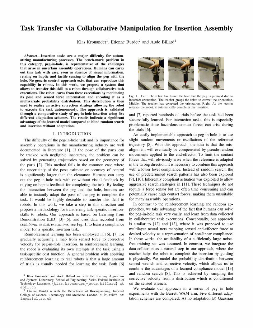
Fig. 1. Left: The robot has found the hole but the peg is jammed due toincorrect orientation. The teacher grasps the robot to correct the orientation.Middle: The teacher has corrected the orientation. Right: As the teacherreleases the robot, it automatically completes the insertion.
and [7] reported hundreds of trials before the task had beensuccessfully learned. For interaction tasks, this is especiallyproblematic since hazardous contact forces can arise duringthe trials [6].
An easily implementable approach to peg-in-hole is to useslight random movements or oscillations of the referencetrajectory [8]. With this approach, the idea is that the mis-alignment will eventually be compensated by pseudo-randommovements applied to the end-effector. To limit the contactforces that will obviously arise when the reference is adaptedin the wrong direction, it is necessary to combine this approachwith a lower level compliance. Instead of random search, theuse of predetermined search patterns has also been explored[9], [10]. Inherently compliant actuation was exploited to allowaggressive search strategies in [11]. These techniques do notrequire a force sensor but are often time consuming and canpotentially cause high contact forces, making them unsuitablefor many assembly operations.
In contrast to the reinforcement learning and random ap-proaches, we take advantage of the fact that humans can solvethe peg-in-hole task very easily, and learn from data collectedin collaborative task executions. Conceptually, our approachis similar to [12] and [13], where it was proposed to usemultilayer neural nets mapping sensed end-effector force todesired velocity as a representation of non-linear compliance.In these works, the availability of a sufficiently large noise-free training set was assumed. In contrast, we integrate thedata-collection as a natural step in our approach, where theteacher helps the robot to complete the insertion by guidingit physically. We model the probability distribution betweensensed wrench and corrective velocity, which allows us tocombine the advantages of a learned compliance model [13]and random search [8]. This is achieved by sampling thecorrective velocity from a distribution which is conditionedon the sensed wrench.
We evaluate our approach in a series of peg in holeexperiments with the Barrett WAM arm. Five different adap-tation schemes are compared: A) no adaptation B) Gaussian
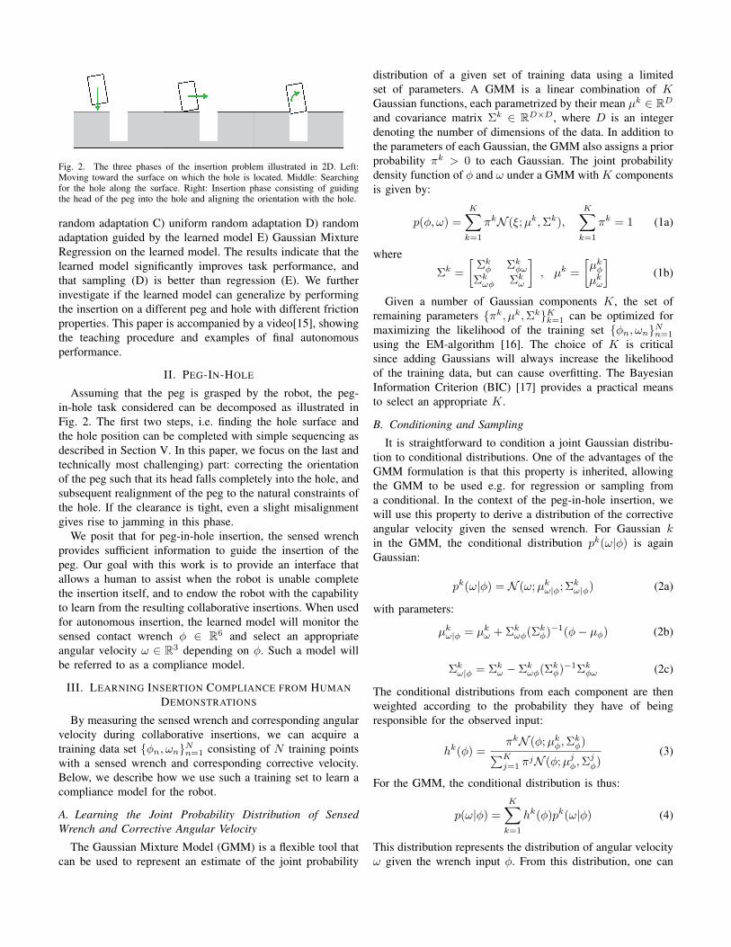
Fig. 2. The three phases of the insertion problem illustrated in 2D. Left:Moving toward the surface on which the hole is located. Middle: Searchingfor the hole along the surface. Right: Insertion phase consisting of guidingthe head of the peg into the hole and aligning the orientation with the hole.
random adaptation C) uniform random adaptation D) randomadaptation guided by the learned model E) Gaussian MixtureRegression on the learned model. The results indicate that thelearned model significantly improves task performance, andthat sampling (D) is better than regression (E). We furtherinvestigate if the learned model can generalize by performingthe insertion on a different peg and hole with different frictionproperties. This paper is accompanied by a video[15], showingthe teaching procedure and examples of final autonomousperformance.
II. PEG-IN-HOLE
Assuming that the peg is grasped by the robot, the peg-in-hole task considered can be decomposed as illustrated inFig. 2. The first two steps, i.e. finding the hole surface andthe hole position can be completed with simple sequencing asdescribed in Section V. In this paper, we focus on the last andtechnically most challenging) part: correcting the orientationof the peg such that its head falls completely into the hole, andsubsequent realignment of the peg to the natural constraints ofthe hole. If the clearance is tight, even a slight misalignmentgives rise to jamming in this phase.
We posit that for peg-in-hole insertion, the sensed wrenchprovides sufficient information to guide the insertion of thepeg. Our goal with this work is to provide an interface thatallows a human to assist when the robot is unable completethe insertion itself, and to endow the robot with the capabilityto learn from the resulting collaborative insertions. When usedfor autonomous insertion, the learned model will monitor thesensed contact wrench φ ∈ R6 and select an appropriateangular velocity ω ∈ R3 depending on φ. Such a model willbe referred to as a compliance model.
III. LEARNING INSERTION COMPLIANCE FROM HUMANDEMONSTRATIONS
By measuring the sensed wrench and corresponding angularvelocity during collaborative insertions, we can acquire atraining data set {φn, ωn}Nn=1 consisting of N training pointswith a sensed wrench and corresponding corrective velocity.Below, we describe how we use such a training set to learn acompliance model for the robot.
A. Learning the Joint Probability Distribution of SensedWrench and Corrective Angular Velocity
The Gaussian Mixture Model (GMM) is a flexible tool thatcan be used to represent an estimate of the joint probability
distribution of a given set of training data using a limitedset of parameters. A GMM is a linear combination of KGaussian functions, each parametrized by their mean µk ∈ RDand covariance matrix Σk ∈ RD×D, where D is an integerdenoting the number of dimensions of the data. In addition tothe parameters of each Gaussian, the GMM also assigns a priorprobability πk > 0 to each Gaussian. The joint probabilitydensity function of φ and ω under a GMM with K componentsis given by:
p(φ, ω) =
K∑k=1
πkN (ξ;µk,Σk),
K∑k=1
πk = 1 (1a)
where
Σk =
[Σkφ ΣkφωΣkωφ Σkω
], µk =
[µkφµkω
](1b)
Given a number of Gaussian components K, the set ofremaining parameters {πk, µk,Σk}Kk=1 can be optimized formaximizing the likelihood of the training set {φn, ωn}Nn=1
using the EM-algorithm [16]. The choice of K is criticalsince adding Gaussians will always increase the likelihoodof the training data, but can cause overfitting. The BayesianInformation Criterion (BIC) [17] provides a practical meansto select an appropriate K.
B. Conditioning and Sampling
It is straightforward to condition a joint Gaussian distribu-tion to conditional distributions. One of the advantages of theGMM formulation is that this property is inherited, allowingthe GMM to be used e.g. for regression or sampling froma conditional. In the context of the peg-in-hole insertion, wewill use this property to derive a distribution of the correctiveangular velocity given the sensed wrench. For Gaussian kin the GMM, the conditional distribution pk(ω|φ) is againGaussian:
pk(ω|φ) = N (ω;µkω|φ; Σkω|φ) (2a)
with parameters:
µkω|φ = µkω + Σkωφ(Σkφ)−1(φ− µφ) (2b)
Σkω|φ = Σkω − Σkωφ(Σkφ)−1Σkφω (2c)
The conditional distributions from each component are thenweighted according to the probability they have of beingresponsible for the observed input:
hk(φ) =πkN (φ;µkφ,Σ
kφ)∑K
j=1 πjN (φ;µjφ,Σ
jφ)
(3)
For the GMM, the conditional distribution is thus:
p(ω|φ) =
K∑k=1
hk(φ)pk(ω|φ) (4)
This distribution represents the distribution of angular velocityω given the wrench input φ. From this distribution, one can
acquire a functional relationship from φ to ω by taking the ex-pectation of the conditional: ω̂ = E{p(ω|φ)}. This is a widelyused technique in LfD called Gaussian Mixture Regression(GMR). Alternatively, we can sample from this distribution,ω̂ ∼ p(ω|φ), which results in a random search which is guidedby the learned model. Both of these alternatives are comparedin Section VI.
IV. CONTROL ARCHITECTURE
Our approach for deriving a reactive behavior mappingsensed wrench to corrective angular velocity is based onnoisy training data. It is thus possible, regardless if samplingor regression is used, that incorrect angular velocities willbe chosen. To avoid hazardous build up of contact forceswhen incorrect velocities are applied, we therefore use acontroller with a lower level compliance for executing thereference trajectory, which is modified online based on thesensed wrench. The compliant control law consists of feedbackcontrol on the Cartesian error x̃ and its time derivative ˙̃x. TheCartesian feedback control is then converted to joint torquesby multiplication of the transposed Jacobian J(q). We alsouse a feedforward term g(q) to compensate for gravity atconfiguration q. The control torques are thus:
τ = JT (−Kx̃−D ˙̃x) + g(q) (5)
where K,D ∈ R6×6 are symmetric positive definite stiffnessand damping matrices. Given reference and actual positionspr, p ∈ R3 and orientations Rr, R ∈ R3×3, we define theCartesian error term as:
x̃ =
[p− prψ
], ψ = angleaxis
(RTRr
)(6)
where angleaxis(R∗) denotes the operator1 that computes theangle-axis representation corresponding to a rotation matrixR∗. This error representation eliminates representational sin-gularities and ensures physical consistency between the errorand corrective wrench [18]. The stiffness matrix was chosendiagonal, with translational stiffness kp = 400 N/m alongall three axes and rotational stiffness ko = 2 Nm/rad aroundthe three axes: K = diag(kp, kp, kp, ko, ko, ko). The dampingwas selected diagonal with a constant damping ratio of 2, i.e.Dij = 2
√Kij i, j ∈ 1 . . . 6, where Dij denotes the element
at row i and column j of D. A block diagram of the controlarchitechture is shown in Fig. 3.
V. EXPERIMENTAL SETUP
To evaluate the proposed system, several experiments withdifferent adaptation schemes were carried out on a 7-degree-of-freedom Barrett WAM as seen in Fig. 4. Two sets of pegsand holes were used: 1) steel peg with diameter 15.94mm,steel hole with diameter 15.98mm and 2) wooden peg withdiameter 16.5mm and rubber hole with diameter 18mm. Thedifferent pegs and holes can be seen in Fig. 6
1The axis ψ‖ψ‖ is the eigenvector of R∗ that has eigenvalue λ = 1. The
angle θ = ‖ψ‖ is found by solving 1 + 2 cos(θ) = tr(R∗).
Robot
Gravity
compensation
+
Forward
kinematics
Preparation
Demonstration
Autonomous
Insertion
Cartesian error
Impedance control:
Joint
angles
Sensed
wrench
Cart.
pos.
Cart.
orient.
Reference
Cart.
pos./orient.
Kinematic
Jacobian
Cart.
error
Joint
torque
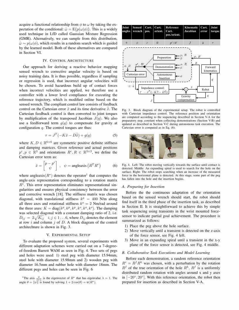
Fig. 3. Block diagram of the experimental setup. The robot is controlledwith Cartesian impedance control. The reference position and orientationare computed according to the sequencing described in Section V-A for thepreparatory step, constant when collecting demonstrations (Section V-B) andupdated as described in Section V-C during autonomous task execution. TheCartesian error is computed as in Eq. (6).
Fig. 4. Left: The robot moving vertically towards the surface until contact isdetected. Middle: An expanding spiral is used to search for the hole on thesurface. Right: The robot stops searching when an increase of the measuredforce in the horizontal plane is detected. At this stage, some part of the peghas fallen into the hole and the insertion begins.
A. Preparing for Insertion
Before the the continuous adaptation of the orientationbased on the sensed wrench should start, the robot shouldfind itself in the third phase of the insertion task, as describedin Section II. It is straightforward to achieve this by simpletask sequencing using transients in the wrist mounted force-sensor to indicate partial goal achievement. The procedure issummarized as follows:
1) Place the peg above the hole surface.2) Move vertically until a transient is detected on the z-axis
of the force sensor, see Fig. 4 left.3) Move in an expanding spiral until a transient in the x-y
plane of the force sensor is detected, see Fig. 4 middle.
B. Collaborative Task Executions and Model Learning
Before each demonstration, a random reference orientationRr = RfRh was chosen, with a perturbation by the rotationRf of the true orientation of the hole Rh. Rf is a uniformlydistributed random rotation with angles around x and y axesin [−20◦, 20◦]. With this reference orientation, the robot thenprepared for insertion as described in Section V-A.
Once the robot had found the hole, the stiffness was reducedto kp = 100 N/m and ko = 0.5 Nm/rad, allowing the teacherto correct the orientation of the end-effector. The teacherthen helped the robot to complete the insertion by physicallyguiding it, see Fig. 1 and the accompanying video[15]. Notethat during this phase, the robot is still actively controlled andby itself trying to push the peg into the hole. The insertionis hence a collaborative effort, where the human is correctingthe orientation of the peg while the robot is applying a smalldownward force. The sensed wrench φ was recorded alongwith the angular velocity ω at a frequency of 100 Hz during15 such collaborative insertions.
GMMs with numbers of Gaussians ranging from 1 to20 were then trained using EM on the collected training.Evaluation using BIC on the trained models favoured a GMMwith 6 components, which was therefore selected as the modelfor experimental evaluation.
To compare our approach with random search that does nottake the sensed wrench into account, we used two controllers,sampling either from a Gaussian or uniform distribution. Tomake the comparison fair, we ensured that the two randomsearch controllers were somewhat informed about the task byadapting their parameters according to the observed data. Themean of the Gaussian was chosen to µNω = 0 and the covari-ance matrix ΣNω was computed as the empirical covariancematrix of the collected samples of angular velocities.
The uniform distribution was independent in each com-ponent j = 1, 2, 3 of ω = [ω1, ω2, ω3]T . Bounds for eachcomponent ωj were selected as the minimum value aj andmaximum value bj for that component in the centered trainingdata. In the following, we denote the joint distribution of thethree components by U(a, b).
C. Autonomous Task Execution
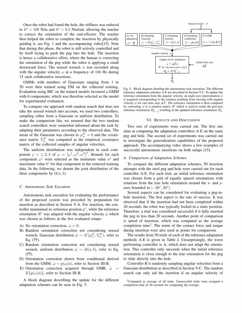
Autonomous task execution for evaluating the performanceof the proposed system was preceded by preparation forinsertion as described in Section V-A. For insertion, the con-troller maintained its reference position pr, while the referenceorientation Rr was adapted with the angular velocity ω̂ whichwas chosen as follows in the five evaluated setups:
A) No orientation correction, ω̂ = 0.B) Random orientation correction not considering sensed
wrench, Gaussian distribution ω̂ ∼ N (µNω ,ΣNω ), refer to
Eq. (??).C) Random orientation correction not considering sensed
wrench, uniform distribution ω̂ ∼ U(a, b), refer to Eq.(??).
D) Orientation correction drawn from conditional derivedfrom the GMM, ω̂ ∼ p(ω|φ), refer to Section III-B.
E) Orientation correction acquired through GMR, ω̂ =E{p(ω|φ)}, refer to Section III-B.
A block diagram describing the update for the differentadaptation schemes can be seen in Fig. 5.
D) Sampling
conditional
A) No
adaptation
B) Sampling
Gaussian
E) GMR
Update of ref. orientationUpdate time step
C) Sampling
uniform
Sensed wrench
Angular velocity
Fig. 5. Block diagram detailing the autonomous task execution. The differentreference adaptation schemes A-E are described in Section V-C. To update thereference orientation from the angular velocity, an angle axis representation ψis acquired corresponding to the rotation resulting from moving with angularvelocity ω̂ for one time step ∆T . The reference orientation is then computedby converting ψ to a rotation matrix R′ which is used to rotate the previousreference orientation Rrk−1 resulting in the updated reference orientation Rrk .
VI. RESULTS AND DISCUSSION
Two sets of experiments were carried out. The first oneaims at comparing the adaptation controllers A-E on the samepeg and hole. The second set of experiments was carried outto investigate the generalization capabilities of the proposedapproach. The accompanying video shows a few examples ofsuccessful autonomous insertions on both setups [15].
A. Comparison of Adaptation Schemes
To compare the different adaptation schemes, 50 insertionattempts with the steel peg and hole were carried out for eachcontroller A-E. For each trial, an initial reference orientationwas chosen from a grid of equally spaced orientations withrotations from the true hole orientation around the x- and y-axes bounded in [−20◦, 20◦].
Several aspects can be considered for evaluating a peg-in-hole insertion. The first aspect is the rate of success. It wasobserved that if the insertion had not been completed within20 seconds, the robot was typically locked in a static position.Therefore, a trial was considered successful if it fully insertedthe peg in less than 20 seconds. Another point of comparisonis speed of insertion, which was computed as the averagecompletion time2. The norm of the contact force and torqueduring insertion were also used as points for comparison.
The results from 50 trials of each of the reference adaptationmethods A-E is given in Table I. Unsurprisingly, the worstperforming controller is A, which does not adapt the orienta-tion. This controller only succeeds when the initial referenceorientation is close enough to the true orientation for the pegto slide directly into the hole.
Controller B is randomly sampling angular velocities from aGaussian distribution as described in Section V-C. The randomsearch can only aid the insertion if an angular velocity of
2Computed as average of all trials. Unsuccesful trials were assigned acompletion time of 20 seconds for computing the average.
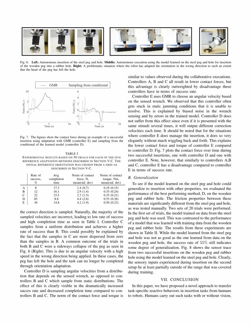
Fig. 6. Left: Autonomous insertion of the steel peg and hole. Middle: Autonomous execution using the model learned on the steel peg and hole for insertionof the wooden peg into a rubber hole. Right: A problematic situation where the robot has adapted the orientation in the wrong direction to such an extentthat the head of the peg has left the hole.
0 5 10−5
0
5
10
Time (s)
Forc
e (N
), x
0 5 10−4
−2
0
2
4
6
Time (s)
Forc
e (N
), y
GMR Sampling from conditional
Fig. 7. The figures show the contact force during an example of a successfulinsertion using adaptation with GMR (controller E) and sampling from theconditional of the learned model (controller D).
TABLE IEXPERIMENTAL RESULTS BASED ON 50 TRIALS FOR EACH OF THE FIVEREFERENCE ADAPTATION METHODS DESCRIBED IN SECTION V-C. THE
INITIAL REFERENCE ORIENTATION WAS CHOSEN FROM A GRID ASDESCRIBED IN SECTION V-C.
the correct direction is sampled. Naturally, the majority of thesampled velocities are incorrect, leading to low rate of successand high completion time as seen in Table I. Controller Csamples from a uniform distribution and achieves a higherrate of success than B. This could possibly be explained bythe fact that the samples in C are more dispersed from zerothan the samples in B. A common outcome of the trials inboth B and C were a sideways collapse of the peg as seen inFig. 6 (Right). This is due to an angular velocity with a highspeed in the wrong direction being applied. In these cases, thepeg has left the hole and the task can no longer be completedthrough orientation adaptation.
Controller D is sampling angular velocities from a distribu-tion that depends on the sensed wrench, as opposed to con-trollers B and C which sample from static distributions. Theeffect of this is clearly visible in the dramatically increasedsucces rate and decreased completion time compared to con-trollers B and C. The norm of the contact force and torque is
similar to values observed during the collaborative executions.Controllers A, B and C all result in lower contact forces, butthis advantage is clearly outweighted by disadvantage thesecontrollers have in terms of success rate.
Controller E uses GMR to choose an angular velocity basedon the sensed wrench. We observed that this controller oftengets stuck in static jamming conditions that it is unable toresolve. This is explained by biased noise in the wrenchsensing and by errors in the trained model. Controller D doesnot suffer from this effect since even if it is presented with thesame stimuli several times, it will output different correctionvelocities each time. It should be noted that for the situationswhere controller E does manage the insertion, it does so veryelegantly without much wiggling back and forth. This explainsthe lower contact force and torque of controller E comparedto controller D. Fig. 7 plots the contact force over time duringtwo successful insertions, one with controller D and one withcontroller E. Note, however, that similarly to controllers A,Band C, controller E has a disadvantage compared to controllerE in terms of success rate.
B. Generalization
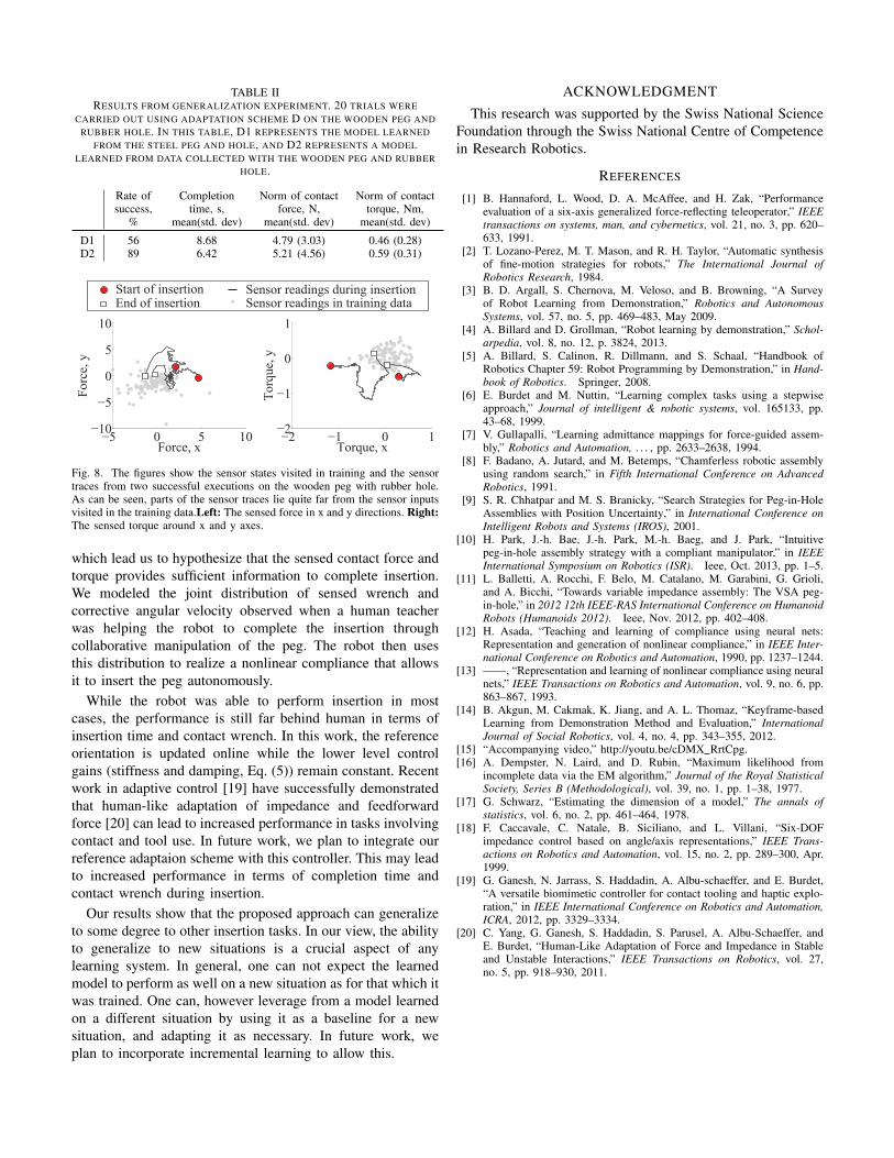
To see if the model learned on the steel peg and hole couldgeneralize to insertion with other properties, we evaluated theperformance of the best performing method, D, on the woodenpeg and rubber hole. The friction properties between thesematerials are significantly different from the steel peg and hole,as was tested manually. Two sets of 20 trials were performed.In the first set of trials, the model trained on data from the steelpeg and hole was used. This was contrasted to the performanceof a model that was learned with training data from the woodenpeg and rubber hole. The results from these experiments areshown in Table II. While the model learned from the steel pegand hole was not as good as the one learned from data on thewooden peg and hole, the success rate of 55% still indicatessome degree of generalization. Fig. 8 shows the sensor tracefrom two successful insertions on the wooden peg and rubberhole using the model learned on the steel peg and hole. Clearly,the sensory inputs experienced during insertion on the secondsetup lie at least partially outside of the range that was coveredduring training.
VII. CONCLUSION
In this paper, we have proposed a novel approach to transfertask-specific reactive behaviors in insertion tasks from humansto robots. Humans carry out such tasks with or without vision,
TABLE IIRESULTS FROM GENERALIZATION EXPERIMENT. 20 TRIALS WERE
CARRIED OUT USING ADAPTATION SCHEME D ON THE WOODEN PEG ANDRUBBER HOLE. IN THIS TABLE, D1 REPRESENTS THE MODEL LEARNED
FROM THE STEEL PEG AND HOLE, AND D2 REPRESENTS A MODELLEARNED FROM DATA COLLECTED WITH THE WOODEN PEG AND RUBBER
Sensor readings during insertionSensor readings in training data
Fig. 8. The figures show the sensor states visited in training and the sensortraces from two successful executions on the wooden peg with rubber hole.As can be seen, parts of the sensor traces lie quite far from the sensor inputsvisited in the training data.Left: The sensed force in x and y directions. Right:The sensed torque around x and y axes.
which lead us to hypothesize that the sensed contact force andtorque provides sufficient information to complete insertion.We modeled the joint distribution of sensed wrench andcorrective angular velocity observed when a human teacherwas helping the robot to complete the insertion throughcollaborative manipulation of the peg. The robot then usesthis distribution to realize a nonlinear compliance that allowsit to insert the peg autonomously.
While the robot was able to perform insertion in mostcases, the performance is still far behind human in terms ofinsertion time and contact wrench. In this work, the referenceorientation is updated online while the lower level controlgains (stiffness and damping, Eq. (5)) remain constant. Recentwork in adaptive control [19] have successfully demonstratedthat human-like adaptation of impedance and feedforwardforce [20] can lead to increased performance in tasks involvingcontact and tool use. In future work, we plan to integrate ourreference adaptaion scheme with this controller. This may leadto increased performance in terms of completion time andcontact wrench during insertion.
Our results show that the proposed approach can generalizeto some degree to other insertion tasks. In our view, the abilityto generalize to new situations is a crucial aspect of anylearning system. In general, one can not expect the learnedmodel to perform as well on a new situation as for that which itwas trained. One can, however leverage from a model learnedon a different situation by using it as a baseline for a newsituation, and adapting it as necessary. In future work, weplan to incorporate incremental learning to allow this.
ACKNOWLEDGMENT
This research was supported by the Swiss National ScienceFoundation through the Swiss National Centre of Competencein Research Robotics.
REFERENCES
[1] B. Hannaford, L. Wood, D. A. McAffee, and H. Zak, “Performanceevaluation of a six-axis generalized force-reflecting teleoperator,” IEEEtransactions on systems, man, and cybernetics, vol. 21, no. 3, pp. 620–633, 1991.
[2] T. Lozano-Perez, M. T. Mason, and R. H. Taylor, “Automatic synthesisof fine-motion strategies for robots,” The International Journal ofRobotics Research, 1984.
[3] B. D. Argall, S. Chernova, M. Veloso, and B. Browning, “A Surveyof Robot Learning from Demonstration,” Robotics and AutonomousSystems, vol. 57, no. 5, pp. 469–483, May 2009.
[4] A. Billard and D. Grollman, “Robot learning by demonstration,” Schol-arpedia, vol. 8, no. 12, p. 3824, 2013.
[5] A. Billard, S. Calinon, R. Dillmann, and S. Schaal, “Handbook ofRobotics Chapter 59: Robot Programming by Demonstration,” in Hand-book of Robotics. Springer, 2008.
[6] E. Burdet and M. Nuttin, “Learning complex tasks using a stepwiseapproach,” Journal of intelligent & robotic systems, vol. 165133, pp.43–68, 1999.
[7] V. Gullapalli, “Learning admittance mappings for force-guided assem-bly,” Robotics and Automation, . . . , pp. 2633–2638, 1994.
[8] F. Badano, A. Jutard, and M. Betemps, “Chamferless robotic assemblyusing random search,” in Fifth International Conference on AdvancedRobotics, 1991.
[9] S. R. Chhatpar and M. S. Branicky, “Search Strategies for Peg-in-HoleAssemblies with Position Uncertainty,” in International Conference onIntelligent Robots and Systems (IROS), 2001.
[10] H. Park, J.-h. Bae, J.-h. Park, M.-h. Baeg, and J. Park, “Intuitivepeg-in-hole assembly strategy with a compliant manipulator,” in IEEEInternational Symposium on Robotics (ISR). Ieee, Oct. 2013, pp. 1–5.
[11] L. Balletti, A. Rocchi, F. Belo, M. Catalano, M. Garabini, G. Grioli,and A. Bicchi, “Towards variable impedance assembly: The VSA peg-in-hole,” in 2012 12th IEEE-RAS International Conference on HumanoidRobots (Humanoids 2012). Ieee, Nov. 2012, pp. 402–408.
[12] H. Asada, “Teaching and learning of compliance using neural nets:Representation and generation of nonlinear compliance,” in IEEE Inter-national Conference on Robotics and Automation, 1990, pp. 1237–1244.
[13] ——, “Representation and learning of nonlinear compliance using neuralnets,” IEEE Transactions on Robotics and Automation, vol. 9, no. 6, pp.863–867, 1993.
[14] B. Akgun, M. Cakmak, K. Jiang, and A. L. Thomaz, “Keyframe-basedLearning from Demonstration Method and Evaluation,” InternationalJournal of Social Robotics, vol. 4, no. 4, pp. 343–355, 2012.
[15] “Accompanying video,” http://youtu.be/cDMX RrtCpg.[16] A. Dempster, N. Laird, and D. Rubin, “Maximum likelihood from
incomplete data via the EM algorithm,” Journal of the Royal StatisticalSociety, Series B (Methodological), vol. 39, no. 1, pp. 1–38, 1977.
[17] G. Schwarz, “Estimating the dimension of a model,” The annals ofstatistics, vol. 6, no. 2, pp. 461–464, 1978.
[18] F. Caccavale, C. Natale, B. Siciliano, and L. Villani, “Six-DOFimpedance control based on angle/axis representations,” IEEE Trans-actions on Robotics and Automation, vol. 15, no. 2, pp. 289–300, Apr.1999.
[19] G. Ganesh, N. Jarrass, S. Haddadin, A. Albu-schaeffer, and E. Burdet,“A versatile biomimetic controller for contact tooling and haptic explo-ration,” in IEEE International Conference on Robotics and Automation,ICRA, 2012, pp. 3329–3334.
[20] C. Yang, G. Ganesh, S. Haddadin, S. Parusel, A. Albu-Schaeffer, andE. Burdet, “Human-Like Adaptation of Force and Impedance in Stableand Unstable Interactions,” IEEE Transactions on Robotics, vol. 27,no. 5, pp. 918–930, 2011.