24
© Copyright 2005-7 Pico Technology Limited. All rights reserved. TC-08 User's Guide tc08.en-3 Thermocouple Logger

© Copyright 2005-7 Pico Technology Limited. All rights reserved.
TC-08
User's Guide
tc08.en-3
Thermocouple Logger

TC-08 User's GuideI
© Copyright 2005-7 Pico Technology Limited. All rights reserved.tc08.en
Contents.....................................................................................................................................11 Introduction
...........................................................................................................................................11 Overview
...........................................................................................................................................12 Installing the driver
...........................................................................................................................................13 Connecting the TC-08
...........................................................................................................................................44 Legal information
...........................................................................................................................................55 Safety warning
.....................................................................................................................................62 Product information
...........................................................................................................................................61 Specifications
...........................................................................................................................................72 Principles of operation
.....................................................................................................................................83 Technical reference
...........................................................................................................................................81 Introduction
...........................................................................................................................................82 Serial port settings
...........................................................................................................................................83 Connections
...........................................................................................................................................94 Protocol
...........................................................................................................................................115 Modem operation
...........................................................................................................................................116 Operating systems
...........................................................................................................................................111 Windows XP and Vista
...........................................................................................................................................127 Driver routines
...........................................................................................................................................121 Introduction
...........................................................................................................................................132 tc08_open_unit
...........................................................................................................................................133 tc08_get_cycle
...........................................................................................................................................134 tc08_close_unit
...........................................................................................................................................135 tc08_poll_driver
...........................................................................................................................................146 tc08_set_channel
...........................................................................................................................................157 tc08_set_resolution
...........................................................................................................................................158 tc08_get_version
...........................................................................................................................................159 tc08_get_temp
...........................................................................................................................................1610 tc08_get_cold_junction
.....................................................................................................................................174 Programming support
...........................................................................................................................................171 C/C++ Windows
...........................................................................................................................................182 Delphi
...........................................................................................................................................183 Excel
...........................................................................................................................................184 LabVIEW
...........................................................................................................................................185 Visual Basic
...........................................................................................................................................196 Agilent VEE
...........................................................................................................................................197 Linux
..............................................................................................................................................20Index

Introduction 1
© Copyright 2005-7 Pico Technology Limited. All rights reserved. tc08.en
1 Introduction1.1 Overview
The Pico TC-08 is a complete thermocouple input device for use with IBM-compatiblecomputers. It can be used with the supplied PicoLog data logging program. Alternatively, you can use the TC-08 driver software to develop your own programs to collect and analyse data from the unit.
The TC-08 software provides all of the calculations necessary for cold junctioncompensation and for thermocouple curve normalisation. The TC-08 is a highlyaccurate without calibration, and the software does contain facilities to make minoradjustments to the gain and offset.
PicoLog and the drivers support up to nine TC-08 units.
This manual describes the physical and electrical properties of the TC-08, andexplains how to use the software drivers. For information on PicoLog software, pleaseconsult the PicoLog help file.
1.2 Installing the driver
Installation of the driver is done automatically when you install the PicoLog software.Alternately, you can download the driver from our website at http://www.picotech.com.
1.3 Connecting the TC-08
To begin using the TC-08, you should connect the D-connector on the TC-08 to theserial port on your computer using the cable provided. If you have a 25-way serialport, use a 9 to 25 way adaptor. Next, connect a thermocouple to one or more of thethermocouple input connectors. Now, to set up the unit with your chosenthermocouple, do the following:
1. Open PicoLog Recorder
2. From the File menu, select New settings. The Recording dialog box appears:
TC-08 User's Guide2
© Copyright 2005-7 Pico Technology Limited. All rights reserved.tc08.en
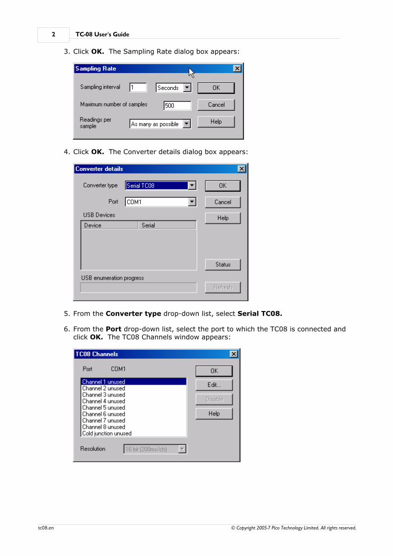
3. Click OK. The Sampling Rate dialog box appears:
4. Click OK. The Converter details dialog box appears:
5. From the Converter type drop-down list, select Serial TC08.
6. From the Port drop-down list, select the port to which the TC08 is connected andclick OK. The TC08 Channels window appears:

Introduction 3
© Copyright 2005-7 Pico Technology Limited. All rights reserved. tc08.en
7. In the TC08 Channels window, double-click on Channel 1 unused. The Edit TC08Channel dialog box appears:
8. From the Thermocouple drop-down list, select the thermocouple type you wish touse, then click OK. The recorder view should now display the temperature.

TC-08 User's Guide4
© Copyright 2005-7 Pico Technology Limited. All rights reserved.tc08.en
1.4 Legal information
The material contained in this release is licensed, not sold. Pico Technology Limitedgrants a license to the person who installs this software, subject to the conditionslisted below.
Access
The licensee agrees to allow access to this software only to persons who have beeninformed of these conditions and agree to abide by them.
Usage
The software in this release is for use only with Pico products or with data collectedusing Pico products.
Copyright
Pico Technology Limited claims the copyright of, and retains the rights to, all material(software, documents etc.) contained in this release. You may copy and distribute theentire release in its original state, but must not copy individual items within therelease other than for backup purposes.
Liability
Pico Technology and its agents shall not be liable for any loss, damage or injury,howsoever caused, related to the use of Pico Technology equipment or software,unless excluded by statute.
Fitness for purpose
No two applications are the same: Pico Technology cannot guarantee that itsequipment or software is suitable for a given application. It is your responsibility,therefore, to ensure that the product is suitable for your application.
Mission-critical applications
This software is intended for use on a computer that may be running other softwareproducts. For this reason, one of the conditions of the license is that it excludes usagein mission-critical applications, for example life-support systems.
Viruses
This software was continuously monitored for viruses during production, but you areresponsible for virus-checking the software once it is installed.
Support
If you are unsatisfied with the performance of this software, please contact ourtechnical support staff, who will try to fix the problem within a reasonable time scale.If you are still dissatisfied, please return the product and software to your supplierwithin 28 days of purchase for a full refund.
Upgrades
We provide upgrades, free of charge, from our web site at www.picotech.com. Wereserve the right to charge for updates or replacements sent out on physical media.
Trademarks
Pico Technology Limited, PicoScope, PicoLog, DrDAQ and EnviroMon are trademarks ofPico Technology Limited, registered in the United Kingdom and other countries
Pico Technology acknowledges the following product names as trademarks of theirrespective owners: Windows, Excel, Visual Basic, LabVIEW, Agilent VEE, HPVEE, Delphi.
Introduction 5
© Copyright 2005-7 Pico Technology Limited. All rights reserved. tc08.en
1.5 Safety warning
We strongly recommend that you read the general safety information below beforeusing your product for the first time. If the equipment is not used in the mannerspecified, then the protection provided may be impaired. This could result in damageto your computer and/or injury to yourself or others.
Maximum input range
The TC-08 is designed to measure voltages in the range of ±60mV. Any voltages inexcess of ±10V may cause permanent damage to the unit.
Mains voltages
Pico products are not designed for use with mains voltages. To measure mains werecommend the use of a differential isolating probe specifically designed for suchmeasurements.
Safety grounding
The ground of every product is connected directly to the ground of your computer viathe interconnecting cable provided. This is done in order to minimise interference. Ifthe PC (especially laptop) is not grounded, reading stability cannot be guaranteed andit may be necessary to manually ground the equipment.
As with most oscilloscopes and data loggers, you should take care to avoid connectingthe inputs of the product to anything which may be at a hazardous voltage. If indoubt, use a meter to check that there is no hazardous AC or DC voltage. Failure tocheck may cause damage to the product and/or computer and could cause injury toyourself or others.
Take great care when measuring temperatures near mains equipment. If a sensor isaccidentally connected to mains voltages, you risk damage to the converter or yourcomputer and your computer chassis may become live.
You should assume that the product does not have a protective safety earth. Incorrectconfiguration or use of the device to measure voltages outside the maximum inputrange can be hazardous.
Repairs
The unit contains no user-serviceable parts: repair or calibration of the unit requiresspecialised test equipment and must be performed by Pico Technology Limited or theirauthorised distributors.
TC-08 User's Guide6
© Copyright 2005-7 Pico Technology Limited. All rights reserved.tc08.en
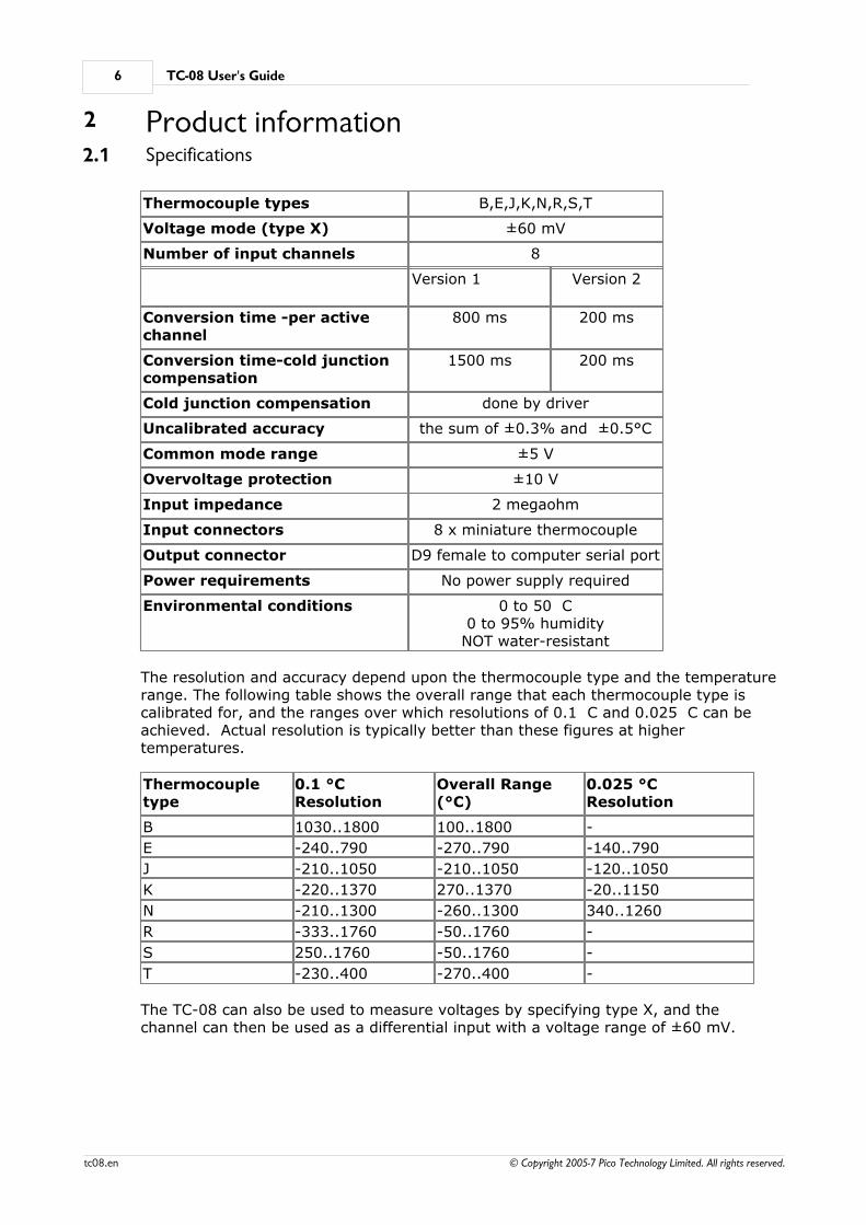
2 Product information2.1 Specifications
Thermocouple types B,E,J,K,N,R,S,T
Voltage mode (type X) ±60 mV
Number of input channels 8
Version 1
Version 2
Conversion time -per activechannel
800 ms 200 ms
Conversion time-cold junctioncompensation
1500 ms 200 ms
Cold junction compensation done by driver
Uncalibrated accuracy the sum of ±0.3% and ±0.5°C
Common mode range ±5 V
Overvoltage protection ±10 V
Input impedance 2 megaohm
Input connectors 8 x miniature thermocouple
Output connector D9 female to computer serial port
Power requirements No power supply required
Environmental conditions 0 to 50 C0 to 95% humidity
NOT water-resistant
The resolution and accuracy depend upon the thermocouple type and the temperaturerange. The following table shows the overall range that each thermocouple type iscalibrated for, and the ranges over which resolutions of 0.1 C and 0.025 C can beachieved. Actual resolution is typically better than these figures at highertemperatures.
Thermocoupletype
0.1 °CResolution
Overall Range(°C)
0.025 °CResolution
B 1030..1800 100..1800 -
E -240..790 -270..790 -140..790
J -210..1050 -210..1050 -120..1050
K -220..1370 270..1370 -20..1150
N -210..1300 -260..1300 340..1260
R -333..1760 -50..1760 -
S 250..1760 -50..1760 -
T -230..400 -270..400 -
The TC-08 can also be used to measure voltages by specifying type X, and thechannel can then be used as a differential input with a voltage range of ±60 mV.
Product information 7
© Copyright 2005-7 Pico Technology Limited. All rights reserved. tc08.en
2.2 Principles of operation
An electric current flows in a closed circuit of two dissimilar metals when the twojunctions are held at different temperatures.
In such a circuit, called a thermocouple, the magnitude and direction of the currentare functions of the temperature difference between the junctions and of the thermalproperties of the metals used in the circuit. This phenomenon is known as theSeebeck Effect.
The conductors can be made of any two dissimilar metals, and when the hot junctionis heated the current flow can be observed. If the positions of the hot and coldjunctions are reversed, current will flow in the opposite direction.
In fact, a thermocouple circuit will actually generate a measurable, low-voltage outputthat is almost directly proportional to the temperature difference between the hotjunction and the cold junction. A unit change in this temperature difference producessome net change in the voltage.
Note: More information on choosing and using thermocouples can be found here.
TC-08 User's Guide8
© Copyright 2005-7 Pico Technology Limited. All rights reserved.tc08.en
3 Technical reference3.1 Introduction
Serial port settingsConnectionsProtocolModem operation
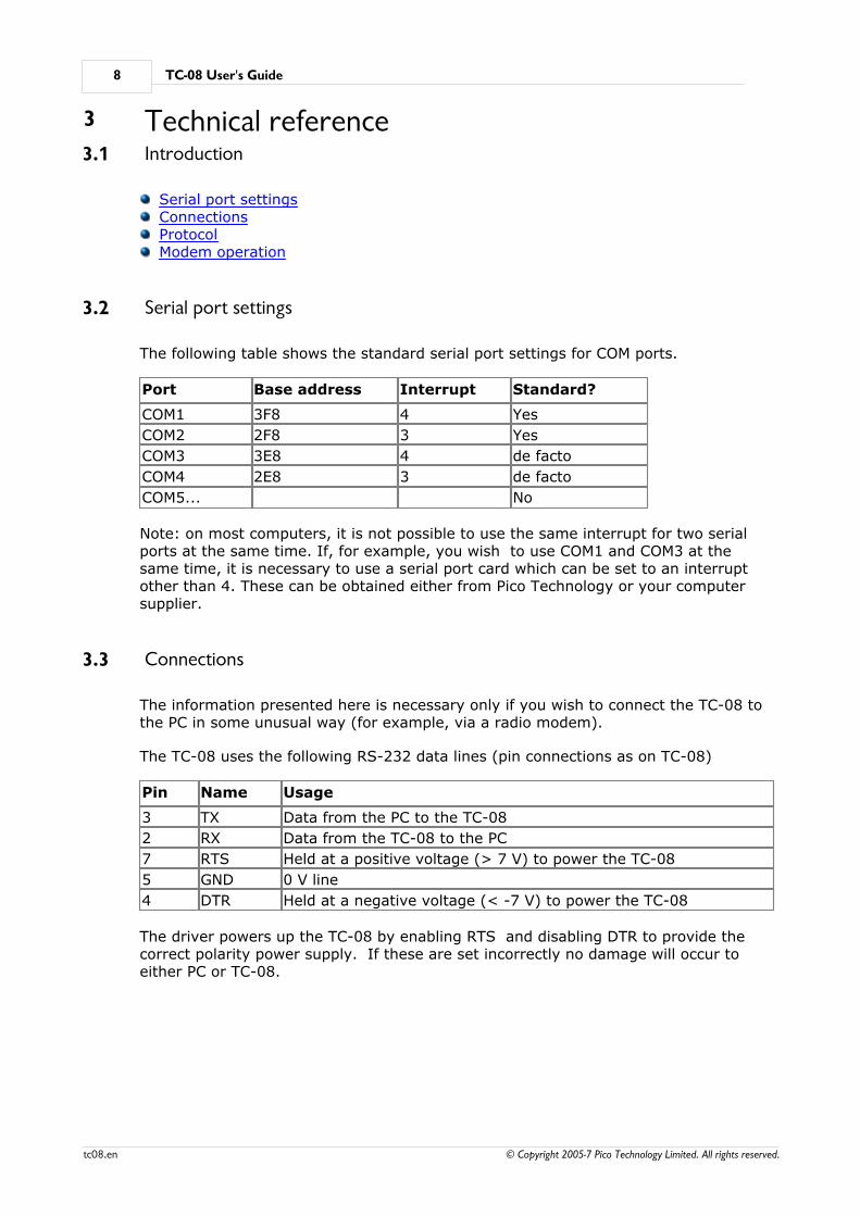
3.2 Serial port settings
The following table shows the standard serial port settings for COM ports.
Port Base address Interrupt Standard?
COM1 3F8 4 Yes
COM2 2F8 3 Yes
COM3 3E8 4 de facto
COM4 2E8 3 de facto
COM5... No
Note: on most computers, it is not possible to use the same interrupt for two serialports at the same time. If, for example, you wish to use COM1 and COM3 at thesame time, it is necessary to use a serial port card which can be set to an interruptother than 4. These can be obtained either from Pico Technology or your computersupplier.
3.3 Connections
The information presented here is necessary only if you wish to connect the TC-08 tothe PC in some unusual way (for example, via a radio modem).
The TC-08 uses the following RS-232 data lines (pin connections as on TC-08)
Pin Name Usage
3 TX Data from the PC to the TC-08
2 RX Data from the TC-08 to the PC
7 RTS Held at a positive voltage (> 7 V) to power the TC-08
5 GND 0 V line
4 DTR Held at a negative voltage (< -7 V) to power the TC-08
The driver powers up the TC-08 by enabling RTS and disabling DTR to provide thecorrect polarity power supply. If these are set incorrectly no damage will occur toeither PC or TC-08.

Technical reference 9
© Copyright 2005-7 Pico Technology Limited. All rights reserved. tc08.en
3.4 Protocol
About a second after powering on the TC-08, the driver can communicate with theTC-08 as a normal RS-232 device. The TC-08 operates at 9600 baud with 1 stop bitand no parity.
The driver controls the TC-08 using the following sequence:
1. Switch RTS on and DTR off to provide power.2. Wait for more than 1 second for the TC-08 to settle3. Send an single control byte to the TC-084. Wait for the 3-byte response from the TC-08
Steps 3 and 4 are repeated for each measurement.
The TC-08 signals the end of conversion by sending three bytes. No data should besent to the TC-08 during the conversion, as it may be lost or corrupted.
The following control codes are used:
0x00, /* Channel 1 */ 0x20, /* Channel 2 */ 0x40, /* Channel 3 */ 0x60, /* Channel 4 */ 0x80, /* Channel 5 */ 0xA0, /* Channel 6 */ 0xC0, /* Channel 7 */ 0xE0, /* Channel 8 */ 0x01, /* version */ 0x22, /* Cold junction- reference */ 0x42 /* Cold junction- thermistor */
For the channels, the returned value is a three-byte sequence.
Byte 1 is the sign '+' or '-'
Byte 2 is the most significant byte of the reading
Byte 3 is the least significant byte of the reading.
The reading is a 16-bit plus sign number, where 0 microvolts is represented by areading of zero, and +/- 59,524 microvolts are represented by +/- 65,535.
The cold junction temperature is calculated using the readings from the reference(ref) and the thermistor (th),
divisor = (th + 65535L) / 65536L
Result = (65536L * (th / divisor)) / (ref / divisor)
The result is converted to temperature using the following table:
/* 0000 */ 230216L, /* 0001 */ 218272L, /* 0002 */ 206947L, /* 0003 */ 196210L, /* 0004 */ 186030L, /* 0005 */ 176378L, /* 0006 */ 167491L, /* 0007 */ 159051L, /* 0008 */ 151037L,
TC-08 User's Guide10
© Copyright 2005-7 Pico Technology Limited. All rights reserved.tc08.en
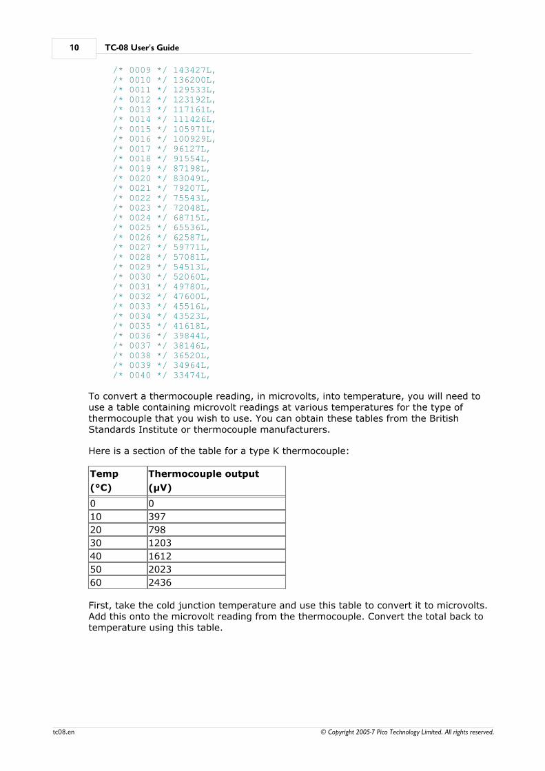
/* 0009 */ 143427L, /* 0010 */ 136200L, /* 0011 */ 129533L, /* 0012 */ 123192L, /* 0013 */ 117161L, /* 0014 */ 111426L, /* 0015 */ 105971L, /* 0016 */ 100929L, /* 0017 */ 96127L, /* 0018 */ 91554L, /* 0019 */ 87198L, /* 0020 */ 83049L, /* 0021 */ 79207L, /* 0022 */ 75543L, /* 0023 */ 72048L, /* 0024 */ 68715L, /* 0025 */ 65536L, /* 0026 */ 62587L, /* 0027 */ 59771L, /* 0028 */ 57081L, /* 0029 */ 54513L, /* 0030 */ 52060L, /* 0031 */ 49780L, /* 0032 */ 47600L, /* 0033 */ 45516L, /* 0034 */ 43523L, /* 0035 */ 41618L, /* 0036 */ 39844L, /* 0037 */ 38146L, /* 0038 */ 36520L, /* 0039 */ 34964L, /* 0040 */ 33474L,
To convert a thermocouple reading, in microvolts, into temperature, you will need touse a table containing microvolt readings at various temperatures for the type ofthermocouple that you wish to use. You can obtain these tables from the BritishStandards Institute or thermocouple manufacturers.
Here is a section of the table for a type K thermocouple:
Temp
(°C)
Thermocouple output
(µV)
0 0
10 397
20 798
30 1203
40 1612
50 2023
60 2436
First, take the cold junction temperature and use this table to convert it to microvolts.Add this onto the microvolt reading from the thermocouple. Convert the total back totemperature using this table.
Technical reference 11
© Copyright 2005-7 Pico Technology Limited. All rights reserved. tc08.en
3.5 Modem operation
The TC-08 is normally connected directly to the computer, but it is also possible toaccess the TC-08 via a modem using the Windows driver.
It is necessary to provide power to the TC-08, either by instructing the modem toprovide power or by connecting a power supply directly to the TC-08. See serialconnections for information.
For some radio modems, there is a delay between sending text to the modem and itsarrival at the other end, and a similar delay for the response from the TC08. If, forexample, the maximum possible delay is 150 ms each way, 300 ms total, thefollowing text should be added to win.ini so that the driver waits longer for each
response.
[TC08]Turnround=300
Warning: In order to comply with current legislation, use only radio modems whichcomply with the RTTE directive.
3.6 Operating systems
3.6.1 Windows XP and Vista
Most applications running under Windows XP and Vista are 32-bit applications. The32-bit Windows driver is the file TC0832.dll, installed in the drivers directory. If an
application is unable to find the DLL, try moving the DLL to windows/system.
TC-08 User's Guide12
© Copyright 2005-7 Pico Technology Limited. All rights reserved.tc08.en
3.7 Driver routines
3.7.1 Introduction
The TC-08 is supplied with driver routines that you can build into your own programs. Drivers are supplied for the following operating systems:
Windows XP/Vista
Once you have installed the software, the DRIVERS directory contains the drivers and
a selection of examples of how to use the drivers. It also contains a copy of thismanual as a text file. If you installed under Windows, the Pico Technology groupcontains a help file for the drivers. See the Readme.doc file in the DRIVERS directory
for the filenames.
The driver routine is supplied as a Dynamic Link Library for Windows.
The object files use Pascal linkage conventions and do not require any compilerrun-time routines. They can therefore be used with most real-mode and someprotected-mode C compilers.
The Windows DLL can be used with C, Delphi and Visual Basic programs: it can alsobe used with programs like Microsoft Excel, where the macro language is a form ofVisual Basic. More than one application can access the Windows DLL at the sametime, as long as the applications do not change the settings for channels that they arenot using.
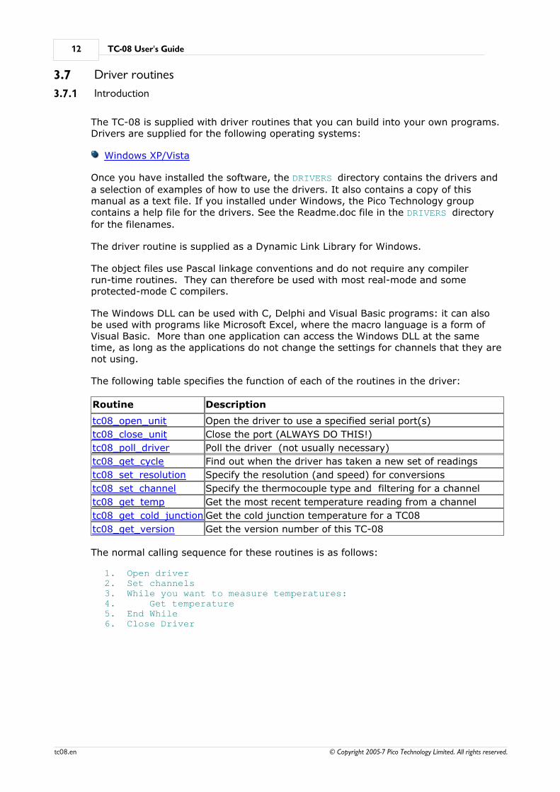
The following table specifies the function of each of the routines in the driver:
Routine Description
tc08_open_unit Open the driver to use a specified serial port(s)
tc08_close_unit Close the port (ALWAYS DO THIS!)
tc08_poll_driver Poll the driver (not usually necessary)
tc08_get_cycle Find out when the driver has taken a new set of readings
tc08_set_resolution Specify the resolution (and speed) for conversions
tc08_set_channel Specify the thermocouple type and filtering for a channel
tc08_get_temp Get the most recent temperature reading from a channel
tc08_get_cold_junction Get the cold junction temperature for a TC08
tc08_get_version Get the version number of this TC-08
The normal calling sequence for these routines is as follows:
1. Open driver2. Set channels3. While you want to measure temperatures:4. Get temperature5. End While6. Close Driver
Technical reference 13
© Copyright 2005-7 Pico Technology Limited. All rights reserved. tc08.en
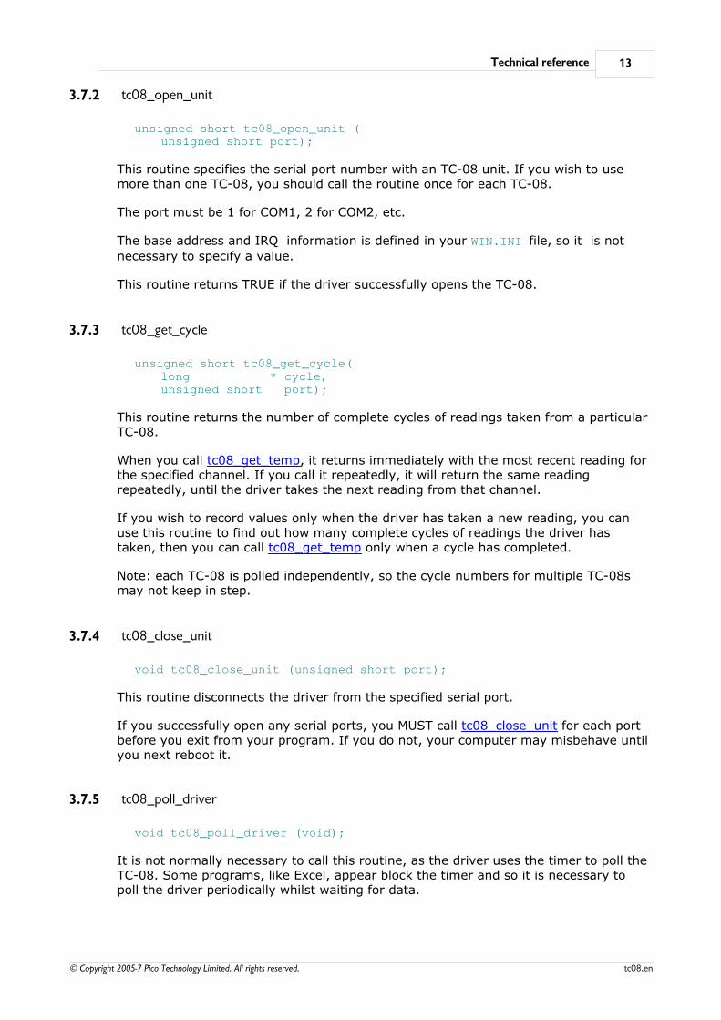
3.7.2 tc08_open_unit
unsigned short tc08_open_unit (unsigned short port);
This routine specifies the serial port number with an TC-08 unit. If you wish to usemore than one TC-08, you should call the routine once for each TC-08.
The port must be 1 for COM1, 2 for COM2, etc.
The base address and IRQ information is defined in your WIN.INI file, so it is not
necessary to specify a value.
This routine returns TRUE if the driver successfully opens the TC-08.
3.7.3 tc08_get_cycle
unsigned short tc08_get_cycle(long * cycle, unsigned short port);
This routine returns the number of complete cycles of readings taken from a particularTC-08.
When you call tc08_get_temp, it returns immediately with the most recent reading forthe specified channel. If you call it repeatedly, it will return the same readingrepeatedly, until the driver takes the next reading from that channel.
If you wish to record values only when the driver has taken a new reading, you canuse this routine to find out how many complete cycles of readings the driver hastaken, then you can call tc08_get_temp only when a cycle has completed.
Note: each TC-08 is polled independently, so the cycle numbers for multiple TC-08smay not keep in step.
3.7.4 tc08_close_unit
void tc08_close_unit (unsigned short port);
This routine disconnects the driver from the specified serial port.
If you successfully open any serial ports, you MUST call tc08_close_unit for each portbefore you exit from your program. If you do not, your computer may misbehave untilyou next reboot it.
3.7.5 tc08_poll_driver
void tc08_poll_driver (void);
It is not normally necessary to call this routine, as the driver uses the timer to poll theTC-08. Some programs, like Excel, appear block the timer and so it is necessary topoll the driver periodically whilst waiting for data.
TC-08 User's Guide14
© Copyright 2005-7 Pico Technology Limited. All rights reserved.tc08.en
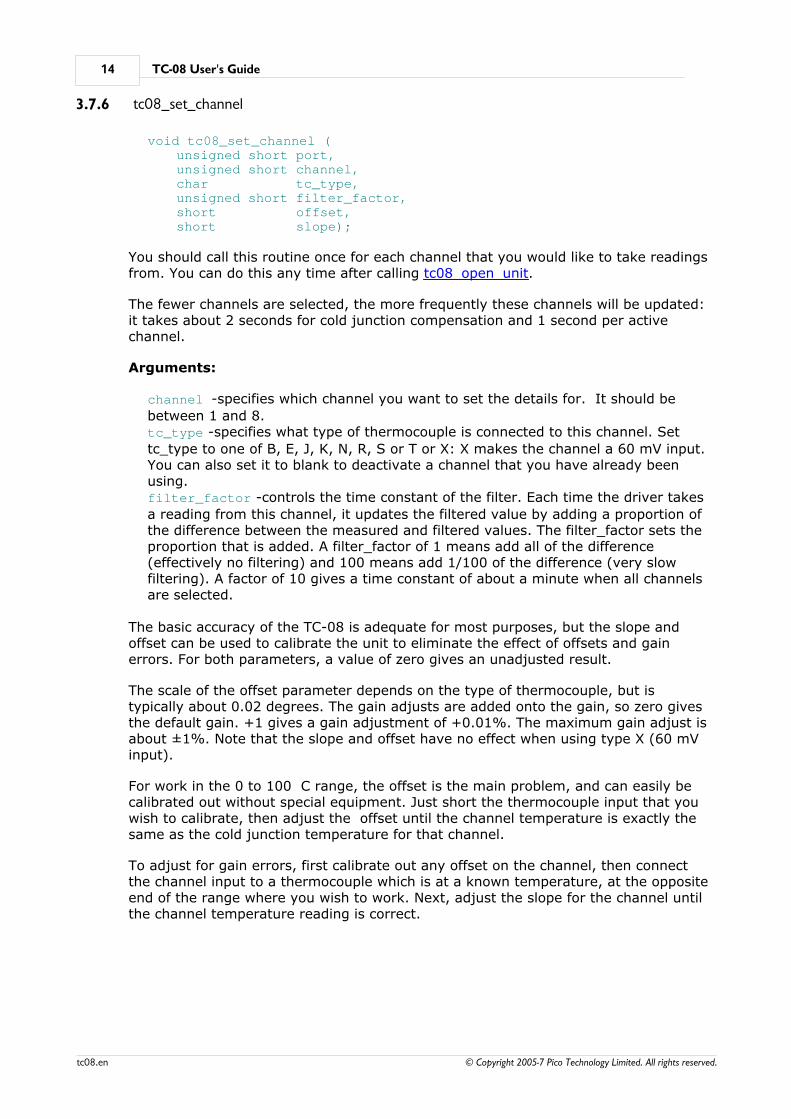
3.7.6 tc08_set_channel
void tc08_set_channel (unsigned short port,unsigned short channel,char tc_type,unsigned short filter_factor,short offset,short slope);
You should call this routine once for each channel that you would like to take readingsfrom. You can do this any time after calling tc08_open_unit.
The fewer channels are selected, the more frequently these channels will be updated:it takes about 2 seconds for cold junction compensation and 1 second per activechannel.
Arguments:
channel -specifies which channel you want to set the details for. It should be
between 1 and 8.tc_type -specifies what type of thermocouple is connected to this channel. Set
tc_type to one of B, E, J, K, N, R, S or T or X: X makes the channel a 60 mV input.You can also set it to blank to deactivate a channel that you have already beenusing.filter_factor -controls the time constant of the filter. Each time the driver takes
a reading from this channel, it updates the filtered value by adding a proportion ofthe difference between the measured and filtered values. The filter_factor sets theproportion that is added. A filter_factor of 1 means add all of the difference(effectively no filtering) and 100 means add 1/100 of the difference (very slowfiltering). A factor of 10 gives a time constant of about a minute when all channelsare selected.
The basic accuracy of the TC-08 is adequate for most purposes, but the slope andoffset can be used to calibrate the unit to eliminate the effect of offsets and gainerrors. For both parameters, a value of zero gives an unadjusted result.
The scale of the offset parameter depends on the type of thermocouple, but istypically about 0.02 degrees. The gain adjusts are added onto the gain, so zero givesthe default gain. +1 gives a gain adjustment of +0.01%. The maximum gain adjust isabout ±1%. Note that the slope and offset have no effect when using type X (60 mVinput).
For work in the 0 to 100 C range, the offset is the main problem, and can easily becalibrated out without special equipment. Just short the thermocouple input that youwish to calibrate, then adjust the offset until the channel temperature is exactly thesame as the cold junction temperature for that channel.
To adjust for gain errors, first calibrate out any offset on the channel, then connectthe channel input to a thermocouple which is at a known temperature, at the oppositeend of the range where you wish to work. Next, adjust the slope for the channel untilthe channel temperature reading is correct.
Technical reference 15
© Copyright 2005-7 Pico Technology Limited. All rights reserved. tc08.en
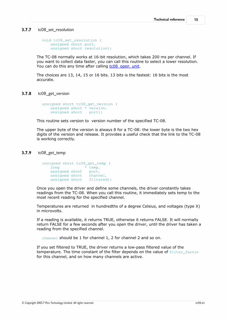
3.7.7 tc08_set_resolution
void tc08_set_resolution (unsigned short port,unsigned short resolution);
The TC-08 normally works at 16-bit resolution, which takes 200 ms per channel. Ifyou want to collect data faster, you can call this routine to select a lower resolution.You can do this any time after calling tc08_open_unit.
The choices are 13, 14, 15 or 16 bits. 13 bits is the fastest: 16 bits is the mostaccurate.
3.7.8 tc08_get_version
unsigned short tc08_get_version (unsigned short * version,unsigned short port);
This routine sets version to version number of the specified TC-08.
The upper byte of the version is always 8 for a TC-08: the lower byte is the two hexdigits of the version and release. It provides a useful check that the link to the TC-08is working correctly.
3.7.9 tc08_get_temp
unsigned short tc08_get_temp (long * temp, unsigned short port,unsigned short channel, unsigned short filtered);
Once you open the driver and define some channels, the driver constantly takesreadings from the TC-08. When you call this routine, it immediately sets temp to themost recent reading for the specified channel.
Temperatures are returned in hundredths of a degree Celsius, and voltages (type X)in microvolts.
If a reading is available, it returns TRUE, otherwise it returns FALSE. It will normallyreturn FALSE for a few seconds after you open the driver, until the driver has taken areading from the specified channel.
channel should be 1 for channel 1, 2 for channel 2 and so on.
If you set filtered to TRUE, the driver returns a low-pass filtered value of thetemperature. The time constant of the filter depends on the value of filter_factor
for this channel, and on how many channels are active.
TC-08 User's Guide16
© Copyright 2005-7 Pico Technology Limited. All rights reserved.tc08.en
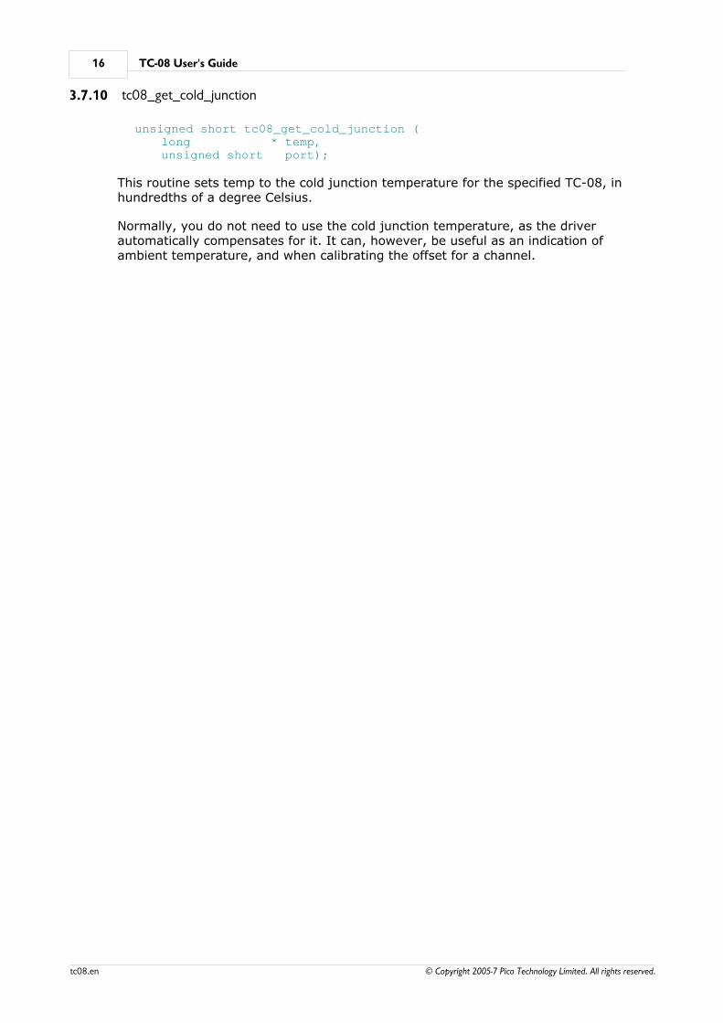
3.7.10 tc08_get_cold_junction
unsigned short tc08_get_cold_junction (long * temp,unsigned short port);
This routine sets temp to the cold junction temperature for the specified TC-08, inhundredths of a degree Celsius.
Normally, you do not need to use the cold junction temperature, as the driverautomatically compensates for it. It can, however, be useful as an indication ofambient temperature, and when calibrating the offset for a channel.
Programming support 17
© Copyright 2005-7 Pico Technology Limited. All rights reserved. tc08.en
4 Programming support4.1 C/C++ Windows
The C example source code is generic for windows applications - (ie - it does notcontain a files specific to a compiler or IDE). However there are two library filessupplied which are compiler dependant: tc0832.lib (for Borland and other OMF
compatible compilers) and tc08ms.lib (for Microsoft Visual C++ and other COFF
compatible compilers).
C++ (Windows)
C++ programs can access all versions of the driver. If tc08.h is included in a C++
program, the PREF1 macro expands to extern "C". This disables name decoration,
and enables C++ routines to make calls to the driver routines using C headers.
Windows GUI Application
To compile the programs, create a new project for an Application containing thefollowing files:
tc08tes.ctc08tes.rc
and either
tc0832.lib - Borland (OMF) 32-bit applications
ortc08ms.lib - Microsoft Visual C++ (COFF) 32-bit applications
The following files must be in the same directory:
tc08tes.rchtc08.h
tc0832.dll (All 32-bit applications)
Windows Console Application
To compile the programs, create a new project for an Application containing thefollowing files:
tc08con.c
and either
tc0832.lib - Borland (OMF) 32-bit applications
ortc08ms.lib - Microsoft Visual C++ (COFF) 32-bit applications
The following files must be in the same directory:
tc08.h
tc0832.dll (All 32-bit applications)

TC-08 User's Guide18
© Copyright 2005-7 Pico Technology Limited. All rights reserved.tc08.en
4.2 Delphi
The WIN subdirectory contains a simple program tc08.dpr which opens the drivers
and reads temperatures from the three channels. You will need the following files tobuild a complete program.
tc08fm.dfm
tc08fm.pas
tc08.inc
The file tc08.inc contains procedure prototypes for the driver routines: you can
include this file in your application. This example has been tested with Delphi versions1, 2 and 3.
4.3 Excel
The easiest way to get data into Excel is to use PicoLog.
If, however, you need to do something that is not possible using PicoLog, you canwrite an Excel macro which calls tc08xx.dll to read in a set of data values. The Excel
Macro language is similar to Visual Basic.
Excel 7
The example TC0832.XLS reads in 20 values of the cold junction temperature and
channel 1 temperature, one per second, and assigns them to cells A1..B20.
4.4 LabVIEW
The routines described here were tested using LabVIEW for Windows 95 version 4.0.
While it is possible to access all of the driver routines described earlier, it is easier touse the special LabVIEW access routine. The tc08.llb library in the DRIVERS
subdirectory shows how to access this routine.
To use this routine, copy tc08.llb and tc0832.dll to your LabVIEW user.lib
directory.
You will then the tc08 sub-vi, and an example sub-vi which demonstrate how to use
them. You can use one of these sub-vis for each of the channels that you wish tomeasure. The sub-vi accepts the port (1 for COM1), the channel (1 to 3) thethermocouple type ('K' for type K). The sub-vi returns a temperature forthermocouple types, and a voltage in microvolts for type X.
4.5 Visual Basic
Version 4 and 5
The DRIVERS subdirectory contains the following files:
TC0832.VBPTC0832.BASTC0832.FRM

Programming support 19
© Copyright 2005-7 Pico Technology Limited. All rights reserved. tc08.en
4.6 Agilent VEE
The example program tc08.vee shows how to collect a block of data from the TC-08.
You will need to copy the following files to the program directory:
tc08.vh
4.7 Linux
See the tc08.tar file for more information.

TC-08 User's Guide20
© Copyright 2005-7 Pico Technology Limited. All rights reserved.tc08.en
Index
CCold junction 7
Connecting the TC-08 1
Connections 8
DData lines 8
Delphi 18
EExcel 18
HHP-Vee 19
IInstallation 1
LLabview 18
Legal information 4
LINUX 19
MModem operation 11
PProtocol 9
SSafety warning 5
Seebeck Effect 7
Serial port settings 8
Specifications 6
Ttc08_close_unit 13
tc08_get_cold_junction 16
tc08_get_cycle 13
tc08_get_temp 15
tc08_get_version 15
tc08_open_unit 13
tc08_poll_driver 13
tc08_set_channel 14
tc08_set_resolution 15
Temperature table 9
Thermocouple circuits 7
VVisual Basic 18
WWindows NT 11

21
© Copyright 2005-7 Pico Technology Limited. All rights reserved. tc08.en

Pico Technology Ltd
The Mill HouseCambridge Street
St Neots PE19 1QBUnited Kingdom
Tel: +44 (0) 1480 396 395Fax: +44 (0) 1480 396 296Web: www.picotech.com
© Copyright 2005-7 Pico Technology Limited. All rights reserved.tc08.en 1.10.07


