32
TC-200 TRANSFER CASE SERVICE MANUAL Part Number 873-0042-001 FABCO AUTOMOTIVE CORPORATION, Livermore, CA AUTOMOTIVE CORPORATION

TC-200 TRANSFER CASESERVICE MANUAL
Part Number873-0042-001
FABCO AUTOMOTIVE CORPORATION, Livermore, CA 5/99
AUTOMOTIVE CORPORATION

TABLE OF CONTENTS
PAGE
1. TC-200 TRANSFER CASE
Introduction ............................................................................................................................................. 3Specifications.......................................................................................................................................... 3
2. LUBRICATION
Recommended Lubricants ...................................................................................................................... 7Inspection................................................................................................................................................ 7Oil Change .............................................................................................................................................. 7Draining the Oil ....................................................................................................................................... 7Refilling the Oil ........................................................................................................................................ 7Operating Temperature........................................................................................................................... 7
3. GENERAL INSTRUCTIONS
Safety...................................................................................................................................................... 8Removal from Vehicle ............................................................................................................................. 8Installation into Vehicle ........................................................................................................................... 8Asbestos Warning................................................................................................................................... 9
4. DISASSEMBLY
Preliminary Steps.................................................................................................................................... 10Housing Disassembly ............................................................................................................................. 10Input Shaft Disassembly ......................................................................................................................... 12Intermediate Shaft Disassembly ............................................................................................................. 13Front Output Shaft Disassembly ............................................................................................................. 13Rear Output Shaft Disassembly.............................................................................................................. 14
5. CLEANING AND INSPECTION
Cleaning.................................................................................................................................................. 15Drying and Corrosion Inhibition............................................................................................................... 15Inspection................................................................................................................................................ 15
6. ASSEMBLY
Assembly Precautions ............................................................................................................................ 15Input Shaft Assembly .............................................................................................................................. 15Intermediate Shaft Assembly .................................................................................................................. 17Front Output Shaft Assembly.................................................................................................................. 18Rear Output Shaft Assembly .................................................................................................................. 20Housing Assembly .................................................................................................................................. 21
7. TORQUE SPECIFICATIONS
Recommended Torques ......................................................................................................................... 29
8. SPECIAL TOOLS
Bearing Locknut Wrench (866-0687-004) ............................................................................................... 30Rear Output Shaft Sleeve (884-0246) .................................................................................................... 31Input, Intermediate, and Front Output Shaft Sleeve ............................................................................... 31Rear Output Shaft Sleeve ....................................................................................................................... 31
9. ILLUSTRATED PARTS MANUAL ......................................................................................................... 32
Copyright © Fabco Automotive Corporation,

1. TC-200 TRANS FER CASE
IN TRO DUC TION
The Fabco Model TC- 200 is a two- speed, four- shaft trans fer case for use in all- wheel drive ve hi cles. The front out putshaft is off set to the right to com ple ment a spe cial off set front axle as sem bly. All shift ing is ac com plished by in te gral,
air- actuated cyl in ders. Early pro duc tion ver sions of the TC- 200 were equipped with parallel- sided spline in put and out putshafts while later pro duc tion mod els util ize in vo lute spline shafts. All TC- 200 trans fer cases have pro vi sions for an electro- magnetic speed ome ter sen sor. The ad di tion of a lu bri ca tion pump and a de clutch able power take- off unit may be ac com -
plished by parts kits avail able from Fabco.
The front drive axle may be en gaged at any ve hi cle speed, pro vided the rear wheels are not spin ning. Shifts be tweenranges, how ever, must be made while the ve hi cle is sta tion ary to avoid se ri ous dam age to the trans fer case. The TC- 200 is
also equipped with a rear drive de clutch which is nor mally kept en gaged un less the op tional PTO unit is in op era tion.
SPECI FI CA TIONS
The Fabco Model TC- 200 Trans fer Case is a two- speed, four- shaft, constant- mesh de sign with front and rear axle en -gage ment de clutches.
RAT INGS
Maxi mum In put Torque 7,000 Lbs.-Ft.
Maxi mum In put Horse power 300 HPMaxi mum In put Speed 2,800 RPM
RA TIOS
Di rect 1:1Un der drive 2.11:1
GEAR TYPE Heli cal, Case Hard ened
SHAFT SIZES – Early Pro duc tion Units
In put/Front Out put 2.250 Inches, 10 SplineRear Out put 2.500 Inches, 10 Spline
SHAFT SIZES – Cur rent Pro duc tion Units
In put/Front Out put 2.062/2.057 Inches, 32 In vo lute SplineRear Out put 2.312/2.307 Inches, 36 In vo lute Spline
SHAFT SPAC ING (DROP)
Rear Out put 9.25 InchesFront Out put 10.6 Inches (8.9 Inch Off set to Right)
SHIFT MECHA NISM In te gral Air Cyl in ders
BEAR INGS Ta pered Roller
OIL CA PAC ITY 5.5 Quarts
WEIGHT 570 Lbs.
HOUS ING Gray Iron
OP TIONS Lu bri ca tion PumpFull Power PTO
– 3 –
6/01

LEFT SIDE VIEWFRONT VIEW REAR VIEW
DRAIN PLUG
INPUT
OIL LEVEL PLUG
FRONT OUTPUT
REAR OUTPUT
PORT FOR OILTEMP SENDER
HIGH/LOW RANGE SHIFT CYLINDER
REAR DRIVE SHIFT CYLINDER
FRONT DRIVESHIFT CYLINDER
Figure 1.1 - Fabco TC-2OO Transfer Case
–4
–

– 5 –
INPUT SHAFT
INTERMEDIATESHAFT
OPTIONALLUBRICATIONPUMP
FRONT DRIVE SHIFTER SHAFT
FRONTOUTPUTSHAFT
Figure 1.2a – TC-200 Sectional Views

– 6 –
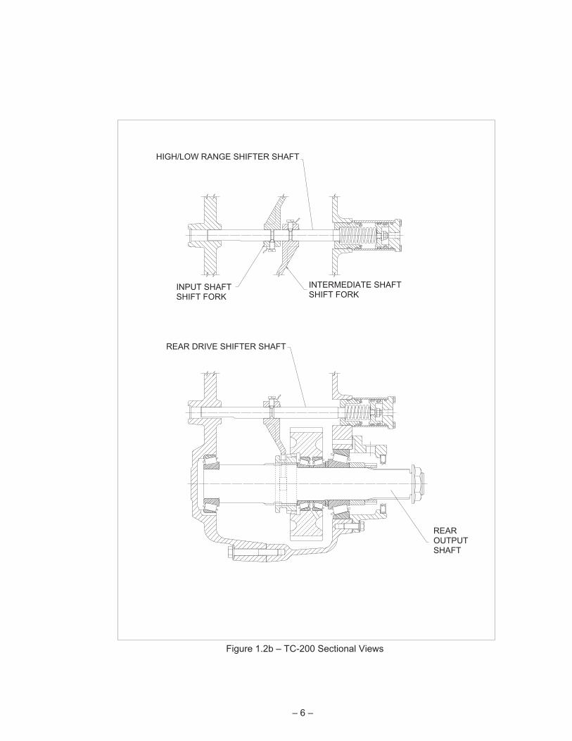
REAROUTPUTSHAFT
REAR DRIVE SHIFTER SHAFT
INTERMEDIATE SHAFTSHIFT FORK
HIGH/LOW RANGE SHIFTER SHAFT
INPUT SHAFTSHIFT FORK
Figure 1.2b – TC-200 Sectional Views

2. LUBRICATION
RECOMMENDED LUBRICANTS
On-Highway Vehicles
1. Heavy-Duty Engine Oil:
Temperature Grade
Above + 10° F SAE 50
Below + 10° F SAE 30
Be sure to specify heavy-duty type meeting MIL-L-2104Bspecifications.
2. Mineral Gear Oil:
Temperature Grade
Above + 10° F SAE 90
Below + 10° F SAE 80
Must be inhibited against corrosion, oxidation, and foam.
Off-Highway & Mining Equipment
1. Heavy-Duty Engine Oil:
Temperature Grade
Above + 10° F SAE 50
Below + 10° F SAE 30
Be sure to specify heavy-duty type meeting MIL-L-2104Bspecifications.
2. Special Recommendation: For extreme coldweather where temperature is consistently below0° F, use SAE 20W heavy-duty engine oil meetingMIL-L-2104B specifications.
NOTE: Extreme pressure (EP) oils are no longer recom-mended for use in Fabco transfer cases. Under certainoperating conditions these oils might form carbon depos-its on gears, shafts or bearings, possibly causing mal-functions and premature failure.
INSPECTION
The oil is to be maintained at the level of the fill plug at alltimes. Check at the following intervals:
Highway Service ....................................1,000 Miles
Off-Highway Service.................................40 Hours
With every oil change, the shift cylinder air lines andvalves should be inspected for leaks and possible mal-functioning. Low pressure conditions can cause partialclutch engagement which may result in premature wearor damage.
OIL CHANGE
The transfer case lubricant should be changed on all newtransfer cases after the first 3,000 to 5,000 miles (on-highway), or the first 40 hours (off-highway); thereafteroil changes should be done at the following intervals:
On-Highway Service .......................10,000-15,000 Miles
Off-Highway Service (Logging, dirt moving, mining, andassociated operations).................... .......500-750 Hours
The recommended oil change and inspection periods arebased on the average use and operating conditions thatthe unit may encounter. It is suggested that the individualowner make a periodic lab analysis of the lubricant todetermine contamination based on the unit's specificoperating conditions. With this data, the oil change andinspection periods can be better determined.
DRAINING THE OIL
Draining is best accomplished after the vehicle has beenoperated briefly, allowing the oil to become warm andflow more freely. Remove both drain and fill plugs. Allowthe housing to empty completely. Before the unit isrefilled, it should be thoroughly flushed with cleanflushing oil or kerosene.
If the unit is equipped with an oil pump, the lube oil filtershould be replaced whenever the oil is changed. Theelement is of the spin-on type. A film of clean oil shouldbe applied to the rubber gasket of the new elementbefore installing. Do not overtighten.
REFILLING THE OIL
If the transfer case has been removed from the vehiclefor service, it is best to refill the oil after the unit has beenreinstalled into the vehicle.
Clean and replace the drain plug and fill the transfer casewith the appropriate oil with the vehicle on level ground.Fill the transfer case to the level of the fill plug.
For each transfer case the oil capacity will vary some-what, depending on the model and the inclination of theunit; therefore, always fill to the level of the fill plug. Donot overfill. Inspect for leaks.
OPERATING TEMPERATURE
The operating temperature of the transfer case shouldnot exceed 250°F (120°C). Extensive operation attemperature exceeding 250° F will result in rapid break-down of the oil and may shorten the transfer case life. Ifreduction of operating speed is not acceptable then thecase may have to be equipped with an external oil coolerto maintain the operating temperature below 250° F.
– 7 –

The following conditions may contribute to excessive oiltemperature.
1. A vehicle remaining stationary for extended periodswhile operating the power take-off.
2. A vehicle which is used in tropical or desert condi-tions.
3. A vehicle where extended body work or an accumu-lation of dirt and plant material may shield the casefrom air ventilation and circulation.
4. A vehicle that is operated for extended distances athigh speed with the main transmission in overdrive.
3. GENERAL INSTRUCTIONS
SAFETY
The servicing and maintenance of components from anyautomotive vehicle present possible hazards and everyendeavor should be made to minimize the risks taken tosuccessfully complete the task. For your protection weoffer these warnings and suggestions:
1. When working on, around, or under the vehicle theparking brake should be securely applied and allwheels should be blocked to prevent wheel move-ment. Do not rely on the vehicle being in gear with adead engine to prevent movement. All work shouldbe performed on a flat level surface free of loose ma-terial.
2. When having to work under a vehicle it should beraised and supported with appropriate frame standsor very secure blocking.
WARNING: Never work under a vehicle while supportedonly on a floor jack or hoist.
3. Be sure any lifting equipment has adequate capacityto raise the vehicle or component being lifted. Thisincludes hydraulic floor jacks, crane type hoists,transmission jacks, and axle support dollies, etc.The weight of Fabco components is given in thespecifications of the applicable service manual.
4. Caution must be exercised when cleaning the com-ponent or underside of the vehicle. Compressed airshould not be used to blow dirt away as any harmfulcontaminant material on the bottom of the vehiclewill be spread around the work area.
Appropriate solvents and cleaning solutions shouldbe used in accordance with their labelling instruc-tions or by referring to the Material Safety Data sheet(MSDS) that is available for each cleaner. Approvedprotective eyewear, gloves, masks and clothingshould always be worn.
5. Fabco has not used Asbestos in any of its productsmanufactured since May of 1989 and was used onlyin axle brake linings prior to that time. See the sepa-
rate Asbestos Warning if you suspect asbestos maybe present on the vehicle or component in the areato be serviced.
REMOVAL FROM VEHICLE
1. Remove fill and lower drain plugs and drain gearlubricant.
2. Disconnect wires leading to indicator light switch,and temperature sensor, if used.
3. Disconnect and tag shift cylinder air lines.
4. Disconnect speedometer wiring.
5. Disconnect drivelines at flanges or yokes.
6. Position a transmission jack of suitable capacitybeneath the transfer case. The transfer case mustbe seated on the jack in a safe and firm position.
7. Disconnect transfer case mountings at rubber shockinsulators. Since mounting designs vary, consultvehicle service manual.
8. After inspecting that all mountings and connectionsto the transfer case are disconnected lower thetransfer case gradually to the floor. It is imperativethat the transfer case is ALWAYS safely positionedon the transmission jack to safeguard the transfercase falling off the jack. Remove the transfer casefrom beneath the vehicle. It may be necessary tojack the truck up to allow room to remove transfercase.
INSTALLATION INTO VEHICLE
1. Place transfer case on transmission jack.
2. Position transmission jack underneath vehicle.Some vehicles may require that one side be jackedup in order to achieve sufficient clearance to replacethe transfer case between the frame rails.
3. Raise the transmission jack to properly locatetransfer case.
4. Connect transfer case mountings. Since mountingdesigns vary, consult vehicle service manual.
5. Connect drivelines.
6. Connect speedometer wiring.
7. Connect shift cylinder air lines.
8. Connect indicator light and temperature sensorwires.
9. Fill housing with appropriate lubricant to correct leveland install fill plug.
10. Check transfer case for leaks around gaskets andseals.
– 8 –

ASBESTOS WARNING
SUGGESTED PROCEDURES FOR WORKING WITH COMPONENTS
SUSPECTED OF CONTAINING ASBESTOS
Asbestos has been found to be a primary cause of various forms of respiratory disease andcancer of several vital body organs. Primary ingestion is by breathing or swallowing dustcontaining fibers and can place smokers at a greater risk than those who do not smoke.The onset of disease can be at an extended period of time, (several years) after the expo-sure. The Occupational and Safety Health Administration (OSHA) has established verystringent limitations for exposure to asbestos fibers by workers using the material, andevery precaution should be taken to minimize the risks involved. The following are somesuggested procedures to adopt when working with material that has, or may be suspectedof containing, asbestos.
1. Approved protective clothing, gloves, eye shield and aprons should be worn wheneverworking around the suspected material. NIOSH & OSHA approved respirator maskssuitable for asbestos dust should be worn at all times. Disposable dust face masks arenot allowed by OSHA.
2. Do not smoke while working on any asbestos related material or wearing protectiveapparel.
3. Do not eat or drink food while wearing protective clothing. Always wash before eating ordrinking.
4. Do not use compressed air for any dirt removal. Use only approved high efficiencyvacuum cleaners suitable for use with asbestos. Do not dry brush deposits or accumula-tions of dirt from components. What cannot be removed with the high efficiency vacuumcleaner should be washed with a water soaked rag. The rag should not be wrung dry butshould be disposed of, together with other wastes containing asbestos in speciallysealed and marked containers in accordance with EPA and OSHA regulations.
5. Do not wear protective clothing away from the working area, vacuum clean clothingbefore removal. Shower, if possible, before going home.
These suggestions are neither complete nor authoritative on the subject of workingwith asbestos but are meant as a warning of possible risk. It is the responsibility ofthe supervising authority to be aware of the possible dangers involved and toprovide suitable training, precaution and protection for those working in an asbes-tos environment.
– 9 –
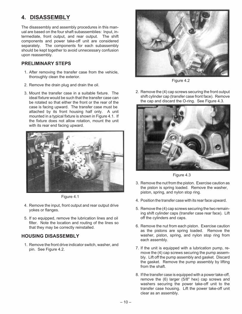
4. DISASSEMBLY
The disassembly and assembly procedures in this man-ual are based on the four shaft subassemblies: Input, in-termediate, front output, and rear output. The shiftcomponents and power take-off unit are consideredseparately. The components for each subassemblyshould be kept together to avoid unnecessary confusionupon reassembly.
PRELIMINARY STEPS
1. After removing the transfer case from the vehicle,thoroughly clean the exterior.
2. Remove the drain plug and drain the oil.
3. Mount the transfer case in a suitable fixture. Theideal fixture would be such that the transfer case canbe rotated so that either the front or the rear of thecase is facing upward. The transfer case must beattached by its front housing half only. A unitmounted in a typical fixture is shown in Figure 4.1. Ifthe fixture does not allow rotation, mount the unitwith its rear end facing upward.
4. Remove the input, front output and rear output driveyokes or flanges.
5. If so equipped, remove the lubrication lines and oilfilter. Note the location and routing of the lines sothat they may be correctly reinstalled.
HOUSING DISASSEMBLY
1. Remove the front drive indicator switch, washer, andpin. See Figure 4.2.
2. Remove the (4) cap screws securing the front outputshift cylinder cap (transfer case front face). Removethe cap and discard the O-ring. See Figure 4.3.
3. Remove the nut from the piston. Exercise caution asthe piston is spring loaded. Remove the washer,piston, spring, and nylon stop ring.
4. Position the transfer case with its rear face upward.
5. Remove the (4) cap screws securing the two remain-ing shift cylinder caps (transfer case rear face). Liftoff the cylinders and caps.
6. Remove the nut from each piston. Exercise cautionas the pistons are spring loaded. Remove thewasher, piston, spring, and nylon stop ring fromeach assembly.
7. If the unit is equipped with a lubrication pump, re-move the (4) cap screws securing the pump assem-bly. Lift off the pump assembly and gasket. Discardthe gasket. Remove the pump assembly by liftingfrom the shaft.
8. If the transfer case is equipped with a power take-off,remove the (6) larger (5/8" hex) cap screws andwashers securing the power take-off unit to thetransfer case housing. Lift the power take-off unitclear as an assembly.
– 10 –
Figure 4.1
Figure 4.2
Figure 4.3
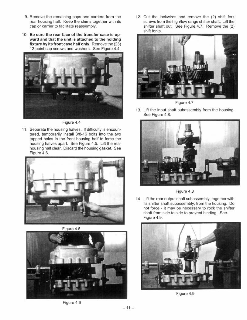
9. Remove the remaining caps and carriers from therear housing half. Keep the shims together with itscap or carrier to facilitate reassembly.
10. Be sure the rear face of the transfer case is up-ward and that the unit is attached to the holdingfixture by its front case half only. Remove the (23)12-point cap screws and washers. See Figure 4.4.
11. Separate the housing halves. If difficulty is encoun-tered, temporarily install 3/8-16 bolts into the twotapped holes in the front housing half to force thehousing halves apart. See Figure 4.5. Lift the rearhousing half clear. Discard the housing gasket. SeeFigure 4.6.
12. Cut the lockwires and remove the (2) shift forkscrews from the high/low range shifter shaft. Lift theshifter shaft out. See Figure 4.7. Remove the (2)shift forks.
13. Lift the input shaft subassembly from the housing.See Figure 4.8.
14. Lift the rear output shaft subassembly, together withits shifter shaft subassembly, from the housing. Donot force - it may be necessary to rock the shiftershaft from side to side to prevent binding. SeeFigure 4.9.
– 11 –
Figure 4.4
Figure 4.5
Figure 4.6
Figure 4.7
Figure 4.8
Figure 4.9

15. Lift the front output shaft subassembly, together withits shifter shaft/fork, from the housing. SeeFigure 4.10.
16. Lift the intermediate shaft subassembly from thecase. See Figure 4.11.
SUBASSEMBLIES
INPUT SHAFT DISASSEMBLY
Refer to Section P.2 in the parts manual.
1. To facilitate reassembly, the gear end float on theshaft should be checked prior to disassembly. Installa dial indicator with a magnetic base as pictured inFigure 4.12. Lift upward on the gear and note theamount of end float. The specified amount of endfloat is between .000 and .002 inches. A greateramount usually indicates worn bearings.
2. Remove the bearing locknut with Fabco Tool866-0687-004 or equivalent. See Section 8.1 in thismanual. Lift off the spacer ring.
3. Place the shaft assembly in a press so that the clutchcollar is supported and the press arbor bears againstthe end of the shaft. Do not support the assemblyby either one of the gears. See Figure 4.13. Re-move the (3) bearing cone assemblies, the gear as-sembly, the two spacer rings, and the clutch collar.
4. Invert the shaft assembly in the press so that theremaining gear is supported. See Figure 4.14.Remove the bearing cone assembly and the gear.Remove the woodruff key if necessary.
– 12 –
Figure 4.12
Figure 4.10
Figure 4.11
Figure 4.13
Figure 4.14

INTERMEDIATE SHAFT DISASSEMBLY
Refer to Section P.3 in the parts manual.
1. To facilitate reassembly, the gear end float on theshaft should be checked prior to disassembly. Installa dial indicator with a magnetic base as pictured inFigure 4.15. Lift upward on the gear and note theamount of end float. The specified amount of endfloat is between .000 and .002 inches. A greateramount usually indicates worn bearings.
2. Remove the bearing locknut with Fabco Tool866-0687-004 or equivalent. See Section 8.1 in thismanual. Lift off the spacer ring.
3. Place the shaft assembly in a press so that the clutchcollar is supported and the press arbor bears againstthe shaft. Do not support the assembly by eitherone of the gears. See Figure 4.16. Remove the (3)bearing cone assemblies, the gear assembly, thespacer ring, and the clutch collar.
4. Invert the shaft assembly in the press so that theremaining gear is supported. See Figure 4.17.Remove the bearing cone assembly and the gear.Remove the woodruff key if necessary.
FRONT OUTPUT SHAFT DISASSEMBLY
Refer to Section P.4 in the parts manual.
1. To facilitate reassembly, the gear end float on theshaft should be checked prior to disassembly. Installa dial indicator with a magnetic base as pictured inFigure 4.18. Lift upward on the gear and note theamount of end float. The specified amount of endfloat is between .000 and .002 inches. A greateramount usually indicates worn bearings.
2. Remove the bearing locknut with Fabco Tool866-0687-004 or equivalent. See Section 8.1 in thismanual. Lift off the spacer ring.
3. Place the shaft assembly in a press so that the clutchcollar is supported and the press arbor bears againstthe end of the shaft. Do not support the assemblyby the gear. See Figure 4.19. Remove the (3) bear-ing cone assemblies, the gear assembly, the (2)spacer rings, and the clutch collar.
– 13 –
Figure 4.17
Figure 4.16
Figure 4.18
Figure 4.15
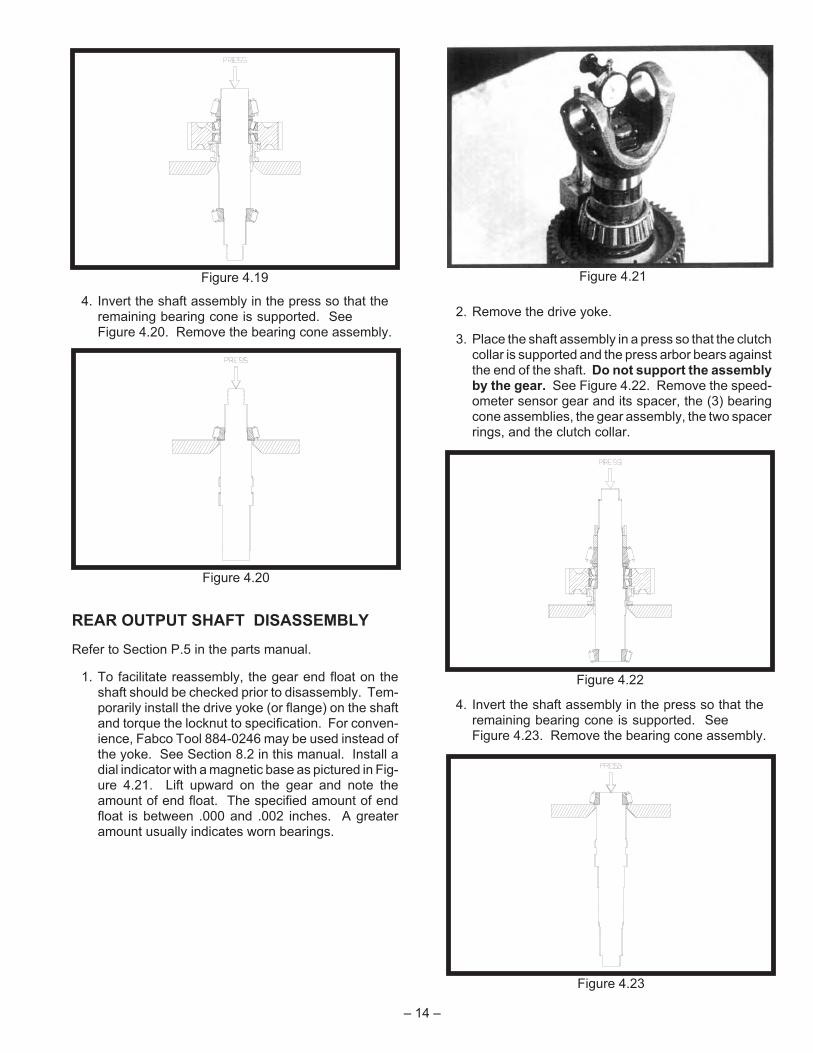
4. Invert the shaft assembly in the press so that theremaining bearing cone is supported. SeeFigure 4.20. Remove the bearing cone assembly.
REAR OUTPUT SHAFT DISASSEMBLY
Refer to Section P.5 in the parts manual.
1. To facilitate reassembly, the gear end float on theshaft should be checked prior to disassembly. Tem-porarily install the drive yoke (or flange) on the shaftand torque the locknut to specification. For conven-ience, Fabco Tool 884-0246 may be used instead ofthe yoke. See Section 8.2 in this manual. Install adial indicator with a magnetic base as pictured in Fig-ure 4.21. Lift upward on the gear and note theamount of end float. The specified amount of endfloat is between .000 and .002 inches. A greateramount usually indicates worn bearings.
2. Remove the drive yoke.
3. Place the shaft assembly in a press so that the clutchcollar is supported and the press arbor bears againstthe end of the shaft. Do not support the assemblyby the gear. See Figure 4.22. Remove the speed-ometer sensor gear and its spacer, the (3) bearingcone assemblies, the gear assembly, the two spacerrings, and the clutch collar.
4. Invert the shaft assembly in the press so that theremaining bearing cone is supported. SeeFigure 4.23. Remove the bearing cone assembly.
– 14 –
Figure 4.21Figure 4.19
Figure 4.20
Figure 4.22
Figure 4.23

5. CLEANING AND INSPECTION
CLEANING
Steam may be used for external cleaning of completelyassembled units. Care must be taken to ensure thatwater is kept out of the assembly by sealing breathercaps and other openings.
Parts should be cleaned with emulsion cleaners or petro-leum solvents. To avoid damage, alkaline solutionsshould not be used.
DRYING AND CORROSION INHIBITION
Dry compressed air or clean, soft shop towels should beused to dry parts after cleaning. Bearings should neverbe spun dry with compressed air.
Dried parts should be immediately coated with a light oilor corrosion inhibitor to prevent corrosion damage. Partswhich are to be stored should also be wrapped in heavywaxed paper or plastic bags and kept dust-free.
INSPECTION
Prior to reassembly, parts which are to be reused must becarefully inspected for signs of wear or damage.Replacement of such parts can prevent costly downtimeat a future date.
All bearing surfaces, including roller bearing cups andcones, should be examined for pitting, wear, or overheat-ing. Gears may also show pits, as well as scoring andbroken teeth. Shafts may be nicked or marred, or havedamaged threads. Parts which show any sign of damageshould be repaired or replaced.
Inspect the rotor, housing, and idler of the oil pump (ifequipped) for scoring. Inspect the drive tab of the rotorassembly. If any damage is noted, the pump cartridgeassembly should be replaced as a unit.
Check all shift forks and slots in sliding clutches for wearor discoloration due to heat. Check the engaging teethfor a partial engagement wear pattern.
6. ASSEMBLY
ASSEMBLY PRECAUTIONS
1. Read the instructions completely before starting re-assembly. Refer to the appropriate exploded view inthe parts manual.
2. All parts must be clean. The gasket surfaces mustbe free of old gasket material. Do not reuse old gas-kets.
3. Bearing cup bores, and shaft spline and bearingmounting surfaces, should be coated with Lubriplateor equivalent. This is necessary to reduce the possi-bility of galling.
4. All used oil seals must be replaced and the new oilseals should be coated with Loctite 601 or equiva-lent on their outer diameter prior to being installed intheir bores. Their sealing lips should be coated withLubriplate or equivalent to provide initial lubrication.
5. Any external cap screw not to be installed in a blindhole should have its threads coated with PermatexForm-A-Gasket #2 or equivalent non-hardeningsealer to prevent an oil leak.
6. All threaded fasteners should be tightened to thetorque specified in the torque chart.
7. Any sharp edges on the seal diameter of the univer-sal joint yoke or companion flanges should beremoved with emery cloth. The seal operating areashould be coated with Lubriplate or equivalent bef-ore installation.
8. In many of the procedures, when a part is assembledwith a press fit, it is recommended that the part beheated prior to installation. The part should beplaced in an oven and heated to no more than 300°F.Excessive heat may change the metallurgical prop-erties of the part. Heated components should be al-lowed to cool to room temperature before end floatmeasurements are made.
CAUTION: Although Fabco does not recommend itsuse in transfer cases, if a formed-in-placegasket is used for repair, extreme cautionmust be exercised to prevent the compoundfrom entering bearings, oil galleries, pas-sages or tapped holes. All beads must bekept smaller than .125 inch diameter.
INPUT SHAFT ASSEMBLY
Refer to Section P.2 in the parts manual.
1. Install the woodruff key. Be sure of the correct key.The input shaft key is 2 inches long while the inter-mediate shaft key is 2 5/16 inches long.
2. Position the shaft as shown in Figure 6.1.
– 15 –
Figure 6.1

3. Heat and install a gear bearing cone assembly (oneof the narrower two) against the shaft shoulder. SeeFigure 6.2.
4. Slide the bearing spacer ring against the cone. Notethat the bearing spacer ring is a select-fit part that isused to adjust the gear end float. If the end floatchecked prior to disassembly was within specifica-tion (.000 to .002 inch) and no parts were replaced,the original bearing spacer ring should provide thecorrect end float upon reassembly.
5. Press the two bearing cups into the gear. Be surethat the cups are seated.
6. Position the gear assembly onto the shaft. The faceof the gear with the internal clutch splines must facedownward. See Figure 6.3.
7. Heat and install the remaining gear bearing coneassembly against the bearing spacer ring. Slide thelarger of the remaining spacer rings against thebearing cone.
8. A fabricated steel sleeve is desirable at this time tocheck the gear end float. See Section 8 in thismanual for construction details. If the construction ofthis sleeve is impractical, skip to step 12, but be sureto check the end float as directed in step 10.
9. Slip the fabricated sleeve over the shaft. Install thebearing locknut with Fabco Tool 866-0687-004 orequivalent. Torque to specification.
10. Install a dial indicator as depicted in Figure 6.4. Liftupward on the gear assembly and note the gear endfloat on the dial indicator. If the end float is not withinspecification (.000 to .002 inch), it will be necessaryto disassemble the shaft by performing Steps 2 and 3under “INPUT SHAFT DISASSEMBLY” in Section 4.Measure the thickness of the original spacer ring andselect a new ring to provide end float within specifica-tion. See item 12 in Section P.2 in the parts manualfor a list of available spacer rings.
1. After the correct end float is obtained, remove thelocknut and the fabricated sleeve.
12. Be sure that the spacer ring is still in place. Heatand install the shaft bearing cone assembly againstthe spacer ring. Slide the remaining spacer ringagainst the bearing cone.
13. Install the bearing locknut with Fabco Tool866-0687-004 or equivalent. Torque to specification.
14. The gear end float should be rechecked at this time.
15. Invert the assembly and install the sliding clutchcollar. The external teeth on the collar must facedownward. See Figure 6.5.
– 16 –
Figure 6.3
Figure 6.2
Figure 6.5
Figure 6.4
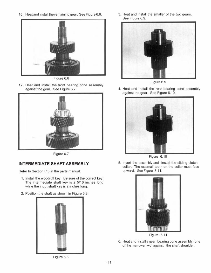
16. Heat and install the remaining gear. See Figure 6.6.
17. Heat and install the front bearing cone assemblyagainst the gear. See Figure 6.7.
INTERMEDIATE SHAFT ASSEMBLY
Refer to Section P.3 in the parts manual.
1. Install the woodruff key. Be sure of the correct key.The intermediate shaft key is 2 5/16 inches longwhile the input shaft key is 2 inches long.
2. Position the shaft as shown in Figure 6.8.
3. Heat and install the smaller of the two gears.See Figure 6.9.
4. Heat and install the rear bearing cone assemblyagainst the gear. See Figure 6.10.
5. Invert the assembly and install the sliding clutchcollar. The external teeth on the collar must faceupward. See Figure 6.11.
6. Heat and install a gear bearing cone assembly (oneof the narrower two) against the shaft shoulder.
– 17 –
Figure 6.9
Figure 6.7
Figure 6.6
Figure 6.8
Figure 6.10
Figure 6.11

7. Slide the bearing spacer ring against the cone. SeeFigure 6.12. Note that the bearing spacer ring is aselect-fit part that is used to adjust the gear end float.If the end float checked prior to disassembly waswithin specification (.000 to .002 inch) and no partswere replaced, the original bearing spacer ringshould provide the correct end float upon reassem-bly.
8. Press the two bearing cups into the gear. Be surethat the cups are seated.
9. Position the gear assembly onto the shaft. The faceof the gear with the internal clutch splines must facedownward. Heat and install the remaining gearbearing cone assembly against the bearing spacerring. See Figure 6.13.
10. A fabricated steel sleeve is desirable at this time tocheck the gear end float. See Section 8 in thismanual for construction details. If the construction ofthis sleeve is impractical, skip to step 14, but be sureto check the end float as directed in Step 12.
11. Slip the fabricated sleeve over the shaft. Install thebearing locknut with Fabco Tool 866-0687-004 orequivalent. Torque to specification.
12. Install a dial indicator as depicted in Figure 6.14. Liftupward on the gear assembly and note the gear endfloat on the dial indicator. If the end float is not withinspecification (.000 to .002 inch), it will be necessaryto disassemble the shaft by performing Steps 2 and 3under “INTERMEDIATE SHAFT DISASSEMBLY” inSection 4. Measure the thickness of the originalspacer ring and select a new ring to provide end floatwithin the specification. See item 8 in Section P.3 orP.4 in the parts manual for a list of available spacerrings.
13. After the correct end float is obtained, remove thelocknut and the fabricated sleeve.
14. Heat and install the shaft bearing cone assemblyagainst the gear bearing cone. Slide the remainingspacer ring against the bearing cone.
15. Install the bearing locknut with Fabco Tool866-0687-004 or equivalent. Torque to specification.
16. The gear end float should be rechecked at this time.
FRONT OUTPUT SHAFT ASSEMBLY
Refer to Section P.4 in the parts manual.
1. Heat and install the front bearing cone assemblyagainst the shaft shoulder. After the bearing cools toroom temperature, position the shaft as shown inFigure 6.15.
– 18 –
Figure 6.14
Figure 6.15
Figure 6.12
Figure 6.13

2. With its external teeth facing upward, slip the clutchcollar over the shaft as shown in Figure 6.16.
3. Heat and install a gear bearing cone assembly (oneof the narrower two) against the shaft shoulder. SeeFigure 6.17.
4. Slide the bearing spacer ring against the cone. Notethat the bearing spacer ring is a select-fit part that isused to adjust the gear end float. If the end floatchecked prior to disassembly was within specifica-tion (.000 to .002 inch) and no parts were replaced,the original bearing spacer ring should provide thecorrect end float upon reassembly.
5. Press the two bearing cups into the gear. Be surethat the cups are seated.
6. Position the gear assembly onto the shaft. The faceof the gear with the internal clutch splines must facedownward.
7. Heat and install the remaining gear bearing coneassembly against the bearing spacer ring. Slide thelarger of the remaining spacer rings against thebearing cone. See Figure 6.18.
8. A fabricated steel sleeve is desirable at this time tocheck the gear end float. See Section 8 in this man-ual for construction details. If the construction of thissleeve is impractical, skip to Step 12, but be sure tocheck the end float as directed in Step 10.
9. Slip the fabricated sleeve over the shaft. Install thebearing locknut with Fabco Tool 866-0687-004 orequivalent. Torque to specification.
10. Install a dial indicator as depicted in Figure 6.19. Liftupward on the gear assembly and note the gear endfloat on the dial indicator. If the end float is not withinspecification (.000 to .002 inch), it will be necessaryto disassemble the shaft by performing Steps 2 and3 under “FRONT OUTPUT SHAFT DISASSEMBLY”in Section 4. Measure the thickness of the originalspacer ring and select a new ring to provide end floatwithin specification. See item 10 in Section P.5 inthe parts manual for a list of available spacer rings.Be sure to recheck the gear end float after a newspacer ring is installed.
11. After the correct end float is obtained, remove thelocknut and the fabricated sleeve.
12. Be sure that the spacer ring is still in place. Heatand install the shaft bearing cone assembly againstthe spacer ring. Slide the remaining spacer ringagainst the bearing cone.
– 19 –
Figure 6.18
Figure 6.17
Figure 6.16
Figure 6.19

13. Install the bearing locknut with Fabco Tool866-0687-004 or equivalent. Torque tospecification.
14. The gear end float should be rechecked at this time.
REAR OUTPUT SHAFT ASSEMBLY
Refer to Section P.5 in the parts manual.
1. Heat and install the front bearing cone assemblyagainst the shaft shoulder. After the bearing cools toroom temperature, position the shaft with the bear-ing downward.
2. With its external teeth facing upward, slip the clutchcollar over the shaft as shown in Figure 6.20.
3. Heat and install a gear bearing cone assembly (oneof the narrower two) against the shaft shoulder.
4. Slide the bearing spacer ring against the cone. SeeFigure 6.21. Note that the bearing spacer ring is aselect-fit part that is used to adjust the gear end float.If the end float checked prior to disassembly waswithin specification (.000 to .002 inch) and no partswere replaced, the original bearing spacer ringshould provide the correct end float upon reassem-bly.
5. Press the two bearing cups into the gear. Be surethat the cups are seated.
6. Position the gear assembly onto the shaft. The faceof the gear with the internal clutch spline must facedownward. See Figure 6.22.
7. Heat and install the remaining gear bearing coneassembly against the bearing spacer ring. Slide thethin spacer ring against the bearing cone. SeeFigure 6.23.
8. A fabricated steel sleeve is desirable at this time tocheck the gear end float. See Section 8 in this man-ual for construction details. If the construction of thissleeve is impractical, perform Step 12, and then tem-porarily install the yoke or flange (or Fabco Tool884-0246) and check the end float as directed inStep 10.
9. Slip the fabricated sleeve over the shaft. Install theyoke retaining nut and torque to specifications.
– 20 –
Figure 6.22
Figure 6.21
Figure 6.20
Figure 6.23
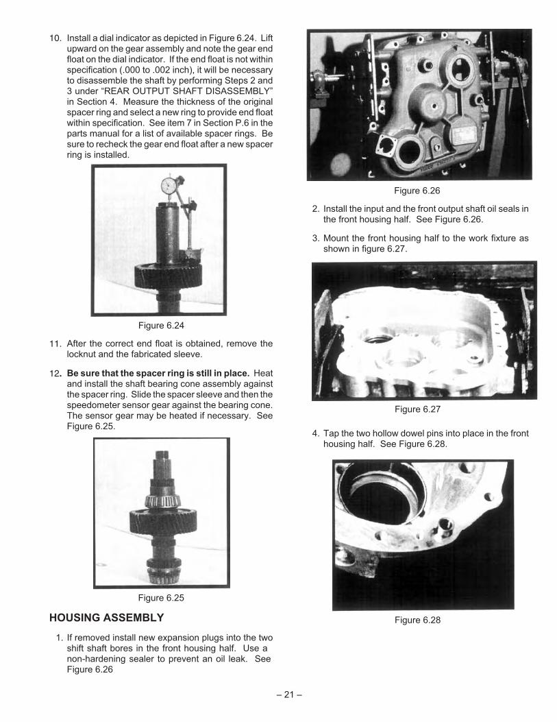
10. Install a dial indicator as depicted in Figure 6.24. Liftupward on the gear assembly and note the gear endfloat on the dial indicator. If the end float is not withinspecification (.000 to .002 inch), it will be necessaryto disassemble the shaft by performing Steps 2 and3 under “REAR OUTPUT SHAFT DISASSEMBLY”in Section 4. Measure the thickness of the originalspacer ring and select a new ring to provide end floatwithin specification. See item 7 in Section P.6 in theparts manual for a list of available spacer rings. Besure to recheck the gear end float after a new spacerring is installed.
11. After the correct end float is obtained, remove thelocknut and the fabricated sleeve.
12. Be sure that the spacer ring is still in place. Heatand install the shaft bearing cone assembly againstthe spacer ring. Slide the spacer sleeve and then thespeedometer sensor gear against the bearing cone.The sensor gear may be heated if necessary. SeeFigure 6.25.
HOUSING ASSEMBLY
1. If removed install new expansion plugs into the twoshift shaft bores in the front housing half. Use anon-hardening sealer to prevent an oil leak. SeeFigure 6.26
2. Install the input and the front output shaft oil seals inthe front housing half. See Figure 6.26.
3. Mount the front housing half to the work fixture asshown in figure 6.27.
4. Tap the two hollow dowel pins into place in the fronthousing half. See Figure 6.28.
– 21 –
Figure 6.25
Figure 6.26
Figure 6.24
Figure 6.27
Figure 6.28

5. Install the (4) bearing cups into the inside of the fronthousing half. See Figure 6.29.
6. Lower the intermediate shaft subassembly intoplace (larger gear down). See Figure 6.30.
7. Position the front output shift shaft/fork to the frontoutput shaft clutch collar and lower into place (gearend upward). See Figure 6.31.
8. Assemble the rear output shift fork to the shift shaft,observing the orientation depicted in Figure 6.32.Install the fork locking screw. Be sure that the screwis seated in the shaft groove. Torque to specificationand lockwire to the shaft as shown in Figure 6.32.
9. Position the rear output shift shaft/fork subassemblyto the rear output shaft clutch collar and lower intoplace. See Figure 6.33.
10. Lower the input shaft subassembly into place(smaller gear downward). See Figure 6.34.
– 22 –
Figure 6.29
Figure 6.30
Figure 6.31
Figure 6.32
Figure 6.33
Figure 6.34

11. Position a shift fork to the input shaft clutch collar andthe remaining shift fork to the intermediate shaftclutch collar observing the directions as in Figure6.35. Locate the shift fork bores in line with the shaftbore in the front housing half.
12. Insert the high/low range shift shaft through thebores in the shift forks and into the bore in the fronthousing (threaded end of the shaft upward). SeeFigure 6.36.
13. Install the input shaft shift fork locking screw andtorque to specification. Be sure that the screw isseated in the lower groove. Rotate both shift forksclockwise until no further movement is possible.Install the intermediate shaft shift fork locking screwand torque to specification, insuring that the screw isseated in its groove. Attempt to rotate the shift shaftback and forth. There should be some obvious freeplay. Lockwire the two screws as shown inFigure 6.37.
14. Gently tap the four bearing cups into the rear casehalf bores. See Figure 6.38.
15. Place a new housing gasket over the two hollowdowel pins and lower the rear housing half intoplace. Secure with two of the 4 inch long hex headbolts at the pin locations. The remaining 4 inch longbolt is to be used with the lifting bracket at the loca-tion pictured in Figure 1.1. Use two flat washersbetween the bracket and the housing. Install theremaining (18) bolts. Torque all (21) bolts to specifi-cation in a criss-cross sequence.
In the steps that follow, a selected shim pack is usedto adjust the end float of each of the assemblies. Thecorrect setting is .003 to .008 inches. See theparts manual for a list of available shims.
Temporary guide studs may be used to assist inlocating the shims and the cap or carrier. To makethe studs, cut the heads off of two 7/16-14 x 2 inchlong cap screws.
– 23 –
Figure 6.35
Figure 6.37
Figure 6.36
Figure 6.38
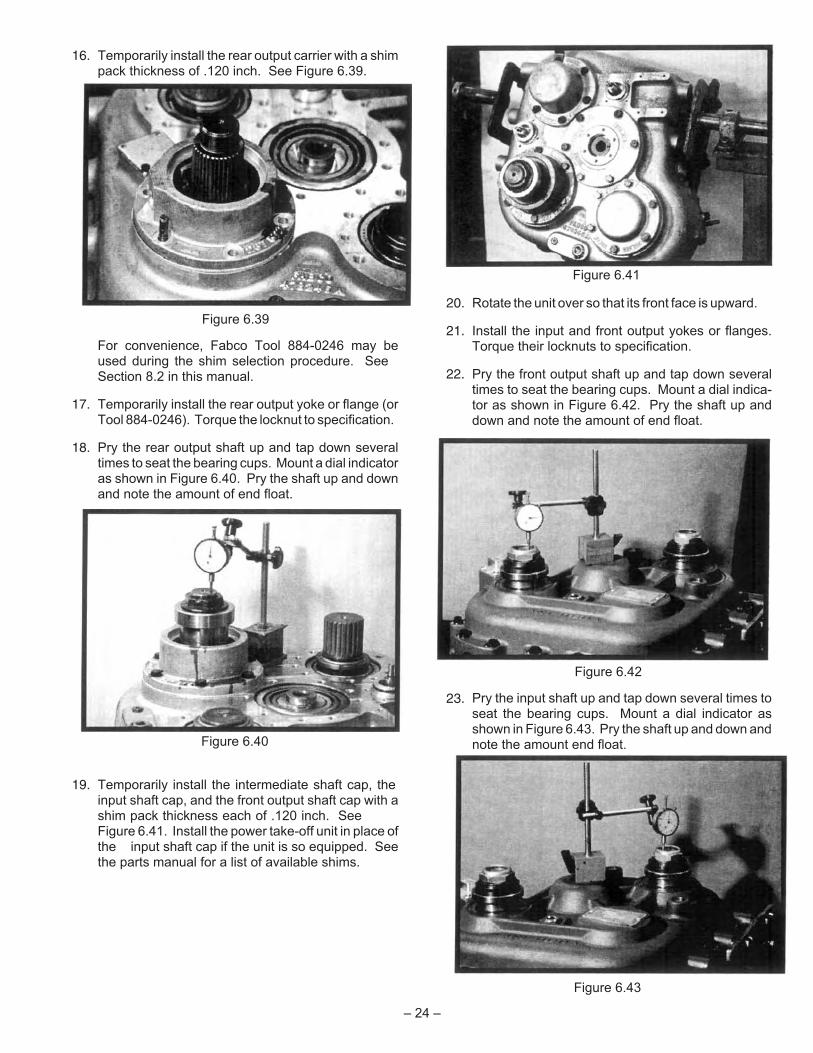
16. Temporarily install the rear output carrier with a shimpack thickness of .120 inch. See Figure 6.39.
For convenience, Fabco Tool 884-0246 may beused during the shim selection procedure. SeeSection 8.2 in this manual.
17. Temporarily install the rear output yoke or flange (orTool 884-0246). Torque the locknut to specification.
18. Pry the rear output shaft up and tap down severaltimes to seat the bearing cups. Mount a dial indicatoras shown in Figure 6.40. Pry the shaft up and downand note the amount of end float.
19. Temporarily install the intermediate shaft cap, theinput shaft cap, and the front output shaft cap with ashim pack thickness each of .120 inch. SeeFigure 6.41. Install the power take-off unit in place ofthe input shaft cap if the unit is so equipped. Seethe parts manual for a list of available shims.
20. Rotate the unit over so that its front face is upward.
21. Install the input and front output yokes or flanges.Torque their locknuts to specification.
22. Pry the front output shaft up and tap down severaltimes to seat the bearing cups. Mount a dial indica-tor as shown in Figure 6.42. Pry the shaft up anddown and note the amount of end float.
23. Pry the input shaft up and tap down several times toseat the bearing cups. Mount a dial indicator asshown in Figure 6.43. Pry the shaft up and down andnote the amount end float.
– 24 –
Figure 6.41
Figure 6.40
Figure 6.39
Figure 6.42
Figure 6.43

24. Working through the breather elbow hole in the fronthousing and the opening in the rear intermediateshaft cap, tap the intermediate shaft up and downseveral times to seat the bearing cups. Make surethat the shaft is all the way down before proceeding.
25. Install a dial indicator such that its probe is restingagainst the front of the intermediate shaft throughthe breather elbow hole. See Figure 6.44.
26. Push upward on the intermediate shaft and note theamount of end float on the dial indicator.
27. Repeat steps 24 through 26 several times to be sureof consistent results.
28. Assemble the front output shift cylinder as follows:Install a new piston-to-shaft O-ring over the threadedportion of the shifter shaft. Slip the spring over theshaft. Insert the nylon stop ring into the cylinderbore. See Figure 6.45.
29. Install the piston O-ring in the deeper groove in thefront output piston. Soak the felt strip in gear oil andinstall in the other groove. Insert the piston into itsbore. The end of the piston with the felt strip must goin first. See Figure 6.46. Install the washer and nutover the piston. Torque the nut to specification.
30. Install a new O-ring on the shift cylinder cap. Installthe cap such that the air inlet port points away fromthe front output shaft. See Figure 6.47. Torque thefour cap screws to specification.
31. Insert the front drive indicator switch actuating pininto place. The rounded end of the pin must faceinward. See Figure 6.48. Install the switch using anew copper washer and torque to specification.
– 25 –
Figure 6.46
Figure 6.44
Figure 6.45
Figure 6.47
Figure 6.48

32. At this point, it is advantageous to verify the opera-tion of the shift indicator switch. Apply and releaseshop air (150 psi maximum) to the shift cylinder whileobserving switch operation with a continuity tester.See Figure 6.49. It may be necessary to rotate thegear train slightly to permit clutch engagement.
33. Install the breather vent and elbow in the fronthousing. The vent must point toward the top of thetransfer case. See Figure 6.50.
34. Rotate the transfer case over so that its rear end isfacing upward.
35. Remove the rear output yoke or flange (or Tool844-0246).
36. Remove the rear output carrier, the front output shaftcap, the intermediate shaft cap, and the input shaftcap (or power take-off unit).
37. To determine each correct shim pack thickness,subtract the measured amount of end play from theshim pack thickness used (.120 inch). The result ofthe subtraction is the shim pack thickness that wouldprovide for zero end float of the shaft. Select a com-bination of shims to add up to as close as possible tothis amount.
See the parts manual for a list of available shims.Since the thinnest shim available is .002 inch thick,the shim pack may be plus or minus .001 inch fromthe desired amount. If this procedure is carefullyfollowed, the shaft end float after reassembly shouldbe within the specified range of .003 to .008 inches.Always recheck the final end float with the dialindicator.
38. Press the oil seal into the rear output carrier (Figure6.51) and install on the transfer case using the shimpack determined in Step 37.
39. Install the intermediate shaft cap, the front outputshaft cap, and the input shaft cap (or power take-offunit) using the respective shim pack determined inStep 37. When installing the input shaft cap, use thelifting bracket in place of the washer at the upper-most location. See Figure 6.52. Torque the (18) capscrews to specification.
40. If the unit is not equipped with a lubrication pump,install the blanking cap with a new gasket on theintermediate shaft cap. Torque the (6) cap screws tospecification. See Figure 6.53.
If the unit is equipped with a lubrication pump, followthe lubrication pump installation instructionscontained in the PTO conversion kit.
– 26 –
Figure 6.51
Figure 6.49
Figure 6.50
Figure 6.52

41. Assemble the high/low range air shift cylinder asfollows: Install two new O-rings on the shift cylinderadapter tube and push into the rear transfer casehousing bore. See Figure 6.54. The end of the tubewith the counterbore must face outward.
42. Install a new piston-to-shaft O-ring over the threadedportion of the shaft. Slide the spring over the shaft.Note that this spring is longer than the rear outputshift spring. Place the nylon stop ring over the shaftand spring.
43. Install a new piston O-ring in the deeper groove inthe piston. Position the piston on the shifter shaft.The end of the piston with the O-ring must faceoutward. Push the piston down to compress thespring and install the shifter shaft washer andlocknut. See Figure 6.55. Torque the nut to specifi-cation.
44. Soak the felt strip in gear oil and install in its grooveon the piston. Slip the air shift cylinder into positionover the piston. See Figure 6.56. Note that thiscylinder is longer than the rear output shift cylinder.
45. Install a new O-ring on the shift cylinder cap andinsert into the cylinder. Secure the assembly withthe (4) cap screws and torque to specification. SeeFigure 6.57.
46. Assemble the rear output air shift cylinder similarly.
47. If so equipped, install the lubrication lines and a newfilter.
– 27 –
Figure 6.53 Figure 6.55
Figure 6.54
Figure 6.56
Figure 6.57

NOTES:
– 28 –

15
FRONTOUTPUTSHAFT
INPUT SHAFT
45
OPTIONALLUBRICATIONPUMP
INTERMEDIATESHAFT
25 25
45
FRONT DRIVE SHIFTER SHAFT
45
15
15
7
45
45
ALL SPECIFIED TORQUE VALUES ARE IN LB-FT AND AREFOR DRY, NON-LUBRICATED THREADS. RECOMMENDEDTORQUES ARE WITHIN 10% OF THE VALUES SHOWN.
30
60
25
25
Figure 7.1 - TC-200 Recommended Torques
30
15
REAROUTPUTSHAFT
HIGH/LOW RANGE SHIFTER SHAFT
30
15
REAR DRIVE SHIFTER SHAFT
60
45
–29
–

–30
–
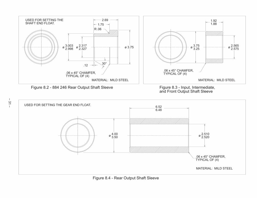
MATERIAL: MILD STEEL
2.69
1.75
ø3.0032.998
ø2.3172.327
ø 3.75
.06 x 45° CHAMFER,TYPICAL OF (4)
MATERIAL: MILD STEEL
R .06
30°.12
.06 x 45° CHAMFER,TYPICAL OF (4)
ø2.5652.575
ø3.753.25
1.921.88
6.526.48
ø2.5102.520
ø4.003.50
.06 x 45° CHAMFER,TYPICAL OF (4)
MATERIAL: MILD STEEL
USED FOR SETTING THESHAFT END FLOAT.
USED FOR SETTING THE GEAR END FLOAT.
Figure 8.4 - Rear Output Shaft Sleeve
Figure 8.2 - 884 246 Rear Output Shaft Sleeve Figure 8.3 - Input, Intermediate,and Front Output Shaft Sleeve
–31
–


