20
TC-3300 Temperature Controller Product Information Packet

TC-3300 Temperature Controller Product Information Packet

2/20
3/20
Table of Contents 1 INTRODUCTION ..................................................................................................................4 2 SPECIFICATIONS................................................................................................................5 2.1 Main Features ..................................................................................................................5 2.2 General Specifications....................................................................................................5 2.3 Part Numbers...................................................................................................................6 3 DIMENSIONS, PANEL CUTOUT AND MOUNTING ............................................................7 3.1 Dimensions ......................................................................................................................7 3.2 Panel Cutout ....................................................................................................................7 3.3 Mounting ..........................................................................................................................8 4 ELECTRICAL INSTALLATION AND SENSORS.................................................................8 4.1 Electrical Installation ......................................................................................................8 4.2 Sensors ............................................................................................................................9 5 PROGRAMS....................................................................................................................... 10 5.1 Factory (Preset) Program ............................................................................................. 10 5.2 Basic On-Off Program................................................................................................... 11 5.3 PID Style with Auto Tune .............................................................................................. 12 5.4 Heat/Cool Program for Enclosure Application ........................................................... 13 5.5 Cool Only Program for Enclosure Application ........................................................... 14 6 EXTERNAL RELAYS (applies only to the models with external relays)............................. 15 6.1 Relay Block Mounting................................................................................................... 16 6.2 Relay Block Wiring........................................................................................................ 17 7 RS-232 AND RS-485 COMMUNICATIONS ....................................................................... 18 7.1 CALCOMMS Software ................................................................................................... 18 7.2 PC Requirements for CALCOMMS............................................................................... 18 7.3 MODBUS RTU Protocols .............................................................................................. 18 8 WARRANTY ....................................................................................................................... 19
4/20
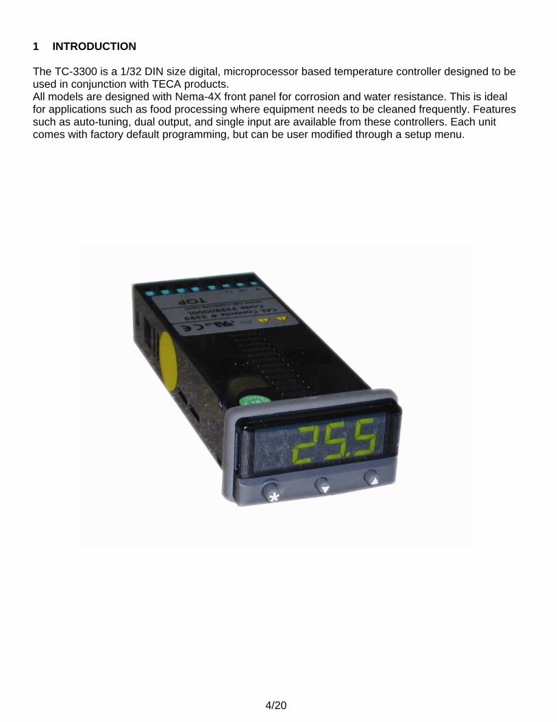
1 INTRODUCTION The TC-3300 is a 1/32 DIN size digital, microprocessor based temperature controller designed to be used in conjunction with TECA products. All models are designed with Nema-4X front panel for corrosion and water resistance. This is ideal for applications such as food processing where equipment needs to be cleaned frequently. Features such as auto-tuning, dual output, and single input are available from these controllers. Each unit comes with factory default programming, but can be user modified through a setup menu.
5/20
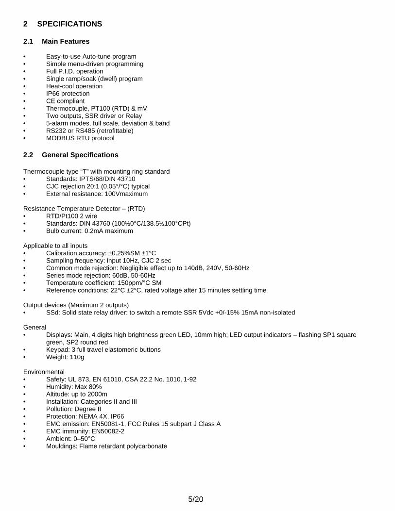
2 SPECIFICATIONS 2.1 Main Features • Easy-to-use Auto-tune program • Simple menu-driven programming • Full P.I.D. operation • Single ramp/soak (dwell) program • Heat-cool operation • IP66 protection • CE compliant • Thermocouple, PT100 (RTD) & mV • Two outputs, SSR driver or Relay • 5-alarm modes, full scale, deviation & band • RS232 or RS485 (retrofittable) • MODBUS RTU protocol 2.2 General Specifications Thermocouple type “T” with mounting ring standard • Standards: IPTS/68/DIN 43710 • CJC rejection 20:1 (0.05°/°C) typical • External resistance: 100Vmaximum Resistance Temperature Detector – (RTD) • RTD/Pt100 2 wire • Standards: DIN 43760 (100½0°C/138.5½100°CPt) • Bulb current: 0.2mA maximum Applicable to all inputs • Calibration accuracy: ±0.25%SM ±1°C • Sampling frequency: input 10Hz, CJC 2 sec • Common mode rejection: Negligible effect up to 140dB, 240V, 50-60Hz • Series mode rejection: 60dB, 50-60Hz • Temperature coefficient: 150ppm/°C SM • Reference conditions: 22°C ±2°C, rated voltage after 15 minutes settling time Output devices (Maximum 2 outputs) • SSd: Solid state relay driver: to switch a remote SSR 5Vdc +0/-15% 15mA non-isolated General • Displays: Main, 4 digits high brightness green LED, 10mm high; LED output indicators – flashing SP1 square
green, SP2 round red • Keypad: 3 full travel elastomeric buttons • Weight: 110g Environmental • Safety: UL 873, EN 61010, CSA 22.2 No. 1010. 1-92 • Humidity: Max 80% • Altitude: up to 2000m • Installation: Categories II and III • Pollution: Degree II • Protection: NEMA 4X, IP66 • EMC emission: EN50081-1, FCC Rules 15 subpart J Class A • EMC immunity: EN50082-2 • Ambient: 0–50°C • Mouldings: Flame retardant polycarbonate
6/20
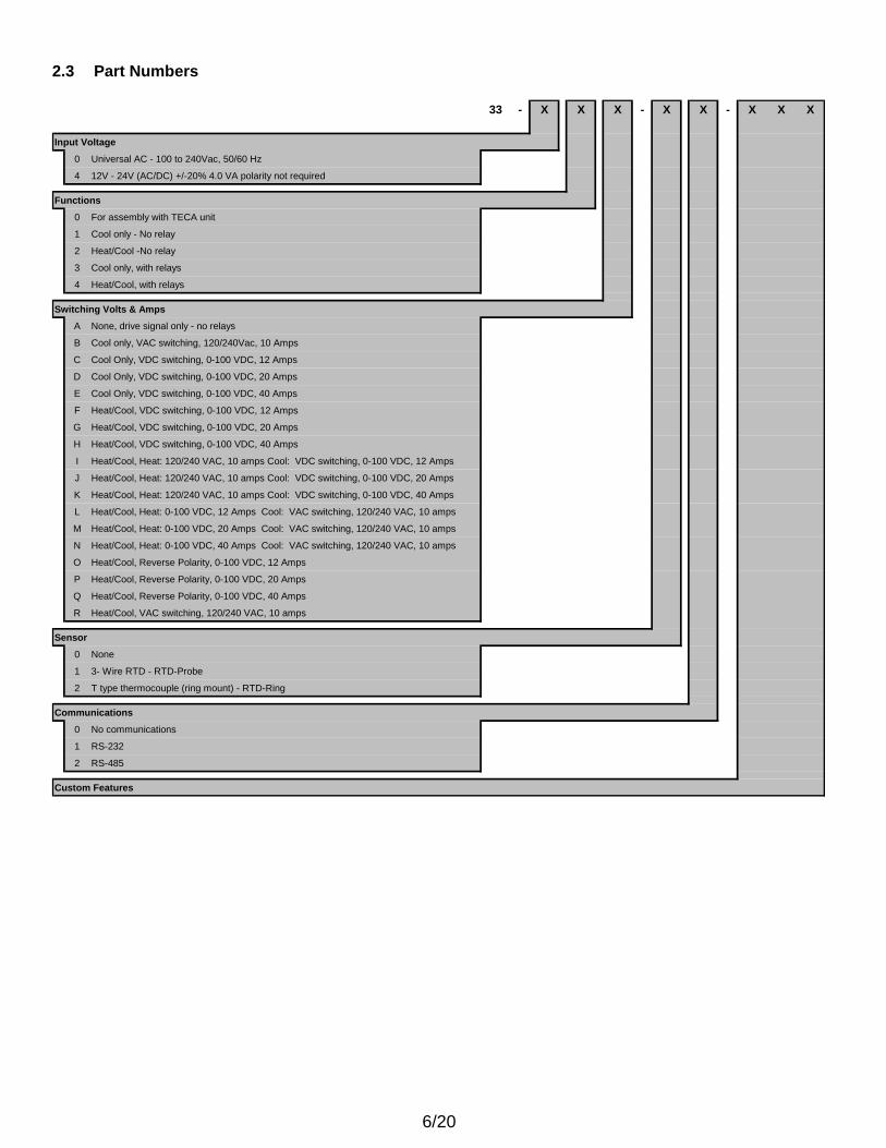
2.3 Part Numbers
33 - X X X - X X - X X X
Input Voltage
0 Universal AC - 100 to 240Vac, 50/60 Hz
4 12V - 24V (AC/DC) +/-20% 4.0 VA polarity not required
Functions
0 For assembly with TECA unit
1 Cool only - No relay
2 Heat/Cool -No relay
3 Cool only, with relays
4 Heat/Cool, with relays
Switching Volts & AmpsA None, drive signal only - no relays
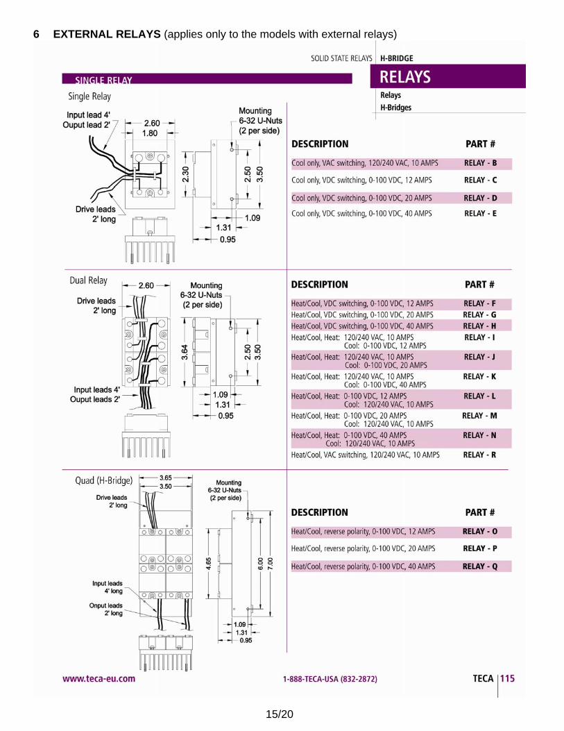
B Cool only, VAC switching, 120/240Vac, 10 Amps
C Cool Only, VDC switching, 0-100 VDC, 12 Amps
D Cool Only, VDC switching, 0-100 VDC, 20 Amps
E Cool Only, VDC switching, 0-100 VDC, 40 Amps
F Heat/Cool, VDC switching, 0-100 VDC, 12 Amps
G Heat/Cool, VDC switching, 0-100 VDC, 20 Amps
H Heat/Cool, VDC switching, 0-100 VDC, 40 Amps
I Heat/Cool, Heat: 120/240 VAC, 10 amps Cool: VDC switching, 0-100 VDC, 12 Amps
J Heat/Cool, Heat: 120/240 VAC, 10 amps Cool: VDC switching, 0-100 VDC, 20 Amps
K Heat/Cool, Heat: 120/240 VAC, 10 amps Cool: VDC switching, 0-100 VDC, 40 Amps
L Heat/Cool, Heat: 0-100 VDC, 12 Amps Cool: VAC switching, 120/240 VAC, 10 amps
M Heat/Cool, Heat: 0-100 VDC, 20 Amps Cool: VAC switching, 120/240 VAC, 10 amps
N Heat/Cool, Heat: 0-100 VDC, 40 Amps Cool: VAC switching, 120/240 VAC, 10 amps
O Heat/Cool, Reverse Polarity, 0-100 VDC, 12 Amps
P Heat/Cool, Reverse Polarity, 0-100 VDC, 20 Amps
Q Heat/Cool, Reverse Polarity, 0-100 VDC, 40 Amps
R Heat/Cool, VAC switching, 120/240 VAC, 10 amps
Sensor
0 None
1 3- Wire RTD - RTD-Probe
2 T type thermocouple (ring mount) - RTD-Ring
Communications
0 No communications
1 RS-232
2 RS-485
Custom Features
7/20
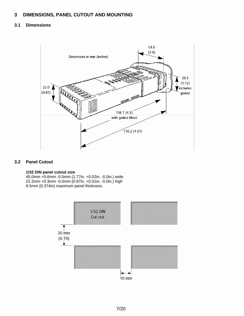
3 DIMENSIONS, PANEL CUTOUT AND MOUNTING 3.1 Dimensions 3.2 Panel Cutout
1/32 DIN panel cutout size 45.0mm +0.6mm -0.0mm (1.77in. +0.02in. -0.0in.) wide 22.2mm +0.3mm -0.0mm (0.87in. +0.01in. -0.0in.) high 9.5mm (0.374in) maximum panel thickness.
8/20
3.3 Mounting The TC-3300 Controller is designed to be mounted in a 1/32 DIN panel cutout. The TC-3300 sleeve mounted with it’s front bezel assembly rated NEMA4/IP66 provided that:
• the panel is smooth and the panel cutout is accurate • the mounting instructions are carefully followed
To mount the controller proceed as follows:
1. Check that the controller is correctly orientated and then slide the unit into the cutout.
2. Slide the panel clamp over the controller sleeve pressing it firmly against the panel until the controller is held firmly.
3. The controller front bezel and circuit board assembly can be unplugged from the sleeve. Grasp the bezel firmly
by the recesses on each side and pull. A screwdriver can be used as a lever if required.
4. When refitting the bezel assembly it is important to press it firmly into the sleeve until the latch clicks in order to compress the gasket and seal to NEMA4X/IP66.
Note: The controller should be isolated before removing or refitting it in the sleeve, and electrostatic precautions should
be observed when handling the controller outside the sleeve. The controller should be wired only after it is mounted in the panel. The controller can not fit through the panel cutout with wires attached to it.
4 ELECTRICAL INSTALLATION AND SENSORS 4.1 Electrical Installation Please refer to the appropriate wiring diagram included with the product package. The TC-3300 is designed for use with the following supply voltages:
• 100 - 240V 50-60 Hz 4.0 VA (nominal) +/-10% maximum permitted fluctuation • 12V - 24V (AC/DC) +/-20% 4.0 VA Polarity not required
Wiring the connector: Prepare the cable carefully, remove a maximum of 8mm insulation and ideally tin to avoid bridging. Prevent excessive cable strain. Maximum recommended wire size: 32/0.2mm 1.0mm2 (18AWG). EN61010 - /CSA 22.2 No 1010.1 92 Compliance shall not be impaired when fitted to the final installation. Designed to offer a minimum of Basic Insulation only. The body responsible for the installation is to ensure that supplementary insulation suitable for Installation Category II or III is achieved when fully installed. To avoid possible hazards, accessible conductive parts of the final installation should be protectively earthed in accordance with EN6010 for Class 1 Equipment. Output wiring should be within a Protectively Earthed cabinet. Sensor sheaths should be bonded to protective earth or not be accessible. Live parts should not be accessible without the use of a tool. When fitted to the final installation, an IEC/CSA APPROVED disconnecting device should be used to disconnect both LINE and NEUTRAL conductors simultaneously. A clear instruction shall be provided not to position the equipment so that it is difficult to operate the disconnecting device.
9/20
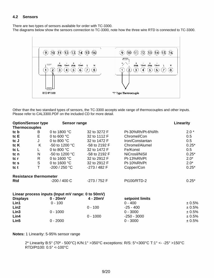
4.2 Sensors There are two types of sensors available for order with TC-3300. The diagrams below show the sensors connection to TC-3300, note how the three wire RTD is connected to TC-3300.
Other than the two standard types of sensors, the TC-3300 accepts wide range of thermocouples and other inputs. Please refer to CAL3300.PDF on the included CD for more detail. Option/Sensor type Sensor range Linearity Thermocouples tc b B 0 to 1800 °C 32 to 3272 F Pt-30%Rh/Pt-6%Rh 2.0 * tc E E 0 to 600 °C 32 to 1112 F Chromel/Con 0.5 tc J J 0 to 800 °C 32 to 1472 F Iron/Constantan 0.5 tc K K -50 to 1200 °C -58 to 2192 F Chromel/Alumel 0.25* tc L L 0 to 800 °C 32 to 1472 F Fe/Konst 0.5 tc n N -50 to 1200 °C -58 to 2192 F NiCrosil/NiSil 0.25* tc r R 0 to 1600 °C 32 to 2912 F Pt-13%Rh/Pt 2.0* tc s S 0 to 1600 °C 32 to 2912 F Pt-10%Rh/Pt 2.0* tc t T -200 / 250 °C -273 / 482 F Copper/Con 0.25* Resistance thermometer Rtd -200 / 400 C -273 / 752 F Pt100/RTD-2 0.25* Linear process inputs (Input mV range: 0 to 50mV) Displays 0 - 20mV 4 - 20mV setpoint limits Lin1 0 - 100 0 - 400 ± 0.5% Lin2 0 - 100 -25 - 400 ± 0.5% Lin3 0 - 1000 0 - 3000 ± 0.5% Lin4 0 - 1000 -250 - 3000 ± 0.5% Lin5 0 - 2000 0 - 3000 ± 0.5% Notes: 1 Linearity: 5-95% sensor range
2* Linearity B:5° (70º - 500°C) K/N:1° >350°C exceptions: R/S: 5°<300°C T:1° <- -25° >150°C RTD/Pt100: 0.5° <-100°C
10/20
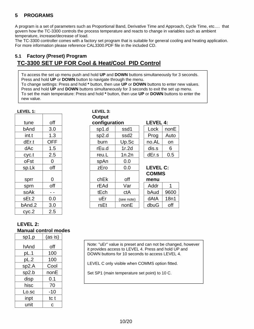
5 PROGRAMS A program is a set of parameters such as Proportional Band, Derivative Time and Approach, Cycle Time, etc…. that govern how the TC-3300 controls the process temperature and reacts to change in variables such as ambient temperature, increase/decrease of load. The TC-3300 controller comes with a factory set program that is suitable for general cooling and heating application. For more information please reference CAL3300.PDF file in the included CD. 5.1 Factory (Preset) Program TC-3300 SET UP FOR Cool & Heat/Cool PID Control LEVEL 1: LEVEL 3:
tune off Output configuration LEVEL 4:
bAnd 3.0 sp1.d ssd1 Lock nonE int.t 1.3 sp2.d ssd2 Prog Auto dEr.t OFF burn Up.Sc no.AL on dAc 1.5 rEu.d 1r.2d dis.s 6 cyc.t 2.5 reu.L 1n.2n dEr.s 0.5 oFst 0 spAn 0.0 sp.Lk off zEro 0.0 LEVEL C:
sprr 0 chEk off COMMS menu
sprn off rEAd Var Addr 1 soAk - - tEch ctA bAud 9600 sEt.2 0.0 uEr (see note) dAtA 18n1
bAnd.2 3.0 rsEt nonE dbuG off cyc.2 2.5
LEVEL 2: Manual control modes
sp1.p (as is)
hAnd off
pL.1 100 pL.2 100
sp2.A Cool sp2.b nonE disp 0.1 hisc 70
Lo.sc -10 inpt tc t unit c
Note: "uEr" value is preset and can not be changed, however it provides access to LEVEL 4. Press and hold UP and DOWN buttons for 10 seconds to access LEVEL 4. LEVEL C only visible when COMMS option fitted. Set SP1 (main temperature set point) to 10 C.
To access the set up menu push and hold UP and DOWN buttons simultaneously for 3 seconds. Press and hold UP or DOWN button to navigate through the menu. To change settings: Press and hold * button, then use UP or DOWN buttons to enter new values. Press and hold UP and DOWN buttons simultaneously for 3 seconds to exit the set up menu. To set the main temperature: Press and hold * button, then use UP or DOWN buttons to enter the new value.
11/20
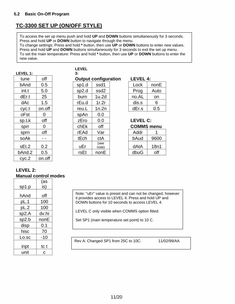
5.2 Basic On-Off Program TC-3300 SET UP (ON/OFF STYLE)
LEVEL 1: LEVEL 3:
tune off Output configuration LEVEL 4: bAnd 0.5 sp1.d ssd1 Lock nonE int.t 5.0 sp2.d ssd2 Prog Auto dEr.t 25 burn 1u.2d no.AL on dAc 1.5 rEu.d 1r.2r dis.s 6 cyc.t on.off reu.L 1n.2n dEr.s 0.5 oFst 0 spAn 0.0 sp.Lk off zEro 0.0 LEVEL C: sprr 0 chEk off COMMS menu sprn off rEAd Var Addr 1 soAk - - tEch ctA bAud 9600
sEt.2 0.2 uEr (see note) dAtA 18n1
bAnd.2 0.5 rsEt nonE dbuG off cyc.2 on.off
LEVEL 2: Manual control modes
sp1.p (as is)
hAnd off
pL.1 100 pL.2 100
sp2.A dv.hi sp2.b nonE disp 0.1 hisc 70
Lo.sc -10
inpt tc t
unit c
Note: "uEr" value is preset and can not be changed, however it provides access to LEVEL 4. Press and hold UP and DOWN buttons for 10 seconds to access LEVEL 4. LEVEL C only visible when COMMS option fitted. Set SP1 (main temperature set point) to 10 C.
To access the set up menu push and hold UP and DOWN buttons simultaneously for 3 seconds. Press and hold UP or DOWN button to navigate through the menu. To change settings: Press and hold * button, then use UP or DOWN buttons to enter new values. Press and hold UP and DOWN buttons simultaneously for 3 seconds to exit the set up menu. To set the main temperature: Press and hold * button, then use UP or DOWN buttons to enter the new value.
Rev A: Changed SP1 from 25C to 10C. 11/02/99/AA
12/20
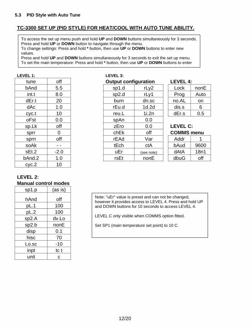
5.3 PID Style with Auto Tune TC-3300 SET UP (PID STYLE) FOR HEAT/COOL WITH AUTO TUNE ABILITY. LEVEL 1: LEVEL 3:
tune off Output configuration LEVEL 4: bAnd 5.5 sp1.d rLy2 Lock nonE int.t 8.0 sp2.d rLy1 Prog Auto dEr.t 20 burn dn.sc no.AL on dAc 1.0 rEu.d 1d.2d dis.s 6 cyc.t 10 reu.L 1i.2n dEr.s 0.5 oFst 0.0 spAn 0.0 sp.Lk off zEro 0.0 LEVEL C: sprr 0 chEk off COMMS menu sprn off rEAd Var Addr 1 soAk - - tEch ctA bAud 9600 sEt.2 -2.0 uEr (see note) dAtA 18n1
bAnd.2 1.0 rsEt nonE dbuG off cyc.2 10
LEVEL 2: Manual control modes
sp1.p (as is)
hAnd off
pL.1 100 pL.2 100
sp2.A dv.Lo sp2.b nonE disp 0.1 hisc 70
Lo.sc -10 inpt tc t unit c
Note: "uEr" value is preset and can not be changed, however it provides access to LEVEL 4. Press and hold UP and DOWN buttons for 10 seconds to access LEVEL 4. LEVEL C only visible when COMMS option fitted. Set SP1 (main temperature set point) to 10 C.
To access the set up menu push and hold UP and DOWN buttons simultaneously for 3 seconds. Press and hold UP or DOWN button to navigate through the menu. To change settings: Press and hold * button, then use UP or DOWN buttons to enter new values. Press and hold UP and DOWN buttons simultaneously for 3 seconds to exit the set up menu. To set the main temperature: Press and hold * button, then use UP or DOWN buttons to enter
13/20
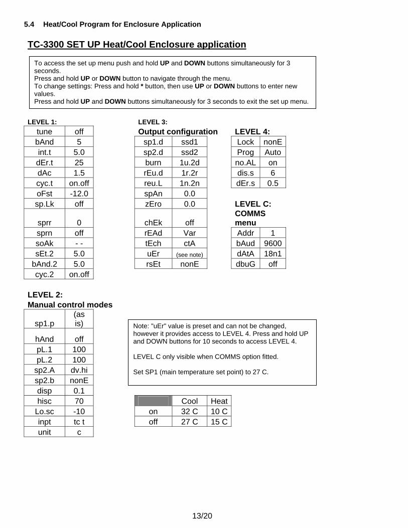
5.4 Heat/Cool Program for Enclosure Application TC-3300 SET UP Heat/Cool Enclosure application LEVEL 1: LEVEL 3:
tune off Output configuration LEVEL 4: bAnd 5 sp1.d ssd1 Lock nonE int.t 5.0 sp2.d ssd2 Prog Auto dEr.t 25 burn 1u.2d no.AL on dAc 1.5 rEu.d 1r.2r dis.s 6 cyc.t on.off reu.L 1n.2n dEr.s 0.5 oFst -12.0 spAn 0.0 sp.Lk off zEro 0.0 LEVEL C:
sprr 0 chEk off COMMS menu
sprn off rEAd Var Addr 1 soAk - - tEch ctA bAud 9600 sEt.2 5.0 uEr (see note) dAtA 18n1
bAnd.2 5.0 rsEt nonE dbuG off cyc.2 on.off
LEVEL 2: Manual control modes
sp1.p (as is)
hAnd off
pL.1 100 pL.2 100
sp2.A dv.hi sp2.b nonE disp 0.1 hisc 70 Cool Heat
Lo.sc -10 on 32 C 10 C inpt tc t off 27 C 15 C unit c
Note: "uEr" value is preset and can not be changed, however it provides access to LEVEL 4. Press and hold UP and DOWN buttons for 10 seconds to access LEVEL 4. LEVEL C only visible when COMMS option fitted. Set SP1 (main temperature set point) to 27 C.
To access the set up menu push and hold UP and DOWN buttons simultaneously for 3 seconds. Press and hold UP or DOWN button to navigate through the menu. To change settings: Press and hold * button, then use UP or DOWN buttons to enter new values. Press and hold UP and DOWN buttons simultaneously for 3 seconds to exit the set up menu.
14/20
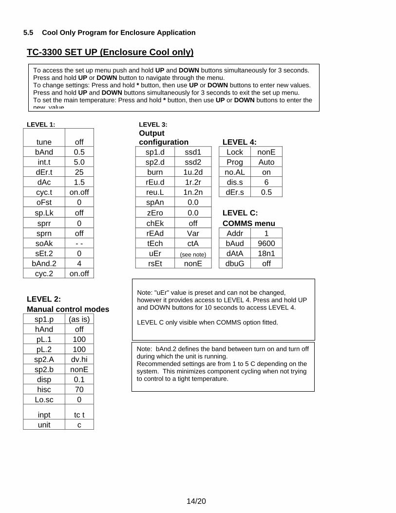
5.5 Cool Only Program for Enclosure Application TC-3300 SET UP (Enclosure Cool only) LEVEL 1: LEVEL 3:
tune off Output configuration LEVEL 4:
bAnd 0.5 sp1.d ssd1 Lock nonE int.t 5.0 sp2.d ssd2 Prog Auto dEr.t 25 burn 1u.2d no.AL on dAc 1.5 rEu.d 1r.2r dis.s 6 cyc.t on.off reu.L 1n.2n dEr.s 0.5 oFst 0 spAn 0.0 sp.Lk off zEro 0.0 LEVEL C: sprr 0 chEk off COMMS menu sprn off rEAd Var Addr 1 soAk - - tEch ctA bAud 9600 sEt.2 0 uEr (see note) dAtA 18n1
bAnd.2 4 rsEt nonE dbuG off cyc.2 on.off
LEVEL 2: Manual control modes
sp1.p (as is) hAnd off pL.1 100 pL.2 100
sp2.A dv.hi sp2.b nonE disp 0.1 hisc 70
Lo.sc 0
inpt tc t
unit c
Note: "uEr" value is preset and can not be changed, however it provides access to LEVEL 4. Press and hold UP and DOWN buttons for 10 seconds to access LEVEL 4. LEVEL C only visible when COMMS option fitted.
To access the set up menu push and hold UP and DOWN buttons simultaneously for 3 seconds. Press and hold UP or DOWN button to navigate through the menu. To change settings: Press and hold * button, then use UP or DOWN buttons to enter new values. Press and hold UP and DOWN buttons simultaneously for 3 seconds to exit the set up menu. To set the main temperature: Press and hold * button, then use UP or DOWN buttons to enter the new value
Note: bAnd.2 defines the band between turn on and turn off during which the unit is running. Recommended settings are from 1 to 5 C depending on the system. This minimizes component cycling when not trying to control to a tight temperature.
15/20
6 EXTERNAL RELAYS (applies only to the models with external relays)
16/20
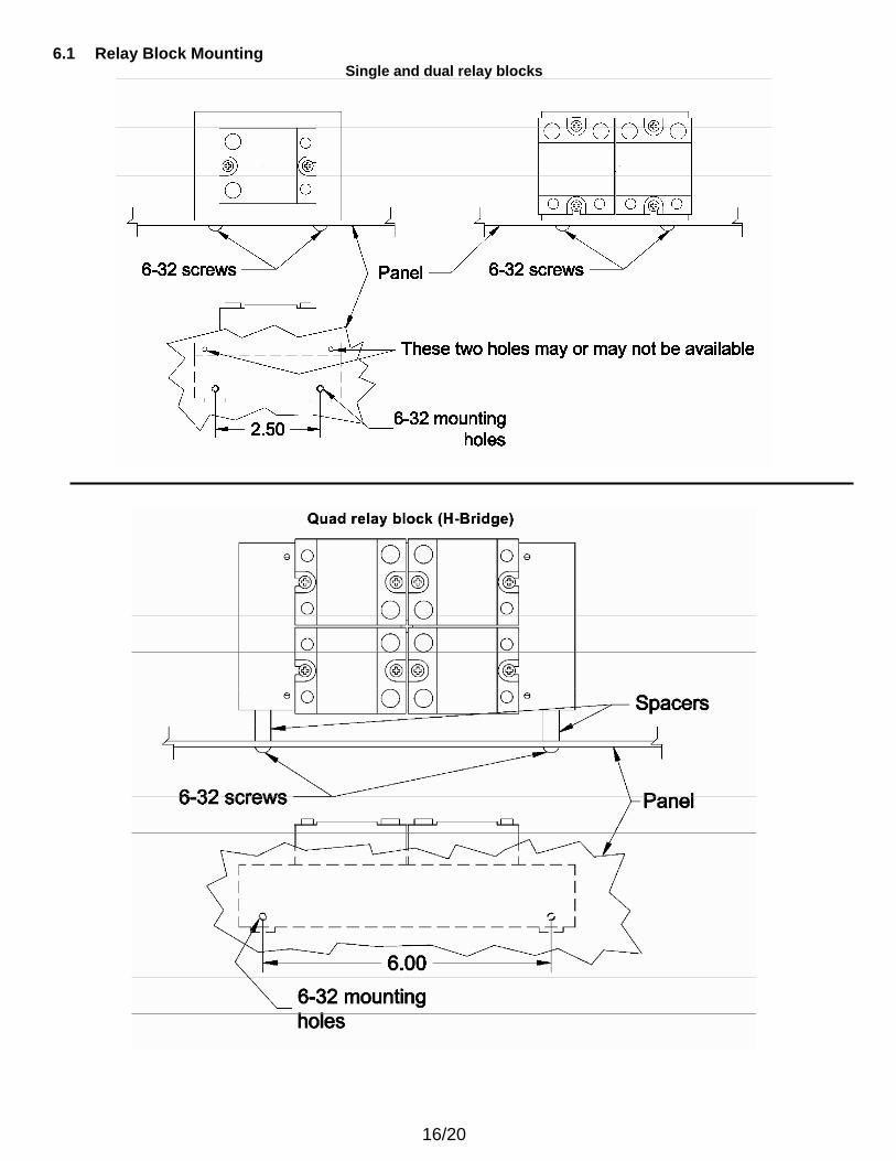
6.1 Relay Block Mounting Single and dual relay blocks
17/20
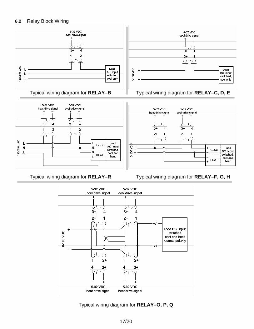
6.2 Relay Block Wiring
Typical wiring diagram for RELAY–B Typical wiring diagram for RELAY–C, D, E
Typical wiring diagram for RELAY–R Typical wiring diagram for RELAY–F, G, H
Typical wiring diagram for RELAY–O, P, Q
18/20
7 RS-232 AND RS-485 COMMUNICATIONS
This section is applicable only to the models with communications option. 7.1 CALCOMMS Software CALCOMMSTM is a graphic WINDOWSTM based software package designed for PC supervision of TC- 3300 controllers. It offers the capability of remote adjustment, instrument configuration, cloning, saving and retrieving instrument settings to files together with logging and charting in real time. Communication uses the MODBUS® protocol via either a fully isolated RS232 or RS485 link depending on the number of instruments and the transmission distances involved in the application. CALCOMMS is available as an option to order reference part number “100-1GB-300”. 7.2 PC Requirements for CALCOMMS To gain the full benefit of CALCOMMS software, it is recommend that the PC is fitted with a Pentium processor and is running WINDOWS 95 or Windows NT programs. A minimum of 16 Mb RAM is recommended to run the program, together with enough free hard disc space to meet logging requirements. 7.3 MODBUS RTU Protocols Reference MODBUS RTU communications guide.
19/20
8 WARRANTY LIMITED WARRANTY In the event a defect in material or workmanship is discovered in any of TECA’s products within one year after the date they are delivered to Buyer, and if: (a) TECA is notified of the defect in writing by certified mail within 14 days of the date of discovery; (b) TECA may then either, at its sole discretion, inspect the product at Buyer’s location, or require that the product be made available at Buyer’s expense at TECA’s premises for TECA’s inspection within 14 days of the date of notification; and (c ) the products are defective and the defects result from faulty materials and/or workmanship and not in any way from accident, misuse, misapplication, mishandling, modification, or alteration by the Buyer or the shipper, then TECA shall, at its sole option, repair or exchange defective products free of charge to Buyer, or credit to buyer the price of the defective products. ALL OTHER WARRANTIES, EXPRESS OR IMPLIED, ARE EXCLUDED, INCLUDING BUT NOT LIMITED TO THE IMPLIED WARRANTIES OF MERCHANTABILITY AND FITNESS FOR A PARTICULAR PURPOSE. IN NO EVENT SHALL TECA BE LIABLE FOR ANY CLAIM BASED UPON BREACH OF EXPRESS OR IMPLIED WARRANTY OR ANY OTHER DAMAGES WHETHER SPECIAL, INDIRECT, INCIDENTAL, CONSEQUENTIAL, LOST PROFITS, BUSINESS INTERRUPTION, OR LOSS OF BUSINESS OR CUSTOMER RELATIONSHIPS. RETURNED GOODS, RESTOCKING CHARGES In order to return merchandise for any reason (repair, replacement, or credit) a return authorization number must be issued by TECA. New merchandise may not be returned for credit beyond 60 days from shipment. Charges for incidental or other damages may also be made. All returned goods must be sent freight prepaid. A restocking charge of 15% will apply. On special equipment and custom modified equipment orders, additional incremental cancellation charges may be made.

20/20


