52
TC-4000 OPERATOR'S MANUAL Issue 1 2/09
TC-4000
OPERATOR'S MANUAL
Issue 12/09
CONTENTS
PAGE
INTRODUCTION 1
SAFETY AND INSTALLATION 2
SÉCURITÉ ET CONSIGNES D'INSTALLATION 5
SICHERHEITS- UND INSTALLATIONSINFORMATIONEN 8
INFORMACIÓN DE SEGURIDAD E INSTALACIÓN 11
INFORMAZIONI SULLA SICUREZZA E L'INSTALLAZIONE 14
BEFORE SWITCHING ON 17
CONTACT INFORMATION 18
TC-4000 SPECIFICATION 19
USER OPERATION AND CONSUMABLES 21Heated lid 21Tubes or reaction vessels 22Switching on 22
FRONT PANEL CONTROLS 23The LCD display 23Indicators 23The keys 24
PROGRAMMING THE TC-4000 25Programming Options 26Option 1: Creating programs using templates 26Option 2: Creating a new program 30Example programs 31Programming 31To program increment or decrement temperature or time. 34To run a program 38
INFORMATION 40
CONFIGURATION 40
RUNNING THE TC-4000 FROM A PC 43Connecting one unit to the computer using an RS232 cable 43Connecting several units to the computer using the daisy chain cables 44
USER MAINTENANCE 45Cleaning your TC-4000 45Block removal 46
FREQUENTLY ASKED QUESTIONS 46
ADDITIONAL INFORMATION 47Fault Finding 47Fuses 47The heated lid over-temperature cut-out 48Insulation testing 48
INTERCHANGEABLE BLOCKS 48
ACCESSORIES 49
REPLACEMENT PARTS 49
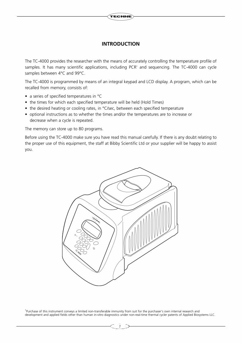
INTRODUCTION
The TC-4000 provides the researcher with the means of accurately controlling the temperature profile ofsamples. It has many scientific applications, including PCR1 and sequencing. The TC-4000 can cyclesamples between 4°C and 99°C.
The TC-4000 is programmed by means of an integral keypad and LCD display. A program, which can berecalled from memory, consists of:
• a series of specified temperatures in °C• the times for which each specified temperature will be held (Hold Times)• the desired heating or cooling rates, in °C/sec, between each specified temperature • optional instructions as to whether the times and/or the temperatures are to increase or
decrease when a cycle is repeated.
The memory can store up to 80 programs.
Before using the TC-4000 make sure you have read this manual carefully. If there is any doubt relating tothe proper use of this equipment, the staff at Bibby Scientific Ltd or your supplier will be happy to assistyou.
1
1Purchase of this instrument conveys a limited non-transferable immunity from suit for the purchaser's own internal research anddevelopment and applied fields other than human in-vitro diagnostics under non-real-time thermal cycler patents of Applied Biosystems LLC.
TC-4000
SAFETY AND INSTALLATION
OPERATOR SAFETY
Please read this manual carefully before using the thermal cycler. If the equipment is not used in themanner described in this manual the protection provided by the equipment might be impaired.
All Bibby Scientific Ltd instruments are designed to conform to international safety requirements and arefitted with an over-temperature cut-out. If a safety problem should be encountered then switch off theunit at the mains socket and remove the plug from the electricity supply.
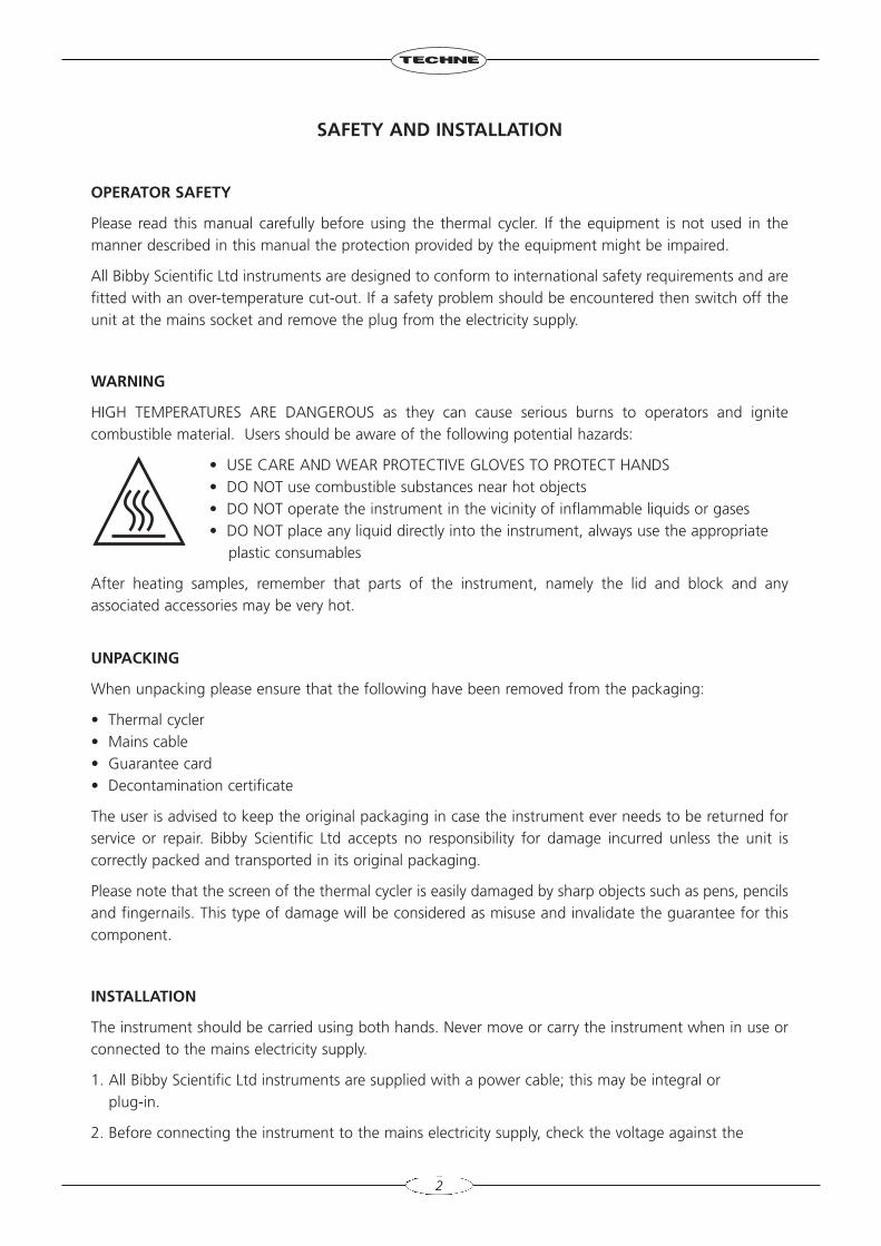
WARNING
HIGH TEMPERATURES ARE DANGEROUS as they can cause serious burns to operators and ignitecombustible material. Users should be aware of the following potential hazards:
• USE CARE AND WEAR PROTECTIVE GLOVES TO PROTECT HANDS• DO NOT use combustible substances near hot objects• DO NOT operate the instrument in the vicinity of inflammable liquids or gases• DO NOT place any liquid directly into the instrument, always use the appropriate
plastic consumables
After heating samples, remember that parts of the instrument, namely the lid and block and anyassociated accessories may be very hot.
UNPACKING
When unpacking please ensure that the following have been removed from the packaging:
• Thermal cycler• Mains cable• Guarantee card• Decontamination certificate
The user is advised to keep the original packaging in case the instrument ever needs to be returned forservice or repair. Bibby Scientific Ltd accepts no responsibility for damage incurred unless the unit iscorrectly packed and transported in its original packaging.
Please note that the screen of the thermal cycler is easily damaged by sharp objects such as pens, pencilsand fingernails. This type of damage will be considered as misuse and invalidate the guarantee for thiscomponent.
INSTALLATION
The instrument should be carried using both hands. Never move or carry the instrument when in use orconnected to the mains electricity supply.
1. All Bibby Scientific Ltd instruments are supplied with a power cable; this may be integral or plug-in.
2. Before connecting the instrument to the mains electricity supply, check the voltage against the
2
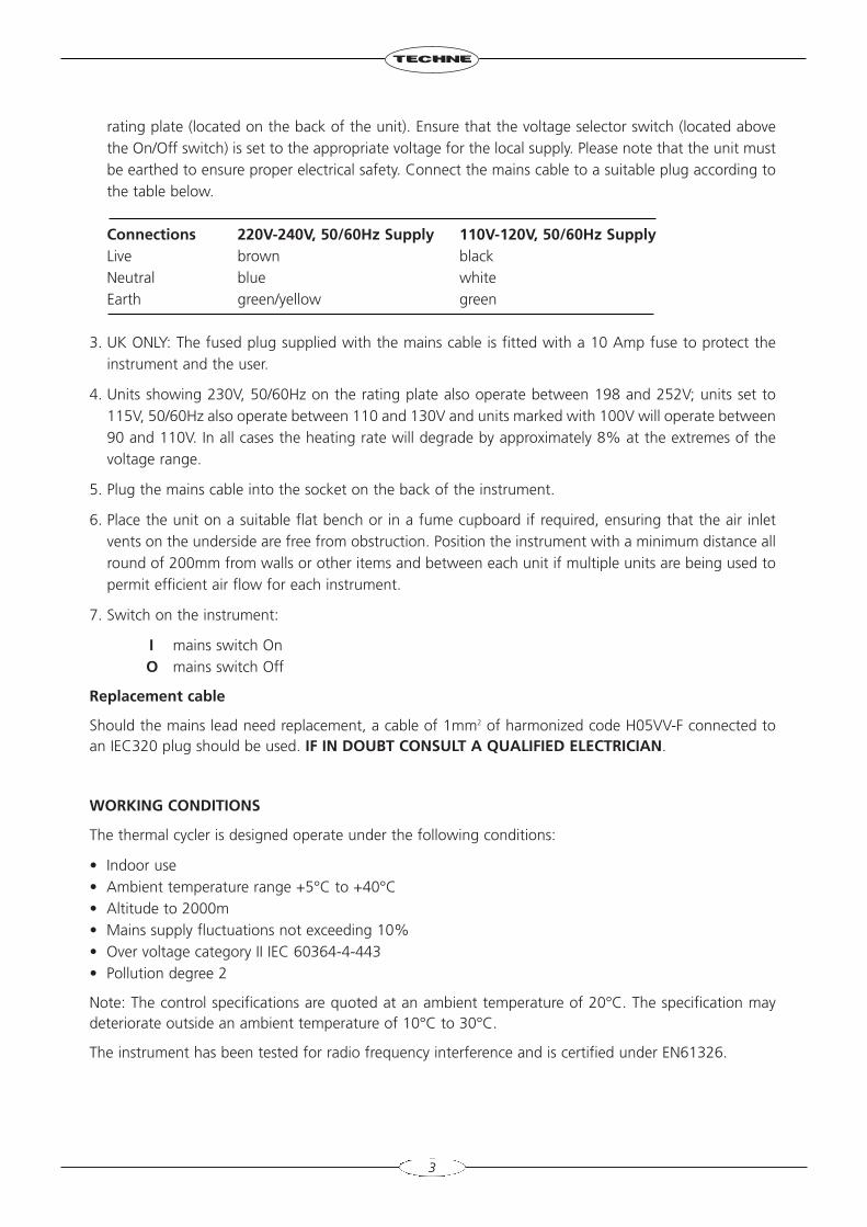
rating plate (located on the back of the unit). Ensure that the voltage selector switch (located abovethe On/Off switch) is set to the appropriate voltage for the local supply. Please note that the unit mustbe earthed to ensure proper electrical safety. Connect the mains cable to a suitable plug according tothe table below.
Connections 220V-240V, 50/60Hz Supply 110V-120V, 50/60Hz SupplyLive brown blackNeutral blue whiteEarth green/yellow green
3. UK ONLY: The fused plug supplied with the mains cable is fitted with a 10 Amp fuse to protect theinstrument and the user.
4. Units showing 230V, 50/60Hz on the rating plate also operate between 198 and 252V; units set to115V, 50/60Hz also operate between 110 and 130V and units marked with 100V will operate between90 and 110V. In all cases the heating rate will degrade by approximately 8% at the extremes of thevoltage range.
5. Plug the mains cable into the socket on the back of the instrument.
6. Place the unit on a suitable flat bench or in a fume cupboard if required, ensuring that the air inletvents on the underside are free from obstruction. Position the instrument with a minimum distance allround of 200mm from walls or other items and between each unit if multiple units are being used topermit efficient air flow for each instrument.
7. Switch on the instrument:
I mains switch OnO mains switch Off
Replacement cable
Should the mains lead need replacement, a cable of 1mm2 of harmonized code H05VV-F connected toan IEC320 plug should be used. IF IN DOUBT CONSULT A QUALIFIED ELECTRICIAN.
WORKING CONDITIONS
The thermal cycler is designed operate under the following conditions:
• Indoor use• Ambient temperature range +5°C to +40°C• Altitude to 2000m• Mains supply fluctuations not exceeding 10%• Over voltage category II IEC 60364-4-443• Pollution degree 2
Note: The control specifications are quoted at an ambient temperature of 20°C. The specification maydeteriorate outside an ambient temperature of 10°C to 30°C.
The instrument has been tested for radio frequency interference and is certified under EN61326.
3
4
GUARANTEE
The instrument is guaranteed against any defect in material or workmanship for the period specified onthe enclosed guarantee card. This period is effective from the date of purchase; within this period alldefective parts will be replaced free of charge provided that the defect is not the result of an accident,misuse or negligence. The screen of the thermal cycler can be damaged by sharp objects such as pens,pencils and fingernails. Damage of this sort will be considered misuse and will invalidate the guaranteefor this component.
Servicing under this guarantee should be obtained from the supplier of the instrument.
This manual has been prepared for the convenience of Techne's customers and nothing in this manualshall be taken as a warranty, condition or representation concerning the description, merchantability,fitness for purpose or otherwise of the unit or components.
Notwithstanding the description and specification(s) of the instruments contained in the operator'smanual, Techne reserves the right to make such changes as it sees fit to the instruments or to any of thecomponents.
SÉCURITÉ ET CONSIGNES D'INSTALLATION
SÉCURITÉ DE L’OPÉRATEUR
Lire attentivement le présent manuel avant d'utiliser le cycleur thermique. Si ce matériel n'est pas utiliséde la manière décrite dans le présent manuel, la protection fournie risque d'être compromise.
Tous les appareils Bibby Scientific Ltd sont conçus pour être conformes aux exigences internationales desécurité et sont dotés d'une coupure en cas de surchauffe. Si un problème de sécurité survient, mettrel'appareil hors tension au niveau de la prise secteur et débrancher la fiche de l'alimentation électrique.
AVERTISSEMENT
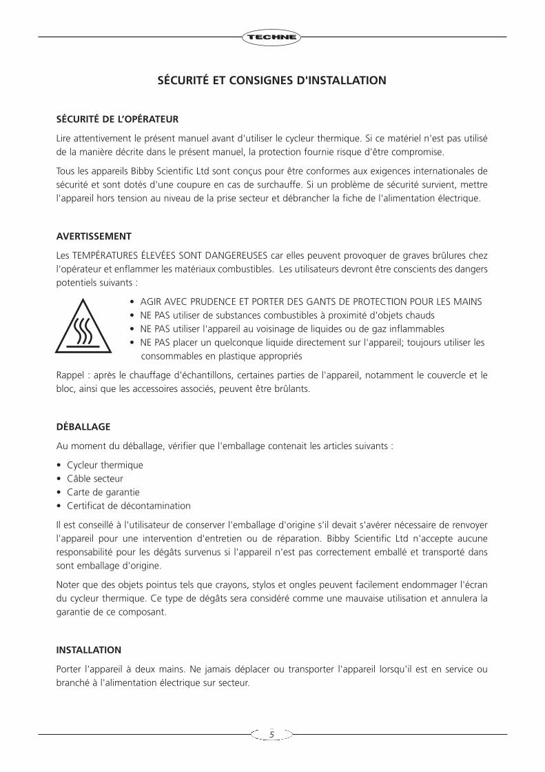
Les TEMPÉRATURES ÉLEVÉES SONT DANGEREUSES car elles peuvent provoquer de graves brûlures chezl'opérateur et enflammer les matériaux combustibles. Les utilisateurs devront être conscients des dangerspotentiels suivants :
• AGIR AVEC PRUDENCE ET PORTER DES GANTS DE PROTECTION POUR LES MAINS• NE PAS utiliser de substances combustibles à proximité d'objets chauds• NE PAS utiliser l'appareil au voisinage de liquides ou de gaz inflammables• NE PAS placer un quelconque liquide directement sur l'appareil; toujours utiliser les
consommables en plastique appropriés
Rappel : après le chauffage d'échantillons, certaines parties de l'appareil, notamment le couvercle et lebloc, ainsi que les accessoires associés, peuvent être brûlants.
DÉBALLAGE
Au moment du déballage, vérifier que l'emballage contenait les articles suivants :
• Cycleur thermique• Câble secteur• Carte de garantie• Certificat de décontamination
Il est conseillé à l'utilisateur de conserver l'emballage d'origine s'il devait s'avérer nécessaire de renvoyerl'appareil pour une intervention d'entretien ou de réparation. Bibby Scientific Ltd n'accepte aucuneresponsabilité pour les dégâts survenus si l'appareil n'est pas correctement emballé et transporté danssont emballage d'origine.
Noter que des objets pointus tels que crayons, stylos et ongles peuvent facilement endommager l'écrandu cycleur thermique. Ce type de dégâts sera considéré comme une mauvaise utilisation et annulera lagarantie de ce composant.
INSTALLATION
Porter l'appareil à deux mains. Ne jamais déplacer ou transporter l'appareil lorsqu'il est en service oubranché à l'alimentation électrique sur secteur.
5
1. Tous les appareils Bibby Scientific Ltd sont livrés avec un câble d'alimentation, qui peut être intégré àl'appareil ou muni d'une fiche.
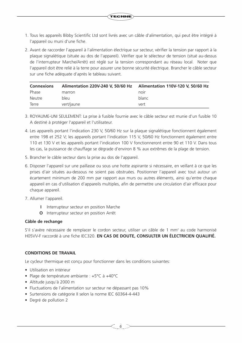
2. Avant de raccorder l'appareil à l'alimentation électrique sur secteur, vérifier la tension par rapport à laplaque signalétique (située au dos de l'appareil). Vérifier que le sélecteur de tension (situé au-dessusde l'interrupteur Marche/Arrêt) est réglé sur la tension correspondant au réseau local. Noter quel'appareil doit être relié à la terre pour assurer une bonne sécurité électrique. Brancher le câble secteursur une fiche adéquate d'après le tableau suivant.
Connexions Alimentation 220V-240 V, 50/60 Hz Alimentation 110V-120 V, 50/60 HzPhase marron noirNeutre bleu blancTerre vert/jaune vert
3. ROYAUME-UNI SEULEMENT: La prise à fusible fournie avec le câble secteur est munie d'un fusible 10A destiné à protéger l'appareil et l'utilisateur.
4. Les appareils portant l'indication 230 V, 50/60 Hz sur la plaque signalétique fonctionnent égalemententre 198 et 252 V; les appareils portant l'indication 115 V, 50/60 Hz fonctionnent également entre110 et 130 V et les appareils portant l'indication 100 V fonctionneront entre 90 et 110 V. Dans tousles cas, la puissance de chauffage se dégrade d'environ 8 % aux extrêmes de la plage de tension.
5. Brancher le câble secteur dans la prise au dos de l'appareil.
6. Disposer l'appareil sur une paillasse ou sous une hotte aspirante si nécessaire, en veillant à ce que lesprises d'air situées au-dessous ne soient pas obstruées. Positionner l'appareil avec tout autour unécartement minimum de 200 mm par rapport aux murs ou autres éléments, ainsi qu'entre chaqueappareil en cas d'utilisation d'appareils multiples, afin de permettre une circulation d'air efficace pourchaque appareil.
7. Allumer l'appareil.
I Interrupteur secteur en position MarcheO Interrupteur secteur en position Arrêt
Câble de rechange
S'il s'avère nécessaire de remplacer le cordon secteur, utiliser un câble de 1 mm2 au code harmoniséH05VV-F raccordé à une fiche IEC320. EN CAS DE DOUTE, CONSULTER UN ÉLECTRICIEN QUALIFIÉ.
CONDITIONS DE TRAVAIL
Le cycleur thermique est conçu pour fonctionner dans les conditions suivantes:
• Utilisation en intérieur• Plage de température ambiante : +5°C à +40°C• Altitude jusqu'à 2000 m• Fluctuations de l'alimentation sur secteur ne dépassant pas 10%• Surtensions de catégorie II selon la norme IEC 60364-4-443• Degré de pollution 2
6
Remarque: Les caractéristiques de régulation sont indiquées à une température ambiante de 20°C. Cescaractéristiques peuvent se détériorer en dehors d'une température ambiante de 10°C à 30°C.
L'appareil a été testé en matière de perturbations radioélectriques et est certifié selon la norme EN61326.
GARANTIE
L'appareil est garanti contre tout défaut de matériaux ou vice de fabrication pendant la période préciséesur la carte de garantie jointe. Cette période s'applique à compter de la date d'achat; pendant cettepériode, toutes les pièces défectueuses seront remplacées gratuitement à condition que le défaut ne soitpas le résultat d'un accident, d'une mauvaise utilisation ou d'une négligence. Des objets pointus tels quecrayons, stylos et ongles peuvent endommager l'écran du cycleur thermique. Les dégâts de cette sorteseront considérés comme une mauvaise utilisation et annuleront la garantie de ce composant.
Dans le cadre de cette garantie, le service après-vente est à obtenir auprès du fournisseur de l'appareil.
Le présent manuel a été préparé pour le confort des clients de Techne et rien dans son contenu ne doitêtre pris comme une garantie, une condition ou une affirmation concernant la description, la qualitémarchande, l'adéquation à un usage particulier ou autre de l'appareil ou de ses composants.
Nonobstant la description et les caractéristiques techniques des appareils figurant dans le manuel del'utilisateur, Techne se réserve le droit d'apporter aux appareils ou à n'importe quel composant leschangements jugés utiles.
7
SICHERHEITS - UND INSTALLATIONSINFORMATIONEN
SICHERHEIT DES BEDIENPERSONALS
Lesen Sie diese Anleitung vor Verwendung des Thermocyclers bitte sorgfältig durch. Wenn das Gerätnicht entsprechend der Bedienungsanleitung eingesetzt wird, können die Schutzfunktionen des Gerätesbeeinträchtigt werden.
Alle Geräte von Bibby Scientific Ltd entsprechen den internationalen Sicherheitsanforderungen und sindmit einer Übertemperatur-Schutzvorrichtung ausgestattet. Bei einer Sicherheitsstörung bitte das Gerät ander Steckdose ausschalten und den Netzstecker ziehen.
ACHTUNG
HOHE TEMPERATUREN STELLEN EINE GEFAHRENQUELLE DAR. Sie können schwere Brandverletzungverursachen und brennbare Stoffe entzünden. Der Benutzer sollt sich mit den möglichen Gefahrenvertraut machen:
• UMSICHTIG VORGEHEN UND SCHUTZHANDSCHUHE TRAGEN• KEINE brennbaren Stoffe in der Nähe heißer Gegenstände verwenden• Das Gerät NICHT in der Nähe entzündlicher Flüssigkeiten oder Gase betreiben• Flüssigkeiten NICHT direkt auf das Gerät auftragen - verwenden Sie stets die
entsprechenden Kunststoffeinsätze
Nach der Erhitzung von Proben daran denken, dass bestimmte Geräteteile wie Deckel, Thermoblock undZubehörteile sehr heiß sein können.
AUSPACKEN
Beim Auspacken darauf achten, dass der folgende Lieferumfang vorhanden ist:
• Thermocycler• Netzkabel• Garantiekarte• Dekontaminationszertifikat
Wir empfehlen die Originalverpackung aufzubewahren, falls das Gerät zwecks Wartung oder Reparaturzurückgeschickt werden muss. Bibby Scientific Ltd übernimmt keine Verantwortung fürTransportschäden, wenn das Gerät nicht ordnungsgemäß verpackt in der Originalpackung verschicktwird.
Achten Sie bitte darauf, dass die Anzeige des Thermocyclers durch spitze bzw. scharfe Gegenstände wieStifte, Bleistifte und Fingernägel leicht zerkratzt wird. Diese Art von Beschädigung gilt als Missbrauch desGeräts und führt zur Ungültigkeit der Garantie für dieses Gerät.
INBETRIEBNAHME
Das Gerät mit beiden Händen tragen. Das Gerät unter keinen Umständen transportieren, wenn es inBetrieb ist, oder während das Gerät noch am Netz angeschlossen ist.
8
1. Alle Geräte von Bibby Scientific Ltd werden mit einem Netzkabel geliefert, das entweder eingestecktwird oder fest mit dem Gerät verbunden ist.
2. Vor dem Anschluss bitte kontrollieren, ob die Stromversorgung den Angaben auf dem Typenschild (aufder Geräterückseite) entspricht. Darauf achten, dass der Spannungswähler (über dem Ein/Aus-Schalter)auf die entsprechende örtliche Spannung eingestellt ist. Um die elektrische Sicherheit zugewährleisten, muss dieses Gerät geerdet werden. Schließen Sie das Netzkabel entsprechend derfolgenden Tabelle an einen geeigneten Stecker an.
Anschluss 220/240V, 50/60Hz 110V/120V, 50/60HzPhase Braun SchwarzNeutral Blau WeißErde Grün/Gelb Grün
3. NUR FÜR GROSSBRITANNIEN: der mit dem Netzkabel gelieferte Sicherungsstecker enthält eine 10Amp. Sicherung zum Schutz des Geräts und des Anwenders.
4. Geräte mit der Bezeichnung 230V, 50/60Hz auf dem Typenschild können mit Spannungen zwischen198 und 252V betrieben werden; Geräte für 115V, 50/60Hz können mit Spannungen zwischen 110und 130V betrieben werden. Bei Geräten für 100V gilt der Bereich 90 bis 110V. In allen Fällen reduziertsich die Erhitzungsrate um etwa 8% in den äußeren Spannungsbereichen.
5. Stecken Sie das Netzkabel in die Buchse auf der Geräterückseite ein.
6. Stellen Sie das Gerät auf einen geeigneten ebenen Tisch oder in einem Abzugsschrank auf und sorgenSie dafür, dass die Lufteinlassschlitze auf der Geräteunterseite nicht blockiert sind. Das Gerät musseinen Mindestabstand von 200 mm zu Wänden und anderen Gegenständen bzw. zu anderen Gerätendieser Art aufweisen, um einen ausreichenden Luftstrom zu gewährleisten.
7. Schalten Sie das Gerät ein:
I Netzschalter Ein
O Netzschalter Aus
Ersatzkabel
Bei einem eventuellen Austausch des Netzkabels wird ein Kabel vom Typ H05VV-F mit 1 mm2
Adernquerschnitt und Europastecker (IEC 320) benötigt. IM ZWEIFELSFALL EINEN ELEKTRO-FACHMANN HINZUZIEHEN.
EINSATZBEDINGUNGEN
Der Thermocycler ist für den Einsatz unter folgenden Bedingungen ausgelegt:
• Gebrauch in Innenräumen• Umgebungstemperatur zwischen +5°C to +40°C• Höhe: bis zu 2000 m• Relative Feuchte nicht über 95%• Netzspannungsschwankungen nicht über 10%• Überspannungsklasse 2 IEC 60364-4-443• Verschmutzungsgrad 2
9
Hinweis: Die Gerätespezifikationen beziehen sich auf eine Umgebungstemperatur von 20°C und könnensich außerhalb des Bereichs 10°C bis 30°C verschlechtern.
Das Gerät wurde auf HF-Störeinflüsse geprüft und entspricht den EMV-Bedingungen nach EN61326.
GARANTIE
Bibby Scientific Ltd gewährleistet, dass dieses Gerät für den auf der Garantiekarte angegebenen Zeitraumkeine Herstellungs- und Materialmängel aufweist. Dieser Zeitraum tritt ab dem Verkaufsdatum in Kraft.Innerhalb dieses Zeitraums werden alle defekten Teile kostenlos ausgetauscht, soweit der Defekt nicht aufeinen Unfall, Missbrauch oder Nachlässigkeit zurückzuführen ist. Die Anzeige des Thermocylers kan durchspitze/scharfe Gegenstände wie Stifte, Bleistifte und Fingernägel beschädigt werden. Diese Art vonBeschädigung gilt als Missbrauch des Geräts und führt zur Ungültigkeit der Garantie für dieses Gerät.
Wartungsarbeiten, die unter diese Garantie fallen, müssen von der Verkaufsstelle für dieses Gerätgehandhabt werden.
Diese Anleitung wurde zur Information der Kunden von Techne erstellt und stellt in keinster Weise eineGewährleistung, Bedingung oder Darstellung bezüglich der Beschreibung, Marktgängigkeit oderZweckdienlichkeit dieser Geräte oder Bauteile dar.
Unabhängig von Beschreibung und Spezifikation(en) des hier beschriebenen Geräts behält sich Technedas Recht vor, Änderungen an diesem Gerät oder dessen Bauteilen vorzunehmen.
10
INFORMACIÓN DE SEGURIDAD E INSTALACIÓN
SEGURIDAD DEL OPERARIO
Lea atentamente este manual antes de utilizar el ciclador térmico. Si el equipo no se utiliza de la formadescrita en este manual, se reducirá la protección ofrecida por el equipo.
Todos los instrumentos Bibby Scientific Ltd están diseñados para cumplir los requisitos internacionales deseguridad, e incluyen un dispositivo de corte de sobretemperatura. Si se produce un problema deseguridad, apague la unidad en la toma de alimentación y retire el enchufe del suministro eléctrico.
ADVERTENCIA
LAS ALTAS TEMPERATURAS SON PELIGROSAS, ya que pueden ocasionar quemaduras graves a losoperarios y prender el material combustible. Los usuarios deben conocer los posibles riesgos:
• TENGA CUIDADO Y LLEVE GUANTES DE PROTECCIÓN PARA PROTEGERSE LAS MANOS
• NO utilice sustancias combustibles cerca de objetos calientes• NO utilice el instrumento cerca de líquidos o gases inflamables• NO coloque un líquido directamente en el instrumento. Utilice siempre los
consumibles plásticos adecuados
Después de calentar las muestras, recuerde que hay componentes del instrumento que pueden calentarsemucho, concretamente la tapa y el cuerpo y todos los accesorios asociados.
DESEMBALAJE
Durante el desembalaje, asegúrese de sacar los siguientes componentes del embalaje:
• Ciclador térmico• Cable de alimentación• Tarjeta de garantía• Certificado de descontaminación
Se recomienda guardar el embalaje original en caso de que tenga que enviar el instrumento para untrabajo de mantenimiento o reparación. Bibby Scientific Ltd no se responsabiliza de los daños producidossi la unidad no está debidamente embalada y no se envía en su embalaje original.
Tenga en cuenta que los objetos punzantes, p.ej.: bolígrafos, lápices y uñas, pueden dañar fácilmente lapantalla del ciclador térmico. Este tipo de daño se considerará como un uso incorrecto, e invalidará lagarantía de este componente.
INSTALACIÓN
El instrumento se debe transportar con las dos manos. No mueva ni lleve el instrumento cuando se utiliceo esté conectado al suministro eléctrico principal.
1. Todos los instrumentos Bibby Scientific Ltd se suministran con un cable de alimentación, que puede serintegrado o 'enchufable'.
11
2. Antes de conectar el instrumento al suministro eléctrico, compruebe que el voltaje coincida con elindicado en la placa de régimen (situada en la parte trasera de la unidad). Asegúrese de que elinterruptor de selección de voltaje (situado encima del interruptor de encendido/apagado) estáajustado al voltaje correcto del suministro eléctrico. El instrumento debe disponer de una toma detierra para garantizar la seguridad eléctrica adecuada. Conecte el cable de alimentación a un enchufeadecuado según la siguiente tabla.
Conexión 220/240V, 50/60Hz Supply 110V/120V Supply, 50/60HzCon corriente marrón negroNeutro azul blancoToma de tierra verde/amarillo verde
3. SÓLO PARA EL REINO UNIDO: El enchufe suministrado con el cable de alimentación incluye un fusiblede 10 amperios para ofrecer protección al instrumento y al usuario.
4. Las unidades cuya placa de régimen indique 230V, 50/60Hz también pueden funcionar entre 198 y252V; las unidades con 115V, 50/60Hz también funcionan entre 110 y 130V, y las unidades con 100Vfuncionan entre 90 y 110V. En todos los casos, el porcentaje de calentamiento disminuirá un 8%aproximadamente en los dos extremos del intervalo de voltaje.
5. Conecte el cable de alimentación en el enchufe situado en la parte trasera del instrumento.
6. Sitúe la unidad sobre una mesa plana o en una campana de laboratorio si es necesario, y asegúrese deque los orificios de ventilación situados en la parte inferior no tienen ninguna obstrucción. Coloque elinstrumento a una distancia mínima de 200 mm alrededor de paredes u otros elementos, y entre cadaunidad (en caso de que se utilicen varias) para que haya una circulación de aire adecuada para cadainstrumento.
7. Encienda el instrumento:
I Interruptor de alimentación encendidoO Interruptor de alimentación apagado
Cable de repuesto
Si es necesario sustituir el cable de alimentación, se debe utilizar un cable de 1mm2 de código armonizadoH05VV, conectado a un enchufe IEC320. EN CASO DE DUDA, PÓNGASE EN CONTACTO CON UNELECTRICISTA.
CONDICIONES DE TRABAJO
El ciclador térmico está diseñado para utilizarse en las condiciones siguientes:
• Uso en interior• Intervalo de temperatura ambiente +5°C a +40°C• Humedad relativa no superior al 95%• Fluctuaciones del suministro eléctrico no superiores al 10%• Categoría de sobrevoltaje II IEC 60364-4-443• Nivel de contaminación 2
Nota: Las especificaciones de control corresponden a una temperatura ambiental de 20ºC. Las
12
especificaciones pueden empeorar si se utiliza el instrumento fuera del intervalo de temperaturacomprendido entre 10°C y 30°C.
Se han realizado pruebas para comprobar la interferencia de radiofrecuencia del instrumento, el cualcumple la normativa EN61326.
GARANTÍA
El instrumento está garantizado contra cualquier defecto en el material o la fabricación durante elperíodo especificado en la tarjeta de garantía que se adjunta. Este período entra en vigor a partir de lafecha de compra. Durante este período, se reemplazarán sin cargo alguno todas las piezas defectuosas,a condición que el defecto sea resultado de un accidente, uso incorrecto o negligencia. Tenga en cuentaque los objetos punzantes, p.ej.: bolígrafos, lápices y uñas, pueden dañar fácilmente la pantalla delciclador térmico. Este tipo de daño se considerará como un uso incorrecto, e invalidará la garantía de estecomponente.
El distribuidor del instrumento proporcionará información sobre las reparaciones realizadas bajo estagarantía.
Este manual se ha preparado con una finalidad informativa para los clientes de Techne, y ninguna partedel manual se deberá considerar como una garantía, condición o reflejo con respecto a la descripción,comerciabilidad, idoneidad para un fin determinado o de otro tipo de la unidad o sus componentes.
Con independencia de la descripción y las especificaciones del instrumento que se indican en el manualdel operario, Techne se reserva el derecho de realizar cambios en el instrumento o en cualquiera de suscomponentes cuando lo estime oportuno.
13
INFORMAZIONI SULLA SICUREZZA E L'INSTALLAZIONE
SICUREZZA DELL'OPERATORE
Leggere attentamente il presente manuale prima di usare il ciclatore termico. Se non si usal'apparecchiatura nel modo descritto nel presente manuale, la protezione fornita dall'unità potrebberisultarne diminuita.
Tutti gli strumenti Bibby Scientific Ltd sono progettati per rispettare i requisiti di sicurezza internazionali esono montati con un sezionatore di sovratemperatura. In caso di problemi di sicurezza, spegnere l'unitàdalla presa di rete centrale e togliere la spina dall'alimentazione elettrica.
AVVERTENZA
Le ALTE TEMPERATURE SONO PERICOLOSE in quanto possono provocare serie ustioni agli operatori edare fuoco al materiale combustibile. Gli utenti devono conoscere i seguenti pericoli potenziali:
• PRESTARE ATTENZIONE ED INDOSSARE GUANTI PROTETTIVI PER LE MANI• NON usare sostanze combustibili vicino ad oggetti caldi• NON mettere in funzione lo strumento nei pressi di liquidi o gas infiammabili• NON collocare alcun tipo di liquido direttamente nello strumento, usare sempre le
parti di consumo in plastica idonee
Dopo aver riscaldato i campioni, ricordare che le parti dello strumento, cioè il coperchio ed il blocco edeventuali accessori associati potrebbero essere molto caldi.
DISIMBALLAGGIO
Durante il disimballaggio, assicurarsi di aver tolto quanto segue dall'imballo:
• Ciclatore termico• Cavo di alimentazione di rete• Scheda di garanzia• Certificato di decontaminazione
Si consiglia all'utente di conservare l'imballaggio originale nel caso in cui occorresse restituire lostrumento per assistenza o riparazioni. Se l'unità non è correttamente imballata e trasportata nel suoimballo originale, Bibby Scientific Ltd non accetta alcuna responsabilità per eventuali danni che dovesseroverificarsi.
Notare come lo schermo del ciclatore termico si danneggia facilmente con oggetti appuntiti come penne,matite ed unghia. Questo tipo di danni sarà considerato come uso improprio e renderà nulla la garanziaper questo componente.
INSTALLAZIONE
Occorre trasportare lo strumento usando entrambe le mani. Non spostare né trasportare lo strumentoquando è in funzione o collegato all'alimentazione elettrica di rete.
1. Tutti gli strumenti Bibby Scientific Ltd sono forniti con un cavo di alimentazione; può essere integraleo plugin.
14
2. Prima di collegare lo strumento all'alimentazione elettrica di rete, controllare la tensioneconfrontandola con la targhetta riportante i valori nominali (si trova sul retro dell'unità). Assicurarsi cheil selettore di tensione (posto sopra l'interruttore On/Off) sia impostato sulla tensione corretta perl'alimentazione locale. Notare che al fine di garantire la corretta sicurezza elettrica, occorre che l'unitàsia messa a terra. Collegare il cavo di rete ad una presa idonea secondo la tabella riportata alla paginasuccessiva.
Connessione 220/240V, Alimentazione 50/60Hz Alimentazione 110V/120V, 50/60HzSotto tensione marrone neroNeutro blu biancoTerra verde/giallo verde
3. SOLO REGNO UNITO: la spina con fusibile fornita con il cavo di rete è dotata di un fusibile da 10 Ampper proteggere lo strumento e l'utente.
4. Le unità la cui targhetta dei valori nominali indica 230V, 50/60Hz funzionano anche tra 198 e 252V;quelle con 115V, 50/60Hz funzionano anche tra 110 e 130V e quelle contrassegnate da 100Vfunzionano tra 90 e 110V. In tutti i casi, il tasso di riscaldamento diminuirà di circa l'8% agli estremidell'intervallo di tensione.
5. Inserire il cavo di rete nella presa che si trova sul retro dello strumento.
6. Collocare l'unità su un banco piatto idoneo o in una cappa aspirante se necesario, assicurandosi chegli sfiati delle prese d'aria nella parte inferiore non siano ostruiti. Posizionare lo strumento con unadistanza minima attorno di 200 mm. dalle pareti o da altri oggetti e tra ciascuna unità, nel caso in cuisi usino unità multiple, in modo da consentire un flusso di'aria efficace per ciascuno strumento.
7. Accendere lo strumento:
I Interruttore di rete AccesoO Interruttore di rete Spento
Cavo di ricambio
Qualora occorra sostituire il cavo di rete, si dovrà utilizzare un cavo di 1mm2 codice armonizzato H05VV-F collegato ad una spina IEC 320. IN CASO DI DUBBIO, RIVOLGERSI A UN ELETTRICISTAQUALIFICATO.
CONDIZIONI DI ESERCIZIO
Il ciclatore termico è stato progettato per funzionare nelle seguenti condizioni:
• uso interno• range di temperatura ambiente da +5°C a +40°C• altitudine massima 2000 m.• umidità relativa non superiore all'95%• oscillazione dell'alimentazione di rete non superiore al 10%• categoria di sovratensione II IEC 60364-4-443• grado di inquinamento 2
Nota: le specifiche di controllo sono indicate ad una temperatura ambiente di 20°C. Le specifichepotrebbero peggiorare fuori da una temperatura ambiente compresa tra 10°C e 30°C.
15
Lo strumento è stato collaudato per interferenze da radiofrequenze ed è certificato secondo la normaEN61326.
GARANZIA
Lo strumento è garantito da qualsiasi difetto nei materiali o nella lavorazione per il periodo specificatonella scheda di garanzia allegata. Questo periodo è valido dalla data di acquisto; entro tale periodo, tuttele parti difettose saranno sostituite gratuitamente, a condizione che il difetto non sia la conseguenza diun incidente, un uso improprio o negligenza. Lo schermo del ciclatore termico può essere danneggiatoda oggetti appuntiti come penne, matite ed unghia. Tale tipo di danno sarà considerato uso improprio erenderà nulla la garanzia per questo componente.
L'assistenza secondo quanto stabilito dalla presente garanzia deve essere ottenuta dal fornitore dellostrumento.
Il presente manuale è stato preparato ad uso dei clienti di Techne niente di quanto in esso contenutocostituisce garanzia, condizione o rappresentanza riguardo la descrizione, la commerciabilità, l'idoneitàallo scopo o altrimenti dell'unità o dei componenti.
Nonostante la descrizione e le specifiche dello strumento contenuti nel manuale dell'operatore, Techne siriserva il diritto di apportare le modifiche ritenute opportune agli strumenti o a qualsiasi loro componente.
16
17
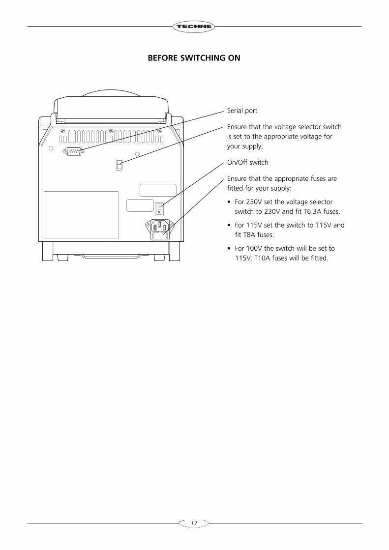
BEFORE SWITCHING ON
Serial port
Ensure that the voltage selector switchis set to the appropriate voltage foryour supply;
On/Off switch
Ensure that the appropriate fuses arefitted for your supply:
• For 230V set the voltage selectorswitch to 230V and fit T6.3A fuses.
• For 115V set the switch to 115V andfit T8A fuses.
• For 100V the switch will be set to115V; T10A fuses will be fitted.
18
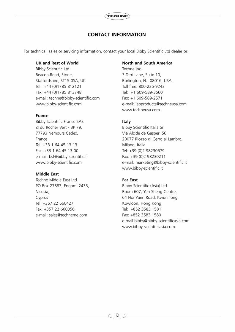
CONTACT INFORMATION
For technical, sales or servicing information, contact your local Bibby Scientific Ltd dealer or:
UK and Rest of WorldBibby Scientific LtdBeacon Road, Stone,Staffordshire, ST15 0SA, UKTel: +44 (0)1785 812121 Fax: +44 (0)1785 813748e-mail: [email protected]
FranceBibby Scientific France SASZI du Rocher Vert - BP 79,77793 Nemours Cedex,FranceTel: +33 1 64 45 13 13Fax: +33 1 64 45 13 00e-mail: [email protected]
Middle EastTechne Middle East Ltd.PO Box 27887, Engomi 2433,Nicosia,CyprusTel: +357 22 660427Fax: +357 22 660356e-mail: [email protected]
North and South AmericaTechne Inc.3 Terri Lane, Suite 10,Burlington, NJ, 08016, USAToll free: 800-225-9243Tel: +1 609-589-3560Fax: +1 609-589-2571e-mail: [email protected]
ItalyBibby Scientific Italia SrlVia Alcide de Gasperi 56,20077 Riozzo di Cerro al Lambro,Milano, ItaliaTel: +39 (0)2 98230679Fax: +39 (0)2 98230211e-mail: [email protected]
Far EastBibby Scientific (Asia) LtdRoom 607, Yen Sheng Centre,64 Hoi Yuen Road, Kwun Tong,Kowloon, Hong KongTel: +852 3583 1581Fax: +852 3583 1580e-mail [email protected]
TC-4000 SPECIFICATION
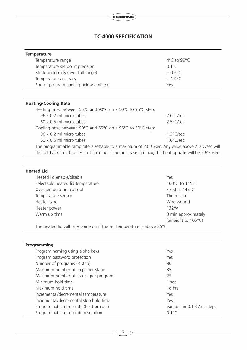
TemperatureTemperature range 4°C to 99°CTemperature set point precision 0.1°CBlock uniformity (over full range) ± 0.6°CTemperature accuracy ± 1.0°CEnd of program cooling below ambient Yes
Heating/Cooling RateHeating rate, between 55°C and 90°C on a 50°C to 95°C step:
96 x 0.2 ml micro tubes 2.6°C/sec60 x 0.5 ml micro tubes 2.5°C/sec
Cooling rate, between 90°C and 55°C on a 95°C to 50°C step:96 x 0.2 ml micro tubes 1.3°C/sec60 x 0.5 ml micro tubes 1.6°C/sec
The programmable ramp rate is settable to a maximum of 2.0°C/sec. Any value above 2.0°C/sec willdefault back to 2.0 unless set for max. If the unit is set to max, the heat up rate will be 2.6°C/sec.
Heated LidHeated lid enable/disable YesSelectable heated lid temperature 100°C to 115°COver-temperature cut-out Fixed at 145°C Temperature sensor ThermistorHeater type Wire woundHeater power 132WWarm up time 3 min approximately
(ambient to 105°C)The heated lid will only come on if the set temperature is above 35°C
ProgrammingProgram naming using alpha keys YesProgram password protection YesNumber of programs (3 step) 80Maximum number of steps per stage 35Maximum number of stages per program 25 Minimum hold time 1 secMaximum hold time 18 hrsIncremental/decremental temperature YesIncremental/decremental step hold time YesProgrammable ramp rate (heat or cool) Variable in 0.1°C/sec stepsProgrammable ramp rate resolution 0.1°C
19
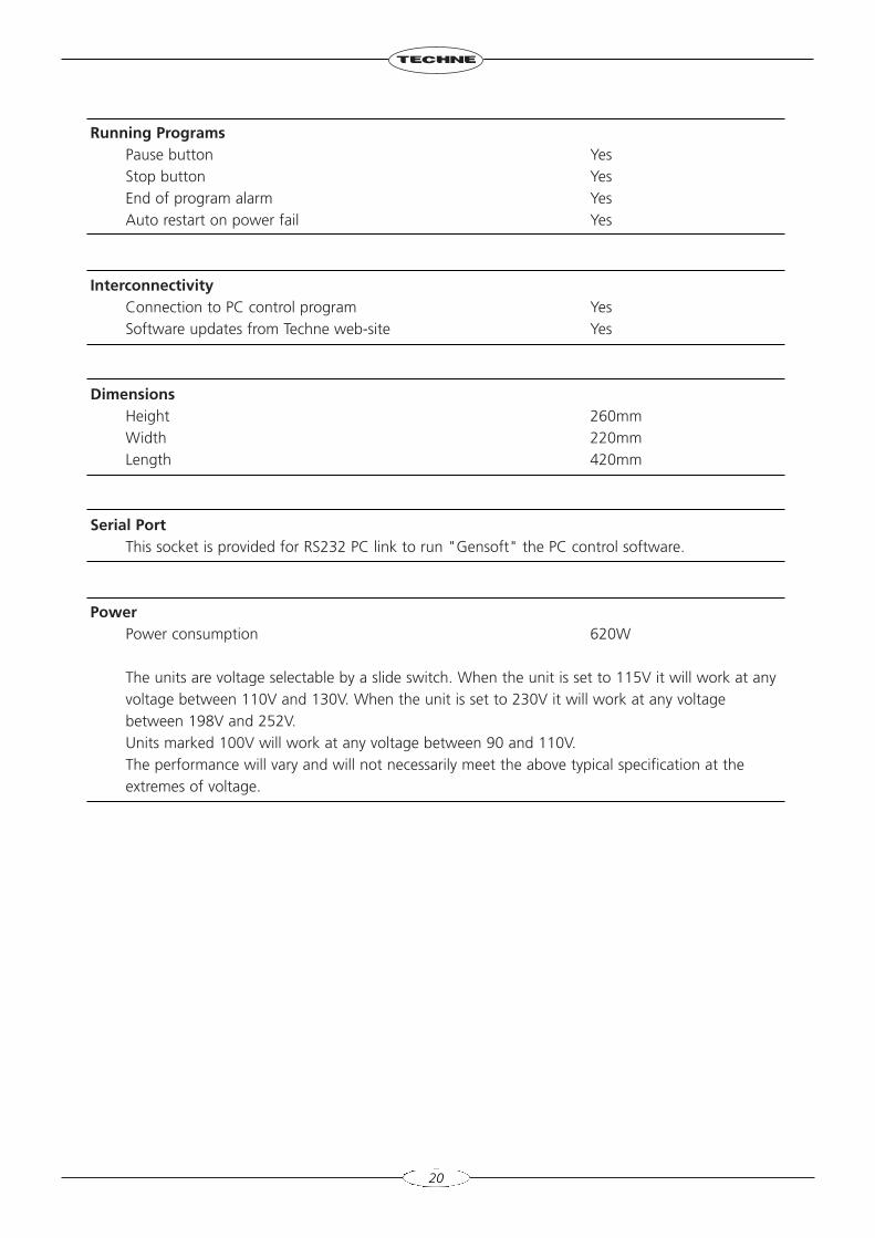
Running ProgramsPause button YesStop button YesEnd of program alarm YesAuto restart on power fail Yes
InterconnectivityConnection to PC control program YesSoftware updates from Techne web-site Yes
DimensionsHeight 260mmWidth 220mmLength 420mm
Serial PortThis socket is provided for RS232 PC link to run "Gensoft" the PC control software.
PowerPower consumption 620W
The units are voltage selectable by a slide switch. When the unit is set to 115V it will work at any voltage between 110V and 130V. When the unit is set to 230V it will work at any voltage between 198V and 252V. Units marked 100V will work at any voltage between 90 and 110V.The performance will vary and will not necessarily meet the above typical specification at the extremes of voltage.
20
USER OPERATION AND CONSUMABLES
HEATED LID
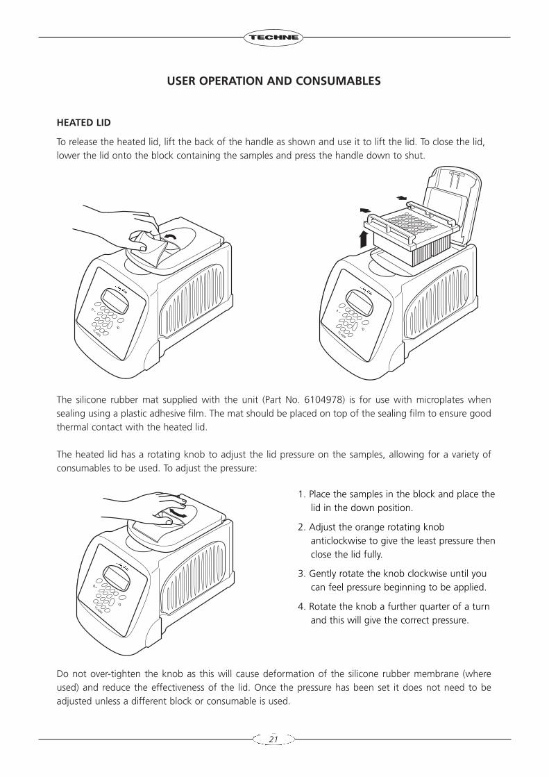
To release the heated lid, lift the back of the handle as shown and use it to lift the lid. To close the lid,lower the lid onto the block containing the samples and press the handle down to shut.
The silicone rubber mat supplied with the unit (Part No. 6104978) is for use with microplates whensealing using a plastic adhesive film. The mat should be placed on top of the sealing film to ensure goodthermal contact with the heated lid.
The heated lid has a rotating knob to adjust the lid pressure on the samples, allowing for a variety ofconsumables to be used. To adjust the pressure:
Do not over-tighten the knob as this will cause deformation of the silicone rubber membrane (whereused) and reduce the effectiveness of the lid. Once the pressure has been set it does not need to beadjusted unless a different block or consumable is used.
21
1. Place the samples in the block and place thelid in the down position.
2. Adjust the orange rotating knobanticlockwise to give the least pressure thenclose the lid fully.
3. Gently rotate the knob clockwise until youcan feel pressure beginning to be applied.
4. Rotate the knob a further quarter of a turnand this will give the correct pressure.
TUBES OR REACTION VESSELS
Techne does not recommend any specific tube or reaction vessel other than those described in thismanual. We recommend using reaction volumes between 20 and 200µl. The tubes must withstand apressure of 1 atmosphere at 100°C. Any vessel must be able to withstand the temperatures you are usingwithout any danger of them deforming to the point where they fracture.
To test your tubes, put 25µl of water into each of 5 tubes and subject them to a typical thermal cyclingprotocol. At the end of the program, measure the volume remaining using a micropipette. A loss of morethan 1 or 2µl indicates a vapour leak.
The amount of volume loss you observe and the change in reactant concentrations you can toleratedetermine the minimum volume that can be used. Typical volume losses of 1µl in 30 cycles allow the useof samples of 20µl or less.
During the final cool-down, a ring of condensation may form above the liquid level but below the top ofthe sample block. This is normal and does not effect the reaction.
SWITCHING ON
22
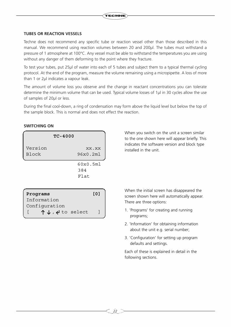
When you switch on the unit a screen similarto the one shown here will appear briefly. Thisindicates the software version and block typeinstalled in the unit.
When the initial screen has disappeared thescreen shown here will automatically appear.There are three options:
1. 'Programs' for creating and runningprograms;
2. 'Information' for obtaining informationabout the unit e.g. serial number;
3. 'Configuration' for setting up programdefaults and settings.
Each of these is explained in detail in thefollowing sections.
TC-4000
Version xx.xxBlock 96x0.2ml
Programs [0]InformationConfiguration[ , to select ]
60x0.5ml384Flat
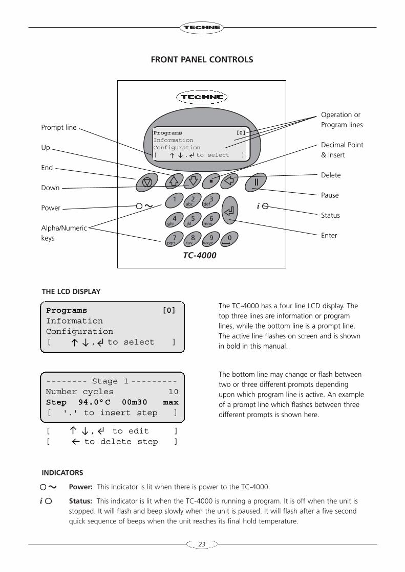
FRONT PANEL CONTROLS
THE LCD DISPLAY
INDICATORS
Power: This indicator is lit when there is power to the TC-4000.
Status: This indicator is lit when the TC-4000 is running a program. It is off when the unit is stopped. It will flash and beep slowly when the unit is paused. It will flash after a five second quick sequence of beeps when the unit reaches its final hold temperature.
7pqrs
8tuv
9wxyz
0
TC-4000
4ghi
5jkl
6mno
1 2abc
3def i
Programs [0]InformationConfiguration[ , to select ]
23
Operation orProgram lines
Decimal Point& Insert
Delete
Pause
Status
Enter
Prompt line
Up
End
Down
Power
Alpha/Numerickeys
The TC-4000 has a four line LCD display. Thetop three lines are information or programlines, while the bottom line is a prompt line.The active line flashes on screen and is shownin bold in this manual.
The bottom line may change or flash betweentwo or three different prompts dependingupon which program line is active. An exampleof a prompt line which flashes between threedifferent prompts is shown here.
i
Programs [0]InformationConfiguration[ , to select ]
-------- Stage 1 ---------Number cycles 10Step 94.0°C 00m30 max[ '.' to insert step ]
[ , to edit ][ to delete step ]
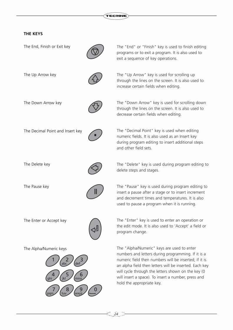
The "End" or "Finish" key is used to finish editingprograms or to exit a program. It is also used toexit a sequence of key operations.
The "Up Arrow" key is used for scrolling upthrough the lines on the screen. It is also used toincrease certain fields when editing.
The "Down Arrow" key is used for scrolling downthrough the lines on the screen. It is also used todecrease certain fields when editing.
The "Decimal Point" key is used when editingnumeric fields. It is also used as an Insert keyduring program editing to insert additional stepsand other field sets.
The "Delete" key is used during program editing todelete steps and stages.
The "Pause" key is used during program editing toinsert a pause after a stage or to insert incrementand decrement times and temperatures. It is alsoused to pause a program when it is running.
The "Enter" key is used to enter an operation orthe edit mode. It is also used to 'Accept' a field orprogram change.
The "Alpha/Numeric" keys are used to enternumbers and letters during programming. If it is anumeric field then numbers will be inserted; if it isan alpha field then letters will be inserted. Each keywill cycle through the letters shown on the key (0will insert a space). To insert a number, press andhold the appropriate key.
24
The End, Finish or Exit key
The Up Arrow key
The Down Arrow key
The Decimal Point and Insert key
The Delete key
The Pause key
The Enter or Accept key
The Alpha/Numeric keys
7pqrs
8tuv
9wxyz
0
4ghi
5jkl
6mno
1 2abc
3def
THE KEYS
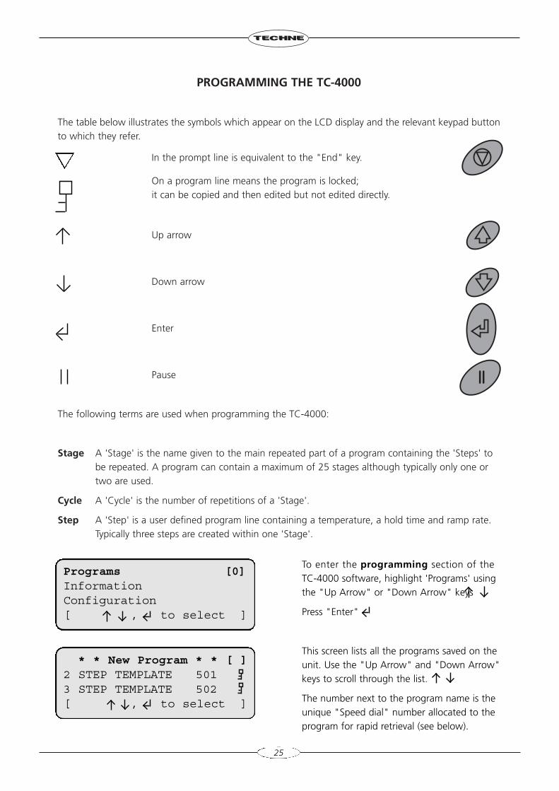
PROGRAMMING THE TC-4000
The table below illustrates the symbols which appear on the LCD display and the relevant keypad buttonto which they refer.
In the prompt line is equivalent to the "End" key.
On a program line means the program is locked;it can be copied and then edited but not edited directly.
Up arrow
Down arrow
Enter
Pause
The following terms are used when programming the TC-4000:
Stage A 'Stage' is the name given to the main repeated part of a program containing the 'Steps' tobe repeated. A program can contain a maximum of 25 stages although typically only one ortwo are used.
Cycle A 'Cycle' is the number of repetitions of a 'Stage'.
Step A 'Step' is a user defined program line containing a temperature, a hold time and ramp rate.Typically three steps are created within one 'Stage'.
25
To enter the programming section of theTC-4000 software, highlight 'Programs' usingthe "Up Arrow" or "Down Arrow" keys
Press "Enter"
This screen lists all the programs saved on theunit. Use the "Up Arrow" and "Down Arrow"keys to scroll through the list.
The number next to the program name is theunique "Speed dial" number allocated to theprogram for rapid retrieval (see below).
Programs [0]InformationConfiguration[ , to select ]
* * New Program * * [ ]2 STEP TEMPLATE 5013 STEP TEMPLATE 502[ , to select ]
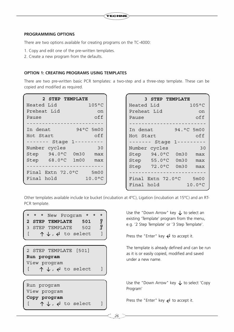
PROGRAMMING OPTIONS
There are two options available for creating programs on the TC-4000:
1. Copy and edit one of the pre-written templates.2. Create a new program from the defaults.
OPTION 1: CREATING PROGRAMS USING TEMPLATES
There are two pre-written basic PCR templates: a two-step and a three-step template. These can becopied and modified as required.
Other templates available include Ice bucket (incubation at 4ºC), Ligation (incubation at 15ºC) and an RT-PCR template.
26
Use the "Down Arrow" key to select anexisting 'Template' program from the menu,e.g. '2 Step Template' or '3 Step Template'.
Press the "Enter" key to accept it.
The template is already defined and can be runas it is or easily copied, modified and savedunder a new name.
Use the "Down Arrow" key to select 'CopyProgram'
Press the "Enter" key to accept it.
2 STEP TEMPLATE [501]Run programView program[ , to select ]
2 STEP TEMPLATEHeated Lid 105°CPreheat Lid onPause off-------------------------In denat 94°C 5m00Hot Start off------- Stage 1---------Number cycles 30Step 94.0°C 0m30 maxStep 68.0°C 1m00 max-------------------------Final Extn 72.0°C 5m00Final hold 10.0°C
3 STEP TEMPLATEHeated Lid 105°CPreheat Lid onPause off-------------------------In denat 94.°C 5m00Hot Start off------- Stage 1---------Number cycles 30Step 94.0°C 0m30 maxStep 55.0°C 0m30 maxStep 72.0°C 0m30 max-------------------------Final Extn 72.0°C 5m00Final hold 10.0°C
Run programView programCopy program[ , to select ]
* * * New Program * * * 2 STEP TEMPLATE 5013 STEP TEMPLATE 502[ , to select ]
To save the program
[ to save ]
[ YES or NO ]
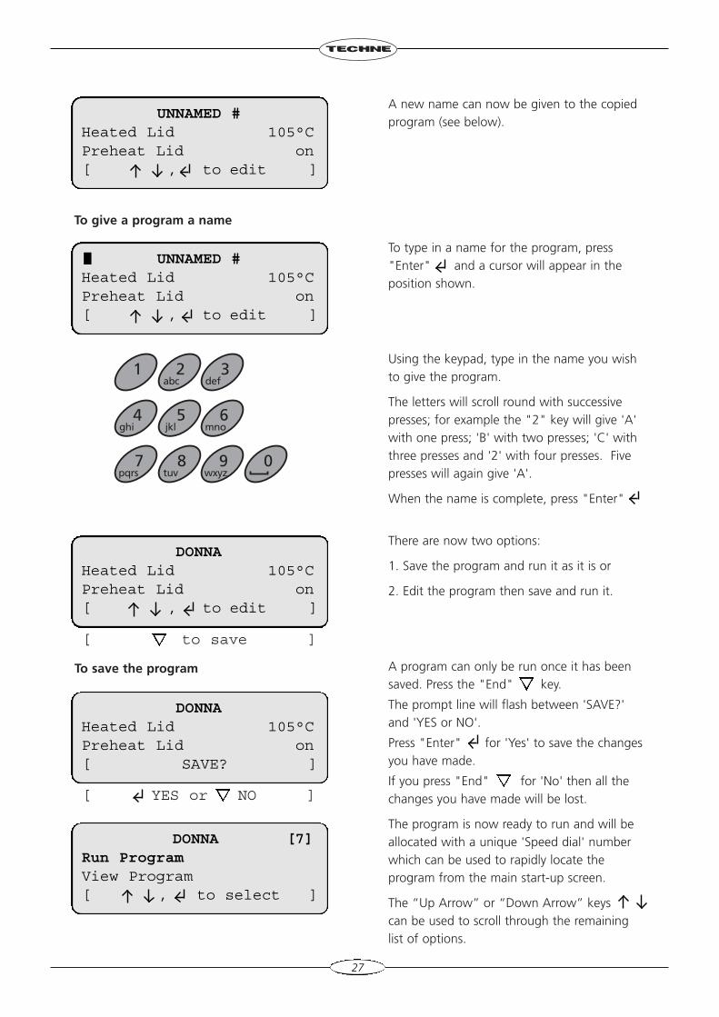
To give a program a name
A new name can now be given to the copiedprogram (see below).
To type in a name for the program, press"Enter" and a cursor will appear in theposition shown.
Using the keypad, type in the name you wishto give the program.
The letters will scroll round with successivepresses; for example the "2" key will give 'A'with one press; 'B' with two presses; 'C' withthree presses and '2' with four presses. Fivepresses will again give 'A'.
When the name is complete, press "Enter"
There are now two options:
1. Save the program and run it as it is or
2. Edit the program then save and run it.
A program can only be run once it has beensaved. Press the "End" key.
The prompt line will flash between 'SAVE?'and 'YES or NO'.
Press "Enter" for 'Yes' to save the changesyou have made.
If you press "End" for 'No' then all thechanges you have made will be lost.
The program is now ready to run and will beallocated with a unique 'Speed dial' numberwhich can be used to rapidly locate theprogram from the main start-up screen.
The “Up Arrow” or “Down Arrow” keyscan be used to scroll through the remaininglist of options.
27
UNNAMED #Heated Lid 105°CPreheat Lid on[ , to edit ]
UNNAMED #Heated Lid 105°CPreheat Lid on[ , to edit ]
DONNAHeated Lid 105°CPreheat Lid on[ , to edit ]
7pqrs
8tuv
9wxyz
0
4ghi
5jkl
6mno
1 2abc
3def
DONNAHeated Lid 105°CPreheat Lid on[ SAVE? ]
DONNA [7]Run ProgramView Program[ , to select ]
Edit a selected field or step
DONNAHeated Lid 105°CPreheat Lid on[ , to edit ]
28
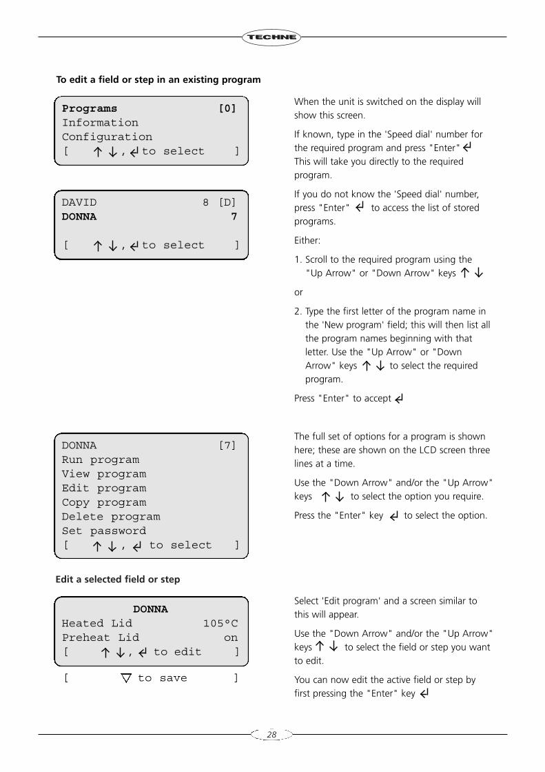
To edit a field or step in an existing program
When the unit is switched on the display willshow this screen.
If known, type in the 'Speed dial' number forthe required program and press "Enter"This will take you directly to the requiredprogram.
If you do not know the 'Speed dial' number,press "Enter" to access the list of storedprograms.
Either:
1. Scroll to the required program using the"Up Arrow" or "Down Arrow" keys
or
2. Type the first letter of the program name inthe 'New program' field; this will then list allthe program names beginning with thatletter. Use the "Up Arrow" or "DownArrow" keys to select the requiredprogram.
Press "Enter" to accept
The full set of options for a program is shownhere; these are shown on the LCD screen threelines at a time.
Use the "Down Arrow" and/or the "Up Arrow"keys to select the option you require.
Press the "Enter" key to select the option.
Select 'Edit program' and a screen similar tothis will appear.
Use the "Down Arrow" and/or the "Up Arrow"keys to select the field or step you wantto edit.
You can now edit the active field or step byfirst pressing the "Enter" key
Programs [0]InformationConfiguration[ , to select ]
DAVID 8 [D]DONNA 7
[ , to select ]
DONNA [7]Run programView programEdit programCopy programDelete programSet password[ , to select ]
[ to save ]
[ to disable ]
[ turn on/off ]
29
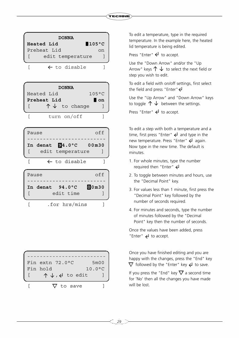
To edit a temperature, type in the requiredtemperature. In the example here, the heatedlid temperature is being edited.
Press "Enter" to accept.
Use the "Down Arrow" and/or the "UpArrow" keys to select the next field orstep you wish to edit.
To edit a field with on/off settings, first selectthe field and press "Enter"
Use the "Up Arrow" and "Down Arrow" keysto toggle between the settings.
Press "Enter" to accept.
To edit a step with both a temperature and atime, first press "Enter" and type in thenew temperature. Press "Enter" again.Now type in the new time. The default isminutes.
1. For whole minutes, type the numberrequired then "Enter"
2. To toggle between minutes and hours, usethe "Decimal Point" key.
3. For values less than 1 minute, first press the"Decimal Point" key followed by thenumber of seconds required.
4. For minutes and seconds, type the numberof minutes followed by the "DecimalPoint" key then the number of seconds.
Once the values have been added, press"Enter" to accept.
Once you have finished editing and you arehappy with the changes, press the "End" key
followed by the "Enter" key to save.
If you press the "End" key a second timefor 'No' then all the changes you have madewill be lost.
DONNAHeated Lid 105°CPreheat Lid on[ edit temperature ]
DONNAHeated Lid 105°CPreheat Lid on[ to change ]
[ to disable ]
[ .for hrs/mins ]
Pause off-------------------------In denat 4.0°C 00m30[ edit temperature ]
9
Pause off-------------------------In denat 94.0°C 0m30[ edit time ]
0
-------------------------Fin extn 72.0°C 5m00Fin hold 10.0°C[ , to edit ]
[ to save ]
[ to exit ]
[ Yes or No ]
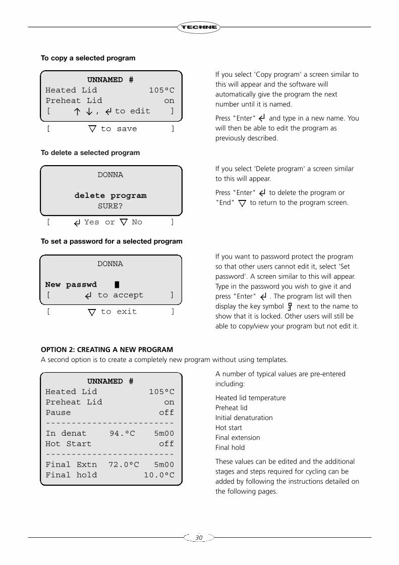
To delete a selected program
30
OPTION 2: CREATING A NEW PROGRAMA second option is to create a completely new program without using templates.
If you select 'Copy program' a screen similar tothis will appear and the software willautomatically give the program the nextnumber until it is named.
Press "Enter" and type in a new name. Youwill then be able to edit the program aspreviously described.
If you select 'Delete program' a screen similarto this will appear.
Press "Enter" to delete the program or"End" to return to the program screen.
If you want to password protect the programso that other users cannot edit it, select 'Setpassword'. A screen similar to this will appear.Type in the password you wish to give it andpress "Enter" . The program list will thendisplay the key symbol next to the name toshow that it is locked. Other users will still beable to copy/view your program but not edit it.
A number of typical values are pre-enteredincluding:
Heated lid temperature Preheat lid Initial denaturation Hot startFinal extensionFinal hold
These values can be edited and the additionalstages and steps required for cycling can beadded by following the instructions detailed onthe following pages.
UNNAMED #Heated Lid 105°CPreheat Lid on[ , to edit ]
DONNA
delete programSURE?
DONNA
New passwd[ to accept ]
UNNAMED #Heated Lid 105°CPreheat Lid onPause off-------------------------In denat 94.°C 5m00Hot Start off-------------------------Final Extn 72.0°C 5m00Final hold 10.0°C
To copy a selected program
To set a password for a selected program
[ to save ]
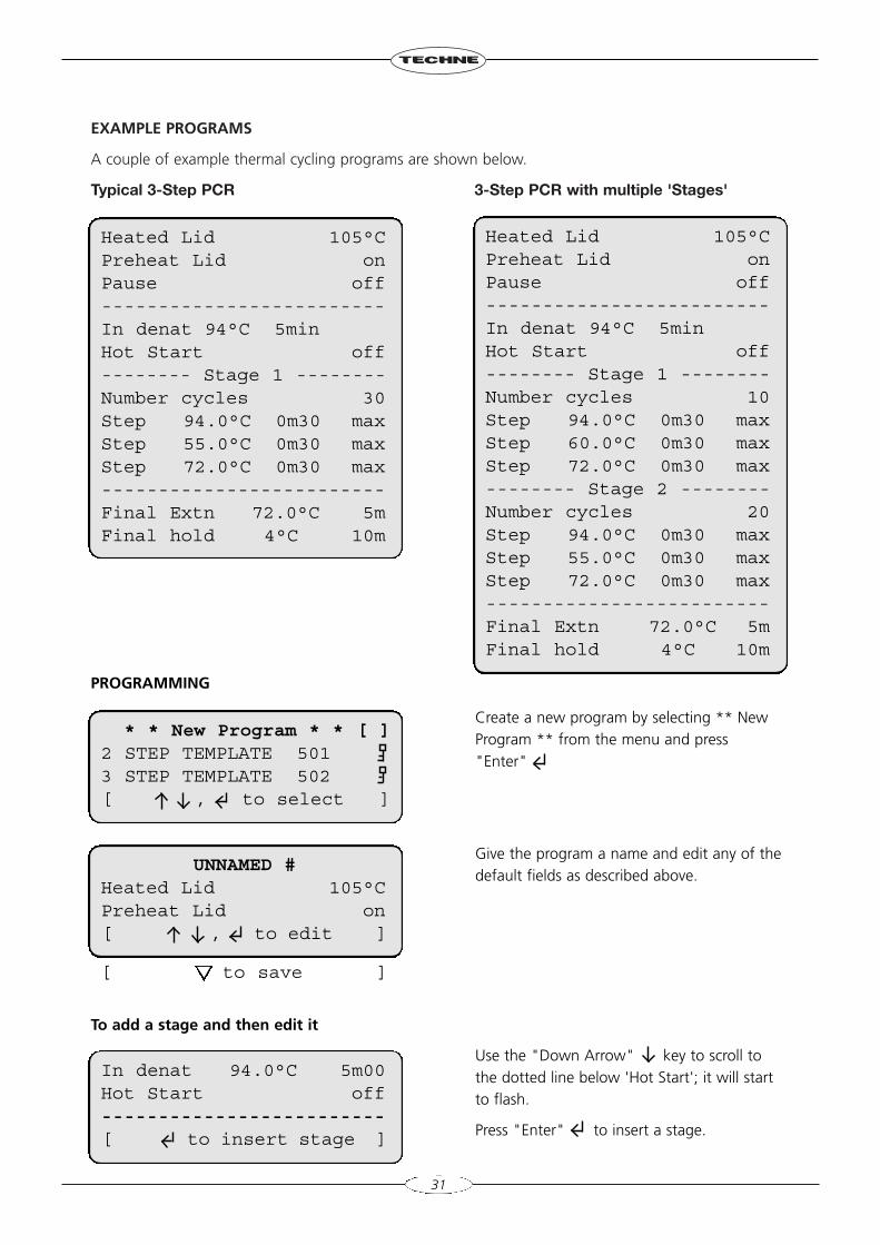
EXAMPLE PROGRAMS
A couple of example thermal cycling programs are shown below.
Typical 3-Step PCR 3-Step PCR with multiple 'Stages'
31
PROGRAMMING
To add a stage and then edit it
Heated Lid 105°CPreheat Lid onPause off-------------------------In denat 94°C 5minHot Start off-------- Stage 1 --------Number cycles 30Step 94.0°C 0m30 maxStep 55.0°C 0m30 maxStep 72.0°C 0m30 max-------------------------Final Extn 72.0°C 5mFinal hold 4°C 10m
Heated Lid 105°CPreheat Lid onPause off-------------------------In denat 94°C 5minHot Start off-------- Stage 1 --------Number cycles 10Step 94.0°C 0m30 maxStep 60.0°C 0m30 maxStep 72.0°C 0m30 max-------- Stage 2 --------Number cycles 20Step 94.0°C 0m30 maxStep 55.0°C 0m30 maxStep 72.0°C 0m30 max-------------------------Final Extn 72.0°C 5mFinal hold 4°C 10m
Create a new program by selecting ** NewProgram ** from the menu and press"Enter"
Give the program a name and edit any of thedefault fields as described above.
Use the "Down Arrow" key to scroll tothe dotted line below 'Hot Start'; it will startto flash.
Press "Enter" to insert a stage.
* * New Program * * [ ]2 STEP TEMPLATE 5013 STEP TEMPLATE 502[ , to select ]
UNNAMED #Heated Lid 105°CPreheat Lid on[ , to edit ]
In denat 94.0°C 5m00Hot Start off-------------------------[ to insert stage ]
[ to save ]
[ , to edit ][ to delete step ]
[ , to edit ]
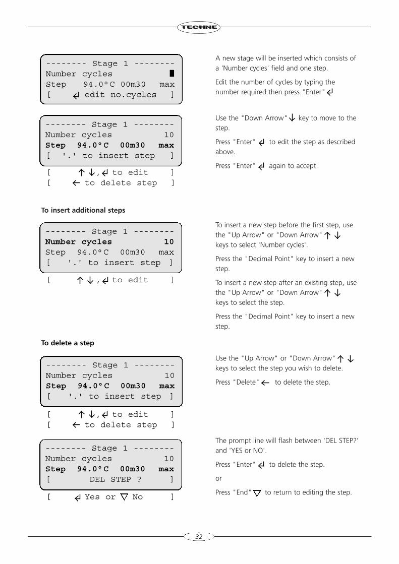
To insert additional steps
A new stage will be inserted which consists ofa 'Number cycles' field and one step.
Edit the number of cycles by typing thenumber required then press "Enter"
Use the "Down Arrow" key to move to thestep.
Press "Enter" to edit the step as describedabove.
Press "Enter" again to accept.
To insert a new step before the first step, usethe "Up Arrow" or "Down Arrow"keys to select 'Number cycles'.
Press the "Decimal Point" key to insert a newstep.
To insert a new step after an existing step, usethe "Up Arrow" or "Down Arrow"keys to select the step.
Press the "Decimal Point" key to insert a newstep.
Use the "Up Arrow" or "Down Arrow"keys to select the step you wish to delete.
Press "Delete" to delete the step.
The prompt line will flash between 'DEL STEP?'and 'YES or NO'.
Press "Enter" to delete the step.
or
Press "End" to return to editing the step.
32
-------- Stage 1 --------Number cyclesStep 94.0°C 00m30 max[ edit no.cycles ]
-------- Stage 1 --------Number cycles 10Step 94.0°C 00m30 max[ '.' to insert step ]
-------- Stage 1 --------Number cycles 10Step 94.0°C 00m30 max[ '.' to insert step ]
-------- Stage 1 --------Number cycles 10Step 94.0°C 00m30 max[ DEL STEP ? ]
To delete a step
-------- Stage 1 --------Number cycles 10Step 94.0°C 00m30 max[ '.' to insert step ]
[ , to edit ][ to delete step ]
[ Yes or No ]
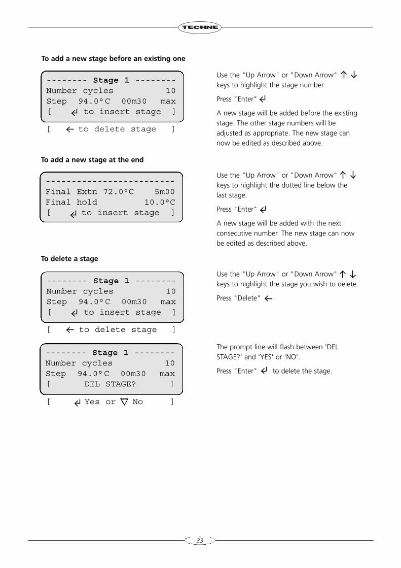
[ to delete stage ]
-------------------------Final Extn 72.0°C 5m00Final hold 10.0°C[ to insert stage ]
Use the "Up Arrow" or "Down Arrow"keys to highlight the stage number.
Press "Enter"
A new stage will be added before the existingstage. The other stage numbers will beadjusted as appropriate. The new stage cannow be edited as described above.
Use the "Up Arrow" or "Down Arrow"keys to highlight the dotted line below thelast stage.
Press "Enter"
A new stage will be added with the nextconsecutive number. The new stage can nowbe edited as described above.
Use the "Up Arrow" or "Down Arrow"keys to highlight the stage you wish to delete.
Press "Delete"
The prompt line will flash between 'DELSTAGE?' and 'YES' or 'NO'.
Press "Enter" to delete the stage.
To add a new stage before an existing one
To add a new stage at the end
To delete a stage
33
-------- Stage 1 --------Number cycles 10Step 94.0°C 00m30 max[ to insert stage ]
[ to delete stage ]
-------- Stage 1 --------Number cycles 10Step 94.0°C 00m30 max[ to insert stage ]
-------- Stage 1 --------Number cycles 10Step 94.0°C 00m30 max[ DEL STAGE? ]
[ Yes or No ]
[ ‘.’ to insert step ][ , to edit ]
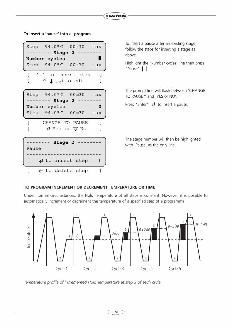
TO PROGRAM INCREMENT OR DECREMENT TEMPERATURE OR TIME
Under normal circumstances, the Hold Temperature of all steps is constant. However, it is possible toautomatically increment or decrement the temperature of a specified step of a programme.
Temperature profile of incremented Hold Temperature at step 3 of each cycle
34
To insert a pause after an existing stage,follow the steps for inserting a stage asabove.
Highlight the 'Number cycles' line then press"Pause"
The prompt line will flash between 'CHANGETO PAUSE?' and 'YES or NO'.
Press "Enter" to insert a pause.
The stage number will then be highlightedwith 'Pause' as the only line.
To insert a ‘pause’ into a program
Step 94.0°C 00m30 max-------- Stage 2 --------Number cyclesStep 94.0°C 00m30 max
[ CHANGE TO PAUSE ][ Yes or No ]
Step 94.0°C 00m30 max-------- Stage 2 --------Number cycles 0Step 94.0°C 00m30 max
-------- Stage 2 --------Pause-------------------------[ to insert step ]
Cycle 1
2 2 2 2 2
3
1
3
1
3
1
3
1
3
11
Cycle 2 Cycle 3 Cycle 4 Cycle 5
O+4∂OO+3∂OO+2∂O
O+∂OO
Tem
pera
ture
[ to delete step ]
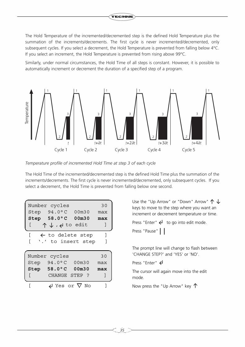
The Hold Temperature of the incremented/decremented step is the defined Hold Temperature plus thesummation of the increments/decrements. The first cycle is never incremented/decremented, onlysubsequent cycles. If you select a decrement, the Hold Temperature is prevented from falling below 4°C.If you select an increment, the Hold Temperature is prevented from rising above 99°C.
Similarly, under normal circumstances, the Hold Time of all steps is constant. However, it is possible toautomatically increment or decrement the duration of a specified step of a program.
Temperature profile of incremented Hold Time at step 3 of each cycle
The Hold Time of the incremented/decremented step is the defined Hold Time plus the summation of theincrements/decrements. The first cycle is never incremented/decremented, only subsequent cycles. If youselect a decrement, the Hold Time is prevented from falling below one second.
35
Use the "Up Arrow" or "Down" Arrow"keys to move to the step where you want anincrement or decrement temperature or time.
Press "Enter" to go into edit mode.
Press "Pause"
The prompt line will change to flash between'CHANGE STEP?' and 'YES' or 'NO'.
Press "Enter"
The cursor will again move into the editmode.
Now press the "Up Arrow" key
Number cycles 30Step 94.0°C 00m30 maxStep 58.0°C 00m30 max[ , to edit ]
Number cycles 30Step 94.0°C 00m30 maxStep 58.0°C 00m30 max[ CHANGE STEP ? ]
Cycle 1
2 2 2 2 2
3
1
3
1
3
1
3
1
3
11
Cycle 2 Cycle 3 Cycle 4 Cycle 5
t+3∂t
Tem
pera
ture
t+4∂tt+2∂tt+∂tt
[ Yes or No ]
[ to delete step ][ ‘.’ to insert step ]
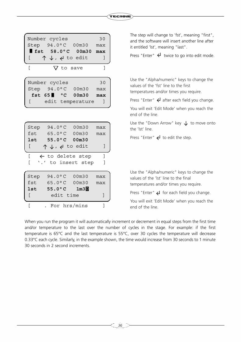
Use the "Alpha/numeric" keys to change thevalues of the 'fst' line to the firsttemperatures and/or times you require.
Press "Enter" after each field you change.
You will exit 'Edit Mode' when you reach theend of the line.
Use the "Down Arrow" key to move ontothe 'lst' line.
Press "Enter" to edit the step.
Use the "Alpha/numeric" keys to change thevalues of the 'lst' line to the finaltemperatures and/or times you require.
Press "Enter" for each field you change.
You will exit 'Edit Mode' when you reach theend of the line.
36
Number cycles 30Step 94.0°C 00m30 maxfst 65 °C 00m30 max
[ edit temperature ]
Step 94.0°C 00m30 maxfst 65.0°C 00m30 maxlst 55.0°C 00m30[ , to edit ]
Step 94.0°C 00m30 maxfst 65.0°C 00m30 maxlst 55.0°C 1m3 [ edit time ]
Number cycles 30Step 94.0°C 00m30 max
fst 58.0°C 00m30 max[ , to edit ]
The step will change to 'fst', meaning "first",and the software will insert another line afterit entitled 'lst', meaning "last".
Press "Enter" twice to go into edit mode.
When you run the program it will automatically increment or decrement in equal steps from the first timeand/or temperature to the last over the number of cycles in the stage. For example: if the firsttemperature is 65°C and the last temperature is 55°C, over 30 cycles the temperature will decrease0.33°C each cycle. Similarly, in the example shown, the time would increase from 30 seconds to 1 minute30 seconds in 2 second increments.
[ to save ]
[ to delete step ][ ‘.’ to insert step ]
[ . For hrs/mins ]
0
At any time during programming the TC-4000, when you are satisfied with the program, you can finishand accept what you have done by first pressing the "End" key.
Then follow the instructions on screen. If you are not sure, wait for the instructions in the prompt line toscroll back to the first line that you see.
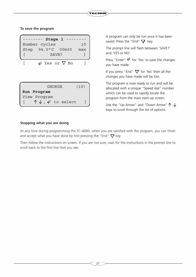
To save the program
Stopping what you are doing
37
A program can only be run once it has beensaved. Press the "End" key.
The prompt line will flash between 'SAVE?'and 'YES or NO'.
Press "Enter" for 'Yes' to save the changesyou have made.
If you press "End" for 'No' then all thechanges you have made will be lost.
The program is now ready to run and will beallocated with a unique "Speed dial" numberwhich can be used to rapidly locate theprogram from the main start-up screen.
Use the "Up Arrow" and "Down Arrow"keys to scroll through the list of options.
-------- Stage 1 --------Number cycles 10Step 94.0°C 00m30 max[ SAVE? ]
GEORGE (10)Run ProgramView Program[ , to select ]
[ Yes or No ]
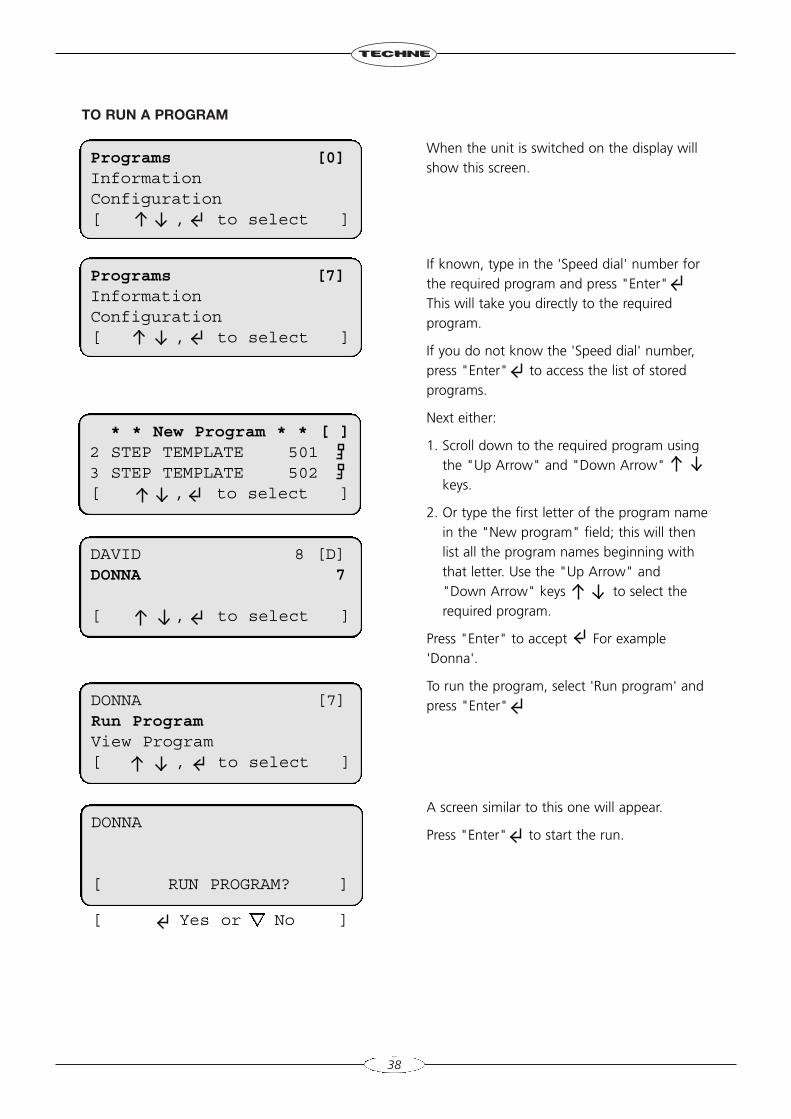
TO RUN A PROGRAM
38
When the unit is switched on the display willshow this screen.
If known, type in the 'Speed dial' number forthe required program and press "Enter"This will take you directly to the requiredprogram.
If you do not know the 'Speed dial' number,press "Enter" to access the list of storedprograms.
Next either:
1. Scroll down to the required program usingthe "Up Arrow" and "Down Arrow"keys.
2. Or type the first letter of the program namein the "New program" field; this will thenlist all the program names beginning withthat letter. Use the "Up Arrow" and"Down Arrow" keys to select therequired program.
Press "Enter" to accept For example'Donna'.
To run the program, select 'Run program' andpress "Enter"
A screen similar to this one will appear.
Press "Enter" to start the run.
Programs [0]InformationConfiguration[ , to select ]
Programs [7]InformationConfiguration[ , to select ]
* * New Program * * [ ]2 STEP TEMPLATE 5013 STEP TEMPLATE 502[ , to select ]
DAVID 8 [D]DONNA 7
[ , to select ]
DONNA [7]Run ProgramView Program[ , to select ]
DONNA
[ RUN PROGRAM? ]
[ Yes or No ]
[ to CONTINUE ][ for info ]
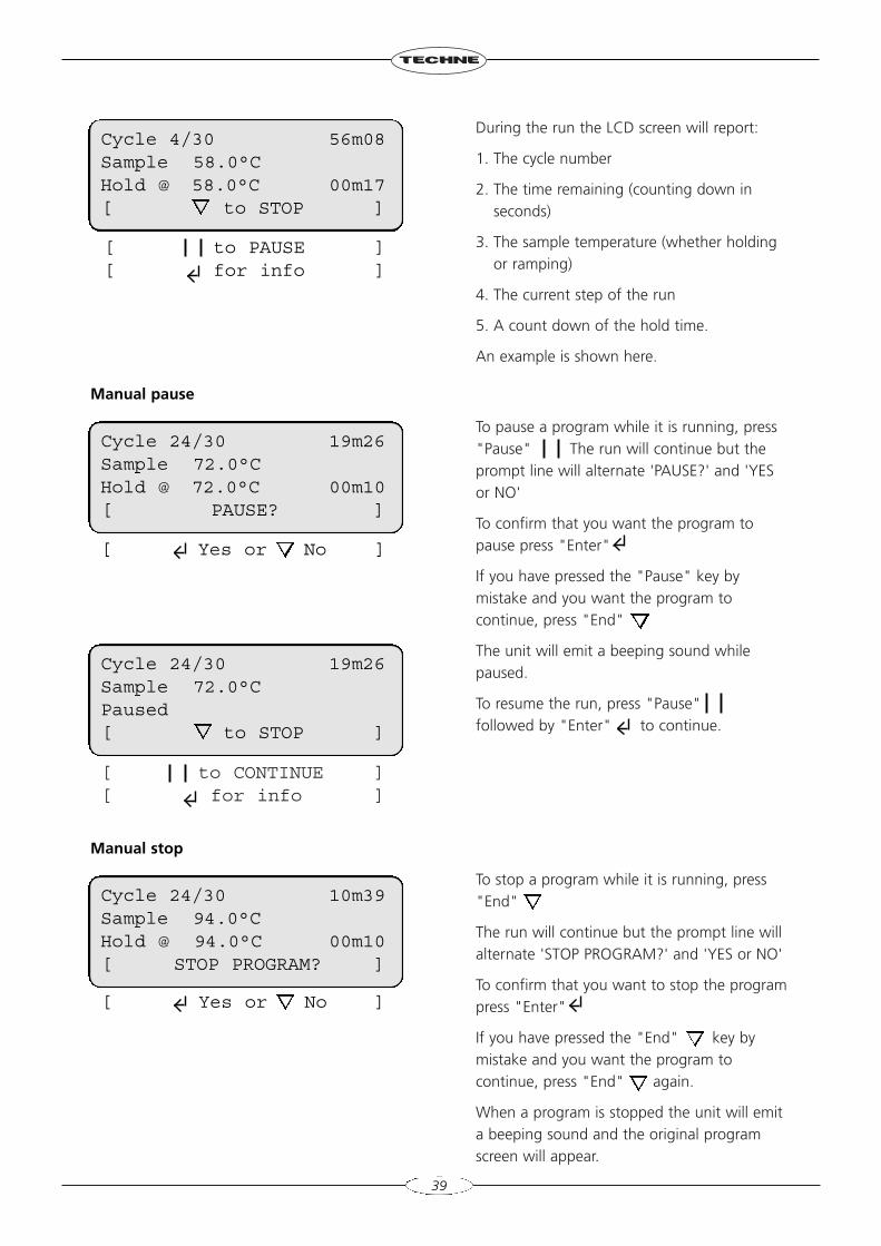
During the run the LCD screen will report:
1. The cycle number
2. The time remaining (counting down inseconds)
3. The sample temperature (whether holdingor ramping)
4. The current step of the run
5. A count down of the hold time.
An example is shown here.
To pause a program while it is running, press"Pause" The run will continue but theprompt line will alternate 'PAUSE?' and 'YESor NO'
To confirm that you want the program topause press "Enter"
If you have pressed the "Pause" key bymistake and you want the program tocontinue, press "End"
The unit will emit a beeping sound whilepaused.
To resume the run, press "Pause"followed by "Enter" to continue.
To stop a program while it is running, press"End"
The run will continue but the prompt line willalternate 'STOP PROGRAM?' and 'YES or NO'
To confirm that you want to stop the programpress "Enter"
If you have pressed the "End" key bymistake and you want the program tocontinue, press "End" again.
When a program is stopped the unit will emita beeping sound and the original programscreen will appear.
39
Manual pause
Manual stop
Cycle 4/30 56m08Sample 58.0°CHold @ 58.0°C 00m17[ to STOP ]
Cycle 24/30 19m26Sample 72.0°CHold @ 72.0°C 00m10[ PAUSE? ]
Cycle 24/30 19m26Sample 72.0°CPaused[ to STOP ]
Cycle 24/30 10m39Sample 94.0°CHold @ 94.0°C 00m10[ STOP PROGRAM? ]
[ Yes or No ]
[ Yes or No ]
[ to PAUSE ][ for info ]
CONFIGURATION
Password pad[ to accept ]
40
Program Information
INFORMATION
CONFIGURATION
Warning! The Configuration software should only be accessed by designated personnel, as someparameters can be changed or may be lost when using it.
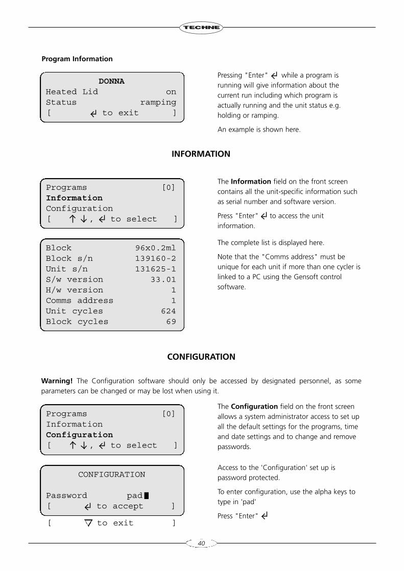
Pressing "Enter" while a program isrunning will give information about thecurrent run including which program isactually running and the unit status e.g.holding or ramping.
An example is shown here.
The Information field on the front screencontains all the unit-specific information suchas serial number and software version.
Press "Enter" to access the unitinformation.
The complete list is displayed here.
Note that the "Comms address" must beunique for each unit if more than one cycler islinked to a PC using the Gensoft controlsoftware.
The Configuration field on the front screenallows a system administrator access to set upall the default settings for the programs, timeand date settings and to change and removepasswords.
Access to the 'Configuration' set up ispassword protected.
To enter configuration, use the alpha keys totype in 'pad'
Press "Enter"
Programs [0]InformationConfiguration[ , to select ]
Block 96x0.2mlBlock s/n 139160-2Unit s/n 131625-1S/w version 33.01H/w version 1Comms address 1Unit cycles 624Block cycles 69
DONNAHeated Lid onStatus ramping[ to exit ]
Programs [0]InformationConfiguration[ , to select ]
[ to exit ]
41
Program defaults
Settings
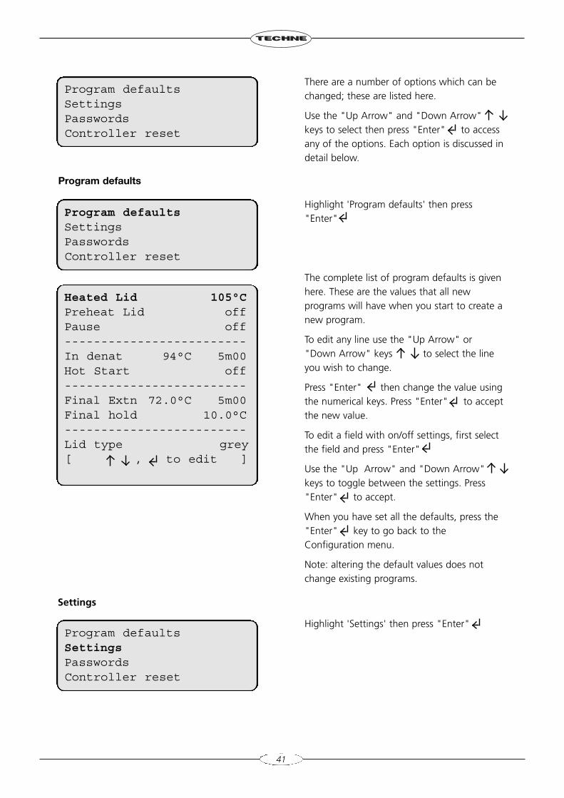
There are a number of options which can bechanged; these are listed here.
Use the "Up Arrow" and "Down Arrow"keys to select then press "Enter" to accessany of the options. Each option is discussed indetail below.
Highlight 'Program defaults' then press"Enter"
The complete list of program defaults is givenhere. These are the values that all newprograms will have when you start to create anew program.
To edit any line use the "Up Arrow" or"Down Arrow" keys to select the lineyou wish to change.
Press "Enter" then change the value usingthe numerical keys. Press "Enter" to acceptthe new value.
To edit a field with on/off settings, first selectthe field and press "Enter"
Use the "Up Arrow" and "Down Arrow"keys to toggle between the settings. Press"Enter" to accept.
When you have set all the defaults, press the"Enter" key to go back to theConfiguration menu.
Note: altering the default values does notchange existing programs.
Highlight 'Settings' then press "Enter"
Program defaultsSettingsPasswordsController reset
Program defaultsSettingsPasswordsController reset
Program defaultsSettingsPasswordsController reset
Heated Lid 105°CPreheat Lid offPause off-------------------------In denat 94°C 5m00Hot Start off-------------------------Final Extn 72.0°C 5m00Final hold 10.0°C-------------------------Lid type grey[ , to edit ]
42
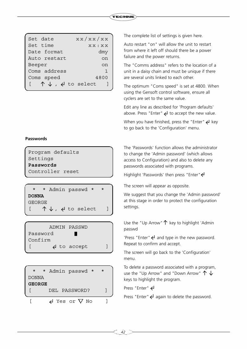
The complete list of settings is given here.
Auto restart "on" will allow the unit to restartfrom where it left off should there be a powerfailure and the power returns.
The "Comms address" refers to the location of aunit in a daisy chain and must be unique if thereare several units linked to each other.
The optimum "Coms speed" is set at 4800. Whenusing the Gensoft control software, ensure allcyclers are set to the same value.
Edit any line as described for 'Program defaults'above. Press "Enter" to accept the new value.
When you have finished, press the "Enter" keyto go back to the 'Configuration' menu.
The 'Passwords' function allows the administratorto change the 'Admin password' (which allowsaccess to Configuration) and also to delete anypasswords associated with programs.
Highlight 'Passwords' then press "Enter"
The screen will appear as opposite.
We suggest that you change the 'Admin password'at this stage in order to protect the configurationsettings.
Use the "Up Arrow" key to highlight 'Adminpasswd
'Press "Enter" and type in the new password.Repeat to confirm and accept.
The screen will go back to the 'Configuration'menu.
To delete a password associated with a program,use the "Up Arrow" and "Down Arrow"keys to highlight the program.
Press "Enter"
Press "Enter" again to delete the password.
Passwords
Set date xx/xx/xxSet time xx:xxDate format dmyAuto restart onBeeper onComs address 1Coms speed 4800[ , to select ]
Program defaultsSettingsPasswordsController reset
* * Admin passwd * *DONNAGEORGE[ , to select ]
* * Admin passwd * *DONNAGEORGE[ DEL PASSWORD? ]
ADMIN PASSWDPasswordConfirm[ to accept ]
[ Yes or No ]
43
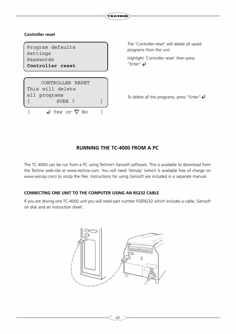
Controller reset
The 'Controller reset' will delete all savedprograms from the unit.
Highlight 'Controller reset' then press"Enter"
To delete all the programs, press "Enter"
RUNNING THE TC-4000 FROM A PC
The TC-4000 can be run from a PC using Techne’s Gensoft software. This is available to download fromthe Techne web-site at www.techne.com. You will need 'Winzip' (which is available free of charge onwww.winzip.com) to unzip the files. Instructions for using Gensoft are included in a separate manual.
CONNECTING ONE UNIT TO THE COMPUTER USING AN RS232 CABLE
If you are driving one TC-4000 unit you will need part number FGEN232 which includes a cable, Gensofton disk and an instruction sheet.
Program defaultsSettingsPasswordsController reset
CONTROLLER RESETThis will deleteall programs[ SURE ? ]
[ Yes or No ]
44
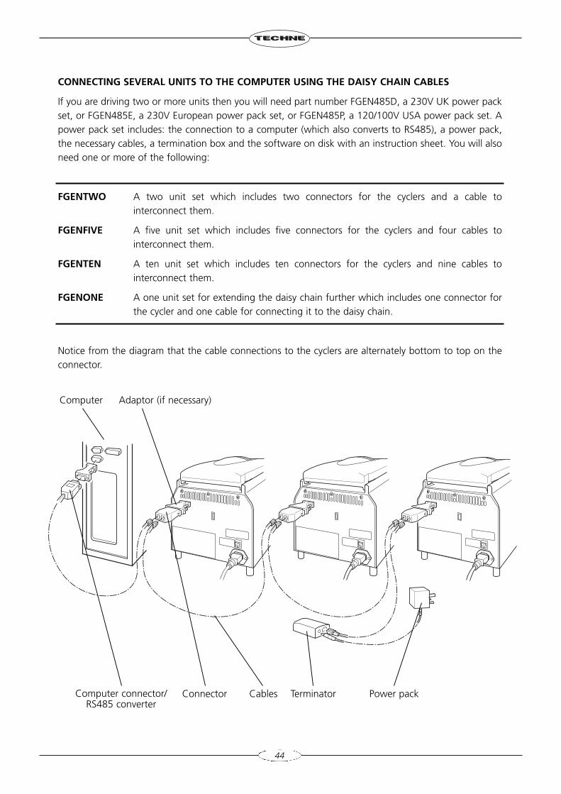
CONNECTING SEVERAL UNITS TO THE COMPUTER USING THE DAISY CHAIN CABLES
If you are driving two or more units then you will need part number FGEN485D, a 230V UK power packset, or FGEN485E, a 230V European power pack set, or FGEN485P, a 120/100V USA power pack set. Apower pack set includes: the connection to a computer (which also converts to RS485), a power pack,the necessary cables, a termination box and the software on disk with an instruction sheet. You will alsoneed one or more of the following:
FGENTWO A two unit set which includes two connectors for the cyclers and a cable tointerconnect them.
FGENFIVE A five unit set which includes five connectors for the cyclers and four cables tointerconnect them.
FGENTEN A ten unit set which includes ten connectors for the cyclers and nine cables tointerconnect them.
FGENONE A one unit set for extending the daisy chain further which includes one connector forthe cycler and one cable for connecting it to the daisy chain.
Notice from the diagram that the cable connections to the cyclers are alternately bottom to top on theconnector.
Computer Adaptor (if necessary)
Connector Terminator Power packCablesComputer connector/RS485 converter
USER MAINTENANCE
CLEANING YOUR TC-4000
Before cleaning your unit, disconnect from the power supply and allow to cool to below 50ºC. Theheating/cooling block, including wells and flat surfaces, should be cleaned regularly to ensure optimumheat transfer to the samples. Always clean the block if there has been a spillage. Use a cloth or cottonbuds dipped in a fresh, 50:50 water/isopropanol solution and make sure that no deposits are left in thewells.
In the case of radioactive spillages the heater block can be removed from the unit for more detailedcleaning. Techne recommends that you use a proprietary cleaning agent and follow the manufacturer'sinstructions. The heating/cooling block is made of aluminium, therefore an agent such as Neutracon(from Decon Labs Ltd.), suitable for nonferrous metals should be used. However, remember that otherparts of the unit are made of ferrous materials and may be damaged by spillage onto them.
The case of the TC-4000 may be cleaned with a cloth dipped in water or ethanol (methanol orformaldehyde can also be used). No part of the case or cover should be immersed in the solvents. Do notuse aggressive solvents such as acetone or abrasive cleaners.
Before using any cleaning or decontamination method except those recommended here, the responsibleperson should check with Techne that the proposed method will not damage the equipment.
45
46
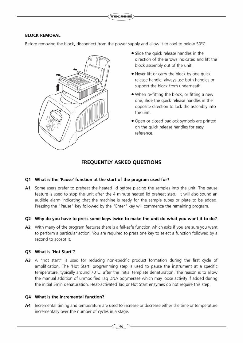
BLOCK REMOVAL
Before removing the block, disconnect from the power supply and allow it to cool to below 50°C.
FREQUENTLY ASKED QUESTIONS
Q1 What is the 'Pause' function at the start of the program used for?
A1 Some users prefer to preheat the heated lid before placing the samples into the unit. The pausefeature is used to stop the unit after the 4 minute heated lid preheat step. It will also sound anaudible alarm indicating that the machine is ready for the sample tubes or plate to be added.Pressing the "Pause" key followed by the "Enter" key will commence the remaining program.
Q2 Why do you have to press some keys twice to make the unit do what you want it to do?
A2 With many of the program features there is a fail-safe function which asks if you are sure you wantto perform a particular action. You are required to press one key to select a function followed by asecond to accept it.
Q3 What is 'Hot Start'?
A3 A "hot start" is used for reducing non-specific product formation during the first cycle ofamplification. The 'Hot Start' programming step is used to pause the instrument at a specifictemperature, typically around 70ºC, after the initial template denaturation. The reason is to allowthe manual addition of unmodified Taq DNA polymerase which may loose activity if added duringthe initial 5min denaturation. Heat-activated Taq or Hot Start enzymes do not require this step.
Q4 What is the incremental function?
A4 Incremental timing and temperature are used to increase or decrease either the time or temperatureincrementally over the number of cycles in a stage.
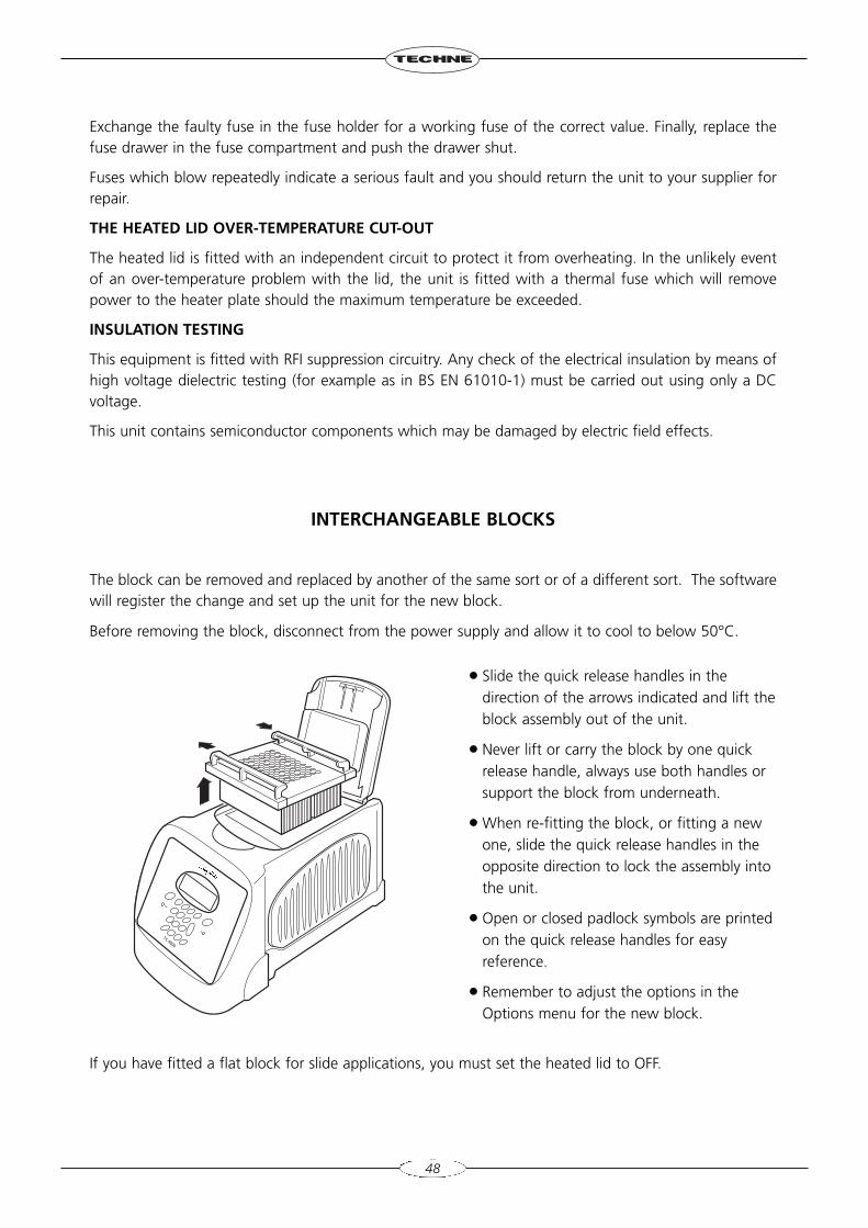
● Slide the quick release handles in thedirection of the arrows indicated and lift theblock assembly out of the unit.
● Never lift or carry the block by one quickrelease handle, always use both handles orsupport the block from underneath.
● When re-fitting the block, or fitting a newone, slide the quick release handles in theopposite direction to lock the assembly intothe unit.
● Open or closed padlock symbols are printedon the quick release handles for easyreference.
47
Incrementation of extension time is used with 'Long PCR' which is when large template fragmentsare to be amplified (e.g. 27kb lambda DNA, 40kb genomic DNA).
Decremental temperature is used for protocols such as 'Touchdown PCR' where one starts with ahigh annealing temperature in the first cycle and gradually decreases the temperature over thenumber of cycles in the stage. This ensures that only the specific product is amplified.
Q5 What is the appropriate pressure of the heated lid?
A5 The lid will need to be adjusted for the height of each different type of consumable used in theunit. Firstly, with the lid in the down position, turn the orange rotating knob anticlockwise until itwill not go any further. Next with the tubes or plate in the unit, lock the lid and turn the knobclockwise until pressure on the tubes or plate is just felt; then rotate another quarter turn. Do notover-tighten.
If you require further technical or applicational assistance please contact Techne at:[email protected].
For servicing information please contact: [email protected].
We are continually striving to improve our thermal cyclers and software. If you have any comments andsuggestions on how we can do things better please send them to us at:[email protected]
ADDITIONAL INFORMATION
Brief fault finding notes and a list of replacement parts are given in this section.
Note that this equipment should only be dismantled by properly trained personnel. Removing the outercover exposes potentially lethal mains voltages. There are no user serviceable parts within this equipment.
FAULT FINDING
Should you have any problems with your TC-4000 which cannot be easily remedied, you should contactyour supplier and return the unit if necessary. Please include details of the fault observed and rememberto return the unit in its original packing. Techne accepts no responsibility for damage to units which arenot properly packed for shipping: if in doubt, contact your supplier, giving the full serial number of theunit and software version number (shown when the unit is first switched on).
FUSES
If neither the power light nor display on the front panel is lit, one of the two fuses may have blown.Check that there is no external cause, such as a faulty plug or lead. Check both fuses and replace thefaulty fuse with a new one of the correct value (fuse values are given on the label next to the power inlet).Note that fuses should only be replaced by a qualified electrician.
The holder for the two fuses is built into the mains input socket. First remove the power cable and thengently prise the fuse drawer open with a flat-bladed screwdriver or similar tool.
Each fuse can be removed by using the screwdriver as a lever.
48
Exchange the faulty fuse in the fuse holder for a working fuse of the correct value. Finally, replace thefuse drawer in the fuse compartment and push the drawer shut.
Fuses which blow repeatedly indicate a serious fault and you should return the unit to your supplier forrepair.
THE HEATED LID OVER-TEMPERATURE CUT-OUT
The heated lid is fitted with an independent circuit to protect it from overheating. In the unlikely eventof an over-temperature problem with the lid, the unit is fitted with a thermal fuse which will removepower to the heater plate should the maximum temperature be exceeded.
INSULATION TESTING
This equipment is fitted with RFI suppression circuitry. Any check of the electrical insulation by means ofhigh voltage dielectric testing (for example as in BS EN 61010-1) must be carried out using only a DCvoltage.
This unit contains semiconductor components which may be damaged by electric field effects.
INTERCHANGEABLE BLOCKS
The block can be removed and replaced by another of the same sort or of a different sort. The softwarewill register the change and set up the unit for the new block.
Before removing the block, disconnect from the power supply and allow it to cool to below 50°C.
If you have fitted a flat block for slide applications, you must set the heated lid to OFF.
● Slide the quick release handles in thedirection of the arrows indicated and lift theblock assembly out of the unit.
● Never lift or carry the block by one quickrelease handle, always use both handles orsupport the block from underneath.
● When re-fitting the block, or fitting a newone, slide the quick release handles in theopposite direction to lock the assembly intothe unit.
● Open or closed padlock symbols are printedon the quick release handles for easyreference.
● Remember to adjust the options in theOptions menu for the new block.
ACCESSORIES
The following accessories can be obtained from Techne or your Techne distributor:
Item No Description QuantityFTC41B5D 60 x 0.5ml micro tubes 1FTC41BHD 96 x 0.2ml micro tubes or 96 well plate 1FTC41BFD 96 x 0.2ml micro tubes or 96 well fully skirted plate 1FTC4B384 384 well block 1FTC41BID Flat plate (in situ) block 1FTUB02TW 0.2ml micro tubes Pack of 1000FTUB05TW 0.5ml micro tubes thin wall Pack of 1000FMIP384 384 well plate Pack of 50
REPLACEMENT PARTS
The following replacement parts can be obtained from Techne or your Techne distributor:
Item No Description Quantity requiredFCABRTUK Mains cable and plug, 230V UK 1FCABRTEU Mains cable and Schuko plug, 230V Europe 1FCABRTUS Mains cable and 3-pin plug, 100V/120V US type 16500342 Fuse T6.3A (230V units) 26008445 Fuse T8A (120/100V units) 26500324 Fuse T10A (100V units) 2
49

Bibby Scientific LtdBeacon Road, Stone, Staffordshire, ST15 0SAUnited KingdomTel: +44 (0)1785 812121 Fax: +44 (0)1785 813748 email: [email protected]
Bibby Scientific France SASZI du Rocher Vert - BP 79,77793 Nemours Cedex, FranceTel: +33 1 64 45 13 13 Fax: +33 1 64 45 13 00 e-mail: [email protected]
Bibby Scientific Italia SrlVia Alcide de Gasperi 56,20077 Riozzo di Cerro al Lambro,Milano, ItaliaTel: +39 (0)2 98230679Fax: +39 (0)2 98230211 e-mail: [email protected]
Techne Inc. 3 Terri Lane, Suite 10, Burlington, NJ, 08016, USAToll free: 800-225-9243Tel: +1 609-589-3560 Fax: +1 609-589-2571email: [email protected]
Bibby Scientific (Asia) LtdRoom 607, Yen Sheng Centre,64 Hoi Yuen Road, Kwun Tong,Kowloon, Hong KongTel: +852 3583 1581Fax: +852 3583 1580e-mail [email protected]


