+ All Categories
Home > Documents > TCC Engineering Catalog - Sawyer/Hanson Innovations - … Conveyor catalog/6 S… · 51 Component...

TCC Engineering Catalog - Sawyer/Hanson Innovations - … Conveyor catalog/6 S… · 51 Component...

Date post: 03-Jul-2018
Category:
Upload: dangnhu
View: 213 times
Download: 0 times
Share this document with a friend
58
50 Components SECTION III COMPONENT SECTION III PAGE Component Selection . . . . . . . . . . . . . . . . . . . . . . . . . . . . . . . . . . . . . . . . . . . . . . . . . . . . . . . . . 51 Conveyor Screws. . . . . . . . . . . . . . . . . . . . . . . . . . . . . . . . . . . . . . . . . . . . . . . . . . . . . . . . . . . . . 53 Coupling Bolts, Internal Collars and Lugs . . . . . . . . . . . . . . . . . . . . . . . . . . . . . . . . . . . . . . . . . . 63 Shafts. . . . . . . . . . . . . . . . . . . . . . . . . . . . . . . . . . . . . . . . . . . . . . . . . . . . . . . . . . . . . . . . . . . . . . 64 Hangers . . . . . . . . . . . . . . . . . . . . . . . . . . . . . . . . . . . . . . . . . . . . . . . . . . . . . . . . . . . . . . . . . . . . 68 Hanger Bearings . . . . . . . . . . . . . . . . . . . . . . . . . . . . . . . . . . . . . . . . . . . . . . . . . . . . . . . . . . . . . 76 Trough Ends . . . . . . . . . . . . . . . . . . . . . . . . . . . . . . . . . . . . . . . . . . . . . . . . . . . . . . . . . . . . . . . . 78 Seals . . . . . . . . . . . . . . . . . . . . . . . . . . . . . . . . . . . . . . . . . . . . . . . . . . . . . . . . . . . . . . . . . . . . . . 85 End Bearings . . . . . . . . . . . . . . . . . . . . . . . . . . . . . . . . . . . . . . . . . . . . . . . . . . . . . . . . . . . . . . . . 88 Thrust Bearings . . . . . . . . . . . . . . . . . . . . . . . . . . . . . . . . . . . . . . . . . . . . . . . . . . . . . . . . . . . . . . 90 Trough . . . . . . . . . . . . . . . . . . . . . . . . . . . . . . . . . . . . . . . . . . . . . . . . . . . . . . . . . . . . . . . . . . . . . 92 Saddles and Feet/Trough End Flanges . . . . . . . . . . . . . . . . . . . . . . . . . . . . . . . . . . . . . . . . . . . . 96 Discharges and Gates . . . . . . . . . . . . . . . . . . . . . . . . . . . . . . . . . . . . . . . . . . . . . . . . . . . . . . . . . 97 Covers . . . . . . . . . . . . . . . . . . . . . . . . . . . . . . . . . . . . . . . . . . . . . . . . . . . . . . . . . . . . . . . . . . . . 103 Cover Accessories . . . . . . . . . . . . . . . . . . . . . . . . . . . . . . . . . . . . . . . . . . . . . . . . . . . . . . . . . . . 105 Shrouds . . . . . . . . . . . . . . . . . . . . . . . . . . . . . . . . . . . . . . . . . . . . . . . . . . . . . . . . . . . 106 SEE PRICE LIST FOR ITEMS CARRIED IN STOCK
Transcript

50

Components

SECTION III

COMPONENT SECTION III PAGE

Component Selection . . . . . . . . . . . . . . . . . . . . . . . . . . . . . . . . . . . . . . . . . . . . . . . . . . . . . . . . . 51

Conveyor Screws. . . . . . . . . . . . . . . . . . . . . . . . . . . . . . . . . . . . . . . . . . . . . . . . . . . . . . . . . . . . . 53

Coupling Bolts, Internal Collars and Lugs . . . . . . . . . . . . . . . . . . . . . . . . . . . . . . . . . . . . . . . . . . 63

Shafts. . . . . . . . . . . . . . . . . . . . . . . . . . . . . . . . . . . . . . . . . . . . . . . . . . . . . . . . . . . . . . . . . . . . . . 64

Hangers . . . . . . . . . . . . . . . . . . . . . . . . . . . . . . . . . . . . . . . . . . . . . . . . . . . . . . . . . . . . . . . . . . . . 68

Hanger Bearings . . . . . . . . . . . . . . . . . . . . . . . . . . . . . . . . . . . . . . . . . . . . . . . . . . . . . . . . . . . . . 76

Trough Ends . . . . . . . . . . . . . . . . . . . . . . . . . . . . . . . . . . . . . . . . . . . . . . . . . . . . . . . . . . . . . . . . 78

Seals . . . . . . . . . . . . . . . . . . . . . . . . . . . . . . . . . . . . . . . . . . . . . . . . . . . . . . . . . . . . . . . . . . . . . . 85

End Bearings . . . . . . . . . . . . . . . . . . . . . . . . . . . . . . . . . . . . . . . . . . . . . . . . . . . . . . . . . . . . . . . . 88

Thrust Bearings . . . . . . . . . . . . . . . . . . . . . . . . . . . . . . . . . . . . . . . . . . . . . . . . . . . . . . . . . . . . . . 90

Trough . . . . . . . . . . . . . . . . . . . . . . . . . . . . . . . . . . . . . . . . . . . . . . . . . . . . . . . . . . . . . . . . . . . . . 92

Saddles and Feet/Trough End Flanges . . . . . . . . . . . . . . . . . . . . . . . . . . . . . . . . . . . . . . . . . . . . 96

Discharges and Gates . . . . . . . . . . . . . . . . . . . . . . . . . . . . . . . . . . . . . . . . . . . . . . . . . . . . . . . . . 97

Covers . . . . . . . . . . . . . . . . . . . . . . . . . . . . . . . . . . . . . . . . . . . . . . . . . . . . . . . . . . . . . . . . . . . . 103

Cover Accessories. . . . . . . . . . . . . . . . . . . . . . . . . . . . . . . . . . . . . . . . . . . . . . . . . . . . . . . . . . . 105

Shrouds . . . . . . . . . . . . . . . . . . . . . . . . . . . . . . . . . . . . . . . . . . . . . . . . . . . . . . . . . . . 106

SEE PRICE LIST FOR ITEMS CARRIEDIN STOCK

51

Component Selection

Required Information

Screw diameterShaft diameterMaterial component groupUnusual material characteristics

Conveyor Screws

Standard length conveyor screws should be used wheneverpossible to reduce the number of hanger bearings required.

The recommended screws listed in the Component SeriesTable are standard helicoid and sectional screw conveyors. Theuse of helicoid or sectional conveyors is largely a matter of indi-vidual preference.

Right hand screw conveyors pull material toward the end whichis being rotated in a clockwise direction. If the rotation isreversed (counterclockwise), the material is pushed away fromthat end.

In left hand screw conveyors, the material flow is opposite tothat of right hand screws, the direction of rotation beingunchanged.

To determine hand of screw see pages 39 and 40.

The material is carried on one face of the conveyor flighting inconveyors which are required to transport material in one direc-tion, therefore, conveyor end lugs are located on the oppositeface to facilitate unimpeded flow of the material. Conveyor sec-tions must be installed in such a manner that all end lugs aretoward the inlet end of the conveyor. Conveyor sections mustnot be turned end for end without reversing the direction of rota-tion, or conversely, the direction of rotation must not be reversedwithout turning the conveyor sections end for end.

Requirements for reversible conveyor screws intended formaterial transport in either direction should be referred to ourEngineering Department.

Flighting should be omitted from the conveyor pipe over the lastdischarge opening to ensure complete discharge of materialwithout carryover.

Continuity of material flow at hanger points is accomplished byopposing adjacent flight ends approximately 180°. (As close to180° as the predrilled holes will allow.)

Conveyor Trough and Tubular HousingStandard trough and housing sections are available in five,six, ten, and 12 foot lengths. Standard five and six foot lengthsshould be used when connecting flanges coincide with dis-charge openings or hanger bearings.

ShaftsThe primary consideration in determining the type and size ofcoupling and drive shafts is whether the shafts selected areadequate to transmit the horsepower required, including anyoverload. Normally, cold-rolled shafts are adequate. However,high-tensile shafts may be required due to torque limitations.Also, stainless steel shafts may be necessary when corrosiveor contaminable materials are to be handled. Conveyorsequipped with non-lubricated hard iron hanger bearingsrequire hardened coupling shafts. Specific shaft size determi-nation is covered in the Torsional Rating Section, page 28.

Shaft Seals

Several conveyor end seal types are available to prevent conta-mination of the conveyed material or to prevent the escape ofmaterial from the system.

Bearings

Hanger Bearing — The purpose of hanger bearings is to pro-vide intermediate support when multiple screw sections areused. Hanger bearings are designed primarily for radial loads.Therefore, adequate clearance should be allowed between thebearings and the conveyor pipe ends to prevent damage by thethrust load which is transmitted through the conveyor pipe.

The hanger bearing recommendations listed in the MaterialCharacteristic Tables are generally adequate for the material tobe handled. Often, however, unusual characteristics of thematerial or the conditions under which the conveyor must oper-ate make it desirable to use special bearing materials.Regarding the use of special bearing materials, consult ourEngineering Department.

End Bearings — Several end bearing types are available, andtheir selection depends on two basic factors: Radial load andthrust load. The relative values of these loads determines endbearing types.

pages 49 - 64 4/7/05 11:29 AM Page 51

52

Component Selection

Radial load is negligible at the conveyor tail shaft. However,drive ends (unless integrated with the conveyor end plate) aresubject to radial loading due to overhung drive loads, such aschain sprockets or shaft-mounted speed reducers. ScrewConveyor Drive Reducers at the drive end will adequately carryboth thrust and radial loads.

Discharge Spouts and Gates

Standard discharge spouts and gates are available for eitherconveyor trough or tubular housing in several designs, operatedeither manually or by remote controls.

In installations where it is possible to overfill the device to whichmaterial is being transported, an additional overflow dischargeopening or overflow relief device should be provided. Consultour Engineering Department for suggested electrical interlockand safety devices to prevent overflow or damage to equip-ment.

It is sometimes found that the material characteristics are suchthat standard component specifications are inadequate. Shouldunusual material characteristics or severe conditions exist, ourEngineering Department should be consulted.

Conveyor Ends

A complete line of conveyor ends are available as standard foreither conveyor trough or tubular housing with a choice of manybearing types and combinations.

Special Applications

More common of the unusual material characteristics whichrequire other than the recommended components are:

Corrosive Materials — Components may be fabricated fromalloys not affected by the material or may be coated with a pro-tective substance.

Contaminable Materials — Require the use of oil impregnat-ed, sealed, or dry type hanger bearings. End shafts should besealed to prevent entrance of contaminants from the outside.Due to the necessity for frequent cleaning conveyor compo-nents should be designed for convenient disassembly.

Abrasive Materials — These materials may be handled inconveyors, troughs, or housings constructed of abrasion resis-tant alloys with hard surfaced screws. Lining of all exposed sur-faces with rubber or special resins also materially reducesabrasive damage.

Interlocking or Matting Materials — Conveying with stan-dard components is sometimes possible by the use of specialfeeding devices at the conveyor inlet.

Hygroscopic Materials — Frequently these materials may behandled successfully in a conveyor which is substantially sealedfrom the exterior atmosphere. In extreme cases it is necessaryto provide jacketed trough or housing with an appropriate circu-lating medium to maintain the material at an elevated tempera-ture. Purging of the conveyor with a suitable dry gas is alsoused in some installations.

Viscous or Sticky Materials — Ribbon flight conveyor screwsare most frequently used for conveying these materialsalthough standard components may be specially coated toimprove the flow of material.

Harmful Vapors or Dusts — These materials may be safelyhandled in dust sealed trough, plain tubular housing, or gasket-ed flanged tubular housing with particular attention to shaft seal-ing. Trough or housing exhaust systems have also beensuccessfully used in some installations.

Blending in Transit — Ribbon, cut flight, paddle, or a combina-tion of these screw types may be designed to produce thedesired degree of blending, aeration or mixing.

Explosive Dusts — The danger of this condition may be mini-mized in most installations by the use of components which arefabricated from non-ferrous materials and proper conveyor seal-ing techniques observed. Exhaust systems are also advisablefor the removal of explosive dusts.

Materials Subject to Packing — This condition requires theuse of aerating devices at the conveyor inlet when materials arepulverulent and a special feeder device when material particlesare large or fibrous.

Materials which are Fluid when Aerated — This conditionmay be used to advantage in some installations by declining theconveyor system toward the discharge end.

Degradable Materials — Some particles that are easily bro-ken or distorted may usually be handled in screw conveyors byreducing the speed and selecting a larger conveyor size suffi-cient to deliver the required volume of material.

Elevated Temperature — Components should be fabricatedfrom high temperature alloys. Should the process be such thatcooling of the material in the conveyor is permissible, jacketedtrough or housing may be used at the inlet end to cool the mate-rial and standard components used after the point where mater-ial temperature has been reduced to a safe degree.

53

Conveyor Screws

Flight pitch is reduced to 2/3diameter. Recommended forinclined or vertical applica-tions. Used in screw feeders.Shorter pitch reduces flush-ing of materials which flu-idize.

STANDARD PITCH, SINGLE FLIGHTConveyor screws with pitchequal to screw diameter areconsidered standard. Theyare suitable for a wholerange of materials in mostconventional applications.

TAPERED, STANDARD PITCH, SINGLEScrew flights increasefrom 2/3 to full diameter.Used in screw feeders toprovide uniform with-drawal of lumpy materials.Generally equivalent toand more economical thanvariable pitch.

SHORT PITCH, SINGLE FLIGHT SINGLE CUT-FLIGHT, STANDARD PITCHScrews are notched at regu-lar intervals at outer edge.Affords mixing action andagitation of material in tran-sit. Useful for moving mate-rials which tend to pack.

HALF PITCH, SINGLE FLIGHT

Similar to short pitchexcept pitch is reduced to1/2 standard pitch. Usefulfor inclined applications,for screw feeders and forhandling extremely fluidmaterials.

Folded flight segments liftand spill the material.Partially retarded flow pro-vides thorough mixingaction. Excellent for heat-ing, cooling or aeratinglight substances.

END DISC ON CONVEYOR SCREW

An end disc is the same diameter as thescrew and is welded flush with the end ofthe pipe shaft and, of course, rotates withthe screw. The end disc helps to keepmaterial away from the trough seal.

Price on Application

SINGLE FLIGHT RIBBON

Excellent for conveyingsticky or viscous materi-als. Open space betweenflighting and pipe eliminatecollection and build-upof material.

VARIABLE PITCH, SINGLE FLIGHTFlights have increasingpitch and are used in screwfeeders to provide uniformwithdrawal of fine, freeflowing materials over thefull length of the inlet open-ing. Price on Application

STANDARD PITCH WITH PADDLESAdjustable paddles posi-tioned between screwflights opposed flow toprovide gentle but thor-ough mixing action.

DOUBLE FLIGHT, STANDARD PITCHDouble flight, standardpitch screws providesmooth regular materialflow and uniform move-ment of certain types ormaterials.

PADDLE

Adjustable paddles providecomplete mixing action,and controlled materialflow.

Price on Application

Price on Application

D

CUT & FOLDED FLIGHT, STANDARD PITCH

D

Note: Other special screw types also available. Consult factory for details.

54

4 1 4H206 11⁄4 9-101⁄2 1⁄161⁄8 3⁄16

3⁄321⁄2 1⁄4 1.005 1.016 1⁄2 2 13⁄32

6 11⁄2 6H304 2 9-10 1⁄163⁄16

1⁄8 1⁄161⁄2 1⁄4 1.505 1.516 7⁄8 3 17⁄32

6 11⁄2 6H308 2 9-10 1⁄163⁄16

1⁄4 1⁄8 3⁄4 1⁄4 1.505 1.516 7⁄8 3 17⁄32

6 11⁄2 6H312 2 9-10 1⁄163⁄16

3⁄8 3⁄163⁄4 1⁄4 1.505 1.516 7⁄8 3 17⁄32

9 11⁄2 9H306 2 9-10 1⁄163⁄16

3⁄163⁄32

3⁄4 1⁄4 1.505 1.516 7⁄8 3 17⁄32

9 11⁄2 9H312 2 9-10 1⁄163⁄16

3⁄8 3⁄163⁄4 1⁄4 1.505 1.516 7⁄8 3 17⁄32

9 2 9H406 21⁄2 9-10 1⁄163⁄16

3⁄163⁄32

3⁄4 1⁄4 2.005 2.016 7⁄8 3 21⁄32

9 2 9H412 21⁄2 9-10 1⁄161⁄4 3⁄8 3⁄16

3⁄4 1⁄4 2.005 2.016 7⁄8 3 21⁄32

9 2 9H414 21⁄2 9-10 1⁄161⁄4 7⁄16

7⁄323⁄4 1⁄4 2.005 2.016 7⁄8 3 21⁄32

10 11⁄2 10H306 2 9-10 1⁄163⁄16

3⁄163⁄32

3⁄4 1⁄4 1.505 1.516 7⁄8 3 17⁄32

10 2 10H412 21⁄2 9-10 1⁄161⁄4 3⁄8 3⁄16

3⁄4 1⁄4 2.005 2.016 7⁄8 3 21⁄32

12 2 12H408 21⁄2 11-10 1⁄8 5⁄161⁄4 1⁄8 1 1⁄4 2.005 2.016 7⁄8 3 21⁄32

12 2 12H412 21⁄2 11-10 1⁄8 5⁄163⁄8 3⁄16 1 1⁄4 2.005 2.016 7⁄8 3 21⁄32

12 27⁄16 12H508 3 11-9 1⁄8 5⁄161⁄4 1⁄8 1 1⁄4 2.443 2.458 15⁄16 3 21⁄32

12 27⁄16 12H512 3 11-9 1⁄8 5⁄163⁄8 3⁄16 1 1⁄4 2.443 2.458 15⁄16 3 21⁄32

12 3 12H614 31⁄2 11-9 1⁄8 3⁄8 7⁄167⁄32 1 1⁄4 3.005 3.025 1 3 25⁄32

14 27⁄16 14H508 3 11-9 1⁄8 5⁄161⁄4 1⁄8 1 1⁄4 2.443 2.458 15⁄16 3 21⁄32

14 3 14H614 31⁄2 11-9 1⁄8 3⁄8 7⁄167⁄32 1 1⁄4 3.005 3.025 1 3 25⁄32

16 3 16H610 31⁄2 11-9 1⁄8 3⁄8 5⁄165⁄32 11⁄2 1⁄4 3.005 3.025 1 3 25⁄32

16 3 16H614 4 11-9 1⁄8 3⁄8 7⁄167⁄32 11⁄2 1⁄4 3.005 3.025 1 3 25⁄32

CEMAStandards

Listed ScrewDiameter

andPitch

CouplingDiameter

PipeSize

Schedule40

LengthFeetand

InchesPlus PlusMinus Minus Minimum Maximum

InnerEdge

OuterEdge

SizeDesignation

Spacing1st Bolt

Hole

Centers2nd Bolt

Hole

NominalBoltHoleSize

A B C D F G H

DiameterTolerance

PitchTolerance

Thickness Bushing BoreInside Diameter

4 13⁄8 1 5⁄8

6 2 11⁄2 7⁄8

9 3 21⁄8 11⁄2

10 33⁄8 21⁄4 13⁄4

12 4 23⁄4 2

14 45⁄8 31⁄8 21⁄2

16 51⁄4 31⁄2 3

18 6 37⁄8 33⁄8

20 65⁄8 41⁄4 37⁄8

24 77⁄8 47⁄8 47⁄8

ScrewDiameter A B C

NOTE: All dimensions in inches.

Cut Flight/Cut & Folded Flight Conveyors

Depth of cut “C” is one half the flight width for normalmaximum pipe size. Lengths “A” and “B” are calcu-lated from the developed O.D. for standard pitch.

ADiametertolerance

BThicknessat edges

CPitch

tolerance Flighting fitted snug topipe with intermediate welds

End lugs used on all sizesexcept 4″ dia. conveyor

Length

Carrying Side

Omit First Two Cuts

5 CutsPer Pitch

Carrying Side

Omit FirstTwo Cuts

5 Cuts PerPitch

Helicoid Screw Conveyors

+ 0– 1⁄16″

F GH — Bolt hole

DBore

App

roxi

mat

ely

5E

qual

Spa

ces

Right Angle Bend

Ben

d

Line

Omit FirstTwo Cuts

Omit First Two Cuts

55

CEMA Standards

6 11⁄2 6S312 2 9-10 1⁄163⁄16

3⁄163⁄8 1⁄4 1.505 1.516 7⁄8 3 17⁄32

11⁄2 9S312 2 9-10 1⁄163⁄16

3⁄161⁄2 1⁄4 1.505 1.516 7⁄8 3 17⁄32

92 9S412 21⁄2 9-10 1⁄16

3⁄163⁄16

1⁄2 1⁄4 2.005 2.016 7⁄8 3 21⁄32

2 9S416 21⁄2 9-10 1⁄161⁄4 1⁄4 1⁄2 1⁄4 2.005 2.016 7⁄8 3 21⁄32

10 2 10S412 21⁄2 9-10 1⁄163⁄16

3⁄161⁄2 1⁄4 2.005 2.016 7⁄8 3 21⁄32

2 12S412 21⁄2 11-10 1⁄8 5⁄163⁄16

3⁄4 1⁄4 2.005 2.016 7⁄8 3 21⁄32

27⁄16 12S512 3 11-9 1⁄8 5⁄163⁄16

3⁄4 1⁄4 2.443 2.458 15⁄16 3 21⁄32

12 27⁄16 12S516 3 11-9 1⁄8 5⁄161⁄4 3⁄4 1⁄4 2.443 2.458 15⁄16 3 21⁄32

3 12S616 31⁄2 11-9 1⁄8 5⁄161⁄4 3⁄4 1⁄4 3.005 3.025 1 3 25⁄32

3 12S624 31⁄2 11-9 1⁄8 3⁄8 3⁄8 3⁄4 1⁄4 3.005 3.025 1 3 25⁄32

27⁄16 14S512 3 11-9 1⁄8 5⁄163⁄16

3⁄4 1⁄4 2.443 2.458 15⁄16 3 21⁄32

14 3 14S616 31⁄2 11-9 1⁄8 5⁄161⁄4 3⁄4 1⁄4 3.005 3.025 1 3 25⁄32

3 14S624 31⁄2 11-9 1⁄8 3⁄8 3⁄8 3⁄4 1⁄4 3.005 3.025 1 3 25⁄32

3 16S612 31⁄2 11-9 1⁄8 3⁄8 3⁄163⁄4 1⁄4 3.005 3.025 1 3 25⁄32

163 16S616 31⁄2 11-9 1⁄8 3⁄8 1⁄4 3⁄4 1⁄4 3.005 3.025 1 3 25⁄32

3 16S624 31⁄2 11-9 1⁄8 3⁄8 3⁄8 3⁄4 1⁄4 3.005 3.025 1 3 25⁄32

3 16S632 31⁄2 11-9 1⁄8 1⁄2 1⁄2 3⁄4 1⁄4 3.005 3.025 1 3 25⁄32

3 18S612 31⁄2 11-9 3⁄163⁄8 3⁄16

3⁄4 1⁄2 3.005 3.025 1 3 25⁄32

18 3 18S616 31⁄2 11-9 3⁄163⁄8 1⁄4 3⁄4 1⁄2 3.005 3.025 1 3 25⁄32

3 18S624 31⁄2 11-9 3⁄163⁄8 3⁄8 3⁄4 1⁄2 3.005 3.025 1 3 25⁄32

3 18S632 31⁄2 11-9 3⁄161⁄2 1⁄2 3⁄4 1⁄2 3.005 3.025 1 3 25⁄32

3 20S612 31⁄2 11-9 3⁄163⁄8 3⁄16

7⁄8 1⁄2 3.005 3.025 1 3 25⁄32

20 3 20S616 31⁄2 11-9 3⁄163⁄8 1⁄4 7⁄8 1⁄2 3.005 3.025 1 3 25⁄32

3 20S624 31⁄2 11-9 3⁄163⁄8 3⁄8 7⁄8 1⁄2 3.005 3.025 1 3 25⁄32

37⁄16 24S712 4 11-8 3⁄163⁄8 3⁄16

7⁄8 1⁄2 3.443 3.467 11⁄2 4 29⁄32

24 37⁄16 24S716 4 11-8 3⁄163⁄8 1⁄4 7⁄8 1⁄2 3.443 3.467 11⁄2 4 29⁄32

37⁄16 24S724 4 11-8 3⁄163⁄8 3⁄8 7⁄8 1⁄2 3.443 3.467 11⁄2 4 29⁄32

37⁄16 24S732 4 11-8 3⁄161⁄2 1⁄2 7⁄8 1⁄2 3.443 3.467 11⁄2 4 29⁄32

Listed ScrewDiameter

andPitch

Cplng.Dia.

PipeSize

Schedule40

LengthFeetand

InchesPlus PlusMinus Minus Minimum Maximum

SizeDesignation

Spacing1st Bolt

Hole

Centers2nd Bolt

Hole

NominalBoltHoleSize

A B C D F G H

DiameterTolerance

PitchToleranceFlight

Thickness

Bushing BoreInside Diameter

Sectional Screw Conveyors

NOTE: All dimensions in inches.

ADiametertolerance

BThicknessof Butt WeldedFlight

CPitch

tolerance Flighting fitted snug topipe with intermediate welds

End lugs on 6" through 16"sizes. On 18", 20" and 24",end welds or end lugs usedaccording to manufacturer ’sstandards.

Length

F GH — Bolt hole

DBore

+ 0– 1⁄16"

56

Conveyor Screws

4 4H206 4X 1 11⁄4 3⁄163⁄32

6 6H304 6 Standard 11⁄2 2 1⁄8 1⁄16

6H308 6 X 11⁄2 2 1⁄4 1⁄8 6S309 11⁄2 2 10 ga.6H312 6 XX 11⁄2 2 3⁄8 3⁄16 6S312 11⁄2 2 3⁄16 in.

9 9H306 9 Standard 11⁄2 2 3⁄163⁄32 9S307 11⁄2 2 12 ga.

9H406 9 Special 2 21⁄2 3⁄163⁄32 9S407 2 21⁄2 12 ga.

9H312 9 X 11⁄2 2 3⁄8 3⁄16 9S312 11⁄2 2 3⁄16 in.9H412 9 XX 2 21⁄2 3⁄8 3⁄16 9S412 2 21⁄2 3⁄16 in.9H414 — 2 21⁄2 7⁄16

7⁄32 9S416 2 21⁄2 1⁄4 in.10 10H306 10 Standard 11⁄2 2 3⁄16

3⁄32 10S309 11⁄2 2 10 ga.10H412 10 XX 2 21⁄2 3⁄8 3⁄16 10S412 2 21⁄2 3⁄16 in.

12 12H408 12 Standard 2 21⁄2 1⁄4 1⁄8 12S409 2 21⁄2 10 ga.12H508 12 Special 27⁄16 3 1⁄4 1⁄8 12S509 27⁄16 3 10 ga.12H412 12 X 2 21⁄2 3⁄8 3⁄16 12S412 2 21⁄2 3⁄16 in.12H512 12 XX 27⁄16 3 3⁄8 3⁄16 12S512 27⁄16 3 3⁄16 in.12H614 — 3 31⁄2 7⁄16

7⁄32 12S616 3 31⁄2 1⁄4 in.14 14H508 14 Standard 27⁄16 3 1⁄4 1⁄8 14S509 27⁄16 3 10 ga.

14H614 14 XX 3 31⁄2 7⁄167⁄32 14S616 3 31⁄2 1⁄4 in.

16 16H610 16 Standard 3 31⁄2 5⁄165⁄32 16S609 3 31⁄2 10 ga.

16H614 — 3 4 7⁄167⁄32 16S616 3 31⁄2 1⁄4 in.

Helicoid Flight Sectional Flight

ConveyorScrewSize

Designations

CouplingDiameter, Inches

NominalInside

Diameterof Pipe,Inches

Thicknessof Flight

ConveyorScrewSize

Designations

FormerDesignation

CouplingDiameter, Inches

NominalInside

Diameterof Pipe,Inches

Thickness ofFlight, Inches

ScrewDiameter,

InchesInnerEdge

OuterEdge

s Size designation: Examples: 12H412 and 12S412.12 = screw diameter in inchesH = helicoid flightS = sectional flight4 = 2 times 2″ coupling diameter

12 = thickness of flight at periphery in increments of 1⁄64″

Helicoid Flight Sectional Flight

Helicoid flights are formed in a special rolling machineby forming a steel strip into a continuous one-piece helix of thedesired diameter, pitch and thickness to fit conveyor screwpipes. The helicoid flight is tapered in cross section, with thethickness at the inner edge approximately twice the thicknessof the outer edge.

Sectional flights are individual flights or turns blankedfrom steel plates and formed into a spiral or helix of thedesired diameter and pitch to fit conveyor screw pipes. Theflights are butt welded together to form a continuous conveyorscrew. Modifications can be furnished, such as, fabricationfrom various metals, different flight thicknesses, other diame-ters and pitches. The buttweld flight is the same thickness inthe full cross section.

Key to Conveyor Size Designation

The letter “H” indicates screw conveyor with helicoid flighting. The figures to the left of the letters indicate the nominal outside diam-eter of the conveyor in inches. The first figure following the letters is twice the diameter of the couplings in inches. The last two fig-ures indicate the nominal thickness of flighting at the outer edge in 1⁄64″. Thus conveyor 12H408 indicates 12″ diameter helicoidconveyor for 2″ couplings with flighting 8⁄64″ or 1⁄8″ thickness at outer edge. Hand of conveyor is indicated by “R” or “L” following thedesignation.

Comparison Table • helicoid flight and sectional flight conveyor screws

57

Conveyor Screws(Helicoid)

Helicoid Conveyor Screw Flighting

4 1 4H206–* 4HF206–* 11⁄4 15⁄8 3⁄163⁄32 11⁄2 9-101⁄2 40 4 16 1.3

6 11⁄2 6H304–* 6HF304–* 2 23⁄8 1⁄8 1⁄16 2 9-10 52 5 14 1.4

11⁄2 6H308–* 6HF308–* 2 23⁄8 1⁄4 1⁄8 2 9-10 62 6 28 2.8

11⁄2 6H312–* 6HF312–* 2 23⁄8 3⁄8 3⁄16 2 9-10 72 7 42 4.3

9 11⁄2 9H306–* 9HF306–* 2 23⁄8 3⁄163⁄32 2 9-10 70 7 31 3.2

11⁄2 9H312–* 9HF312–* 2 23⁄8 3⁄8 3⁄16 2 9-10 101 10 65 6.1

2 9H406–* 9HF406–* 21⁄2 27⁄8 3⁄163⁄32 2 9-10 91 9 30 3.0

2 9H412–* 9HF412–* 21⁄2 27⁄8 3⁄8 3⁄16 2 9-10 121 12 60 6.6

2 9H414–* 9HF414–* 21⁄2 27⁄8 7⁄167⁄32 2 9-10 131 13 70 6.3

10 11⁄2 10H306–* 10HF306–* 2 23⁄8 3⁄163⁄32 2 9-10 81 8 48 4.9

2 10H412–* 10HF412–* 21⁄2 27⁄8 3⁄8 3⁄16 2 9-10 130 13 76 7.7

12 2 12H408–* 12HF408–* 21⁄2 27⁄8 1⁄4 1⁄8 2 11-10 140 12 67 5.7

2 12H412–* 12HF412–* 21⁄2 27⁄8 3⁄8 3⁄16 2 11-10 180 15 102 8.6

27⁄16 12H508–* 12HF508–* 3 31⁄2 1⁄4 1⁄8 3 11-9 168 14 64 5.4

27⁄16 12H512–* 12HF512–* 3 31⁄2 3⁄8 3⁄16 3 11-9 198 17 96 8.2

3 12H614–* 12HF614–* 31⁄2 4 7⁄167⁄32 3 11-9 220 18 112 9.3

14 27⁄16 14H508–* 14HF508–* 3 31⁄2 1⁄4 1⁄8 3 11-9 170 14 84 7.1

3 14H614–* 14HF614–* 31⁄2 4 7⁄167⁄32 3 11-9 254 22 132 11.2

16 3 16H610–* 16HF610–* 31⁄2 4 5⁄165⁄32 3 11-9 228 19 120 10.0

s 3 16H614–* 16HF614–* 4 41⁄2 7⁄167⁄32 3 11-9 285 24 154 11.7

18 s 3 18H610–* 18HF610–* 31⁄2 4 5⁄165⁄32 3 11-9 282 24 167 13.9

A

ScrewDiameter

CouplingDiameter

CouplingBearingLength

StandardLength

Feet-Inches

SizePart No.ConveyorMounted

SizePart No.Flighting

Only

B DPipe Size

FlightThickness

H Average Weight

Complete Screw Flighting Only

F

Inside OutsideInside Outside

G StandardLength

PerFoot

StandardLength

PerFoot

–* R For Right Hand–* L For Left Hand

s Offered only in full pitch helicoid flighting.

Length Length

58

Conveyor Screws(Sectional)

6 11⁄2 6S312–* 6SF312–* 2 23⁄8 3⁄16 2 9-10 75 7.5 1.7 2.0

11⁄2 6S316–* 6SF316–* 2 23⁄8 1⁄4 2 9-10 90 8.0 2.2 2.0

9 11⁄2 9S312–* 9SF312–* 2 23⁄8 3⁄16 2 9-10 95 9.5 4.3 1.33

11⁄2 9S316–* 9SF316–* 2 23⁄8 1⁄4 2 9-10 130 13.0 5.5 1.33

11⁄2 9S324–* 9SF324–* 2 23⁄8 3⁄8 2 9-10 160 16.0 7.9 1.33

2 9S412–* 9SF412–* 21⁄2 27⁄8 3⁄16 2 9-10 115 11.5 4.3 1.33

2 9S416–* 9SF416–* 21⁄2 27⁄8 1⁄4 2 9-10 130 13.0 5.5 1.33

2 9S424–* 9SF424–* 21⁄2 27⁄8 3⁄8 2 9-10 160 16.0 7.9 1.33

10 11⁄2 10S312–* 10SF312–* 2 23⁄8 3⁄16 2 9-10 120 12.0 5.0 1.2

11⁄2 10S316–* 10SF316–* 2 23⁄8 1⁄4 2 9-10 135 13.5 6.7 1.2

11⁄2 10S324–* 10SF324–* 2 23⁄8 3⁄8 2 9-10 165 16.5 8.7 1.2

2 10S412–* 10SF412–* 21⁄2 27⁄8 3⁄16 2 9-10 120 12.0 5.0 1.2

2 10S416–* 10SF416–* 21⁄2 27⁄8 1⁄4 2 9-10 135 13.5 6.7 1.2

2 10S424–* 10SF424–* 21⁄2 27⁄8 3⁄8 2 9-10 165 16.5 8.7 1.2

12 2 12S412–* 12SF412–* 21⁄2 27⁄8 3⁄16 2 11-10 156 13.0 7.2 1.0

2 12S416–* 12SF416–* 21⁄2 27⁄8 1⁄4 2 11-10 204 17.0 9.7 1.0

2 12S424–* 12SF424–* 21⁄2 27⁄8 3⁄8 2 11-10 268 22.3 12.7 1.0

27⁄16 12S509–* 12SF509–* 3 31⁄2 10 Ga. 3 11-9 160 14.0 5.7 1.0

27⁄16 12S512–* 12SF512–* 3 31⁄2 3⁄16 3 11-9 178 14.8 7.2 1.0

27⁄16 12S516–* 12SF516–* 3 31⁄2 1⁄4 3 11-9 210 17.5 9.7 1.0

27⁄16 12S524–* 12SF524–* 3 31⁄2 3⁄8 3 11-9 274 22.5 12.7 1.0

3 12S612–* 12SF612–* 31⁄2 4 3⁄16 3 11-9 198 16.5 7.2 1.0

3 12S616–* 12SF616–* 31⁄2 4 1⁄4 3 11-9 216 18.0 9.7 1.0

3 12S624–* 12SF624–* 31⁄2 4 3⁄8 3 11-9 280 24.0 12.7 1.0

Sectional Conveyor Screw Flight

A

ScrewDiameter

CouplingDiameter

CouplingBearingLength

StandardLength

Feet-Inches

SizePart No.MountedConveyor

SizePart No.Flighting

Only

B Pipe Size

FlightThickness

HF Average Weight

D

Inside Outside

StandardLength

PerFoot

FlightEach

Approx.Flights

Per Foot

–* R For Right Hand–* L For Left Hand

Length

59

Conveyor Screws(Sectional)

14 27⁄16 14S512–* 14SF512–* 3 31⁄2 3⁄16 3 11-9 214 18.0 9.9 .86

27⁄16 14S516–* 14SF516–* 3 31⁄2 1⁄4 3 11-9 240 20.0 13.2 .86

27⁄16 14S524–* 14SF524–* 3 31⁄2 3⁄8 3 11-9 330 27.5 19.8 .86

3 14S612–* 14SF612–* 31⁄2 4 3⁄16 3 11-9 222 19.0 9.9 .86

3 14S616–* 14SF616–* 31⁄2 4 1⁄4 3 11-9 246 21.0 13.2 .86

3 14S624–* 14SF624–* 31⁄2 4 3⁄8 3 11-9 342 29.0 19.8 .86

16 3 16S612–* 16SF612–* 31⁄2 4 3⁄16 3 11-9 234 20.0 14.0 .75

3 16S616–* 16SF616–* 31⁄2 4 1⁄4 3 11-9 282 24.0 18.0 .75

3 16S624–* 16SF624–* 31⁄2 4 3⁄8 3 11-9 365 31.0 25.5 .75

3 16S632–* 16SF632–* 31⁄2 4 1⁄2 3 11-9 402 33.5 36.0 .75

18 3 18S612–* 18SF612–* 31⁄2 4 3⁄16 3 11-9 246 21.0 18.0 .67

3 18S616–* 18SF616–* 31⁄2 4 1⁄4 3 11-9 294 25.0 24.0 .67

3 18S624–* 18SF624–* 31⁄2 4 3⁄8 3 11-9 425 36.0 34.5 .67

3 18S632–* 18SF632–* 31⁄2 4 1⁄2 3 11-9 530 44.0 46.0 .67

37⁄16 18S712–* 18SF712–* 4 41⁄2 3⁄16 4 11-8 293 24.4 18.0 .67

37⁄16 18S716–* 18SF716–* 4 41⁄2 1⁄4 4 11-8 345 28.8 24.0 .67

37⁄16 18S724–* 18SF724–* 4 41⁄2 3⁄8 4 11-8 470 39.2 34.5 .67

37⁄16 18S732–* 18SF732–* 4 41⁄2 1⁄2 4 11-8 570 47.5 46.0 .67

20 3 20S612–* 20SF612–* 31⁄2 4 3⁄16 3 11-9 300 26.0 20.0 .60

3 20S616–* 20SF616–* 31⁄2 4 1⁄4 3 11-9 360 31.0 28.0 .60

3 20S624–* 20SF624–* 31⁄2 4 3⁄8 3 11-9 410 33.4 40.0 .60

3 20S632–* 20SF632–* 31⁄2 4 1⁄2 3 11-9 506 42.2 56.0 .60

37⁄16 20S712–* 20SF712–* 4 41⁄2 3⁄16 4 11-8 310 27.0 20.0 .60

37⁄16 20S716–* 20SF716–* 4 41⁄2 1⁄4 4 11-8 370 32.0 28.0 .60

37⁄16 20S724–* 20SF724–* 4 41⁄2 3⁄8 4 11-8 475 40.0 40.0 .60

37⁄16 20S732–* 20SF732–* 4 41⁄2 1⁄2 4 11-8 525 45.0 56.0 .60

24 37⁄16 24S712–* 24SF712–* 4 41⁄2 3⁄16 4 11-8 440 37.0 32.0 .50

37⁄16 24S716–* 24SF716–* 4 41⁄2 1⁄4 4 11-8 510 43.0 42.0 .50

37⁄16 24S724–* 24SF724–* 4 41⁄2 3⁄8 4 11-8 595 50.0 63.0 .50

37⁄16 24S732–* 24SF732–* 4 41⁄2 1⁄2 4 11-8 690 60.0 84.0 .50

A

ScrewDiameter

CouplingDiameter

CouplingBearingLength

StandardLength

Feet-Inches

SizePart No.MountedConveyor

SizePart No.Flighting

Only

B Pipe Size

FlightThickness

HF Average Weight

D

Inside Outside

StandardLength

PerFoot

FlightEach

Approx.Flights

Per Foot

–* R For Right Hand–* L For Left Hand

Sectional Conveyor Screw Flight

Length

60

Conveyor Screws(Ribbon)

6 11⁄2 6R312–* 2 23⁄8 3⁄16 1 2 9-10 65 6.5

9 11⁄2 9R316–* 2 23⁄8 1⁄4 11⁄2 2 9-10 100 10

10 11⁄2 10R316–* 2 23⁄8 1⁄4 11⁄2 2 9-10 110 11

12 2 12R416–* 21⁄2 27⁄8 1⁄4 2 2 11-10 180 15

2 12R424–* 21⁄2 27⁄8 3⁄8 21⁄2 2 11-10 216 19

27⁄16 12R524–* 3 31⁄2 3⁄8 21⁄2 3 11-9 240 21

14 27⁄16 14R516–* 3 31⁄2 1⁄4 21⁄2 3 11-9 228 19

27⁄16 14R524–* 3 31⁄2 3⁄8 21⁄2 3 11-9 264 22

3 14R624–* 31⁄2 4 3⁄8 21⁄2 3 11-9 288 25

16 3 16R616–* 31⁄2 4 1⁄4 21⁄2 3 11-9 276 24

3 16R624–* 31⁄2 4 3⁄8 21⁄2 3 11-9 324 28

18 3 18R624–* 31⁄2 4 3⁄8 3 3 11-9 384 33

20 37⁄16 20R724–* 4 41⁄2 3⁄8 3 4 11-8 408 35

24 37⁄16 24R724–* 4 41⁄2 3⁄8 3 4 11-8 424 36

A

ScrewDiameter

CouplingDiameter

HCouplingBearingLength

StandardLength

Feet-Inches

SizePart No.MountedConveyor

BPipe Size

FThickness

GWidth

Flight Size Weight

Complete Screw

Inside OutsidePerFoot

StandardLength

Post Integral (Int)Leg

Ribbon Conveyor Screw

Ribbon flight conveyor screws consist of sec-tional flights, buttwelded together to form a con-tinuous helix. Flights are secured to the pipe bysupporting legs. Both ends of the pipe are pre-pared with internal collars and drilling to acceptcouplings, drive shafts, and end shafts. They areused to convey sticky, gummy, or viscous sub-stances, or where the material tends to adhereto flighting and pipe.

–* R For Right Hand–* L For Left Hand

Length

61

ConveyorScrews

6 6HQ304–* 11⁄2 9′-10 3QDC2 2 23⁄8 1⁄8 1⁄16 2 52 5

6HQ308–* 1⁄4 1⁄8 2 62 6

6HQ312–* 3⁄8 3⁄16 2 72 7

9 9HQ306–* 11⁄2 9′-10 3QDC2 2 23⁄8 3⁄163⁄32 2 70 7

9HQ312–* 3⁄8 3⁄16 2 101 10

9HQ406–* 2 9′-10 3⁄163⁄32 2 91 9

9HQ412–* 4QDC25 21⁄2 27⁄8 3⁄8 3⁄16 2 121 12

9HQ414–* 7⁄167⁄32 2 131 13

10 10HQ306–* 11⁄2 9′-10 3QDC2 2 23⁄8 3⁄163⁄32 2 81 8

10HQ412–* 2 9′-10 4QDC25 21⁄2 27⁄8 3⁄8 3⁄16 2 130 13

12 12HQ408–* 2 11′-10 4QDC25 21⁄2 27⁄8 1⁄4 1⁄8 2 140 12

12HQ412–* 3⁄8 3⁄16 2 180 15

12HQ508–* 27⁄16 11′-9 5QDC3 3 31⁄2 1⁄4 1⁄8 3 168 14

12HQ512–* 3⁄8 3⁄16 3 198 17

12HQ614–* 3 11′-9 6QDC35 31⁄2 4 7⁄167⁄32 3 220 18

14 14HQ508–* 27⁄16 11′-9 5QDC3 3 31⁄2 1⁄4 1⁄8 3 170 14

14HQ614–* 3 11′-9 6QDC35 31⁄2 4 7⁄167⁄32 3 254 22

16 16HQ610–* 3 11′-9 6QDC35 31⁄2 4 5⁄165⁄32 3 228 19

16HQ614–* 3 11′-9 6QDC4 4 41⁄2 7⁄167⁄32 3 270 23

18 18HQ610–* 3 11′-9 6QDC35 31⁄2 4 5⁄165⁄32 3 282 24

A

NominalConveyorDiameter

CouplingDiameter

CapPart

Number

CouplingBearingLength

FlightThicknessSize

Part No.MountedConveyor

B C D HStandard-LengthFeet-Inches

End to Endof Pipe

Pipe Size

Inside Outside FInside

GOutside

AverageWeight

PerFoot

StandardLength

Quick Detachable (QD) Helicoid Conveyor

Q.D. — Quick Detachable conveyor screws are designed for convenient removal from the conveyor assembly. Each section ofscrew has a Q.D. cap at one end of the pipe. By removing this cap, a conveyor screw section can quickly and easily be removedand returned to the conveyor assembly without disturbing the other screw sections. Quick Detachable conveyor can be furnishedboth in helicoid and buttweld construction.

R.H. Shown

Note: Q.D. caps are not recommended on the drive shaft end.–* R For Right Hand–* L For Left Hand

pages 49 - 64 4/7/05 11:29 AM Page 61

62

ConveyorScrews

6 6SQ307–* 11⁄2 9′-10 3QDC2 2 23⁄8 12 2 62 6.2 6SQ309–* 10 65 6.5 6SQ312–* 3⁄16 2 75 7.5 6SQ316–* 1⁄4 90 8.0

9 9SQ307–* 11⁄2 9′-10 3QDC2 2 23⁄8 12 73 7.3 9SQ309–* 10 80 8.0 9SQ312–* 3⁄16 2 95 9.5 9SQ316–* 1⁄4 120 13

9SQ407–* 2 9′-10 4QDC25 21⁄2 27⁄8 12 90 9 9SQ409–* 10 100 10 9SQ412–* 3⁄16 2 115 11.5 9SQ416–* 1⁄4 130 13.0 9SQ424–* 3⁄8 160 16

10SQ309–* 11⁄2 9′-10 3QDC2 2 23⁄8 10 2 85 8.5

10 10SQ412–* 2 9′-10 4QDC25 21⁄2 27⁄8 3⁄16 2 120 12.0 10SQ416–* 1⁄4 135 13.5

12 12SQ409–* 2 11′-10 4QDC25 21⁄2 27⁄8 10 2 140 12.0 12SQ412–* 3⁄16 156 13.0 12SQ416–* 1⁄4 204 17

12SQ509–* 27⁄16 11′-9 5QDC3 3 31⁄2 10 3 160 14 12SQ512–* 3⁄16 178 15

12SQ612–* 3 11′-9 6QDC35 31⁄2 4 3⁄16 191 16.5 12SQ616–* 1⁄4 3 216 18.0 12SQ624–* 3⁄8 280 24

14 14SQ509–* 27⁄16 11′-9 5QDC3 3 31⁄2 10 3 185 16 14SQ512–* 3⁄16 214 18

14SQ612–* 3 11′-9 6QDC35 31⁄2 4 3⁄16 3 222 19 14SQ616–* 1⁄4 246 21 14SQ624–* 3⁄8 342 29

16 16SQ609–* 3 11′-9 6QDC35 31⁄2 4 10 3 210 18 16SQ612–* 3⁄16 234 20 16SQ616–* 1⁄4 282 24 16SQ624–* 3⁄8 365 31

18 18SQ612–* 3 11′-9 6QDC35 31⁄2 4 3⁄16 3 246 21 18SQ616–* 1⁄4 294 25 18SQ624–* 3⁄8 425 36

20 20SQ612–* 3 11′-9 6QDC35 31⁄2 4 3⁄16 3 300 26 20SQ616–* 1⁄4 360 31

20SQ724–* 37⁄16 11′-8 7QDC4 4 41⁄2 3⁄8 4 475 40

24 24SQ712–* 37⁄16 11′-8 7QDC4 4 41⁄2 3⁄16 4 410 37 24SQ716–* 1⁄4 510 43 24SQ724–* 3⁄8 595 50

A

NominalConveyorDiameter

CouplingDiameter

CapPart

Number

CouplingBearingLength

FlightThickness

SizePart No.MountedConveyor

B C D HFStandard LengthFeet-Inches

End to Endof Pipe

Pipe Size

Inside Outside

Average Weight

PerFoot

StandardLength

Quick Detachable (QD) Sectional Spiral Conveyors

R.H. Shown

C F

–* R For Right Hand–* L For Left Hand

63

Conveyor Screw(Components)

1 15⁄8 3⁄8 × 21⁄16 CCB2 .13

11⁄2 23⁄8 1⁄2 × 3 CCB3 .2

2 27⁄8 5⁄8 × 35⁄8 CCB4 .45

27⁄16 31⁄2 5⁄8 × 43⁄8 CCB5 .5

3 4 3⁄4 × 5 CCB6 .85

3 41⁄2 3⁄4 × 51⁄2 CCB6A .9

37⁄16 41⁄2 7⁄8 × 51⁄2 CCB7 1.29

1 11⁄4 CIC2 .58

11⁄2 2 CIC3 2.06

2 21⁄2 CIC4 2.16

27⁄16 3 CIC5 3.72

3 31⁄2 CIC6 4.03

3 4 CIC6A 8.03

37⁄16 4 CIC7 6.52

CouplingDiameter

OutsidePipe

Diameter

BoltSize

PartNumberStandard

WeightEachLbs.

CouplingDiameter

InsidePipe

Diameter

PartNumberStandard

WeightEachLbs.

ConveyorDiameter Intake End

StandardDischarge End

Standard

WeightEachLbs.

6 6CELI–* 6CELD–* .06

9 9CELI–* 9CELD–* .15

10 9CELI–* 9CELD–* .15

12 12CELI–* 12CELD–* .2

14 12CELI–* 12CELD–* .2

16 16CELI–* 16CELD–* .4

18 16CELI–* 16CELD–* .4

20 16CELI–* 16CELD–* .4

24 16CELI–* 16CELD–* .4

Part Number

Conveyor coupling bolts are manufacturedfrom special analysis high-torque steel. Closetolerance and no threads inside of the convey-or pipe allow for a minimum of wear. Lock nutsare furnished with each bolt.

Internal collars are made from seamless tubingmachined for a press fit in the conveyor pipe.When installed at the factory collars are jigdrilled and plug welded into the pipe. No drillingin replacement collars is furnished allowing forfield drilling to match existing bolt holes.

End lugs are welded opposite the carrying sideof the conveyor flight and provide maximumsupport with minimum obstruction of materialflow.

Coupling Bolts

Internal Collar

Discharge End End Lugs

Feed EndFlow

–* R For Right Hand Flight–* L For Left Hand Flight

64

Shaft

Coupling Shafts

Coupling Part

CC — Coupling Shaft Std.*

CCC — Close Coupling Shaft

CHE — Hanger End Shaft*

* Add suffix H if Hardened

Coupling Diameter 2 — 1" 5 — 2-7/16" 3 — 1-1/2" 6 — 3" 4 — 2" 7 —3-7/16"

CC 5

Drive & End Shafts

Drive Shaft Number Drive Shaft Only 1 — #1

TypeCD — Drive Shaft CE — End Shaft

Seal Type(Delete if without seal) P — Plate W — Waste Pack Coupling Diameter

2 — 1" 5 — 2-7/16" 3 — 1-1/2" 6 — 3" 4 — 2" 7 —3-7/16"

Bearing Type B — Bronze BB — Ball RB — Roller

1 CD 5 BB W

COUPLING

CLOSE

END

HANGEREND

#1DRIVE

SPECIALDRIVE

Conveyor couplings are used to join individual lengths of conveyorscrews and allow for rotation within the hanger bearing. C-1045steel couplings are normally furnished; however couplings withhardened bearing surfaces may be furnished where highly abrasivematerials are being conveyed. Jig drilling allows for ease of installa-tion.

Close couplings are used to adjoin conveyor screws where no hang-er is required. Jig drilling allows for ease of installation.

End shafts serve only to support the end conveyor section and aretherefore usually supplied in cold rolled steel. End shafts are jigdrilled for ease of assembly and close diametral tolerances are heldfor proper bearing operation.

Hanger end shafts are designed to connect only one conveyor sec-tion to a hanger bearing. These shafts may also be used in pairs todivide an excessively long conveyor assembly between two drives.

No. 1 drive shafts are normally used where standard end plates arefurnished. Jig drilling allows for ease of installation.

Length, bearing location, seals and keyway location and size asrequired.

65

No. 1Drive Shaft

No. 1 Drive Shaft Used Without Seal*

No. 1 Drive Shaft Used With Plate or Product Drop Out Seals*

No. 1 Drive Shaft Used With Waste Pack Seal*

Shaft PartDiameter Number C G H Weight

Bronze BearingShaft Part

Diameter Number C G H Weight

Ball Bearing

Shaft PartDiameter Number C G H Weight

Bronze BearingShaft Part

Diameter Number C G H Weight

Ball Bearing

Shaft PartDiameter Number C G H Weight

Bronze BearingShaft Part

Diameter Number C G H Weight

Ball Bearing

1 1CD2BB 9 3 3 1.8

11⁄2 1CD3BB 111⁄2 31⁄2 31⁄4 5.6

2 1CD4BB 131⁄8 37⁄8 41⁄2 11.5

27⁄16 1CD5BB 151⁄8 43⁄4 51⁄2 18.0

3 1CD6BB 165⁄8 55⁄8 6 32.0

37⁄16 1CD7BB 205⁄8 65⁄8 71⁄4 52.5

1 1CD2BB-P 91⁄2 31⁄2 3 2.0

11⁄2 1CD3BB-P 123⁄8 43⁄8 31⁄4 6.2

2 1CD4BB-P 14 43⁄4 41⁄2 12.5

27⁄16 1CD5BB-P 157⁄8 51⁄2 51⁄2 21

3 1CD6BB-P 171⁄2 61⁄2 6 35

37⁄16 1CD7BB-P 211⁄2 71⁄2 71⁄4 56.5

1 1CD2BB-W 101⁄2 33⁄4 3 2.0

11⁄2 1CD3BB-W 131⁄4 51⁄4 31⁄4 6.4

2 1CD4BB-W 147⁄8 55⁄8 41⁄2 13.0

27⁄16 1CD5BB-W 167⁄8 61⁄2 51⁄2 20.5

3 1CD6BB-W 183⁄8 73⁄8 6 35.5

37⁄16 1CD7BB-W 227⁄8 87⁄8 71⁄4 58.4

*Shaft length allows for one half hanger bearing length as clearance between end plate and screw

No. 1 drive shafts are normally used where standard endplates are furnished. Jig drilling allows for ease of instal-lation.

1 1CD2B 91⁄2 31⁄2 3 2.0

11⁄2 1CD3B 123⁄4 43⁄4 31⁄4 6.3

2 1CD4B 15 53⁄4 41⁄2 13.3

27⁄16 1CD5B 173⁄8 7 51⁄2 21.0

3 1CD6B 191⁄8 81⁄8 6 37.0

37⁄16 1CD7B 23 9 71⁄4 60.4

1 1CD2B-P 10 4 3 2.1

11⁄2 1CD3B-P 131⁄4 51⁄4 31⁄4 6.6

2 1CD4B-P 151⁄4 61⁄4 41⁄2 14.1

27⁄16 1CD5B-P 183⁄8 8 51⁄2 24.3

3 1CD6B-P 195⁄8 85⁄8 6 38.0

37⁄16 1CD7B-P 241⁄8 101⁄8 71⁄4 61.0

1 1CD2B-W 11 41⁄4 3 2.2

11⁄2 1CD3B-W 141⁄2 61⁄2 31⁄4 7.2

2 1CD4B-W 163⁄4 71⁄2 41⁄2 14.9

27⁄16 1CD5B-W 191⁄8 83⁄4 51⁄2 23.3

3 1CD6B-W 207⁄8 97⁄8 6 40.5

37⁄16 1CD7B-W 257⁄8 117⁄8 71⁄4 66.3

66

1 CC2 1⁄2 1⁄2 2 71⁄2 3 11⁄2 1.5

11⁄2 CC3 7⁄8 7⁄8 3 111⁄2 43⁄4 2 5.6

2 CC4 7⁄8 7⁄8 3 111⁄2 43⁄4 2 9.8

27⁄16 CC5 15⁄1615⁄16 3 123⁄4 47⁄8 3 15.4

3 CC6 1 1 3 13 5 3 23.8

37⁄16 CC7 11⁄2 11⁄4 4 171⁄2 63⁄4 4 44.5

1 CCC2 6 3 1.3

11⁄2 CCC3 91⁄2 43⁄4 4.8

2 CCC4 91⁄2 43⁄4 8.5

27⁄16 CCC5 93⁄4 47⁄8 12.9

3 CCC6 10 5 20.0

37⁄16 CCC7 131⁄2 63⁄4 37.0

1 CHE2 45⁄8 15⁄8 1.0

11⁄2 CHE3 67⁄8 21⁄8 3.5

2 CHE4 67⁄8 21⁄8 6.2

27⁄16 CHE5 81⁄8 31⁄4 10.6

3 CHE6 81⁄4 31⁄4 16.5

37⁄16 CHE7 111⁄4 41⁄4 29.7

Shafts

ShaftDiameter

PartNumber*

A1 A B C D G Weight

ShaftDiameter

PartNumber C D Weight

ShaftDiameter

PartNumber* C G Weight

Conveyor couplings are used to join individuallengths of conveyor screws and allow for rotationwithin the hanger bearing. Mild steel couplings arenormally furnished; however induction hardenedbearing area couplings may be furnished wherehighly abrasive materials are being conveyed. Jigdrilling allows for ease of installation.

Coupling

Close couplings are used to adjoin conveyor screwswhere no hanger is required. Jig drilling allows forease of installation.

Close Coupling

Hanger end shafts are designed to connect onlyone conveyor section to a hanger bearing. Theseshafts may also be used in pairs to divide an exces-sively long conveyor assembly beween two drives.

Hanger End

*Add — H for Hardened Shaft. Shaft is induction hardened in bearing areaonly to 45-50 RC.

*Add — H for Hardened ShaftShaft is induction hardened in bearingarea only to 45-50 RC.

67

End Shaft

End Shaft Used Without Seal**

End Shaft Used With Plate or Product Drop Out Seal**

End Shaft Used With Waste Pack Seal**

1 CE2B 61⁄2 31⁄2 1.4

11⁄2 CE3B 91⁄4 41⁄2 4.5

2 CE4B 101⁄4 51⁄2 9.0

27⁄16 CE5B 117⁄8 7 15.4

3 CE6B 131⁄8 81⁄8 25.6

37⁄16 CE7B 163⁄8 95⁄8 42.4

Shaft PartDiameter Number C G Weight

Bronze BearingShaft Part

Diameter Number* C G Weight

Ball Bearing

Shaft PartDiameter Number C G Weight

Bronze BearingShaft Part

Diameter Number* C G Weight

Ball Bearing

Shaft PartDiameter Number C G Weight

Bronze BearingShaft Part

Diameter Number* C G Weight

Ball Bearing

1 CE2BB-P 61⁄2 31⁄2 1.4

11⁄2 CE3BB-P 9 41⁄4 4.5

2 CE4BB-P 93⁄8 45⁄8 8.3

27⁄16 CE5BB-P 101⁄8 51⁄4 13.1

3 CE6BB-P 111⁄2 61⁄2 23.0

37⁄16 CE7BB-P 141⁄8 73⁄8 37.1

1 CE2B-P 7 4 1.5

11⁄2 CE3B-P 101⁄4 51⁄2 5.1

2 CE4B-P 111⁄4 61⁄2 10.0

27⁄16 CE5B-P 127⁄8 8 17.0

3 CE6B-P 135⁄8 85⁄8 29.8

37⁄16 CE7B-P 167⁄8 101⁄8 44.0

1 CE2BB 6 3 1.2

11⁄2 CE3BB 81⁄4 31⁄2 3.8

2 CE4BB 85⁄8 37⁄8 7.5

27⁄16 CE5BB 95⁄8 43⁄4 12.4

3 CE6BB 105⁄8 55⁄8 20.8

37⁄16 CE7BB 133⁄8 65⁄8 34.4

1 CE2B-W 8 41⁄4 1.6

11⁄2 CE3B-W 11 61⁄4 5.2

2 CE4B-W 12 81⁄4 10.4

27⁄16 CE5B-W 135⁄8 83⁄4 17.6

3 CE6B-W 147⁄8 97⁄8 28.2

37⁄16 CE7B-W 185⁄8 117⁄8 48.0

1 CE2BB-W 71⁄2 33⁄4 1.4

11⁄2 CE3BB-W 10 51⁄4 4.8

2 CE4BB-W 103⁄8 55⁄8 9.0

27⁄16 CE5BB-W 113⁄8 61⁄2 14.8

3 CE6BB-W 123⁄8 73⁄8 24.0

37⁄16 CE7BB-W 155⁄8 87⁄8 40.2

*Add – H for Hardened Shaft.**Shaft length allows for one half hanger bearing length, clearance between end plate and screw.

End shafts serve only to support the end conveyor sectionand are therefore usually supplied in cold rolled steel. Endshafts are jig drilled for ease of assembly and close diametri-cal tolerances are held for proper bearing operation.

68

Hanger

Style 226

Style 216

Style 220

Style 230

Style 316

Style 326

No. 226 hangers are designed for flush mounting inside thetrough permitting dust-tight or weather-proof operation. Thistype hanger allows for minimum obstruction of material flow inhigh capacity conveyors. Available with friction type bearing.

No. 216 hangers are designed for heavy duty applications. Thishanger is flush mounted inside the trough permitting dust tightor weather proof operation. Hard iron or bronze bearings arenormally furnished; however, the hanger can be furnished withother bearings.

No. 220 hangers are designed for mount on top of the troughflanges and may be used where dust-tight or weather proofoperation is not required. This type hanger allows for minimumobstruction of material flow in high capacity conveyors.Available with friction type bearing.

No. 230 hangers are designed for heavy duty applications wheremounting on top of the trough flanges is required. Hard iron orbronze bearings are normally furnished; however, other bear-ings are available.

No. 316 hangers are designed for heavy duty use in conveyorswhere abnormal heat requires unequal expansion between thescrew and conveyor trough. Hard iron or bronze bearings arenormally furnished; however, this hanger can be furnished withother bearings.

No. 326 hangers are designed to permit minimum obstruction ofmaterial flow and are used in conveyors where abnormal heatrequires unequal expansion between the screw and the conveyortrough. Hard iron or bronze bearings are normally furnished, butother type bearings are available.

69

Hangers

Style 60

No. 60 hangers are furnished with a heavy duty, permanently lubricat-ed and sealed, self aligning ball bearing which permits temperaturesup to 245º F. and will allow for up to 4º shaft misalignment. This hang-er is mounted on top of the trough flanges. Grease fitting can be fur-nished if specified.

Style 70

No. 70 hangers are furnished with a heavy duty, permanently lubricat-ed and sealed, self aligning ball bearing which permit temperatures upto 245º F. and will allow for up to 4º shaft misalignment. This hanger ismounted inside the trough. Grease fittings can be furnished if specified.

Style 30

No. 30 hangers are designed for side mounting within the conveyortrough on the noncarrying side and permit a minimum of obstructionof material flow. Available with friction type bearing.

Style 216F

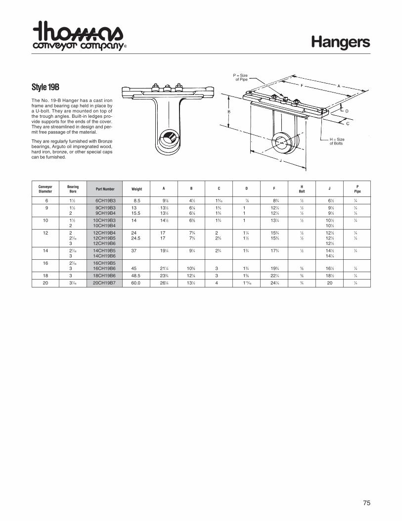
The No. 19B hangers have a cast iron frame and are mounted on top ofthe trough angles. Built-in ledges provide supports for the ends of thecover. They are streamline in design and permit free passage of thematerial. They are regularly furnished with Arguto oil impregnatedwood, hard iron, bronze, or other special caps can be furnished.

Style 19B

No. 216F hangers are designed for heavy duty applications and aremounted inside of flared trough. Hard iron or bronze bearings arenormally furnished; however, other bearings are available.

Air PurgedHanger

Air purged hangers are recommended when handling dusty and abra-sive materials which contribute to shutdowns and hanger bearing fail-ures. Air-swept hangers are available for 9”-24” conveyors. Theyshould not be used when handling hot materials (over 250º F) or wetsticky materials or when handling non abrasive materials when aninexpensive hanger will do the job satisfactorily. In service, air-purgedhangers deliver relatively trouble-free operation. They help solve noisenuisance problems, and they help reduce power requirement becauseof the low coefficient of fraction. Maximum trough loading should notexceed 15%. The air, at approximately 1-1/4 PSI enters the housing atthe top, passes over and around the bearing, and is dissipated aroundthe coupling shaft on both sides of the housing. Thus the bearing isprotected from dust and the material in the trough at all times. Only 3to 7 cu. ft. of air per minute is required to keep each hanger bearing clean.

70

Hangers

4 1 4CH2202 313⁄16 31⁄2 3⁄161⁄4 61⁄2 2 11⁄2 71⁄4 5⁄16 × 3 ⁄4 5

6 11⁄2 6CH2203 41⁄2 41⁄2 3⁄163⁄8 83⁄4 21⁄2 2 93⁄4 7⁄16 × 11⁄16 7

9 11⁄2 9CH2203 61⁄8 41⁄2 1⁄4 3⁄8 121⁄4 21⁄2 2 131⁄2 7⁄16 × 11⁄16 92 9CH2204 61⁄8 41⁄2 1⁄4 3⁄8 121⁄4 21⁄2 2 131⁄2 11

10 11⁄2 10CH2203 63⁄8 41⁄2 1⁄4 3⁄8 131⁄4 21⁄2 2 141⁄2 7⁄16 × 11⁄16 10 2 10CH2204 63⁄8 41⁄2 1⁄4 3⁄8 131⁄4 21⁄2 2 141⁄2 12

12 2 12CH2204 73⁄4 5 3⁄8 1⁄2 153⁄4 21⁄2 2 171⁄2 9⁄16 × 15⁄16 16 27⁄16 12CH2205 73⁄4 5 3⁄8 1⁄2 153⁄4 21⁄2 3 171⁄2 213 12CH2206 73⁄4 5 3⁄8 1⁄2 153⁄4 21⁄2 3 171⁄2 28

14 27⁄16 14CH2205 91⁄4 5 1⁄2 1⁄2 173⁄4 21⁄2 3 191⁄2 9⁄16 × 15⁄16 263 14CH2206 91⁄4 5 1⁄2 1⁄2 173⁄4 21⁄2 3 191⁄2 33

16 3 16CH2206 105⁄8 5 1⁄2 1⁄2 193⁄4 21⁄2 3 211⁄2 9⁄16 × 15⁄16 39

18 3 18CH2206 121⁄8 6 1⁄2 5⁄8 221⁄4 31⁄2 3 241⁄2 11⁄16 × 111⁄16 41 37⁄16 18CH2207 121⁄8 6 1⁄2 5⁄8 221⁄4 31⁄2 4 241⁄2 49

20 3 20CH2206 131⁄2 6 1⁄2 5⁄8 241⁄4 31⁄2 3 261⁄2 11⁄16 × 111⁄16 43 37⁄16 20CH2207 131⁄2 6 1⁄2 5⁄8 241⁄4 31⁄2 4 261⁄2 51

24 37⁄16 24CH2207 161⁄2 6 1⁄2 5⁄8 281⁄4 31⁄2 4 301⁄2 11⁄16 × 111⁄16 57

4 1 4CH2262 5 35⁄8 31⁄2 3⁄161⁄4 11⁄16 2 11⁄2 5⁄16 × 3⁄4 5

6 11⁄2 6CH2263 7 41⁄2 41⁄2 3⁄163⁄8 3⁄4 21⁄2 2 7⁄16 × 11⁄16 7

9 11⁄2 9CH2263 10 61⁄8 41⁄2 1⁄4 3⁄8 1 21⁄2 2 7⁄16 × 11⁄16 92 9CH2264 10 61⁄8 41⁄2 1⁄4 3⁄8 1 21⁄2 2 11

10 11⁄2 10CH2263 11 63⁄8 41⁄2 1⁄4 3⁄8 1 21⁄2 2 7⁄16 × 11⁄16 10 2 10CH2264 11 63⁄8 41⁄2 1⁄4 3⁄8 1 21⁄2 2 12

12 2 12CH2264 13 73⁄4 5 3⁄8 1⁄2 11⁄4 21⁄2 2 9⁄16 × 15⁄16 16 27⁄16 12CH2265 13 73⁄4 5 3⁄8 1⁄2 11⁄4 21⁄2 3 21 3 12CH2266 13 73⁄4 5 3⁄8 1⁄2 11⁄4 21⁄2 3 28

14 27⁄16 14CH2265 15 91⁄4 5 1⁄2 1⁄2 13⁄8 21⁄2 3 9⁄16 × 15⁄16 26 3 14CH2266 15 91⁄4 5 1⁄2 1⁄2 13⁄8 21⁄2 3 33

16 3 16CH2266 17 105⁄8 5 1⁄2 1⁄2 13⁄8 21⁄2 3 9⁄16 × 15⁄16 39

18 3 18CH2266 19 121⁄8 6 1⁄2 5⁄8 11⁄2 31⁄2 3 11⁄16 × 111⁄16 41 37⁄16 18CH2267 19 121⁄8 6 1⁄2 5⁄8 11⁄2 31⁄2 4 49

20 3 20CH2266 21 131⁄2 6 1⁄2 5⁄8 11⁄2 31⁄2 3 11⁄16 × 111⁄16 43 37⁄16 20CH2267 21 131⁄2 6 1⁄2 5⁄8 11⁄2 31⁄2 4 51

24 37⁄16 24CH2267 25 161⁄2 6 5⁄8 5⁄8 15⁄8 31⁄2 4 11⁄16 × 111⁄16 57

Style 220

No. 220 hangers are designed for mounting on top ofthe trough flanges and may be used where dust-tightor weather proof operation is not required. This typehanger allows for minimum obstruction of materialflow in high capacity conveyors. Available with frictiontype bearing.

*Refer to Page 76 for bearingsNOTE: For hangers with oil pipe add –O to part number

Conveyor Coupling PartDiameter Size Number* B C D E F H K L M Weight

Slot Each

Style 226

No. 226 hangers are designed for flush mountinginside the trough permitting dust-tight or weather-proof operation. This type hanger allows for minimumobstruction of material flow in high capacity convey-ors. Also available with friction type bearing.

*Refer to Page 76 for bearings *For hangers with oil pipe add –O to part number

A B C D E F H KConveyor Coupling PartDiameter Size Number*

M WeightSlot Each

Pipe Tap 1⁄8″

M SLOTBolts E

Pipe Tap 1⁄8″

M SLOTBolts E

71

Hangers

6 11⁄2 6CH2163 7 41⁄2 41⁄2 3⁄163⁄8 3⁄4 21⁄2 2 7⁄16 × 11⁄16 5

9 11⁄2 9CH2163 10 61⁄8 41⁄2 1⁄4 3⁄8 1 21⁄2 2 7⁄16 × 11⁄16 72 9CH2164 10 61⁄8 41⁄2 1⁄4 3⁄8 1 21⁄2 2 9

10 11⁄2 10CH2163 11 63⁄8 41⁄2 1⁄4 3⁄8 1 21⁄2 2 7⁄16 × 11⁄16 82 10CH2164 11 63⁄8 41⁄2 1⁄4 3⁄8 1 21⁄2 2 10

12 2 12CH2164 13 73⁄4 5 3⁄8 1⁄2 11⁄4 21⁄2 2 9⁄16 × 15⁄16 14 27⁄16 12CH2165 13 73⁄4 5 3⁄8 1⁄2 11⁄4 21⁄2 3 18 3 12CH2166 13 73⁄4 5 3⁄8 1⁄2 11⁄4 21⁄2 3 21

14 27⁄16 14CH2165 15 91⁄4 5 1⁄2 1⁄2 13⁄8 21⁄2 3 9⁄16 × 15⁄16 23 3 14CH2166 15 91⁄4 5 1⁄2 1⁄2 13⁄8 21⁄2 3 25

16 3 16CH2166 17 105⁄8 5 1⁄2 1⁄2 13⁄8 21⁄2 3 9⁄16 × 15⁄16 28

18 3 18CH2166 19 121⁄8 6 1⁄2 5⁄8 11⁄2 31⁄2 3 11⁄16 × 111⁄16 34 37⁄16 18CH2167 19 121⁄8 6 1⁄2 5⁄8 11⁄2 31⁄2 4 44

20 3 20CH2166 21 131⁄2 6 1⁄2 5⁄8 11⁄2 31⁄2 3 11⁄16 × 111⁄16 36 37⁄16 20CH2167 21 131⁄2 6 1⁄2 5⁄8 11⁄2 31⁄2 4 47

24 37⁄16 24CH2167 25 161⁄2 6 5⁄8 5⁄8 15⁄8 31⁄2 4 11⁄16 × 111⁄16 53

6 11⁄2 6CH2303 41⁄2 41⁄2 1⁄4 3⁄8 83⁄4 21⁄2 2 93⁄4 7⁄16 × 11⁄16 6

9 11⁄2 9CH2303 61⁄8 41⁄2 1⁄4 3⁄8 121⁄4 21⁄2 2 131⁄2 7⁄16 × 11⁄16 82 9CH2304 61⁄8 41⁄2 1⁄4 3⁄8 121⁄4 21⁄2 2 131⁄2 10

10 11⁄2 10CH2303 63⁄8 41⁄2 1⁄4 3⁄8 131⁄4 21⁄2 2 141⁄2 7⁄16 × 11⁄16 92 10CH2304 63⁄8 41⁄2 1⁄4 3⁄8 131⁄4 21⁄2 2 141⁄2 11

12 2 12CH2304 73⁄4 5 3⁄8 1⁄2 153⁄4 21⁄2 2 171⁄2 9⁄16 × 15⁄16 15 27⁄16 12CH2305 73⁄4 5 3⁄8 1⁄2 153⁄4 21⁄2 3 171⁄2 20 3 12CH2306 73⁄4 5 3⁄8 1⁄2 153⁄4 21⁄2 3 171⁄2 25

14 27⁄16 14CH2305 91⁄4 5 3⁄8 1⁄2 173⁄4 21⁄2 3 191⁄2 9⁄16 × 15⁄16 24 3 14CH2306 91⁄4 5 3⁄8 1⁄2 173⁄4 21⁄2 3 191⁄2 29

16 3 16CH2306 105⁄8 5 3⁄8 1⁄2 193⁄4 21⁄2 3 211⁄2 9⁄16 × 15⁄16 35

18 3 18CH2306 121⁄8 6 1⁄2 5⁄8 221⁄4 31⁄2 3 241⁄2 11⁄16 × 111⁄16 34 37⁄16 18CH2307 121⁄8 6 1⁄2 5⁄8 221⁄4 31⁄2 4 241⁄2 47

20 3 20CH2306 131⁄2 6 1⁄2 5⁄8 241⁄4 31⁄2 3 261⁄2 11⁄16 × 111⁄16 40 37⁄16 20CH2307 131⁄2 6 1⁄2 5⁄8 241⁄4 31⁄2 4 261⁄2 49

24 37⁄16 24CH2307 161⁄2 6 5⁄8 5⁄8 281⁄4 33⁄4 4 301⁄2 11⁄16 × 111⁄16 55

Style 216

No. 216 hangers are designed for heavy duty appli-cations. This hanger is flush mounted inside thetrough permitting dust tight or weather proof opera-tion. Hard iron or bronze bearings are normally fur-nished; however, the hanger can be furnished withother bearings.

*Refer to Page 76 for bearings *For hangers with oil pipe add –O to part number

Conveyor Coupling PartDiameter Size Number* A B C D E F H K M Weight

Slot Each

Style 230

No. 230 hangers are designed for heavy duty appli-cations where mounting on top of the trough flange isrequired. Hard iron or bronze bearings are normallyfurnished; however, other bearings are available.

*Refer to Page 76 for bearings *For hangers with oil pipe add –O to part number

B C D E F H K LConveyor Coupling PartDiameter Size Number*

M WeightSlot Each

Pipe Tap 1⁄8″M SLOT

Bolts E

Pipe Tap 1⁄8″

M SLOT

Bolts E

72

Hangers

6 11⁄2 6CH3163 6CH3263 7 41⁄2 6 3⁄163⁄8 3⁄4 41⁄2 2

9 11⁄2 9CH3163 9CH3263 10 61⁄8 6 3⁄163⁄8 1 41⁄2 2

2 9CH3164 9CH3264 10 61⁄8 6 3⁄163⁄8 1 41⁄2 2

10 11⁄2 10CH3163 10CH3263 11 63⁄8 6 3⁄163⁄8 1 41⁄2 2

2 10CH3164 10CH3264 11 63⁄8 6 3⁄163⁄8 1 41⁄2 2

12 2 12CH3164 12CH3264 13 73⁄4 61⁄2 1⁄4 1⁄2 11⁄4 5 227⁄16 12CH3165 12CH3265 13 73⁄4 61⁄2 1⁄4 1⁄2 11⁄4 5 33 12CH3166 12CH3266 13 73⁄4 61⁄2 1⁄4 1⁄2 11⁄4 5 3

14 27⁄16 14CH3165 14CH3265 15 91⁄4 61⁄2 1⁄4 1⁄2 13⁄8 5 33 14CH3166 14CH3266 15 91⁄4 61⁄2 1⁄4 1⁄2 13⁄8 5 3

16 3 16CH3166 16CH3266 17 105⁄8 61⁄2 1⁄4 1⁄2 13⁄8 5 318 3 18CH3166 18CH3266 19 121⁄8 61⁄2 1⁄4 5⁄8 15⁄8 51⁄4 3

37⁄16 18CH3167 18CH3267 19 121⁄8 7 1⁄4 5⁄8 15⁄8 51⁄4 420 3 20CH3166 20CH3266 21 131⁄2 7 1⁄4 5⁄8 15⁄8 51⁄4 3

37⁄16 20CH3167 20CH3267 21 131⁄2 7 1⁄4 5⁄8 15⁄8 51⁄4 424 37⁄16 24CH3167 24CH3267 25 161⁄2 7 1⁄4 5⁄8 13⁄4 51⁄4 4

9 9CHAPH3 11⁄2 15 10 3⁄8 41⁄2 61⁄8 11⁄4 1 2 1⁄49CHAPH4 2 20 3⁄8

12 12CHAPH4 2 30 13 1⁄2 5 71⁄4 11⁄4 11⁄4 2 1⁄412CHAPH5 27⁄16 52 3 12CHAPH6 3 68 3

14 14CHAPH5 27⁄16 60 15 1⁄2 5 91⁄4 11⁄4 13⁄8 3 3⁄814CHAPH6 3 74

16 16CHAPH6 3 77 17 1⁄2 5 105⁄8 11⁄4 13⁄8 3 1⁄818 18CHAPH6 3 91 19 5⁄8 6 121⁄8 13⁄4 15⁄8 3 1⁄220 20CHAPH6 3 105 21 5⁄8 6 131⁄2 13⁄4 13⁄8 3 1⁄2

20CHAPH7 37⁄16 140 424 24CHAPH7 37⁄16 155 25 5⁄8 6 161⁄2 13⁄4 15⁄8 4 1⁄2

A B C D E F H K

A B C D F H L T

ConveyorDiameter

CouplingSize Style

316*Style326*

Part Number

ScrewDiameter

PartNumber

ShaftDia.

WeightEach

Space required on coupling for hanger. Dimensions in inches.Air supply should be clean and dry. Weight in pounds.

Air Purged HangerAir purged hangers are recommendedwhen handling dusty and abrasive materi-als which contribute to shut-downs andhanger bearing failures. They should notbe used when handling hot materials (over250°F) or wet sticky materials or whenhandling nonabrasive materials when aninexpensive hanger will do the job satisfac-torily. Maximum trough loading should notexceed 15%. The air, at approximately 11⁄4PSI, enters the housing at the top, passesover and around the bearing, and is dissi-pated around the coupling shaft on bothsides of the housing. Only 3 to 7 cu. ft. ofair per minute is required to keep eachhanger bearing clean.

Style 316No. 316 hangers are designed for heavy dutyuse in conveyors where abnormal heatrequires unequal expansion between thescrew and conveyor trough. Hard iron orbronze bearings are normally used; however,this hanger can be furnished with other bear-ings.

Style 326No. 326 hangers are designed to permit mini-mum obstruction of material flow and are usedin conveyors where abnormal heat requiresunequal expansion between the screw and theconveyor trough. Hard iron or bronze bearingsare normally used, but other type bearings areavailable.

Pipe Tap 1⁄8″

Bolts E

Pipe Tap 1⁄8″

Bolts E

B - BoltSize

StandardCoupling

*Refer to Page 76 for bearings *For hangers with oil pipe add –O to part number

73

Hangers

6 11⁄2 6CH216F3 14 7 4 3⁄163⁄8 7⁄8 21⁄2 2 9 7⁄16 × 3⁄4

9 11⁄2 9CH216F3 18 9 4 3⁄163⁄8 7⁄8 21⁄2 2 14 7⁄16 × 3⁄4

2 9CH216F4 17

12 2 12CH216F4 22 10 5 3⁄8 1⁄2 11⁄8 21⁄2 2 24 9⁄16 × 3⁄427⁄16 12CH216F5 3 28 3 12CH216F6 32

14 27⁄16 14CH216F5 24 11 5 3⁄8 1⁄2 11⁄8 21⁄2 3 31 9⁄16 × 3⁄43 14CH216F6 34

16 3 16CH216F6 28 111⁄2 5 3⁄8 1⁄2 11⁄8 21⁄2 3 38 9⁄16 × 3⁄4

18 3 18CH216F6 31 121⁄8 5 1⁄2 5⁄8 11⁄2 31⁄2 3 52 11⁄16 × 7⁄837⁄16 18CH216F7 4 61

20 3 20CH216F6 34 131⁄2 5 1⁄2 5⁄8 11⁄2 31⁄2 3 55 11⁄16 × 7⁄837⁄16 20CH216F7 4 64

24 37⁄16 24CH216F7 40 161⁄2 5 1⁄2 5⁄8 11⁄2 31⁄2 4 71 11⁄16 × 7⁄8

6 11⁄2 6CH303 31⁄2 41⁄4 11⁄2 3⁄8 5⁄16 31⁄8 1⁄2 2 3

9 11⁄2 9CH303 5 57⁄8 11⁄2 3⁄8 3⁄8 41⁄4 1⁄2 2 62 9CH304 5 57⁄8 11⁄2 1⁄2 3⁄8 41⁄4 1⁄2 2 8

10 11⁄2 10CH303 51⁄2 63⁄8 11⁄2 3⁄8 1⁄2 43⁄8 3⁄4 2 82 10CH304 51⁄2 63⁄8 11⁄2 1⁄2 1⁄2 43⁄8 3⁄4 2 9

12 2 12CH304 61⁄2 71⁄2 11⁄2 1⁄2 1⁄2 51⁄2 3⁄4 2 12 27⁄16 12CH305 61⁄2 71⁄2 2 1⁄2 1⁄2 51⁄2 3⁄4 3 18 3 12CH306 61⁄2 71⁄2 2 1⁄2 1⁄2 51⁄2 3⁄4 3 20

14 27⁄16 14CH305 71⁄2 9 2 1⁄2 5⁄8 67⁄8 7⁄8 3 20 3 14CH306 71⁄2 9 2 1⁄2 5⁄8 67⁄8 7⁄8 3 22

16 3 16CH306 81⁄2 103⁄8 2 5⁄8 5⁄8 8 1 3 32

18 3 18CH306 91⁄2 117⁄8 2 3⁄4 5⁄8 9 11⁄4 3 30 37⁄16 18CH307 91⁄2 117⁄8 3 3⁄4 5⁄8 9 11⁄4 4 33

20 3 20CH306 101⁄2 131⁄4 2 3⁄4 5⁄8 101⁄4 11⁄4 3 32 37⁄16 20CH307 101⁄2 131⁄4 3 3⁄4 5⁄8 101⁄4 11⁄4 4 38

24 37⁄16 24CH307 121⁄2 161⁄4 3 3⁄4 3⁄4 123⁄4 11⁄2 4 46

A B C D E F G H

A B C D E F H K

Style 30No. 30 hangers are designed for side mountingwithin the conveyor trough on the non-carryingside and permit a minimum of obstruction of mater-ial flow. Available with friction type bearing.

*Refer to Page 76 for bearingsNOTE: For hangers with oil pipe add –O to part number

Conveyor Coupling PartDiameter Diameter Number*

WeightEach

Style 216FNo. 216F hangers are designed forheavy duty applications and aremounted inside of flared trough.Hard iron or bronze bearings arenormally furnished; however, otherbearings are available.

*Refer to Page 76 for bearingsNOTE: For hangers with oil pipe add –O to part number

Conveyor Coupling PartDiameter Diameter Number*

Weight MEach Slot

Bolts E

1⁄8″ Pipe Tap

M Slot

Bolts E

C

74

Hangers

6 11⁄2 6CH603 93⁄4 41⁄2 4 3⁄163⁄8 83⁄4 111⁄16 2 7 7⁄16 × 11⁄16

9 11⁄2 9CH603 131⁄2 61⁄8 4 1⁄4 3⁄8 121⁄4 111⁄16 2 8 7⁄16 × 11⁄16

2 9CH604 131⁄2 61⁄8 4 1⁄4 3⁄8 121⁄4 13⁄4 2 9 7⁄16 × 11⁄16

10 11⁄2 10CH603 141⁄2 63⁄8 4 1⁄4 3⁄8 131⁄4 111⁄16 2 9 7⁄16 × 15⁄16

2 10CH604 141⁄2 63⁄8 4 1⁄4 3⁄8 131⁄4 13⁄4 2 10 7⁄16 × 15⁄16

12 2 12CH604 171⁄2 73⁄4 5 3⁄8 1⁄2 153⁄4 13⁄4 21⁄2 12 9⁄16 × 15⁄16

27⁄16 12CH605 171⁄2 73⁄4 5 3⁄8 1⁄2 153⁄4 163⁄64 21⁄2 20 9⁄16 × 15⁄16

3 12CH606 171⁄2 73⁄4 5 3⁄8 1⁄2 153⁄4 211⁄16 21⁄2 30 9⁄16 × 15⁄16

14 27⁄16 14CH605 191⁄2 91⁄4 5 1⁄2 1⁄2 173⁄4 163⁄64 21⁄2 21 9⁄16 × 15⁄16

3 14CH606 191⁄2 91⁄4 5 1⁄2 1⁄2 173⁄4 211⁄32 21⁄2 32 9⁄16 × 15⁄16

16 3 16CH606 211⁄2 105⁄8 5 1⁄2 1⁄2 193⁄4 211⁄32 21⁄2 35 9⁄16 × 15⁄16

18 3 18CH606 241⁄2 121⁄8 6 1⁄2 5⁄8 221⁄4 211⁄32 31⁄2 40 11⁄16 × 111⁄16

20 3 20CH606 261⁄2 131⁄2 6 1⁄2 5⁄8 241⁄4 211⁄32 31⁄2 45 11⁄16 × 111⁄16

24 37⁄16 24CH607 301⁄2 161⁄2 6 5⁄8 5⁄8 281⁄4 231⁄64 33/4 58 11⁄16 × 111⁄16

6 11⁄2 6CH703 7 41⁄2 41⁄2 3⁄4 3⁄8 3⁄16 111⁄16 11/2 7 7⁄16 × 11⁄16

9 11⁄2 9CH703 10 61⁄8 41⁄2 1 3⁄8 1⁄4 111⁄16 13⁄4 8 7⁄16 × 11⁄16

2 9CH704 10 61⁄8 41⁄2 1 3⁄8 1⁄4 13⁄4 13⁄4 9

10 11⁄2 10CH703 11 63⁄8 41⁄2 1 3⁄8 1⁄4 111⁄16 13⁄4 9 7⁄16 × 11⁄16

2 10CH704 11 63⁄8 41⁄2 1 3⁄8 1⁄4 13⁄4 13⁄4 10

12 2 12CH704 13 73⁄4 5 11⁄4 1⁄2 3⁄8 13⁄4 21⁄8 12 9⁄16 × 15⁄16

27⁄16 12CH705 13 73⁄4 5 11⁄4 1⁄2 3⁄8 163⁄64 21⁄8 20 3 12CH706 13 73⁄4 5 11⁄4 1⁄2 3⁄8 211⁄32 21⁄8 30

14 27⁄16 14CH705 15 91⁄4 5 13⁄8 1⁄2 1⁄2 163⁄64 21⁄4 21 9⁄16 × 15⁄16

3 14CH706 15 91⁄4 5 13⁄8 1⁄2 1⁄2 211⁄32 21⁄4 32

16 3 16CH706 17 105⁄8 5 13⁄8 1⁄2 1⁄2 211⁄32 21⁄4 35 9⁄16 × 15⁄16

18 3 18CH706 19 121⁄8 6 11⁄2 5⁄8 1⁄2 211⁄32 21⁄2 40 11⁄16 × 111⁄16

20 3 20CH706 21 131⁄2 6 11⁄2 5⁄8 1⁄2 211⁄32 21⁄2 45 11⁄16 × 111⁄16

24 37⁄16 24CH707 25 161⁄2 6 15⁄8 5⁄8 5⁄8 211⁄32 25⁄8 58 11⁄16 × 111⁄16

A B C D E F H J

A B C D E F G H

*For hangers with oil pipe add –O to part number

*For hangers with oil pipe add –O to part number

Conveyor Coupling PartDiameter Size Number*

Weight MEach Slot

Style 70No. 70 hangers are furnished with aheavy duty, permanently lubricatedand sealed, self aligning ball bear-ing which permits temperatures upto 245º F. and will allow for up to 4ºshaft misalignment. This hanger ismounted inside the trough. Greasefitting can be furnished if specified.

Conveyor Coupling PartDiameter Size Number*

Weight MEach Slot

Style 60No. 60 hangers are furnished with a heavyduty, permanently lubricated and sealed,self-aligning ball bearing which permits tem-peratures up to 245º F. and will allow for upto 4º shaft misalignment. This hanger ismounted on top of the trough flanges.Grease fitting can be furnished if specified.

M Slot

Bolts E

M SlotBolts E

75

Hangers

6 11⁄2 6CH19B3 8.5 97⁄8 41⁄2 15⁄167⁄8 83⁄4 1⁄2 61⁄2 1⁄4

9 11⁄2 9CH19B3 13 131⁄2 61⁄8 13⁄4 1 121⁄4 1⁄2 91⁄2 1⁄42 9CH19B4 15.5 131⁄2 61⁄8 13⁄4 1 121⁄4 1⁄2 91⁄2 1⁄4

10 11⁄2 10CH19B3 14 141⁄2 63⁄8 13⁄4 1 131⁄4 1⁄2 101⁄2 1⁄42 10CH19B4 101⁄2

12 2 12CH19B4 24 17 73⁄4 2 11⁄4 153⁄4 1⁄2 121⁄2 1⁄427⁄16 12CH19B5 24.5 17 73⁄4 23⁄4 11⁄2 153⁄4 1⁄2 121⁄2 1⁄43 12CH19B6 121⁄2

14 27⁄16 14CH19B5 37 191⁄4 91⁄4 23⁄4 13⁄4 173⁄4 1⁄2 141⁄2 1⁄43 14CH19B6 141⁄4

16 27⁄16 16CH19B5 3 16CH19B6 45 211⁄4 105⁄8 3 13⁄4 193⁄4 5⁄8 161⁄2 1⁄4

18 3 18CH19B6 48.5 233⁄4 121⁄8 3 15⁄8 221⁄4 5⁄8 181⁄2 1⁄4

20 37⁄16 20CH19B7 60.0 261⁄4 131⁄2 4 113⁄16 241⁄4 3⁄4 20 1⁄4

A B C D F JConveyor BearingDiameter Bore

HBolt

PPipePart Number Weight

Style 19BThe No. 19-B Hanger has a cast ironframe and bearing cap held in place bya U-bolt. They are mounted on top ofthe trough angles. Built-in ledges pro-vide supports for the ends of the cover.They are streamlined in design and per-mit free passage of the material.

They are regularly furnished with Bronzebearings, Arguto oil impregnated wood,hard iron, bronze, or other special capscan be furnished.

P = Sizeof Pipe

H = Sizeof Bolts

76

Screw Conveyor HangerBearing Selection Application

MAXIMUM MATERIAL SOMEBEARING OPERATING STYLES FDA SELF SUGGESTED COMMENTS

MATERIAL TEMP (ºF) AVAILABLE APPROVED LUBE USES

MartinHARD IRON

500º 220 Yes Chemical, Cement,Aggregate

Requires Hardenedshafts.

CASTHARDIRON(45-50 Rockwell C)

500º 220, 216 Lime, Cement,Salt, Gypsum

Requires hardened shaft.Can be noisy. Lubricationrequired in some applica-tions.

WOOD 160º 220, 216 Yes Grain, Feed, Fertilizer Good general purpose.

MartinBRONZE

850º 220 Yes Grain, Feed,Processing

High quality bearings.High load capacity.

NYLON 250º 220 Yes Yes Food and Grain For dry applications.

PLASTECH 300º 220 YesChemical, Food,Grain

Good general purpose.

UHMW 225º 220, 216 Yes Yes Food Material USDA approved.Does not swell in water.

STELLITE 1000º 220, 216 Chemical, Cement,Aggregate

Requires Stellite insert inshaft.

INDUSTRIALGRADE ENGINEEREDNYLON

160º 220 Yes Grain, Feed, Fertilizer Economical replacementfor wood.

WHITEMELAMINE 250º 220 Yes Food Industry Recommended for sugar.

FOOD GRADEENGINEEREDNYLON

300º 220 Yes Yes Food, Grain, Fertilizer For dry application.

BALLBEARING

180º 60, 70 Non-abrasive applications General purpose use.

MartinHDPE

200º 220 Yes Yes Grain, Feed,Chemical Handling

Recommended for non-abrasive applications.

CERAMIC 1,000º 220, 216 Yes Chemical, Cement,Food

Requires Hardenedshafts.

Yes

77

11⁄2 CHB18B3*

2 CHB18B4*

19B 27⁄16 CHB18B5*

3 CHB18B6*

37⁄16 CHB18B7*

216 11⁄2 CHB2163*

2 CHB2164*

230 27⁄16 CHB2165*

3 CHB2166*

316 37⁄16 CHB2167*

11⁄2 CHB2203*

2 CHB2204*

27⁄16 CHB2205*

3 CHB2206*

37⁄16 CHB2207*

11⁄2 CHB603

2 CHB604

27⁄16 CHB605

3 CHB606

37⁄16 CHB607

220

226

326

30

60

70

*H—Cast Hard Iron *W—Wood *O—Oil Hole Top Cap *BR – Bronze *U—UHMW *G—Gatke *C—Ceramic * St—Stellite

*BR — Bronze *H — Cast Hard Iron *W — Wood *N — Nylatron *P – HDPE *PL - Plastech

*MHI — Hard iron (oil impregnated) *MCB — Melamine *C – Ceramic *WN – White Nylon *ST - Stellite

*MBR — Bronze (oil impregnated) *U — UHMW *UR – Urethane * G - Gatke

Note: New style bearings are available with slinger shield one side.

*W—Wood *H—Cast Hard Iron *N—Nylatron *BR—Bronze *G—Gatke

Note: Furnished as bottom cap only

Hanger Type Bore Part Number Bearing

Hanger Type Bore Part Number Bearing

Hanger Type Bore Part Number Bearing

Hanger Type Bore Part Number Bearing

Hanger Bearings

BallBearing

BallBearing

pages 65 - 80 4/21/05 9:48 AM Page 77

78

Trough Ends

Trough Ends

Conveyor Diameter

TE — Outside W/O Feet TEF — Outside W/Feet TEI — Inside TER — Inside Rectangular TEO — Single Bearing Pedestal FTEF — Outside Flared W/Feet FTE — Outside Flared W/O Feet FTEO — Single Bearing Flared Pedestal FTDO — Flared Discharge End TDO — Outside Discharge End TDI — Inside Discharge End CHTE — Outside Tubular W/O Feet CHTEF — Outside Tubular W/Feet

Type

Coupling Diameter 2 — 1" 5 — 2-7/16" 3 — 1-1/2" 6 — 3" 4 — 2" 7 —3-7/16"

Plate OnlyBearing Type BB - Ball / Bronze RB - Roller

9 3 -BB -PTEF

U-TROUGH TUBULAR FLARED RECTANGULARTROUGH TROUGH TROUGH

OUTSIDETROUGH

ENDSWITHFEET

INSIDEPATTERNTROUGH

ENDS

OUTSIDETROUGH

ENDSWITHOUT

FEET

DISCHARGETROUGH

ENDS

OUTBOARDBEARINGTROUGH

ENDSSINGLE

Most common typeused as trough support

is included.

Trough support notincluded.

Used where space islimited or trough doesnot have end flange.

For end discharge con-veyors. Special flange

bearing required.

Used whencompression type

packing gland seal orsplit gland seal

required.

Availableon

application

Availableon

application

Availableon

application

79

Trough Ends

4 1 4TEF2–* 35⁄8 45⁄8 215⁄16 15⁄8 — 17⁄16 53⁄4 1 15⁄8 1⁄4 81⁄8 3⁄8 3⁄8 4 7⁄16 × 9⁄16

6 11⁄2 6TEF3–* 41⁄2 55⁄8 315⁄16 23⁄16 311⁄16 11⁄2 81⁄8 1 13⁄4 1⁄4 101⁄8 3⁄8 3⁄8 7 7⁄16 × 9⁄16

9 11⁄2 9TEF3–* 61⁄8 77⁄8 315⁄16 23⁄16 311⁄16 15⁄8 93⁄8 11⁄2 25⁄8 1⁄4 133⁄4 1⁄2 3⁄8 12 7⁄16 × 9⁄16

2 9TEF4–* 61⁄8 77⁄8 415⁄16 21⁄2 313⁄16 15⁄8 93⁄8 11⁄2 25⁄8 1⁄4 133⁄4 1⁄2 3⁄8 12 7⁄16 × 9⁄16

10 11⁄2 10TEF3–* 63⁄8 87⁄8 315⁄16 23⁄16 311⁄16 13⁄4 91⁄2 13⁄4 27⁄8 1⁄4 143⁄4 1⁄2 3⁄8 14 7⁄16 × 9⁄16

2 10TEF4–* 63⁄8 87⁄8 415⁄16 21⁄2 313⁄16 13⁄4 91⁄2 13⁄4 27⁄8 1⁄4 143⁄4 1⁄2 3⁄8 14 7⁄16 × 9⁄16

12 2 12TEF4–* 73⁄4 95⁄8 5 29⁄16 37⁄8 2 121⁄4 15⁄8 23⁄4 1⁄4 171⁄4 5⁄8 1⁄2 23 9⁄16 × 11⁄16

27⁄16 12TEF5–* 73⁄4 95⁄8 51⁄2 215⁄16 47⁄16 2 121⁄4 15⁄8 23⁄4 1⁄4 171⁄4 5⁄8 1⁄2 23 9⁄16 × 11⁄16

3 12TEF6–* 73⁄4 95⁄8 55⁄8 33⁄4 415⁄16 2 121⁄4 15⁄8 23⁄4 1⁄4 171⁄4 5⁄8 1⁄2 23 9⁄16 × 11⁄16

14 27⁄16 14TEF5–* 91⁄4 107⁄8 51⁄2 215⁄16 47⁄16 2 131⁄2 15⁄8 27⁄8 1⁄4 191⁄4 5⁄8 1⁄2 38 9⁄16 × 11⁄16

3 14TEF6–* 91⁄4 107⁄8 55⁄8 33⁄4 415⁄16 2 131⁄2 15⁄8 27⁄8 1⁄4 191⁄4 5⁄8 1⁄2 38 9⁄16 × 11⁄16

16 3 16TEF6–* 105⁄8 12 511⁄16 313⁄16 5 21⁄2 147⁄8 2 31⁄4 5⁄16 211⁄4 5⁄8 5⁄8 45 11⁄16 × 13⁄16

18 3 18TEF6–* 121⁄8 133⁄8 511⁄16 313⁄16 5 21⁄2 16 2 31⁄4 3⁄8 241⁄2 5⁄8 5⁄8 67 11⁄16 × 13⁄16

37⁄16 18TEF7–* 121⁄8 133⁄8 615⁄16 45⁄16 59⁄16 21⁄2 16 2 31⁄4 3⁄8 241⁄4 5⁄8 5⁄8 67 11⁄16 × 13⁄16

20 3 20TEF6–* 131⁄2 15 53⁄4 37⁄8 51⁄16 21⁄2 191⁄4 21⁄4 33⁄4 3⁄8 261⁄4 3⁄4 5⁄8 120 11⁄16 × 13⁄16

37⁄16 20TEF7–* 131⁄2 15 7 43⁄8 55⁄8 21⁄2 191⁄4 21⁄4 33⁄4 3⁄8 261⁄4 3⁄4 5⁄8 120 11⁄16 × 13⁄16

24 37⁄16 24TEF7–* 161⁄2 181⁄8 7 43⁄8 55⁄8 21⁄2 20 21⁄2 41⁄8 3⁄8 301⁄4 3⁄4 5⁄8 162 11⁄16 × 13⁄16

4 1 4TE2–* 35⁄8 23⁄16 15⁄8 17⁄161⁄4 81⁄8 3⁄8 3 7⁄16 × 9⁄16

6 11⁄2 6TE3–* 41⁄2 33⁄16 23⁄16 311⁄16 11⁄2 1⁄4 101⁄8 3⁄8 4 7⁄16 × 9⁄16

9 11⁄2 9TE3–* 61⁄8 31⁄4 23⁄16 311⁄16 15⁄8 1⁄4 133⁄4 3⁄8 9 7⁄16 × 9⁄16

2 9TE4–* 61⁄8 41⁄4 21⁄2 313⁄16 15⁄8 1⁄4 133⁄4 3⁄8 9

10 11⁄2 10TE3–* 63⁄8 31⁄4 23⁄16 311⁄16 13⁄4 1⁄4 143⁄4 3⁄8 11 7⁄16 × 9⁄16

2 10TE4–* 63⁄8 41⁄4 21⁄2 313⁄16 13⁄4 1⁄4 143⁄4 3⁄8 11 7⁄16 × 9⁄16

12 2 12TE4–* 73⁄4 41⁄4 29⁄16 37⁄8 2 1⁄4 171⁄4 1⁄2 2027⁄16 12TE5–* 73⁄4 51⁄4 215⁄16 47⁄16 2 1⁄4 171⁄4 1⁄2 20 9⁄16 × 11⁄16

3 12TE6–* 73⁄4 61⁄4 33⁄4 415⁄16 2 1⁄4 171⁄4 1⁄2 20

14 27⁄16 14TE5–* 91⁄4 55⁄16 215⁄16 47⁄16 2 1⁄4 191⁄4 1⁄2 35 9⁄16 × 11⁄16

3 14TE6–* 91⁄4 55⁄16 33⁄4 415⁄16 2 1⁄4 191⁄4 1⁄2 35

16 3 16TE6–* 105⁄8 65⁄16 313⁄16 5 21⁄2 5⁄16 211⁄4 5⁄8 42 11⁄16 × 13⁄16

18 3 18TE6–* 121⁄8 63⁄8 313⁄16 5 21⁄2 3⁄8 241⁄4 5⁄8 60 11⁄16 × 13⁄16

37⁄16 18TE7–* 121⁄8 73⁄8 45⁄16 59⁄16 21⁄2 3⁄8 241⁄4 5⁄8 60

20 3 20TE6–* 131⁄2 63⁄8 37⁄8 51⁄16 21⁄2 3⁄8 261⁄4 5⁄8 90 11⁄16 × 13⁄16

37⁄16 20TE7–* 131⁄2 73⁄8 43⁄8 55⁄8 21⁄2 3⁄8 261⁄4 5⁄8 90

24 37⁄16 24TE7–* 161⁄2 73⁄8 43⁄8 55⁄8 21⁄2 3⁄8 301⁄4 5⁄8 120 11⁄16 × 13⁄16

Conveyor Shaft s PartDiameter Diameter Number

D

Friction Ball RollerBearing Bearing Bearing

B C E F H J K L M N Weight PSlot

Conveyor Shaft s PartDiameter Diameter Number

D

Friction Ball RollerBearing Bearing Bearing

B E K L N Weight PSlot

Outside With Feet

Outside trough ends with feet are used to supportend bearing, cover and trough. Drilling for bronzeor flanged ball bearing is standard.

Outside Less Feet

Outside trough ends less feet are used to supportend bearing and cover when no trough support isrequired. Drilling for bronze bearing or flanged ballbearing is standard.

s Can be furnished with CSP, CSW, or CSFP seals –*BB Ball / Bronze Bearing –*RB Roller Bearing–*P Less Bearing

Bolts - N

P SLOT

P SLOTBolts - N

Bolts - M

B

K E

80

Trough Ends

Conveyor Shaft s PartDiameter Diameter Number

D

Friction Ball RollerBearing Bearing Bearing

A B E K N Weight

Conveyor Shaft s PartDiameter Diameter Number

D

Friction Ball RollerBearing Bearing Bearing

A B C E K N Weight

Inside Rectangular

Rectangular trough ends are used inside of rec-tangular trough. Drilling for bronze bearing orflanged ball bearing is standard.

Inside

Inside trough ends are used in place of outsidetype where no trough end flanges are required.Drilling for bronze bearings or flanged ball bearingis standard.

s Can be furnished with CSP, CSW, or CSS seals –*BB Ball / Bronze Bearing –*RB Roller Bearing–*P Less Bearing

4 1 4TER2–* 5 35⁄8 21⁄2 23⁄16 15⁄8 — 2 1⁄4 1⁄4 4

6 11⁄2 6TER3–* 7 41⁄2 31⁄2 33⁄16 23⁄16 311⁄16 2 1⁄4 5⁄16 6

9 11⁄2 9TER3–* 10 61⁄8 5 31⁄4 23⁄16 311⁄16 2 1⁄4 3⁄8 92 9TER4–* 10 61⁄8 5 41⁄4 21⁄2 313⁄16 2 1⁄4 3⁄8 9

10 11⁄2 10TER3–* 11 63⁄8 51⁄2 31⁄4 23⁄16 311⁄16 2 1⁄4 3⁄8 12 2 10TER4–* 11 63⁄8 51⁄2 41⁄4 21⁄2 313⁄16 2 1⁄4 3⁄8 12

12 2 12TER4–* 13 73⁄4 61⁄2 41⁄4 29⁄16 37⁄8 2 1⁄4 1⁄2 21 27⁄16 12TER5–* 13 73⁄4 61⁄2 51⁄4 215⁄16 47⁄16 2 1⁄4 1⁄2 21 3 12TER6–* 13 73⁄4 61⁄2 61⁄4 33⁄4 415⁄16 2 1⁄4 1⁄2 21

14 27⁄16 14TER5–* 15 91⁄4 71⁄2 55⁄16 215⁄16 47⁄16 2 1⁄4 1⁄2 35 3 14TER6–* 15 91⁄4 71⁄2 65⁄16 33⁄4 415⁄16 2 1⁄4 1⁄2 35

16 3 16TER6–* 17 105⁄8 81⁄2 65⁄16 313⁄16 5 2 5⁄165⁄8 41

18 3 18TER6–* 19 121⁄8 91⁄2 63⁄8 313⁄16 5 2 3⁄8 5⁄8 60 37⁄16 18TER7–* 19 121⁄8 91⁄2 73⁄8 45⁄16 59⁄16 2 3⁄8 5⁄8 60

20 3 20TER6–* 21 131⁄2 101⁄2 63⁄8 37⁄8 51⁄16 2 3⁄8 5⁄8 88 37⁄16 20TER7–* 21 131⁄2 101⁄2 73⁄8 43⁄8 55⁄8 2 3⁄8 5⁄8 88

24 37⁄16 24TER7–* 25 161⁄2 121⁄2 73⁄8 43⁄8 55⁄8 2 3⁄8 5⁄8 125

Bolts - N

Bolts - N

4 1 4TEI2–* 5 35⁄8 23⁄16 15⁄8 — 2 1⁄4 1⁄4 3

6 11⁄2 6TEI3–* 7 41⁄2 33⁄16 23⁄16 311⁄16 2 1⁄4 5⁄16 5

9 11⁄2 9TEI3–* 10 61⁄8 31⁄4 23⁄16 311⁄16 2 1⁄4 3⁄8 92 9TEI4–* 10 61⁄8 41⁄4 21⁄2 313⁄16 2 1⁄4 3⁄8 9

10 11⁄2 10TEI3–* 11 63⁄8 31⁄4 23⁄16 311⁄16 2 1⁄4 3⁄8 11 2 10TEI4–* 11 63⁄8 41⁄4 21⁄2 313⁄16 2 1⁄4 3⁄8 11

12 2 12TEI4–* 13 73⁄4 41⁄4 29⁄16 37⁄8 2 1⁄4 1⁄2 1927⁄16 12TEI5–* 13 73⁄4 51⁄4 215⁄16 47⁄16 2 1⁄4 1⁄2 19 3 12TEI6–* 13 73⁄4 61⁄4 33⁄4 415⁄16 2 1⁄4 1⁄2 19

14 27⁄16 14TEI5–* 15 91⁄4 55⁄16 215⁄16 47⁄16 2 1⁄4 1⁄2 34 3 14TEI6–* 15 91⁄4 65⁄16 33⁄4 415⁄16 2 1⁄4 1⁄2 34

16 3 16TEI6–* 17 105⁄8 65⁄16 313⁄16 5 2 5⁄165⁄8 40

18 3 18TEI6–* 19 121⁄8 63⁄8 313⁄16 5 2 3⁄8 5⁄8 58 37⁄16 18TEI7–* 19 121⁄8 73⁄8 45⁄16 59⁄16 2 3⁄8 5⁄8 58

20 3 20TEI6–* 21 131⁄2 63⁄8 37⁄8 51⁄16 2 3⁄8 5⁄8 83 37⁄16 20TEI7–* 21 131⁄2 73⁄8 43⁄8 55⁄8 2 3⁄8 5⁄8 83

24 37⁄16 24TEI7–* 25 161⁄2 73⁄8 43⁄8 55⁄8 2 3⁄8 5⁄8 116

B

D

K

D

E

81

Trough Ends

Single Bearing

Single bearing pedestal type trough ends areconstructed with base for mounting pillow blockbearings and shaft seal or packing gland.

6 11⁄2 6TEO3

9 11⁄2 9TEO32 9TEO4

10 11⁄2 10TEO32 10TEO4

12 2 12TEO427⁄16 12TEO53 12TEO6

14 27⁄16 14TEO53 14TEO6

16 3 16TEO6

18 3 18TEO637⁄16 18TEO7

20 3 20TEO637⁄16 20TEO7

24 37⁄16 24TEO7

Conveyor Shaft PartDiameter Diameter Number B C D E F H J K L M N P

Slot Weight

ConsultFactory

P SLOT

Bolts - N

Bolts - M

82

Trough Ends

6 11⁄2 6FTEF3.* 15 6FTE3–* 13 6FTEO3–* 22 6FTDO3–** 11

9 11⁄2 9FTEF3–* 22 9FTE3–* 19 9FTEO3–* 31 9FTDO3–** 152 9FTEF4–* 27 9FTE4–* 24 9FTEO4–* 36 9FTDO4–** 20

12 2 12FTEF4–* 43 12FTE4–* 36 12FTEO4–* 63 12FTDO4–** 2827⁄16 12FTEF5–* 44 12FTE5–* 37 12FTEO5–* 64 12FTDO5–** 293 12FTEF6–* 56 12FTE6–* 49 12FTEO6–* 76 12FTDO6–** 41

14 27⁄16 14FTEF5–* 52 14FTE5–* 43 14FTEO5–* 75 14FTDO5–** 333 14FTEF6–* 64 14FTE6–* 55 14FTEO6–* 87 14FTDO6–** 45

16 3 16FTEF6–* 85 16FTE6–* 72 16FTEO6–* 125 16FTDO6–** 56

18 3 18FTEF6–* 98 18FTE6–* 83 18FTEO6–* 138 18FTDO6–** 6337⁄16 18FTEF7–* 104 18FTE7–* 89 18FTEO7–* 144 18FTDO7–** 69

20 3 20FTEF6–* 133 20FTE6–* 103 20FTEO6–* 196 20FTDO6–** 7537⁄16 20FTEF7–* 139 20FTE7–* 109 20FTEO7–* 202 20FTDO7–** 81

24 37⁄16 24FTEF7–* 179 24FTE7–* 132 24FTEO7–* 250 24FTDO7–** 96

6 11⁄2 165⁄8 7 55⁄8 33⁄16 23⁄16 33⁄4 11⁄2 81⁄8 1 13⁄4 1⁄4 3⁄8 3⁄8 7⁄16 × 9⁄16

9 11⁄2 211⁄4 9 77⁄8 31⁄4 23⁄16 33⁄4 15⁄8 93⁄8 11⁄2 25⁄8 1⁄4 1⁄2 3⁄8 7⁄16 × 9⁄16

2 211⁄4 9 77⁄8 41⁄4 21⁄2 37⁄8 15⁄8 93⁄8 11⁄2 25⁄8 1⁄4 1⁄2 3⁄8 7⁄16 × 9⁄16

12 2 263⁄8 10 95⁄8 41⁄4 29⁄16 37⁄8 2 121⁄4 15⁄8 23⁄4 1⁄4 5⁄8 1⁄2 9⁄16 × 11⁄16

27⁄16 263⁄8 10 95⁄8 51⁄4 215⁄16 41⁄2 2 121⁄4 15⁄8 23⁄4 1⁄4 5⁄8 1⁄2 9⁄16 × 11⁄16

3 263⁄8 10 95⁄8 61⁄4 33⁄4 5 2 121⁄4 15⁄8 23⁄4 1⁄4 5⁄8 1⁄2 9⁄16 × 11⁄16

14 27⁄16 283⁄8 11 107⁄8 55⁄16 215⁄16 41⁄2 2 131⁄2 15⁄8 27⁄8 1⁄4 5⁄8 1⁄2 9⁄16 × 11⁄16

3 283⁄8 11 107⁄8 65⁄16 33⁄4 5 2 131⁄2 15⁄8 27⁄8 5⁄165⁄8 1⁄2 9⁄16 × 11⁄16

16 3 321⁄2 111⁄2 12 65⁄16 313⁄16 5 21⁄2 147⁄8 2 31⁄4 5⁄165⁄8 5⁄8 11⁄16 × 13⁄16

18 3 361⁄2 121⁄8 133⁄8 63⁄8 313⁄16 5 21⁄2 16 2 31⁄4 3⁄8 5⁄8 5⁄8 11⁄16 × 13⁄16

37⁄16 361⁄2 121⁄8 133⁄8 73⁄8 45⁄16 55⁄8 21⁄2 16 2 31⁄4 3⁄8 5⁄8 5⁄8 11⁄16 × 13⁄16

20 3 391⁄2 131⁄2 15 63⁄8 37⁄8 5 21⁄2 191⁄4 21⁄4 33⁄4 3⁄8 3⁄4 5⁄8 11⁄16 × 13⁄16

37⁄16 391⁄2 131⁄2 15 73⁄8 43⁄8 55⁄8 21⁄2 191⁄4 21⁄4 33⁄4 3⁄8 3⁄4 5⁄8 11⁄16 × 13⁄16

24 37⁄16 451⁄2 161⁄2 181⁄8 73⁄8 43⁄8 55⁄8 21⁄2 20 21⁄2 41⁄8 3⁄8 3⁄4 5⁄8 11⁄16 × 13⁄16

ConveyorDiameter

ShaftDiameter A B C E F H J K M N R P

Slot

D

FrictionBearing

BallBearing

RollerBearing

Part NumberConveyorDiameter

ShaftDiameter Outside

With Feet Weight DischargeWeight WeightWeight OutsideLess Feet Outboard Bearing

Outside With Feet Outside Less Feet Outboard Bearing Discharge

Application: same as standard trough ends except for flared trough.

–*BB Ball / Bronze Bearing –**BB Ball / Bronze Bearing For Bolt Pattern see Page page 43–*RB Roller Bearing –**P Less Bearing–*P Less Bearing

P SLOT P SLOT P SLOT P SLOT

Con

sult

Fact

ory

83

Trough Ends

4 1 4TDI2–* 5 35⁄8 23⁄16 15⁄8 2 1⁄4 35⁄8 3⁄8 2

6 11⁄2 6TDI3–* 7 41⁄2 33⁄16 23⁄16 311⁄16 2 1⁄4 41⁄2 3⁄8 3

9 11⁄2 9TDI3–* 10 61⁄8 31⁄4 23⁄16 311⁄16 2 1⁄4 61⁄8 3⁄8 52 9TDI4–* 10 61⁄8 41⁄4 21⁄2 313⁄16 2 1⁄4 61⁄8 3⁄8 5

10 11⁄2 10TDI3–* 11 63⁄8 31⁄4 23⁄16 311⁄16 2 1⁄4 63⁄8 3⁄8 62 10TDI4–* 11 63⁄8 41⁄4 21⁄2 313⁄16 2 1⁄4 63⁄8 3⁄8 6

12 2 12TDI4–* 13 73⁄4 41⁄4 29⁄16 37⁄8 2 1⁄4 73⁄4 1⁄2 12 27⁄16 12TDI5–* 13 73⁄4 51⁄4 213⁄16 47⁄16 2 1⁄4 73⁄4 1⁄2 12 3 12TDI6–* 13 73⁄4 61⁄4 33⁄4 415⁄16 2 1⁄4 73⁄4 1⁄2 12

14 27⁄16 14TDI5–* 15 91⁄4 55⁄16 215⁄16 47⁄16 2 1⁄4 91⁄4 5⁄8 16 3 14TDI6–* 15 91⁄4 65⁄16 33⁄4 415⁄16 2 1⁄4 0.91⁄4 5⁄8 16

16 3 16TDI6–* 17 105⁄8 65⁄16 313⁄16 5 2 5⁄16 105⁄8 5⁄8 25

18 3 18TDI6–* 19 121⁄8 63⁄8 313⁄16 5 2 3⁄8 121⁄8 5⁄8 32 37⁄16 18TDI7–* 19 121⁄8 73⁄8 45⁄16 59⁄16 2 3⁄8 121⁄8 5⁄8 32

20 3 20TDI16–* 21 131⁄2 63⁄8 37⁄8 59⁄16 2 3⁄8 131⁄2 5⁄8 50 37⁄16 20TDI7–* 21 131⁄2 73⁄8 43⁄8 55⁄8 2 3⁄8 131⁄2 5⁄8 50

24 37⁄16 24TDI7–* 25 161⁄2 73⁄8 43⁄8 55⁄8 2 3⁄8 161⁄2 5⁄8 76

4 1 4TDO2.* 35⁄8 29⁄16 15⁄8 2 1⁄4 8 35⁄8 3⁄8 7⁄16 × 9 ⁄16 2

6 11⁄2 6TDO3–* 41⁄2 33⁄16 23⁄16 311⁄16 2 1⁄4 93⁄4 41⁄2 3⁄8 7⁄16 × 9⁄16 3

9 11⁄2 9TDO3–* 61⁄8 31⁄4 23⁄16 311⁄16 2 1⁄4 133⁄4 61⁄8 3⁄8 7⁄16 × 9⁄16 52 9TDO4–* 61⁄8 41⁄4 21⁄2 313⁄16 2 1⁄4 133⁄4 61⁄8 3⁄8 7⁄16 × 9⁄16 5

10 11⁄2 10TDO3–* 63⁄8 31⁄4 23⁄16 311⁄16 2 1⁄4 143⁄4 63⁄8 3⁄8 7⁄16 × 9⁄16 62 10TDO4–* 63⁄8 41⁄4 21⁄2 313⁄16 2 1⁄4 143⁄4 63⁄8 3⁄8 7⁄16 × 9⁄16 6

12 2 12TDO4–* 73⁄4 41⁄4 29⁄16 37⁄8 2 1⁄4 171⁄2 73⁄4 1⁄2 9⁄16 × 3⁄4 1227⁄16 12TDO5–* 73⁄4 51⁄4 215⁄16 47⁄16 2 1⁄4 171⁄2 73⁄4 1⁄2 9⁄16 × 3⁄4 12 3 12TDO6–* 73⁄4 61⁄4 33⁄4 415⁄16 2 1⁄4 171⁄2 73⁄4 1⁄2 9⁄16 × 3⁄4 12

14 27⁄16 14TDO5–* 91⁄4 55⁄16 215⁄16 47⁄16 2 1⁄4 191⁄4 91⁄4 5⁄8 9⁄16 × 3⁄4 17 3 14TDO6–* 91⁄4 65⁄16 33⁄4 415⁄16 2 1⁄4 191⁄4 91⁄4 5⁄8 9⁄16 × 3⁄4 17

16 3 16TDO6–* 105⁄8 65⁄16 313⁄16 5 2 5⁄16 211⁄8 105⁄8 5⁄8 11⁄16 × 7⁄8 26

18 3 18TDO6–* 121⁄8 63⁄8 313⁄16 5 2 3⁄8 231⁄2 121⁄8 5⁄8 11⁄16 × 7⁄8 33 37⁄16 18TDO7–* 121⁄8 73⁄8 45⁄16 59⁄16 2 3⁄8 231⁄2 121⁄8 5⁄8 11⁄16 × 7⁄8 33

20 3 20TDO6–* 131⁄2 63⁄8 37⁄8 51⁄16 2 3⁄8 263⁄4 131⁄2 5⁄8 11⁄16 × 7⁄8 55 37⁄16 20TDO7–* 131⁄2 73⁄8 43⁄8 55⁄8 2 3⁄8 263⁄4 131⁄2 5⁄8 11⁄16 × 7⁄8 55

24 37⁄16 24TDO7–* 161⁄2 73⁄8 43⁄8 55⁄8 2 3⁄8 301⁄2 161⁄2 5⁄8 11⁄16 × 7⁄8 81

Conveyor Shaft PartDiameter Diameter Number

D

Friction Ball RollerBearing Bearing Bearing

B E K L M N

Conveyor Shaft PartDiameter Diameter Number

D

Friction Ball RollerBearing Bearing Bearing

A B E K M N Weight

WeightPSlot

Inside Discharge

Inside discharge trough ends are used to supportend bearing and will allow material to discharge oroverflow through the end of the trough. Thistrough end is used inside the trough where notrough end flanges are required. Drilling for threebolt bronze or flanged ball bearing is standard.

Outside Discharge

Outside discharge trough ends are used tosupport end bearing and will allow material todischarge or overflow through the end of thetrough. Drilling for three bolt bronze or flanged ballbearing is standard.

–*BB Ball / Bronze Bearing–*P Less Bearing

P Orificio

Tornillos-N

P Slot

Bolts N

Bolts N

84

Trough Ends

4 1 4CHTEF2–* 4 45⁄8 23⁄16 15⁄8 53⁄4 1 15⁄8 1⁄4 8 3⁄8 3⁄8 3

6 11⁄2 6CHTEF3–* 51⁄16 55⁄8 33⁄16 23⁄16 311⁄16 81⁄8 1 13⁄4 1⁄4 101⁄8 3⁄8 3⁄8 5

9 11⁄2 9CHTEF3–* 65⁄8 77⁄8 31⁄4 23⁄16 311⁄16 93⁄8 11⁄2 25⁄8 1⁄4 131⁄4 1⁄2 3⁄8 102 9CHTEF4–* 65⁄8 77⁄8 41⁄4 21⁄2 313⁄16 93⁄8 11⁄2 25⁄8 1⁄4 131⁄4 1⁄2 3⁄8 10

10 11⁄2 10CHTEF3–* 73⁄8 87⁄8 31⁄4 23⁄16 311⁄16 91⁄2 13⁄4 27⁄8 1⁄4 143⁄4 1⁄2 3⁄8 122 10CHTEF4–* 73⁄8 87⁄8 41⁄4 21⁄2 313⁄16 91⁄2 13⁄4 27⁄8 1⁄4 143⁄4 1⁄2 3⁄8 12

12 2 12CHTEF4–* 81⁄8 95⁄8 41⁄4 29⁄16 37⁄8 121⁄4 15⁄8 23⁄4 1⁄4 161⁄4 5⁄8 1⁄2 2227⁄16 12CHTEF5–* 81⁄8 95⁄8 51⁄4 215⁄16 47⁄16 121⁄4 15⁄8 23⁄4 1⁄4 161⁄4 5⁄8 1⁄2 223 12CHTEF6–* 81⁄8 95⁄8 61⁄4 33⁄4 415⁄16 121⁄4 15⁄8 23⁄4 1⁄4 161⁄4 5⁄8 1⁄2 22

14 27⁄16 14CHTEF5–* 91⁄8 107⁄8 55⁄16 215⁄16 47⁄16 131⁄2 15⁄8 27⁄8 1⁄4 181⁄4 5⁄8 1⁄2 243 14CHTEF6–* 91⁄8 107⁄8 65⁄16 33⁄4 415⁄16 131⁄2 15⁄8 27⁄8 1⁄4 181⁄4 5⁄8 1⁄2 24

16 3 16CHTEF6–* 105⁄8 12 65⁄16 313⁄16 5 147⁄8 2 31⁄4 5⁄16 211⁄4 5⁄8 5⁄8 44

18 3 18CHTEF6–* 121⁄8 133⁄8 63⁄8 313⁄16 5 16 2 31⁄4 3⁄8 241⁄4 5⁄8 5⁄8 5637⁄16 18CHTEF7–* 121⁄8 133⁄8 73⁄8 45⁄16 59⁄16 16 2 31⁄4 3⁄8 241⁄4 5⁄8 5⁄8 56

20 3 20CHTEF6–* 131⁄8 15 63⁄8 37⁄8 51⁄16 191⁄4 21⁄4 33⁄4 3⁄8 261⁄4 3⁄4 5⁄8 9237⁄16 20CHTEF7–* 131⁄8 15 73⁄8 43⁄8 55⁄8 191⁄4 21⁄4 33⁄4 3⁄8 261⁄4 3⁄4 5⁄8 92

24 37⁄16 24CHTEF7–* 151⁄8 181⁄8 73⁄8 43⁄8 55⁄8 20 21⁄2 41⁄8 3⁄8 301⁄4 3⁄4 5⁄8 134

4 1 4CHTE2–* 4 23⁄16 15⁄8 1⁄4 8 3⁄8 2

6 11⁄2 6CHTE3–* 51⁄16 33⁄16 23⁄16 311⁄161⁄4 101⁄8 3⁄8 3

9 11⁄2 9CHTE3–* 65⁄8 31⁄4 23⁄16 311⁄161⁄4 131⁄4 3⁄8 6

2 9CHTE4–* 65⁄8 41⁄4 21⁄2 313⁄161⁄4 131⁄4 3⁄8 6

10 11⁄2 10CHTE3–* 73⁄8 31⁄4 23⁄16 311⁄161⁄4 143⁄4 3⁄8 7

2 10CHTE4–* 73⁄8 41⁄4 21⁄2 313⁄161⁄4 143⁄4 3⁄8 7

12 2 12CHTE4–* 81⁄8 41⁄4 29⁄16 37⁄8 1⁄4 161⁄4 1⁄2 1327⁄16 12CHTE5–* 81⁄8 51⁄4 215⁄16 47⁄16

1⁄4 161⁄4 1⁄2 133 12CHTE6–* 81⁄8 61⁄4 33⁄4 415⁄16

1⁄4 161⁄4 1⁄2 13

14 27⁄16 14CHTE5–* 91⁄8 55⁄16 215⁄16 47⁄161⁄4 181⁄4 1⁄2 19

3 14CHTE6–* 91⁄8 65⁄16 33⁄4 415⁄161⁄4 181⁄4 1⁄2 19

16 3 16CHTE6–* 105⁄8 65⁄16 313⁄16 5 5⁄16 211⁄4 5⁄8 29

18 3 18CHTE6–* 121⁄8 63⁄8 313⁄16 5 3⁄8 241⁄4 5⁄8 3937⁄16 18CHTE7–* 121⁄8 73⁄8 45⁄16 59⁄16

3⁄8 241⁄4 5⁄8 39

20 3 20CHTE6–* 131⁄8 63⁄8 37⁄8 51⁄163⁄8 261⁄4 5⁄8 63

37⁄16 20CHTE7–* 131⁄8 73⁄8 43⁄8 55⁄8 3⁄8 261⁄4 5⁄8 63

24 37⁄16 24CHTE7–* 151⁄8 73⁄8 43⁄8 55⁄8 3⁄8 301⁄4 5⁄8 87

Conveyor Shaft PartDiameter Diameter Number

D

Friction Ball RollerBearing Bearing Bearing

B K L N Weight

Conveyor Shaft PartDiameter Diameter Number

D

Friction Ball RollerBearing Bearing Bearing

B C F H J K L M N Weight

–*BB Ball / Bronze Bearing For Bolt Pattern see Page 44–*RB Roller Bearing

Outside with Feet

Outside tubular trough ends with feet are used tosupport end bearing where trough support isrequired. Drilling for bronze bearing or flanged ballbearing is standard.

Outside

Outside tubular trough ends less feet are used tosupport end bearings on tubular trough where nofoot or support is required. Drilling for bronze orflanged ball bearing is standard.

Bolts - N

Bolts - N

Bolts - M

85

Lantern Ring

Shaft Seals

WASTEPACKSEAL

Waste pack seals can be furnished with waste packing or in combi-nation with lip seal. This type seal is normally installed between thetrough end and bearing, but may be used separately on pedestaltype trough ends. An opening is provided at top for repackingwithout removing seal from trough end. Can be used with flangedball, roller or other standard 4-bolt bearings.

PRODUCTDROP OUTSEAL

This flange type dust seal is designed for insertion between troughend and flanged ball bearing. The cast iron housing is open on allfour sides for exit of material that might work past seal or lubricantfrom bearing.

PLATESEAL

Plate seals are the most common and economical seal. It is normal-ly furnished with a lip seal. This type seal is normally installedbetween the trough end and bearing, but may be used separately onpedestal type trough ends. Can be used with flanged ball, roller orother standard 4-bolt bearings.

SPLITGLANDSEAL

Split gland compression type seals provide for easy replacementand adjustment of packing pressure on the shaft without removal ofthe conveyor. These seals can be installed inside or outside the endplates.

COMPRESSIONTYPE PACKINGGLAND SEAL

Flanged packing gland seals consist of an external housing andan internal gland which is forced into the housing to compressthe packing. This is the most positive type shaft seal and may beused where minor pressure requirements are desired.

AIRPURGEDSEAL

Air purge shaft seals are arranged for attaching to standard or spe-cial trough ends. A constant air pressure is maintained to preventmaterial from escaping from the trough along the shaft. The airpurge seal is desirable for sealing highly abrasive materials.

86

Shaft Seals

11⁄2 PGC3 5 4 1⁄2 142 PGC4 71⁄8 51⁄8 5⁄8 18 27⁄16 PGC5 75⁄8 55⁄8 5⁄8 21 3 PGC6 81⁄2 6 3⁄4 2737⁄16 PGC7 91⁄4 63⁄4 3⁄4 30

11⁄2 CSS3 43⁄4 23⁄16 17⁄16 21⁄2 57⁄8 7⁄8 1⁄2 52 CSS4 61⁄4 25⁄8 11⁄2 21⁄2 61⁄2 7⁄8 1⁄2 10

27⁄16 CSS5 67⁄8 31⁄16 15⁄8 31⁄4 75⁄8 1 5⁄8 15 3 CSS6 71⁄2 39⁄16 15⁄8 31⁄4 85⁄8 1 5⁄8 22

37⁄16 CSS7 83⁄4 41⁄8 21⁄8 33⁄4 101⁄4 11⁄4 3⁄4 30

1 CSFP2 1.75 21⁄8 23⁄4 11⁄167⁄16

11⁄2 CSFP3 3.4 257⁄64 4 7⁄8 1⁄22 CSFP4 5.3 33⁄16 51⁄8 7⁄8 5⁄8

27⁄16 CSFP5 5.8 39⁄16 55⁄8 7⁄8 5⁄83 CSFP6 7.2 43⁄8 6 7⁄8 3⁄4

37⁄16 CSFP7 — 431⁄32 63⁄4 1 3⁄4

Compression Type Packing Gland Seal

Split Gland Seal

Flanged Product Drop-Out Seal

A

ShaftDiameter

PartNumber

B E H

BoltsWeight

A

ShaftDiameter

PartNumber

C D E F G H N WeightBolts

A

ShaftDiameter

PartNumber

Weight B1

C E DBolts

Flanged gland seals consist of an externalhousing and an internal gland which is forcedinto the housing to compress the packing. Thisis the most positive type shaft seal and may beused where pressure requirements are de-sired.

Split gland compression type seals provide foreasy replacement and adjustment of packingpressure on the shaft without removal of theconveyor. These seals are normally installedinside the end plates.

This flange type dust seal is designed for inser-tion between trough end and flanged bearing.The cast iron housing is open on all four sidesfor exit of material that might work past seal orlubricant from bearing.

Dimensions in inches and average weight in pounds

*Braided rope graphite packing is standard. Other types available on request.

PACKING

Bolts N

OPEN

BALL

Bolts H

Bolts D

87

Shaft SealsWaste Pack Seal

Plate Seal

11⁄2 CSW3 53⁄8 13⁄4 4 41⁄8 1⁄2 1⁄2 62 CSW4 61⁄2 13⁄4 51⁄8 43⁄8 5⁄8 1⁄2 827⁄16 CSW5 73⁄8 13⁄4 55⁄8 53⁄8 5⁄8 5⁄8 103 CSW6 73⁄4 13⁄4 6 6 3⁄4 3⁄4 1337⁄16 CSW7 91⁄4 21⁄4 63⁄4 7 3⁄4 3⁄4 16

AShaft

PartNumber B L Weight

E H Bolts

(–B) (–R) (–B) (–R)

AShaft Diameter

PartNumber B C Weight

E H Bolts

(–B) (–R) (–B) (–R)

Waste pack seals are furnished with wastepacking in combination with lip seal. Thistype seal is normally installed between thetrough end and bearing, but may be usedsepartely on pedestal type trough ends. Anopening is provided at top for repackingwithout removing seal from trough end.

11⁄2 CSP3 53⁄8 1⁄2 4 41⁄8 1⁄2 1⁄2 22 CSP4 61⁄2 1⁄2 51⁄8 43⁄8 5⁄8 1⁄2 327⁄16 CSP5 73⁄8 1⁄2 55⁄8 53⁄8 5⁄8 5⁄8 43 CSP6 73⁄4 1⁄2 6 6 3⁄4 3⁄4 537⁄16 CSP7 91⁄4 3⁄4 63⁄4 7 3⁄4 3⁄4 8

Plate seals are the most common and eco-nomical seal. They are furnished with a lipseal. This type seal is normally installedbetween the trough end and bearing, but maybe used separately on pedestal type troughends. Slotted mounting holes allow use withboth ball and roller flanged bearings.

With Lip Seal

Bolts H

Bolts H

88

End Bearings

Ball BearingFlange Unit

Roller BearingFlange Unit

Bronze Sleeve BearingFlange Unit

Ball BearingPillow Block

Roller BearingPillow Block

Mounted on troughend plate.

Mounted on pedestalof outboard bearing

trough end.

FLAN

GEUN

ITS

PILL

OWBL

OCKS

KEEP THE HOUSING REPLACE THE INSERT.

TROUGH END BEARING HOUSINGSSplit Bearing Housings utilize Style 220 Hanger Bearings.

Split Bearing Housings will help cut down on a plant’s repair

parts inventory, as well as the cost of the bearing. The rugged

cast iron housing is not subject to wear, only the Style 220

Hanger bearing insert needs to be replaced.

The housings match CEMA standard ball bearing bolt pattern,

so they can be used with most seals.

Split bearing housings are stocked in all our stocking facili-

ties. Contact the factory for more information.

89

End Bearings

Bronze Flange Unit

Ball Bearing Flange Unit

Roller Bearing Flange Unit

Bronze Discharge Unit

Ball Bearing Discharge Unit

Trough End Bearing Housing

Ball Bearing Pillow Block

Roller Bearing Pillow Block

1 TEB2BR 23⁄4 33⁄4 2 7⁄163⁄8

11⁄2 TEB3BR 4 53⁄8 31⁄4 3⁄4 1⁄22 TEB4BR 51⁄8 61⁄2 43⁄16

7⁄8 5⁄827⁄16 TEB5BR 55⁄8 73⁄8 415⁄16 1 5⁄83 TEB6BR 6 73⁄4 511⁄16 11⁄8 3⁄437⁄16 TEB7BR 63⁄4 91⁄4 61⁄4 11⁄4 3⁄4

Bore Part Number C D E G N Bore Part Number E G H J K L M N

Bore Part Number E G N R S T U W

Bore Part Number E G N R S T U W X

Bore Part Number E G H J K L M N

Bore Part Number C D E G N Bore Part Number C D E G N

Bore Part Number C D E G N

1 TDB2BB 13⁄8 1⁄2 37⁄8 53⁄8 115⁄16 211⁄16 2 3⁄811⁄2 TDB3BB 2 9⁄16 55⁄8 71⁄4 213⁄16 35⁄8 21⁄2 1⁄22 TDB4BB 21⁄8 5⁄8 71⁄4 8 35⁄8 4 3 5⁄827⁄16 TDB5BB 21⁄2 11⁄16 8 97⁄8 4 415⁄16 31⁄2 5⁄83 TDB6BB 31⁄2 7⁄8 81⁄2 11 41⁄4 51⁄2 4 3⁄437⁄16 TDB7BB 4 1 91⁄2 12 43⁄4 6 41⁄2 3⁄4

11⁄2 TPB3R 33⁄8 11⁄4 1⁄2 61⁄4 77⁄8 23⁄8 41⁄4 21⁄82 TPB4R 31⁄2 13⁄8 5⁄8 7 87⁄8 21⁄2 41⁄2 21⁄427⁄16 TPB5R 4 15⁄8 5⁄8 81⁄2 101⁄2 27⁄8 51⁄2 23⁄43 TPB6R 41⁄2 17⁄8 3⁄4 91⁄2 12 31⁄8 61⁄4 31⁄837⁄16 TPR7R 5 21⁄4 7⁄8 11 14 35⁄8 71⁄2 33⁄4

1 TPB2BB 13⁄1613⁄16

3⁄8 41⁄8 51⁄8 11⁄2 33⁄16 17⁄16 13⁄811⁄2 TPB3BB 113⁄16 11⁄4 1⁄2 53⁄8 65⁄8 2 41⁄8 21⁄8 115⁄16

2 TPB4BB 19⁄16 13⁄8 5⁄8 61⁄4 73⁄4 21⁄4 49⁄16 21⁄4 23⁄16

27⁄16 TPB5BB 19⁄16 15⁄8 5⁄8 71⁄4 9 21⁄2 51⁄2 23⁄4 29⁄16

3 TPB6BB 115⁄16 21⁄8 7⁄8 9 115⁄8 31⁄2 71⁄8 31⁄2 31⁄437⁄16 TPB7BB 21⁄4 23⁄8 7⁄8 111⁄8 137⁄8 43⁄8 81⁄4 4 33⁄8

1 TDB2BR 2 1⁄2 37⁄8 53⁄8 115⁄16 211⁄16 1 3⁄811⁄2 TDB3BR 31⁄4 9⁄16 55⁄8 71⁄4 213⁄16 35⁄8 11⁄4 1⁄22 TDB4BR 43⁄16

5⁄8 71⁄4 8 35⁄8 4 15⁄8 5⁄827⁄16 TDB5BR 415⁄16

11⁄16 8 97⁄8 4 415⁄16 17⁄8 5⁄83 TDB6BR 511⁄16

7⁄8 81⁄2 11 41⁄4 51⁄2 21⁄8 3⁄437⁄16 TDB7BR 61⁄4 1 91⁄2 12 43⁄4 6 21⁄2 3⁄4

1 TEB2BB 23⁄4 33⁄4 13⁄8 1⁄2 3⁄811⁄2 TEB3BB 4 51⁄8 17⁄8 9⁄16

1⁄22 TEB4BB 51⁄8 61⁄2 23⁄16

11⁄165⁄8

27⁄16 TEB5BB 55⁄8 67⁄8 25⁄1611⁄16

5⁄83 TEB6BB 6 73⁄4 31⁄8 7⁄8 3⁄437⁄16 TEB7BB 63⁄4 87⁄16 33⁄8 1 3⁄4

11⁄2 TEBH3 4 51⁄4 21⁄2 1⁄2 1⁄22 TEBH4 51⁄8 63⁄8 21⁄2 1⁄2 5⁄827⁄16 TEBH5 53⁄8 67⁄8 39⁄16

9⁄165⁄8

3 TEBH6 6 73⁄4 35⁄8 5⁄8 3⁄437⁄16 TEBH7 7 91⁄4 43⁄4 3⁄4 3⁄4

11⁄2 TEB3R 41⁄8 53⁄8 31⁄2 13⁄161⁄2

2 TEB4R 43⁄8 55⁄8 35⁄8 13⁄161⁄2

27⁄16 TEB5R 53⁄8 67⁄8 43⁄16 11⁄2 5⁄83 TEB6R 6 73⁄4 411⁄16 15⁄8 3⁄437⁄16 TEB7R 7 91⁄4 51⁄4 17⁄8 3⁄4

C

D

C D

G

E

N

Use #220 Type Hanger Bearings, See Page 77.

Bolts N

Bolts N

Bolts N

Bolts N

Bolts N

Bolts N

Bolts N

Bolts N

90

Thrust Bearings

TYPE ETHRUST BEARINGS

Most common and economical thrust unitwhen a screw conveyor type drive is notbeing used.

TYPE HTHRUST BEARINGS

For heavy duty thrust requirements.

BRONZEWASHER Light duty applications only.

Used inside the trough and when screwused in compression.

91

Thrust Bearings

11⁄2 CT3D CT3E 53⁄8 43⁄4 3⁄4 41⁄8 4 111⁄161⁄2 11⁄4 4 22 20

2 CT4D CT4E 55⁄8 5 3⁄4 43⁄8 41⁄8 111⁄161⁄2 11⁄4 41⁄2 32 29

27⁄16 CT5D CT5E 67⁄8 51⁄2 3⁄4 53⁄8 411⁄16 2 5⁄8 113⁄16 5 50 44 3 CT6D CT6E 73⁄4 61⁄2 3⁄4 6 53⁄16 21⁄8 3⁄4 17⁄8 6 73 60 37⁄16 CT7D CT7E 91⁄4 71⁄2 3⁄4 7 6 25⁄8 3⁄4 23⁄8 7 111 88

11⁄2 CTH3D 60 CTH3E 52 41⁄2 1⁄4 63⁄4 11⁄8 47⁄8 1 3 7⁄8 1⁄8 71⁄4 53⁄4 13⁄163⁄8 × 41⁄4 3⁄4 21⁄2 43⁄4

2 CTH4D 65 CTH4E 56 41⁄2 1⁄4 63⁄4 11⁄8 47⁄8 1 3 7⁄8 1⁄8 71⁄4 53⁄4 13⁄163⁄8 × 41⁄4 3⁄4 21⁄2 43⁄4

27⁄16 CTH5D 80 CTH5E 66 59⁄165⁄16 61⁄4 11⁄4 57⁄16 11⁄2 3 15⁄16

9⁄16 8 61⁄4 11⁄2 5⁄8 × 51⁄4 3⁄4 3 51⁄23 CTH6D 145 CTH6E 119 61⁄8 1⁄4 81⁄4 11⁄2 53⁄8 13⁄8 3 1 3⁄8 10 8 13⁄4 3⁄4 × 53⁄4 1 31⁄2 637⁄16 CTH7D 170 CTH7E 140 71⁄8 3⁄8 81⁄4 11⁄2 75⁄8 23⁄8 4 11⁄4 7⁄8 10 8 13⁄4 7⁄8 × 63⁄4 1 31⁄2 6

A Part Number D Weight

DriveShaft

EndShaft

DriveShaft

EndShaft

DriveShaft

EndShaft

ShaftDiameter

B E G H N T V

ShaftDia.

A B O

C D E F G H J K L M P R S

With DriveShaft

With TailShaft

Part No. Weight Weight

DriveShaft

EndShaftPart No.

Keyway

11⁄2 CTCW3 2.4 CTW3 1 11⁄4 11⁄42 CTCW4 2.8 CTW4 1.25 17⁄16 13⁄427⁄16 CTCW5 3.9 CTW5 1.5 11⁄2 21⁄83 CTCW6 4.6 CTW6 2 11⁄2 23⁄437⁄16 CTCW7 6.1 CTW7 3 15⁄8 31⁄4

B CA

SizeShaft

Washers & CollarStyle A

Washer SetStyle B

Part No. Weight WeightPart No.

Other shaft sizes available are 315⁄16″, 47⁄16″ & 415⁄16″. Please consult factory.

Thrust Washers

Heavy Duty RB End Thrust Bearings

Type E Thrust AssemblyType E roller thrust bearings are designedto carry thrust in both directions and carryradial load under normal conditions. Thisdouble roller bearing is furnished with a liptype seal plate and either drive or tail shaftwhichever is applicable to conveyordesign.

Dimensions in inches and average weight in pounds

Thrust washers are designed for use wherelight thrust loads prevail. Style A or B mountingmay be used depending on direction of thrust.This unit consists of two steel washers sepa-rated by one bronze washer, and Style B is notrecommended for use in conveyors handlingabrasive materials.

Bolts N

THRUST

THRUST

STYLE - A

THRUST

STYLE - B

* SPECIAL TROUGH END

CENTER HOLE IS REQUIRED

P∅ x R. Lg. Bolts(4) Req’d

O KeywayTHRUST

H

92

Conveyor Trough

FORMED Commonly used economical trough.FLANGE One piece construction.U-TROUGH Standard lengths in stock.

ANGLE Rigid construction.FLANGE Standard lengths in stock.U-TROUGH

FORMED Loadable to full cross section for feeder applications.FLANGE Minimizes fall back in inclined applications.TUBULAR Easily taken apart for maintenance. TROUGH Can be gasketed for dust tight enclosure.

Hanger pockets required for use with standard hangers.

SOLID One piece construction for totally enclosed or inclinedTUBULAR applications.TROUGH Hanger pockets required for use with standard hangers.

FLARED Used where materials tend to bridge or when flaredTROUGH inlets are needed.

CHANNEL Adds structural support for longer than standard spans.TROUGH

DROP Used when complete material clean-out is critical.BOTTOM Can be furnished with hingesTROUGH either side and bolts or clamps opposite side.

FORMED Material being conveyed forms its own trough therebyFLANGE reducing trough wear.RECTANGULAR One piece construction.TROUGH

ANGLE The same as formed flange rectangular except topFLANGE flanges are made from structural angle.RECTANGULARTROUGH

JACKETED Jacket allows heating or cooling of material beingTROUGH conveyed.

4 N 14 GA. 4CTA14 60 33 — — 4CTF14 50 28 — — 5 11⁄4 35⁄8 711⁄16 713⁄16

4 12 4CTA12 78 42 — — 4CTF12 70 38 — — 73⁄4 8

6 N 14 GA. 6CTA14 78 49 — — 6CTF14 67 38 — — 911⁄16 913⁄16

6 12 6CTA12 101 60 — — 6CTF12 91 50 — — 7 11⁄4 41⁄2 93⁄4 106 10 6CTA10 123 73 — — 6CTF10 117 64 — — 93⁄4 106 3⁄16 6CTA7 164 86 — — 6CTF7 150 79 — — 97⁄8 97⁄8

9 N 14 GA. 9CTA14 127 73 — — 9CTF14 99 59 — — 133⁄16 135⁄16

9 12 9CTA12 156 87 — — 9CTF12 132 75 — — 10 11⁄2 61⁄8 131⁄4 131⁄29 10 9CTA10 176 102 — — 9CTF10 164 91 — — 135⁄16 131⁄29 3⁄16 9CTA7 230 124 — — 9CTF7 214 116 — — 133⁄8 133⁄89 1⁄4 9CTA3 286 152 — — 9CTF3 276 147 — — 131⁄2 131⁄2

10 N 14 GA. 10CTA14 133 76 — — 10CTF14 105 62 — — 143⁄16 145⁄16

10 12 10CTA12 164 92 — — 10CTF12 140 80 — — 11 11⁄2 63⁄8 141⁄4 141⁄210 10 10CTA10 178 102 — — 10CTF10 167 91 — — 145⁄16 141⁄210 3⁄16 10CTA7 233 131 — — 10CTF7 217 123 — — 143⁄8 143⁄810 1⁄4 10CTA3 306 163 — — 10CTF3 296 158 — — 141⁄2 141⁄2

12 N 12 GA. 12CTA12 197 113 236 135 12CTF12 164 95 197 114 171⁄4 171⁄212 10 12CTA10 234 133 281 160 12CTF10 187 117 224 140 13 2 73⁄4 175⁄16 171⁄212 3⁄16 12CTA7 294 164 353 197 12CTF7 272 150 326 180 173⁄8 173⁄812 1⁄4 12CTA3 372 203 446 244 12CTF3 357 194 428 233 171⁄2 171⁄2

14 N 12 GA. 14CTA12 214 121 257 145 14CTF12 183 102 219 122 191⁄4 191⁄214 10 14CTA10 258 143 309 172 14CTF10 207 127 248 152 15 2 91⁄4 195⁄16 191⁄214 3⁄16 14CTA7 328 180 394 216 14CTF7 304 168 365 202 193⁄8 193⁄814 1⁄4 14CTA3 418 224 501 269 14CTF3 403 215 483 258 191⁄2 191⁄2

16 N 12 GA. 16CTA12 238 133 285 160 16CTF12 206 107 247 128 211⁄4 211⁄216 10 16CTA10 288 159 345 191 16CTF10 234 144 281 173 17 2 105⁄8 215⁄16 211⁄216 3⁄16 16CTA7 368 200 442 240 16CTF7 345 188 414 226 213⁄8 213⁄816 1⁄4 16CTA3 471 243 565 291 16CTF3 455 228 546 273 211⁄2 211⁄2

18 N 12 GA. 18CTA12 252 159 302 191 18CTF12 240 133 288 160 241⁄4 241⁄218 10 18CTA10 353 170 423 204 18CTF10 269 165 323 198 19 21⁄2 121⁄8 245⁄16 241⁄218 3⁄16 18CTA7 444 243 533 291 18CTF7 394 217 473 260 243⁄8 243⁄818 1⁄4 18CTA3 559 298 671 358 18CTF3 520 275 624 330 241⁄2 241⁄2

20 N 10 GA. 20CTA10 383 228 460 274 20CTF10 296 190 355 228 265⁄16 261⁄220 3⁄16 20CTA7 484 271 581 325 20CTF7 434 247 521 296 21 21⁄2 131⁄2 263⁄8 263⁄820 1⁄4 20CTA3 612 334 734 401 20CTF3 573 315 687 378 261⁄2 261⁄2

24 N 10 GA. 24CTA10 443 255 531 306 24CTF10 384 227 461 272 305⁄16 301⁄224 3⁄16 24CTA7 563 319 676 383 24CTF7 514 293 617 352 25 21⁄2 161⁄2 303⁄8 303⁄824 1⁄4 24CTA3 717 363 860 435 24CTF3 678 339 813 406 301⁄2 301⁄2

93

StandardConveyor Trough

Standard conveyor troughs have a U-shaped steel body with angle iron top flanges or formed top flanges and jig drilled endflanges.

Formed FlangeAngle Flange

ConveyorDiameter

D AngleFlanged

TroughThick.

PartNumber

PartNumber

10´Length

5´Length

12´Length

6´Length

10´Length

5´Length

12´Length

6´Length

Weight Weight

Angle Flanged Trough Formed Flanged Trough s

Weight Weight A B C E F

N Standard GaugeBolt Patterns see Page 43 All troughs available in other materials such as stainless, aluminum,

abrasion resistant, etc.

s Double formed flange standardon all sizes 10 ga. and below.

LGTH.

pages 81 - 96 4/7/05 11:34 AM Page 93

4 N 14 GA. 4CHT14 60 31 4CHT14-F 53 4CHT14-A 89 5 73⁄16 14 12 4CHT12 4CHT12-F 74 4CHT12-A 106 71⁄4

6 N 14 GA. 6CHT14 62 33 6CHT14-F 75 6CHT14-A 122 911⁄16

6 12 6CHT12 85 44 6CHT12-F 103 6CHT12-A 145 7 93⁄4 11⁄46 10 6CHT10 109 56 6CHT10-F 133 6CHT10-A 187 913⁄16

6 3⁄16 6CHT7 145 74 6CHT7-F 168 6CHT7-A 205 97⁄8

9 N 14 GA. 9CHT14 89 47 9CHT14-F 104 9CHT14-A 148 1211⁄16

9 12 9CHT12 122 64 9CHT12-F 143 9CHT12-A 181 123⁄49 10 9CHT10 155 80 9CHT10-F 182 9CHT10-A 214 10 1213⁄16 11⁄49 3⁄16 9CHT7 208 107 9CHT7-F 245 9CHT7-A 267 127⁄89 1⁄4 9CHT3 275 140 9CHT3-F 324 9CHT3-A 334 13

10 N 14 GA. 10CHT14 97 52 10CHT14-F 112 10CHT14-A 156 1311⁄16

10 12 10CHT12 133 70 10CHT12-F 154 10CHT12-A 192 133⁄410 10 10CHT10 169 88 10CHT10-F 196 10CHT10-A 228 11 1313⁄16 11⁄410 3⁄16 10CHT7 227 117 10CHT7-F 264 10CHT7-A 286 137⁄810 1⁄4 10CHT3 301 154 10CHT3-F 350 10CHT3-A 360 14

12 N 12 GA. 12CHT12 163 88 12CHT12-F 193 12CHT12-A 235 161⁄412 10 12CHT10 208 111 12CHT10-F 247 12CHT10-A 280 165⁄16

12 3⁄16 12CHT7 275 144 12CHT7-F 328 12CHT7-A 347 13 163⁄8 11⁄212 1⁄4 12CHT3 362 188 12CHT3-F 432 12CHT3-A 434 161⁄2

14 N 12 GA. 14CHT12 187 101 14CHT12-F 217 14CHT12-A 259 181⁄414 10 14CHT10 236 126 14CHT10-F 275 14CHT10-A 308 185⁄16

14 3⁄16 14CHT7 316 166 14CHT7-F 369 14CHT7-A 388 15 183⁄8 11⁄214 1⁄4 14CHT3 416 216 14CHT3-F 486 14CHT3-A 488 181⁄2

16 N 12 GA. 16CHT12 212 114 16CHT12-F 242 16CHT12-A 310 211⁄416 10 16CHT10 268 142 16CHT10-F 307 16CHT10-A 366 215⁄16

16 3⁄16 16CHT7 358 187 16CHT7-F 411 16CHT7-A 456 17 213⁄8 216 1⁄4 16CHT3 472 244 16CHT3-F 542 16CHT3-A 570 211⁄2

18 N 12 GA. 18CHT12 242 133 18CHT12-F 280 18CHT12-A 340 231⁄418 10 18CHT10 304 164 18CHT10-F 352 18CHT10-A 402 235⁄16

18 3⁄16 18CHT7 405 214 18CHT7-F 471 18CHT7-A 503 19 233⁄8 218 1⁄4 18CHT3 533 278 18CHT3-F 621 18CHT3-A 631 231⁄2

20 N 10 GA. 20CHT10 335 188 20CHT10-F 381 20CHT10-A 433 255⁄16

20 3⁄16 20CHT7 446 237 20CHT7-F 510 20CHT7-A 544 21 253⁄8 220 1⁄4 20CHT3 586 307 20CHT3-F 671 20CHT3-A 684 251⁄2

24 N 10 GA. 24CHT10 399 215 24CHT10-F 445 24CHT10-A 497 295⁄16

24 3⁄16 24CHT7 531 281 24CHT7-F 594 24CHT7-A 629 25 293⁄8 224 1⁄4 24CHT3 699 365 24CHT3-F 784 24CHT3-A 797 291⁄2

94

Tubular Trough

N Standard GaugeFor Bolt Patterns See Page 44

Tubular Trough

Weight

Formed Flange Angle Flange

10´Length

Weight10´

Weight10´5´

Length

PartNumber

PartNumber

PartNumber

ConveyorDiameter

TroughThickness A B C

Tubular conveyor troughs are inherently dustand weather-tight, and may be loaded to a fullcross section. Conveyors with tubular troughsare rigid and are highly suitable for conveyingmaterial on an incline. Three types shown areavailable.

Tubular troughs Flanged tubular troughs Angle flanged tubular troughs

95

Flared troughs are used primarily to convey materialswhich are not free-flowing or which have a tendency to stickto the trough.

6 N 14 GA. 6FCT14 9 14 165⁄8 7 31⁄2 106 12 6FCT12 12 163⁄4

9 N 14 GA. 9FCT14 13 213⁄16

9 12 9FCT12 14 211⁄49 10 9FCT10 19 18 211⁄4 9 5 109 3⁄16 9FCT7 22 213⁄89 1⁄4 9FCT3 25 211⁄2

12 N 12 GA. 12FCT12 20 261⁄4 10 61⁄2 1212 10 12FCT10 24

22261⁄4

12 3⁄16 12FCT7 32 263⁄812 1⁄4 12FCT3 43 261⁄2

14 N 12 GA. 14FCT12 23 281⁄4 11 71⁄2 1214 10 14FCT10 27

24281⁄4

14 3⁄16 14FCT7 37 283⁄814 1⁄4 14FCT3 49 281⁄2

16 N 12 GA. 16FCT12 25 321⁄416 10 16FCT10 31

28321⁄4

111⁄2 81⁄2 1216 3⁄16 16FCT7 39 323⁄816 1⁄4 16FCT3 52 321⁄2

18 N 12 GA. 18FCT12 27 361⁄418 10 18FCT10 35

31361⁄4

121⁄8 91⁄2 1218 3⁄16 18FCT7 45 363⁄818 1⁄4 18FCT3 56 361⁄2

20 N 10 GA. 20FCT10 36 391⁄420 3⁄16 20FCT7 48 34 393⁄8 131⁄2 101⁄2 1220 1⁄4 20FCT3 60 391⁄2

24 N 10 GA. 24FCT10 41 40 451⁄4 161⁄2 121⁄2 1224 3⁄16 24FCT7 54 453⁄824 1⁄4 24FCT3 69 451⁄2

ConveyorDiameter

TroughThickness

PartNumber

WeightPerFoot

A B C DStandardLengthFoot

NStandard Gauge See Page 43 for Bolt Pattern

Flared Trough

Length

96

4 4TS 4TFF 1.5 1.56 6TS 6TFF 2.0 2.09 9TS 9TFF 4.5 4.510 10TS 10TFF 5.0 5.012 12TS 12TFF 6.0 6.014 14TS 14TFF 7.0 7.016 16TS 16TFF 8.0 7.518 18TS 18TFF 10 9.520 20TS 20TFF 13 12.524 24TS 24TFF 15 14.5

4 45⁄8 13⁄16 53⁄4 73⁄8 7⁄8 11⁄2 3⁄163⁄8 3⁄8 1⁄4

6 55⁄8 13⁄16 81⁄8 10 13⁄16 11⁄2 3⁄163⁄8 3⁄8 1⁄4

9 77⁄8 11⁄2 93⁄8 12 15⁄16 21⁄2 3⁄161⁄2 3⁄8 3⁄8

10 87⁄8 11⁄2 91⁄2 123⁄8 19⁄16 21⁄2 3⁄165⁄8 3⁄8 3⁄8

12 95⁄8 11⁄2 121⁄4 15 13⁄8 21⁄2 1⁄4 5⁄8 1⁄2 1⁄214 107⁄8 13⁄4 131⁄2 161⁄2 13⁄8 21⁄2 1⁄4 5⁄8 1⁄2 1⁄216 12 13⁄4 147⁄8 18 13⁄4 3 1⁄4 5⁄8 5⁄8 1⁄218 133⁄8 13⁄4 16 191⁄8 13⁄4 3 1⁄4 5⁄8 5⁄8 1⁄220 15 21⁄4 191⁄4 223⁄4 2 31⁄2 1⁄4 3⁄4 5⁄8 5⁄824 181⁄8 21⁄4 20 24 21⁄4 4 1⁄4 3⁄4 5⁄8 5⁄8

4 4TF* 51⁄4 53⁄8 35⁄8 3⁄16 11⁄4 3⁄8 0.9 4TFG-B6 6TF* 71⁄4 73⁄8 41⁄2 3⁄16 11⁄2 3⁄8 1.5 6TFG-B9 9TF* 101⁄4 101⁄2 61⁄8 3⁄16 13⁄4 3⁄8 2.4 9TFG-B

10 10TF* 111⁄4 111⁄2 63⁄8 3⁄16 13⁄4 3⁄8 2.6 10TFG-B12 12TF* 131⁄4 131⁄2 73⁄4 1⁄4 2 1⁄2 5.6 12TFG-B14 14TF* 151⁄4 151⁄2 91⁄4 1⁄4 2 1⁄2 6.5 14TFG-B16 16TF* 171⁄4 171⁄2 105⁄8 1⁄4 2 5⁄8 7.4 16TFG-B18 18TF* 191⁄4 191⁄2 121⁄8 1⁄4 21⁄2 5⁄8 10.2 18TFG-B20 20TF* 211⁄4 211⁄2 131⁄2 1⁄4 21⁄2 5⁄8 11.3 20TFG-B24 24TF* 251⁄4 251⁄2 161⁄2 1⁄4 21⁄2 5⁄8 15.5 24TFG-B

*Holes for Bolt M Slotted** Alternate saddle type available. Contact TCC for more information.

Saddles — FeetTrough End Flanges

Flange Foot

Trough feet are used to support trough at troughconnections.

Saddle**

Trough saddles are used to support trough whereflange feet cannot be used at connections.

Part Number Weight

Saddle Flange Foot Saddle Flange Foot

ConveyorDiameter

ConveyorC E F G H J K M* N PDiameter

Trough End Flanges

Size Part No.

A A

Trough Thickness B K L N Weight

Thru 10 Ga. 3⁄16 & 1⁄4

Black NeopreneGasket**

Part No.

*–10 used for troughs through 10 ga., –3 used for troughs 3⁄16 " and 1⁄4 " thick.**Also available in White Nitrile, High Temp, and other gasket material.

Bolt N

Bolt M Bolt M

pages 81 - 96 4/7/05 11:34 AM Page 96

97

Discharges and Gates

Discharge Spout Index

Conveyor Diameter TSD - Plain, Fixed Spout

TSDS - Plain Fixed Spout W/Slide TSDF - Flush End Spout RPF - Rack & Pinion/Flat Side

Types RPFD - Rack & Pinion/Flat Slide Dust Tight

RPC - Rack & Pinion/Curved Slide RPCD - Rack & Pinion/Curved Slide Dust Tight

Spout Thickness 14 - 14 Gauge 12 - 12 Gauge 10 - 10 Gauge 7 - 3/16

14 12TSD

STANDARDDISCHARGE SPOUT

STANDARDDISCHARGE SPOUT WITHHAND SLIDE

FLUSH ENDDISCHARGE SPOUT

FLATSLIDEGATE

CURVEDSLIDE GATE

Most commonly used.Flanged hole drilling is per CEMA Standards.Select spout thickness according to trough thickness.

Standard spout shown above with the addition of theslide and side guides.Select spout thickness according to trough thickness.

Reduces distance from centerline of discharge to end of theconveyor which eliminates ledge at end of trough and prod-uct build-up. Special flush-end trough ends required whenthis style of discharge is used.

Rack & pinion type available with hand wheel, ropewheel, pocket wheel and chain. Discharge spout isincluded when fitted.Flat slide (less rack & pinion) can be furnished withpneumatic, hydraulic, or electric actuators. (Not dust-tight).

Contoured shape of slide eliminates pocket found in flatslide type.Rack & pinion type available with handwheel, or ropewheel, or pocket wheel with chain.Curved slide (less rack & pinion) can be furnished withpneumatic, hydraulic, or electric actuators.(Standard curved slide gate is not dust-tight.)All curved slide gates should be installed at factory.

DUST TIGHTRACK ANDPINION FLATSLIDE

Dust tight rack and pinions are totally enclosed and canbe furnished with either flat or curved slide. Handwheelis normally furnished but is also available with chain orrope wheel.

98

Discharge Spouts

Plain Opening

Fixed Spout

Fixed Spout with Slide Gate

Flush End Spout

Flush end discharge spouts are designed for use at the final discharge point.The end of the spout is comprised of a housing end with bottom flangedrilled with standard discharge flange bolt pattern. Because it is located atthe extreme end of the conveyor, there is no carryover of material past thefinal discharge point. The flush end arrangement eliminates the unneces-sary extension of trough and interior components beyond the actual dis-charge point.

Fixed spouts with slide gates are used where distribution of material is to becontrolled. Bolted flange permits slide to be operated from any side.

Plain spout openings are cut in the trough permitting free material discharge.

Fixed spouts are fabricated in proportion to size and thickness of trough.Can be furnished loose or welded to trough.

4 5 41⁄2 33⁄4 5⁄16 55⁄8 11 21⁄26 7 6 5 5⁄16 65⁄8 14 31⁄29 10 8 71⁄8 5⁄16 8 19 5 10 11 9 77⁄8 5⁄16 83⁄8 20 51⁄212 13 101⁄2 87⁄8 5⁄16 101⁄8 24 61⁄2

14 15 111⁄2 101⁄8 5⁄16 111⁄4 27 71⁄216 17 131⁄2 111⁄8 5⁄16 123⁄8 30 81⁄218 19 141⁄2 123⁄8 5⁄16 133⁄8 33 91⁄220 21 151⁄2 133⁄8 3⁄8 143⁄8 36 101⁄224 25 171⁄2 153⁄8 3⁄8 163⁄8 42 121⁄2

4 14 N 14 4TSD14 4TSDS14 4TSDF14 2 6 1.6 4 12 12 4TSD12 4TSDS12 4TSDF12 3 7 2.25

6 14-12 N 14 6TSD14 6TSDS14 6TSDF14 4 11 3.0 6 3⁄16 12 6TSD12 6TSDS12 6TSDF12 6 13 4.50

9 14-12-10 N 14 9TSD14 9TSDS14 9TSDF14 8 18 6.0 9 3⁄16-1⁄4 10 9TSD10 9TSDS10 9TSDF10 13 22 9.75

10 14-12-10 N 14 10TSD14 10TSDS14 10TSDF14 10 21 7.5 10 3⁄16-1⁄4 10 10TSD10 10TSDS10 10TSDF10 16 27 12.0

12 12-10 N 12 12TSD12 12TSDS12 12TSDF12 17 36 12.75 12 3⁄16-1⁄4 3⁄16 12TSD7 12TSDS7 12TSDF7 29 48 21.75

14 12-10 N 12 14TSD12 14TSDS12 14TSDF12 22 46 16.50 14 3⁄16-1⁄4 3⁄16 14TSD7 14TSDS7 14TSDF7 38 62 28.50

16 12-10 N 12 16TSD12 16TSDS12 16TSDF12 21 49 15.75 16 3⁄16-1⁄4 3⁄16 16TSD7 16TSDS7 16TSDF7 40 68 30.0

18 12-10 N 12 18TSD12 18TSDS12 18TSDF12 32 69 24.0 18 3⁄16-1⁄4 3⁄16 18TSD7 18TSDS7 18TSDF7 60 97 45.0

20 10 N 12 20TSD12 20TSDS12 20TSDF12 40 91 30.0 20 3⁄16-1⁄4 3⁄16 20TSD7 20TSDS7 20TSDF7 67 118 50.25

24 10 N 12 24TSD12 24TSDS12 24TSDF12 52 116 39.0 24 3⁄16-1⁄4 3⁄16 24TSD7 24TSDS7 24TSDF7 87 151 65.25

ScrewA B C D G H FDiameter

Part Number Weight

Fixed SpoutFixed Spout

Plain Slide

ScrewDiameter

TroughThickness

Gauge

Spoutand Gate

ThicknessGauge Plain With Slide

FlushEnd

Spout

FlushEnd

Spout

N Standard GaugeFor Bolt Patterns See Page 44

4 5 41⁄2 33⁄4 7 131⁄2 61⁄2 5 51⁄2 12 6 7 6 5 81⁄4 16 71⁄2 6 63⁄4 12 9 10 8 71⁄8 103⁄8 201⁄4 9 91⁄2 87⁄8 12 10 11 9 77⁄8 111⁄8 231⁄2 101⁄2 10 97⁄8 12 12 13 101⁄2 87⁄8 121⁄8 251⁄2 11 121⁄4 107⁄8 12

14 15 111⁄2 101⁄8 133⁄8 311⁄4 121⁄2 131⁄4 12 12 16 17 131⁄2 111⁄8 143⁄8 335⁄8 131⁄2 141⁄4 13 12 18 19 141⁄2 123⁄8 155⁄8 377⁄8 141⁄2 153⁄4 141⁄8 12 20 21 151⁄2 133⁄8 1611⁄16 403⁄4 151⁄2 163⁄4 151⁄8 12 24 25 171⁄2 153⁄8 1811⁄16 461⁄2 171⁄2 183⁄4 173⁄8 12

4 14 N 14 4RPF14 184 12 12 4RPF12 21

6 14-12 N 14 6RPF14 286 3⁄16 12 6RPF12 31

9 14-12-10 N 14 9RPF14 499 3⁄16-1⁄4 10 9RPF10 54

10 14-12-10 N 14 10RPF14 5610 3⁄16-1⁄4 10 10RPF10 62

12 12-10 N 12 12RPF12 9412 3⁄16-1⁄4 3⁄16 12RPF7 106

14 12-10 N 12 14RPF12 10714 3⁄16 -1⁄4 3⁄16 14RPF7 123

16 12-10 N 12 16RPF12 11216 3⁄16-1⁄4 3⁄16 16RPF7 131

18 12-10 N 12 18RPF12 15718 3⁄16-1⁄4 3⁄16 18RPF7 185

20 10 N 12 20RPF12 18520 3⁄16-1⁄4 3⁄16 20RPF7 212

24 10 N 12 24RPF12 23324 3⁄16-1⁄4 3⁄16 24RPF7 268

99

Discharge Gates

Flat rack and pinion slide gates can be bolted to stan-dard discharge spouts at any of the four positionsdesired. Hand wheel is normally furnished but is alsoavailable with chain or rope wheel.

Rack and Pinion Flat Slide

ScrewA B C D E G H J

KDiameter Diameter

ScrewDiameter

TroughThickness

Gauge

Spoutand Gate

Thickness Gauge

Part NumberRack andPinion * †

WeightRack and

Pinion

N Standard GaugeFor Bolt Patterns See Page 44

†All Rack & Pinion Gates 18" andLarger Have Double Rack & Pinion.

* Handwheel supplied as Standard Assembly— C Chain Wheel— R Rope Wheel

100

Discharge Gates

Curved rack and pinion slide gates are contoured to theshape of the trough thus eliminating pocket caused by flatslide. Slide operates parallel to the trough only. Handwheel is normally furnished but is also available withchain or rope wheel.

Rack and Pinion Curved Slide

Std. Disch. SpoutDrillingSee Page 44

4 14 N 14 4RPC14 20 61⁄4 83⁄4 12 33⁄4 6 41⁄2 41⁄2 124 12 12 4RPC12 22 61⁄4 83⁄4 12 33⁄4 6 45⁄8

6 16-14-12 N 14 6RPC14 25 71⁄2 101⁄2 15 5 8 51⁄2 6 126 3⁄16 12 6RPC12 28 71⁄2 101⁄2 15 5 8 55⁄8

9 14-12-10 N 14 9RPC14 46 9 15 201⁄2 71⁄8 83⁄4 7 8 129 3⁄16 -1⁄4 10 9RPC10 54 9 15 201⁄2 71⁄8 83⁄4 71⁄8

10 14-12-10 N 14 10RPC14 53 91⁄2 141⁄2 21 77⁄8 91⁄8 71⁄2 9 1210 3⁄16 -1⁄4 10 10RPC10 62 91⁄2 141⁄2 21 77⁄8 91⁄8 75⁄8

12 12-10 N 12 12RPC12 81 113⁄8 171⁄2 253⁄4 87⁄8 11 81⁄2 101⁄2 1212 3⁄16 -1⁄4 3⁄16 12RPC7 97 113⁄8 171⁄2 253⁄4 87⁄8 11 85⁄8

14 10-12 N 12 14RPC12 95 127⁄8 201⁄2 301⁄4 101⁄8 12 91⁄2 111⁄2 1214 3⁄16 -1⁄4 3⁄16 14RPC7 114 127⁄8 201⁄2 301⁄4 101⁄8 12 95⁄8

16 10-12 N 12 16RPC12 103 143⁄8 231⁄2 36 111⁄8 13 101⁄2 131⁄2 1216 3⁄16 -1⁄4 3⁄16 16RPC7 116 143⁄8 231⁄2 36 111⁄8 13 105⁄8

18 10-12 N 12 18RPC12 157 157⁄8 251⁄2 371⁄4 123⁄8 153⁄8 111⁄2 141⁄2 1218 3⁄16 -1⁄4 3⁄16 18RPC7 187 157⁄8 251⁄2 371⁄4 123⁄8 153⁄8 115⁄8

20 12 N 12 20RPC12 175 173⁄8 281⁄2 39 133⁄8 163⁄8 121⁄2 151⁄2 1220 3⁄16 -1⁄4 3⁄16 20RPC7 208 173⁄8 281⁄2 39 133⁄8 163⁄8 125⁄8

24 10 N 12 24RPC12 220 193⁄8 351⁄2 47 153⁄8 183⁄8 141⁄2 171⁄2 1224 3⁄16 -1⁄4 3⁄16 24RPC7 265 193⁄8 351⁄2 47 153⁄8 183⁄8 145⁄8

Conveyor Trough Spout Part Weight A B C D E F G HDiameter Thickness Gauge Thickness Gauge Number*À Pounds Diameter

À All curved slide gates should be installed at factory.N Standard Gauge* Hand wheel supplied as Standard Assembly— C Chain Wheel— R Rope Wheel

pages 97 - 112 4/7/05 10:58 AM Page 100

101

Discharge Gates

4 5 41⁄2 71⁄2 21⁄2 12 6 7 12 71⁄26 7 6 10 4 181⁄2 71⁄2 8 12 9 9 10 8 121⁄2 5 23 9 11 12 10 10 11 9 13 5 25 10 111⁄2 12 101⁄212 13 101⁄2 15 5 28 111⁄2 13 12 101⁄2

14 15 111⁄2 151⁄2 51⁄2 31 121⁄2 14 12 101⁄216 17 131⁄2 161⁄2 51⁄2 34 131⁄2 15 12 101⁄218 19 141⁄2 181⁄2 61⁄2 381⁄2 15 161⁄2 12 111⁄220 21 151⁄2 20 7 401⁄2 16 171⁄2 12 12 24 25 171⁄2 23 8 471⁄2 18 191⁄2 12 13

4 14 14 4RPFD14 27 4RPCD14 304 12 12 4RPFD12 32 4RPCD12 35

6 14-12 14 6RPFD14 42 6RPCD14 466 3⁄16 12 6RPFD12 47 6RPCD12 52

9 14-12-10 12 9RPFD12 74 9RPCD12 819 3⁄16-1⁄4 10 9RPFD10 81 9RPCD10 89

10 14-12-10 14 10RPFD14 84 10RPCD14 9210 3⁄16-1⁄4 10 10RPFD10 93 104PCD10 102

12 12-10 12 12RPFD12 141 12RPCD12 15512 3⁄16-1⁄4 3⁄16 12RPFD7 158 12RPCD7 174

14 12-10 12 14RPFD12 160 14RPCD12 17614 3⁄16-1⁄4 3⁄16 14RPFD7 185 14RPCD7 204

16 12-10 12 16RPFD12 168 16RPCD12 18516 3⁄16-1⁄4 3⁄16 16RPFD7 197 16RPCD7 217

18 12-10 12 18RPFD12 240 18RPCD12 26418 3⁄16-1⁄4 3⁄16 18RPFD7 277 18RPCD7 305

20 10 12 20RPFD12 278 20RPCD12 30620 3⁄16-1⁄4 3⁄16 20RPFD7 318 20RPCD7 350

24 10 12 24RPFD12 350 24RPCD12 38524 3⁄16-1⁄4 3⁄16 24RPFD7 402 24RPCD7 442

Dust Tight Rack and Pinion Flat Slide

Dust tight rack and pinions are totally enclosedand can be furnished with either flat or curvedslide. Handwheel is normally furnished but isalso available with chain or rope wheel.

Dust Tight Rack and Pinion Curved Slide

ScrewA B C D E G H

KLDiameter Diameter

Flange drilling is standard. See page 44.À All curved slide gates should be installed at factory.

* Handwheel supplied as standard assembly— C Chain Wheel— R Rope Wheel

ScrewDiameter

TroughThickness

Gauge

Spoutand Slide

Thickness Gauge Flat Slide * Curved Slide * ÀWeight Weight

Part Number

pages 97 - 112 4/7/05 10:58 AM Page 101

102

Discharge GateAccessories

Hand Wheel

Dimensions in Inches and Weight in Pounds

12 12HW1 11 2 11⁄8 17⁄8

Chain Wheel 20PW1 11 123⁄4 2 13⁄8 5⁄16 2

Rope Wheel 12RW1 13 125⁄8 21⁄4 15⁄8 11⁄4 17⁄8

WheelDiameter

PartNo. Weight C D E

The hand wheel is regularly furnished to rotate the pinion shaft whenthe slide gate is readily accessible.NOTE: Zinc or nickel plated hand wheels available on request.

Pocket Wheel & Rope Wheel

Dimensions in Inches and Average Weights in Pounds

WheelDiameter

PartNo. Weight BA C D E

Pocket chain and rope wheels are used to rotate pinion shaft whereremote operation is desired. It is designed to be used with number 3⁄16

pocket chain.NOTE: Zinc or nickel plated hand wheels available on request.

1" Bore1⁄4" Keyway

1" Bore1⁄4" Keyway

Hanger PocketsHanger pockets areused with tubular troughand are mounted on thetrough at bearing con-nections. The hangerpocket forms a “U”shaped section for ashort distance, allowingthe use of standardhangers and providingeasy access to them.

Bolted Top Cover

4 4CPH14 8 33⁄4 5 26 6CPH14 12 43⁄4 7 39 9CPH14 12 63⁄8 10 4

10 10CPH14 12 65⁄8 11 912 12CPH12 18 8 13 1814 14CPH12 18 91⁄2 15 2416 16CPH12 17 111⁄8 17 2618 18CPH12 19 123⁄8 19 5520 20CPH10 21 133⁄4 21 7024 24CPH10 25 153⁄4 25 85

Conveyor PartA B C

WeightDiameter Numer Each

103

Trough Covers

Trough Cover

Conveyor Diameter

Cover Thickness 14 — 14 GA. 12 — 12 GA 10 — 10 GA. 7 — 3/16"

Type TCP — Plain TCS — Semi Flanged TCF — Flanged TCH — Hip Roof TSC — Shroud

14 TCP 14

It is the responsibility of the contractor, installer, owner and user to install, maintain and operate the conveyor components andconveyor assemblies manufactured and supplied by TCC in such a manner as to comply with the Williams-Steiger OccupationalSafety and Health Act and with all state and local laws and ordinances and the American National Standard Institute Safety Code.

Flanged CoversMost commonly used.Can be supplied with gaskets and butt straps for dust tight applications.Semi-flanged must be furnished if spring clamps are used.

Flat Covers Usually used only to cover conveyor for safety.

FlaredTroughCovers

HipRoofCovers

ShroudCovers

DomedCovers

FeederShrouds

Usually flanged type and heavier gauges because of span.

Hip roof covers are similar to conventional flanged covers except they arepeaked slightly to form a ridge along the center of the cover. A welded endplate closes the peaked section at each end of the trough while intermediatejoints are usually buttstrap connected. Hip roof covers are usually recom-mended for outdoor installations to prevent accumulation of moisture. Theyare also often used in applications where a more rigid cover is required.

Used to approximate tubular cross section for inclined or feeder applica-tions.

Domed covers are half circle domes rolled to the same inside diameter asthe trough bottom and are flanged for bolting to the trough top rails. They areused where venting of fumes or heat from the material being conveyed isrequired. End sections have a welded end plate and intermediate joints arebuttstrap connected. Vent pipes or suction lines can be attached to the cover.

Shrouds are used in trough sections of screw feeders to decrease the clear-ance between the cover and feeder screw to obtain proper feed regulation.Lengths are sufficient to prevent flushing of the majority of materials beinghandled and gauges are proportioned to trough size and gauge.

104

Trough Covers

D L5/8"

LL

4 4TCP14 14 2.0 73⁄8 4TCS14 N 14 2.6 71⁄8 4TCF14 N 14 2.4 75⁄8 4TCH14 N 14 2.5 75⁄8* 4TCS12 12 3.2 4TCF12 12 3.1 4TCH12 12 3.3

6 6TCP14 14 2.5 97⁄8 6TCS14 N 14 3.8 95⁄8 6TCF14 N 14 2.6 101⁄4 6TCH14 N 14 2.8 101⁄4* 6TCS12 12 4.4 6TCF12 12 3.4 6TCH12 12 3.7

9 9TCP14 14 3.5 133⁄8 9TCS14 N 14 4.1 131⁄8 135⁄8 9TCH14 N 14 4.1 135⁄89TCS12 12 5.7 9TCF14 N 14 3.9 9TCH12 12 5.49TCS10 10 7.3 9TCF12 12 5.5

* 9TCF10 10 7.1

10 10TCP14 14 3.8 143⁄8 10TCS14 N 14 4.4 141⁄8 145⁄8 10TCH14 N 14 4.3 145⁄810TCS12 12 6.1 10TCF14 N 14 4.2 10TCH12 12 5.610TCS10 10 7.8 10TCF12 12 5.9

* 10TCF10 10 7.6

12 12TCP14 14 4.6 171⁄2 12TCS14 N 14 5.1 171⁄4 12TCF14 N 14 4.9 173⁄4 12TCH14 N 14 5.0 173⁄412TCS12 12 7.1 12TCF12 12 6.9 12TCH12 12 7.1

** 12TCS10 10 9.0 12TCF10 10 8.8

14 14TCP14 14 5.1 191⁄2 14TCS14 N 14 5.6 191⁄4 14TCF14 N 14 5.4 193⁄4 14TCH14 N 14 5.5 193⁄414TCS12 12 7.8 14TCF12 12 7.6 14TCH12 12 7.7

** 14TCS10 10 9.9 14TCF10 10 9.7

16 16TCP14 14 5.6 211⁄2 16TCS14 N 14 6.1 211⁄4 16TCF14 N 14 5.9 213⁄4 16TCH14 N 14 6.1 213⁄416TCS12 12 8.5 16TCF12 12 8.3 16TCH12 12 8.5

** 16TCS10 10 10.8 16TCF10 10 10.6

18 18TCP12 12 8.9 245⁄8 18TCS12 N 12 9.6 243⁄8 18TCF12 N 12 9.4 247⁄8 18TCH12 N 12 9.5 24 7⁄8** 18TCS10 10 12.3 18TCF10 10 12.1 18TCH10 10 12.4

20 20TCP12 12 9.7 265⁄8 20TCS12 N 12 10.3 263⁄8 20TCF12 N 12 10.1 267⁄8 20TCH12 N 12 10.4 267⁄8** 20TCS10 10 13.3 20TCF10 10 13.1 20TCH10 10 13.5

24 24TCP12 12 11.1 305⁄8 24TCS12 N 12 11.8 308⁄8 24TCF12 N 12 11.6 307⁄8 24TCH12 N 12 11.8 307⁄8** 24TCS10 10 15.1 24TCF10 10 14.9 24TCH10 10 12.3

Plain Flat Cover PlainSemi-Flanged Cover Flanged Cover Hip Roof / Ridged Cover

Thick-nessGa.

PartNumber

Wt.PerFt.

DThick-nessGa.

PartNumber

Wt.PerFt.

DThick-nessGa.

PartNumber

Wt.PerFt.

DThick-nessGa.

PartNumber

Wt.PerFt.

D

ConveyorDiameter

For average applications where dust confinement is not a problem, 2´-0″ centers or 10 fasteners per 10´-0″ section are generally satisfactory. For commercially dusttight 1´-0″ centers or 20 fasteners per 10´-0″ section are suggested.

*L — Standard length is 10´-0″ **L — Standard length is 12´-0″

N — Standard gauge

Plain Flat Cover

Semi-flanged Cover

Flanged Cover

Hip Roof / Ridged Cover

Ref. Type 1 Type 2

Ref. End Trough Cover —Type 1 Intermediate Trough Cover —Type 2

Type 3

End Trough Cover — Type 3

All conveyor troughs should have some type of cover not only to keep material inside thetrough and to protect material in the trough from outside elements, but trough definite-ly should be covered as a safety measure, preventing injuries by keeping workersclear of the moving parts inside the conveyor trough. See 123, Safety.

105

Cover Accessories

4 4CIF 4CID 1.8 5 71⁄2 71⁄2 3⁄8 3⁄8 21⁄4 — 21⁄4 11⁄4 1⁄8 1⁄46 6CIF 6CID 5.0 7 10 10 11⁄16

11⁄16 213⁄16 — 3 11⁄2 3⁄163⁄8

9 9CIF 9CID 6.8 10 13 13 1⁄2 1⁄2 4 — 4 11⁄2 3⁄163⁄8

10 10CIF 10CID 7.4 11 14 141⁄4 1⁄2 1⁄2 45⁄16 — 43⁄8 11⁄2 3⁄163⁄8

12 12CIF 12CID 12.1 13 17 171⁄4 3⁄4 7⁄8 51⁄8 — 51⁄4 2 3⁄163⁄8

14 14CIF 14CID 13.7 15 19 191⁄4 3⁄4 7⁄8 31⁄2 31⁄2 31⁄2 2 3⁄163⁄8

16 16CIF 16CID 15.8 17 21 211⁄4 3⁄4 7⁄8 33⁄4 4 4 2 1⁄4 3⁄818 18CIF 18CID 29.0 19 24 241⁄4 1 11⁄8 47⁄16 43⁄8 43⁄8 21⁄2 1⁄4 1⁄2

20 20CIF 20CID 31.8 21 26 261⁄4 1 11⁄8 47⁄8 43⁄4 43⁄4 21⁄2 1⁄4 1⁄224 24CIF 24CID 37.2 25 30 301⁄4 1 11⁄8 55⁄8 55⁄8 51⁄2 21⁄2 1⁄4 1⁄2

ConveyorDiameter

Flanged Conveyor InletsThe two styles of flanged conveyor inlets aredesigned for either bolting or welding to flat orflanged conveyor trough cover. The inlet insidedimensions and bolt arrangement are the same asthe standard conveyor discharge spout.

Detach-ableInlet

Detach-ableInlet

DetachableInlet

FixedInlet

FixedInlet

FixedInlet

Weight B F G H J K L

Part Number

CSC—2 21⁄4 1 13⁄16 11⁄4 5⁄163⁄8 5⁄8 .42

A B C D E F G

4—24 QTC 6 to 8 713⁄16 215⁄16 125⁄32 2 11⁄4 5⁄165⁄8

A B C D E F G

SPCA—1 11⁄163⁄8 3⁄16 11⁄4 13⁄16

3⁄8 7⁄8 3⁄8 11⁄4 .50

C E

SPC—1 5⁄163⁄16

1⁄4 13⁄4 13⁄8 11⁄8 3 1 9⁄32 .38

A B C D E F G H J Wt.

SPCA—1 11⁄163⁄8 3⁄16 11⁄4 13⁄16

3⁄8 7⁄8 3⁄8 11⁄4 .50

A B C D E F G H J Wt.

Spring ClampsSpring Clamps are used to attach plain and semi-flanged covers to trough. These clamps are normally riveted to the trough flange and will pivot to allow removal ofcover.

Spring Clamps with Cover BracketSpring Clamps with cover brackets are designed to attach to the top side of semi-flanged and plain covers.

Screw ClampsScrew Clamps are a simple and effective means of attaching flanged or flat covers to trough.

Toggle Clamps

Spring Clamps

Spring Clamps with Brackets

Screw Clamps

Quick acting toggle clamps are used to attach covers for quick accessibil-ity. Normally this type clamp is attached by welding the front or top ofclamp to the trough and can be adjusted to fit all sizes of trough, whileallowing 90° to clear working area.

Clamp No.

Wt.

No. Requiredper 10´ SectionConveyor Part Number

ClampNo.

ClampNo.

Spring Clamp

Spring Clamp with Cover Bracket

Screw Clamp

Fixed Type

L Bolts

DetachableType

Toggle Clamps

106

Feeder Shrouds

4 4TFS14 4FFS14 5 35⁄8 — 2 — 4 5⁄8 — 8 1⁄4 1

6 6TFS14 6FFS14 7 41⁄2 7 3 14 6 3⁄4 3⁄4 12 5⁄16 1

6TFS12 6FFS12 7 41⁄2 7 3 14 6 3⁄4 3⁄4 12 5⁄16 1

9 9TFS14 9FFS14 10 61⁄8 9 3 18 6 7⁄8 3⁄4 18 3⁄8 2

9TFS7 9FFS7 10 61⁄8 9 3 18 6 7⁄8 3⁄4 18 3⁄8 2

10 10TFS14 10FFS14 11 63⁄8 — 21⁄2 — 5 7⁄8 — 20 3⁄8 3

10TFS7 10FFS7 11 63⁄8 — 21⁄2 — 5 7⁄8 — 20 3⁄8 3

12 12TFS12 12FFS12 13 73⁄4 10 3 22 6 11⁄8 1 24 3⁄8 3

12TFS7 12FFS7 13 73⁄4 10 3 22 6 11⁄8 1 24 3⁄8 3

14 14TFS12 14FFS12 15 91⁄4 11 31⁄2 24 7 11⁄8 1 28 3⁄8 3

14TFS7 14FFS7 15 91⁄4 11 31⁄2 24 7 11⁄8 1 28 3⁄8 3

16 16TFS12 16FFS12 17 105⁄8 111⁄2 4 28 8 11⁄8 1 32 3⁄8 3

16TFS7 16FFS7 17 105⁄8 111⁄2 4 28 8 11⁄8 1 32 3⁄8 3

18 18TFS12 18FFS12 19 121⁄8 121⁄8 41⁄2 31 9 13⁄8 13⁄8 36 3⁄8 3

18TFS7 18FFS7 19 121⁄8 121⁄8 41⁄2 31 9 13⁄8 11⁄8 36 3⁄8 3

20 20TFS10 20FFS10 21 131⁄2 131⁄2 4 34 8 13⁄8 13⁄8 40 3⁄8 4

20TFS7 20FFS7 21 131⁄2 131⁄2 4 34 8 13⁄8 13⁄8 40 3⁄8 4

24 24TFS10 24FFS10 25 161⁄2 161⁄2 4 40 8 13⁄8 13⁄8 48 3⁄8 5

24TFS7 24FFS7 25 161⁄2 161⁄2 4 40 8 13⁄8 13⁄8 48 3⁄8 5

14 Ga.

14 Ga.

12 Ga.

14 Ga.

3⁄16″

14 Ga.

3⁄16″

12 Ga.

3⁄16″

12 Ga.

3⁄16″

12 Ga.

3⁄16″

12 Ga.

3⁄16″

10 Ga.

3⁄16″

10 Ga.

3⁄16″

A C D E L T S

B

U U U

ScrewDiameterInches

ShroudThickness

Part No. F

Flared Flared Flared

Feeder Shrouds

Shrouds are used in trough sections of screw feeders to decrease the clearance between the cover and feeder screw to obtainproper feed regulation. Lengths are sufficient to prevent flushing of the majority of materials being handled and gauges are propor-tioned to trough size and gauge.

S = Spaces at E inchesBOLTS - T

Flared trough U-trough

107

Conveyor Shrouds

Conveyor Shrouds

Conveyor shroud covers are used to form a tubular cross section within the conveyor trough. This arrangement gives the featuresof a tubular housing while allowing removal of the shroud for easy access and cleaning. Flat or flanged covers can be used over theshroud cover when it is objectionable for the recess in the shroud to be exposed to dust or weather. Various types of shrouds arefurnished to fit various applications. These types are described below.

Type 1

Type 1 Shroud cover has flanged sides over top rail and flanged ends at both ends. This type is used when shroud is full length oftrough or between hangers.

Type 2

Type 2 Shroud cover has flanged sides over top rails and flanged ends on one end over trough end; other end is plain. This typeshroud is used at an inlet opening or next to a hanger at the plain end.

Type 3

Type 3 Shroud cover has flanged sides over top rail and both ends closed and no flanges over ends. This type shroud is usedbetween hangers.

Type 4

Type 4 Shroud cover has no flanges at sides or ends. Bolt holes are provided along sides, for bolting through side of trough. Thisallows flush mounting with top of trough and a cover may be used over the shroud. This shroud is used mostly for short lengthswhen installed ahead of an inlet opening.


Recommended