TCV Torque Control Verifier 2.4GHz FM Torque Control Verifier Owners Manual Sturtevant Richmont Worldwide: 1-847-455-8677 US Only: 1-800-877-1347 www.srtorque.com Part Number: 10467 Rev A 09/30/14 LIT- 123 1 43009
Transcript
TCV Torque Control Verifier 2.4GHz FM Torque Control Verifier Owners Manual
Sturtevant Richmont Worldwide: 1-847-455-8677 US Only: 1-800-877-1347 www.srtorque.com Part Number: 10467Rev A 09/30/14LIT-123 143009
2 Safety Precautions .................................................................42.1 Warnings ................................................................................62.2 Installation ..............................................................................72.3 Mounting ................................................................................72.4 Source Power ........................................................................72.5 Connecting Peripherals .........................................................82.6 Options for Relay Function and Assignability ........................8
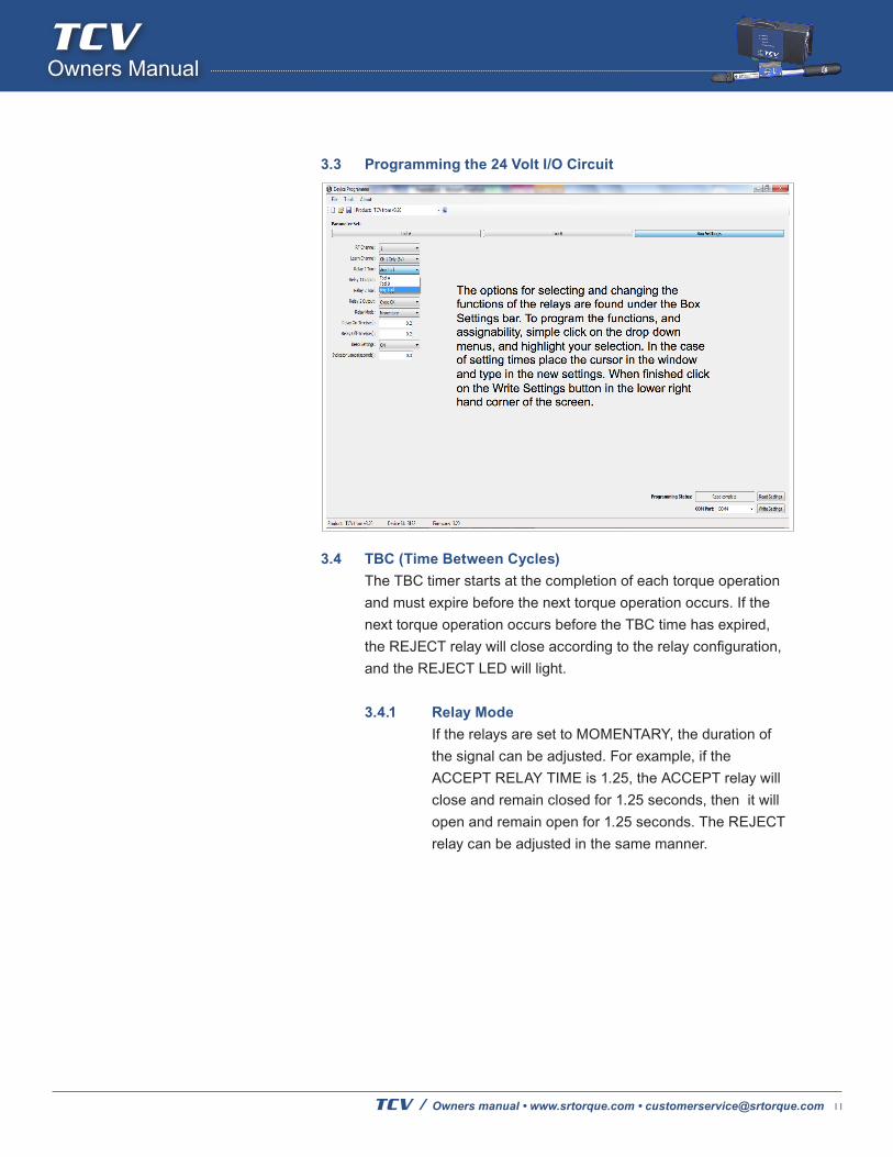
3 Device Programmer 1.3 software ..........................................83.1 Programmable Tool Functions ...............................................93.2 Programmable and Assignable 24 V I/O Relay circuit ...........103.3 Programming the 24 Volt I/O Circuit ......................................113.4 TBC (Time Between Cycles) ..................................................113.4.1 Relay Mode ............................................................................113.4.2 Beeper ...................................................................................123.5 RF Channel ............................................................................133.6 Wrench Radio ID....................................................................13
4 Operation ...............................................................................144.1 Power Up ...............................................................................144.2 Normal Operation ..................................................................144.3 Adding a Wrench or Wrenches ..............................................144.3.1 Changing Channels ...............................................................154.3.1.1 Method 1 For older boards or for mix of new and old ............164.3.1.2 Method 2 For Newest boards only .........................................164.4 LED Functions .......................................................................17
TABLE OF CONTENTSSafety FIRST: To avoid possible injury, always follow these recommended precautions:
• Wear safety glasses or goggles atall times. The TCV and AC Adaptorare for dry location use only.
• Do not stand in water when usingthe TCV or allow the TCV to get wet.
• Be sure torque wrench properlyengages fastener prior toapplying torque.
• Maintain firm footing and balancedbody position when applying torque.
1 IntroductionThe TCV/Switch Wrench System is designed to assist the manufacturer inclosing several loops in the quality system which have been, until now,gaps in their quality improvement efforts. The key capabilities this systemenables are as follows:
1. The ability to integrate hand torque tools into the automated linecontrol system.
2. Process control of the actual torque wrench use process, not just thewrench calibration process.
3. Rapid and effective training in proper torque wrench use, withreinforcement of proper technique provided with every wrench click.This chapter will cover the system, starting with the concepts involvedin the use of the TCV-FM and FM Switch Wrench system.
The TCV-FM works with the FM Switch Wrench to bring systematizedcontrol to the use of manual torque wrenches. The control is applied as follows:
1. The FM Switch Wrench is a preset clicker-type torque wrench. Thetorque is preset using a torque tester to assure the wrench isaccurately set, then the torque setting is locked in.
2. The joint is tested with the FM Switch Wrench and an indicatingtorque wrench to determine the proper duration of a click on the joint.
3. The maximum and minimum duration of a click is programmed intothe TCV-FM.
4. The FM Switch Wrench is used to tighten a fastener. As soon as thewrench clicks, the electronics on the wrench begin to time theduration of the click.
5. When the pressure is released on the wrench, the timer is stoppedand the duration of the click is transmitted to the TCV-FM. The TCVFMcompares the time to the minimum (TMIN) and maximum (TMAX)allowable times for signal duration.
6. The TCV-FM communicates immediately to the operator theacceptability of that use of the wrench. Front panel LED’s and abuzzer inform the operator whether or not the fastener was accepted.
7. The 24 Volt I/O circuit (Input/Output) will report the results of the tool(s) operation. With the TCV the PLC could be used as a part of a SCADA system.
For your safety and the safety of others, read and understand the safety recommendations before installing or operating the TCV.
TCV are designed and constructed to provide the user with a safe and reliable means of calibrating torque wrenches and power tools. Should a fault occur which impairs its function and/or compromises its safe use, immediately disconnect the unit from its power source and secure against unintended operation. Under no circumstances should repair be attempted by persons not qualified in the service of electronic instrumentation. Please contact our customer service department at [email protected] to schedule a return.
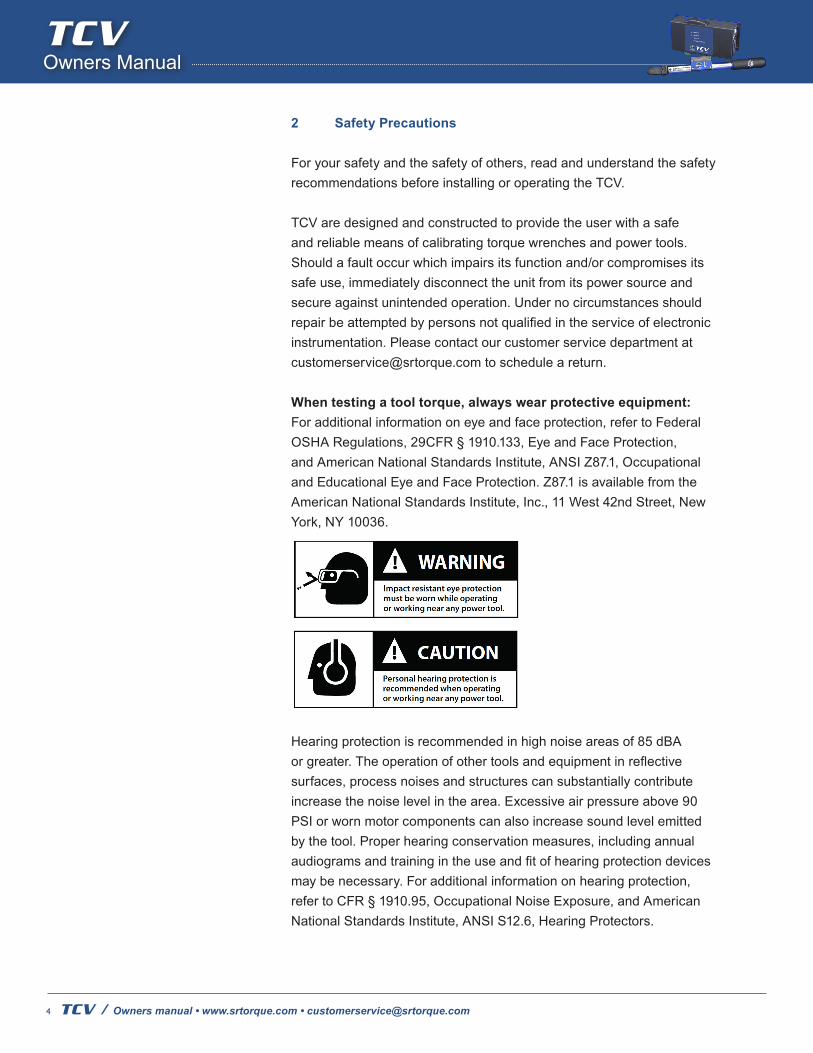
When testing a tool torque, always wear protective equipment: For additional information on eye and face protection, refer to Federal OSHA Regulations, 29CFR § 1910.133, Eye and Face Protection, and American National Standards Institute, ANSI Z87.1, Occupational and Educational Eye and Face Protection. Z87.1 is available from the American National Standards Institute, Inc., 11 West 42nd Street, New York, NY 10036.
Hearing protection is recommended in high noise areas of 85 dBA or greater. The operation of other tools and equipment in reflective surfaces, process noises and structures can substantially contribute increase the noise level in the area. Excessive air pressure above 90 PSI or worn motor components can also increase sound level emitted by the tool. Proper hearing conservation measures, including annual audiograms and training in the use and fit of hearing protection devices may be necessary. For additional information on hearing protection, refer to CFR § 1910.95, Occupational Noise Exposure, and American National Standards Institute, ANSI S12.6, Hearing Protectors.
TCV should be securely mounted and located such that inadvertent movement will not allow the unit to be dislodged, possibly causing personal injury or damage to the unit. Should the unit be dropped,it should be checked by someone qualified in the service ofelectronic instrumentation.
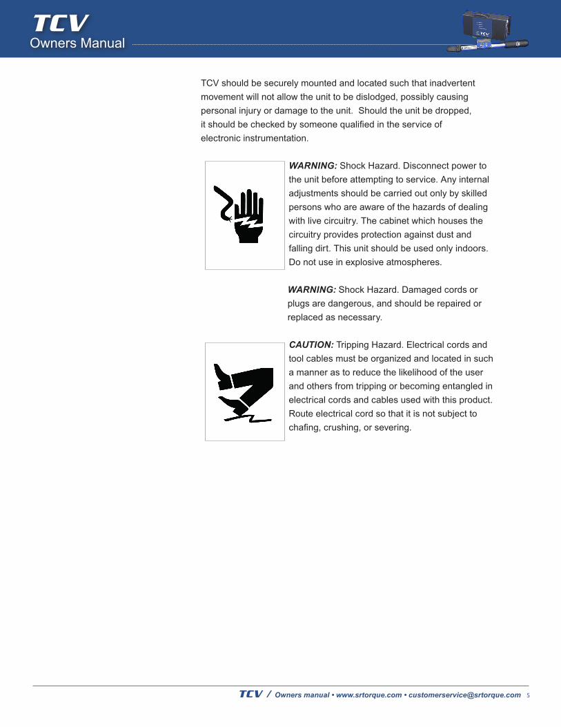
WARNING: Shock Hazard. Disconnect power to the unit before attempting to service. Any internal adjustments should be carried out only by skilled persons who are aware of the hazards of dealing with live circuitry. The cabinet which houses the circuitry provides protection against dust and falling dirt. This unit should be used only indoors. Do not use in explosive atmospheres.
WARNING: Shock Hazard. Damaged cords or plugs are dangerous, and should be repaired or replaced as necessary.
CAUTION: Tripping Hazard. Electrical cords and tool cables must be organized and located in such a manner as to reduce the likelihood of the user and others from tripping or becoming entangled in electrical cords and cables used with this product. Route electrical cord so that it is not subject to chafing, crushing, or severing.
2.1 Warnings The enclosed device complies with Part 15 of the FCC Rules. Operation is subject to the following two conditions: (1) this device may not cause harmful interference and (2) this device must accept any interference received, including interference that may cause undesired operation.
2.1.1 This equipment has been tested and found to comply with the limits for a Class B digital device, pursuant to Part 15 of the FCC Rules.
2.1.2 These limits are designed to provide reasonable protection against harmful interference in a residential installation. This equipment generates, uses and can radiate radio frequency energy and, if not installed and used in accordance with the instructions, may cause harmful interference to radio communications.
2.1.3 However, there is no guarantee that interference will not occur in a particular installation. If this equipment does cause harmful interference to radio or television reception, which can be determined by turning the equipment off and on, the user is encouraged to try to correct the interference by one or more of the following measures: Re-orient or relocate the receiving antenna, Increase the separation between the equipment and receiver.
2.1.4 Connect equipment and receiver to outlets on different circuits.
WARNING: To satisfy FCC RF exposure requirements for mobiletransmitting devices, a separation distance of 20 cm or more should maintained between the antenna of this device and persons during device operation. To ensure compliance, operations at closer than this distance is not recommended. The antenna used for this transmitter must not be co-located in conjunction with any other antenna or transmitter.
2.2 Installation It is mandatory that the national, state, and local safety and wiring standards be followed during installation. These standard would take precedence over any information presented in this section
2.2.1 To avoid the hazard of electrical shock or burn, the following instructions must be adhered to. Failure to follow these instructions may also cause damage to your unit and void existing warranties.
2.2.2 Do not energize the unit until all connections have been properly made. 2.2.3 Equipment must be properly grounded before applying power. Units energized by cord and plug must be connected to an approved and properly grounded receptacle.
2.2.4 Ensure the power switch is in the “off” position before applying power.
2.3 Mounting This unit may be wall mounted, table mounted, beam mounted, suspended overhead, pedestal mounted. Mounting tabs have been provided on the base of this unit. 2.3.1 Locate the unit in a stable, secure area so as to avoid damage to the unit and avoid injury to the operator due to inconvenient mounting. Locate the unit so that ambient air can circulate freely around the box.
The TCV should be located to allow access to the front panel and connectors. The location should allow for unrestricted and comfortable viewing of the front panel. The unit may be remotely mounted, but should still be accessible.
2.4 Source Power CAUTION! This unit is capable of being powered by 115VAC or 230VAC (both 50 and 60Hz). Before powering up the unit for thefirsttime,makesurethevoltageselectiononthepower entry module matches the type of power being applied. The TCV is fused at 1 Amp for 115VAC. The TCV is fused at 1 Amp for 230VAC.
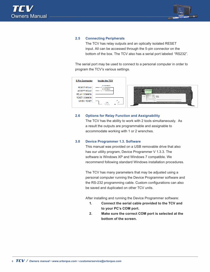
2.5 Connecting Peripherals The TCV has relay outputs and an optically isolated RESET input. All can be accessed through the 5-pin connector on the bottom of the box. The TCV also has a serial port labeled “RS232”.
The serial port may be used to connect to a personal computer in order to program the TCV’s various settings.
2.6 Options for Relay Function and Assignability The TCV has the ability to work with 2 tools simultaneously. As a result the outputs are programmable and assignable to accommodate working with 1 or 2 wrenches.
3.0 Device Programmer 1.3. Software This manual was provided on a USB removable drive that also has our utility program, Device Programmer V 1.3.3. The software is Windows XP and Windows 7 compatible. We recommend following standard Windows installation procedures.
The TCV has many parameters that may be adjusted using a personal computer running the Device Programmer software and the RS-232 programming cable. Custom configurations can also be saved and duplicated on other TCV units.
After installing and running the Device Programmer software: 1. Connect the serial cable provided to the TCV and to your PC’s COM port. 2. MakesurethecorrectCOMportisselectedatthe bottom of the screen.
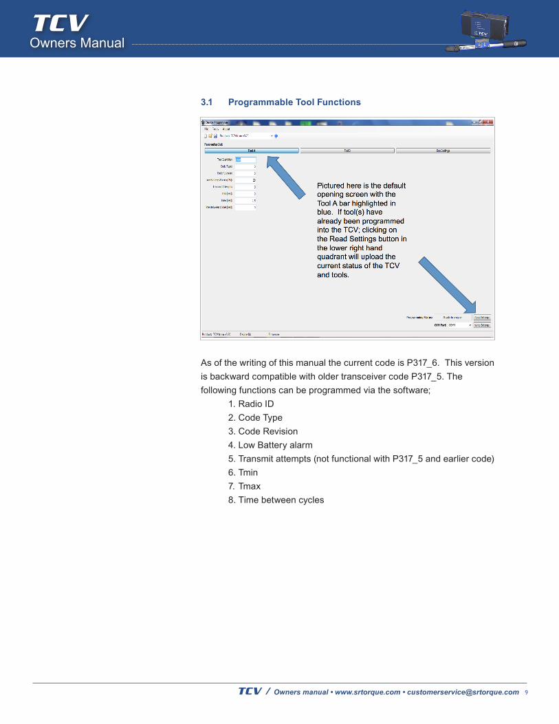
As of the writing of this manual the current code is P317_6. This version is backward compatible with older transceiver code P317_5. The following functions can be programmed via the software; 1. Radio ID 2. Code Type 3. Code Revision 4. Low Battery alarm 5. Transmit attempts (not functional with P317_5 and earlier code) 6. Tmin 7. Tmax 8. Time between cycles
3.2 Programmable and Assignable 24 V I/O Relay circuit The TCV has the ability to work with 2 tools simultaneously. As a result the outputs are programmable and assignable to accommodate working with 1 or 2 wrenches. The following functions can be programmed and assigned for this circuit: 1. Relay output 1 can be assigned for a specific tool (A or B) or assigned to both. 2. Relay output 2 can be assigned for a specific tool (A or B) or assigned to both. 3. Relay outputs functionality can be configured to send a signal for the following events;
a. Cycle OK b. Cycle NOK c. Low battery alert d. TBC* e. None** 4. Relay mode (Latching or Momentary) 5. Relay On Time 6. Relay Off Time 7. Beep Settings (On or Off) 8. Indicator Lamps (Accept or Reject lamps time to be illuminated)
*One purpose of this relay assignation would be to have a light stack notify the operator that the TCV tool communication is suspended.
*For Large multiple installations where the cables can be made the same for any operation.
3.4 TBC (Time Between Cycles) The TBC timer starts at the completion of each torque operation and must expire before the next torque operation occurs. If the next torque operation occurs before the TBC time has expired, the REJECT relay will close according to the relay configuration, and the REJECT LED will light.
3.4.1 Relay Mode If the relays are set to MOMENTARY, the duration of the signal can be adjusted. For example, if the ACCEPT RELAY TIME is 1.25, the ACCEPT relay will close and remain closed for 1.25 seconds, then it will open and remain open for 1.25 seconds. The REJECT relay can be adjusted in the same manner.
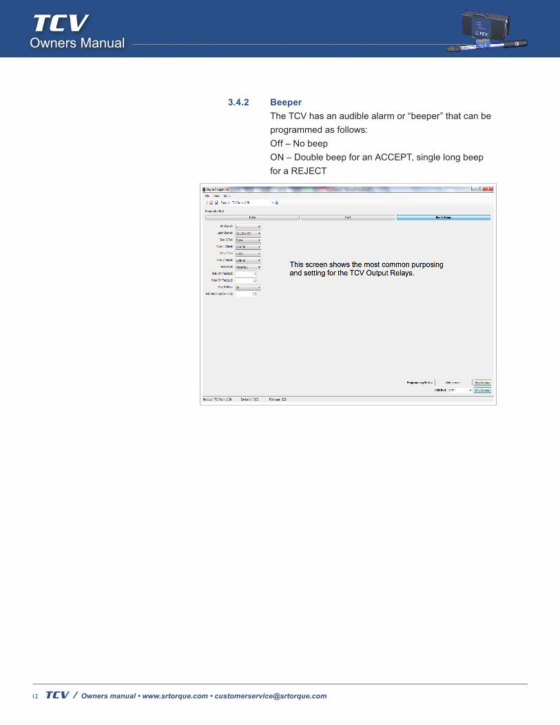
3.4.2 Beeper The TCV has an audible alarm or “beeper” that can be programmed as follows: Off – No beep ON – Double beep for an ACCEPT, single long beep for a REJECT
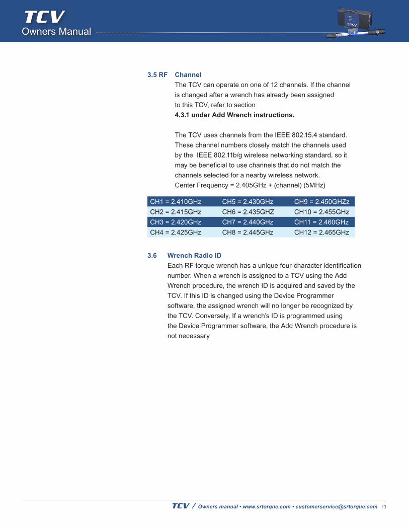
3.5 RF Channel The TCV can operate on one of 12 channels. If the channel is changed after a wrench has already been assigned to this TCV, refer to section 4.3.1 under Add Wrench instructions.
The TCV uses channels from the IEEE 802.15.4 standard. These channel numbers closely match the channels used by the IEEE 802.11b/g wireless networking standard, so it may be beneficial to use channels that do not match the channels selected for a nearby wireless network. Center Frequency = 2.405GHz + (channel) (5MHz)
3.6 Wrench Radio ID Each RF torque wrench has a unique four-character identification number. When a wrench is assigned to a TCV using the Add Wrench procedure, the wrench ID is acquired and saved by the TCV. If this ID is changed using the Device Programmer software, the assigned wrench will no longer be recognized by the TCV. Conversely, If a wrench’s ID is programmed using the Device Programmer software, the Add Wrench procedure is not necessary
4.1 Power Up During power up, all four LEDs will illuminate and a triple beep will sound. After the triple beep has sounded, the TCV will be ready for operation.
4.2 Normal Operation During operation, the TCV will indicate the status of each fastening cycle. If the cycle was within the user-defined limits, an ACCEPT status will be issued, the ACCEPT LED will illuminate, and the ACCEPT relay will close if so programmed.
4.2.1 If the fastening cycle did not conform to the user defined limits, the REJECT LED will illuminate and the REJECT relay will close if so programmed.
4.2.2 The status of the last fastening cycle persists until the next cycle, the time set for illumination has expired or the status may be cleared at any time using the RESET input.
4.3 Adding a Wrench or Wrenches Before a wrench can be used with the TCV, it must first be identified by the TCV. To do this, turn the key on the TCV to the “PROG” position, then click the wrench. If the ACCEPT LED turns on, the operation was successful.
4.3.1 If two tools are to be used with the TCV they both must be identified by the TCV at the same time. Turn the key back to the “LOCK” position. The TCV will now respond only to the wrench(es) that it has identified. 4.3.2 It is important to understand that when programming multiple wrenches the first tool clicked will be identified by Device Programmer as Tool A and the second tool to be clicked will be identified as Tool B.
4.3.3 Note: Each wrench also stores the identification number (ID) of the TCV to which it is assigned. In order to assign a wrench to a TCV, any stored ID must be cleared from the wrench. To do this, click and hold the wrench until the LED flashes to indicate a reset (about 5 seconds). The wrench will now be set to perform an inquiry for available TCVs. Immediately after a battery is installed on the wrench, the LED will alternate between red and green several times very quickly. This indicates a reset condition. This reset indication will be followed by a red pulse if the wrench has no stored ID and is ready to be added to a TCV. If the reset indication is followed by a green pulse, the wrench has already been assigned to a TCV and is ready to perform torque operations. An alternate way to add a wrench to the TCV is to program the wrench’s radio ID using the Device Programmer software.
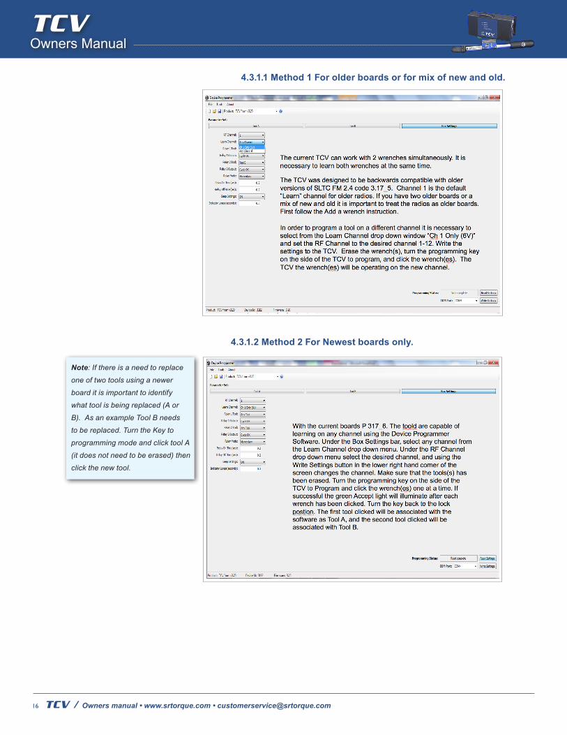
4.3.1 Changing Channels To change channels it is necessary to use Device Programmer software. Since the TCV is backwards compatible with older transceivers there are two methods for changing channels.
POWER – The POWER LED flashes on and off with a two-second period (one second on, one second off) to indicate that the TCV is powered up and the processor is functioning.
ACCEPT – The ACCEPT LED will illuminate after each torque that results in an “OK” status.
REJECT – The REJECT LED will illuminate after each torque that violates the Tmin or Tmax values. A Time Between Cycles (TBC) violation will also cause the REJECT LED to illuminate.
STRENGTH/PROG - After each torque operation, the STRENGTH/PROG LED will turn on for 2 seconds to indicate the received signal strength from the wrench transmitter. Green indicates a good signal. Yellow indicates a moderate signal. Red indicates a poor signal. The STRENGTH/PROG LED will continue to flash red after each cycle until the Time Between Cycles (TBC) has expired to indicate to the operator that a torque operation is not permitted at this time. The next torque operation will be permitted when the STRENGTH/PROG LED stops flashing red. The STRENGTH/PROG LED stays solid red as long as the key is in the “PROG” position.
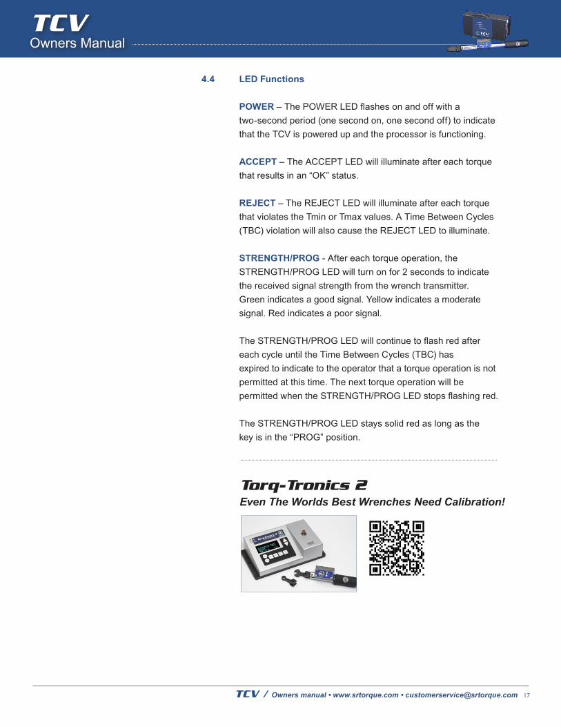
Torq-Tronics 2 Even The Worlds Best Wrenches Need Calibration!