1.1 Reliable solution for the water and wastewater industry ............................................... 31.2 Options.............................................................................................................................. 51.3 Measuring principle.......................................................................................................... 8
3.1 Intended use ................................................................................................................... 283.2 General notes on installation ......................................................................................... 28
3.2.1 Vibration ................................................................................................................................ 283.2.2 Magnetic field........................................................................................................................ 28
3.3 Installation conditions .................................................................................................... 293.3.1 Inlet and outlet ...................................................................................................................... 293.3.2 Bends in 2 or 3 dimensions................................................................................................... 293.3.3 T-section ............................................................................................................................... 303.3.4 Bends .................................................................................................................................... 303.3.5 Open feed or discharge......................................................................................................... 313.3.6 Flange deviation .................................................................................................................... 313.3.7 Pump ..................................................................................................................................... 313.3.8 Control valve ......................................................................................................................... 323.3.9 Air venting and vacuum forces ............................................................................................. 323.3.10 Mounting position................................................................................................................ 33
3.4 Mounting ......................................................................................................................... 343.4.1 Torques and pressures......................................................................................................... 34
4 Electrical connections 37
4.1 Safety instructions.......................................................................................................... 374.2 Grounding ....................................................................................................................... 374.3 Virtual reference for IFC 300 (C, W and F version) ....................................................... 394.4 Connection diagrams ..................................................................................................... 39
PRODUCT FEATURES 1
3
OPTIFLUX 2000
www.krohne.com11/2017 - 4000086806 - TD OPTIFLUX 2000 R10 en
1.1 Reliable solution for the water and wastewater industry
The OPTIFLUX 2000OPTIFLUX 2000OPTIFLUX 2000OPTIFLUX 2000 is designed to meet the demands for all water and waste water applications including groundwater, potable water, waste water, sludge and sewage, industry water and salt water.
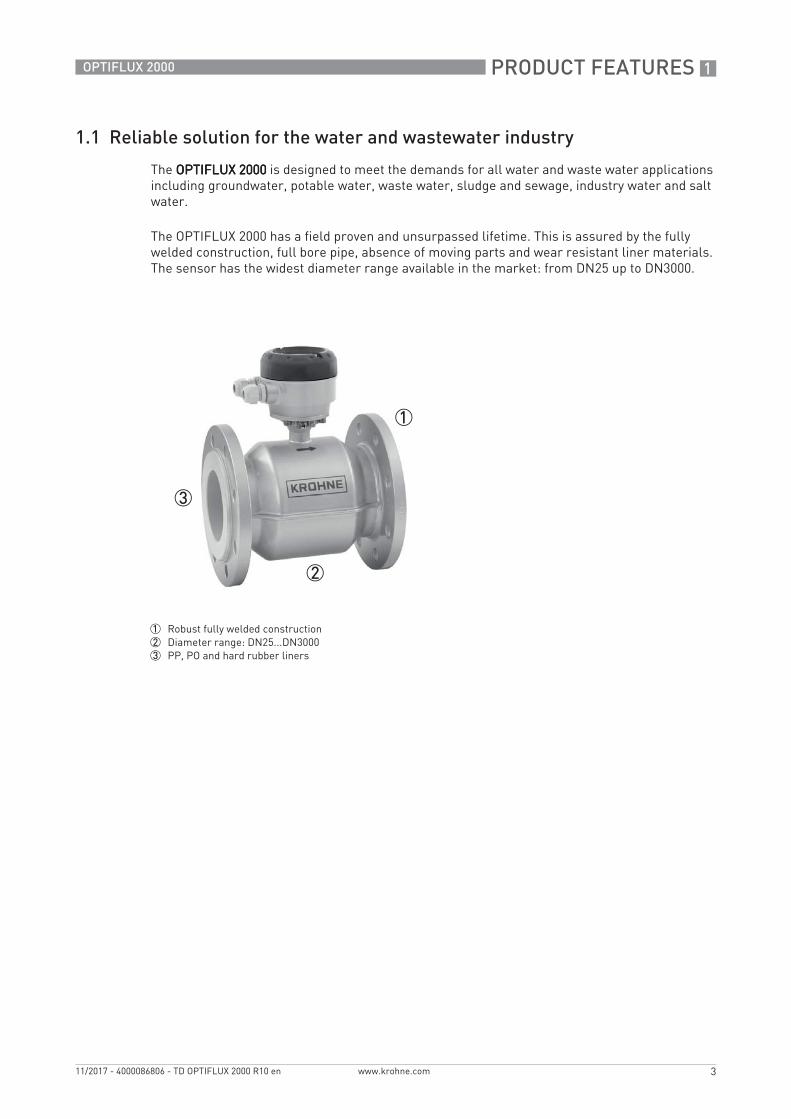
The OPTIFLUX 2000 has a field proven and unsurpassed lifetime. This is assured by the fully welded construction, full bore pipe, absence of moving parts and wear resistant liner materials. The sensor has the widest diameter range available in the market: from DN25 up to DN3000.
1 Robust fully welded construction2 Diameter range: DN25...DN30003 PP, PO and hard rubber liners
1 PRODUCT FEATURES
4
OPTIFLUX 2000
www.krohne.com 11/2017 - 4000086806 - TD OPTIFLUX 2000 R10 en
Highlights• Rugged liners suitable for any water and wastewater application• Proven and unsurpassed lifetime, huge installed base• Tamper proof, fully welded construction, also available in customer specific constructions• Drinking water approvals including KTW, KIWA, ACS, DVGW, NSF, WRAS• Suitable for subsoil installation and constant flooding (IP68)• Bi-directional flow metering• Compliant with requirements for custody transfer
(MID MI-001, OIML R49, ISO 4064, EN 14154)• Standard in house wet calibration of sensors up to diameter DN3000• Easy installation and commissioning• No grounding rings with virtual reference option on IFC 300• In-situ verification with OPTICHECK• Extensive diagnostic capabilities• Maintenance-free
Applications• Water abstraction• Water purification and desalination• Drinking water distribution networks• Revenue metering or billing• Leakage detection• Irrigation• Industry water• Cooling water• Wastewater• Sewage and sludge• Sea water
PRODUCT FEATURES 1
5
OPTIFLUX 2000
www.krohne.com11/2017 - 4000086806 - TD OPTIFLUX 2000 R10 en
1.2 Options
The reliable solution for the water and wastewater industry
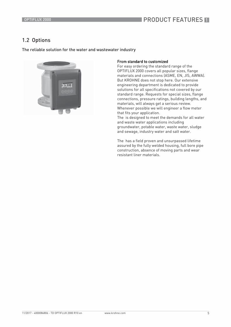
From standard to customizedFrom standard to customizedFrom standard to customizedFrom standard to customizedFor easy ordering the standard range of the OPTIFLUX 2000 covers all popular sizes, flange materials and connections (ASME, EN, JIS, AWWA).But KROHNE does not stop here. Our extensive engineering department is dedicated to provide solutions for all specifications not covered by our standard range. Requests for special sizes, flange connections, pressure ratings, building lengths, and materials, will always get a serious review. Whenever possible we will engineer a flow meter that fits your application.The is designed to meet the demands for all water and waste water applications including groundwater, potable water, waste water, sludge and sewage, industry water and salt water.
The has a field proven and unsurpassed lifetime assured by the fully welded housing, full bore pipe construction, absence of moving parts and wear resistant liner materials.
1 PRODUCT FEATURES
6
OPTIFLUX 2000
www.krohne.com 11/2017 - 4000086806 - TD OPTIFLUX 2000 R10 en
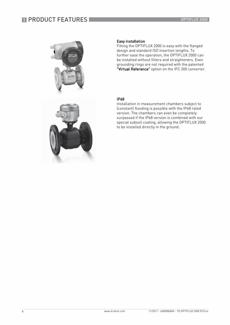
Easy installationEasy installationEasy installationEasy installationFitting the OPTIFLUX 2000 is easy with the flanged design and standard ISO insertion lengths. To further ease the operation, the OPTIFLUX 2000 can be installed without filters and straighteners. Even grounding rings are not required with the patented "Virtual Reference""Virtual Reference""Virtual Reference""Virtual Reference" option on the IFC 300 converter.
IP68IP68IP68IP68Installation in measurement chambers subject to (constant) flooding is possible with the IP68 rated version. The chambers can even be completely surpassed if the IP68 version is combined with our special subsoil coating, allowing the OPTIFLUX 2000 to be installed directly in the ground.
PRODUCT FEATURES 1
7
OPTIFLUX 2000
www.krohne.com11/2017 - 4000086806 - TD OPTIFLUX 2000 R10 en
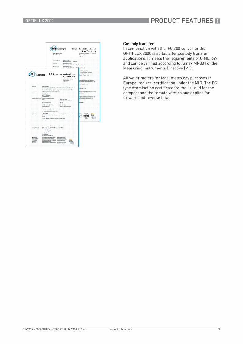
Custody transferCustody transferCustody transferCustody transferIn combination with the IFC 300 converter the OPTIFLUX 2000 is suitable for custody transfer applications. It meets the requirements of OIML R49 and can be verified according to Annex MI-001 of the Measuring Instruments Directive (MID)
All water meters for legal metrology purposes in Europe require certification under the MID. The EC type examination certificate for the is valid for the compact and the remote version and applies for forward and reverse flow.
1 PRODUCT FEATURES
8
OPTIFLUX 2000
www.krohne.com 11/2017 - 4000086806 - TD OPTIFLUX 2000 R10 en
1.3 Measuring principle
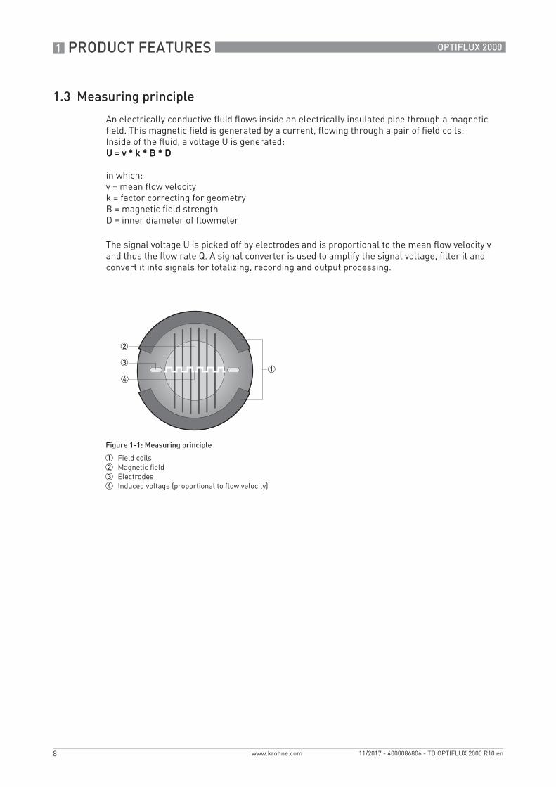
An electrically conductive fluid flows inside an electrically insulated pipe through a magnetic field. This magnetic field is generated by a current, flowing through a pair of field coils.Inside of the fluid, a voltage U is generated:U = v * k * B * DU = v * k * B * DU = v * k * B * DU = v * k * B * D
in which:v = mean flow velocityk = factor correcting for geometryB = magnetic field strengthD = inner diameter of flowmeter
The signal voltage U is picked off by electrodes and is proportional to the mean flow velocity v and thus the flow rate Q. A signal converter is used to amplify the signal voltage, filter it and convert it into signals for totalizing, recording and output processing.
Figure 1-1: Measuring principle
1 Field coils2 Magnetic field3 Electrodes4 Induced voltage (proportional to flow velocity)
TECHNICAL DATA 2
9
OPTIFLUX 2000
www.krohne.com11/2017 - 4000086806 - TD OPTIFLUX 2000 R10 en
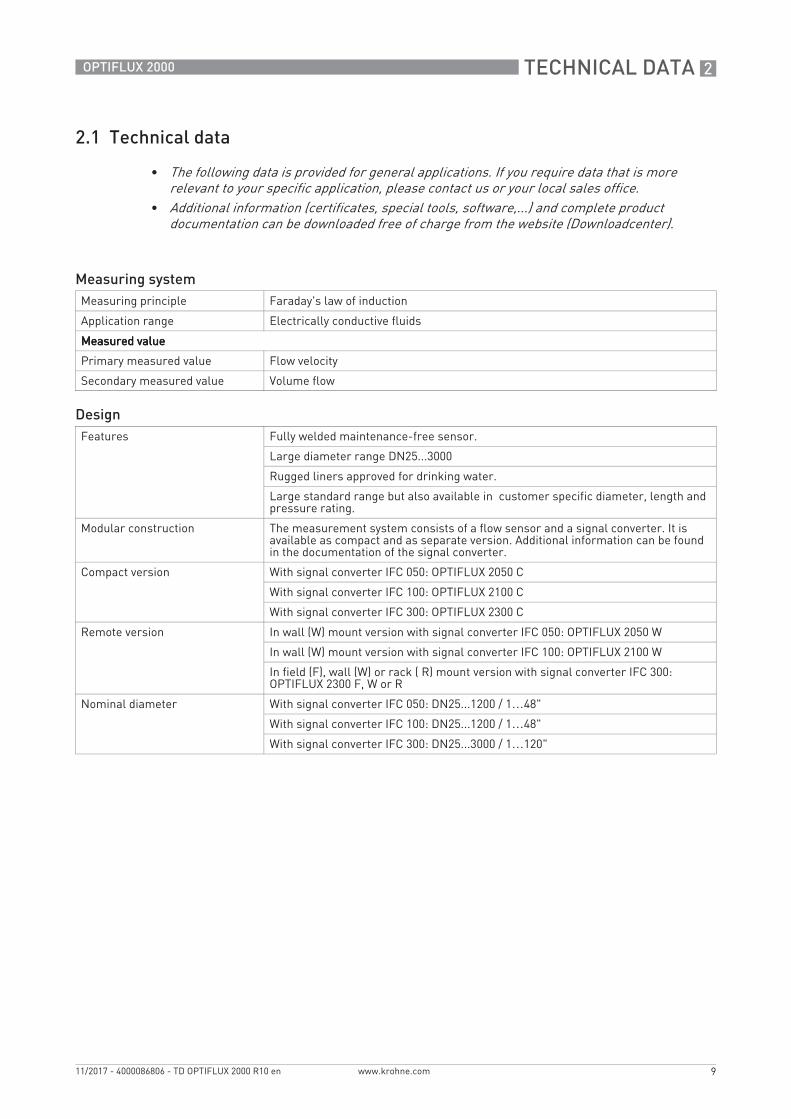
2.1 Technical data
• The following data is provided for general applications. If you require data that is more relevant to your specific application, please contact us or your local sales office.
• Additional information (certificates, special tools, software,...) and complete product documentation can be downloaded free of charge from the website (Downloadcenter).
Measuring systemMeasuring principle Faraday's law of induction
Application range Electrically conductive fluids
Measured valueMeasured valueMeasured valueMeasured value
Large standard range but also available in customer specific diameter, length and pressure rating.
Modular construction The measurement system consists of a flow sensor and a signal converter. It is available as compact and as separate version. Additional information can be found in the documentation of the signal converter.
Compact version With signal converter IFC 050: OPTIFLUX 2050 C
With signal converter IFC 100: OPTIFLUX 2100 C
With signal converter IFC 300: OPTIFLUX 2300 C
Remote version In wall (W) mount version with signal converter IFC 050: OPTIFLUX 2050 W
In wall (W) mount version with signal converter IFC 100: OPTIFLUX 2100 W
In field (F), wall (W) or rack ( R) mount version with signal converter IFC 300: OPTIFLUX 2300 F, W or R
Nominal diameter With signal converter IFC 050: DN25...1200 / 1…48"
With signal converter IFC 100: DN25...1200 / 1…48"
With signal converter IFC 300: DN25...3000 / 1…120"
2 TECHNICAL DATA
10
OPTIFLUX 2000
www.krohne.com 11/2017 - 4000086806 - TD OPTIFLUX 2000 R10 en
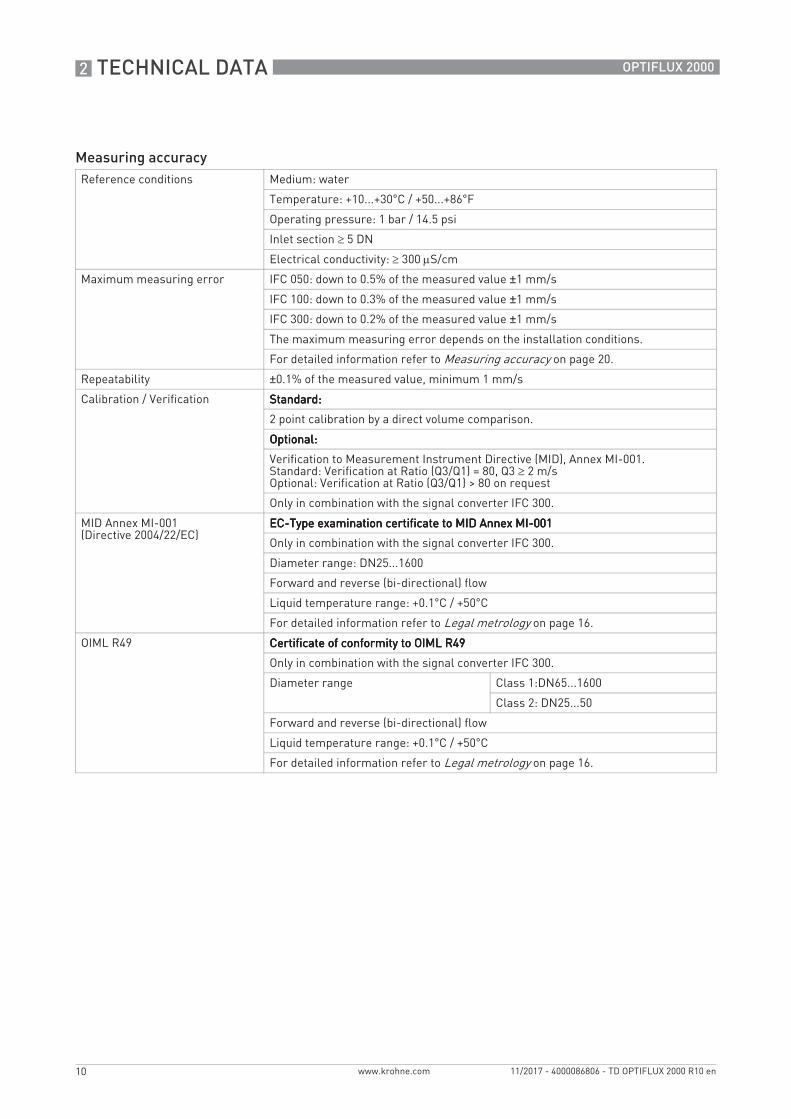
Measuring accuracyReference conditions Medium: water
Temperature: +10...+30°C / +50...+86°F
Operating pressure: 1 bar / 14.5 psi
Inlet section 5 DN
Electrical conductivity: 300 S/cm
Maximum measuring error IFC 050: down to 0.5% of the measured value ±1 mm/s
IFC 100: down to 0.3% of the measured value ±1 mm/s
IFC 300: down to 0.2% of the measured value ±1 mm/s
The maximum measuring error depends on the installation conditions.
For detailed information refer to Measuring accuracy on page 20.
Repeatability ±0.1% of the measured value, minimum 1 mm/s
2 point calibration by a direct volume comparison.
Optional:Optional:Optional:Optional:
Verification to Measurement Instrument Directive (MID), Annex MI-001.Standard: Verification at Ratio (Q3/Q1) = 80, Q3 2 m/sOptional: Verification at Ratio (Q3/Q1) > 80 on request
Only in combination with the signal converter IFC 300.
MID Annex MI-001(Directive 2004/22/EC)
EC-Type examination certificate to MID Annex MI-001EC-Type examination certificate to MID Annex MI-001EC-Type examination certificate to MID Annex MI-001EC-Type examination certificate to MID Annex MI-001
Only in combination with the signal converter IFC 300.
Diameter range: DN25...1600
Forward and reverse (bi-directional) flow
Liquid temperature range: +0.1°C / +50°C
For detailed information refer to Legal metrology on page 16.
OIML R49 Certificate of conformity to OIML R49Certificate of conformity to OIML R49Certificate of conformity to OIML R49Certificate of conformity to OIML R49
Only in combination with the signal converter IFC 300.
Diameter range Class 1:DN65...1600
Class 2: DN25...50
Forward and reverse (bi-directional) flow
Liquid temperature range: +0.1°C / +50°C
For detailed information refer to Legal metrology on page 16.
TECHNICAL DATA 2
11
OPTIFLUX 2000
www.krohne.com11/2017 - 4000086806 - TD OPTIFLUX 2000 R10 en
www.krohne.com11/2017 - 4000086806 - TD OPTIFLUX 2000 R10 en
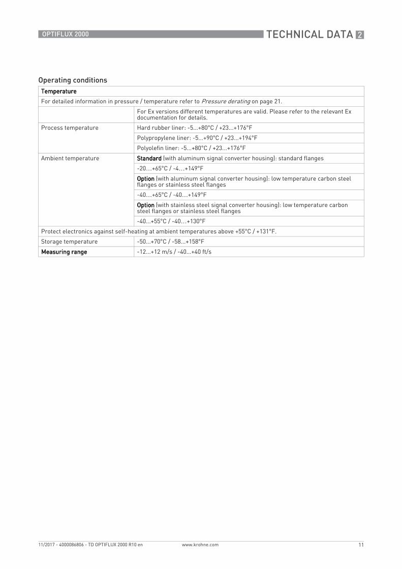
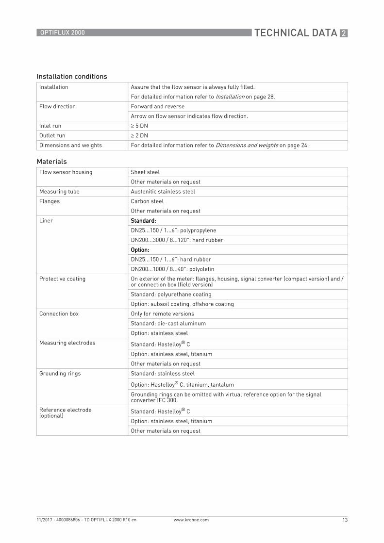
Installation conditionsInstallation Assure that the flow sensor is always fully filled.
For detailed information refer to Installation on page 28.
Flow direction Forward and reverse
Arrow on flow sensor indicates flow direction.
Inlet run 5 DN
Outlet run 2 DN
Dimensions and weights For detailed information refer to Dimensions and weights on page 24.
MaterialsFlow sensor housing Sheet steel
Other materials on request
Measuring tube Austenitic stainless steel
Flanges Carbon steel
Other materials on request
Liner Standard:Standard:Standard:Standard:
DN25...150 / 1...6": polypropylene
DN200...3000 / 8...120": hard rubber
Option:Option:Option:Option:
DN25...150 / 1...6": hard rubber
DN200...1000 / 8...40": polyolefin
Protective coating On exterior of the meter: flanges, housing, signal converter (compact version) and / or connection box (field version)
Standard: polyurethane coating
Option: subsoil coating, offshore coating
Connection box Only for remote versions
Standard: die-cast aluminum
Option: stainless steel
Measuring electrodes Standard: Hastelloy® C
Option: stainless steel, titanium
Other materials on request
Grounding rings Standard: stainless steel
Option: Hastelloy® C, titanium, tantalum
Grounding rings can be omitted with virtual reference option for the signal converter IFC 300.
Reference electrode (optional)
Standard: Hastelloy® C
Option: stainless steel, titanium
Other materials on request
2 TECHNICAL DATA
14
OPTIFLUX 2000
www.krohne.com 11/2017 - 4000086806 - TD OPTIFLUX 2000 R10 en
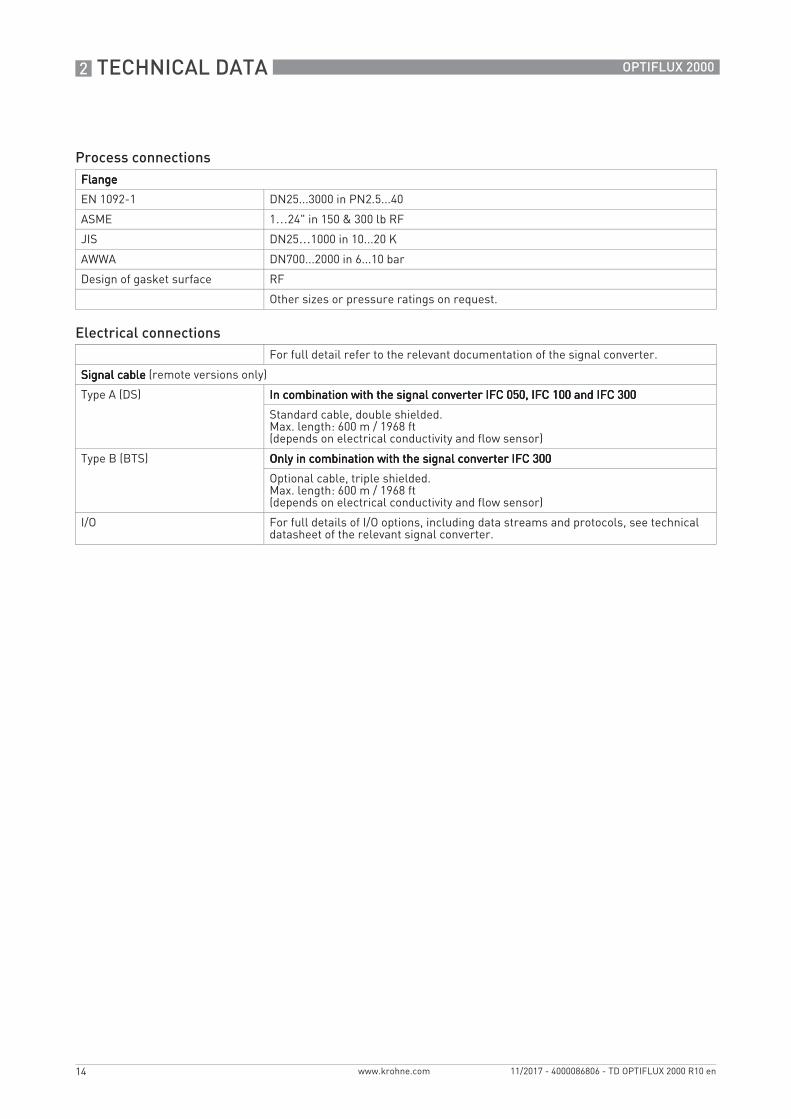
Process connectionsFlangeFlangeFlangeFlange
EN 1092-1 DN25...3000 in PN2.5...40
ASME 1…24" in 150 & 300 lb RF
JIS DN25…1000 in 10...20 K
AWWA DN700...2000 in 6...10 bar
Design of gasket surface RF
Other sizes or pressure ratings on request.
Electrical connectionsFor full detail refer to the relevant documentation of the signal converter.
Signal cableSignal cableSignal cableSignal cable (remote versions only)
Type A (DS) In combination with the signal converter IFC 050, IFC 100 and IFC 300In combination with the signal converter IFC 050, IFC 100 and IFC 300In combination with the signal converter IFC 050, IFC 100 and IFC 300In combination with the signal converter IFC 050, IFC 100 and IFC 300
Standard cable, double shielded.Max. length: 600 m / 1968 ft(depends on electrical conductivity and flow sensor)
Type B (BTS) Only in combination with the signal converter IFC 300Only in combination with the signal converter IFC 300Only in combination with the signal converter IFC 300Only in combination with the signal converter IFC 300
Optional cable, triple shielded.Max. length: 600 m / 1968 ft(depends on electrical conductivity and flow sensor)
I/O For full details of I/O options, including data streams and protocols, see technical datasheet of the relevant signal converter.
TECHNICAL DATA 2
15
OPTIFLUX 2000
www.krohne.com11/2017 - 4000086806 - TD OPTIFLUX 2000 R10 en
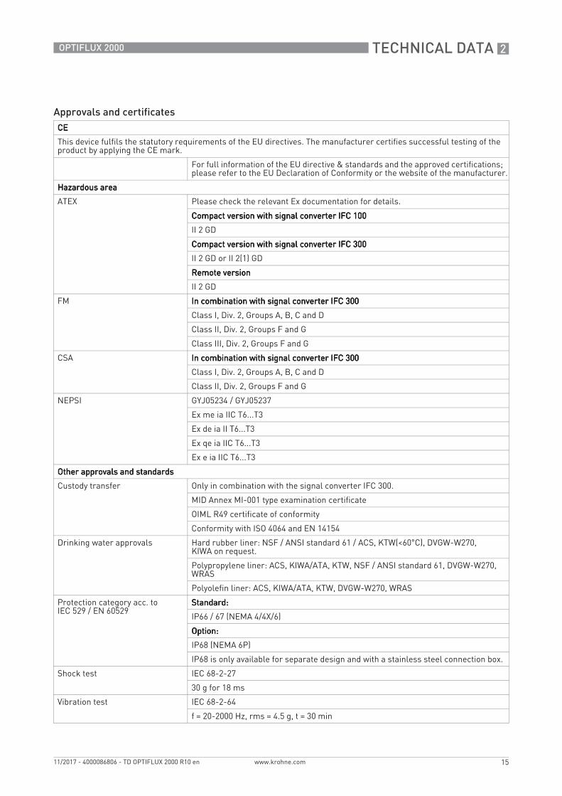
Approvals and certificatesCECECECE
This device fulfils the statutory requirements of the EU directives. The manufacturer certifies successful testing of the product by applying the CE mark.
For full information of the EU directive & standards and the approved certifications; please refer to the or the website of the manufacturer.
Hazardous areaHazardous areaHazardous areaHazardous area
ATEX Please check the relevant Ex documentation for details.
Compact version with signal converter IFC 100Compact version with signal converter IFC 100Compact version with signal converter IFC 100Compact version with signal converter IFC 100
II 2 GD
Compact version with signal converter IFC 300Compact version with signal converter IFC 300Compact version with signal converter IFC 300Compact version with signal converter IFC 300
II 2 GD or II 2(1) GD
Remote versionRemote versionRemote versionRemote version
II 2 GD
FM In combination with signal converter IFC 300In combination with signal converter IFC 300In combination with signal converter IFC 300In combination with signal converter IFC 300
Class I, Div. 2, Groups A, B, C and D
Class II, Div. 2, Groups F and G
Class III, Div. 2, Groups F and G
CSA In combination with signal converter IFC 300In combination with signal converter IFC 300In combination with signal converter IFC 300In combination with signal converter IFC 300
Class I, Div. 2, Groups A, B, C and D
Class II, Div. 2, Groups F and G
NEPSI GYJ05234 / GYJ05237
Ex me ia IIC T6...T3
Ex de ia II T6...T3
Ex qe ia IIC T6...T3
Ex e ia IIC T6...T3
Other approvals and standardsOther approvals and standardsOther approvals and standardsOther approvals and standards
Custody transfer Only in combination with the signal converter IFC 300.
MID Annex MI-001 type examination certificate
OIML R49 certificate of conformity
Conformity with ISO 4064 and EN 14154
Drinking water approvals Hard rubber liner: NSF / ANSI standard 61 / ACS, KTW(<60°C), DVGW-W270,KIWA on request.
IP68 is only available for separate design and with a stainless steel connection box.
Shock test IEC 68-2-27
30 g for 18 ms
Vibration test IEC 68-2-64
f = 20-2000 Hz, rms = 4.5 g, t = 30 min
2 TECHNICAL DATA
16
OPTIFLUX 2000
www.krohne.com 11/2017 - 4000086806 - TD OPTIFLUX 2000 R10 en
2.2 Legal metrology
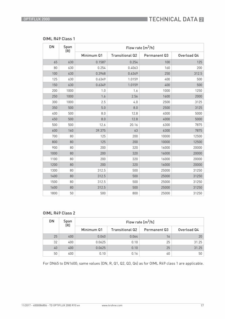
2.2.1 OIML R49
The has a certificate of conformity with the international recommendation OIML R49 (edition 2006). The certificate has been issued by NMi (Dutch board of weight and measures). The OIML R49 recommendation (2006) concerns water meters intended for the metering of cold potable and hot water. The measuring range of the is determined by Q3 (nominal flow rate) and R (ratio).
The OPTIFLUX 2300 meets the requirements for water meters of accuracy class 1 and 2.
• For accuracy class 1, the maximum permissible error for water meters is ±1% for the upper flow rate zone and ±3% for the lower flow rate zones.
• For accuracy class 2, the maximum permissible error for water meters is ±2% for the upper flow rate zone and ±5% for the lower flow rate zones.
According to OIML R49, accuracy class 1 designation shall be applied only to flowmeter with Q3 100 m3/h.
OIML R49 and MID Annex MI-001 is onlyonlyonlyonly available in combination with the signal converter IFC 300!
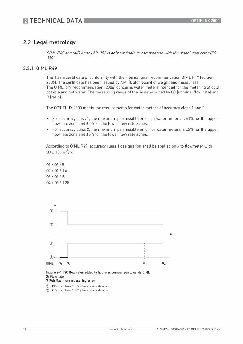
Q1 = Q3 / R
Q2 = Q1 * 1.6
Q3 = Q1 * R
Q4 = Q3 * 1.25
Figure 2-1: ISO flow rates added to figure as comparison towards OIMLX:X:X:X: Flow rateY [%]:Y [%]:Y [%]:Y [%]: Maximum measuring error
1 ±3% for class 1, ±5% for class 2 devices2 ±1% for class 1, ±2% for class 2 devices
TECHNICAL DATA 2
17
OPTIFLUX 2000
www.krohne.com11/2017 - 4000086806 - TD OPTIFLUX 2000 R10 en
OIML R49 Class 1
OIML R49 Class 2
For DN65 to DN1600; same values (DN, R, Q1, Q2, Q3, Q4) as for OIML R49 class 1 are applicable.
www.krohne.com 11/2017 - 4000086806 - TD OPTIFLUX 2000 R10 en
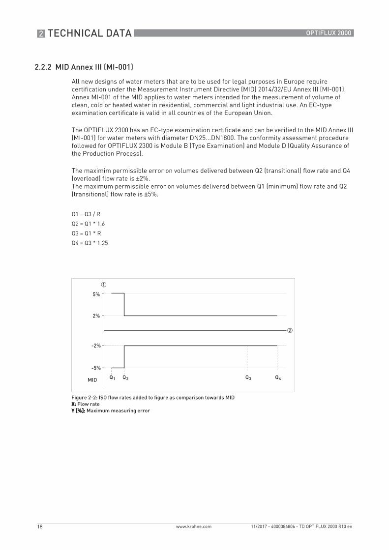
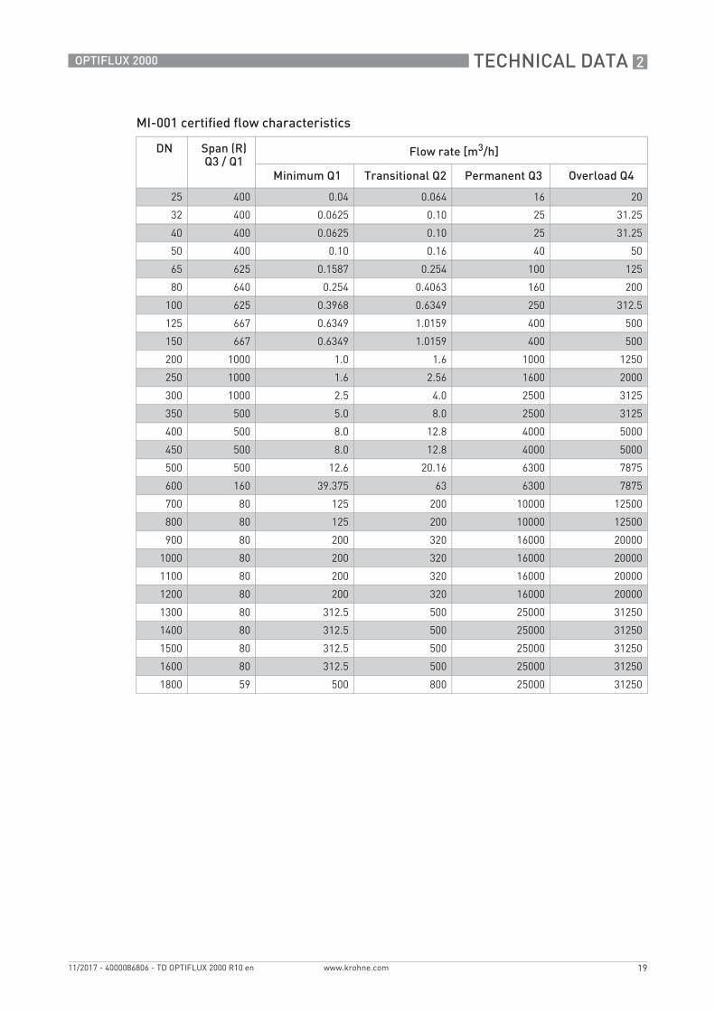
2.2.2 MID Annex III (MI-001)
All new designs of water meters that are to be used for legal purposes in Europe require certification under the Measurement Instrument Directive (MID) 2014/32/EU Annex III (MI-001).Annex MI-001 of the MID applies to water meters intended for the measurement of volume of clean, cold or heated water in residential, commercial and light industrial use. An EC-type examination certificate is valid in all countries of the European Union.
The OPTIFLUX 2300 has an EC-type examination certificate and can be verified to the MID Annex III (MI-001) for water meters with diameter DN25...DN1800. The conformity assessment procedure followed for OPTIFLUX 2300 is Module B (Type Examination) and Module D (Quality Assurance of the Production Process).
The maximim permissible error on volumes delivered between Q2 (transitional) flow rate and Q4 (overload) flow rate is ±2%.The maximum permissible error on volumes delivered between Q1 (minimum) flow rate and Q2 (transitional) flow rate is ±5%.
Q1 = Q3 / R
Q2 = Q1 * 1.6
Q3 = Q1 * R
Q4 = Q3 * 1.25
Figure 2-2: ISO flow rates added to figure as comparison towards MIDX:X:X:X: Flow rateY [%]:Y [%]:Y [%]:Y [%]: Maximum measuring error
TECHNICAL DATA 2
19
OPTIFLUX 2000
www.krohne.com11/2017 - 4000086806 - TD OPTIFLUX 2000 R10 en
www.krohne.com 11/2017 - 4000086806 - TD OPTIFLUX 2000 R10 en
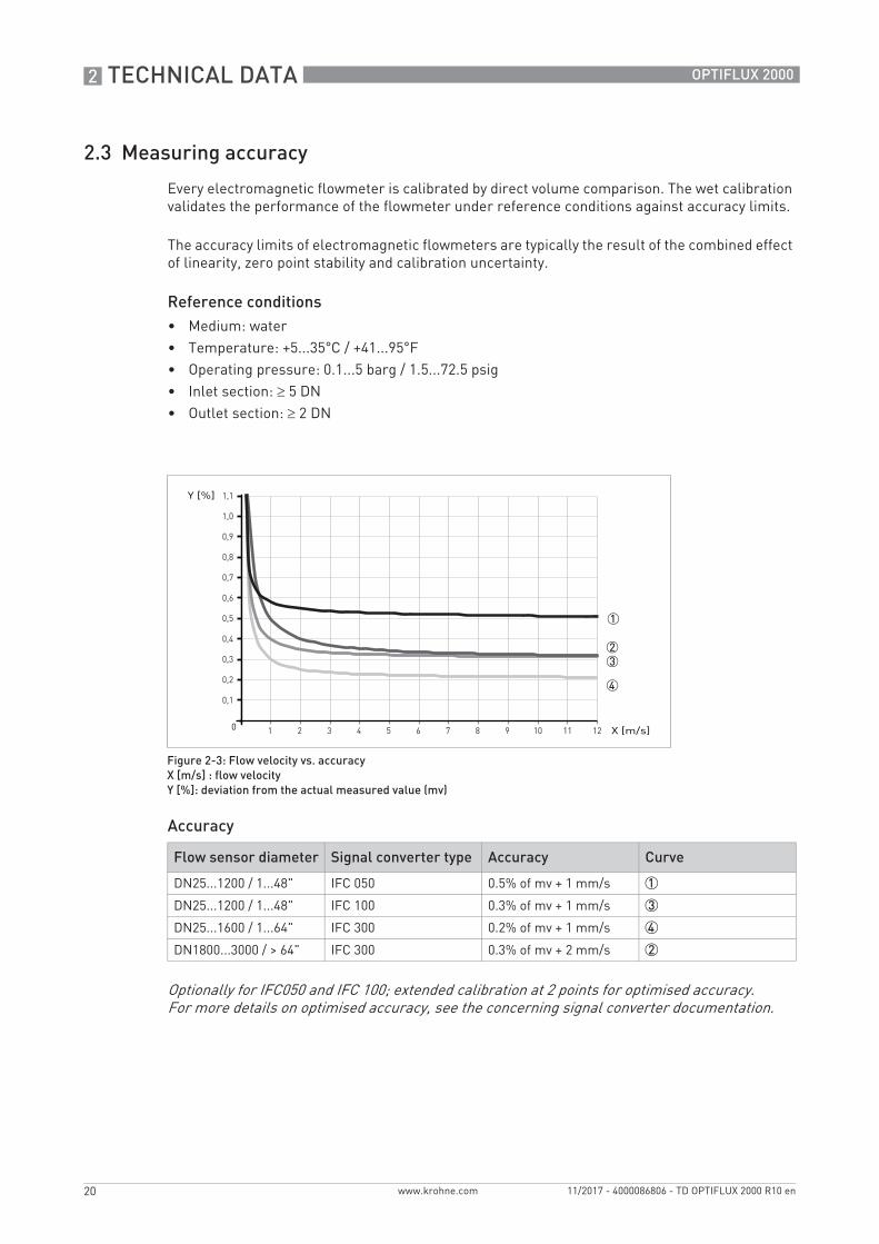
2.3 Measuring accuracy
Every electromagnetic flowmeter is calibrated by direct volume comparison. The wet calibration validates the performance of the flowmeter under reference conditions against accuracy limits.
The accuracy limits of electromagnetic flowmeters are typically the result of the combined effect of linearity, zero point stability and calibration uncertainty.
Optionally for IFC050 and IFC 100; extended calibration at 2 points for optimised accuracy.For more details on optimised accuracy, see the concerning signal converter documentation.
TECHNICAL DATA 2
21
OPTIFLUX 2000
www.krohne.com11/2017 - 4000086806 - TD OPTIFLUX 2000 R10 en
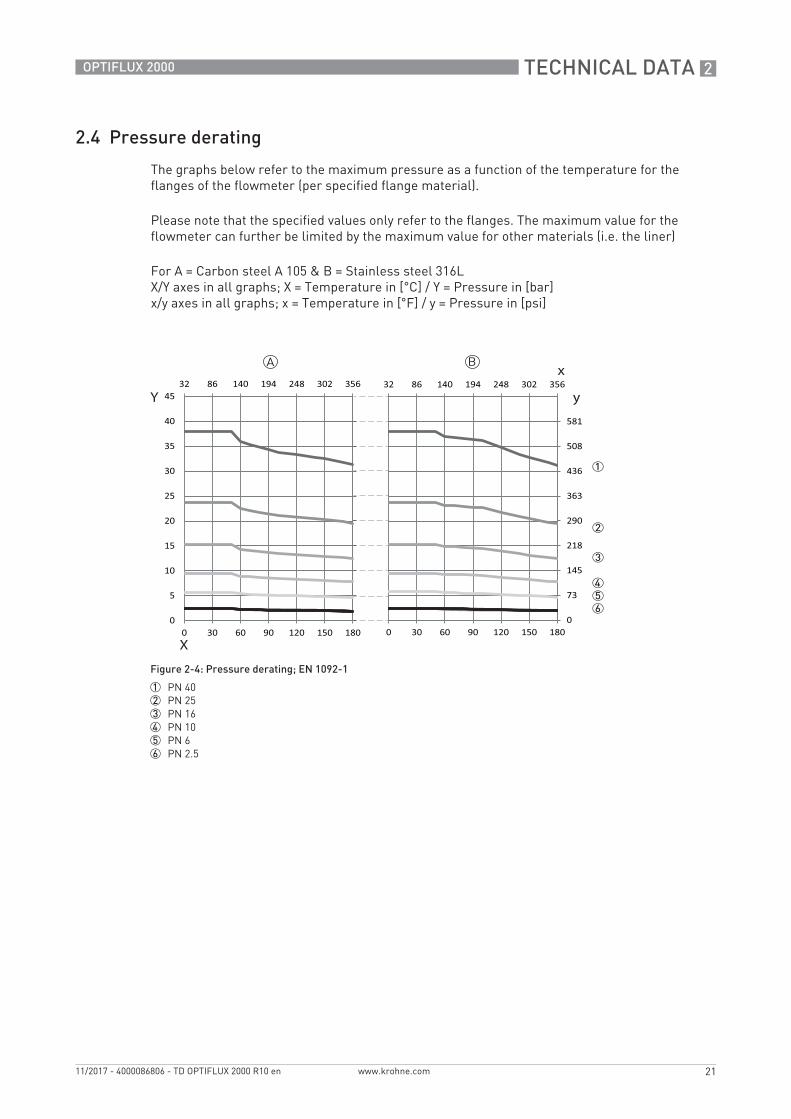
2.4 Pressure derating
The graphs below refer to the maximum pressure as a function of the temperature for the flanges of the flowmeter (per specified flange material).
Please note that the specified values only refer to the flanges. The maximum value for the flowmeter can further be limited by the maximum value for other materials (i.e. the liner)
For A = Carbon steel A 105 & B = Stainless steel 316LX/Y axes in all graphs; X = Temperature in [°C] / Y = Pressure in [bar]x/y axes in all graphs; x = Temperature in [°F] / y = Pressure in [psi]
Figure 2-4: Pressure derating; EN 1092-1
1 PN 402 PN 253 PN 164 PN 105 PN 66 PN 2.5
2 TECHNICAL DATA
22
OPTIFLUX 2000
www.krohne.com 11/2017 - 4000086806 - TD OPTIFLUX 2000 R10 en
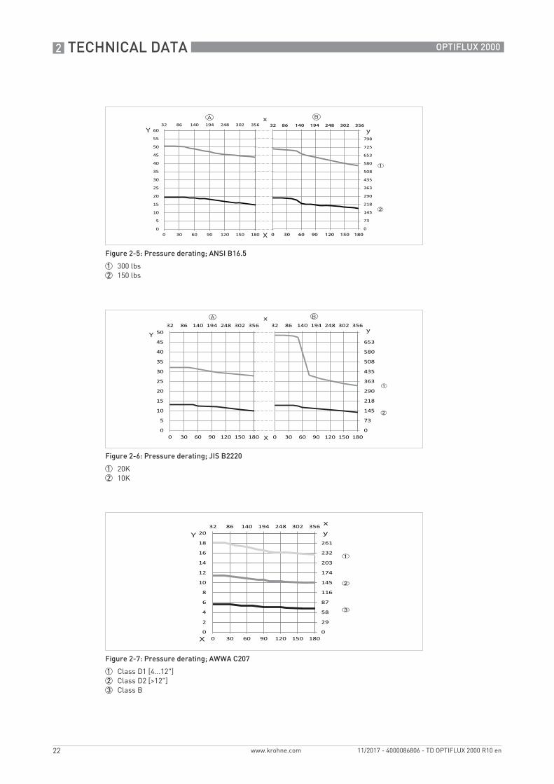
Figure 2-5: Pressure derating; ANSI B16.5
1 300 lbs2 150 lbs
Figure 2-6: Pressure derating; JIS B2220
1 20K2 10K
Figure 2-7: Pressure derating; AWWA C207
1 Class D1 [4...12"]2 Class D2 [>12"]3 Class B
TECHNICAL DATA 2
23
OPTIFLUX 2000
www.krohne.com11/2017 - 4000086806 - TD OPTIFLUX 2000 R10 en
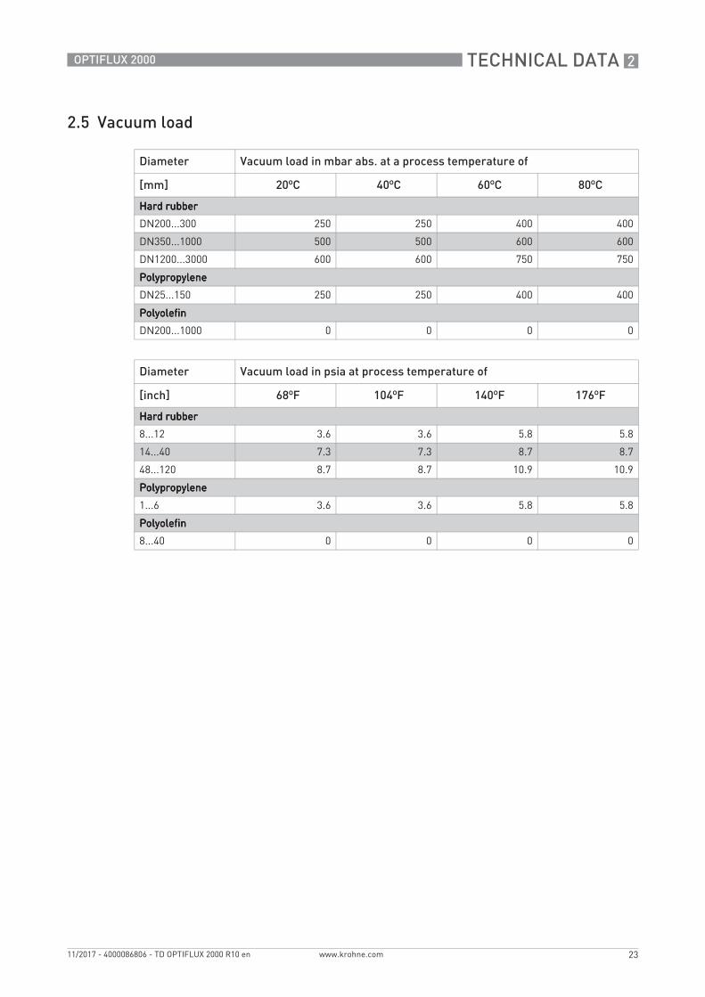
2.5 Vacuum load
Diameter Vacuum load in mbar abs. at a process temperature of
www.krohne.com 11/2017 - 4000086806 - TD OPTIFLUX 2000 R10 en
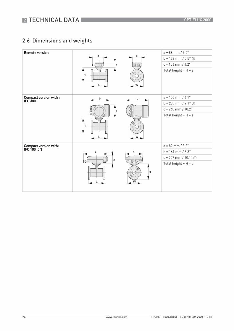
2.6 Dimensions and weights
Remote versionRemote versionRemote versionRemote version a = 88 mm / 3.5"
b = 139 mm / 5.5" 1
c = 106 mm / 4.2"
Total height = H + a
Compact version with :Compact version with :Compact version with :Compact version with :IFC 300IFC 300IFC 300IFC 300
a = 155 mm / 6,1"
b = 230 mm / 9.1" 1
c = 260 mm / 10.2"
Total height = H + a
Compact version with:Compact version with:Compact version with:Compact version with:IFC 100 (0IFC 100 (0IFC 100 (0IFC 100 (0°))))
a = 82 mm / 3.2"
b = 161 mm / 6.3"
c = 257 mm / 10.1" 1
Total height = H + a
TECHNICAL DATA 2
25
OPTIFLUX 2000
www.krohne.com11/2017 - 4000086806 - TD OPTIFLUX 2000 R10 en
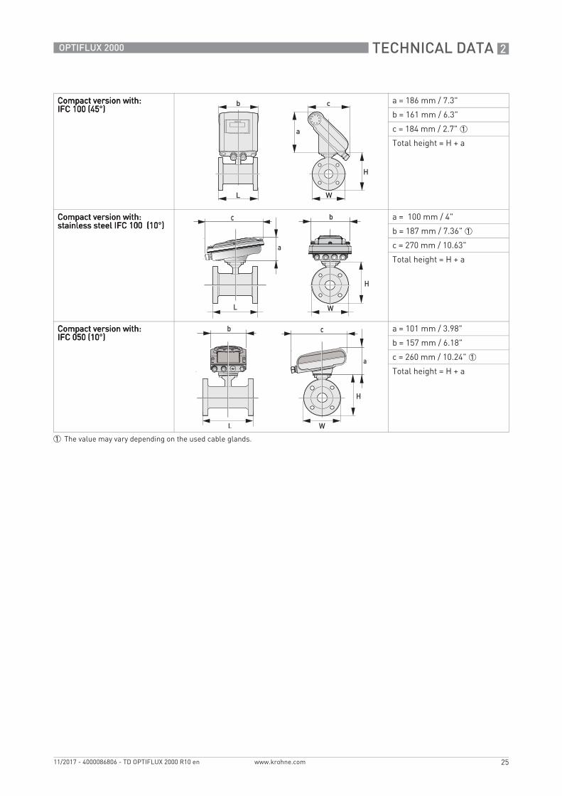
Compact version with:Compact version with:Compact version with:Compact version with:IFC 100 (45IFC 100 (45IFC 100 (45IFC 100 (45°))))
a = 186 mm / 7.3"
b = 161 mm / 6.3"
c = 184 mm / 2.7" 1
Total height = H + a
Compact version with:Compact version with:Compact version with:Compact version with:stainless steel IFC 100 (10stainless steel IFC 100 (10stainless steel IFC 100 (10stainless steel IFC 100 (10°))))
a = 100 mm / 4"
b = 187 mm / 7.36" 1
c = 270 mm / 10.63"
Total height = H + a
Compact version with:Compact version with:Compact version with:Compact version with:IFC 050 (10IFC 050 (10IFC 050 (10IFC 050 (10°))))
a = 101 mm / 3.98"
b = 157 mm / 6.18"
c = 260 mm / 10.24" 1
Total height = H + a
1 The value may vary depending on the used cable glands.
2 TECHNICAL DATA
26
OPTIFLUX 2000
www.krohne.com 11/2017 - 4000086806 - TD OPTIFLUX 2000 R10 en
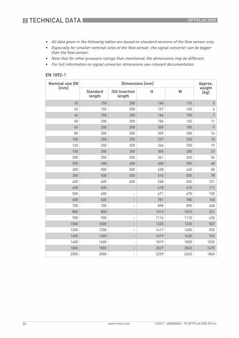
EN 1092-1
• All data given in the following tables are based on standard versions of the flow sensor only.• Especially for smaller nominal sizes of the flow sensor, the signal converter can be bigger
than the flow sensor.• Note that for other pressure ratings than mentioned, the dimensions may be different.• For full information on signal converter dimensions see relevant documentation.
Nominal size DN [mm]
Dimensions [mm] Approx. weight
[kg]Standard length
ISO Insertion length
H W
25 150 200 140 115 5
32 150 200 157 140 6
40 150 200 166 150 7
50 200 200 186 165 11
65 200 200 200 185 9
80 200 200 209 200 14
100 250 250 237 220 15
125 250 250 266 250 19
150 300 300 300 285 27
200 350 350 361 340 34
250 400 450 408 395 48
300 500 500 458 445 58
350 500 550 510 505 78
400 600 600 568 565 101
450 600 - 618 615 111
500 600 - 671 670 130
600 600 - 781 780 165
700 700 - 898 895 248
800 800 - 1012 1015 331
900 900 - 1114 1115 430
1000 1000 - 1225 1230 507
1200 1200 - 1417 1405 555
1400 1400 - 1619 1630 765
1600 1600 - 1819 1830 1035
1800 1800 - 2027 2045 1470
2000 2000 - 2259 2265 1860
TECHNICAL DATA 2
27
OPTIFLUX 2000
www.krohne.com11/2017 - 4000086806 - TD OPTIFLUX 2000 R10 en
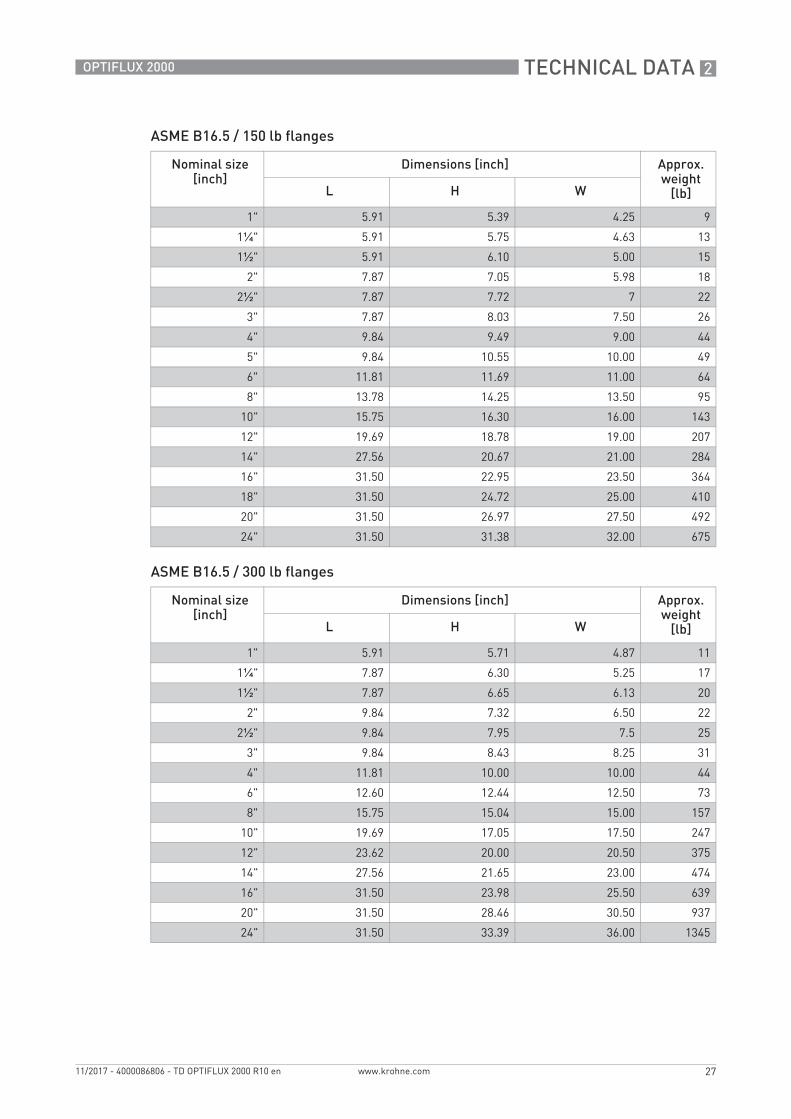
ASME B16.5 / 150 lb flanges
ASME B16.5 / 300 lb flanges
Nominal size [inch]
Dimensions [inch] Approx. weight
[lb]L H W
1" 5.91 5.39 4.25 9
1¼" 5.91 5.75 4.63 13
1½" 5.91 6.10 5.00 15
2" 7.87 7.05 5.98 18
2½" 7.87 7.72 7 22
3" 7.87 8.03 7.50 26
4" 9.84 9.49 9.00 44
5" 9.84 10.55 10.00 49
6" 11.81 11.69 11.00 64
8" 13.78 14.25 13.50 95
10" 15.75 16.30 16.00 143
12" 19.69 18.78 19.00 207
14" 27.56 20.67 21.00 284
16" 31.50 22.95 23.50 364
18" 31.50 24.72 25.00 410
20" 31.50 26.97 27.50 492
24" 31.50 31.38 32.00 675
Nominal size [inch]
Dimensions [inch] Approx. weight
[lb]L H W
1" 5.91 5.71 4.87 11
1¼" 7.87 6.30 5.25 17
1½" 7.87 6.65 6.13 20
2" 9.84 7.32 6.50 22
2½" 9.84 7.95 7.5 25
3" 9.84 8.43 8.25 31
4" 11.81 10.00 10.00 44
6" 12.60 12.44 12.50 73
8" 15.75 15.04 15.00 157
10" 19.69 17.05 17.50 247
12" 23.62 20.00 20.50 375
14" 27.56 21.65 23.00 474
16" 31.50 23.98 25.50 639
20" 31.50 28.46 30.50 937
24" 31.50 33.39 36.00 1345
3 INSTALLATION
28
OPTIFLUX 2000
www.krohne.com 11/2017 - 4000086806 - TD OPTIFLUX 2000 R10 en
3.1 Intended use
The OPTIFLUX 2000 electromagnetic flowmeter is designed exclusively to measure the flow of electrically conductive, liquid media.
3.2 General notes on installation
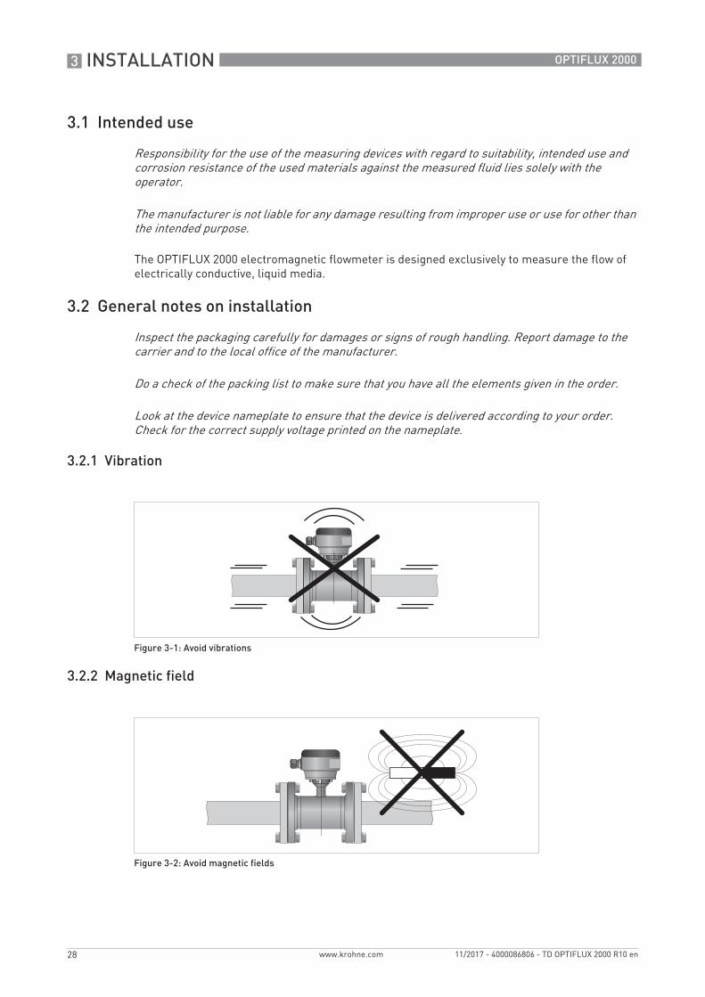
3.2.1 Vibration
3.2.2 Magnetic field
Responsibility for the use of the measuring devices with regard to suitability, intended use and corrosion resistance of the used materials against the measured fluid lies solely with the operator.
The manufacturer is not liable for any damage resulting from improper use or use for other than the intended purpose.
Inspect the packaging carefully for damages or signs of rough handling. Report damage to the carrier and to the local office of the manufacturer.
Do a check of the packing list to make sure that you have all the elements given in the order.
Look at the device nameplate to ensure that the device is delivered according to your order. Check for the correct supply voltage printed on the nameplate.
Figure 3-1: Avoid vibrations
Figure 3-2: Avoid magnetic fields
INSTALLATION 3
29
OPTIFLUX 2000
www.krohne.com11/2017 - 4000086806 - TD OPTIFLUX 2000 R10 en
3.3 Installation conditions
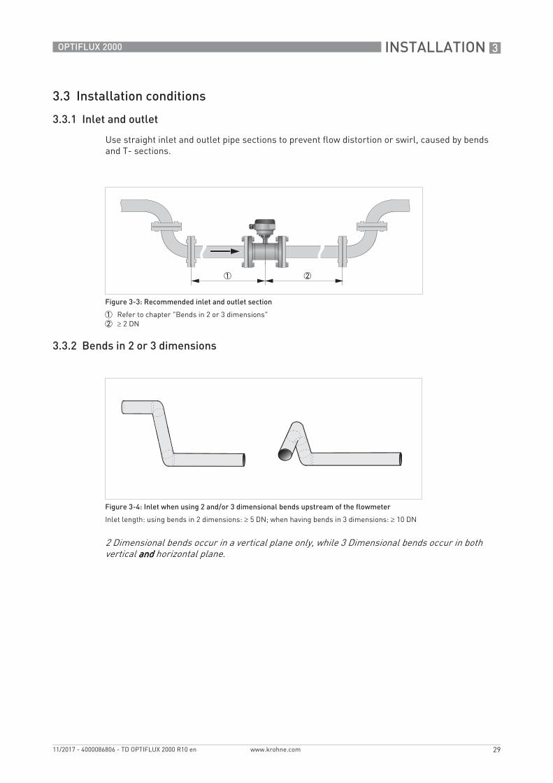
3.3.1 Inlet and outlet
Use straight inlet and outlet pipe sections to prevent flow distortion or swirl, caused by bends and T- sections.
3.3.2 Bends in 2 or 3 dimensions
Figure 3-3: Recommended inlet and outlet section
1 Refer to chapter "Bends in 2 or 3 dimensions"2 2 DN
Figure 3-4: Inlet when using 2 and/or 3 dimensional bends upstream of the flowmeter
Inlet length: using bends in 2 dimensions: 5 DN; when having bends in 3 dimensions: 10 DN
2 Dimensional bends occur in a vertical plane only, while 3 Dimensional bends occur in both vertical andandandand horizontal plane.
3 INSTALLATION
30
OPTIFLUX 2000
www.krohne.com 11/2017 - 4000086806 - TD OPTIFLUX 2000 R10 en
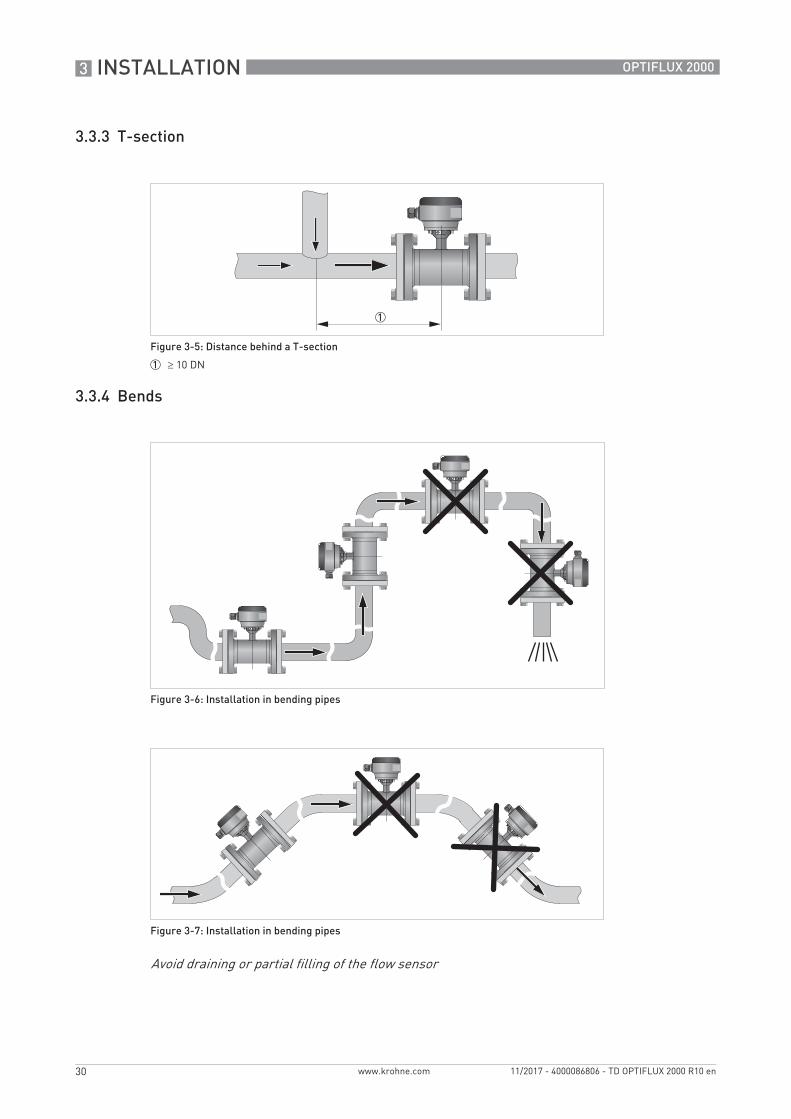
3.3.3 T-section
3.3.4 Bends
Figure 3-5: Distance behind a T-section
1 10 DN
Figure 3-6: Installation in bending pipes
Figure 3-7: Installation in bending pipes
Avoid draining or partial filling of the flow sensor
INSTALLATION 3
31
OPTIFLUX 2000
www.krohne.com11/2017 - 4000086806 - TD OPTIFLUX 2000 R10 en
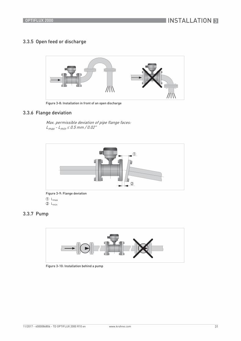
3.3.5 Open feed or discharge
3.3.6 Flange deviation
3.3.7 Pump
Figure 3-8: Installation in front of an open discharge
Max. permissible deviation of pipe flange faces:Lmax - Lmin 0.5 mm / 0.02"
Figure 3-9: Flange deviation
1 Lmax2 Lmin
Figure 3-10: Installation behind a pump
3 INSTALLATION
32
OPTIFLUX 2000
www.krohne.com 11/2017 - 4000086806 - TD OPTIFLUX 2000 R10 en
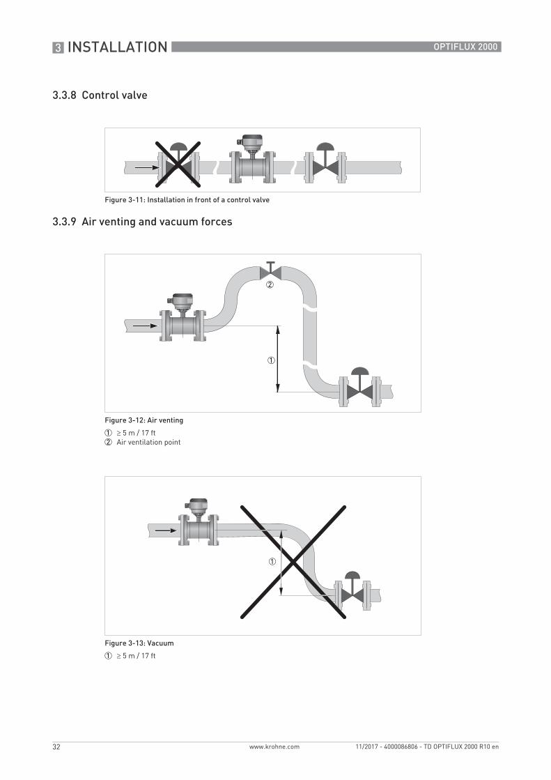
3.3.8 Control valve
3.3.9 Air venting and vacuum forces
Figure 3-11: Installation in front of a control valve
Figure 3-12: Air venting
1 5 m / 17 ft2 Air ventilation point
Figure 3-13: Vacuum
1 5 m / 17 ft
INSTALLATION 3
33
OPTIFLUX 2000
www.krohne.com11/2017 - 4000086806 - TD OPTIFLUX 2000 R10 en
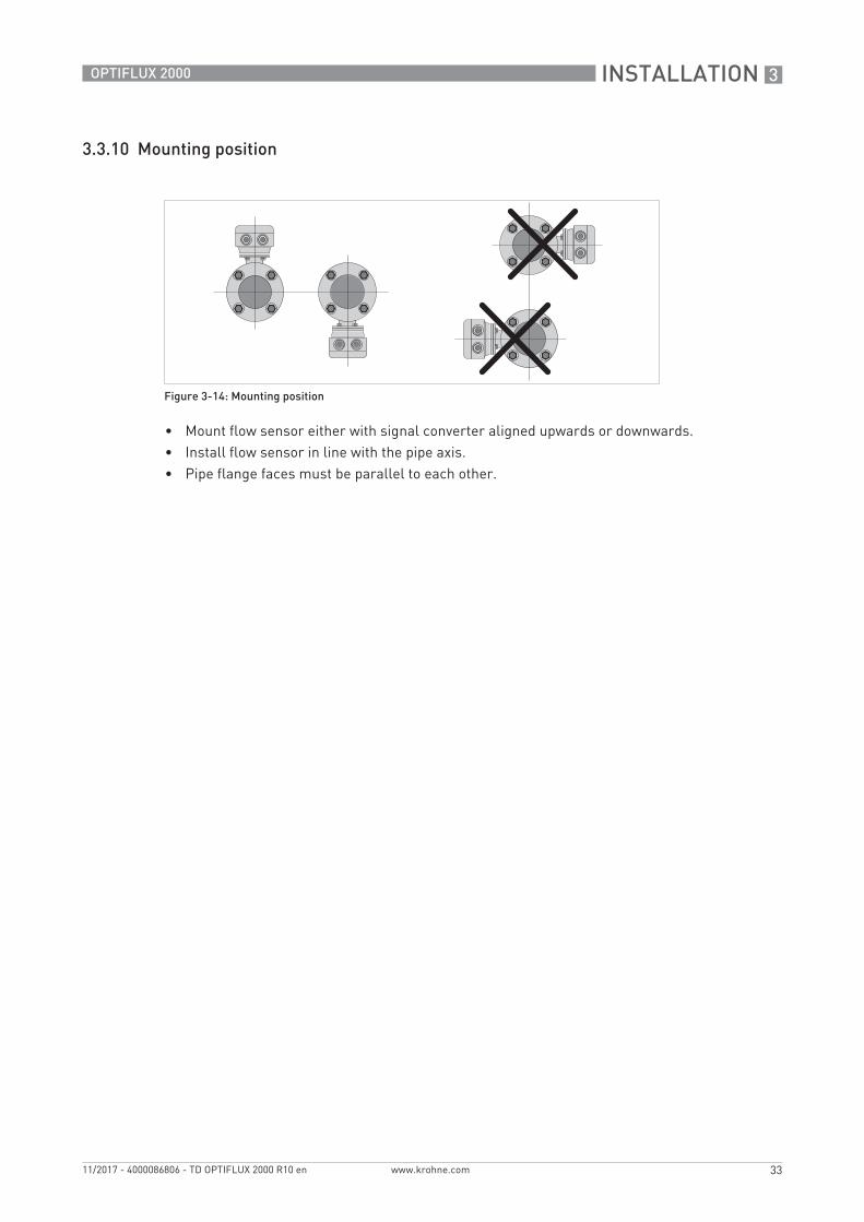
3.3.10 Mounting position
• Mount flow sensor either with signal converter aligned upwards or downwards.• Install flow sensor in line with the pipe axis.• Pipe flange faces must be parallel to each other.
Figure 3-14: Mounting position
3 INSTALLATION
34
OPTIFLUX 2000
www.krohne.com 11/2017 - 4000086806 - TD OPTIFLUX 2000 R10 en
3.4 Mounting
3.4.1 Torques and pressures
The maximum pressure and torques values for the flowmeter are theoretical and calculated for optimum conditions and use with carbon steel flanges.
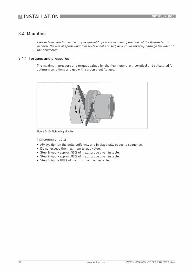
Tightening of bolts• Always tighten the bolts uniformly and in diagonally opposite sequence.• Do not exceed the maximum torque value.• Step 1: Apply approx. 50% of max. torque given in table.• Step 2: Apply approx. 80% of max. torque given in table.• Step 3: Apply 100% of max. torque given in table.
Please take care to use the proper gasket to prevent damaging the liner of the flowmeter. In general, the use of spiral wound gaskets is not advised, as it could severely damage the liner of the flowmeter.
Figure 3-15: Tightening of bolts
INSTALLATION 3
35
OPTIFLUX 2000
www.krohne.com11/2017 - 4000086806 - TD OPTIFLUX 2000 R10 en
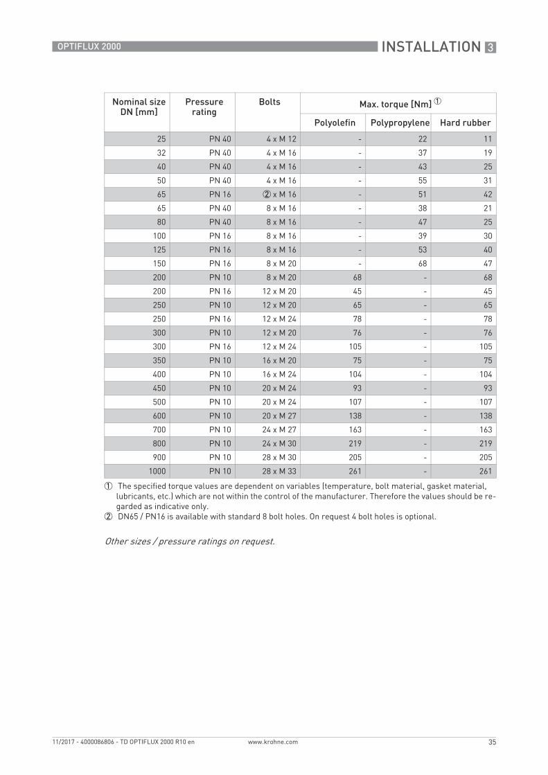
Nominal sizeDN [mm]
Pressurerating
Bolts Max. torque [Nm] 1
Polyolefin Polypropylene Hard rubber
25 PN 40 4 x M 12 - 22 11
32 PN 40 4 x M 16 - 37 19
40 PN 40 4 x M 16 - 43 25
50 PN 40 4 x M 16 - 55 31
65 PN 16 2 x M 16 - 51 42
65 PN 40 8 x M 16 - 38 21
80 PN 40 8 x M 16 - 47 25
100 PN 16 8 x M 16 - 39 30
125 PN 16 8 x M 16 - 53 40
150 PN 16 8 x M 20 - 68 47
200 PN 10 8 x M 20 68 - 68
200 PN 16 12 x M 20 45 - 45
250 PN 10 12 x M 20 65 - 65
250 PN 16 12 x M 24 78 - 78
300 PN 10 12 x M 20 76 - 76
300 PN 16 12 x M 24 105 - 105
350 PN 10 16 x M 20 75 - 75
400 PN 10 16 x M 24 104 - 104
450 PN 10 20 x M 24 93 - 93
500 PN 10 20 x M 24 107 - 107
600 PN 10 20 x M 27 138 - 138
700 PN 10 24 x M 27 163 - 163
800 PN 10 24 x M 30 219 - 219
900 PN 10 28 x M 30 205 - 205
1000 PN 10 28 x M 33 261 - 261
1 The specified torque values are dependent on variables (temperature, bolt material, gasket material,lubricants, etc.) which are not within the control of the manufacturer. Therefore the values should be re-garded as indicative only.
2 DN65 / PN16 is available with standard 8 bolt holes. On request 4 bolt holes is optional.
Other sizes / pressure ratings on request.
3 INSTALLATION
36
OPTIFLUX 2000
www.krohne.com 11/2017 - 4000086806 - TD OPTIFLUX 2000 R10 en
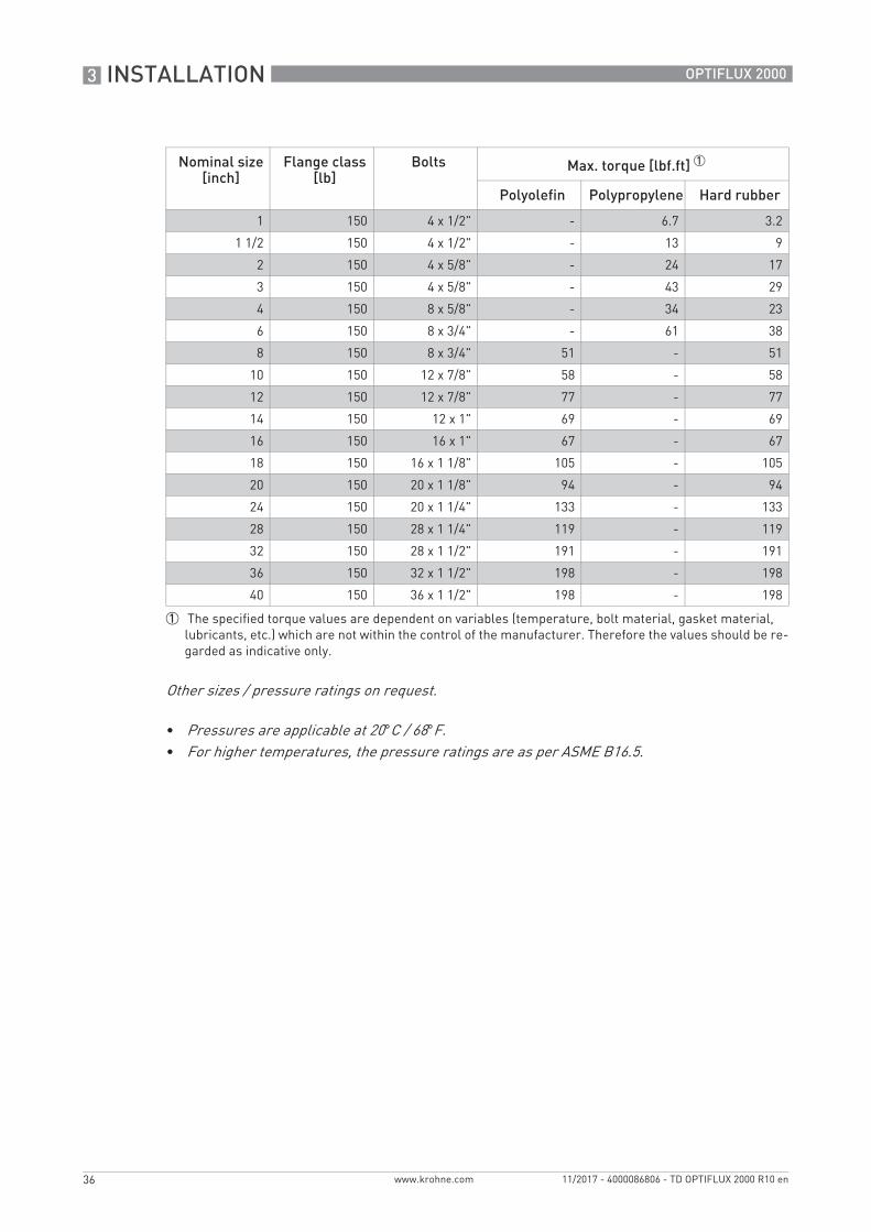
Nominal size[inch]
Flange class[lb]
Bolts Max. torque [lbf.ft] 1
Polyolefin Polypropylene Hard rubber
1 150 4 x 1/2" - 6.7 3.2
1 1/2 150 4 x 1/2" - 13 9
2 150 4 x 5/8" - 24 17
3 150 4 x 5/8" - 43 29
4 150 8 x 5/8" - 34 23
6 150 8 x 3/4" - 61 38
8 150 8 x 3/4" 51 - 51
10 150 12 x 7/8" 58 - 58
12 150 12 x 7/8" 77 - 77
14 150 12 x 1" 69 - 69
16 150 16 x 1" 67 - 67
18 150 16 x 1 1/8" 105 - 105
20 150 20 x 1 1/8" 94 - 94
24 150 20 x 1 1/4" 133 - 133
28 150 28 x 1 1/4" 119 - 119
32 150 28 x 1 1/2" 191 - 191
36 150 32 x 1 1/2" 198 - 198
40 150 36 x 1 1/2" 198 - 198
1 The specified torque values are dependent on variables (temperature, bolt material, gasket material,lubricants, etc.) which are not within the control of the manufacturer. Therefore the values should be re-garded as indicative only.
Other sizes / pressure ratings on request.
• Pressures are applicable at 20°C / 68°F.• For higher temperatures, the pressure ratings are as per ASME B16.5.
ELECTRICAL CONNECTIONS 4
37
OPTIFLUX 2000
www.krohne.com11/2017 - 4000086806 - TD OPTIFLUX 2000 R10 en
4.1 Safety instructions
4.2 Grounding
All work on the electrical connections may only be carried out with the power disconnected. Take note of the voltage data on the nameplate!
Observe the national regulations for electrical installations!
Observe without fail the local occupational health and safety regulations. Any work done on the electrical components of the measuring device may only be carried out by properly trained specialists.
Look at the device nameplate to ensure that the device is delivered according to your order. Check for the correct supply voltage printed on the nameplate.
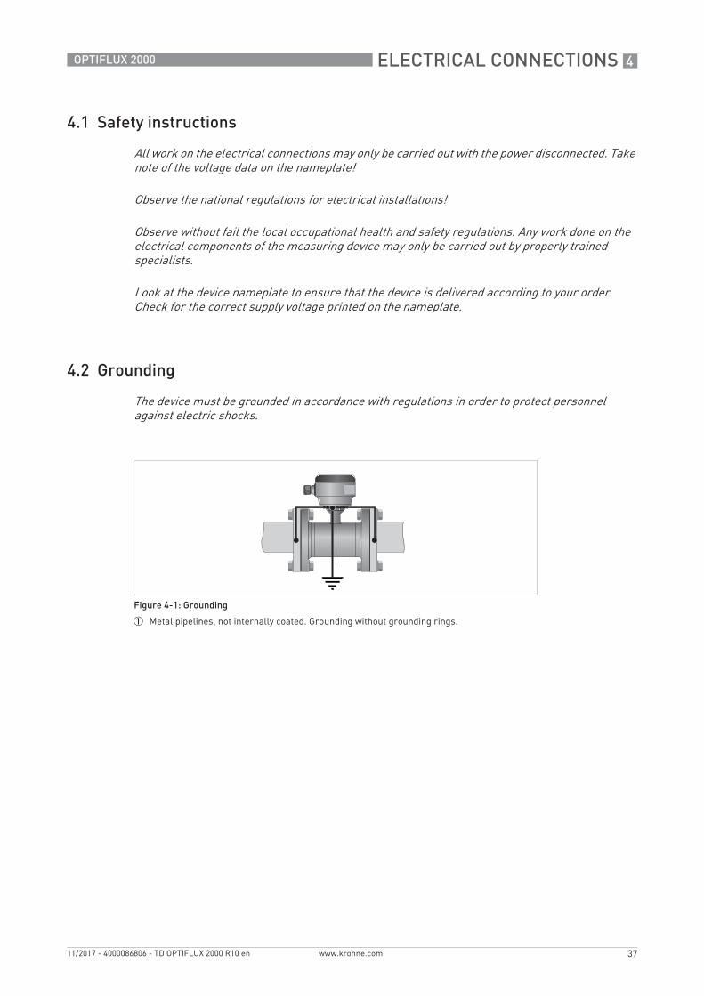
The device must be grounded in accordance with regulations in order to protect personnel against electric shocks.
Figure 4-1: Grounding
1 Metal pipelines, not internally coated. Grounding without grounding rings.
4 ELECTRICAL CONNECTIONS
38
OPTIFLUX 2000
www.krohne.com 11/2017 - 4000086806 - TD OPTIFLUX 2000 R10 en
Grounding ring number 1:• Thickness : 3 mm / 0.1" (tantalum: 0.5 mm / 0.02")
Grounding ring number 2:• Thickness : 3 mm / 0.1"• Prevents damage to the flanges during transport and installation• Especially for flow sensors with PTFE liner
Grounding ring number 3:• Thickness : 3 mm / 0.1"• With cylindrical neck (length 30 mm / 1.25" for DN10...150 / 3/8...6")• Offers liner protection against abrasive fluids
Figure 4-2: Different types of grounding rings
1 Grounding ring number 12 Grounding ring number 23 Grounding ring number 3
ELECTRICAL CONNECTIONS 4
39
OPTIFLUX 2000
www.krohne.com11/2017 - 4000086806 - TD OPTIFLUX 2000 R10 en
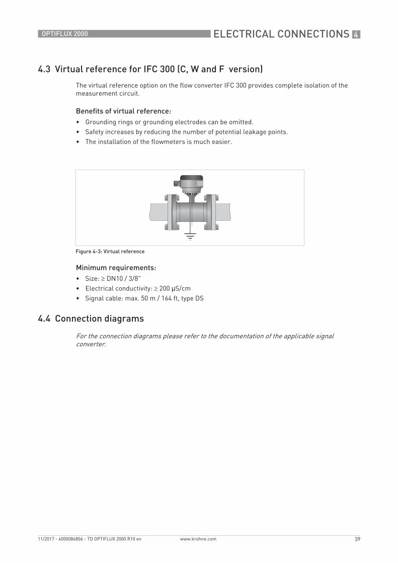
4.3 Virtual reference for IFC 300 (C, W and F version)
The virtual reference option on the flow converter IFC 300 provides complete isolation of the measurement circuit.
Benefits of virtual reference:• Grounding rings or grounding electrodes can be omitted.• Safety increases by reducing the number of potential leakage points.• The installation of the flowmeters is much easier.
Minimum requirements:• Size: DN10 / 3/8"• Electrical conductivity: 200 μS/cm• Signal cable: max. 50 m / 164 ft, type DS
4.4 Connection diagrams
Figure 4-3: Virtual reference
For the connection diagrams please refer to the documentation of the applicable signal converter.
KROHNE – Process instrumentation and measurement solutions


![OIML R 49-1 (E) 2006 - ZEN SERVIS International recommendation OIML R...OIML D 11 ]. OIML R 49-1: 2006 (E) 7 2.2.10 Significant fault Fault, the magnitude of which is greater than](https://static.documents.pub/doc/80x56/5add5cf97f8b9a9d4d8d12e1/oiml-r-49-1-e-2006-zen-international-recommendation-oiml-roiml-d-11-oiml.jpg)


