P/No.: 3828EL3004P TD-V10247G TD-V14247E TD-V14247G Thank you for buying an LG Dryer. Please read your manual carefully, as it provides instructions on safe Installation, use and maintenance. Record the model and serial numbers, and retain the manual for future reference.
Transcript
P/No.: 3828EL3004P
TD-V10247GTD-V14247ETD-V14247G
Thank you for buying an LG Dryer. Please read your manual carefully, as it provides instructionson safe Installation, use and maintenance. Record the model and serial numbers,and retain the manual for future reference.
PRODUCT FEATURES
TABLE OF CONTENTS
22
PART 1. SPECIFICATIONS ................................................................................................................................................................................................................ 3
PART 2. IMPORTANT WARRANTY AND SAFETY INSTRUCTIONS .............................................................................................................................................. 4
PART 3. INITIAL STEPS FOR INSTALLING YOUR DRYER ........................................................................................................................................................... 11
PART 4. ACCESSORIES INSTALLATION ....................................................................................................................................................................................... 16
PART 5. ELECTRICAL REQUIREMENTS FOR ELECTRIC DRYERS ............................................................................................................................................. 18
PART 6. ELECTRICAL REQUIREMENTS FOR GAS DRYERS........................................................................................................................................................ 22
PART 7. GAS REQUIREMENTS AND INSTRUCTIONS ................................................................................................................................................................... 23
PART 8. EXHAUST REQUIREMENTS AND MAINTENANCE .......................................................................................................................................................... 24
PART 9. OPERATING YOUR DRYER ............................................................................................................................................................................................... 26
PART 10. TROUBLESHOOTING GUIDE........................................................................................................................................................................................... 32
What are Sensor Dry and Time Dry?
Your dryer provides sensor drying and time drying programs.
Sensor DryThe dryer senses the dampness of the laundry and automatically determines the heat level and operation time. You mightsee a sudden increase or decrease in operation time if the sensor determines more or less drying is required. This is not amalfunction.
Time Dry
Use TIME DRY to select heat level and drying time manually. This can be used if clothes are not as dry as you like themat the end of the cycle. Use TIME DRY for heavy and bulky items and thick work.
OUTSTANDING PERFORMANCENot to mention unmatched big capacity, you can benefit from goodtime efficiency, quiet operation and energy saving system.
ARTISTIC DESIGNModern front panel look and big crystal-clear glass door make your house look stylish.
DIGITAL FABRIC CAREMulti-level temperature control heater takes a better care on your valued clothes.
EASY OF USEA whole selection of user-friendly functions always make you comfortable with dryer operation.
1
2
3
4
3
Part 1 SPECIFICATIONS
■ Type : Electric and Gas Dryer
■ Rating : Please refer to the rating label regarding detailed information.
■ Size : 686 x 761 x 983(mm)
■ Capacity : Please refer to the rating label regarding detailed information.
■ Weight : 57.2 kg
Specifications are subject to change by manufacturer.
See page 16 for instructions. See page 17 for instructions.
Stacking Kit
Purchased Separately
Pedestal Purchased Separately
Design of pedestals is subject tochange without manafaturers notice.
■ ACCESSORIES
The warranty for your dryer is located at the end of this manual. Warranty Service isavailable by contacting your nearest LG Service Center. If this product is installed andoperated according to the instructions in this manual, LG will repair or replace any partsdefective in material or workmanship throughout the warranty period, beginning with thedate of purchase.
Warranty Restriction: If the dryer is subjected to other than single family use, all warrantycoverage is effective for only 90 days.
You will need the complete model and serial number when requesting warranty service. proof ofpurchase date is required.
Use the space below to record the model number and serial number of your new LG dryer.
Model Number.
Serial Number.
Date of Purchase
❈ Staple your receipt here for convenience when contacting service.
Part 2
4
IMPORTANT WARRANTY AND SAFETY INSTRUCTIONS
SEEKING WARRANTY SERVICE
WARNING!For your safety, the recommendations in this manual must be followed. To reduce the riskof fire or explosion, electric shock or to prevent property damage, personal injury, or deathwhen using your appliance follow basic precautions.
5
Part 2 IMPORTANT WARRANTY AND SAFETY INSTRUCTIONS
• Read all instructions before using the dryer.• Before use, the dryer must be properly installed
as described in this manual.• Do not place items exposed to cooking oils in
your dryer. Items contaminated with cooking oilsmay contribute to a chemical reaction that couldcause a load to catch fire. Do not dry articles that have been previouslycleaned in, washed in, soaked in, or spotted withgasoline, dry-cleaning solvents, other flammableor explosive substances as they give off vaporsthat could ignite or explode.
• Do not reach into the dryer if the drum is moving.• Do not repair or replace any part of the dryer or
attempt any servicing unless specificallyrecommended in this Use and Care Guide or inpublished user-repair instructions that youunderstand and have the skills to carry out.
• Do not tamper with controls.• Before the dryer is removed from service or discarded,
remove the door to the drying compartment.
• Do not allow children to play on or in the dryer. Close supervision of children is necessary whenthe dryer is used near children.
• Do not use fabric softeners or products toeliminate static unless recommended by themanufacturer of the fabric softener or product.
• Do not use heat to dry articles containing foamrubber or similarly textured rubber-like materials.
• Keep area around the exhaust opening andadjacent surrounding areas free from theaccumulation of lint, dust, and dirt.
• The interior of the dryer and exhaust vent shouldbe cleaned periodically by qualified servicepersonnel.
• Do not install or store the dryer where it will beexposed to the weather.
• Do not reach into the dryer while parts aremoving.
• Always check the inside of the dryer for foreign objects• Clean lint screen before or after each load.
Your Safety and the safety of others are very important.
BASIC SAFETY PRECAUTIONS
SAVE THESE INSTRUCTIONS
DANGER You can be killed or seriously injured if you don’t Immediately follow instructions.
You can be killed or seriously injured if you don’t follow instructions.
To reduce the risk of fire, electric shock or injury to persons when using yourappliance, follow basic precautions, including the following :
WARNING
WARNING
We have provided many important safety messages in this manual and on your appliance.Always read and obey all safety messages.
All safety messages will tell you what the potential hazard is, tell you how the reduce thechance of injury, and tell you what can happen if the instructions are not followed.
This is the safety alert symbol.This symbol alerts you to potential hazards that can kill or hurt you and others.All safety messages will follow the safety alert symbol and either the word DANGER or WARNING.These words mean:
READ ALL INSTRUCTIONS BEFORE USEFor your safety, the information in this manual must be followed to minimize the risk of fireor explosion, electric shock, or to prevent property damage, personal injury, or loss of life.
WARNING
Part 2 IMPORTANT WARRANTY AND SAFETY INSTRUCTIONS
6
• Do not store or use gasoline or otherflammable vapors and liquids in the vicinityof this appliance or any other appliance.
• Installation and service must be performedby a qualified installer, service agency, orthe gas supplier.
READ ALL INSTRUCTIONS BEFORE USE
For your safety, the information in this manual must be followed to minimize the risk offire or explosion, electric shock, or to prevent property damage, personal injury, or lossof life.
WARNING
BASIC SAFETY PRECAUTIONS
To reduce the risk of fire, electric shock or injury to persons when using yourappliance, follow basic precautions, including the following :
WARNING
GROUNDING INSTRUCTIONSThis appliance must be grounded. In the event of malfunction or breakdown,grounding will reduce the risk of electric shockby providing a path of least resistance forelectric current. This appliance must beequipped with a cord having an equipment-grounding conductor and a grounding plug.The plug must be plugged into an appropriateoutlet that is properly installed and groundedin accordance with all local codes andordinances.
WARNING - Improper connection of theequipment- rounding conductor can result in arisk of electric shock. Check with a qualifiedelectrician or service person if you are in doubtas to whether the appliance is properlygrounded.Do not modify the plug provided with theappliance.
If it will not fit the outlet, have a proper outletinstalled by a qualified electrician.
This appliance must be connected to agrounded metal, permanent wiring system or anequipment-grounding conductor must be runwith the circuit conductors and connected to theequipment-grounding terminal or lead on theappliance.
7
Part 2 IMPORTANT WARRANTY AND SAFETY INSTRUCTIONS
1. Do not try to light a match or cigarette, orturn on any gas or electrical appliance.
2. Do not touch any electrical switches.Do not use any phone in your building.
3. Clear the room, building, or area of alloccupants.
4. Immediately call your gas supplier from aneighbor’s phone. Follow the gas supplier’sphone. Follow the gas supplier’sinstructions carefully.
5. If you cannot reach your gas supplier, callthe fire department.
WHAT TO DO IF YOU SMELL GAS
To reduce the risk of fire, electric shock, or injury to persons when using theappliance, follow basic precautions, including the following:
WARNING
READ ALL INSTRUCTIONS BEFORE USE
For your safety, the information in this manual must be followed to minimize the risk offire or explosion, electric shock, or to prevent property damage, personal injury, or lossof life.
WARNING
Part 2 IMPORTANT WARRANTY AND SAFETY INSTRUCTIONS
8
• Properly ground dryer to conform withall governing codes and ordinances.Follow details in the installationinstructions.
Electrical shock can result if the dryer is notproperly grounded.
• Before use, the dryer must be properlyinstalled as described in this manual.
Electrical shock can result if the dryer is notproperly grounded.
• Install and store the dryer where it willnot be exposed to temperatures belowfreezing or exposed to the weather.
All repairs and servicing must be performedby an authorized servicer unless specificallyrecommended in this Owner's Guide. Use only authorized factory parts. Failure to follow this warning can causeserious injury,fire, electrical shock or death.
• Do not install the washer in humidspaces to reduce the risk of electricshock.
Failure to follow this warning can causeserious injury,fire, electrical shock or death.
• Connect to a properly rated, protected,and sized power circuit to avoidelectrical overload.
Improper power circuit can melt, creatingelectrical shock and/or fire hazard.
• Remove all packing items and disposeof all shipping materials properly.
Failure to do so can result in death,explosion, fire or burns.
• Place dryer at least 18 in. above the floorfor a garage installation.
Failure to do so can result in death,explosion, fire or burns.
READ ALL INSTRUCTIONS BEFORE USE
SAFETY INSTRUCTION FOR INSTALLATION
To reduce the risk of fire, electric shock, or injury to persons when using theappliance, follow basic precautions, including the following:
WARNING
For your safety, the information in this manual must be followed to minimize the risk offire or explosion, electric shock, or to prevent property damage, personal injury, or lossof life.
WARNING
9
Part 2 IMPORTANT WARRANTY AND SAFETY INSTRUCTIONS
Exhaust/Ducting:
• Gas dryers MUST be exhausted to theoutside.
Failure to follow these instructions can resultin fire or death.
• The dryer exhaust system must beexhausted to the outside of the dwelling.
The dryer is not exhausted outdoors, somefine lint and large amounts of moisture willbe expelled into the laundry area. Anaccumulation of lint in any area of the homecan create a health and fire hazard.
• Use only rigid metal or flexible metal 4in.Diameter ductwork inside the dryercabinet or for exhausting to the outside.
Use of plastic or other combustible ductworkcan cause a fire. Punctured ductwork cancause a fire if it collapses or becomesotherwise restricted in use or duringinstallation.
• Ductwork is not provided with the dryer,and you should obtain the necessaryductwork locally. The end cap shouldhave hinged dampers to prevent backdraft when the dryer is not in use.
Failure to follow these instructions can resultin fire or death.
• The exhaust duct must be 4 in. (10 cm)in diameter with no obstructions. Theexhaust duct should be kept as short aspossible. Make sure to clean any oldducts before installing your new dryer.
Failure to follow these instructions can resultin fire or death.
• Rigid or semi rigid metal ducting isrecommended for use between the dryerand the wall. In special installations whenit is impossible to make a connectionwith the above recommendations, a UL-listed flexible metal transition duct maybe used between the dryer and wallconnection only. The use of this ductingwill affect drying time.
Failure to follow these instructions can resultin fire or death.
• DO NOT use sheet metal screws or otherfasteners which extend into the duct thatcould catch lint and reduce the efficiencyof the exhaust system. Secure all jointswith duct tape. ¶U For complete details,follow the Installation Instructions.
Failure to follow these instructions can resultin fire or death.
READ ALL INSTRUCTIONS BEFORE USE
SAFETY INSTRUCTION FOR INSTALLATION (cont.)
For your safety, the information in this manual must be followed to minimize the risk offire or explosion, electric shock, or to prevent property damage, personal injury, or lossof life.
WARNING
Part 2
1 0
IMPORTANT WARRANTY AND SAFETY INSTRUCTIONS
• Do not, under any circumstances, cut orremove the ground prong from the powercord.
To prevent personal injury or damage to thedryer, the electrical power cord must beplugged into a properly grounded
• For personal safety, this dryer must beproperly grounded.
Failure to do so can result in electrical shockor injury
• Refer to the installation instructions inthis manual for specific electricalrequirements for your model.
Failure to follow these instructions cancreate electrical shock and/or a fire hazard.
• This dryer must be plugged into aproperly grounded outlet.
Electrical shock can result if the dryer is notproperly grounded.
• Have the wall outlet and circuit checkedby a qualified electrician to make surethe outlet is properly grounded.
This will prevent shock hazard and assurestability during operating.
• The dryer should always be plugged intoits own individual electrical outlet whichhas a voltage rating that matches therating plate.
This provides the best performance and alsoprevents overloading house wiring circuitswhich could cause a fire hazard fromoverheated wires.
• Never unplug your dryer by pulling onthe power cord. Always grip plug firmlyand pull straight out from the outlet.
The power cord can be cut by anymovement of the core, resulting in electricalshock.
• Repair or replace immediately all powercords that have become frayed orotherwise damaged. Do not use a cordthat shows cracks or abrasion damagealong its length or at either end.
These power cord can melt, creatingelectrical shock and/or fire hazard.
• When installing or moving the dryer, becareful not to pinch, crush, or damagethe power cord.
This will prevent injury and damage to thedryer from fire and electrical shock.
READ ALL INSTRUCTIONS BEFORE USE
SAFETY INSTRUCTION FOR CONNECTING ELECTRICITY
To reduce the risk of fire, electric shock or injury to persons when using the appliance,follow basic precautions, including the following :
WARNING
For your safety, the information in this manual must be followed to minimize the risk offire or explosion, electric shock, or to prevent property damage, personal injury, or lossof life.
WARNING
1 1
Part 3 INITIAL STEPS FOR INSTALLING YOUR DRYER
The following instructions will help guide you through the initial steps of setting up your dryer for use.Please note that every section of this manual provides important information regarding the preparation anduse of your dryer, and it is important that you review this entire manual before proceeding with anyinstallation or use. More detailed instructions concerning electrical connections, gas connections, andexhaust requirements are provided in other parts of this manual.
Choose a location with a solid floor for your dryer.Place the dryer at least eighteen inches above thefloor for a garage installation. After placing thedryer in the desired location, please make sure thatit has the required clearances shown below. If youare installing your dryer in a manufactured ormobile home, please refer to STEP 9 for additionalinstructions.
Certain minimum clearances are requiredabove, behind, and to the sides of the unit, asshown below. Those required minimum clearancesare set forth in the picture below. Please keep thefollowing instructions in mind when installing in acloset or recessed area: • Consider allowing additional clearance for
installation and servicing.• Wall, door and floor molding may necessitate
additional clearances.• An additional inch of clearance is recommended to
minimize noise transfer.• Consider space needed for companion appliances.• For closet installations, the picture below shows the
minimum required ventilation openings for the door. A louvered door with comparable ventilation openingsis also acceptable.
* Most installations require a minimum 51/2 inches. (14 cm) clearance behind the dryer for the exhaustvent with elbow.
Closet-side ViewCloset Door
ventilationhole
ventilationhole
Closet-front View
STEP 1 Positioning the Dryer.
Leveling legs should be secured. All four legs are stably placed on a solid andeven floor.If dryer is not level, laundry may not tumbleproperly and sensor will not detect accuratehumidity information.When leveling, please be cautious not to injureyour fingers and toes. If you install the dryer on the optional pedstal, it is nessary to level with the pedestal levelinglegs.
Note
38.7”(98.3 cm)
27”(68.6 cm)
29.96”(76.1 cm)
49.8”(126.4 cm)
1 2
Part 3 INITIAL STEPS FOR INSTALLING YOUR DRYER
Once in position, adjust the leveling legs of the dryeruntil it is level from left to right and front to back.The leveling legs must remain firmly on the floorand the dryer should not rock. The maximum slopeof the dryer from left to right or front to back shouldnot exceed 2.5 cm (1 inch). If the dryer is not level,and if the slope exceeds 2.5 cm (1 inch), a load maynot tumble properly and internal sensors maymalfunction. Note: Other sections of this manualalso provide important information concerning theplacement of and clearances for your dryer. Pleasereview this entire manual before proceeding with anyinstallation.
The door on your dryer can be installed to openeither to the left or the right. Follow theseinstructions to reverse the direction in which yourdoor opens:
STEP 2: STEP 2 Procedure forReversing the Door
Door and latch should be aligned at the centerwhen closed.
Note
1
2
3
1 3
Part 3 INITIAL STEPS FOR INSTALLING YOUR DRYER
In addition to the following warnings, please referto manual section on Exhaust Requirements andMaintenance. Warning: The dryer must be ventedto the outdoors. Please follow the instructions (andall others in this manual) very carefully. Failure tofollow these instructions can result in death or fire.
• Do not use plastic or thin foil duct.• Rigid or semi-rigid metal ducting is recommended
for use as transition ducting between the dryer andand the wall. In special installations when it isimpossible to make a connection with the aboverecommendations, then a UL-listed flexible metaltransition duct may be used between the dryer andwall connection only. The use of this ducting willaffect dry time.
• Position the dryer such that the exhaust duct run isas short as possible.
• Clean old ducts before installing this dryer• The male end of each section of exhaust duct must
point away from the dryer.• Use as few elbow joints as possible.• Use duct tape on all duct joints.• Insulate ductwork that runs through unheated
areas in order to reduce condensation and lintbuild-up on pipe walls.
• PLEASE BE AWARE THAT FAILURE TOEXHAUST THE DRYER CORRECTLY WILLVOID THE DRYER’S WARRANTY.
WARNING!• Use a heavy metal vent.• Do not use plastic or thin foil duct.• Clean old ducts before installing this dryer.• Failure to follow these instructions can
result in death or fire.
■ ALTERNATE EXHAUST DIRECTIONS
1. Remove screw and exhaust duct.(Use exhaust kit part #3911EZ9131X.)
2-1. Detach and remove the knockout thatmatches the desired venting direction(Right side not available on Gas Dryers)
2-2. Connect a short piece of duct to theblower housing and attach the duct tothe base.
3-1. Insert the male end of a 4" elbow into thefemale end of a short duct. Tape the joint.
3-2. Insert this assembly elbow first through thehole in the dryer and push the female endof the elbow onto the male end of theblower output shaft. Tape the joint.
STEP 3 Connecting the Exhaustand Venting System.
The exhaust must be vented to the outside.Improper taping and incorrect installation willcause dryer malfunction.
Note
1 4
Part 3 INITIAL STEPS FOR INSTALLING YOUR DRYER
(Gas dryer only). In addition to the following,please refer to manual section on Gas Requirementsand Instructions.
1. Confirm that the type of gas available in your laundryroom is appropriate for the dryer. The dryer is preparedfor Natural Gas with a 3/8" NPT gas connection.
2. Remove the shipping cap from the gas connection at theback of the dryer. Make sure that you don’t damage thethreads of the gas connection pipe when you remove theshipping cap.
3. Connect the dryer to your laundry room’s gas supplyusing a new flexible stainless steel connector (as notedbelow, use a new stainless steel flexible connector ifallowed by your local codes).
4. Securely tighten all connections between the dryer andyour laundry room’s gas supply. Turn on your laundryroom’s gas supply and check all pipe connections (bothinternal and external) for gas leaks with a non-corrosiveleak detection fluid. Refer to Part 7 (page 20)
5. For LP (Liquefied Petroleum) gas connection, refer tothis manual’s section entitled Gas Requirements andInstructions.
1. New stainless steel flexible connector. Use this type ofconnector only if allowed by local codes. Use Design AGACertified Connector.
Installed within 6’ (1.8 m) of dryer.4. Iron Pipe. Shorter than 20’ (6.1 m)
Use 3/8" pipe. Longer than 20’ (6.1 m) - Use 1/2" pipe.
5. 3/8" N.P.T. Gas Connection.
Following are several warnings and instructionsconcerning making the electrical connection for electricdryers. More detailed information concerning theelectrical connection is provided in the manual sectionentitled Electrical Requirements for Electric Dryer. It is important that you thoroughly review that sectionand the remainder of this manual, before taking anysteps to install or use this dryer.
1. Use only a new UL listed No. 10 (copper wire only)three conductor power supply cord kit rated 240Volts (minimum) 30 Amperes and labeled as suitablefor use in a clothes dryer.
2. A four-wire cord is required for manufactured(mobile) home installations and where local codes donot allow grounding of this appliance throughneutral.
3. Electrical Plug Connections.
4. For additional instruction on connecting the dryer toan electrical power source, please refer to thismanual’s section on Electrical Requirements andElectric Dryer.
WARNING!• Use a new UL listed 30 amp power supply cord.• Use a UL approved strain relief.• Disconnect power before making electrical
connections.• Connect neutral wire (white or center wire) to
center terminal. • Ground wire (green or bare wire) must be
connected to green ground connector.• Securely tighten all electrical connections• See installation instructions for complete
instructions.• Failure to do so can result in fire or electrical
shock.
STEP 4 Connection of Gas Supply
Make sure the burner orifice is proper for the type ofgas you have.For instance, using LPG with LNG orifice will resultin death, fire or explosion. Or using LNG with LPGnozzle will not allow the burner to ignite.If needed, orifice conversion should be done by aqualified service technician and mark or put thelabel of the current type of orifice on the dryer.If changing the orifice, also adjust the gas valve.
Note
Burner input requirementsIf your house is located at the elevations up to 10,000 feet. Adjusting burner input setting is not needed at thiselevation because AGA certifies this dryer will not haveany problem with the BTU rating at this altitude. If your house is above 10,000 feet, you are required toadjust a four percent (4%) reduction of the burner BTUrating indicated on the model/serial rating plate.
Note
STEP 5 Electrical Plug Connections
1 5
Part 3 INITIAL STEPS FOR INSTALLING YOUR DRYER
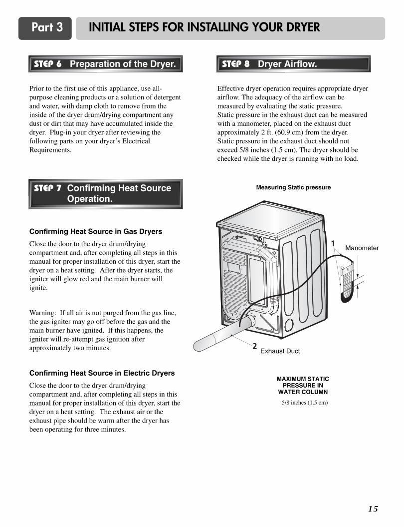
Prior to the first use of this appliance, use all-purpose cleaning products or a solution of detergentand water, with damp cloth to remove from theinside of the dryer drum/drying compartment anydust or dirt that may have accumulated inside thedryer. Plug-in your dryer after reviewing thefollowing parts on your dryer’s ElectricalRequirements.
Effective dryer operation requires appropriate dryerairflow. The adequacy of the airflow can bemeasured by evaluating the static pressure. Static pressure in the exhaust duct can be measuredwith a manometer, placed on the exhaust ductapproximately 2 ft. (60.9 cm) from the dryer. Static pressure in the exhaust duct should notexceed 5/8 inches (1.5 cm). The dryer should bechecked while the dryer is running with no load.
Confirming Heat Source in Gas Dryers
Close the door to the dryer drum/dryingcompartment and, after completing all steps in thismanual for proper installation of this dryer, start thedryer on a heat setting. After the dryer starts, theigniter will glow red and the main burner willignite.
Warning: If all air is not purged from the gas line,the gas igniter may go off before the gas and themain burner have ignited. If this happens, theigniter will re-attempt gas ignition afterapproximately two minutes.
Confirming Heat Source in Electric Dryers
Close the door to the dryer drum/dryingcompartment and, after completing all steps in thismanual for proper installation of this dryer, start thedryer on a heat setting. The exhaust air or theexhaust pipe should be warm after the dryer hasbeen operating for three minutes.
Measuring Static pressure
5/8 inches (1.5 cm)
MAXIMUM STATIC PRESSURE IN
WATER COLUMN
STEP 6 Preparation of the Dryer. STEP 8 Dryer Airflow.
STEP 7 Confirming Heat SourceOperation.
Manometer
Exhaust Duct
Part 4 ACCESSORIES INSTALLATION
1 6
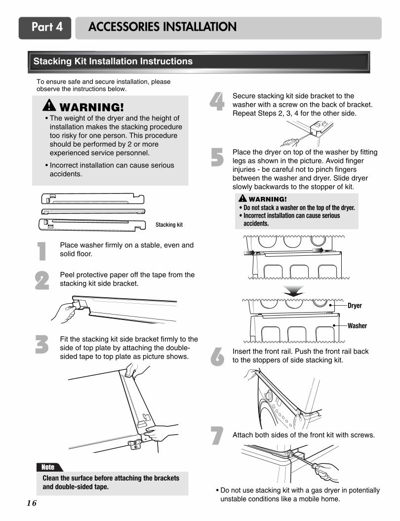
To ensure safe and secure installation, pleaseobserve the instructions below.
Place washer firmly on a stable, even andsolid floor.
Peel protective paper off the tape from thestacking kit side bracket.
Fit the stacking kit side bracket firmly to theside of top plate by attaching the double-sided tape to top plate as picture shows.
Secure stacking kit side bracket to thewasher with a screw on the back of bracket.Repeat Steps 2, 3, 4 for the other side.
Place the dryer on top of the washer by fittinglegs as shown in the picture. Avoid fingerinjuries - be careful not to pinch fingersbetween the washer and dryer. Slide dryerslowly backwards to the stopper of kit.
Insert the front rail. Push the front rail backto the stoppers of side stacking kit.
Attach both sides of the front kit with screws.
• Do not use stacking kit with a gas dryer in potentiallyunstable conditions like a mobile home.
Stacking kit
12
3
4
5
6
7
Stacking Kit Installation Instructions
Clean the surface before attaching the bracketsand double-sided tape.
WARNING!
Note
• The weight of the dryer and the height ofinstallation makes the stacking proceduretoo risky for one person. This procedureshould be performed by 2 or moreexperienced service personnel.
• Incorrect installation can cause seriousaccidents.
WARNING!• Do not stack a washer on the top of the dryer.• Incorrect installation can cause serious
accidents.
Dryer
Washer
1 7
Part 4 ACCESSORIES INSTALLATION
Pedestal Installation Instructions
The pedestal accessory includes:• Drawer divider (1) • Wrench (1)
• Screws (18) † • Retainers (4) ††
Tools Needed for Installation:• Phillips-head screwdriver
• Wrench (supplied)
† Dryer installation only uses 8 screws†† For dryer only
To ensure safe and secure installation, pleasethoroughly follow the instructions below.
Retract fully
Retainer
T-clip
Then loosen1-1/2 turns
1 To set the dryer to the same height as thewasher, fully retract the leveling feet of thedryer by turning them counterclockwise, thenturn them clockwise 1-1/2 turns.NOTE: The appliance and pedestal assemblymust be placed on a solid, sturdy, level floorfor proper operation.
2 Insert the T-clip of the 4 retainers into the dryerbase as shown. Press up on the back of theclip and pull outward to lock into place.
3 Place the dryer on thepedestal. Make surethe front and back feet are in the correctpositions. The dryerfeet will fit into theinnermost positions asshown.
4 Make sure the screws on the pedestal align with the holes in the retainers, then install 4 screws ateach corner to securely attach the appliance to thepedestal.NOTE: If the screws are not installed properly, noiseand vibration may result.Move the appliance to the desired location.
6 Securely tighten all locknuts by hand. NOTE: Noise and vibration may result if locknuts are nottightened. Be sure to connect the appliances to all water, power, or gas lines and draining or venting connections beforeoperation. If there is excessive vibration during the first operationafter installation, slightly adjust the leveling feet.
5 Loosen the locknuts on all 4 leveling feet of thepedestal until you can turn them with the wrench.Turn clockwise to raise or counterclockwise to loweruntil the pedestal is level and all 4 feet are solidlyagainst the floor.
For dryer
For washer/combo
Raise Lower
Locknut
1 8
Part 5 ELECTRICAL REQUIREMENTS FOR ELECTRIC DRYERS
The following are additional instructions regarding electrical connections and requirements for electric dryers.
Warning: The wiring and grounding must conform to the latest edition of the National Electrical Code,ANSI/NFPA 70 and all applicable local regulations. Please contact a qualified electrician to check your home’swiring and fuses to ensure that your home has adequate electrical power to operate the dryer. Failure to do so canresult in fire or electrical shock.
120V/ 240V, 60 Hertz, 3-Wire Installation
Instructions for Grounding of your ElectricDryer:
a) This dryer must be connected to a groundedmetal, permanent wiring system or anequipment-grounding conductor must be runwith the circuit conductors and connected to theequipment-grounding terminal or lead on thedryer.
b) The dryer has its own terminal block that mustbe connected to a separate 60 Hertz singlephase AC circuit, fused at 30 Amperes (thecircuit must be fused on both sides of the line).ELECTRICAL SERVICE FOR THE DRYERSHOULD BE OF MAXIMUM RATEVOLTAGE LISTED ON THE NAMEPLATE.DO NOT CONNECT DRYER TO 110, 115,OR 120 VOLT CIRCUIT.
c) If branch circuit to dryer is fifteen feet (4.50 m)or less in length, use U.L. (UnderwritersLaboratories) listed No. 10 A.W.G. wire (copperwire only), or as required by local codes. If overfifteen feet (4.50 m), use U.L. (UnderwritersLaboratories) listed No. 8 A.W.G. wire (copperwire only), or as required by local codes. Allowsufficient slack in wiring so dryer can be movedfrom its normal location when necessary.
d) The power cord (pigtail) connection betweenwall receptacle and dryer terminal block IS NOTsupplied with dryer. Type of pigtail and gauge ofwire must conform to local codes and withinstructions mentioned on the following pages.
e) The method of wiring the dryer is optional andsubject to local code requirements. Refer toexamples on next page.
f) You must select the method by which to wireyour dryer according to local code and ordinancerequirements. Sample methods are included inthe following pages.
1 9
Part 5 ELECTRICAL REQUIREMENTS FOR ELECTRIC DRYERS
Use the instructions in this section if your home hasa 3-wire receptacle (NEMA type 10-30R) and youwill be using a UL listed, 120/240 volt minimum,30 amp, dryer power supply cord.
Review the following options to determine the appropriate electrical connectionfor your home:
If this type is available at your home. you will beconnecting to a fused disconnect or circuit breakerbox.
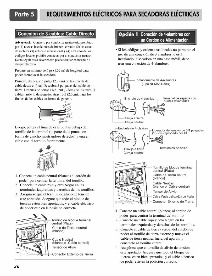
Warning : Grounding through the neutral conductor isprohibited for (1) new branch-circuit installations, (2)mobile homes, (3) recreational vehicles, and (4) areaswhere local codes prohibit grounding through theneutral conductor. Failure to do so can result in fire orelectrical shock.
Prepare minimum 5 ft (1.52 m) of length in order fordryer to be replaced.
First, peel 5 inches (12.7 cm) of covering material fromend. Strip 5 inches of ground wire insulation. Aftercutting 11/2 inch (3.8 cm) from 3 other wires peelinsulation back 1 inch (2.5 cm). Make ends of 3 wires ahook shape.
Then, put the hooked shape end of the wire under thescrew of the terminal block (hooked end facing to theright) and pinch the hook together and screw tightly.
Use the instructions in this section if your home hasa 4-wire receptacle (NEMA type 14-30R) and youwill be using a UL listed, 120/240 volt minimum,30 amp, dryer power supply cord.
If this type is available at your home. you will beconnecting to a fused disconnect or circuit breakerbox.
1. Connect neutral wire (white) of power cord to centerterminal block screw.
2. Connect red and black wires to the left and rightterminal block screws.
3. Connect ground wire (green) of power cord to externalground screw and move neutral ground wire ofappliance and connect it to center screw.
4. Make sure that the strain relief screw is tightened. Be sure that all terminal block nuts are on tight andpower cord is in right position.
3-wire direct
4-wire receptacle (NEMA type14-30R)
3-wire receptacle (NEMA type10-30R)
4-wire direct
4-wire connection : Direct wire
• Connect the power supply wire to the terminalblock. Colored wire should be connected tosame color screw. Wire color indicated onmanual is connected to the same color screw inblock. Otherwise,a short or excessive currentflow may result.
Note
Part 5 ELECTRICAL REQUIREMENTS FOR ELECTRIC DRYERS
2 0
Warning : Grounding through the neutral conductoris prohibited for (1) new branch-circuit installations,(2) mobile homes, (3) recreational vehicles, and (4)areas where local codes prohibit grounding through theneutral conductor. Failure to do so can result in fire orelectrical shock.
Prepare minimum 5 ft (1.52 m) of length in orderfor dryer to be replaced.
First, strip 3 1/2 inches (8.9 cm) of outer sheath fromend and strip 1 inch of insulation from eachconductor.
1. Connect neutral wire (white) of power cord tocenter terminal block screw.
2. Connect red and black wires to the left and rightterminal block screws.
3. Make sure that the strain relief screw is tightened.Be sure that all terminal block nuts are on tightand power cord is in right position.
Then, put the hooked shape end of the wire underthe screw of the terminal block (hooked end facingrightward) and pinch the hook together and tightenthe screw securely.
3-wire connection : Direct wire
1. Connect neutral wire (white) of power cord tocenter terminal block screw.
2. Connect red and black wires to the left and rightterminal block screws.
3. Connect ground wire (green) of power cord toexternal ground screw and move neutral groundwire of appliance and connect it to center screw.
4. Make sure that the strain relief screw is tightened.Be sure that all terminal block nuts are on tightand power cord is in right position.
• lf your local codes or ordinances do not allow theuse of a 3-wire connection, or you are installingyour dryer in a mobile home, you must use a 4-wire connection.
Option 1: 4-wire connection witha power supply cord.
2 1
1. Connect neutral wire (white) of power cord tocenter terminal block screw.
2. Connect ground wire of appliance and neutralwire of power cord to center terminal blockscrew.
3. Connect red and black wires to the left and rightterminal block screws.
4. Make sure the strain relief screw is tightened. Be sure that all terminal block nuts are on tightand power cord is in right position.
5. Connect a independent ground wire from externalground connector to proper ground.
Part 5 ELECTRICAL REQUIREMENTS FOR ELECTRIC DRYERS
lf your local codes or ordinances permit theconnection of a frame-grounding conductor to theneutral wire, use these instructions. If your localcodes or ordinances do not allow the connection ofa frame-grounding conductor to the neutral wire,use the instructions under Section 1: Optional 3-wire connection.
Option 2: 3-Wire connection witha power supply cord.
• If your local codes or ordinances do not allow theconnection of a frame-grounding conductor to theneutral wire, use the instructions under thissection.
Option 3: Optional 3-wireconnection.
Section 1
Part 6 ELECTRICAL REQUIREMENTS FOR GAS DRYERS
120 Volt, 60 Hertz, with 3-Prong Grounding Plug
Following are additional instructions regarding electrical connections and requirements for gas dryers.
Warning: The wiring and grounding must conform to the latest edition of the National Electrical Code,ANSI/NFPA 70, or the Canadian Electrical Code, CSA C22.1, and all applicable local regulations. Please contact aqualified electrician to check your hom’s wiring and fuses to ensure that your home has adequate electrical powerto operate the dryer. Failure to do so can result in fire or electrical shock.
Electrical Requirements for Your Dryer:
a) Please note that the wiring diagram is providedinside the dryer control hood. Label all wiresprior to disconnection when servicing the dryer,because wiring errors can cause serious injury toyou and your dryer.
b) Your dryer is designed to be used on a separatebranch, polarized, three-wire, effectivelygrounded, 120 Volt, 60 Hertz, AC (alternatingcurrent) circuit protected by a 15 Ampere fuse,equivalent fuse or circuit breaker.
c) Use separately fused circuits for washers anddryers, and DO NOT operate a washer and adryer on the same circuit.
a) The dryer has a three-prong plug to help guardagainst shock. The plug should be pluggeddirected into a properly grounded three-prongreceptacle that is rated 120 Volts AC (alternatingcurrent) 15 Amps. This plug, in order to beproperly and fully effective, must be plugged intoa properly installed outlet that is grounded inaccordance with all local codes and ordinances.
b) The dryer must be grounded in order to reducethe risk of electric shock, including amalfunction or breakdown.
c) If your laundry room does not meet thespecifications required by this manual, or if youare uncertain whether or not your laundry roommeets these specifications, please have aqualified service person or company. Review your laundry room’s electrical supply forany problems.
WARNING!• Do not overload the circuit by operating
other appliances on the same circuit whenthis appliance is operating, by using anextension cord to connect the dryer to thepower source, or by using any adapter toallow additional cords to connect to thesame outlet.
• Failure to do so can result in fire orelectrical shock.
STANDARD 120 VOLT, 60 HERTZ, 3-WIREEFFECTIVELY GROUNDED CIRCUIT
the dryer. If it does not fit the outlet in yourlaundry room, a proper outlet will need tobe installed in your laundry room by aqualified service person or company.
• Failure to do so can result in fire orelectrical shock.
2 2
2 3
Part 7 GAS REQUIREMENTS AND INSTRUCTIONS
Following are important instructions and information concerning the requirements for the gas supply and service forgas dryers. Warning: The gas supply and service for a gas dryer must comply with all local codes andordinances. In the absence of any local codes or ordinances in your area, the gas supply and service for your gasdryer must comply with the latest edition of the National Fuel Gas Code, ANSI Z223.1/NFPA 54. Failure to do so canresult in death, explosion, or fire.
1. Gas supply requirements: Liquefied Petroleum(L.P.) Gas (2,500 Btu/ft3 (93.1 MJ/m3)) servicemust be provided at 10 + 1.5 in. water columnpressure.
2. Do not attempt to connect the dryer to LiquifiedPetroleum (LP Gas) Gas service without aqualified professional.
3. Isolate the dryer from the gas supply pipingsystem by closing its individual manual shut-offvalve during any pressure testing of the gassupply system at test pressure equal to or lessthan 2/1 psi (3.45 kPa).
4. Supply Line Requirements. Your laundry roommust have a rigid gas supply line to your dryer.In the United States, an individual manual shutoffvalve MUST be installed within at least 6 feet(1.8 m) of the dryer, in accordance with theNational Fuel Gas Code ANSI Z223.1. A 1/8 in.N.P.T. pipe plug must be installed as shown.
5. If using a rigid pipe, the rigid pipe should be 1/2inch IPS. If acceptable under local codes andordinances and when acceptable to your gassupplier, 3/8 inch approved tubing may be usedwhere lengths are less than 20 feet (6.1 m).Larger tubing should be used for lengths inexcess of 20 feet (6.1 m). It is also important thatyou use pipe joint compound that is insoluble inLP gas.
6. To reduce the danger of gas leaks, explosion, andfire, please follow and observe the followinginstructions and WARNINGS.
• Connect the dryer to the type of gas shown on thenameplate.
• Use new flexible stainless steel connectors.
• Use Teflon tape and pipe joint compoundinsoluble in LP gas on all pipe threads.
• Purge gas supply of air and sediment beforeconnecting the gas supply to the dryer in order toprevent gas valve contamination. Beforetightening connection between gas supply anddryer, purge remaining air until odor of gas isidentified.
• DO NOT use an open flame to inspect for gasleaks; instead use a non-corrosive leak detectionfluid.
WARNING!• Use a new AGA or CSA approved gas
supply line.
• Install a shut-off valve.
• Securely tighten all gas connections.
• If connected to LP, have a qualified personmake sure gas pressure does not exceed 13 in. water column.
• Examples of a qualified person includelicensed heating personnel, authorized gascompany personnel, and authorized servicepersonnel.
• Failure to do so can result in death,explosion, or fire.
WARNING!• DO NOT attempt any disassembly of the
dryer. Any disassembly requires theattention and tools of an authorized andqualified service person or company.
• Failure to do so can result in death,explosion, or fire.
2 4
Part 8 EXHAUST REQUIREMENTS AND MAINTENANCE
Following are important instructions and information concerning the exhaust requirements for your dryer. Warning: DO NOT exhaust dryer air into an enclosed and unventilated area, such as an attic, wall, ceiling,
crawl space, chimney, gas vent, or concealed space of a building. To reduce the risk of fire, DO NOT exhaust thedryer with plastic or thin foil Ducting. Failure to do so can result in death, explosion, or fire.
Exhaust Requirements and Instructions:
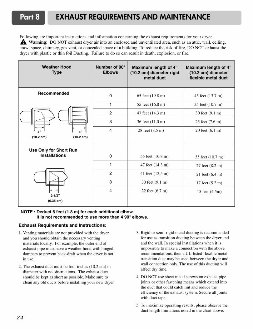
1. Venting materials are not provided with the dryerand you should obtain the necessary ventingmaterials locally. For example, the outer end ofexhaust pipe must have a weather hood with hingeddampers to prevent back-draft when the dryer is notin use.
2. The exhaust duct must be four inches (10.2 cm) indiameter with no obstructions. The exhaust ductshould be kept as short as possible. Make sure toclean any old ducts before installing your new dryer.
3. Rigid or semi-rigid metal ducting is recommendedfor use as transition ducting between the dryer andand the wall. In special installations when it isimpossible to make a connection with the aboverecommendations, then a UL-listed flexible metaltransition duct may be used between the dryer andwall connection only. The use of this ducting willaffect dry time.
4. DO NOT use sheet metal screws on exhaust pipejoints or other fastening means which extend intothe duct that could catch lint and reduce theefficiency of the exhaust system. Secure all jointswith duct tape.
5. To maximize operating results, please observe theduct length limitations noted in the chart above.
Number of 90°Elbows
Weather HoodType
Recommended
Maximum length of 4”(10.2 cm) diameter rigid
metal duct
Maximum length of 4”(10.2 cm) diameterflexible metal duct
NOTE : Deduct 6 feet (1.8 m) for each additional elbow. It is not recommended to use more than 4 90° elbows.
Use Only for Short RunInstallations
0
1
2
3
4
0
1
2
3
4
65 feet (19.8 m)
55 feet (16.8 m)
47 feet (14.3 m)
36 feet (11.0 m)
28 feet (8.5 m)
45 feet (13.7 m)
35 feet (10.7 m)
30 feet (9.1 m)
25 feet (7.6 m)
20 feet (6.1 m)
55 feet (16.8 m)
47 feet (14.3 m)
41 feet (12.5 m)
30 feet (9.1 m)
22 feet (6.7 m)
35 feet (10.7 m)
27 feet (8.2 m)
21 feet (6.4 m)
17 feet (5.2 m)
15 feet (4.5m)
4”
(10.2 cm)
4”
(10.2 cm)
2-1/2”
(6.35 cm)
2 5
Part 8 EXHAUST REQUIREMENTS AND MAINTENANCE
Exhaust and Dryer Maintenance
1. After one year of use, the interior and completeexhaust system of the dryer should be examinedand cleaned if necessary.
2. Before one year of use, when drying performance has becomeunsatisfactory, please examine and clean the exhaust duct forbetter drying performance.
3. Check the weather hoods frequently to ensurethe dampers are moving freely, that the dampersare not pushed in and that nothing has been setagainst the dampers.
4. A qualified service person or company should beused to perform this maintenance.
5. A Flexible Metal Vent Kit, available at extra cost,can be used to exhaust the dryer when it is placedin hard to reach places. This Kit comes in twopieces, one of which is attached to the dryer andthe other is attached to the wall exhaust outlet.Following attachment of the two separate piecesto the dryer and the wall, the dryer may bereturned to its final position, after which the twopieces themselves can be connected.
7. Ordinarily, the dryer drum will need no care.Wipe the exterior of the dryer as required, andalways wipe the exterior of the dryer in the eventany detergent, bleach, or other washing productsis spilled on the dryer.
8. Clean the control panel with a damp cloth asnecessary. Warning: spray pre-wash productsmay damage the finish of the control panel.
9. Please clean the lint filter either before dryingeach load or after drying each load.
10. Always make sure the lint filter is clean beforestarting a new load, because a clogged lint filtermay increase drying times.
11. Annually remove the lint filter and attach it tothe vacuum duct. See item #2 above.
12. Please note that the wiring diagram is providedinside the dryer control hood. Label all wiresprior to disconnection when servicing the dryer,because wiring errors can cause serious injuryto you and your dryer.
Cleaning the Lint Screen
1. Clean the lint filter either before drying each loador after drying each load. Always make sure thelint filter is clean before starting a new load,because a clogged lint filter may increase dryingtimes.
2. To clean, pull the lint screen straight up and rollany lint off the screen with your fingers. Do not rinse or wash screen to remove lint. Pushthe lint screen firmly back into place.
3. Always ensure the lint screen is firmly securedbefore running the dryer. Running the dryer witha loose lint screen may cause overheating anddamage to the dryer and articles being dried.
4. Some articles of clothing may shed more lint thanothers (towels for example), causing the lintscreen to fill rapidly. Remove lint from the lintscreen before and after drying these articles, suchas new towels.
5. In the event lint falls off of the lint screen andinto the dryer during removal, inspect the exhausthood and remove any lint.
6. Laundry detergent and fabric softener residue canbuild up on the lint screen, causing longer dryingtimes. The screen is likely blocked if lint falls offthe screen. In order to prevent this type of buildup, and help ensure proper operation of yourdryer, clean the lint screen with a nylon brushevery six months or, if necessary, morefrequently. The lint filter can also be washed asfollows:
a) After rolling the lint off of the screen with yourfingers, wet both sides of the screen with hot orwarm water.
b) Wet a nylon brush with hot water and liquiddetergent and scrub the lint screen with the brushto remove the buildup of detergent and fabricsoftener.
c) After the residue has been removed, rinse screenwith hot water.
d) After drying the lint screen with a clean towel,firmly replace the lint screen in your dryer.
WARNING!• Disconnect the dryer’s electric power
prior to any cleaning or maintenance.
• Failure to do so can result in fire orelectrical shock.
2 6
Part 9 OPERATING YOUR DRYER
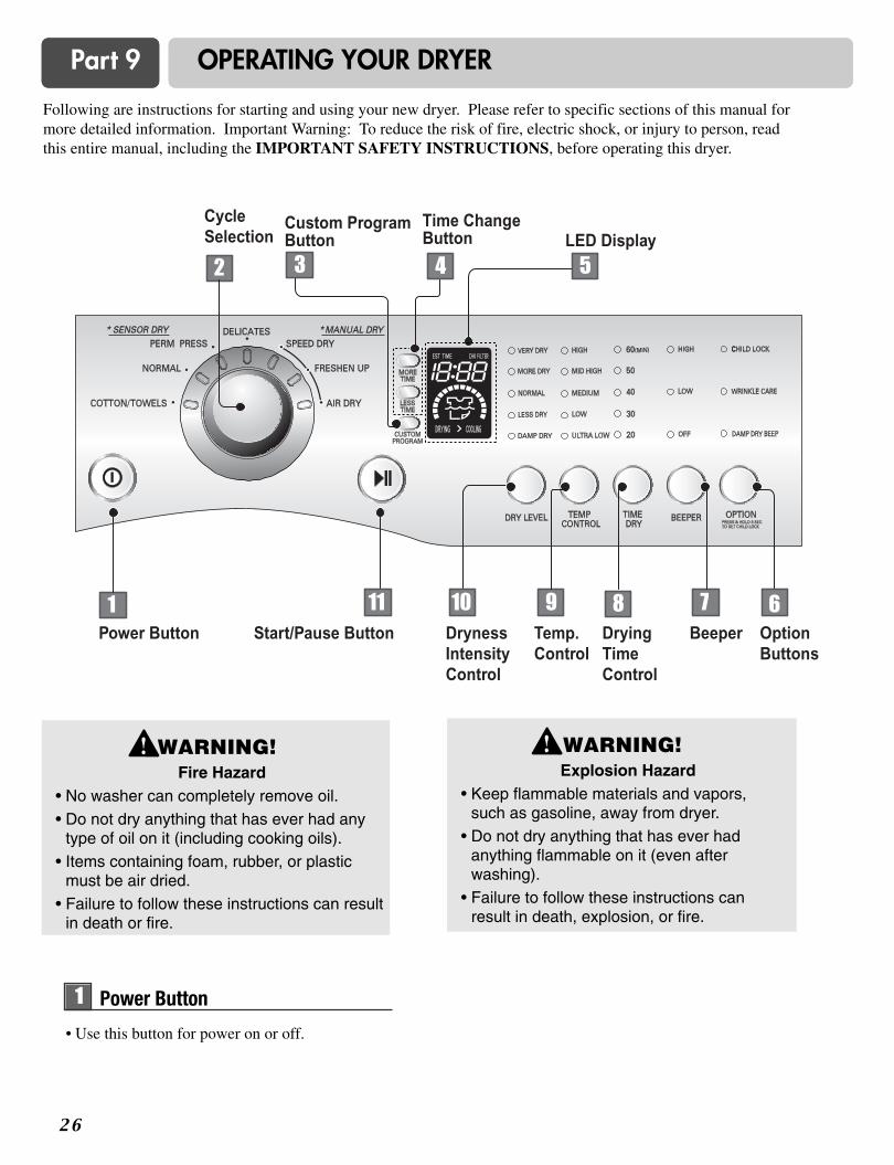
Following are instructions for starting and using your new dryer. Please refer to specific sections of this manual formore detailed information. Important Warning: To reduce the risk of fire, electric shock, or injury to person, readthis entire manual, including the IMPORTANT SAFETY INSTRUCTIONS, before operating this dryer.
WARNING!Fire Hazard
• No washer can completely remove oil.• Do not dry anything that has ever had any
type of oil on it (including cooking oils).• Items containing foam, rubber, or plastic
must be air dried. • Failure to follow these instructions can result
in death or fire.
WARNING!Explosion Hazard
• Keep flammable materials and vapors,such as gasoline, away from dryer.
• Do not dry anything that has ever hadanything flammable on it (even afterwashing).
• Failure to follow these instructions canresult in death, explosion, or fire.
• Use this button for power on or off.
11 Power Button
2 7
Part 9 OPERATING YOUR DRYER
• Turn the knob to select the desired cycle based onlaundry types and conditions.
22 Cycle Selection22 Cycle Selection
Sensor Dry Cycles allow you to match the cycle tothe load you are drying. Each cycle dries certainfabrics at the recommended temperature. A sensordetects the moisture in the load and automaticallyadjusts the drying time for optimal drying
Cotton/TowelsUse for drying denims, towels, heavy cottons.
NormalUse for drying sturdy fabrics such as work casualclothes.
Perm. PressUse for permanent press and synthetic items.
DelicatesUse for drying synthetic fabrics, washable knitfabrics and no-iron finishes.
1. Sensor Dry Cycles
2. Manual Dry Cycles
Use Manual Cycles to select a specific amount ofdrying time and a drying temperature. When aManual Cycle is selected, the ESTIMATED TIMEREMAINING display shows the actual timeremaining in your cycle. You can change the actualtime in the cycle by pressing MORE TIME or LESSTIME.
Speed DryUse for small loads or loads that need a short dryingtime.
Freshen UpUse this cycle to remove wrinkles from items, suchas clothes packed in a suitcase or items wrinkledfrom being left in the dryer too long.
Air DryUse the Air Dry Modifier for items that requiredrying without heat such as rubber, plastic and heat-sensitive fabrics.
Sensor DryCycles Load Type
Temp.
MediumHigh
Medium
Low
Time*(Minutes)
55
41
32
COTTON/TOWELSTowel, denim pants
NORMALWork clothes, corduroys
DELICATESLingerie, sheets, blouses
Sensor Dry Preset Cycle Settings Manual DryCycles Load Type
Temp.
High
Air Dry
Default Time*(Minutes)
25
30
SPEED DRYSMALL LOADS
AIR DRY
Manual Preset Cycle Settings
Low 36PERM. PRESSSynthetics , permanentpress
MediumHigh
20FRESHEN UPRemove Wrinkles
2 8
Part 9 OPERATING YOUR DRYER
• Press MORE TIME or LESSTIME until the desired dryingtime is set.
Time change button is available only with ManualDry, Time Dry and Rack Dry programs.
Note
44 Time Change Button
55 LED Display
1. CHECK FILTER REMINDER
The display will show CHECK FILTER when thedryer is turned on as a reminder to check the filter. It turns off when the START/PAUSE button is pressed.
2. Estimated Time Remaining
The display shows the estimated time remaining.In addition to this, if the dryer has some problem, itdisplays error messages.
3. CYCLE COMPLETION INDICATOR
Shows how much of the current drying cycle has beencompleted.
4. STATUS/CYCLE DISPLAY
This portion of the display shows the selected cycle,operating status, and special messages. If a cycle hasspecial instructions, they will also be displayed in thisarea.
WARNING!• For better drying performance and safety, clean
lint filter every single use. • Failure to follow these instructions can result in
death or fire.
33 Custom Program
1. Select a cycle.2. Change DRY LEVEL and TEMP. CONTROL.3. Select OPTIONS you want.4. Press and hold the CUSTOM PROGRAM.
To recall your stored CUSTOM PROGRAMPress CUSTOM PROGRAM button, then pressSTART/PAUSE.
Set up your favoritecombination of settings andsave them here for one-touchrecall.
2 9
1. Child Lock
Child Lock can be used to preventyour children from changing optionson control panel while the dryer isrunning.
When Child Lock is enabled, all thebuttons will be locked and Child Lock glows.To enable Child Lock, Press and hold OPTION for3 seconds, A single beep tone is heard and ChildLock is displayed on the status window.To disable Child Lock, press and hold OPTION for3 seconds again.
66 Option Buttons
2. Wrinkle Care
This option helps to prevent wrinklesin your laundry.
When you select the wrinkle freeoption, the dryer will periodicallytumble for up to three hours after thecycle has completed.
You can use this option in case youcan not remove laundry immediatelyafter drying is done.
3. Damp Dry Beep
When you select the damp dry beep option, a beep willalert you when your load is approximately 80% dry.
This notice will allow you to remove lightweight itemsthat are dry or other items that you may wish to iron.
Part 9 OPERATING YOUR DRYER
The BEEPER controls thevolume of the beep that is madewhen you press any of thebuttons on the control panel.
Press BEEPER to adjust thesound level or turn off thesignal.
Use Temp. Control Option toselect temperatures for the ManualCycles. Press TEMP. CONTROLuntil the desired temperaturesetting glows. Temperaturemodifiers cannot be used with theSensor Dry Cycles.
Use Time Dry Option to changeDrying Time on your own. You can select the desiredoperation time manually bypressing Time Dry buttonbetween 20 to 60 minutes.
88 Time Dry
77 Beeper
99 Temp. Control
3 0
Part 9 OPERATING YOUR DRYER
Type of Load Default Time*(Minutes)
Foam rubber-pillows,padded bras, stuffed toys
20 - 30
20 - 30
40 - 50
10 - 20
Plastic shower curtains,tablecloths
Rubber-backed rugs
Olefin, polypropylene,shear nylon
This chart shows examples of items that can bedried using AIR DRY.
Reset cycle to complete drying, if needed.
• Check to see that coverings are securely stitched.• Shake and fluff pillows by hand periodically
during the cycle.• Dry item completely. Foam rubber pillows are
slow to dry.
NOTE: Air Dry is not available with Sensor DryCycles.
When Using Air Dry
1. Before use• Clean lint screen before or after each cycle.
• Place laundry into dryer and shut door. See Loading.
• Turn the knob to select the drying cycle you want.The preset setting for Sensor Dry Cycles or ManualCycles will glow. The estimated or actual cycle time (inminutes) will show in the display.
2. Loading • Determine load size by the amount of space the load
requires rather than the weight of the load.
• Avoid overloading the dryer.Following these instructions can help reduce your utilitybill, prolong the life of your clothes, and decrease thelikelihood of uneven drying and wrinkle.
3. To use a sensor dry cycle• Select DRY LEVEL to adjust how dry you want
the load. As the cycle runs, the control senses thedryness of the load and adjusts the timeautomatically for the selected dryness level.
• Select the desired options.
• Press START/PAUSE
DRY LEVEL selections can only be made whileusing Sensor Dry Cycles. Selecting MORE Dry orLESS Dry automatically adjusts the sensed timeneeded.
Note
❁ Starting your dryer
• Use these buttons to set dry level
• First, select sensor dry cycle.
• Select dry level to adjust howmuch you want to dry the load.As the cycle runs, the controlsenses the dryness of the loadand adjusts the timeautomatically based on theselected dryness level.
1100 Dry Level
DRY LEVEL selections can only be made whileusing Sensor Dry Cycles. Selecting MORE Dry or LESS Dry automatically adjusts theneeded time which is already sensed.
Following are sample loads for Super CapacityDryers:
3 1
Part 9 OPERATING YOUR DRYER
Clean lint filter
Clean the lint filter after each use and check itbefore use. Not cleaning or emptying the filterwill increase drying time and energyconsumption, therefore dryer life expectancycould be shortened after all.
1.Open the doorand pull the filterstraight up.
1. Wipe out the dooropening. Otherwise,build-ups of dirty andforeign objects willdamage sealing ofdoor.
2. Clean the transparentglass door to keepinside view clearthrough the glass.
Run the fingersacross the filter.
2.Clean the filter using one of the following methods.
Vacuum the lint filter.
Wash the lint screenin warm, soapywater.Dry thoroughly andreplace.
■ Clean the door and its opening
Maintenance
4. To use a manual dry cycle
• Select a Manual Dry Cycle.• Press MORE TIME or LESS TIME until the
desired drying time is displayed. Tap MORE TIMEor LESS TIME and the time will change by 1minute interval.
• Press TEMP. CONTROL until the desiredtemperature indicator glows.
• (OPTIONAL STEP) If desired, select OPTIONS.For more details, see Options.
• Press START/PAUSE. Be sure the door is closed.• If you do not press START/PAUSE within 10
minutes of selecting the cycle, the dryerautomatically shuts off.
• If you wish to end your drying cycle after pressingSTART/PAUSE, press START/PAUSE again.
To stop your dryer at any timePress START/PAUSE or open the door.
5. Pausing or restarting • To pause the dryer at any time:
Open the door or press START/PAUSE.
• To restart the dryerClose the door. Press START/PAUSE.
Drying will continue from where the cyclewas interrupted if you close the door and pressSTART within 10 minutes. If the cycle isinterrupted for more than 10 minutes, the dryerwill shut off. Select new cycle settings beforerestarting the dryer.
Note
The MORE TIME or LESS TIME feature can be usedwith Manual Dry and Time Dry.
Note
2
3
1
3 2
Part 10 TROUBLESHOOTING GUIDE
Troubleshooting TipsSave time and money! Review the charts on the followingpages first and you may not need to call for service.
1. Problem: My Dryer Won’t Start
• Is the dryer plugged in?
• Is the fuse blown, or is the circuitbreaker tripped?
Confirm that the dryer’s plug is securely and completely pushed into the laundryroom’s power outlet.
Check your home’s or laundry room’s fuse box/circuit breaker box and replace thefuse or reset the circuit breaker. (IMPORTANT: electric dryers generally use twofuses or breakers.)
Question What to Do
2. Problem: My Dryer Doesn’t Heat
Question What to Do
• Is the fuse blown, or is the circuitbreaker tripped?
• Is the gas supply or serviceblocked or off?
If the fuse is blown or the circuit breaker tripped, the dryer might tumble but notheat. Check your home’s or laundry room’s fuse box/circuit breaker box and replacethe fuse or reset the circuit breaker. (IMPORTANT: electric dryers generally usetwo fuses or breakers.)
Confirm that the house gas shutoff and the dryer gas shutoff are both fully open.
3. Problem: There Are Greasy Spots On My Clothes.
Question What to Do
• Did you follow the instructions onyour fabric softener product?
• Are you drying clean and dirtyclothes together?
• Were your clothes entirely clean?
Confirm and follow the instructions provided with your fabric softener product.
Make sure to use your dryer to dry only clean items, because dirty items can soilclean clothes placed in the same load or later placed in the dryer drum.
Stains on dried clothes are actually stains that weren’t cleansed during the washingprocess. Please review and confirm that you are following your washinginstructions and that the clothes are being completely cleaned.
4. Problem: My Dryer Displayed An Error Code.
Question
tE1
tE2
What to Do
It is displayed when thermistor is open. In this case, thermistor should be replacedand call a service center.
It is displayed when thermistor is shorted. In this case, thermistor should bereplaced by a service center.
3 3
Part 10 TROUBLESHOOTING GUIDE
6. Problem: There Is Static In My Clothes After Drying
Question What to Do
5. Problem: There Is Lint On My Clothes
Question What to Do
Please refer to the manual section on cleaning the lint filter, and please confirm that thelint filter is clean. It is important that the lint filter is clean before each new load oflaundry.
In order to reduce the amount of lint in a load of laundry, sort lint producers (like afuzzy white cotton towel) separately from clothes that might catch lint (such as a pairof black linen pants).
See comments below under. There Is Static In My Clothes After Drying.
Divide your larger load into smaller loads.
Sometimes a person might forget to take a piece of paper or a tissue out of a pocket,and this paper, tissue, or similar material can cause excess lint in a load of laundry.Confirm that the pockets of pants, shirts, and other articles of clothing are emptybefore washing and drying.
• Is your lint filter full?
• Did you properly sort your load oflaundry?
• Do your clothes have excess staticelectricity?
• Did you overload your dryer?
• Did you place any paper, tissue, orother similar material in the load?
• Did you use fabric softener?
• Did you over dry the load oflaundry?
• Are you drying synthetic, permanentpress and blends?
Try using a fabric softener to reduce static electricity.
Over-drying a load of laundry can cause a build up of static electricity. Try using a fabric softener or adjust your settings and use a shorter drying time.
These materials can cause static to build up in a load of dried clothes. Try using a fabric softener.
7. Problem: The Drying Time Is Not Consistent
Question
• Are you using consistent heatsettings and consistent load sizes?
The drying time for a load will vary depending on the heat setting, the type of heatused (electric, natural or LP gas), the size of the load, the type of fabrics, the wetnessof the clothes and the condition of the exhaust ducts and lint filer.
What to Do
8. Problem: Water Is Found Around The Cabinet Cover When Opening The Door.
Question What to Do
• Is water found around cabinet coverwhen opening the door?
It is not out of order because this is condensed moisture by drying.
3 4
Part 10 TROUBLESHOOTING GUIDE
9. Problem: It Takes Too Long For My Clothes To Dry
Question What to Do
• Did you properly sort your loads oflaundry?
• Are you drying large loads of heavyfabrics?
• Are the dryer controls properly set?
• Is the lint filter clean before eachnew load of laundry?
• Are the exhaust ducts clear andproperly configured?
• Is the fuse blown, or is the circuitbreaker tripped?
• Did you overload your dryer?
• Did you under load your dryer?
Separate heavy weight items from light weight items when creating loads.
Heavy fabrics take longer to dry because they tend to retain more moisture. To helpreduce and maintain more consistent drying times for large and heavy fabrics,separate these items into smaller loads of a consistent size.
Use the appropriate control settings for the type of load you are drying.
Please confirm that the lint filter is clean prior to each new load of laundry.
Confirm through review of the appropriate sections of this manual that the exhaustventing ductwork is properly configured. Confirm that the venting is free ofobstructions. Confirm that the outside wall dampers are moving freely, that thedampers are not pushed in, and that nothing has been set against the dampers.
Check your home’s or laundry room’s fuse box/circuit breaker box and replace thefuse or reset the circuit breaker. (IMPORTANT: electric dryers generally use twofuses or breakers.)
Divide your larger load into a number of smaller loads.
If you are only drying a handful of items, add a few extra pieces to help ensureproper tumbling action.
10. Problem: My Clothes Are Wrinkled
Question What to Do
• Are you over drying your laundry?
• Are you removing your laundryfrom the dryer soon after thedrying cycle is complete?
Over drying a load of laundry can lead to wrinkled clothes. Try a shorter dryingtime, and remove items while they still retain a slight amount of moisture.
Remove your laundry from the dryer after the drying cycle ends and either hang orfold the items.
11. Problem: My clothes are shrinking
Question What to Do
• Are you following the careinstructions for your garment?
To avoid shrinkage, please carefully follow the care and use instructions for yourgarment, because some fabrics will naturally shrink when washed. Other fabricscan be washed but will shrink when dried in a dryer.
12. Problem: RLM (Remote Laundry Monitor)
Question What to Do
• RLM problem See the Owner’s Manual of RLM & PLC modem.
TD-V10247GTD-V14247ETD-V14247G
Gracias por comprar una Secadora LG. Por favor lea sumanual correctamente, ya que contiene informaciòn importante de una instalaciòn segura,Uso y mantenimiento. Guarde el modelo y nùmero de serie yconserve su manual para futuras referencias.
2
CARACTERÍSTICAS DEL PRODUCTO
CONTENIDO
PARTE 1. ESPECIFICACIONES. ........................................................................................................................................................................................................... 3
PARTE 2. GARANTÍA E INSTRUCCIONES DE SEGURIDAD IMPORTANTES .................................................................................................................................. 4
PARTE 3. PASOS INICIALES PARA LA INSTALACIÓN DE SU SECADORA.. ................................................................................................................................ 11
PARTE 4. INSTALACIÓN DE ACCESORIOS...................................................................................................................................................................................... 16
PARTE 5. REQUERIMIENTOS ELÉCTRICOS PARA SECADORAS ELÉCTRICAS ......................................................................................................................... 18
PARTE 6. REQUERIMIENTOS ELÉCTRICOS PARA SECADORAS A GAS..................................................................................................................................... 22
PARTE 7. REQUERIMIENTOS E INSTRUCCIONES SOBRE EL GAS .............................................................................................................................................. 23
PARTE 8. REQUERIMIENTOS Y MANTENIMIENTO SOBRE EL ESCAPE....................................................................................................................................... 24
PARTE 9. USANDO SU SECADORA .................................................................................................................................................................................................. 26
PARTE 10. GUÍA PARA LA SOLUCIÓN DE PROBLEMAS ............................................................................................................................................................... 32
Qué significa secado por sensor o secado por tiempo?
Su secadora le proporciona la posibilidad de programar acciones de secado por sensor o por tiempo.Secado por sensorLa secadora detectará automáticamente la humedad de la colada y determinará el tiempo de funcionamiento necesariobasándose en el nivel de sequedad de la carga y el programa seleccionado. En ocasiones, podrá observar un incrementoo disminución repentinos del tiempo de operación. Si esto ocurriera, será debido a que el sensor detecta la humedad dela colada dentro de un período de tiempo determinado. Un cambio repentino en el tiempo de operación no significa unmal funcionamiento.
Secado por tiempoSignifica que puede programar el tiempo de operación manualmente para completar el secado. Alternativamente, puedeusar esta función para secar la ropa si las prendas aún están húmedas pese a haber terminado un ciclo de secado. El secado por tiempo es más efectivo cuando tenga prendas pesadas u objetos voluminosos como sábanas de camastamaño superdoble o ropa de trabajo gruesa.
1
2
3
4
DESEMPEÑO EXTRAORDINARIOSin mencionar su incomparable gran capacidad, puede beneficiarse por su Eficiencia entiempo, operaciòn silenciosa y su sistema de ahorro de energìa
DISEÑO ARTÕÍSTICOEl moderno Diseño del Panel Frontal y su gran puerta de cristal hacen que su hogar se vea conmàs estilo.
CUIDADO DIGITALEl calentador controla las temperaturas Multi-niveles cuidando mejor sus prendas màs preciadas
USO SENCILLOUna amplia selecciòn de funciones de uso amigables siempre lo harán sentirse más confortablecon las operaciones de su secadora.
3
Parte 1 ESPECIFICACIONES
ACCESORIOS
Kit para Apilar
comprado separadamente
Pedestal
comprado separadamente
Vea la página 16 para su uso Vea la página 17 para su uso
Nombre : Secadora Eléctrica y de Gas
Suministro de Energìa : Favor de consultar la etiqueta de medición
referente a la información detallada
Tamaño : 686 x 761 x 983(mm)
Capacidad de la Secadora : Favor de consultar la etiqueta de medición
referente a la información detallada
Peso : 57.2 kg
Las especificaciones son sujetas a cambio por el fabricante.
Parte 2
4
GARANTÍA E INSTRUCCIONES DE SEGURIDAD IMPORTANTES
BÚSQUEDA DE ASISTENCIA SOBRE LA GARANTÍA
ADVERTENCIA! Para su seguridad, debe seguir las recomendaciones de
este manual. Para reducir el riesgo de incendio o explosión, o choque eléctrico, o paraprevenir daños a la propiedad, lesiones personales, o muerte cuando use su artefacto, sigalas precauciones básicas, incluyendo las siguientes.
Encontrará la garantía de su secadora en la parte final de este manual. El servicio degarantía está disponible contactando con su Centro de Servicio LG más próximo. Si esteproducto se instala y se opera siguiendo las instrucciones de este manual, LG reparará orecambiará cualquier pieza defectuosa en material o mano de obra a lo largo del períodocubierto por la garantía, comenzando desde el día de compra.
Restricción de la Garantía : Si la secadora es utilizada para otro propósito que no sea el usofamiliar privado, toda cobertura de la garantía es efectiva por sólo 90 días.
Necesitará el número de modeloo y de serie completo al solicitar la garantía de servicio. Es necesariala prueba de la compra (ticket o recibo).
Utilice el siguiente espacio para anotar el número de modelo y de serie de su nueva secadora LG.
Modelo Número
Número de Serie
Fecha de Adquisición
Tenga a mano su ticket de compra por comodidad al contactar con el servicio de atención alcliente.
5
Parte 2 GARANTÍA E INSTRUCCIONES DE SEGURIDAD IMPORTANTES
• Lea todas las instrucciones antes de usar la secadora. • Antes de usar, la secadora debe instalarse correctamente según
lo descrito en este manual. • No introduzca artículos expuestos a aceites de cocina en su
secadora. Los artículos contaminados con aceites de cocinapueden contribuir a una reacción química que podría .provocaruna carga y ocasionar un incendio. No seque artículos quepreviamente se hayan limpiado, lavado, empapado, o se hayanmanchado con gasolina, disolventes de la limpieza en seco,otras sustancias inflamables o explosivas puesto que emitenvapores que podrían provocar ignición o estallar.
• No toque la secadora si el tambor se está moviendo. • No repare ni substituya ninguna pieza de la secadora y no intente
realizar tareas de mantenimiento a menos que se recomiendeespecíficamente en esta Guía de cuidado y Uso o en lasinstrucciones publicadas de reparación por parte del usuario queusted entienda y esté capacitado para llevar a cabo.
• No trate de forzar los controles. • Antes de sacar de servicio a la secadora o deshacerse de ella,
quite la puerta del compartimiento de secado..
• No permita que otros niños jueguen cerca de la secadora. Es necesario supervisar estrechamente a los niños cuando lasecadora se utilice cerca de ellos.
• No utilice suavizadores o productos para eliminar la estáticaexcepto cuando sea recomendado por el fabricante delsuavizador o del producto.
• No utilice calor para secar artículos que contengan caucho deespuma o materiales de textura similar al caucho.
• Mantenga el área circundante a la abertura del escape y de losalrededores libre de la acumulación de la pelusa, del polvo, ysuciedad.
• Personal de servicio cualificado debe limpiar el interior de lasecadora y del escape periódicamente.
• No instale ni almacene la secadora en un lugar en el cual quedeexpuesta a las condiciones atmosféricas.
• No toque la secadora mientras las piezas se estén moviendo. • Compruebe siempre el interior de la secadora para verificar si
hay objetos extraños. • Limpie la pelusa de la pantalla antes o después de cada carga.
Su seguridad y la de otros es muy importante.
PRECAUCIONES BÁSICAS DE SEGURIDAD.
GUARDE ESTAS INSTRUCCIONES
PELIGRO Si no cumple con las instrucciones de inmediato puede correr peligro de muerte o de lesiones graves.
No cumplir las instrucciones puede ocasionarle la muerte o lesiones graves.!!
Para reducir el riesgo de incendio, descarga eléctrica o daños a usuarios del aparato,siga las precauciones básicas, incluidas las siguientes:
ADVERTENCIA
ADVERTENCIA
Hemos incluido muchos mensajes de seguridad importantes en este manual y en el aparato.Lea y cumpla en todos los casos estos mensajes de seguridad.
Todos los mensajes de seguridad le informarán de peligros potenciales, cómo reducir lasposibilidades de riesgo, y le informarán qué pasaría si no se siguen las instrucciones.
Éste es el símbolo de alerta de seguridad. Este símbolo le alerta de los peligros que podrían matarle a usted o a otros. Todos los mensajes de seguridad aparecerán después del símbolo de alerta y la palabra"PELIGRO" o "ADVERTENCIA". Estas palabras significan:
LEA TODAS LAS INSTRUCCIONES ANTES DE UTILIZAR Por su seguridad, la información de este manual debe seguirse para reducir al mínimo el riesgo deincendio o explosión, descargas eléctricas, o para evitar daños a la propiedad, lesiones personaleso pérdida de vida humana.
ADVERTENCIA
• No guarde ni use gasolina ni otros vaporesinflamables ni líquidos en las cercanías deeste u otro electrodoméstico.
• La instalación y el servicio se deben serllevadas a cabo por parte de un instaladorcualificado, agencia de servicio, o elsuministrador del servicio de gas.
Parte 2 GARANTÍA E INSTRUCCIONES DE SEGURIDAD IMPORTANTES
6
LEA TODAS LAS INSTRUCCIONES ANTES DE UTILIZAR
Por su seguridad, la información de este manual debe seguirse para reducir al mínimo el riesgo deincendio o explosión, descargas eléctricas, o para evitar daños a la propiedad, lesiones personaleso pérdida de vida humana.
ADVERTENCIA
INSTRUCCIONES PARA LA TOMA ATIERRA Este aparato debe tener una toma a tierraadecuada. En caso de un malfuncionamiento o avería, disponer de tomaa tierra reducirá el riesgo de descargaseléctricas proporcionando una trayectoria demenor resistencia para la corriente eléctrica.Este aparato debe ir equipado con un cableque tenga un conductor de toma a tierra delequipo y un enchufe con toma a tierra. El enchufe debe ir conectado en untomacorriente apropiado debidamenteinstalado y con una toma a tierra quecumpla todos los códigos y ordenanzaslocales.
ADVERTENCIA - La conexión incorrecta delconductor de toma a tierra del equipo puededar lugar a un riesgo de descarga eléctrica.Compruebe con un electricista cualificado o unpersonal del servicio si duda de si el aparatodispone de una toma a tierra correcta. No modifique el enchufe proporcionado con elaparato. Si no cabe el enchufe en el tomacorriente,solicite a un electricista cualificado lainstalación de un enchufe apropiado. Este aparato debe conectarse a un metal contoma a tierra, sistema permanente decableado o debe tenderse un conductor detoma a tierra del equipo con conductores delcircuito y conectarse al terminal de toma atierra del equipo o hacia el aparato.
PRECAUCIONES BÁSICAS DE SEGURIDAD.
Para reducir el riesgo de incendio, descarga eléctrica o daños a usuarios del aparato,siga las precauciones básicas, incluidas las siguientes:
ADVERTENCIA
7
Parte 2 GARANTÍA E INSTRUCCIONES DE SEGURIDAD IMPORTANTES
1. No intente encender un fósforo ni uncigarrillo, ni ponga en marcha ningúnaparato de gas o eléctrico.
2. No toque ningún interruptor eléctricos. No utilice ningún teléfono de su edificio.
3. Despeje la sala, el edificio, o el área detodos los inquilinos.
4. Llame inmediatamente a su suministradorde servicio de gas utilizando el teléfono deun vecino. Siga el teléfono delsuministrador del servicio de gas. Siga lasinstrucciones del suministrador del serviciode gas.
5. Si no puede ponerse en contacto con susuministrador del servicio de gas, llame alcuerpo de bomberos.
QUÉ A HACER SI HUELE GAS
Para reducir el riesgo de incendio, descarga eléctrica o daños a personas alutilizar el aparato, siga las precauciones básicas, incluidas las siguientes:
ADVERTENCIA
LEA TODAS LAS INSTRUCCIONES ANTES DE UTILIZAR
Por su seguridad, la información de este manual debe seguirse para reducir al mínimo el riesgo deincendio o explosión, descargas eléctricas, o para evitar daños a la propiedad, lesiones personaleso pérdida de vida humana.
ADVERTENCIA
8
Parte 2 GARANTÍA E INSTRUCCIONES DE SEGURIDAD IMPORTANTES
• La secadora, con toma a tierra adecuada,debe cumplir con todos los códigos yordenanzas en vigor. Siga los detalles delas instrucciones de instalación.
Puede ocurrir una descarga eléctrica si lasecadora no dispone de una toma a tierracorrecta.
• Antes de usar, la secadora debeinstalarse correctamente según lodescrito en este manual.
Puede ocurrir una descarga eléctrica si lasecadora no dispone de una toma a tierracorrecta.
• Instale y almacene la secadora donde noquede expuesta a las temperaturas bajocero ni a la intemperie.
Todas las reparaciones y el mantenimientodeben ser realizadas por un técnico deservicio autorizado excepto allí donde estaGuía del propietario lo recomiende de otramanera. Utilice solamente piezasautorizadas de fábrica. No seguir estaadvertencia puede causar lesiones serias,un incendio, un descarga eléctrica o inclusola muerte.
• No instale la lavadora en espacioshúmedos para reducir el riesgo dedescarga eléctrica.
No seguir esta advertencia puede causarlesiones serias, un incendio, un descargaeléctrica o incluso la muerte.
• Conecte a un circuito de la potencianominal correcta, protegido, y con lapotencia adecuada para evitar unasobrecarga eléctrica.
Un circuito incorrecto puede derretirse,creando una descarga eléctrica y/o riesgode incendios.
• Quite todos los artículos del embalaje yelimine todos los materiales de envíocorrectamente
No hacerlo podría ocasionar la muerte, unaexplosión o quemaduras.
• Coloque la secadora por lo menos 18pulgadas sobre el piso en el caso de unainstalación en un garaje.
No hacerlo podría ocasionar la muerte, unaexplosión o quemaduras.
INSTRUCCIÓN DE SEGURIDAD PARA LA INSTALACIÓN
Para reducir el riesgo de incendio, descarga eléctrica o daños a usuarios delaparato, siga las precauciones básicas, incluidas las siguientes:
ADVERTENCIA
LEA TODAS LAS INSTRUCCIONES ANTES DE UTILIZAR Por su seguridad, la información de este manual debe seguirse para reducir al mínimo el riesgo deincendio o explosión, descargas eléctricas, o para evitar daños a la propiedad, lesiones personaleso pérdida de vida humana.
ADVERTENCIA
9
Parte 2 GARANTÍA E INSTRUCCIONES DE SEGURIDAD IMPORTANTES
• Se recomienda el uso entre la secadora yla pared de un conducto rígido osemirrígido. En especial, en aquellasinstalaciones en las que sea imposiblerealizar una conexión siguiendo lasrecomendaciones antedichas, puedeutilizarse un conducto de transiciónmetal flexible de norma UL entre lasecadora y la conexión de la paredsolamente. El uso de este tipo deconducto afectará al tiempo de secado.
No seguir estas instrucciones puede darlugar a un incendio o incluso la muerte.
• NO utilice los tornillos del metal de hojau otros amarres que se extienden alconducto puesto que podrían recogerpelusa y reducir la eficiencia deldispositivo de escape. Asegure todas lasjuntas con cinta para conductos. Para más detalles, siga las instruccionesde instalación.
No seguir estas instrucciones puede darlugar a un incendio o incluso la muerte.
INSTRUCCIÓN DE SEGURIDAD PARA LA INSTALACIÓN (CONT.) Escape/Conducto:
• Las secadoras de gas SE DEBEN conducirsu escape al exterior.
No seguir estas instrucciones puede dar lugara un incendio o incluso la muerte.
• El dispositivo de escape de la secadora sedebe canalizarse al exterior de la vivienda.
Si la secadora no conduce su escape alexterior, se expulsarán área al área dellavadero algo de pelusa fina y grandescantidades de humedad. Una acumulación depelusa en cualquier área del hogar puedecrear un riesgo a la salud y de incendios.
• Utilice solamente un conducto de metalrígido o metal flexible de 4 pulgadas con undiámetro en el interior del armario de lasecadora o para conducir el escape alexterior.
El uso de plástico o de otro conductocombustible puede causar un incendio. La existencia de orificios en el conducto puedecausar un incendio si queda atrapado enfuncionamiento o durante la instalación
• El conducto no se entrega con la secadora.Usted es el responsable de instalar elconducto necesario en el lugar deinstalación. La tapa del extremo debedisponer de abisagradores conamortiguación para evitar corrientes de airea contraviento cuando la secadora estéparada.
No seguir estas instrucciones puede dar lugara un incendio o incluso la muerte.
• El conducto del escape debe tener 4pulgadas (10 centímetros) de diámetro sinobstrucciones. El conducto del escape debe ser lo mascorto posible. Cerciórese de limpiarcualquier viejo conducto antes de instalarsu nueva secadora.
No seguir estas instrucciones puede dar lugara un incendio o incluso la muerte.
LEA TODAS LAS INSTRUCCIONES ANTES DE UTILIZAR Por su seguridad, la información de este manual debe seguirse para reducir al mínimo el riesgo deincendio o explosión, descargas eléctricas, o para evitar daños a la propiedad, lesiones personaleso pérdida de vida humana.
ADVERTENCIA
Parte 2 GARANTÍA E INSTRUCCIONES DE SEGURIDAD IMPORTANTES
1 0
• Bajo ninguna circunstancia deberá cortaro eliminar la tercera patilla (de toma atierra) del cable de alimentación.
Para evitar lesiones personales o daños a lasecadora, el cable de corriente eléctrica seir conectado debidamente y contar con unatoma a tierra adecuada.
• Por su seguridad personal, estasecadora ha de tener una toma a tierraadecuada.
No hacerlo podría ocasionar descargaseléctricas o lesiones.
• Consulte las instrucciones de instalaciónde este manual para los requisitoseléctricos específicos de su modelo.
No seguir estas instrucciones puede sercausa de una descarga eléctrica y/o unriesgo de incendios.
• Esta secadora ha de ir conectada a untomacorriente con una toma a tierraadecuada
Puede ocurrir una descarga eléctrica si lasecadora no dispone de una toma a tierracorrecta.
• Solicite que un electricista cualificadocompruebe la toma a la pared y elcircuito para asegurarse de que la toma atierra está correctamente realizada.
Esto evitará peligros de descargas y asegurará laestabilidad durante el funcionamiento.
• La secadora siempre ha de ir conectadaa su propio tomacorriente eléctricoindividual con una potencia nominal quecoincida con la de la placa.
Una instalación así proporciona el mejorrendimiento y también evita la sobrecargade los circuitos de cables domésticos, loque podría provocar riesgo de incendiodebido a unos cables recalentados.
• Nunca desenchufe su secadora estirandodel cable de alimentación.
Sujete siempre firmemente el enchufe ysáquelo de la toma sin agitarlo de lado alado.
El cable de alimentación puede cortarsecomo consecuencia de un movimiento delnúcleo, provocando una descarga eléctrica.
• Repare o cambie de inmediato todos loscables de servicio eléctrico que se hayanpelado o dañado. No utilice cables quemuestren grietas o daños por abrasiónpor su extensión o en cualquier extremo.
Un circuito incorrecto puede derretirse,creando una descarga eléctrica y/o riesgode incendios.
• Al instalar o mover la secadora, tengacuidado de no pisar, machacar, o dañarel cable eléctrico.
Esto evitará lesiones y daños a la secadorapor fuego y descargas eléctricas.
INSTRUCCIÓN DE SEGURIDAD PARA LA CONEXIÓN DE ELECTRICIDAD
Para reducir el riesgo de incendio, descarga eléctrica o daños a usuarios delaparato, siga las precauciones básicas incluidas las siguientes:
ADVERTENCIA
LEA TODAS LAS INSTRUCCIONES ANTES DE UTILIZAR Por su seguridad, la información de este manual debe seguirse para reducir al mínimo el riesgo deincendio o explosión, descargas eléctricas, o para evitar daños a la propiedad, lesiones personaleso pérdida de vida humana.
ADVERTENCIA
1 1
Parte 3 PASOS INICIALES PARA LA INSTALACIÓN DE SU SECADORA
Las siguientes instrucciones le servirán de guía a través de los pasos iniciales para la preparación de susecadora para el uso. Por favor note que cada sección de este manual proporciona información importantesobre la preparación y uso de su secadora, y es muy importante que lea este manual completamente antes deproceder con cualquiera instalación o con su uso. Instrucciones detalladas adicionales concernientes a lasconexiones eléctricas, conexiones del gas, y los requerimientos sobre el escape son suministrados en otraspartes de este manual.
Elija un lugar de suelo sólido en el que poder ubicarsu secadora. Colóquela al menos 18 pulgadas sobreel suelo si la instala en un garaje. Una vez lasecadora ha sido instalada en el lugar deseado,asegúrese de que cuenta con las holguras necesariasque puede ver en la siguiente ilustración y en lassecciones de los requisitos de salida y demantenimiento.Si está instalando su secadora en una casaprefabricada o móvil, favor refiérase al PASO 9abajo para instrucciones adicionales.
Son necesarias ciertas holguras mínimas de separaciónarriba, por debajo y a los lados de la unidad, como puedeapreciar en las ilustraciones siguientes. Las holgurasmínimas necesarias son las que marcan las ilustraciones deabajo. Recuerde siempre las instrucciones siguientes alinstalar en un recinto cerrado o hueco.
• Considere dejar más holgura para la instalación y lastareas de servicio.
• La existencia de protuberancias en la pared, puerta o elsuelo puede necesitar de holguras mayores.
• Se recomienda un pulgada adicional de holgura parareducir al mínimo la transferencia de ruido.
• Considere el espacio necesario para loselectrodomésticos que puedan acompañar a éste.
• En las instalaciones en recintos cerrados, la ilustraciónde abajo muestra las aberturas de ventilación mínimasnecesarias para la puerta. Es aceptable también unapuerta con rendijas con aberturas para lograr unaventilación comparable.
* La mayoría de las instalaciones requieren unmínimo de 51/2 pulgadas de espacio libre (14 cm) detrás de la secadora para el conducto deescape con el codo.
PASO 1 Colocación de laSecadora
Vista lateral del ClósetPuerta del Clóset
Agujero deVentilación
Agujero deVentilación
Vista Frontal del Clóset
Debería asegurar las patas niveladoras.Las cuatro patas deben quedar sentadas con totalseguridad en un suelo sólido y nivelado.Si la secadora no está nivelada, la colada podríano dar vueltas debidamente y el sensor nodetectará la humedad correcta.Al ajustar el nivel, tenga cuidado de no lesionarseseriamente los dedos de la mano ni del pie.
Nota
38.7”(98.3 cm)
27”(68.6 cm)
29.96”(76.1 cm)
49.8”(126.4 cm)
1 2
Parte 3 PASOS INICIALES PARA LA INSTALACIÓN DE SU SECADORA
Una vez en posición ajuste las patas niveladoras de lasecadora hasta que esté nivelada de izquierda aderecha y del frente hacia atrás. Las patasniveladoras deben permanecer firmes en el piso y lasecadora no debe mecerse. La máxima inclinación dela secadora de izquierda a derecha o del frente haciaatrás no debe ser mayor de 2.5 cm (1 pulgada). Si lasecadora no está nivelada, y si la inclinación excedelos 2.5 cm (1 pulgada), la carga puede que no gireadecuadamente y los sensores internos pueden nofuncionar correctamente. Nota: Otras secciones deeste manual también proveen información importantesobre la ubicación y los espacios libres para susecadora.Por favor lea este manual completamenteantes de proceder con cualquier instalación.
La puerta de su secadora puede ser instalada demanera que abra hacia la izquierda o hacia laderecha. Siga estos procedimientos para invertir ladirección en que su puerta abre:
PASO 2 Procedimiento paraInvertir la Puerta
La puerta y la bisagra deberían alienarse en elcentro al cerrarse. De lo contrario la puerta secerrará y abrirá mal.
Nota
1
2
3
1 3
Parte 3 PASOS INICIALES PARA LA INSTALACIÓN DE SU SECADORA
Además de las siguientes advertencias, por favorrefiérase a la sección del manual sobre Requerimientos yMantenimientodel Escape. Advertencia: La secadoradebe estar ventilada hacia la intemperie. Por favor sigalas siguientes instrucciones (y todas las otras en estemanual) muy cuidadosamente. Si no cumple con estasinstrucciones puede resultar en muerte o incendio.
• No utilice conductos de plástico o aluminio.• Los conductos metálicos rígidos o semi-rígidos se
recomiendan para usarse como conductos de transiciónentre la secadora y la pared. Especialmente en lasinstalaciones donde es imposible hacer la conexión con lasrecomendaciones anteriores, un conducto metálico flexiblelistado UL puede usarse solamente entre la conexión de lasecadora y la pared. El uso de estos conductos afectará eltiempo de secado.
• Coloque la secadora en tal posiciòn que el ducto corra dela menor forma posible.
• Limpie los ductos viejos antes de instalar esta secadora.• El extremo macho de cada sección del ducto de escape
debe apuntar contrario a la secadora.• Use las menores conyucturas posibles.• Utilice cinta selladora de ductos en todas las uniones de
ductos.• Aísle la instalación de escape que pase a través de áreas sin
calentamiento con el fin de reducir la condensación y laacumulación de pelusas en las paredes de la tubería; y
• POR FAVOR TENGA CUIDADO YA QUE DE NOINSTALAR CORRECTAMENTE EL SISTEMA DEESCAPE ANULARÁ LA GARANTÍA DE LASECADORA
ADVERTENCIA!• Utilice material para ventilación de metal pesado.
• No utilice conductos de plástico o aluminio delgado.
• Si no cumple con estas instrucciones puede resultaren muerte o incendio.
1. Quite el tornillo y el ducto de escape.(Utilice el kit de salida, n° de pieza 3911EZ9131X).
2-1. Separe y extraiga la seguridad de la parte inferior,izquierda o derecha según desee. (La ventilacióndel lado derecho no está disponible en lasecadora a gas). , , es el orden del trabajo.
2-2. Reconecte el otro conducto (11 pulgadas o 28 cm)
al alojamiento del soplador y acople el conducto a
la base.
3-1. Arme previamente un codo de 4 con un ducto de 4".Envuelva la cinta selladora para ducto alrededor de launión.
3-2. Inserte el montaje del ducto, el codo primero através de la abertura lateral y conecte el codo alducto interno de la secadora.
PASO 3 Conexión del Sistemade Escape y Ventilación
El extremo de la ventilación mirará hacia el ladoexterno y el mal roscado o una instalación.inestable de la ventilación provocarán niveles desecado no deseados.
Nota
1 2 3
DIRECCIONES ALTERNAS PARA EL ESCAPE
1 4
Parte 3 PASOS INICIALES PARA LA INSTALACIÓN DE SU SECADORA
(Secadora a Gas solamente). Además de lo siguiente, porfavor refiérase a la sección del manual sobreRequerimientos e Instrucciones del Gas.
1. Confirme que el tipo de gas disponible en su cuarto delavado sea el adecuado para su secadora. La secadoraestá preparada para Gas Natural con una conexión degas NPT de 3/8".
2. Remueva la tapa protectora de la conexión de gasdetrás de la secadora. Asegúrese de no dañar la roscade la tubería de la conexión de gas cuando remueva latapa protectora.
3. Conecte la secadora al suministro de gas en su cuartode lavado utilizando un conector nuevo flexible deacero inoxidable (como se mencionó antes, sólo use unconector nuevo flexible de acero inoxidable si espermitido por códigos locales)
4. Asegúrese de apretar todas las conexiones entre lasecadora y el suministro de gas en su cuarto de lavado.Abra el suministro de gas en su cuarto de lavado yverifique todas las conexiones de la tubería (internas yexternas) para detectar fugas de gas utilizando undetector líquido de fugas no corrosivo.
5. Para una conexión a gas LP (Petróleo Licuado),refiérase a la sección de este manual sobreRequerimientos e Instrucciones del Gas.
1. Conector flexible nuevo de acero inoxidable. Utilice este tipo de conectorsólo si es permitido por los códigos locales. Use un conector de diseño AGACertificado.
2. Conector de tubo NPT de 1/8" (para verificar la presión de entrada de gas)3. Válvula de Cierre de Equipo instalada a una distancia de
6’ (1.8 m) de la secadora.4. Tubería de hierro. Más corta de 20’ (6.1 m) Use tubería de 3/8" . Más larga
de 20’ (6.1 m) - Use tubería de 1/2".5. Conexión de Gas N.P.T de 3/8" .
A continuación encontrará advertencias e instruccionesconcernientes a la confección de la conexión eléctricapara secadoras eléctricas. Información detallada adicionalconcerniente a la conexión eléctrica es suministrada en lasección del manual Requerimientos Eléctricos para laSecadora Eléctrica y es importante que usted lea estasección completamente, así como el resto del manual,antes de tomar algún paso para instalar o usar estasecadora.1. Use solamente un cordón de alimentación nuevo
listado No. 10 por U.L.(alambre de cobre únicamente)de tres conductores clasificado para 240 Voltios(mínimo) 30 Amperios y que está indicado de usoaceptable para una secadora de ropa.
2. Un cordón de 4 alambres es requerido parainstalaciones y uso en casas prefabricadas (móvil) ydonde los códigos locales no permitan conexión atierra de este aparato a través del neutral.
4. Para instrucciones adicionales de como conectar lasecadora a una fuente eléctrica, favor refiérase a lasección de este manual sobre RequerimientosEléctricos para Secadora Eléctrica.
ADVERTENCIA!• Use un cordón de alimentación nuevo aprobado por
U.L. de 30 amp.o alambre de cobre sólido calibre 10.• Use un liberador de tensión aprobado por UL .• Desconecte la corriente antes de hacer las
conexiones eléctricas.• Conecte el alambre neutral (alambre blanco o
central) al terminal central.• El alambre a tierra alambre verde o descubierto)
debe conectarse al conector a tierra verde.• Asegúrese de apretar todas las conexiones
eléctricas.• Vea las instrucciones de instalación para unas
instrucciones completas.• De no seguir estas advertencias puede resultar en
Asegúrese de que la boquilla del zumbador es la adecuadapara el tipo de gas que utiliza.Por ejemplo, usar LPG con una boquilla LNG ocasionaría lamuerte del usuario, el incendio o una explosión. Del mismomodo, LNG con una boquilla LPG no provocarán la ignicióndel quemador.Si fuese necesario, la conversión de la boquilla deberíarealizarla un técnico de servicio cualificado y marcar o ponerla etiqueta del tipo actual de boquilla en la secadora.
Nota
Requisitos de admisión al quemadorSi su casa está situada en alturas hasta los 10.000 pies.Ajustar la admisión al quemador no es necesario en estaselevaciones porque A.G.A. certifica que esta secadora notiene problemas con los rangos BTU a estas alturas.Si su casa está situada a alturas superiores a los 10.000pies, necesitará ajustar un cuatro por cien (4%) dereducción en el quemador, que es el rango indicado por elBTU en la placa de modelo/rango de serie.
Nota
1 5
Parte 3 PASOS INICIALES PARA LA INSTALACIÓN DE SU SECADORA
Antes de usar por primera ves esta secadora, utiliceun producto limpiador para todo propósito, o unasolución de detergente y agua, con un paño húmedopara remover de la parte interior del tambor de lasecadora /compartimiento de secado cualquier polvoo sucio que se haya podido acumular dentro de lasecadora. Enchufe su secadora después de haberrevisado las siguientes partes en los RequerimientosEléctricos de su secadora.
La efectiva operación de la secadora requiere de unflujo de aire adecuado. El flujo de aire adecuadopuede ser medido evaluando la presión estática. Lapresión estática en el ducto de escape puede sermedida con un manómetro, colocado en el ducto deescape aproximadamente a a 2 pies (60.9 cm) de lasecadora. La presión estática en el ducto de escapeno debe exceder 5/8 pulgadas (1.5 cm). La secadoradebe ser verificada cuando está operando sin carga.
Confirmación de la Fuente de Calor enSecadoras a Gas
Cierre la puerta al tambor / compartimiento desecado de la secadora y después de habercompletado todos los pasos de este manual para lainstalación correcta de esta secadora, encienda lasecadora en temperatura caliente, como mejor sedescribe en las instrucciones de operación provistascon la secadora. Después que la secadora seenciende, el encendedor resplandecerá en rojo y elquemador principal encenderá.
Advertencia: Si no todo el aire es purgado fuera dela línea de gas, el encendedor podría apagarse antesde que el gas y el quemador principal se hayanencendido. Si esto sucede, el encendedor intentaráencender el gas después de aproximadamente dosminutos.
Confirmación de la Fuente de Calor enSecadoras Eléctricas
Cierre la puerta al tambor / Compartimiento desecado de la secadora y después de habercompletado todos los pasos en este manual para unainstalación correcta de esta secadora, encienda lasecadora en temperatura caliente, como mejor sedescribe en las instrucciones de operación provistascon la secadora. El aire de escape o el tubo deescape deben calentarse después que la secadorahaya operado por tres minutos.
Medición de la Presión Estática.
5/8 pulgadas (1.5 cm)
PRESIÓN ESTÁTICAMÁXIMA EN
COLUMNA DE AGUA
PASO 8 Flujo de Aire
PASO 7 Confirmación de la Operaciónde la Fuente de Calor.
PASO 6 Preparación de laSecadora
Man ó ro
Ducto de Escape
1 6
Parte 4 INSTALACIÒN DE ACCESORIOS
ADVERTENCIA!• El peso de la secadora y la altura de la
instalaciòn hacen que montar el kit sea peligrosopara una sola persona.
• Este procedimiento debe realizarse por 2 o màspersonas con experiencia en este tipo deservicios.
• Una intalaciòn incorrecta puede causaraccidentes serios.
Instrucciones de Instalaciòn para montar el Kit
Para asegurar una instalaciòn segura, por favorobserve las instrucciones siguientes.
Coloque la lavadora firmemente en unasuperficie estable y sòlida como lasinstrucciones del Manual de Usuarioindican.
Quite el papel protector del kit en el soportelateral.
Asegure el kit en el soporte lateral a lalavadora con un tornillo en la parte traseradel soporte. Repita los pasos 2,3,4 para elotro lado.
Inserte la parte frontal del kit. Empuje laparte frontal hasta el final de los soporteslaterales.
Atornille los lados de la parte frontal del kit.
• No use el kit si existe secado de gas encondiciones Inestables como una casa mòvil.
Kit para Apilar
Encaje el soporte lateral del kit en el ladode la parte superior de la plataformaanexàndole la cinta doble cara en laplataforma como muestra El dibujo.
Coloque la secadora en la parte superior de lalavadora asegurando las patas como se muestraen el dibujo. Evite daños en los dedos- tengacuidado en que no se queden atrapados susdedos entre la lavadora y la secadora. Deslicelentamente la secadora hasta el final del kit.
1
2
3
4
5
6
7Limpie la superficie antes de acoplar lasabrazaderas y la cinta de doble cara.
Nota
Secadora
Lavadora
ADVERTENCIA!• No coloque la lavadora en la parte superior
de la secodora.• Una intalaciòn incorrecta puede causar
accidentes serios.
1 7
Parte 4 INSTALACIÒN DE ACCESORIOS
Instalacion de la secadora (Cinta de tipo doble-cara)
El accesorio de pedestal incluye:• Divisor de cajón (1) • Llave (1)
• Tornillos (18) † • Sujetadores (4) ††
Herramientas necesarias para la instalación:• Destornillador Phillips
• Llave (provista)
† Se necesita 8 tornillos para la secadora†† Para secadora solamente
Para asegurar la instalación segura, sigacuidadosamente las siguientes instrucciones.
Replagadecompletmente
Sujetador
Extremoen T
Luego afloje1-1/2 revoluciones
1 Para ajustar la secadora a la misma altura como lalavadora, asegúrese de que las patas niveladorasde la secadora están replegadas completamentegirándolas en sentido de las agujas del reloj, luegogirándolas en sentido contrario de las agujas delreloj 1-1/2 revoluciones.NOTA: El conjunto del electrodoméstico y elpedestal deben estar colocados en un pisosólido, resistente y nivelado para obtener elfuncionamiento adecuado.
2 Inserte el extremo en T de los 4 sujetadoresdentro de la base de la secadora como semuestra. Presione el extremo trasera hacia arribay tire hacia el exterior para asegurar en su lugar.
3Coloque elelectrodomésticoencima del pedestal.Asegúrese que los piesfrentes y traseros seencuentren en lasposiciones correctas.Las patas de la secadoracoincidirán con lasposiciones extremasinteriores como indicado.
4 Asegúrese de que los orifi cios del pedestal se alineancon los orifi icios de los sujetadores, luego instale 2tornillos en cada esquina para ajustar en forma segura elelec-trodoméstico al pedestal.NOTA: Si los tornillos no se instalan de manera adecuada,es posible que se produzcan ruidos y vibraciones. Mueva elelectrodoméstico hacia la ubicación deseada.
6 Asegure de manera segura las tuercas manualmente.NOTA: Puede haber ruido yvibración si las tuercas no estánaseguradas.Asegúrese de conectar loselectrodomésticos a todas las tuberías de agua o gas o a la fuente de poder o conexiones de ventilación antes de poner en funcionamiento. Si hay vibración excesiva duranteel primer ciclo de funcionamientodespués de la instalación, ajustelevemente las patas niveladoras.
5 Afloje las tuercas en las 4 patas niveladoras delpedestal hasta que pueda girarlos con la llave. Gire enel sentido de las manecillas del reloj o al contrario parabajar hasta vez que el pedestal esté nivelado y todaslas 4 patas estén apoyadas firmemente en el piso.Cómo Usar las Almohadillas para PisoSi instalará el pedestal en un piso de madera, coloquelas almohadillas para piso debajo de las patas delpedestal. Esto ayudará a reducir la vibración cuando lalavadora esté en funcionamiento.
Para la secadora
Para la lavadora/combinación
Raise Bajar
Tuerca
1 8
Parte 5 REQUERIMIENTOS ELÉCTRICOS PARA SECADORAS ELÉCTRICAS
Las siguientes son instrucciones adicionales sobre las conexiones y requerimientos eléctricos para las secadoraseléctricas.
Advertencia: El cableado y la conexión a tierra deben estar de acuerdo con la edición más reciente delcódigo Eléctrico Nacional, ANSI/NFPA 70 y todas las regulaciones locales aplicables. Por favor contacte a unelectricista calificado para verificar el cableado y fusibles de su casa y para asegurar que tiene la energía eléctricaadecuada para el funcionamiento de la secadora. De no seguir estas advertencias puede resultar en incendio ochoque eléctrico.
120V/ 240V, 60 Hertz, Instalación de 3-Alambres
Instrucciones para la Conexión a Tierra desu Secadora Eléctrica:
a) Por favor note que el diagrama de cableado estálocalizado dentro de la cubierta del control de lasecadora.
b) Esta secadora debe ser conectada a un metalcon conexión a tierra, sistema de cableadopermanente, o un conductor equipo-tierra debecorrer con los conductores de circuito y estarconectado al terminal equipo-tierra o líneaprincipal de la secadora.
c) La secadora tiene su propia caja terminal la cualdebe estar conectada a una línea separada,60 Hertz, circuito de fase sencilla, circuito AC(corriente alterna), con fusible de 30 Amperios(el circuito debe tener fusibles en ambos ladosde la línea). EL SERVICIO ELÉCTRICOPARA LA SECADORA DEBE SER DELMÁXIMO RANGO DE VOLTAJE DESCRITOEN LA PLACA. NO CONECTE LASECADORA A UN CIRCUITO DE 110, 115,Ó 120 VOLTIOS.
d) Si la distancia entre la caja de circuito y lasecadora es de 15 pies (4.50 m) o menos, use uncable No. 10 A.W.G. (de cobre únicamente)listado por U.L. (Underwriters Laboratories), ocomo lo requieran los códigos locales. Si es demás de 15 pies (4.50 m), use un cable No. 8A.W.G. (de cobre únicamente) listado por U.L(Underwriters Laboratories) o como lorequieran los códigos locales. Deje suficienteholgura en el cableado de manera que lasecadora pueda ser movida de su posicióncuando sea necesario.
e) La conexión del cordón de alimentación (cableflexible) entre el tomacorriente y la caja terminalde la secadora NO ES suministrada con lasecadora. El tipo del cable flexible y el calibre delalambre deben estar conforme con los códigoslocales y con las instrucciones de las páginassiguientes.
f) El método de cableado de la secadora es opcionaly sujeto a los requerimientos del código local.Refiérase a los ejemplos en la próxima página.
g) Usted debe seleccionar el método para cablear susecadora de acuerdo a los requerimientos de loscódigos locales y ordenanzas. Métodos deejemplo están incluidos en las siguientes páginas.
ADVERTENCIA!• Etiquete todos los cables antes de
desconectarlos para darle mantenimiento ala secadora, ya que errores en el cableadopueden causar lesiones serias a usted ydañar su secadora.
• De no seguir estas advertencias puederesultar en incendio o choque eléctrico.!
1 9
Parte 5 REQUERIMIENTOS ELÉCTRICOS PARA SECADORAS ELÉCTRICAS
Utilice las instrucciones en esta sección si su casatiene un tomacorriente de 3-alambres (Tipo NEMA10-30R) y si usará un cordón de alimentación parasecadora listado por UL, de 120/240 voltios mínimoy de 30 amp.
Revise las siguientes opciones para determinar la conexión eléctrica adecuadapara su casa:
Utilice las instrucciones en esta sección si su casatiene un tomacorriente de 4-alambres (Tipo NEMA14-30R) y si usará un cordón de alimentación parasecadora listado por UL, de 120/240 voltios mínimoy de 30 amp.
Si este tipo està disponible en su casa, lo conectarà auna caja de corto circuito o una pipa desconectada.
Si este tipo està disponible en su casa, lo conectarà auna caja de corto circuito o una pipa desconectada.
Advertencia: Contacto por conductor neutro esta prohibidopor(1) nuevas instalciones de branch- circuito (2) las casas demobiles (3) vehiculo recreacional y (4) areas donde los codigoslocales prohibe contactar por el conductor neutro. De no seguirestas advertencias puede resultar en incendio o choqueeléctrico.
Prepare un mínimo de 5 ps (1.52 m) de longitud para poderreemplazar la secadora.
Primero, despegue 5 pulg (12.7 cm) de la cubierta del cabledesde el final. Descubra 5 pulgadas del cable de tierra. Despuésde cortar 11/2 pul (3.8cm) de los otros 3 cables, aisle lodespegado. atràs 1pul (2.5cm). haga los finales de los cables enforma de gancho.
Luego, ponga el final de esas puntas debajo del tornillo de laterminal (la parte de la punta con forma de gancho mostrandosederecho) y una el cable con el tornillo fuertemente.
1. Conecte un cable neutral (blanco) al cordón de poder para centrarla terminal del tornillo.
2. Conecte un cable rojo y otro Negro en las terminales izquierdas yderechas de los tornillos.
3. Conecte el cable de tierra (verde) del cordón de poder al tornillo detierra externo y mueva el cable de tierra neutral fuera del aparato yconéctelo al tornillo central.
4. Asegúrese que el tornillo de alivio de tensión este apretado.Asegure que todo el bloque de tuercas esten bien apretados, y elcable eléctrico de poder este en la posición correcta.
Tomacorriente de 3-alambres (Tipo NEMA 10-30R)
Tomacorriente de 4-alambres(Tipo NEMA 14-30R).
3-cables directos
4-cables directos
Conexiòn de 4-cables: Cableado directo
• Atornille el cable de la alimentación al bloqueterminal. El cable de color debería conectarse a lostornillos del mismo color. El color del cable indicadaen el manual está conectado al tornillo del mismocolor del bloque. De lo contrario, se aplicará unacorriente excesiva que ocasionará daños al productoy un fallo en la calefacción.
Nota
2 0
Parte 5 REQUERIMIENTOS ELÉCTRICOS PARA SECADORAS ELÉCTRICAS
Advertencia: Contacto por conductor neutro esta prohibidopor(1) nuevas instalciones de branch- circuito (2) las casasde mobiles (3) vehiculo recreacional y (4) areas donde loscodigos locales prohibe contactar por el conductor neutro.De no seguir estas advertencias puede resultar en incendio ochoque eléctrico.
Prepare un mínimo de 5 ps (1.52 m) de longitud parapoder reemplazar la secadora.
Primero, despegue 5 pulg (12.7 cm) de la cubierta delcable desde el final. Descubra 5 pulgadas del cable detierra. Después de cortar 11/2 pul (3.8cm) de los otros 3cables, aisle lo despegado. atràs 1pul (2.5cm). haga losfinales de los cables en forma de gancho.
Luego, ponga el final de esas puntas debajo deltornillo de la terminal (la parte de la punta conforma de gancho mostrandose derecho) y una elcable con el tornillo fuertemente.
1. Conecte un cable neutral (blanco) al cordón depoder para centrar la terminal del tornillo.
2. Conecte un cable rojo y otro Negro en lasterminales izquierdas y derechas de los tornillos.
3. Asegúrese que el tornillo de alivio de tensióneste apretado. Asegure que todo el bloque detuercas esten bien apretados, y el cable eléctricode poder este en la posición correcta.
Conexiòn de 3-cables: Cable Directo Opción 1 Conexión de 4-alambres conun Cordón de Alimentación.
1. Conecte un cable neutral (blanco) al cordón depoder para centrar la terminal del tornillo.
2. Conecte un cable rojo y otro Negro en lasterminales izquierdas y derechas de los tornillos.
3. Conecte el cable de tierra (verde) del cordón depoder al tornillo de tierra externo y mueva elcable de tierra neutral fuera del aparato yconéctelo al tornillo central.
4. Asegúrese que el tornillo de alivio de tensióneste apretado. Asegure que todo el bloque detuercas esten bien apretados, y el cable eléctricode poder este en la posición correcta.
• Si los códigos y ordenanzas locales no permiten eluso de una conexión de 3 alambres, o estáinstalando la secadora en una casa móvil, debeusar una conexión de 4-alambres.
2 1
Parte 5 REQUERIMIENTOS ELÉCTRICOS PARA SECADORAS ELÉCTRICAS
Si los códigos y ordenanzas locales permiten laconexión de un conductor estructura-tierra alalambre neutral, utilice estas instrucciones. Si loscódigos y ordenanzas locales no permiten laconexión de un conductor estructura-tierra alalambre neutral, utilice las instrucciones bajo laSección 1: Conexión opcional de 3-alambres.
Opción 2 Conexión de 3-alambres conun Cordón de Alimentación.
Opción 3 Conexión Opcional de3-alambres.
• Si los códigos y ordenanzas locales no permiten laconexión de un conductor estructura-tierra a uncable neutral, utilice las instrucciones bajo estasección.
1. Conecte un cable neutral (blanco) al cordón depoder para centrar la terminal del tornillo.
2. Conecte el cable de tierra (verde) del cordón depoder al tornillo de tierra externo y mueva el cablede tierra neutral fuera del aparato y conéctelo altornillo central.
3. Conecte un cable rojo y otro Negro en lasterminales izquierdas y derechas de los tornillos.
4. Asegúrese que el tornillo de alivio de tensión esteapretado. Asegure que todo el bloque de tuercasesten bien apretados, y el cable eléctrico de podereste en la posición correcta.
5. Conecte un alambre de tierra independiente delconectador de tierra externo con la tierraapropiada.
Sección 1
2 2
Parte 6 REQUERIMIENTOS ELÉCTRICOS PARA SECADORAS A GAS
120 Voltios, 60 Hertz, con Enchufe de 3-Clavijas con Conexión a TierraLas siguientes son instrucciones adicionales sobre las conexiones y requerimientos eléctricos para las secadoras a gas.
Advertencia: El cableado y la conexión a tierra deben estar de acuerdo con la edición más reciente del códigoEléctrico Nacional, ANSI/NFPA 70, o el Código Eléctrico Canadiense, CSA C22.1, y todas la regulaciones localesaplicables. Por favor contacte un electricista calificado para verificar el cableado y fusibles de su casa y asegurarque tiene la energía eléctrica adecuada para el funcionamiento de la secadora. De no seguir estas advertencias puederesultar en incendio o choque eléctrico.
Requerimientos Eléctricos para su Secadora:!
a) Recuerde que el diagrama de cableado se encuentradentro de la caperuza de control de la secadora.Etiquete todos los cables antes de la desconexión alrealizar tareas de servicio porque errores en elcableado pueden ser causa de serias lesiones parausted y para su secadora.
b) Su secadora está diseñada para ser operada en uncircuito separado, polarizado, de tres alambresefectivamente conectados a tierra, 120 Voltios, 60Hertz, AC (corriente alterna) circuito protegido porun fusible de 15 Amperios, fusetron equivalente odisyuntores.
c) Utilice circuitos de fusibles separados para lalavadora y la secadora, NO opere una lavadora yuna secadora en el mismo circuito.
a) La secadora tiene un enchufe de tres clavijas paraprotección contra choques eléctricos. El enchufedebe ser conectado directamente a un tomacorrientepara tres clavijas debidamente conectado a tierraclasificado para 120 Voltios AC (corriente alterna)15 Amperios. Este enchufe, para que seadebidamente y completamente efectivo, debe estarenchufado en un tomacorriente debidamenteinstalado que esté conectado a tierra de acuerdo atodos los códigos y ordenanzas locales.
b) La secadora debe estar conectada a tierra con el finde reducir el riesgo de choques eléctricos,incluyendo mal funcionamiento o avería.
c) Si su cuarto de lavado no cumple con lasespecificaciones requeridas por este manual, o si noestá seguro de que su cuarto de lavado cumple conestas especificaciones, por favor haga que untécnico o compañía calificada, por ejemplo unelectricista calificado o su compañía eléctrica local,verifique el suministro eléctrico de su cuarto delavado y corrija cualquier problema.
ADVERTENCIA!• No sobrecargue el circuito operando otros
artefactos en el mismo circuito cuando esteartefacto está funcionando, utilizando unaextensión eléctrica para conectar lasecadora a la fuente de energía, outilizando cualquier adaptador que permitaque se conecten cordones adicionales almismo tomacorriente.
• De no seguir estas advertencias puederesultar en incendio o choque eléctrico.!
CIRCUITO ESTÁNDAR DE 120 VOLT,60 HERTZ,3-ALAMBRES EFECTIVAMENTE CONECTADO ATIERRA.
1 L12 Tierra3 Lado Neutral4 Clavija Redondeada a Tierra5 Neutral
ADVERTENCIA!• NO modifique el enchufe provisto con la
secadora. Si éste no encaja en eltomacorriente de su cuarto de lavado, untomacorriente adecuado necesitará serinstalado por un técnico o compañíacalificada.
• De no seguir estas advertencias puederesultar en incendio o choque eléctrico.!
2 3
Parte 7 REQUERIMIENTOS E INSTRUCCIONES SOBRE EL GAS
Las siguientes son instrucciones e información importante concernientes a los requerimientos para el suministro yservicio del gas para las secadoras a gas. Advertencia: El suministro y servicio del gas para las secadoras a gasdebe cumplir con los códigos y ordenanzas locales. Si no existen códigos y ordenanzas locales en su área, elsuministro y servicio del gas para su secadora a gas debe cumplir con la más reciente edición del Código Nacional deGas Combustible, ANSI Z223.1 / NFPA 54. De no cumplir lo aquí indicado puede ocasionar la muerte, explosión oincendio.
1. Requerimientos del suministro de gas: El serviciode Gas Petróleo Licuado (L.P.) (2,500 Btu/ft3 (93.1MJ/m3)) debe ser suministrado a una presión decolumna de agua de 10 + 1.5 pulgadas.
2. No intente conectar la Secadora al Servicio de GasPetròleo Lìquido (LP Gas) sin personal calificado.
3. Aísle la secadora del sistema de tuberías delsuministro de gas cerrando la válvula individual decierre manual, durante las pruebas de presión delsistema de suministro de gas a la presión de pruebaigual o menor que 2/1 psi (3.45 kPa).
4. Requerimientos de la Línea de Suministro. Sucuarto de lavado debe tener una línea rígida desuministro de gas hasta la secadora. En USA, unaválvula individual de cierre manual DEBE serinstalada a no más de 6 pies (1.8 m) de la secadorade acuerdo con Código Nacional de GasCombustible ANSI Z223.1. Un conector de tuberíaN.P.T. de 1/8 pulgada debe ser instalado como semuestra.
Instrucciones y ADVERTENCIAS:
• Conecte la secadora al tipo de gas indicado en laplaca de la secadora.
• Utilice conectores nuevos flexibles de aceroinoxidable.
• Utilice cinta de Teflón y sellador de unionesinsoluble en gas LP en todas las roscas de lastuberías.
• Purgue el suministro de gas de aire y sedimentosantes de conectarlo a la secadora; con el propósito deevitar contaminación de la válvula de gas, antes deapretar la conexión entre el suministro de gas y lasecadora, purgue el aire que queda hasta que el olor agas sea detectado.
• NO use una flama para detectar fugas de gas; en sulugar, utilice un líquido detector de fugas nocorrosivo.
ADVERTENCIA!• Utilice una línea nueva de suministro de gas
aprobada por AGA o CSA.
• Instale una válvula de cierre.
• Asegúrese de apretar todas las conexiones degas.
• Si está conectado a LP, haga que un técnicocalificado se asegure que la presión de gas noexceda la columna de agua de 13 pulgadas.
• Ejemplos de los técnicos calificados incluyenpersonal con licencia sobre calefacciónpersonal autorizado de la compañía de gas, ypersonal autorizado de servicio.
• De no cumplir lo aquí indicado puedeocasionar la muerte, explosión o incendio.
ADVERTENCIA!• NO intente desmontar la secadora, esta
acción requiere la atención yherramientas de un técnico o compañíaautorizada y calificada.
• De no cumplir lo aquí indicado puedeocasionar la muerte, explosión oincendio.
2 4
Parte 8 REQUERIMIENTOS Y MANTENIMIENTO SOBRE EL ESCAPE
Las siguientes son instrucciones e información importante concernientes a los requerimientos del escape para susecadora.
Advertencia: NO dirija el escape de la secadora hacia un área cerrada y no ventilada, como un ático, pared,techo, sótano, chimenea, salidas de gas, o espacio oculto de un edificio. Para reducir el riesgo de incendio, NO utiliceductos de plástico o lámina delgada para el escape de la secadora. De no cumplir lo aquí indicado puede ocasionar lamuerte, explosión o incendio.
Requerimientos e Instrucciones del Escape1. Los materiales para la ventilación no son
suministrados con la secadora y usted deberáobtener los materiales necesarios localmente. Porejemplo, el extremo exterior de la tubería de escapedebe tener una campana con compuertas conbisagras para evitar corrientes de aires cuando lasecadora no está en uso.
2. El ducto de escape debe ser de 4 pulgadas (10.2 cm) de diámetro sin obstrucciones. El ducto deescape debe mantenerse lo más corto posible.Asegúrese de limpiar cualquier ducto viejo antes deinstalar su nueva secadora.
3. Los conductos metálicos rígidos o semi-rígidos serecomiendan para usarse como conductos de transiciónentre la secadora y la pared. Especialmente en lasinstalaciones donde es imposible hacer la conexión conlas recomendaciones anteriores, un conducto metálicoflexible listado UL puede usarse solamente entre laconexión de la secadora y la pared. El uso de estosconductos afectará el tiempo de secado.
4. NO use tornillos para láminas de metal en las unionesde las tuberías de escape u otros sujetadores quepuedan introducirse en el ducto y que puedan atraparpelusas y reducir la eficiencia del sistema de escape.Asegure todas las uniones con cinta para ductos.
5. Para maximizar los resultados de la operación, porfavor observe las limitaciones del largo del ductosegún la tabla de arriba.
Número deCodos de 90°
Tipos deCampana
Recomendado
Longitud máxima delducto de metal rígido de4" (10.2 cm) de diámetro
Longitud máxima delducto de metal flexible
de 4" (10.2 cm) dediámetro
NOTA : Deduzca 6 pies (1.8 m) por cada codo adicional.No se recomienda usar más de 4 codos de 90°.
Úsese únicamente parainstalaciones de carrera corta
0
1
2
3
4
0
1
2
3
4
65 pies (19.8 m)
55 pies (16.8 m)
47 pies (14.3 m)
36 pies (11.0 m)
28 pies (8.5 m)
45 pies (13.7 m)
35 pies (10.7 m)
30 pies (9.1 m)
25 pies (7.6 m)
20 pies (6.1 m)
55 pies (16.8 m)
47 pies (14.3 m)
41 pies (12.5 m)
30 pies (9.1 m)
22 pies (6.7 m)
35 pies (10.7 m)
27 pies (8.2 m)
21 pies (6.4 m)
17 pies (5.2 m)
15 pies (4.5m)
4”
(10.2 cm)
4”
(10.2 cm)
2-1/2”
(6.35 cm)
2 5
Parte 8 REQUERIMIENTOS Y MANTENIMIENTO SOBRE EL ESCAPE
Mantenimiento del Escape y la Secadora
1. Después de un año de uso, el interior y todo el sistemade escape de la secadora debe ser examinado ylimpiado si es necesario.
2. Antes de que transcurra un año de uso, si elrendimiento del secado ha bajado repentinamente aniveles insatisfactorios, examine y limpie el conductode salida para conseguir un mejor nivel de secado.
3. Verifique la campana frecuentemente para asegurarseque las compuertas se están moviendo libremente, queno hayan sido empujadas hacia adentro, y que nadahaya sido recargado contra las compuertas.
4. Un técnico de servicio o compañía calificada debe serutilizada para realizar este mantenimiento.
5. Un equipo de Ventilación Flexible, disponible a costoextra, puede utilizarse cuando el escape de la secadoraesta situado en lugares difíciles de alcanzar. Este equipoviene en dos piezas, una se adjunta a la secadora y la otraa la salida del escape de la pared. Después de haber fijadolas dos piezas por separado a la secadora y a la pared, lasecadora puede retornar a su posición final, para luegoconectar las dos piezas entre si.
7. Usualmente, el tambor de la secadora no necesitacuidado. Limpie el exterior de la secadora cuando seanecesario, y siempre inmediatamente cuando sederrame en la secadora cualquier detergente,blanqueador, u otro producto para lavar, debido queestos productos pueden causar daños permanentes alacabado exterior de la secadora.
8. Limpie el panel de control con un paño húmedocuando sea necesario. Advertencia: los productos depre-lavados en spray pueden dañar el acabado delpanel de control.
9. Por favor limpie el filtro de pelusa antes o después desecar cada carga.
10. Siempre asegúrese que el filtro de pelusa esté limpio antesde empezar una nueva carga, debido a que un filtro depelusa obstruido puede aumentar el tiempo de secado.
11. Anualmente remueva el filtro de pelusa y colóquelobajo el ducto de la aspiradora. Vea el ítem #2 arriba.
12. Por favor note que el diagrama de cableado selocaliza dentro de la cubierta de los controles de lasecadora. Etiquete todos los cables antes dedesconectarlos al darle mantenimiento a la secadora,debido a que errores en el cableado pueden causarlesiones serias a usted y daño a su secadora.
Limpieza de la Malla de Pelusa1. Limpie el filtro de pelusa antes o después de haber
secado cada carga. Siempre asegúrese que el filtrode pelusa esté limpio antes de empezar una nuevacarga, debido a que un filtro de pelusa obstruidopuede aumentar el tiempo de secado.
2. Para limpiarlo, tire de la malla de pelusa haciaarriba y enrolle la pelusa fuera de la malla con losdedos. No enjuague o lave la malla para remover lapelusa, debido a que la pelusa mojada es difícil dequitar. Empuje la malla de pelusa firmemente devuelta a su lugar.
3. Siempre asegúrese que la malla de pelusa estéfirmemente colocada antes de operar la secadora.Operar la secadora sin la malla de pelusa puedecausar sobrecalentamiento y causar daño a lasecadora como a los artículos que está secando.
4. Algunas prendas pueden vertir màs pelusa queotras (toallas por ejemplo), ocasionando que el filtroatrapapelusa se llene muy ràpido.Remueva la pelusa de la malla de pelusa antes ydespués de haber secados estos artículos, tales comotoallas nuevas.
5. En el caso que la pelusa se caiga de la malla dentrode la secadora durante la remoción, verifique elconducto de escape y quite cualquier pelusa.
6. El detergente para lavar y los residuos delsuavizante de tela se pueden acumular en la mallade pelusa, causando tiempos de secado más largos.La malla probablemente se bloqueará si cae pelusasobre ella. Con el fin de prevenir este tipo deacumulación, y ayudar a asegurar unfuncionamiento adecuado de su secadora, limpie lamalla de pelusa con un cepillo de nailon cada seismeses, o si es necesario, más frecuentemente. Elfiltro de pelusa también puede lavarse de lasiguiente manera:
a) Después de haber enrollado la pelusa fuera de lamalla con los dedos, moje ambos lados de la mallacon agua caliente o tibia.
b) Moje un cepillo de nailon con agua caliente ydetergente líquido y restriegue la malla de pelusapara remover la acumulación de residuos dedetergente y suavizante de tela.
c) Repita el proceso como sea necesario.
d) Después que los residuos hayan sido removidos,enjuague la malla con agua caliente.
e) Después de secar la malla de pelusa con una toallalimpia, Coloqué firmemente la malla de vuelta en lasecadora.
ADVERTENCIA!• Desconecte la energía eléctrica de la secadora
antes de efectuar limpieza o mantenimiento.
• De no seguir estas advertencias puederesultar en incendio o choque eléctrico.
2 6
Parte 9 USANDO SU SECADORALas siguientes son las instrucciones para encender y utilizar su nueva secadora. Por favor refiérase a las secciones especificas deeste manual para información más detallada. Advertencia Importante: Para reducir el riesgo de incendio, choque eléctrico, olesiones personales lea este manual completamente, incluyendo las Instrucciones de Seguridad Importantes, antes de operar estasecadora.
ADVERTENCIA!Peligro de Incendio
• Ninguna lavadora puede remover por completo elaceite.
• Nunca seque nada que haya tenido contacto conalgún tipo de aceite (incluyendo aceite decocinar).
• Artículos que contengan espuma, hule, o plásticodeben secarse en un tendedero o utilizando unCiclo de Aire.
• El no llevar a cabo estas instrucciones puederesultar en muerte o incendio.
ADVERTENCIA!Peligro de Explosión
• Mantenga materiales y vapores inflamables comogasolina, lejos de la secadora.
• No seque nada que haya tenido contacto con algoinflamable (aún habiéndolo lavado).
• El no llevar a cabo estas instrucciones puederesultar en muerte, explosión, o incendio.MUY
• Use este botón para encender o apagar el aparato.
11 Botón de encendido
Selección del ciclo
Botón de encendido Botón dearranque /pausa
Nivelsecado
Controltemp.
Tiempo desecado
Alarma BotonesOpción
Botón de cambiode tiempo
Botón deFavorito La Pantalla de LED
2 7
Parte 9 USANDO SU SECADORA
• Marcando con la perilla, seleccione el ciclo deseadobasándose en los tipos de colada y las condiciones existentes.
2222 Selección del ciclo
Seleccione el ciclo de secado que concuerde con el tipo de cargaque desea secar.(Vea la tabla de Características Preestablecidas de los Ciclossensor de secado y Manual. Los Ciclos de sensor de secado lepermiten ajustar el ciclo con la carga que está secando. Cadaciclo seca ciertas telas a la temperatura recomendada. Un sensordetecta la humedad en la carga y ajusta automáticamente eltiempo de secado para un secado óptimo.
Algodón/ToallasUse este ciclo para obtener temperatura medio-high parasecar toallas, mezclilla.
NormalUse para secar telas firmes como ropa de trabajo casual.
Planchado PermanenteUse para planchado permanente y para prendas sintéticas.
DelicadosUse para secar telas sintéticas, tejidos lavables y telas deno planchar.
1. Ciclo de sensor de secado
2. Ciclos Manuales
Use los Ciclos Manuales para seleccionar una cantidadespecifica de tiempo de secado y una temperatura de secado.Cuando un Ciclo Manual es seleccionado, la pantalla delTiempo Restante Estimado muestra el tiempo actual restanteen su ciclo. Usted puede cambiar el tiempo actualpresionando los botones Más Tiempo y Menos Tiempo.
Secado RápidoUse para cargas pequeñas o cargas que necesiten pocotiempo de secado.
Secado SuaveUse este ciclo para eliminar arrugas de las prendas, talescomo aquellas guardadas en maletas o prendas arrugadaspor haberse quedado mucho tiempo en la secadora.
Aire SecoUse el Modificador de Aire Seco para prendas que nonecesiten calor para secarse como el hule, plástico y telassensibles al calor.
Tipos de Cargas delCiclo de Sensor Dry[sensor de secado]
Temperatura Tiempo*(Minutos)
Características Predeterminadas del Ciclo de sensorde secado
Características Predeterminadas del Ciclo Manuales
ALGODÓN/TOALLASToallas, pantalones de Medio Alto 55algodón
NORMAL Medio 41Ropa de Trabajo, pana
PLANCHADO PERMANENTE Bajo 36Sintéticos, planchado permanente
DELICADOSRopa Interior, playeras, Bajo 32blusas
Seco TIEMPOManualmente
Temp.FIJADO EN
Carga de Ciclos FABRICA*Tipo (MINUTOS)
SECADO RÁPIDO Alto 25Cargas Pequeñas
SECADO SUAVEMedio Alto 20Quita Arrugas
AIRE SECO Aire Seco 30
2 8
Parte 9 USANDO SU SECADORA
• Pulse MÁS TIEMPO o MENOSTIEMPO hasta ajustar el tiempode secado deseado.
El botón de cambio del tiempo está disponiblesólo con secado manual, secado por tiempo ysecado por nivel.
Nota
4444
55
Botón de cambio de tiempo
La Pantalla de LED
1. RECORDATORIO DE REVISIÓN DE FILTRO
La pantalla mostrará VER.FILTRO cuando se ha encendidola secadora como un recordatorio para revisar el filtro. Seapaga cuando se aprieta el botón ARRANQUE/ PAUSA.
2. Tiempo rest. estimado
La pantalla muestra el tiempo restante estimado.Además de ello, si la secadora tiene algún problema,aparecerán mensaje de error en pantalla.
3. INDICADOR DE FINALIZACIÓN DE CICLO
Muestra la porción del ciclo de secado actual que se hacompletado.
4. PANTALLA DE ESTADO/CICLO
Esta porción de la pantalla muestra el cicloseleccionado, estado de funcionamiento y mensajesespeciales. Si el ciclo tiene instrucciones especiales,también se mostrarán en esta área.
ADVERTENCIA!• Para lograr un mejor secado y seguridad, limpie
el filtro de pelusillas o hilos con cada uso. • El no llevar a cabo estas instrucciones puede
resultar en muerte, explosión, o incendio.MUY
33 Favorito
1. Seleccione un ciclo.2. Cambie NIVEL DE SECADO y CONTROL TEMP.3. Seleccione OPCIÓN, las que desee.4. Mantenga pulsdao FAVORITO.
Para volver a llamar su FAVORITO guardadoPulse FAVORITO y, a continuación,ARRANQUE/PAUSA.
Programación personalizada paraajustar su combinación favoritade distintos ajustes y guardarlosaquí para rellamarlos con unsimple toque de un botón.
2 9
1. Control paterno
El control paterno puede usarse paraevitar que sus niños hagan un usoindebido del panel de control mientrasla secadora está funcionando.Cuando el control paterno estáactivado, todos los botones estaránbloqueados y el botón del controlpaterno se iluminará.Para bloquearPulse y mantenga pulsado OPCIÓN por 3 segundos.Oirá un tono de zumbador y verá aparecer CL en laventana de estado.Para desbloquear el control paterno, pulse ymantenga pulsado OPCIÓN por 3 segundos denuevo.
66 Botones Opción
2. Cuidado arrugas
Esta opción le ayuda a evitar quequeden arrugas en sus prendas devestir.Cuando seleccione la opción libre dearrugas, la secadora dará vueltasperiódicamente hasta 3 horas una vezcompletado el ciclo.Puede usar esta opción en casi de queno pueda sacar la colada terminado elsecado.
3. Beeper de Secado Húmedo
Cuando selecciona la opción de Alarma de SecadoHúmedo, una alarma lo alertará cuando su carga estéaproximadamente al 80% seco.Esta alarma le permitirá retirar las prendas ligeras queestén ya secas u otras prendas que quiera planchar.
Parte 9 USANDO SU SECADORA
La Alarma controla el volumen dela señal que se emite cuando sepresiona algún botón en el panel decontrol y cuando la conclusión dealgún ciclo es indicado. PresioneAlarma para ajustar el nivel delsonido o para apagar la señal.
Use la opción de control del tiempopara seleccionar las temperaturas paralos ciclos manuales. Pulse TEMPCONTROL hasta que se ilumine elajuste de temperatura. Losmodificadores de la temperatura nopueden usarse con los ciclos delsecado por sensor.
77 Alarma
Opción seca del tiempo del uso paracambiar tiempo de secado en sus elpropios usted puede seleccionar eltiempo deseado de la operaciónmanualmente presionando el botón secodel tiempo que se extiende a partir del20 a 60 minutos.
88 Tiempo de Secado
99 Control temp.
3 0
Parte 9 USANDO SU SECADORA
Tipo de Carga TIEMPO FIJADO ENFABRICA (MINUTOS)
Almohadas de hule espuma, sostenes yjuguetes con relleno
Cortinas de Baño (plástico), mantelerìa
Tapetes de goma
Olefin, polipropileno, nailon puro
20 - 30
20 - 30
40 - 50
10 - 20
Utilice el Modificador de Air Seco para artículos querequieran secado sin calor, así como hule, plástico y telassensibles al calor. Esta tabla muestra ejemplos deartículos que pueden ser secados usando el Air Seco.
Cuando Use Aire Seco
Si es necesario, reinicie el ciclo para completar elsecado.• Verifique que todas las cubiertas estén
completamente cerradas.• Agite y mulla las almohadas con las manos
periódicamente durante el ciclo.• Seque los artículos completamente. Las almohadas
de hule espuma tardan en secar.
NOTA: Aire Seco no està disponible con el SensorCiclos de sensor de secado
1. Antes de usar• Limpie la pantalla de hilos antes y después de cada ciclo.• Coloque la colada en la secadora y cierre la puerta.
Consulte el apartado de carga.• illegible parts - cannot read properly - please re-send
2. Carga• Determine el tamaño de la carga por la cantidad de
espacio que la carga requiere más bien que el pesode la carga.
• Evite de sobrecargar el secador. Después de estosla instrucción puede ayudar a reducir su cuentapara uso general, a prolongar la vida de sus ropas,y a disminuir la probabilidad de la sequedad y dela arruga desiguales.
3. Para usar un ciclo de secado por sensor• Seleccione NIVEL DE SECADO para ajustar el
nivel de sequedad que desea alcanzar en la carga.Según se ejecuta el ciclo, el control detecta lasequedad existente en la carga y ajusta el tiempoautomáticamente para alcanzar el nivelseleccionado.
• Seleccione las opciones deseadas.• Pulse ARRANQUE/PAUSA.
Las selecciones de NIVEL DE SECADO sólo puedenrealizarse mientras se usan ciclos de secado porsensor seleccionando MÁS secado o MENOSsecado para ajustar automáticamente el tiemponecesario ya detectado.
Nota
Arranque de seu secadora
• Use este botón para ajustar el nivelde secado.
• Primero, seleccione el ciclo desecado por sensor.
• Seleccione el nivel de secado paraajustar cuánto desea secar la carga.Según se ejecuta el ciclo, elcontrol detecta el nivel desequedad de la carga y ajusta eltiempo automáticamentebasándose en el nivel de sequedadseleccionado.
1100 Nivel de Secado
Las selecciones de NIVEL DE SECADO sólo puedenrealizarse mientras se usan ciclos de secado porsensor seleccionando MÁS secado o MENOS secadopara ajustar automáticamente el tiempo necesarioya detectado.
Nota
Ropas de Uso Pesado4 pantalones vaqueros4 pantalones de trabajo4 camisas de trabajo
Los siguientes son ejemplos de cargas paraSecadoras de Súper Capacidad:
• Use este botón para arranque o pausa.
1111 Botón de arranque / pausa
3 1
Parte 9 USANDO SU SECADORA
No es muy difìcil mantener cuidada su secadora.Todo lo que tiene que hacer es seguir lossiguientes pasos.Limpie el filtro y asegúrese de tenerlo limpioantes de cualquier uso.No limpiarlo ocasiona que el secado sea màstardado y gaste màs energìaSin seguir estas instrucciones, la vida de lasecadora se acorta mucho
1. Abra la puerta yjale el filtroatrapapelusa
Usar los dedos atraves del filtro
2. Limpiar el filtro usando una de las siguientesformas en los casos.
Aspire el filtro
Lave el filtro conjabòn y aguacaliente.Seque fuertemente yreemplace.
Limpiar el filtro atrapapelusa
Mantenimiento
2.Limpie la puertatransparente paramantener una vistaclara a traves delvidrio.
1.Limpie la apertura de lapuerta De otra manera,se genera polvo yresiduos que puedendañar la cerradura de lapuerta
4. Para usar un ciclo de manual por sensor• Seleccione un ciclo de secado manual.• Pulse MÁS TIEMPO o MENOS TIEMPO hasta que
el tiempo de secado aparezca en pantalla. SeleccioneMÁS TIEMPO o MENOS TIEMPO y el tiempocambiará en intervalos de 1 minuto.
• Pulse CONTROL TEMP. hasta que se ilumine el indicadorde temperatura deseado.
• (PASO OPCIONAL) Si lo desea, seleccione OPCIÓN.Para más detalles, consulte Opciones.
• Pulse ARRANQUE/PAUSA. Asegúrese de que la puertaestá cerrada.
• Si no pulsa ARRANQUE/PAUSA antes de que pasen 10minutos una vez realizada la selección del ciclo, la secadorase apagará automáticamente.
• Si desea terminar su ciclo de secado una vez pulsadoARRANQUE/PAUSA, pulse de nuevoARRANQUE/PAUSA.
Para detener su secadora en cualquier momentoPulse ARRANQUE/PAUSA o abra la puerta.
5. Pausar o reiniciar. Para pausar la secadora encualquier momento
Abra la puerta o pulse ARRANQUE/PAUSA una vez.
Para reiniciar la secadoraCierre la puerta. Pulse ARRANQUE/PAUSA.
El secado continuará desde el punto en el que seinterrumpió el ciclo si cierra la puerta y pulsaSTART antes de que pasen 10 minutos. Si el ciclose interrumpió más de 10 minutos, la secadora seapagará. Seleccione nuevos ajustes de ciclo antesde reiniciar la secadora.
NotaLa función MÁS TIEMPO o MENOS TIEMPO puedeusarse con secado manual.
Nota
2
3
1
3 2
Parte 10 GUÍA PARA LA SOLUCIÓN DE PROBLEMAS
Consejos para la solución de problemasAhorre tiempo y dinero! Primero revise las tablas en las siguientesp áginas y quizás no necesite llamar a servicio.
Pregunta Qué Hacer
Se muestra cuando el Thermistor no esta conectada. En este caso, el thermistor
debe ser reemplazadoy llamar al centro de servicio.
Se muestra cuando el thermistor es muy corto. En este caso, el thermistator debe ser reemplazado y llamar al centro de servicio.
tE1
tE2
4. Problema: Mi Secadora muestra "Error"
3 3
Parte 10 GUÍA PARA LA SOLUCIÓN DE PROBLEMAS
8. Problema: 3. Se ha detectado agua alrededor de la tapa de la carcasa al abrir la puerta.
5. Problema: Hay Pelusa en la Rapa
6. Problema: Ocurre Estática en la Ropa después del Secado
7. Problema: El Tiempo de Secado no es Consistente
Pregunta Qué Hacer
• ¿Existe agua alrededor de la tapa dela carcasa al abrir la puerta?
No está fuera de servicio, ya que se trata de agua provocada por la condensacióndurante el secado.
3 4
Parte 10 GUÍA PARA LA SOLUCIÓN DE PROBLEMAS
12. Problema: RLM (Monitor remoto de lavado)
9. Problema: Las Prendas Toman Mucho Tiempo en Secarse