32
US.REIDLIFTING.COM Assembly & Operation Guide TDAVIT

US.REIDLIFTING.COM Assembly & Operation Guide
TDAVIT

Correct Operation 4
Intended Use
Inspection Prior to Initial Operation
Inspection Before Starting Work
Maximum Capacity
Temperature Range
Notes for Correct Operation
Disclaimer
Warning
Fall Protection
Additional Notes for Correct Operation
Warning
Inspection & Maintenance 7
Regular Inspections
Maintenance & Repair
Storage & Transportation
Sockets
Socket Installation
Minimum Mounting Requirements
Verifying the Installation
ATEX 10
ATEX
Classification [Zone 2]
Classification [Zone 1]
Spark Formation
Static Electricity
Inspection, Maintenance & Repair
Assembly Instructions 12
Variants & Options 15
Dimensions 24
Quality & Safety 28
Regulations, Standards & Directives
Accreditations
Conformité Européenne [CE]
Testing
Language
Product IPR
Product Labelling 30
Inspection Record 31
Contents

3
TDAVIT
Lightweight.Portable. Safe.
Please read the following instructions and
guidance notes carefully, before using or
operating the system. They contain important
information about how to handle and use the
system in a safe and efficient way, avoiding
danger, reducing repair costs and downtime, and
increasing the reliability and lifespan of the system.
They apply for:
Operation, including preparation,
troubleshooting during operation
and cleaning
Maintenance, inspection and repair
Transportation
It is the responsibility of the end user to adhereto the Health & Safety and accident preventionstandards and legislation valid in their respectivecountries and any regions in which the systemis being used. A rescue plan also needs to be inplace in the event of an emergency that couldoccur during the work. This document shouldform part of the overriding Risk Assessment and Method Statement required for each lift.

Intended Use
This product is intended to be used for; the lifting of goods, or the lifting of persons providing there is no risk of a fall.
This product provides a safety anchor point on the column for the prevention of falls of the person operating the davit only.
It is expected that all users of this product have the necessary medical and physical capabilities, are fully trained and competent in its safe assembly and use.
Inspection Prior to Initial OperationEach product must be inspected prior to initial operation by a competent person to ensure that the structure is safe and that it has not been damaged by incorrect assembly, transport or storage.
Inspection Before Starting Work
Before starting work, the product assembly and all load-bearing components should be checked for visual defects as per the inspection checklist on page 31.
Correct Operation
Maximum CapacityGoods Lifting: This product is designed to lift and lower loads up to its rated capacity. Do not exceed the capacity indicated on the product.
Personnel Lifting: When lifting people, the overall load limit is reduced by half to provide an increased safety factor. The maximum capacity permitted by the personnel winch/accessory used in conjunction with the product also needs to be taken into account.
If this product is to be used for lifting or lowering a person where there is a risk of a fall, then a secondary line/fall arrest unit is required, connected to a separate structure which meets the requirements of OSHA 1926 Subpart M.
Only chain hoists with a capacity of up to 2200lb are suitable for this product. The structure has been designed to take into account the weight of a standard chain block but, if a device with a significant additional weight is being used, then this needs to be included within the overall capacity. Care should also be taken when using any lifting device other than a manual chain hoist in case the dynamic effects of this reduce the overall capacity of the davit. REID Lifting’s representatives can provide additional advice on this if required.
Please be aware that the maximum reach is achieved when the davit is being used at approximately 75% of its maximum capacity.
Temperature Range
This product can be operated in ambient dry temperatures between -10°F to 131°F (–23° to +55°C). Consult your supplier in case of extreme working conditions. If used in sub-zero and wet conditions, fall arrest appliances characteristics may change.
Notes for Correct Operation
We recommend the use of load-sensing or overload protection devices on all lifts
The risk assessment and method statement must consider any factors that might apply additional loading to the system during lifting operations
Suitable, appropriately rated winches and connection plates must be used for all applications
Take care when transporting and storing the system to avoid damage
Assemble only as instructed (ensure all bolts are present and fitted correctly as per instructions)
We recommend that gloves are worn when using the equipment

5
TDAVIT
Attach the hoist to the dedicated lifting point only, making sure it is attached in a way that does not expose the user to danger by the hoist, chain or load
Do not allow the load to swing
To avoid side pull, lowering and lifting should only be carried out when the load chain forms a straight and vertical line between the load and lifting attachment point. (Refer to figure A)
Do not assemble davit in non-approved sockets
Do not use the davit if the kingpin shaft is not seated correctly in the socket
Do not use the davit if it does not rotate freely in the bearing or the bottom flange is fouled in any way, preventing free rotation of the davit
Set up the product in its mounting socket ensuring that it is a safe location and there is
no risk of falling into the hazard or lift area
Attach the load only to the lifting points on the head or winch-line
If the davit is to be used in special atmospheres contact your supplier
Disclaimer
REID lifting sockets & extensions have been designed, developed and tested for safe use with REID equipment and form a key part of the integrity of the total system
All sockets have a maximum moment based on the maximum reach setting of the Davit, and the socket installation and verification tests performed
If non-standard, third-party sockets are used, REID Lifting’s Declaration of Conformity & Incorporation and warranty for the products is no longer valid and the system becomes the responsibility of the client
Warning
The equipment should not be used outside of its limitations, or for any purpose other than that for which it is intended
Do not lift or transport loads while personnel are in the danger zone
Do not allow personnel to pass under a suspended load
Never leave a suspended load unattended
Be aware of hazards when setting up/folding down, such as trapping fingers in rotating parts
Be aware of any adverse weather conditions such as strong or gusty winds which could impose additional horizontal loads and affect the stability of the structure. Stop using if weather is impacting on lifting, and either disassemble the system or tie it to a rigid structure to ensure it can’t overturn
Don’t allow the load to hit the system
A

Fall Protection
Fall arrest: This product contains a safety anchor point intended to protect the operator in the event of a fall only.
When being used for fall arrest, the operator must be equipped with a full body harness and a shock absorber that complies with the relevant national standards and regulation and that limits the Maximum Allowed Force (M.A.F.) To 8kn.
Only one person should be attached to the Davit in accordance with the notified Working Load Limit (WLL). Each lift must be properly planned, and all weights clearly known along with the WLLs and constraints of all fall arrest system components.
For custom designed davits please contact your supplier for appropriate rating and capabilities.
Additional Notes for Correct Operation
Ensure suitable and appropriately rated winches and connection plates are used for all applications
The fall arrest device must only be attached to the indicated lifting point on the column.
Never walk away from the structure whilst connected to the equipment (either by winch or fall arrest block)
When using the davit as a fall arrest anchor, ensure there is adequate fall clearance when working at height.
Always consider the potential effects of sharp edges, chemical reagents, electrical conductivity, cutting, abrasion, climatic exposure on the fall protection lifelines, and the effect of offset forces as a result of pendulum falls
Where regulations require, each installation must be approved by a qualified person.
Warning
When using the Davit in conjunction with any other manufacturer’s fall protection products, it is essential to read the instructions for those products to check their suitability and restrictions for use
REID Lifting does not recommend that the davit is used for personnel and goods lifting at the same time
It is essential for safety that the product is withdrawn from use immediately and not be used again until confirmed in writing by a competent person should,
1. Any doubt arises about its condition for safe use or;
2.It has been used to arrest a fall
Correct Operation

7
TDAVIT
The following information is based on REID Lifting’s recommendations and does not remove the responsibility of the user to comply with the relevant regulations and standards that are valid in the respective countries and regions where the system is being used
Before each use inspect the assembly and all load-bearing components for visual defects as per the below list,
Ensure kingpin, beam and column are free from dents or indentations.
Ensure Kingpin, Beam and column are not showing any signs of deformation.
Ensure that there is no elongation of the beam holes and that the inserts have not become loose.
Ensure that the beam clevis pins are straight and free from damage.
Ensure that the sheaves rotate freely and that there is no visible damage
Ensure no bolts are loose
Check and brackets or attachments for signs of damage.
Test the free rotation of the kingpin and ensure that it is fully engaged in the socket. To check whether the kingpin is fully engaged, ensure that the lower bearing at the bottom of the column is flush with the top of the socket.
Regular Inspections
To ensure that the product’s remains in safe working order it must be inspected regularly by a competent person. We recommend inspections every 6 months for personnel lifting and every 12 months for goods only, unless adverse working conditions or profile of use dictate shorter periods. The components of the system frame need to be checked for damage, wear, corrosion or other irregularities. It may be necessary to disassemble the system frame in order to do this. Particular attention should be paid to checking the profiles for denting, making sure there is no wear or elongation on the bolt holes and ensuring that the jib section retracts smoothly.
Any necessary repairs should only be carried out by an approved specialist workshop using original spare parts. It is recommended that once inspected or repaired, the device is marked with the date of the next inspection.
Inspections are instigated by the user. If detailed information is required on inspection and test criteria, please refer to your supplier’s technical department. The equipment Inspection Record is on page 31.
If using the system in explosive atmospheres, see additional section titled ATEX.
Inspection & Maintenance

Inspection & Maintenance
Bridge Mount
Top Mount
Cast & Resin Bonded
Side Mount
Maintenance & Repair
In order to ensure correct operation, the conditions for inspection and maintenance must be complied with. If any defects are found, stop using the product immediately.
No alterations or additions to the equipment should be made without the written consent of the manufacturer. Any repair must be carried out in accordance with the manufacturer’s procedures.
It is recommended to maintain the equipment in a clean and dry manner. Cleaning is suggested using a sponge or cloth with warm, soapy water, rinsing and allowing to dry.
This product must be assembled using metric fixings of the same type and quality as those supplied by the original manufacturer only. Failure to do so could have an impact on the structural performance and stability of the product.
Storage & Transportation
When transporting the components, take note of all the manual handling considerations.
Do not throw the product down or stack any items on top of it.
Always place carefully and security on the ground to avoid damaging the equipment.
Sockets
REID’s davits need to be anchored to a suitable structural surface/foundation capable of withstanding the applicable loading We strongly recommends that a structural engineer validates this prior to installation of the product.
This product can be supplied with one of the sockets specified below (only sockets supplied by REID Lifting are approved to be used with this product):
The Top Mount socket is for use on flat horizontal surfaces. It can be installed onto concrete using resin bonded anchors or into steel work using bolts
The Side Mount socket can be installed using resin bonded anchors or mechanical anchors
The Bridge Mount socket is for mounting into steel work and walkways
The Cast & Resin Bonded sockets can be cast into new concrete or resin bonded into existing concrete

9
TDAVIT
Socket Installation
Socket installation should only be carried out by a qualified person, with the ability to specify the anchors, resin, and fasteners necessary to ensure an installation that is safe for use. If in any doubt about the calculation of loads, contact your REID Lifting representative.
Depending upon the socket type, there are a number of different installation options. If bolts are being used for this, then these should be minimum grade 8.8 BZP or if stainless, grade A4 or equivalent.
When installing the socket, it is important to ensure that the top face is as level as possible, with misalignment no more than 3 degrees from the horizontal.
Note: Site specific information regarding the installation of REID davit sockets CANNOT be detailed within this operating manual as each site/structure is different. A qualified engineer MUST design and approve each installation based on the minimum mounting requirements, site information and experience.
Minimum Mounting Requirements
The supporting structure and installed base must be capable of withstanding the following:
A 5000lb (22.2kN) Vertical Load 1q
80000 lb-in (9kN-m) bending moment
150% of the goods capacity at the device’s maximum reach in all anticipated worst-case loading directions
For more detailed requirements please contact REID Lifting.
Verifying the Installation
We recommend that the socket installation is tested before initial use, particularly when using resin bonded anchors. When verifying the installation, testing should be to no more than 125% of the goods capacity at its maximum reach. All tests should be carried out in all anticipated worst-case loading directions, sustained for a duration of 3 minutes.
If the socket installation can’t be tested, each anchor should be isolated and tested individually applying the applicable tension and shear loading. Please contact REID for more details
Following initial socket installation verification tests, we recommend periodic visual examination rather than overload tests for the socket or davit. If, as a result of the visual examination, a load test is judged to be required, then we recommend a 100% load test and certainly no more than 125%.

ATEX
ATEX
This product has been designed for use in explosive atmospheres in line with the following requirements and information. Any use which differs or exceeds this is considered incorrect and REID Lifting Ltd will not accept any responsibility or liability for damages resulting from false application. The risk is solely with the user. If the product has been customized in any way, then it may not comply with standards and no longer be suitable for use in explosive atmospheres. If this is the case, then the product will not have any of the markings below. If in doubt, please contact your REID representative.
Classification [Zone 2]
As standard, the product meets the requirements of Category 3 equipment for use in Zone 2 explosive atmospheres, providing a normal level of protection where mixtures of air and gases, vapours or mists or by air and dusts mixtures are unlikely to occur or, if they do occur, are likely to do so only infrequently and for a short period only.
The product will have the following identification on the serial label:
As Standard for Zone 2 Environments:
II 3 GD T6Identification for protection against explosions
II: Unit group II – non-mining application
3: Category 3 – Normal safety for use in Zone 2
GD: For use in gas (G) & dust (D) atmospheres
T6:Temperature class – Max 85°C
Classification [Zone 1]
Available as an upgrade, the product can be supplied to meet the requirements of Category 2 equipment for use in Zone 1 explosive atmospheres, providing a high level of protection where mixtures of air and gases, vapours, mists or by air and dusts mixtures are likely to occur.
The product will have the following identification on the serial label:
As an Upgrade for use in Zone 1 Environments:
II 2 GD T6Identification for protection against explosions
II: Unit group II – non-mining application
2: Category 2 – High safety for use in Zone 1
GD: For use in gas (G) & dust (D) atmospheres
T6:Temperature class – Max 85°C

11
TDAVIT
Spark Formation
There is an increased danger of ignition when certain material pairings clash, namely non-corrosion-resistant steel or cast iron against aluminium, magnesium or pertinent alloys. This applies especially in the case of rust or surface rust. When assembling the product and inserting fastening components, these must therefore be clear of rust and debris of any kind. As stated previously, care must be taken to ensure the product is handled in a suitable manner, never thrown down and always placed carefully onto the ground.
REID recommends the use of corrosion resistant tools when assembling this product to prevent the possibility of any sparks.
Static Electricity
For Zone 1 and 2 applications, there is a potential risk of static electricity build-up leading to an incentive spark. Although the risk of such ignition is unlikely, the system must be earthed during assembly and use. The sockets should be in direct contact with the ground and there should be no membrane separating the socket from the ground. If the route to earth for the structure cannot be guaranteed, then an earthing cable should be used.
Inspection, Maintenance & Repair
Special attention should be given to dust deposits on the structure, especially in areas where the profiles come into contact, and should be wiped clean and care taken not to apply materials that could create electrostatic charging.
Additionally, the kingpin should be checked to ensure it rotates freely and the lower bearing must be ensured to be fixed to the structure with no possibility of a build-up of debris between the contact surfaces.
The structure is predominantly constructed from aluminum which will not rust. However, there are steel components used throughout. These are the fasteners, shackles and sockets. Where there is sign of any rust deposits on the aluminium structure, it should be wiped clean as above and, where there is sign of rust on a steel component, that component should be removed from use and the structure not used until a replacement is fitted.
If using the product in explosive atmospheres, in addition to the Regular Inspection and Maintenance information above, these additional instructions should be followed:
Inspections must be instigated by the user prior to each use if used in a potentially explosive atmosphere.
Inspections and maintenance must be carried out at a safe distance away from an explosive atmosphere.

Beam
The T DAVIT and its constituent components are described in the image below.
The use of a socket extension is optional and the socket type may vary between a Top Mount, Side Mount, Bridge Mount, Cast In or Resin Bonded, depending on application. The T DAVIT shown is a winched version but an unwinched variant is also available.
Ap
pro
pria
te P
PE s
houl
d b
e w
orn
:
G
love
s
P
rote
ctiv
e Fo
otw
ear
Har
d H
atAssembly Instructions
Kingpin
Rear SheaveShackle/Winch Plate
Shackle
Winch
Column
Cheek Plate
Front Sheave
Lifeline/Winch Line

Play out sufficient rope to thread through the length of beam whilst at ground level
Thread the rope over the sheaves and through the beam as shown
The rope retaining pins need to be removed to fit the rope in the sheave then reinserted ensuring they are secure
Insert the T DAVIT into the socket as shown Attach the winch onto the column and secure with pins.
Secure the pin with retaining R-clip Present the beam to the chosen location and insert the clevis pin
The T DAVIT beam can be assembled at 2 positions as shown
Ensure the correct set-up is chosen at this stage
13
TDAVIT
Assembling the T DAVIT Assembling the Winch
Top Mount socket shown. If using a socket extension, install first. The use of a ladder may be required.
Winch is for illustration only; winch installation may differ. Contact your REID sales representative for more details.
Assembling the Beam
If a socket extension is being used, the use of a ladder may be required.
Position APosition B
Position BPosition A
31 2
654

Rotate the beam as illustrated Insert the clevis pin to take the weight of the beam
Secure the pin with the R-clip
For disassembly, reverse steps 1-9
In some circumstances the winch can be used to rotate the beam in line for the pin insertion.
Assembly Instructions
7 8 9
15
TDAVIT
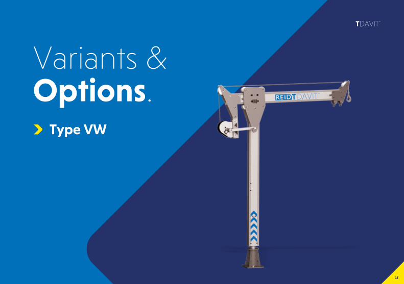
Variants & Options.
Type VW

Beam
The T DAVIT Type VW and its constituent components are described in the image below.
The use of a socket extension is optional and the socket type may vary between a Top Mount, Side Mount, Bridge Mount, Cast In or Resin Bonded, depending on application.
Ap
pro
pria
te P
PE s
houl
d b
e w
orn
:
G
love
s
P
rote
ctiv
e Fo
otw
ear
Har
d H
atAssembly Instructions
Socket (Top Mount shown - others available)
Rear Sheave
Winch
Winch Attachment Column
Shackle/Winch Plate
Shackle
Column
Cheek Plate
Front Sheave
Lifeline/Winch Line

Insert the T DAVIT into the socket as shown Place the beam between rollers and slide it in Insert and secure bolt and spacer as shown
This will act as a stopper to prevent the beam from disengaging
Place the winch and bracket in position Place winch attachment column to the beam as shown
Secure attachment with the nuts and bolts supplied
17
TDAVIT
Assembling the T DAVIT Type VW
Top Mount socket shown. If using a socket extension, install first. The use of a ladder may be required.
Assembling the Beam
Assembling the Winch
2 31
64 5

Secure assembly with the pins supplied Thread the rope over the sheaves The rope retaining pins need to be removed before fitting the rope
Reinsert pins ensuring they are secure
Please refer to the Operating manual of the winch before use
Assembly Instructions
7 98
10

19
TDAVIT
Variants & Options.
Type T

Beam
The T DAVIT Type T and its constituent components are described in the image below.
The use of a socket extension is optional and the socket type may vary between a Top Mount, Side Mount, Bridge Mount, Cast In or Resin Bonded, depending on application.
Ap
pro
pria
te P
PE s
houl
d b
e w
orn
:
G
love
s
P
rote
ctiv
e Fo
otw
ear
Har
d H
atAssembly Instructions
Socket (Top Mount shown - others available)
Column
Cheek Plate
Geared Trolley

Remove bolt and spacer at the front of the beam
Reinsert bolt and spacer ensuring they are secure Insert T Davit column into the socket
Thread beam trolley over the end of the beam Lock trolley with friction brake at approximately centre position
21
TDAVIT
Assembling the T DAVIT Type T
1
4 5
2 3

Secure the pin with retaining R-clip
Secure the pin with retaining R-clip The T Davit is now erect
Rotate the beam as illustrated
Insert rear clevis pin
Present the beam to the column and insert clevis pin to take the weight of the beam
Assembly Instructions
Assembling the Beam
7
10 11
8
9
6

Release trolley brake Use the hand chain to move the trolley along the beam
23
TDAVIT
12 13

Dimensions
Radius A
Radius B
Height of Lift A
Height of Lift B
Winch Position 1
Winch Position 2
Winch Position 3
Winch Position 4
Winch Position 5
Height of Pin Position 1
Height of Pin Position 2
A
W1
W2
W3
W4
P1
W5
P2
B
C
D
TDAVIT
DC
B
AW1
P1P2
W2
W3W4
W5
125
150
73
Type W
Position A
Position B

25
TDAVIT
Dimensions are to hook on Winched type. *Radii achieved at 75% Capacity
Height of Lift (HoL)
Column Option A B A B A B Weight (lbs) Winch Position P1 P2
3 52" 64½" 52" 67½" N/A N/A 51
W1 7½"
58" 61¾"
W2 12½"
W3 24½"
W4 29¾"
W5 34¾"
4 N/A N/A 64¾" 80" 64¾" 86" 55
W3 24½"
70¼" 74¼"W4 29¾"
W5 34¾"
Beam Option 1 2 3
BEAM LENGTH 57" 65" 80 ¾”
POSITION A B A B A B
REACH 39¼" 36½" 47¼" 43¾" 63" 58¼"
LOAD RATING (lbs) 1100 1100 820
WEIGHT (lbs) 26 29 35

Dimensions
Radius A
Radius B
Height of Lift A
Height of Lift B
Height of Pin Position 1
Height of Pin Position 2
A
P1
P2
B
C
D
TDAVIT
DC
B
A
P1P2
Type S
Position A
Position B

27
TDAVIT
Height of Lift (HoL)
Column Option A B A B A B Weight (lbs) Winch Position P1 P2
3 52" 64½" 52" 67½" N/A N/A 51
W1 7½"
58" 61¾"
W2 12½"
W3 24½"
W4 29¾"
W5 34¾"
4 N/A N/A 64¾" 80" 64¾" 86" 55
W3 24½"
70¼" 74¼"W4 29¾"
W5 34¾"
Beam Option 1 2 3
BEAM LENGTH 57" 65" 80 ¾”
POSITION A B A B A B
REACH 33¼" 30½" 41¼" 37¾" 57" 52¼"
LOAD RATING (lbs) 1100 1100 820
WEIGHT (lbs) 22 24 30
*Radii achieved at 75% Capacity

Regulations, Standards & Directives
This product complies with the following:
ATEX Directive - 2014/34/EU
Machinery Directive 2006/42/EC
PPE Regulation (EU) 2016/425
The Provision and Use of Work Equipment Regulations 1998 (S.I. 1998 No. 2306)
The Lifting Operations and Lifting Equipment Regulations 1998 (S.I. 1998 No. 2307)
In conformity with EN795:2012, AS/NZS 5532:2013 and PD CEN/TS 16415:2013
It is essential to adhere to the safety regulations of the respective country for using manual lifting equipment.
AccreditationsQuality and Safety are at the heart of the REID Lifting ethos and we are committed to maintaining the very highest standards. With this in mind, we have undertaken external accreditations to ensure we stay focused on what is important to our clients and users, and ahead of market trends and developments.
REID Lifting is continuously audited by Lloyds Register Quality Assurance (LRQA) for approval of its Integrated Management System combining quality systems management, environmental issues and the health and safety practices within the company.
ISO 9001:2015 - Quality management system which assesses an organization’s ability to consistently provide products that meet customer and applicable regulatory requirements and aims to enhance customer satisfaction.
ISO 14001:2015 - Specifies the requirements for implementing environmental management systems throughout all areas of the organization.
OHSAS 18001:2007 - Occupational health and safety management system.
LEEA Membership - REID Lifting is a full member of the Lifting Equipment Engineers Association (LEEA membership 000897). REID Lifting conforms to the main aims of the association which is to achieve the highest standards of quality and integrity in the operations of members. Entry qualifications are demanding and strictly enforced through technical audits based on the Technical Requirements for Members.
IRATA - REID Lifting is an associate member of the Industrial Rope Access Trade Association (IRATA International membership number 148). REID Lifting works in accordance with the IRATA Code of Practice and, in doing so, contributes to promote the development of safe systems.
Quality & Safety

Conformité Européenne [CE]REID Lifting’s products have been designed, tested and approved (as appropriate) by the Conformité Européenne. This certifies that REID Lifting’s products meet the demands of the European Directives and Regulations regarding Health and Safety requirements. The EC type-examination for this device has been carried out by SGS United Kingdom Ltd, 202b, Worle Parkway, Weston-super-Mare, BS22 6WA, United Kingdom (CE body no.0120) in accordance with Module B of the PPE Regulation. The EC quality assurance system for this device has been carried out by SGS Fimko Oy, Takomotie 8, FI-00380 Helsinki, Finland. (CE body no. 0598) in accordance with Module D PPE Regulation (EU) 2016/425.
TestingTesting and technical file review are integral parts of our design and manufacturing process. External verification of products is undertaken where appropriate, using government approved Notified Bodies.
All products have been thoroughly type tested. Each product is supplied with a certificate of conformance and individual record of thorough examination or test.
Language
It is essential for the safety of the user that if this product is re-sold outside of the original country of destination, the reseller shall provide instructions for use, maintenance, inspection and repair in the language of the country where it will be used.
Product IPRIntellectual property rights apply to all REID Lifting Ltd products. There are patents in place, or pending, for:
All product names are trademarks of REID Lifting Ltd:
PORTADAVIT PORTABASE
PORTAQUAD
PORTAGANTRY RAPIDE
PORTADAVIT QUANTUM TDAVIT
PORTAGANTRY
PORTAGANTRY RAPIDE
TDAVIT
PORTAGANTRY
29
TDAVIT

Product Labelling
Product labelling
The following labels must be present on the product and must be legible.
lbs
1 2
3
4
6
3
3
46
5
12
5
2
1

Date Inspected by Pass/Fail Comments
Marking
The serial labels indicate:
The product identification number
The product’s unique serial number
The goods’ capacity (WLL) of the device
The year of manufacture
The standards to which the device is approved
The ATEX rating of the product (if applicable)
CE Marking
Minimum braking load (MBL)
Periodic Examination & Repair History
Insert data from serial numbers found on product into table here:
31
TDAVIT
Product labelling
The following labels must be present on the product and must be legible.
Product Labelling

REID Lifting Inc, USA7900 International Drive, Suite 300, Bloomington, MN 55425USA
+1 952 851 5554
us.reidlifting.com
Printed using environment friendly processes and materials.
All information herein is copyright protected by REID Lifting Ltd. All company and product names are Trade Mark and Trade Name
protected and all REID Lifting Ltd. Product IPR is protected under Patents, Patents Pending and/or Design Rights.
Contact Us
TD/O
&M
/US/
V1/
02/
2020


