80
Electronic Components, Modules and Systems www.global.tdk.com · www.epcos.com TDK and EPCOS Product Survey 2017
Electronic Components,Modules and Systems
www.global.tdk.com · www.epcos.com
TDK and EPCOS Product Survey 2017
Superior Solutionsfor a Smart World.
Contents
• Transformers 4
• Power Inductors 7
• Signal Use Inductors 12
• Multilayer Inductors 14
• Signal EMC Filters 15
• Power EMC Filters, Reactors and Chokes 20
• Ferrites 23
• Noise Suppressing Sheets 26
• Important Notes 76
Magnetics 4
• Ceramic and Thin-Film RF Components 27 • LTCC Substrates for LED 29
SAW Components 27
• Piezo Actuators for Automotive 32
• Piezo Receivers, Buzzers 32
• Surge Arresters 33
• PTC Thermistors 35
• Varistors 38
• Inrush Current Limiters 40
• Multilayer Varistors, Ceramic Transient Voltage Suppressors (CTVS) 41
• NTC Thermistors 42
• Nebulizer Units 42
Piezo and Protection Devices 32
• NTC Sensors 43
• Pressure Sensors 47
• Humidity Sensors 48
• Applied Sensors 49
Sensors 43
• Multilayer Ceramic Capacitors 51
• Leaded Ceramic Capacitors 54
• Ultra-High Voltage Capacitors 54
Ceramic Capacitors 51
• Medium Power Film Capacitors 55
• DC Link, DC Filtering Film Capacitors 58
• AC Output/Input Filters 58
• AC Film Capacitors 59
• PFC Capacitors and Key Components for Power Quality Solutions 60
• Power Capacitors 63
Film Capacitors 55
• Ferrite Magnets 68 • Rare Earth Magnets 69
Magnets 68
• Bluetooth V4.1 Smart Single Mode Module 31
Micro Modules 31
• MEMS Devices for Mobile Communications and IT 30
MEMS Devices 30
Aluminum Electrolytic Capacitors 65
Electric Double Layer Capacitors 67
Wireless Charging 73

4 Please read Important notes on page 76. © TDK-EPC Corporation 2010
MagneticsTransformers
EPCOSTDK
Series EP6 shielded – SMD EHR – SMD EP7 … EP13 – SMD ER11 – SMD
Technicaldata
Features
Applications
Transformers
Output voltage (typ.):80 … 140 V
Size (l x w x h):9 x 7.6 x 7.4 mm
– High turns ratio– Low leakage inductance– High frequencies– Insensitive to external
fields– AEC-Q200 approved
Xenon lightsLED headlightsPiezo fuel injection systems
Power suppliesDC/DC converters
Power suppliesPower over Ethernet (PoE)
Power: 20 … 50 W
– High saturation currents– Low leakage inductance– High frequencies – AEC-Q200 approved
Size (l x w x h):EP7: 10 x 8.0 x 10.9 mmEP10: 12.6 x 14.4 x 13.6 mmEP13: 13.6 x 18.3 x 13.2 mm
– Low leakage inductance– Compact design– Supplementary/
reinforced insulation levels
Power: up to 1 W
Size (l x w x h):12 x 13 x 6 mm
– Low stray inductance– High power density– High operating
frequencies
Series EF12.6 … EF25 Current-sense transformers – Current-sense transformers – Power chokes –SMD EP7 / EP10 PCEM seriesB82801 CTEM series – SMD
Technicaldata
Features
Applications
Transformers
Power: up to 20 W
Size (l x w x h):15.5 x 14.5 x 12.5 … 28.5 x 28.9 x 21 mm
– Pin-to-Hole (PTH)– High creepage distance– High dielectric strength– Types with 8 mm creepage
and clearance distanceavailable
Sensed current 7… 40 A
Turns ratio: 1:20 … 1:200
– Standard designs in SMD– Three different sizes
available– Very low DC resistance,
losses and high reliability– Ruggedness and simple
implementation– Customized designs
Isense: up to 30 ARMS
Turns ratio: 1:50 up to 1:180
– AEC-Q200 approved– Basis isolation
LR: 1 … 3 µH
IR: up to 210 A
– Basic isolation– Low DC resistance– AEC-Q200 approved
Park Distance Control units (PDC)
Power supplies Compact DC/DC convertersfor midrange power
– Electric car applications(xEV)
– Switch-mode power supplies
Electric car applications(xEV)
5© TDK-EPC Corporation 2010 Please read Important notes on page 76.
MagneticsTransformers
EPCOSTDK
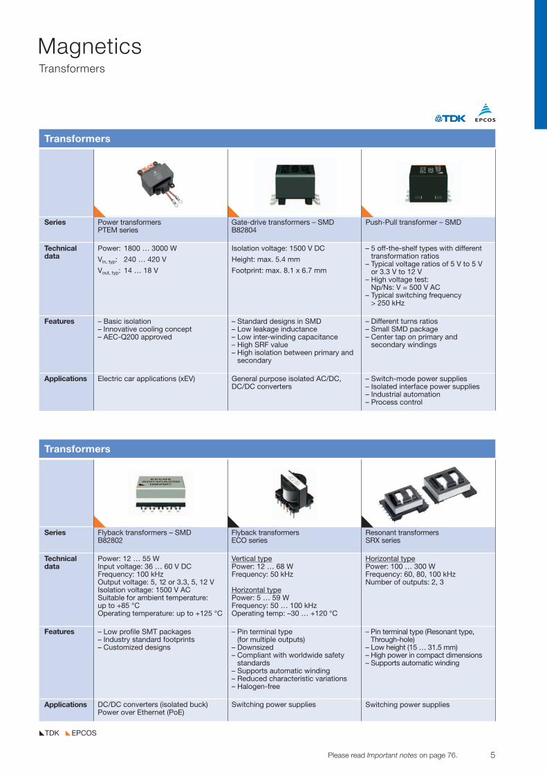
Series Power transformers Gate-drive transformers – SMD Push-Pull transformer – SMDPTEM series B82804
Technicaldata
Features
Applications
Transformers
Power: 1800 … 3000 W
Vin, typ: 240 … 420 V
Vout, typ: 14 … 18 V
– Basic isolation– Innovative cooling concept– AEC-Q200 approved
Isolation voltage: 1500 V DC
Height: max. 5.4 mm
Footprint: max. 8.1 x 6.7 mm
– Standard designs in SMD– Low leakage inductance– Low inter-winding capacitance– High SRF value– High isolation between primary and
secondary
– 5 off-the-shelf types with differenttransformation ratios
– Typical voltage ratios of 5 V to 5 V or 3.3 V to 12 V
– High voltage test: Np/Ns: V = 500 V AC
– Typical switching frequency > 250 kHz
– Different turns ratios – Small SMD package – Center tap on primary and
secondary windings
Electric car applications (xEV) General purpose isolated AC/DC,DC/DC converters
– Switch-mode power supplies – Isolated interface power supplies – Industrial automation – Process control
Series Flyback transformers – SMD Flyback transformers Resonant transformersB82802 ECO series SRX series
Technicaldata
Features
Applications
Transformers
Power: 12 … 55 W Input voltage: 36 … 60 V DC Frequency: 100 kHzOutput voltage: 5, 12 or 3.3, 5, 12 VIsolation voltage: 1500 V ACSuitable for ambient temperature:up to +85 °C Operating temperature: up to +125 °C
– Low profile SMT packages– Industry standard footprints– Customized designs
Vertical typePower: 12 … 68 WFrequency: 50 kHz
Horizontal typePower: 5 … 59 WFrequency: 50 … 100 kHzOperating temp: –30 … +120 °C
– Pin terminal type (for multiple outputs)
– Downsized– Compliant with worldwide safety
standards– Supports automatic winding– Reduced characteristic variations– Halogen-free
Horizontal typePower: 100 … 300 W Frequency: 60, 80, 100 kHz Number of outputs: 2, 3
– Pin terminal type (Resonant type, Through-hole)
– Low height (15 … 31.5 mm) – High power in compact dimensions– Supports automatic winding
DC/DC converters (isolated buck)Power over Ethernet (PoE)
Switching power supplies Switching power supplies
6 Please read Important notes on page 76. © TDK-EPC Corporation 2010
MagneticsTransformers
EPCOSTDK
Series Energy management system Gate-drive transformersCCT series VGT series – SMD
Technicaldata
Features
Applications
Transformers
Size: 261631, 272440, 323047, 354571, 406393Inner diameter: 6 … 36 mmOperating temperature: –20 … +60 °CCurrent transformation ratio: 3000:1Maximum AC current: 30 … 600 AMax. output current ±1%: 10 … 200 mASecondary winding resistance: 64 … 492 Ö
– Clamp type for easy installation on existing powerequipment
– Accommodates automatic process from wire wrappingand winding to soldering, ensuring high quality and stable supply
– Equipped with a built-in open-circuit protective device
– High flux density cores have been adopted to achieveminiaturization
– Dielectric strength voltage is 2.6 kV
Energy management systems (EMS) for buildings, factories, stores and communities (BEMS, FEMS, SEMS,CEMS)
Automotive: IPM drive of motor inverters.
Inductance: 10 mH ± 20% (100 kHz, 1V)Leakage inductance: 0.2 mH max. (100 kHz, 1V, NF, NS shorted)Withstanding voltage: NP, NF – NS: 2.6 kVRMSOperating temperature: –40 … +130 °C
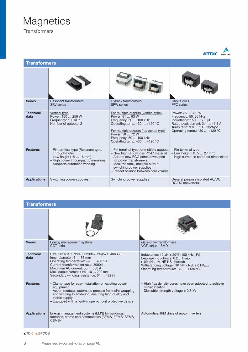
Series Resonant transformers Flyback transformers Choke coilsSRV series SRW series PFC series
Technicaldata
Features
Applications
Transformers
Vertical typePower: 160 … 250 WFrequency: 100 kHzNumber of outputs: 2
– Pin terminal type (Resonant type,Through-hole)
– Low height (15 … 16 mm)– High power in compact dimensions– Supports automatic winding
For multiple outputs (vertical type) Power: 51 … 83 WFrequency: 50 … 100 kHzOperating temp: –30 … +120 °C
For multiple outputs (horizontal type) Power: 58 … 72 WFrequency: 50 … 100 kHzOperating temp: –30 … +120 °C
– Pin terminal type for multiple outputs– New high B, low loss PC47 material– Adopts new EGG cores developed
for power transformers– Ideal for small, multiple output
switching power supplies– Perfect balance between core volume
Power: 75 … 300 W Frequency: 50, 65 kHzInductance: 150 … 600 µHRated peak current: 2.4 … 11.1 ATurns ratio: 9.0 … 10.8 Np/NpdOperating temp.: –30 … +120 °C
– Pin terminal type– Low height (15.5 … 27 mm)– High current in compact dimensions
Switching power supplies Switching power supplies General purpose isolated AC/DC,DC/DC converters
7© TDK-EPC Corporation 2010 Please read Important notes on page 76.
MagneticsTransformers, Power Inductors
EPCOSTDK
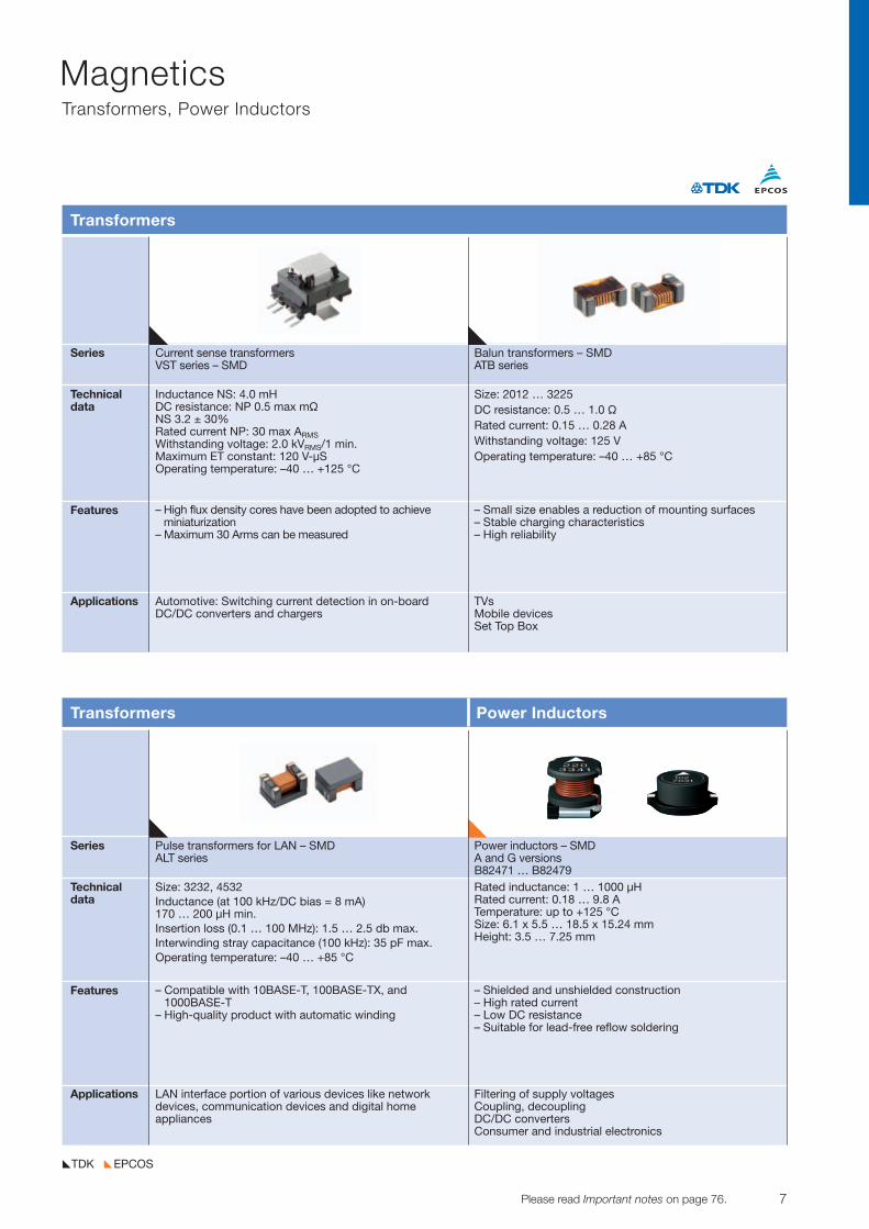
Series Current sense transformers Balun transformers – SMDVST series – SMD ATB series
Technicaldata
Features
Applications
Transformers
Inductance NS: 4.0 mHDC resistance: NP 0.5 max mÖNS 3.2 ± 30%Rated current NP: 30 max ARMSWithstanding voltage: 2.0 kVRMS/1 min.Maximum ET constant: 120 V-µSOperating temperature: –40 … +125 °C
– High flux density cores have been adopted to achieveminiaturization
– Maximum 30 Arms can be measured
– Small size enables a reduction of mounting surfaces– Stable charging characteristics– High reliability
Automotive: Switching current detection in on-boardDC/DC converters and chargers
TVsMobile devicesSet Top Box
Size: 2012 … 3225 DC resistance: 0.5 … 1.0 ÖRated current: 0.15 … 0.28 AWithstanding voltage: 125 VOperating temperature: –40 … +85 °C
Series Pulse transformers for LAN – SMD Power inductors – SMDALT series A and G versions
B82471 … B82479Technicaldata
Features
Applications
Transformers Power Inductors
Size: 3232, 4532 Inductance (at 100 kHz/DC bias = 8 mA) 170 … 200 µH min. Insertion loss (0.1 … 100 MHz): 1.5 … 2.5 db max.Interwinding stray capacitance (100 kHz): 35 pF max.Operating temperature: –40 … +85 °C
– Compatible with 10BASE-T, 100BASE-TX, and1000BASE-T
– High-quality product with automatic winding
– Shielded and unshielded construction– High rated current– Low DC resistance– Suitable for lead-free reflow soldering
LAN interface portion of various devices like network devices, communication devices and digital home appliances
Filtering of supply voltagesCoupling, decouplingDC/DC convertersConsumer and industrial electronics
Rated inductance: 1 … 1000 µHRated current: 0.18 … 9.8 ATemperature: up to +125 °CSize: 6.1 x 5.5 … 18.5 x 15.24 mmHeight: 3.5 … 7.25 mm
8 Please read Important notes on page 76. © TDK-EPC Corporation 2010
MagneticsPower Inductors
EPCOSTDK
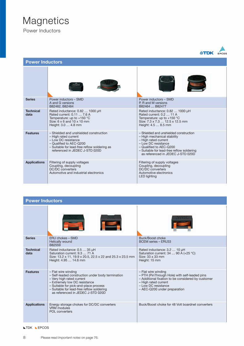
Series Power inductors – SMD Power inductors – SMDA and G versions P, R and M versionsB82462, B82464 B82464 … B82477
Technicaldata
Features
Applications
Power Inductors
Rated inductance: 0.82 … 1000 µHRated current: 0.11 … 7.6 ATemperature: up to +150 °CSize: 6 x 6 and 10 x 10 mmHeight: 3.0 … 4.8 mm
– Shielded and unshielded construction– High rated current– Low DC resistance– Qualified to AEC-Q200– Suitable for lead-free reflow soldering as
referenced in JEDEC J-STD 020D
– Shielded and unshielded construction– High mechanical stability– High rated current– Low DC resistance– Qualified to AEC-Q200– Suitable for lead-free reflow soldering
as referenced in JEDEC J-STD 020D
Filtering of supply voltagesCoupling, decouplingDC/DC convertersAutomotive and industrial electronics
Filtering of supply voltagesCoupling, decouplingDC/DC convertersAutomotive electronicsLED lighting
Rated inductance: 0.82 … 1000 µHRated current: 0.2 … 11 ATemperature: up to +150 °CSize: 7.3 x 7.3 … 12.5 x 12.5 mmHeight: 4.5 … 8.5 mm
Series ERU chokes – SMD Buck/Boost chokeHelically wound BCEM series – ERU33B82559
Technicaldata
Features
Applications
Power Inductors
Rated inductance: 0.5 … 35 µHSaturation current: 9.3 … 71 ASize: 13.2 x 11, 19.9 x 20.5, 22.5 x 22 and 25.3 x 23.5 mmHeight: 4.95 … 14.6 mm
– Flat wire winding– Self-leaded construction under body termination– Very high rated current– Extremely low DC resistance– Suitable for pick-and-place process– Suitable for lead-free reflow soldering
as referenced in JEDEC J-STD 020D
– Flat wire winding – PTH (PinThrough Hole) with self-leaded pins – Additional fixation to be considered by customer – High rated current – Low DC resistance – AEC-Q200 under preparation
Energy storage chokes for DC/DC convertersVRM modulesPOL converters
Buck/Boost choke for 48 Volt boardnet converters
Rated inductance: 3.2 … 10 µH Saturation current: 34 … 90 A (+25 °C) Size: 33 x 33 mm Height: 15 mm
9© TDK-EPC Corporation 2010 Please read Important notes on page 76.
MagneticsPower Inductors
EPCOSTDK
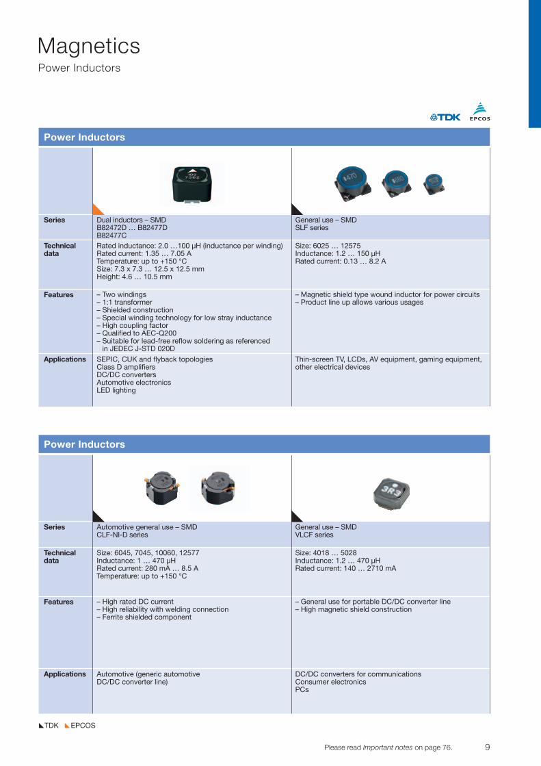
Series Dual inductors – SMD General use – SMDB82472D … B82477D SLF seriesB82477C
Technicaldata
Features
Applications
Power Inductors
Rated inductance: 2.0 …100 µH (inductance per winding)Rated current: 1.35 … 7.05 A Temperature: up to +150 °CSize: 7.3 x 7.3 … 12.5 x 12.5 mmHeight: 4.6 … 10.5 mm
– Two windings– 1:1 transformer– Shielded construction– Special winding technology for low stray inductance– High coupling factor– Qualified to AEC-Q200– Suitable for lead-free reflow soldering as referenced
in JEDEC J-STD 020D
– Magnetic shield type wound inductor for power circuits– Product line up allows various usages
SEPIC, CUK and flyback topologiesClass D amplifiersDC/DC convertersAutomotive electronicsLED lighting
Thin-screen TV, LCDs, AV equipment, gaming equipment,other electrical devices
Size: 6025 … 12575Inductance: 1.2 … 150 µHRated current: 0.13 … 8.2 A
Series Automotive general use – SMD General use – SMDCLF-NI-D series VLCF series
Technicaldata
Features
Applications
Power Inductors
Size: 6045, 7045, 10060, 12577Inductance: 1 … 470 µHRated current: 280 mA … 8.5 ATemperature: up to +150 °C
– High rated DC current– High reliability with welding connection– Ferrite shielded component
– General use for portable DC/DC converter line– High magnetic shield construction
Automotive (generic automotive DC/DC converter line)
DC/DC converters for communications Consumer electronicsPCs
Size: 4018 … 5028Inductance: 1.2 … 470 µHRated current: 140 … 2710 mA

10 Please read Important notes on page 76. © TDK-EPC Corporation 2010
MagneticsPower Inductors
EPCOSTDK
Series General use – SMD High current – SMD Thin-Film – metal compositeSPM series VLB series core technology – SMD
TFM-GHM, TFM-ALM seriesTechnicaldata
Features
Applications
Power Inductors
Size: 3012 … 12565Inductance: 0.18 … 10 µH Rated current: 1.3 … 46 ATemperature: –40 … +125 °C
– High power handling capability:Small copper lossUsing large saturation induction ofFe-based metals
– High Curie temperature of about550 °C means low inductance temperature variance
Size: 7050 … 12065Inductance: 90 … 360 nH Rated current: 14 … 68 ATemperature: –40 … +125 °C
– High output processing capacity:Minimal copper loss
– High saturation current and low DC resistance
– High operating frequency up to 2 MHz
Size 2016Inductance: 0.47 … 2.2 µH Rated current: 1.9 … 4.5 A
– Low height of 1.0 mm– Superior DC-bias characteristics– Consists of original fine copper
pattern with micro-processing technology
– Coil pattern coated with metal magnetic material
Mobile communications, consumerelectronics, servers, VRM
ServersNotebooksPCsVRMsVRDs
Generic use for DC/DC converter ofmobile communication devices
Series Thin-Film – metal composite Semi-shielded – SMD Small size, low profile, core technology – SMD VLS-EX, VLS-E series shielded – SMDTFM-ALMA VLS-CX series
Technicaldata
Features
Applications
Power Inductors
Size: 2016 … 2520Inductance: 0.47 … 2.2 µHRated current: 1.9 … 3.9 ATemperature: –40 °C … +150 °C
– Low height of 1.0 mm and 1.2 mm(2520 only)
– AEC-Q200 qualified– Excellent DC-bias characteristics– Consists of original fine copper
pattern with micro-processing technology
– Coil pattern coated with metal magnetic material
Size: 3010 … 6045Inductance: 1 … 220 µH Rated current: 0.31 … 13.5 A
– General use for portable DC/DC converter lines
Size: 2016 … 2520Inductance: 0.24 … 22 µHRated current: 0.38 … 3.08 A
– Magnetic shield type wound inductor for power circuits using ferrite magnetic material
– High magnetic shield constructionand compatible with high- densitymounting
Automotive (ECM, airbargs, headlights, electronic power steering,meters, ABS, others)
Consumer electronicsNotebooksMobile communications
Mobile communicationsConsumer electronicsLCD displaysHDDs
11© TDK-EPC Corporation 2010 Please read Important notes on page 76.
MagneticsPower Inductors
EPCOSTDK
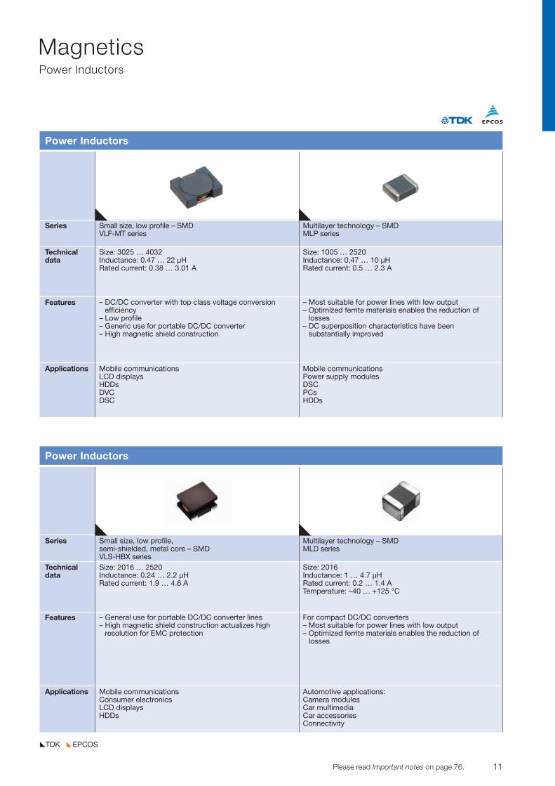
Series Small size, low profile – SMD Multilayer technology – SMDVLF-MT series MLP series
Technicaldata
Features
Applications
Power Inductors
Size: 3025 … 4032Inductance: 0.47 … 22 µH Rated current: 0.38 … 3.01 A
– DC/DC converter with top class voltage conversion efficiency
– Low profile– Generic use for portable DC/DC converter– High magnetic shield construction
– Most suitable for power lines with low output– Optimized ferrite materials enables the reduction of
losses– DC superposition characteristics have been
substantially improved
Mobile communicationsLCD displaysHDDsDVCDSC
Mobile communicationsPower supply modulesDSCPCsHDDs
Size: 1005 … 2520Inductance: 0.47 … 10 µHRated current: 0.5 … 2.3 A
Series Small size, low profile, Multilayer technology – SMDsemi-shielded, metal core – SMD MLD seriesVLS-HBX series
Technicaldata
Features
Applications
Power Inductors
Size: 2016 … 2520Inductance: 0.24 … 2.2 µH Rated current: 1.9 … 4.6 A
– General use for portable DC/DC converter lines– High magnetic shield construction actualizes high
resolution for EMC protection
For compact DC/DC converters– Most suitable for power lines with low output– Optimized ferrite materials enables the reduction of
losses
Mobile communications Consumer electronics LCD displaysHDDs
Automotive applications:Camera modulesCar multimediaCar accessoriesConnectivity
Size: 2016Inductance: 1 … 4.7 µH Rated current: 0.2 … 1.4 A Temperature: –40 … +125 °C
12 Please read Important notes on page 76. © TDK-EPC Corporation 2010
MagneticsPower Inductors, Signal Use Inductors
EPCOSTDK
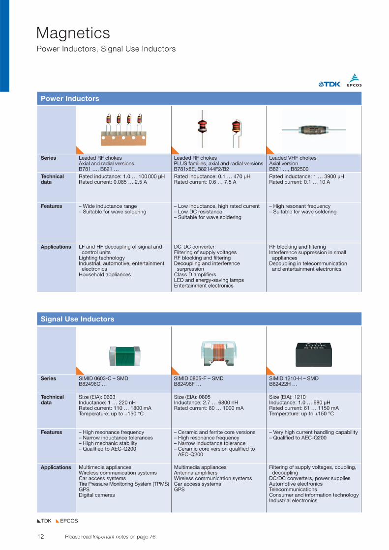
Series Leaded RF chokes Leaded RF chokes Leaded VHF chokesAxial and radial versions PLUS families, axial and radial versions Axial versionB781 …, B821 … B781x8E, B82144F2/B2 B821 …, B82500
Technicaldata
Features
Applications
Power Inductors
Rated inductance: 1.0 … 100 000 µHRated current: 0.085 … 2.5 A
– Wide inductance range– Suitable for wave soldering
Rated inductance: 0.1 … 470 µH Rated current: 0.6 … 7.5 A
– Low inductance, high rated current– Low DC resistance– Suitable for wave soldering
Rated inductance: 1 … 3900 µHRated current: 0.1 … 10 A
– High resonant frequency– Suitable for wave soldering
LF and HF decoupling of signal andcontrol units
Lighting technologyIndustrial, automotive, entertainmentelectronics
Household appliances
DC-DC converterFiltering of supply voltagesRF blocking and filteringDecoupling and interference surpression
Class D amplifiersLED and energy-saving lampsEntertainment electronics
RF blocking and filteringInterference suppression in small appliances
Decoupling in telecommunication and entertainment electronics
Series SIMID 0603-C – SMD SIMID 0805-F – SMD SIMID 1210-H – SMDB82496C … B82498F … B82422H …
Technicaldata
Features
Applications
Signal Use Inductors
Size (EIA): 0603Inductance: 1 … 220 nHRated current: 110 … 1800 mATemperature: up to +150 °C
– High resonance frequency– Narrow inductance tolerances– High mechanic stability– Qualified to AEC-Q200
Size (EIA): 0805Inductance: 2.7 … 6800 nHRated current: 80 … 1000 mA
– Ceramic and ferrite core versions– High resonance frequency– Narrow inductance tolerance– Ceramic core version qualified to
AEC-Q200
Size (EIA): 1210Inductance: 1.0 … 680 µHRated current: 61 … 1150 mATemperature: up to +150 °C
– Very high current handling capability– Qualified to AEC-Q200
Multimedia appliancesWireless communication systemsCar access systemsTire Pressure Monitoring System (TPMS) GPSDigital cameras
Multimedia appliancesAntenna amplifiersWireless communication systemsCar access systemsGPS
Filtering of supply voltages, coupling,decoupling
DC/DC converters, power suppliesAutomotive electronicsTelecommunicationsConsumer and information technologyIndustrial electronics
13© TDK-EPC Corporation 2010 Please read Important notes on page 76.
MagneticsSignal Use Inductors
EPCOSTDK
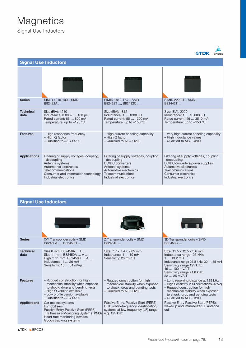
Series SIMID 1210-100 – SMD SIMID 1812-T/C – SMD SIMID 2220-T – SMDB82422A … B82432T …, B82432C … B82442T…
Technicaldata
Features
Applications
Signal Use Inductors
Size (EIA): 1210Inductance: 0.0082 … 100 µHRated current: 65 … 800 mATemperature: up to +125 °C
– High resonance frequency– High Q factor– Qualified to AEC-Q200
Size (EIA): 1812Inductance: 1 … 1000 µHRated current: 55 … 1300 mATemperature: up to +150 °C
– High current handling capability– High Q factor– Qualified to AEC-Q200
Size (EIA): 2220Inductance: 1 … 10 000 µHRated current: 46 … 3510 mATemperature: up to +150 °C
– Very high current handling capability– High inductance values– Qualified to AEC-Q200
Filtering of supply voltages, coupling,decoupling
Antenna systemsAutomotive electronicsTelecommunicationsConsumer and information technologyIndustrial electronics
Filtering of supply voltages, coupling,decoupling
DC/DC convertersAntenna systems Automotive electronics Telecommunications Industrial electronics
Filtering of supply voltages, coupling,decoupling
DC/DC converters/power suppliesAutomotive electronicsTelecommunicationsConsumer electronicsIndustrial electronics
Series X/Y Transponder coils – SMD Z Transponder coils – SMD 3D Transponder coils – SMDB82450A …, B82450H … B82451L … B82453C …
Technicaldata
Features
Applications
Signal Use Inductors
Size 8 mm: B82450A … E …Size 11 mm: B82450A … A …High Q 11 mm: B82450H … A …Inductance: 1 … 26 mHSensitivity: 10 … 51 mV/µT
– Rugged construction for high mechanical stability when exposedto shock, drop and bending tests
– High Q version available– Low profile version available– Qualified to AEC-Q200
Car access systemsImmobilisersPassive Entry Passive Start (PEPS)Tire Pressure Monitoring System (TPMS)Heart rate monitoring devicesGoods tracking systems
Size: 7.7 x 7.4 x 2.65 mmInductance: 1 … 10 mHSensitivity: 23 mV/µT
– Rugged construction for high mechanical stability when exposedto shock, drop and bending tests
– Qualified to AEC-Q200
Passive Entry, Passive Start (PEPS)RFID (radio-frequency identification)systems at low frequency (LF) rangee.g. 125 kHz
Size: 11.5 x 12.5 x 3.6 mm Inductance range 125 kHz: 1 … 13.2 mH Inductance range 21.8 kHz: 30 … 55 mHSensitivity range 125 kHz: 49 … 100 mV/µTSensitivity range 21.8 kHz: 22 … 25 mV/µT– Long receiving distance at 125 kHz– High Sensitivity in all orientations (X/Y/Z)– Rugged construction for high
mechanical stability when exposed to shock, drop and bending tests
– Qualified to AEC-Q200Passive Entry Passive Start (PEPS):wake-up and immobilizer LF antennacoil
14 Please read Important notes on page 76. © TDK-EPC Corporation 2010
MagneticsSignal Use Inductors, Multilayer Inductors
EPCOSTDK
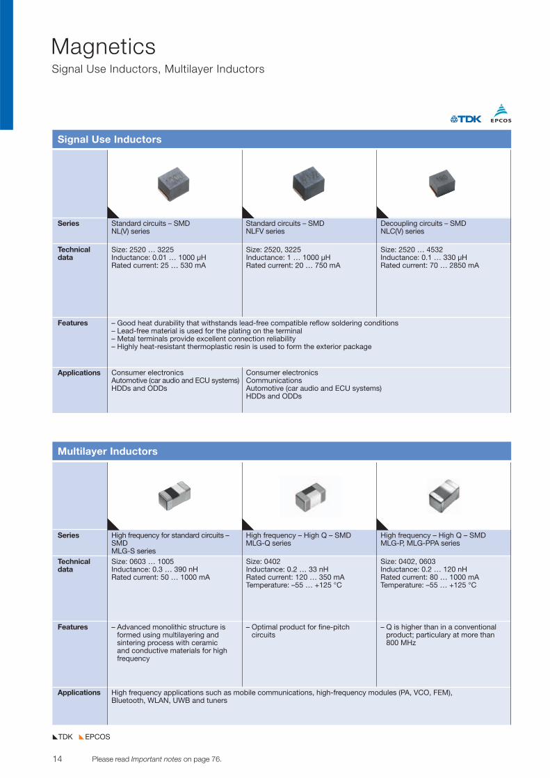
Series Standard circuits – SMD Standard circuits – SMD Decoupling circuits – SMDNL(V) series NLFV series NLC(V) series
Technicaldata
Features
Applications
Signal Use Inductors
Size: 2520 … 3225Inductance: 0.01 … 1000 µH Rated current: 25 … 530 mA
– Good heat durability that withstands lead-free compatible reflow soldering conditions– Lead-free material is used for the plating on the terminal– Metal terminals provide excellent connection reliability– Highly heat-resistant thermoplastic resin is used to form the exterior package
Size: 2520, 3225Inductance: 1 … 1000 µH Rated current: 20 … 750 mA
Size: 2520 … 4532Inductance: 0.1 … 330 µH Rated current: 70 … 2850 mA
Consumer electronicsAutomotive (car audio and ECU systems)HDDs and ODDs
Consumer electronicsCommunicationsAutomotive (car audio and ECU systems)HDDs and ODDs
Series High frequency for standard circuits – High frequency – High Q – SMD High frequency – High Q – SMD SMD MLG-Q series MLG-P, MLG-PPA seriesMLG-S series
Technicaldata
Features
Applications
Multilayer Inductors
Size: 0603 … 1005Inductance: 0.3 … 390 nH Rated current: 50 … 1000 mA
– Advanced monolithic structure isformed using multilayering and sintering process with ceramic and conductive materials for highfrequency
Size: 0402Inductance: 0.2 … 33 nH Rated current: 120 … 350 mATemperature: –55 … +125 °C
– Optimal product for fine-pitch circuits
Size: 0402, 0603Inductance: 0.2 … 120 nH Rated current: 80 … 1000 mATemperature: –55 … +125 °C
– Q is higher than in a conventionalproduct; particulary at more than800 MHz
High frequency applications such as mobile communications, high-frequency modules (PA, VCO, FEM), Bluetooth, WLAN, UWB and tuners
15© TDK-EPC Corporation 2010 Please read Important notes on page 76.
MagneticsMultilayer Inductors, Signal EMC Filters
EPCOSTDK
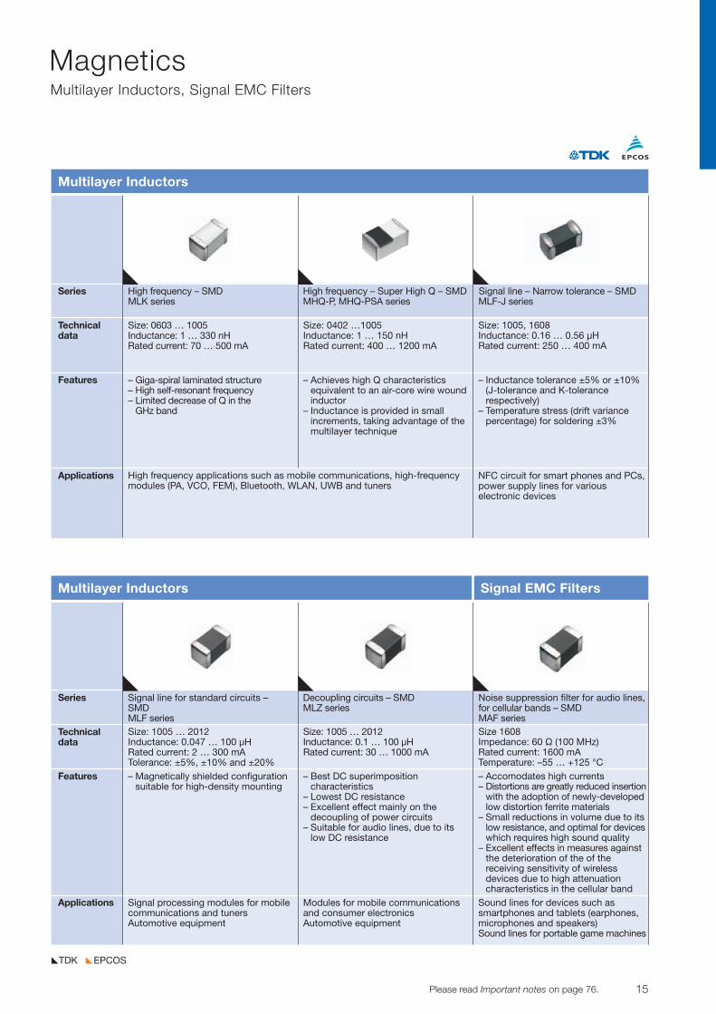
Series High frequency – SMD High frequency – Super High Q – SMD Signal line – Narrow tolerance – SMDMLK series MHQ-P, MHQ-PSA series MLF-J series
Technicaldata
Features
Applications
Multilayer Inductors
Size: 0603 … 1005Inductance: 1 … 330 nHRated current: 70 … 500 mA
– Giga-spiral laminated structure– High self-resonant frequency – Limited decrease of Q in the
GHz band
Size: 0402 …1005Inductance: 1 … 150 nH Rated current: 400 … 1200 mA
– Achieves high Q characteristicsequivalent to an air-core wire woundinductor
– Inductance is provided in small increments, taking advantage of themultilayer technique
Size: 1005, 1608Inductance: 0.16 … 0.56 µHRated current: 250 … 400 mA
– Inductance tolerance ±5% or ±10%(J-tolerance and K-tolerance respectively)
– Temperature stress (drift variancepercentage) for soldering ±3%
High frequency applications such as mobile communications, high-frequency modules (PA, VCO, FEM), Bluetooth, WLAN, UWB and tuners
NFC circuit for smart phones and PCs,power supply lines for various electronic devices
Series Signal line for standard circuits – Decoupling circuits – SMD Noise suppression filter for audio lines, SMD MLZ series for cellular bands – SMDMLF series MAF series
Technicaldata
Features
Applications
Multilayer Inductors Signal EMC Filters
Size: 1005 … 2012Inductance: 0.047 … 100 µHRated current: 2 … 300 mATolerance: ±5%, ±10% and ±20%– Magnetically shielded configuration
suitable for high-density mounting
Size: 1005 … 2012Inductance: 0.1 … 100 µH Rated current: 30 … 1000 mA
– Best DC superimposition characteristics
– Lowest DC resistance– Excellent effect mainly on the
decoupling of power circuits– Suitable for audio lines, due to its
low DC resistance
Size 1608Impedance: 60 Ö (100 MHz)Rated current: 1600 mATemperature: –55 … +125 °C– Accomodates high currents– Distortions are greatly reduced insertion
with the adoption of newly-developedlow distortion ferrite materials
– Small reductions in volume due to itslow resistance, and optimal for deviceswhich requires high sound quality
– Excellent effects in measures againstthe deterioration of the of the receiving sensitivity of wireless devices due to high attenuation characteristics in the cellular band
Signal processing modules for mobilecommunications and tunersAutomotive equipment
Modules for mobile communicationsand consumer electronicsAutomotive equipment
Sound lines for devices such as smartphones and tablets (earphones,microphones and speakers)Sound lines for portable game machines
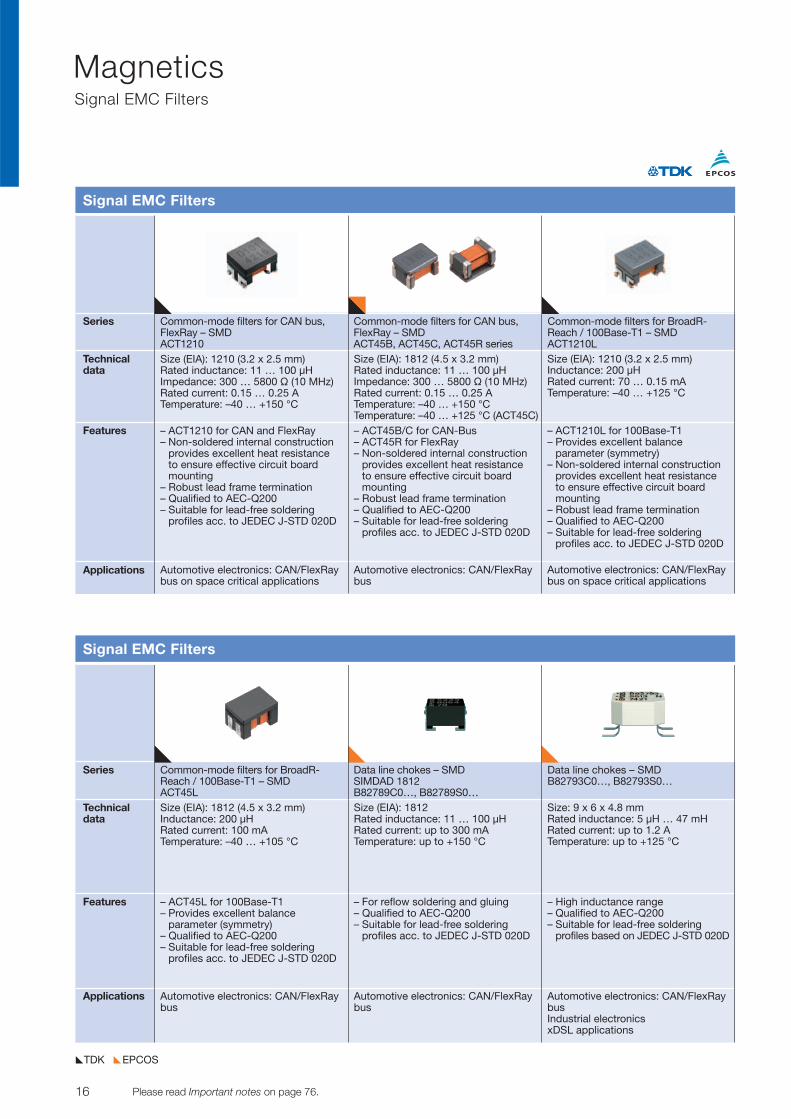
Series Common-mode filters for CAN bus, Common-mode filters for CAN bus, Common-mode filters for BroadR-FlexRay – SMD FlexRay – SMD Reach / 100Base-T1 – SMDACT1210 ACT45B, ACT45C, ACT45R series ACT1210L
Technicaldata
Features
Applications
Signal EMC Filters
Size (EIA): 1210 (3.2 x 2.5 mm) Rated inductance: 11 … 100 µH Impedance: 300 … 5800 V (10 MHz) Rated current: 0.15 … 0.25 A Temperature: –40 … +150 °C
– ACT1210 for CAN and FlexRay– Non-soldered internal construction
provides excellent heat resistance to ensure effective circuit boardmounting
– Robust lead frame termination– Qualified to AEC-Q200– Suitable for lead-free soldering
profiles acc. to JEDEC J-STD 020D
Size (EIA): 1812 (4.5 x 3.2 mm) Rated inductance: 11 … 100 µH Impedance: 300 … 5800 V (10 MHz) Rated current: 0.15 … 0.25 A Temperature: –40 … +150 °CTemperature: –40 … +125 °C (ACT45C)– ACT45B/C for CAN-Bus– ACT45R for FlexRay– Non-soldered internal construction
provides excellent heat resistance to ensure effective circuit boardmounting
– Robust lead frame termination– Qualified to AEC-Q200– Suitable for lead-free soldering
profiles acc. to JEDEC J-STD 020D
Size (EIA): 1210 (3.2 x 2.5 mm) Inductance: 200 µH Rated current: 70 … 0.15 mA Temperature: –40 … +125 °C
– ACT1210L for 100Base-T1– Provides excellent balance
parameter (symmetry)– Non-soldered internal construction
provides excellent heat resistance to ensure effective circuit boardmounting
– Robust lead frame termination– Qualified to AEC-Q200– Suitable for lead-free soldering
profiles acc. to JEDEC J-STD 020D
Automotive electronics: CAN/FlexRaybus on space critical applications
Automotive electronics: CAN/FlexRaybus
Automotive electronics: CAN/FlexRaybus on space critical applications
Series Common-mode filters for BroadR- Data line chokes – SMD Data line chokes – SMDReach / 100Base-T1 – SMD SIMDAD 1812 B82793C0…, B82793S0…ACT45L B82789C0…, B82789S0…
Technicaldata
Features
Applications
Signal EMC Filters
Size (EIA): 1812 (4.5 x 3.2 mm) Inductance: 200 µH Rated current: 100 mA Temperature: –40 … +105 °C
– ACT45L for 100Base-T1– Provides excellent balance
parameter (symmetry)– Qualified to AEC-Q200– Suitable for lead-free soldering
profiles acc. to JEDEC J-STD 020D
Size (EIA): 1812Rated inductance: 11 … 100 µHRated current: up to 300 mATemperature: up to +150 °C
– For reflow soldering and gluing– Qualified to AEC-Q200– Suitable for lead-free soldering
profiles acc. to JEDEC J-STD 020D
Size: 9 x 6 x 4.8 mmRated inductance: 5 µH … 47 mHRated current: up to 1.2 ATemperature: up to +125 °C
– High inductance range– Qualified to AEC-Q200– Suitable for lead-free soldering
profiles based on JEDEC J-STD 020D
Automotive electronics: CAN/FlexRaybus
Automotive electronics: CAN/FlexRaybus
Automotive electronics: CAN/FlexRaybusIndustrial electronicsxDSL applications
16 Please read Important notes on page 76. © TDK-EPC Corporation 2010
MagneticsSignal EMC Filters
EPCOSTDK
17© TDK-EPC Corporation 2010 Please read Important notes on page 76.
MagneticsSignal EMC Filters
EPCOSTDK
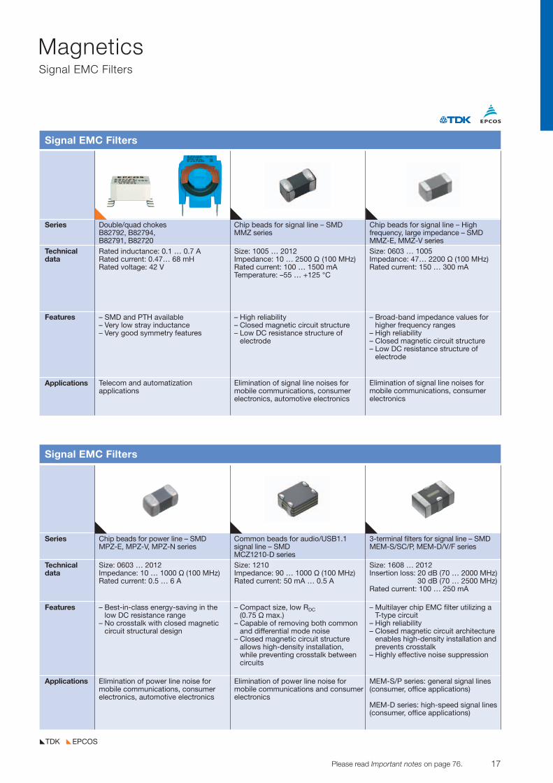
Series Double/quad chokes Chip beads for signal line – SMD Chip beads for signal line – HighB82792, B82794, MMZ series frequency, large impedance – SMDB82791, B82720 MMZ-E, MMZ-V series
Technicaldata
Features
Applications
Signal EMC Filters
Rated inductance: 0.1 … 0.7 ARated current: 0.47… 68 mHRated voltage: 42 V
– SMD and PTH available– Very low stray inductance– Very good symmetry features
Size: 1005 … 2012Impedance: 10 … 2500 V (100 MHz)Rated current: 100 … 1500 mATemperature: –55 … +125 °C
– High reliability– Closed magnetic circuit structure– Low DC resistance structure of
electrode
Size: 0603 … 1005Impedance: 47… 2200 V (100 MHz) Rated current: 150 … 300 mA
– Broad-band impedance values forhigher frequency ranges
– High reliability– Closed magnetic circuit structure– Low DC resistance structure of
electrode
Telecom and automatization applications
Elimination of signal line noises for mobile communications, consumerelectronics, automotive electronics
Elimination of signal line noises for mobile communications, consumerelectronics
Series Chip beads for power line – SMD Common beads for audio/USB1.1 3-terminal filters for signal line – SMDMPZ-E, MPZ-V, MPZ-N series signal line – SMD MEM-S/SC/P, MEM-D/V/F series
MCZ1210-D seriesTechnicaldata
Features
Applications
Signal EMC Filters
Size: 0603 … 2012Impedance: 10 … 1000 V (100 MHz)Rated current: 0.5 … 6 A
– Best-in-class energy-saving in thelow DC resistance range
– No crosstalk with closed magneticcircuit structural design
Size: 1210Impedance: 90 … 1000 V (100 MHz)Rated current: 50 mA … 0.5 A
– Compact size, low RDC(0.75 V max.)
– Capable of removing both commonand differential mode noise
– Closed magnetic circuit structure allows high-density installation, while preventing crosstalk betweencircuits
Size: 1608 … 2012Insertion loss: 20 dB (70 … 2000 MHz)
30 dB (70 … 2500 MHz) Rated current: 100 … 250 mA
– Multilayer chip EMC filter utilizing aT-type circuit
– High reliability– Closed magnetic circuit architecture
enables high-density installation andprevents crosstalk
– Highly effective noise suppression
Elimination of power line noise for mobile communications, consumerelectronics, automotive electronics
Elimination of power line noise for mobile communications and consumerelectronics
MEM-S/P series: general signal lines(consumer, office applications)
MEM-D series: high-speed signal lines(consumer, office applications)
18 Please read Important notes on page 76. © TDK-EPC Corporation 2010
MagneticsSignal EMC Filters
EPCOSTDK
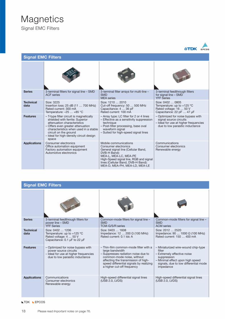
Series 3-terminal filters for signal line – SMD 3-terminal filter arrays for multi-line – 3-terminal feedthrough filtersACF series SMD for signal line – SMD
MEA series YFF SeriesTechnicaldata
Features
Applications
Signal EMC Filters
Size: 3225Insertion loss: 25 dB (11 … 700 MHz)Rated current: 300 mATemperature: –25 … +85 °C– T-type filter circuit is magnetically
shielded with ferrite: Superior attenuation characteristics
– Offers even greater attenuation characteristics when used in a stablecircuit on the ground
– Ideal for high-density circuit designspace
Size: 1210 … 2010Cut-off frequency: 50 … 500 MHzCapacitance: 4 … 36 pFRated current: 100 mA– Array type: LC filter for 2 or 4 lines– Effective as a sensitivity suppression
technique– Post-filter processing, base oval
waveform signal– Suited for high-speed signal lines
Size: 0402 … 0805Temperature: up to +125 ºC Rated voltage: 16 … 50 V Capacitance: 22 pF … 47 µF– Optimized for noise bypass with
signal source circuits– Ideal for use at higher frequencies
due to low parasitic inductance
Consumer electronicsOffice automation equipment Factory automation equipmentAutomotive electronics
Mobile communicationsConsumer electronicsGeneral signal line (Cellular Band,DVB-H Band): MEA-L, MEA-LC, MEA-PEHigh-Speed signal line, RGB and signallines (Cellular Band, DVB-H Band): MEA-D, MEA-PH, MEA-LD, MEA-LE
Communications Consumer electronics Renewable energy
Series 3-terminal feedthrough filters for Common-mode filters for signal line – Common-mode filters for signal line –power line – SMD SMD SMDYFF Series TCM-G/S/R series ACM series
Technicaldata
Features
Applications
Signal EMC Filters
Size: 0402 … 1206Temperature: up to +125 ºC Rated voltage: 4 … 50 V Capacitance: 0.1 µF to 22 µF
– Optimized for noise bypass withpower source circuits
– Ideal for use at higher frequenciesdue to low parasitic inductance
Size: 0403 … 1608Impedance: 12 … 200 V (100 MHz)Rated current: 0.1 Idc A
– Thin-film common-mode filter with alarge bandwidth
– Suppresses radiation noise due tocommon-mode noise, without affecting the transmission of high-speed differential signals by realizinga higher cut-off frequency
Size: 2012 … 2520Impedance: 90 … 1000 V (100 MHz)Rated current: 150 … 400 mA
– Miniaturized wire-wound chip-typefilter
– Extremely effective noise suppression
– Minimal effect upon high speed signals, due to low differential modeimpedance
Communications Consumer electronics Renewable energy
High-speed differential signal lines (USB 2.0, LVDS)
High-speed differential signal lines (USB 2.0, LVDS)
19© TDK-EPC Corporation 2010 Please read Important notes on page 76.
MagneticsSignal EMC Filters
EPCOSTDK
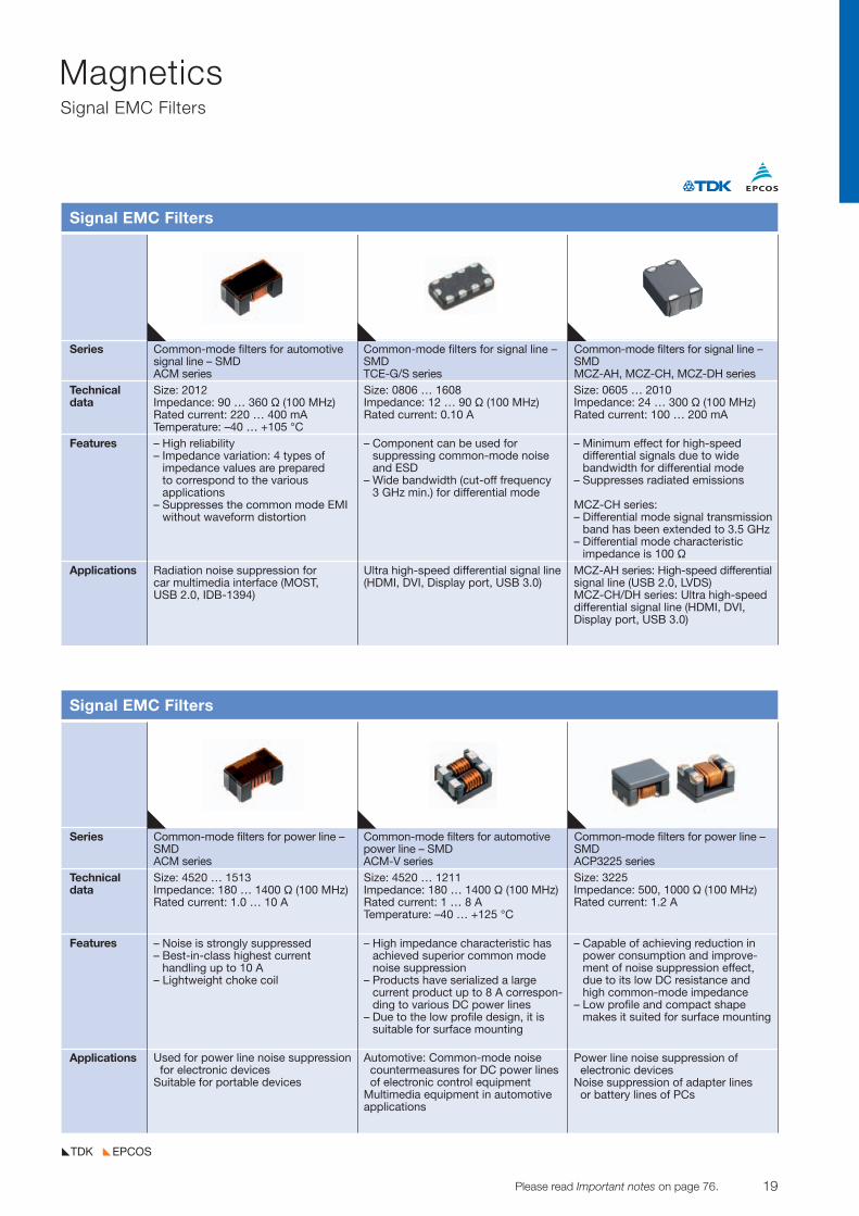
Series Common-mode filters for automotive Common-mode filters for signal line – Common-mode filters for signal line –signal line – SMD SMD SMDACM series TCE-G/S series MCZ-AH, MCZ-CH, MCZ-DH series
Technicaldata
Features
Applications
Signal EMC Filters
Size: 2012Impedance: 90 … 360 V (100 MHz)Rated current: 220 … 400 mATemperature: –40 … +105 °C– High reliability– Impedance variation: 4 types of
impedance values are prepared to correspond to the various applications
– Suppresses the common mode EMIwithout waveform distortion
Size: 0806 … 1608Impedance: 12 … 90 V (100 MHz)Rated current: 0.10 A
– Component can be used for suppressing common-mode noiseand ESD
– Wide bandwidth (cut-off frequency3 GHz min.) for differential mode
Size: 0605 … 2010Impedance: 24 … 300 V (100 MHz)Rated current: 100 … 200 mA
– Minimum effect for high-speed differential signals due to wide bandwidth for differential mode
– Suppresses radiated emissions
MCZ-CH series:– Differential mode signal transmission
band has been extended to 3.5 GHz– Differential mode characteristic
impedance is 100 V
Radiation noise suppression for car multimedia interface (MOST, USB 2.0, IDB-1394)
Ultra high-speed differential signal line(HDMI, DVI, Display port, USB 3.0)
MCZ-AH series: High-speed differentialsignal line (USB 2.0, LVDS)MCZ-CH/DH series: Ultra high-speed differential signal line (HDMI, DVI,Display port, USB 3.0)
Series Common-mode filters for power line – Common-mode filters for automotive Common-mode filters for power line –SMD power line – SMD SMDACM series ACM-V series ACP3225 series
Technicaldata
Features
Applications
Signal EMC Filters
Size: 4520 … 1513Impedance: 180 … 1400 V (100 MHz)Rated current: 1.0 … 10 A
– Noise is strongly suppressed– Best-in-class highest current
handling up to 10 A– Lightweight choke coil
Size: 4520 … 1211Impedance: 180 … 1400 V (100 MHz) Rated current: 1 … 8 A Temperature: –40 … +125 °C
– High impedance characteristic hasachieved superior common modenoise suppression
– Products have serialized a large current product up to 8 A correspon-ding to various DC power lines
– Due to the low profile design, it issuitable for surface mounting
Size: 3225Impedance: 500, 1000 V (100 MHz) Rated current: 1.2 A
– Capable of achieving reduction inpower consumption and improve-ment of noise suppression effect,due to its low DC resistance andhigh common-mode impedance
– Low profile and compact shapemakes it suited for surface mounting
Used for power line noise suppressionfor electronic devices
Suitable for portable devices
Automotive: Common-mode noise countermeasures for DC power lines of electronic control equipment
Multimedia equipment in automotiveapplications
Power line noise suppression of electronic devices
Noise suppression of adapter lines or battery lines of PCs
20 Please read Important notes on page 76. © TDK-EPC Corporation 2010
MagneticsSignal EMC Filters,Power EMC Filters, Reactors and Chokes
EPCOSTDK
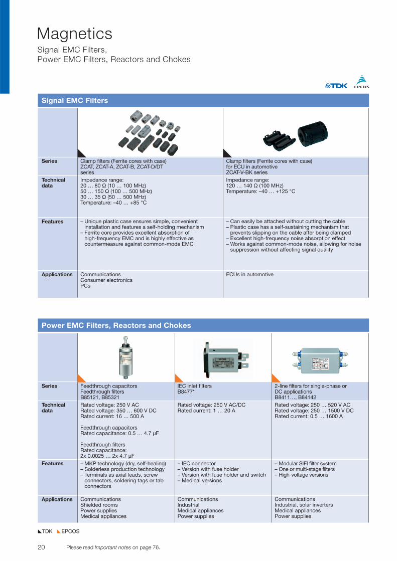
Series Clamp filters (Ferrite cores with case) Clamp filters (Ferrite cores with case)ZCAT, ZCAT-A, ZCAT-B, ZCAT-D/DT for ECU in automotiveseries ZCAT-V-BK series
Technicaldata
Features
Applications
Signal EMC Filters
Impedance range: 20 … 80 V (10 … 100 MHz)50 … 150 V (100 … 500 MHz)30 … 35 V (50 … 500 MHz)Temperature: –40 … +85 °C
– Unique plastic case ensures simple, convenient installation and features a self-holding mechanism
– Ferrite core provides excellent absorption of high-frequency EMC and is highly effective as countermeasure against common-mode EMC
– Can easily be attached without cutting the cable– Plastic case has a self-sustaining mechanism that
prevents slipping on the cable after being clamped– Excellent high-frequency noise absorption effect– Works against common-mode noise, allowing for noise
suppression without affecting signal quality
CommunicationsConsumer electronicsPCs
ECUs in automotive
Impedance range: 120 … 140 V (100 MHz)Temperature: –40 … +125 °C
Series Feedthrough capacitors IEC inlet filters 2-line filters for single-phase orFeedthrough filters B8477* DC applicationsB85121, B85321 B8411…, B84142
Technicaldata
Features
Applications
Power EMC Filters, Reactors and Chokes
Rated voltage: 250 V ACRated voltage: 350 … 600 V DCRated current: 16 … 500 A
Feedthrough capacitorsRated capacitance: 0.5 … 4.7 µF
Feedthrough filtersRated capacitance: 2x 0.0025 … 2x 4.7 µF– MKP technology (dry, self-healing)– Solderless production technology– Terminals as axial leads, screw
connectors, soldering tags or tabconnectors
Rated voltage: 250 V AC/DCRated current: 1 … 20 A
– IEC connector– Version with fuse holder– Version with fuse holder and switch– Medical versions
Rated voltage: 250 … 520 V ACRated voltage: 250 … 1500 V DCRated current: 0.5 … 1600 A
– Modular SIFI filter system– One or multi-stage filters– High-voltage versions
CommunicationsShielded roomsPower suppliesMedical appliances
Communications IndustrialMedical appliances Power supplies
CommunicationsIndustrial, solar invertersMedical appliancesPower supplies
21© TDK-EPC Corporation 2010 Please read Important notes on page 76.
MagneticsPower EMC Filters, Reactors and Chokes
EPCOSTDK
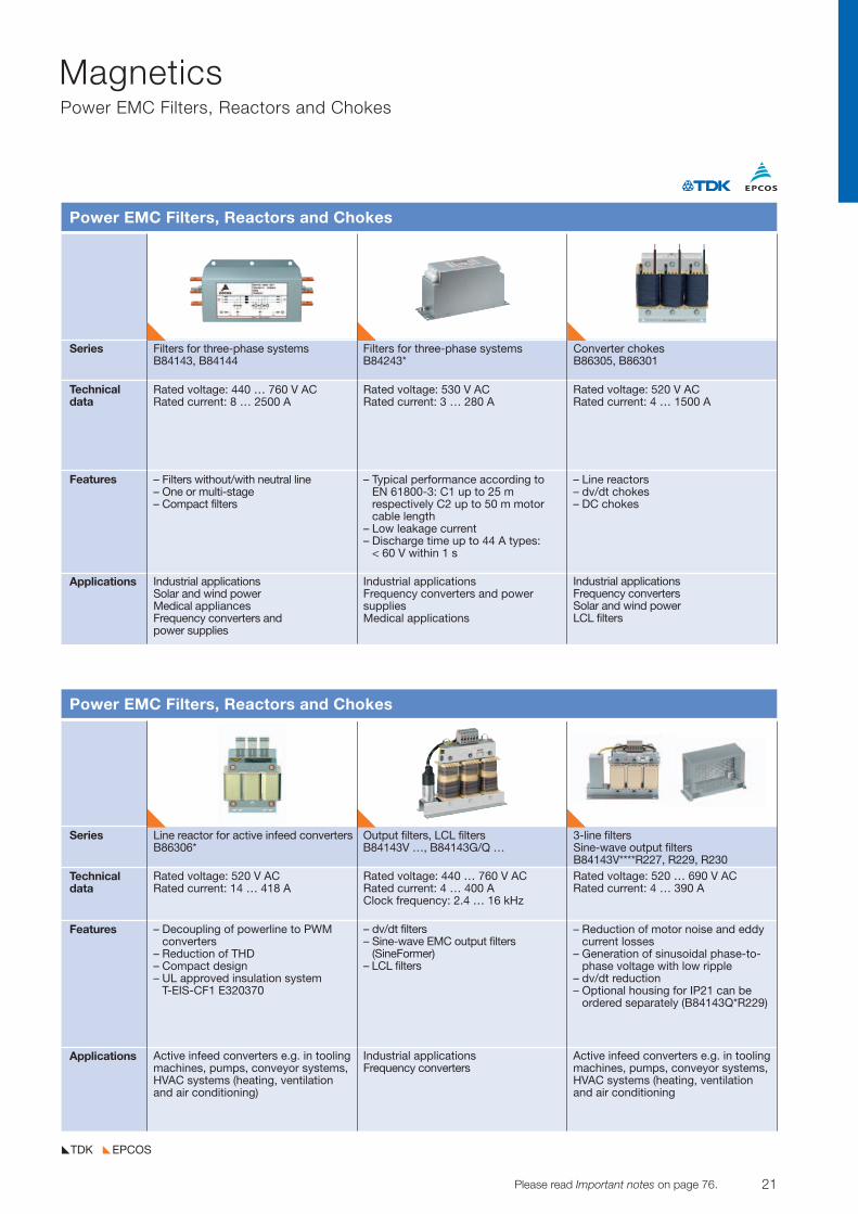
Series Filters for three-phase systems Filters for three-phase systems Converter chokesB84143, B84144 B84243* B86305, B86301
Technicaldata
Features
Applications
Power EMC Filters, Reactors and Chokes
Rated voltage: 440 … 760 V ACRated current: 8 … 2500 A
– Filters without/with neutral line– One or multi-stage– Compact filters
Rated voltage: 530 V ACRated current: 3 … 280 A
– Typical performance according to EN 61800-3: C1 up to 25 m respectively C2 up to 50 m motor cable length
– Low leakage current– Discharge time up to 44 A types:
< 60 V within 1 s
Rated voltage: 520 V ACRated current: 4 … 1500 A
– Line reactors– dv/dt chokes– DC chokes
Industrial applicationsSolar and wind powerMedical appliancesFrequency converters and power supplies
Industrial applicationsFrequency converters and power suppliesMedical applications
Industrial applicationsFrequency convertersSolar and wind powerLCL filters
Series Line reactor for active infeed converters Output filters, LCL filters 3-line filtersB86306* B84143V …, B84143G/Q … Sine-wave output filters
B84143V****R227, R229, R230Technicaldata
Features
Applications
Power EMC Filters, Reactors and Chokes
Rated voltage: 520 V ACRated current: 14 … 418 A
– Decoupling of powerline to PWMconverters
– Reduction of THD– Compact design– UL approved insulation system
T-EIS-CF1 E320370
Rated voltage: 440 … 760 V ACRated current: 4 … 400 AClock frequency: 2.4 … 16 kHz
– dv/dt filters– Sine-wave EMC output filters
(SineFormer)– LCL filters
Rated voltage: 520 … 690 V ACRated current: 4 … 390 A
– Reduction of motor noise and eddycurrent losses
– Generation of sinusoidal phase-to-phase voltage with low ripple
– dv/dt reduction– Optional housing for IP21 can be
ordered separately (B84143Q*R229)
Active infeed converters e.g. in toolingmachines, pumps, conveyor systems,HVAC systems (heating, ventilation and air conditioning)
Industrial applicationsFrequency converters
Active infeed converters e.g. in toolingmachines, pumps, conveyor systems,HVAC systems (heating, ventilation and air conditioning
22 Please read Important notes on page 76. © TDK-EPC Corporation 2010
MagneticsPower EMC Filters, Reactors and Chokes
EPCOSTDK
Series Ring core chokes Ring core chokes D core chokes(current compensated) (current compensated) (current compensated)B82725S … B82726E/S …, B82727E … B82724J*U* B82731 … B82734
Technicaldata
Features
Applications
Power EMC Filters, Reactors and Chokes
Rated current: 5.4 … 56 ARated inductance: 0.19 … 7.8 mH Rated voltage: 250 … 300 V AC
300 … 1000 V DC (DC link)
– High resonance frequency – Approx. 1% stray inductance for
symmetrical interference suppression
– On baseplate, winding wire servesas solder terminal
Rated current: 4.3 … 10 ARated inductance: 0.5 … 6.8 mH Rated voltage: 250 V
– High resonance frequency owing tospecial winding technique
– Approx. 1% stray inductance forsymmetrical interference suppression
– Plastic case with terminals– High rated temperatures
Rated inductance: 3.3 … 100 mHRated current: 0.35 … 4.6 ARated voltage: 250 V
– High resonance frequency due to 2-section winding
– Approx. 1% stray inductance for symmetrical interference suppression
– Low leakage due to closed coreshape
– High pulse strength– Low whirring noise– Low-height horizontal versions
Power supplies of high power applications, such as solar inverters, drives, household appliances
Inverter applications in home appliance, e.g. washing machine, dryer
Power suppliesBallasts
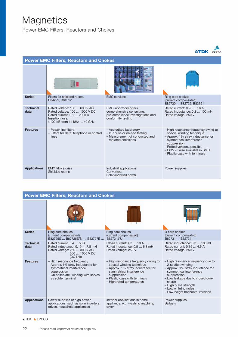
Series Filters for shielded rooms EMC services Ring core chokes B84299, B84312 (current compensated)
B82720 … B82725, B82791Technicaldata
Features
Applications
Power EMC Filters, Reactors and Chokes
Rated voltage: 100 … 690 V ACRated voltage: 100 … 1000 V DCRated current: 0.1 … 2000 AInsertion loss: >100 dB from 14 kHz … 40 GHz
– Power line filters– Filters for data, telephone or control
lines
EMC laboratory offerscomprehensive consulting,pre-compliance investigations andconformity testing
– Accredited laboratory– In-house or on-site testing– Measurement of conducted and
radiated emissions
Rated current: 0.25 … 16 ARated inductance: 0.2 … 100 mHRated voltage: 250 V
– High resonance frequency owing tospecial winding technique
– Approx. 1% stray inductance for symmetrical interference suppression
– Potted versions possible– B82720 also available in SMD– Plastic case with terminals
EMC laboratoriesShielded rooms
Industrial applicationsConvertersSolar and wind power
Power supplies
23© TDK-EPC Corporation 2010 Please read Important notes on page 76.
MagneticsPower EMC Filters, Reactors and Chokes, Ferrites
EPCOSTDK
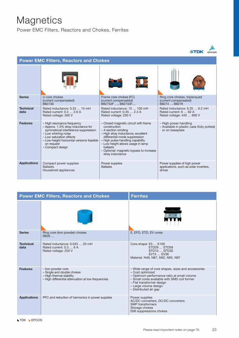
Series U core chokes Frame core chokes (FC) Ring core chokes, triple/quad(current compensated) (current compensated) (current compensated) B82730 B82732F …, B82733F… B8274 … B8276
Technicaldata
Features
Applications
Power EMC Filters, Reactors and Chokes
Rated inductance: 0.33 … 15 mHRated current: 0.4 … 2.6 ARated voltage: 300 V
– High resonance frequency– Approx. 1.3% stray inductance for
symmetrical interference suppression– Low whirring noise– Low saturation effects– Low-height horizontal versions feasible
on request– Compact design
Rated inductance: 10 … 100 mHRated current: 0.45 … 2.3 ARated voltage: 250 V
– Closed magnetic circuit with frame construction
– 4-section winding– High stray inductance, excellent
differential mode suppression– High pulse-handling capability– Low height allows usage in lamp
ballasts– Optional: magnetic bypass to increase
stray inductance
Rated inductance: 0.35 … 6.2 mHRated current: 6 … 62 ARated voltage: 440 … 690 V
– High power handling– Available in plastic case (fully potted)
or on baseplate
Compact power suppliesBallastsHousehold appliances
Power suppliesBallasts
Power supplies of high power applications, such as solar inverters,drives
Series Ring core (iron powder) chokes E, EFD, ETD, EV coresB826 …
Technicaldata
Features
Applications
Power EMC Filters, Reactors and Chokes Ferrites
Rated inductance: 0.033 … 20 mHRated current: 0.3 … 6 ARated voltage: 250 V
– Iron powder core– Single and double chokes– High thermal stability – High differential attenuation at low frequencies
– Wide range of core shapes, sizes and accessories– Cost optimized– Optimum performance ratio at small volume– Small cores available with SMD coil former– Flat transformer design– Large volume design– Distributed air gap
PFC and reduction of harmonics in power supplies Power suppliesAC/DC converters, DC/DC convertersSMP transformersStorage chokesEMI suppressions chokes
Core shape: E5 … E100ETD29 … ETD59EFD10 … EFD30EV15 … EV36
Material: N49, N87, N92, N95, N97
24 Please read Important notes on page 76. © TDK-EPC Corporation 2010
MagneticsFerrites
EPCOSTDK
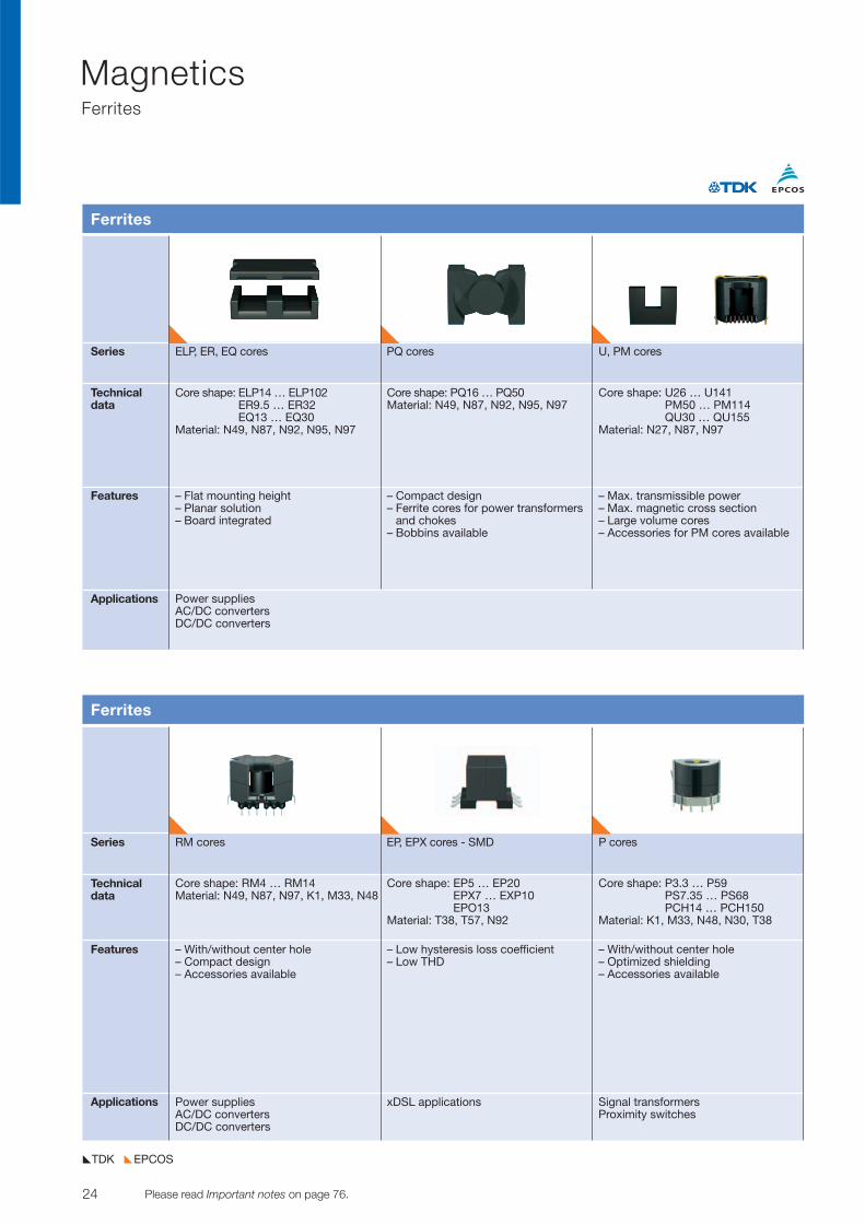
Series RM cores EP, EPX cores - SMD P cores
Technicaldata
Features
Applications
Ferrites
Core shape: RM4 … RM14Material: N49, N87, N97, K1, M33, N48
– With/without center hole– Compact design– Accessories available
Core shape: EP5 … EP20EPX7 … EXP10EPO13
Material: T38, T57, N92
– Low hysteresis loss coefficient– Low THD
Core shape: P3.3 … P59PS7.35 … PS68PCH14 … PCH150
Material: K1, M33, N48, N30, T38
– With/without center hole– Optimized shielding– Accessories available
Power suppliesAC/DC convertersDC/DC converters
xDSL applications Signal transformersProximity switches
Series ELP, ER, EQ cores PQ cores U, PM cores
Technicaldata
Features
Applications
Ferrites
Core shape: ELP14 … ELP102ER9.5 … ER32EQ13 … EQ30
Material: N49, N87, N92, N95, N97
– Flat mounting height– Planar solution– Board integrated
Core shape: PQ16 … PQ50Material: N49, N87, N92, N95, N97
– Compact design– Ferrite cores for power transformers
and chokes– Bobbins available
Core shape: U26 … U141PM50 … PM114QU30 … QU155
Material: N27, N87, N97
– Max. transmissible power– Max. magnetic cross section– Large volume cores– Accessories for PM cores available
Power suppliesAC/DC convertersDC/DC converters
25© TDK-EPC Corporation 2010 Please read Important notes on page 76.
MagneticsFerrites
EPCOSTDK
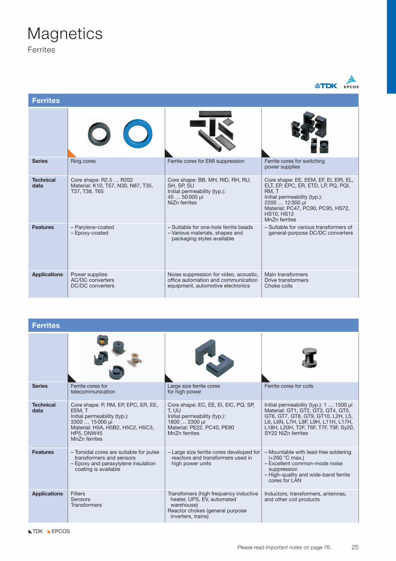
Series Ring cores Ferrite cores for EMI suppression Ferrite cores for switchingpower supplies
Technicaldata
Features
Applications
Ferrites
Core shape: R2.5 … R202Material: K10, T57, N30, N87, T35,T37, T38, T65
– Parylene-coated– Epoxy-coated
Core shape: BB, MH, RID, RH, RU, SH, SP, SU Initial permeability (typ.): 45 … 50 000 µiNiZn ferrites
– Suitable for one-hole ferrite beads– Various materials, shapes and
packaging styles available
Core shape: EE, EEM, EF, EI, EIR, EL,ELT, EP, EPC, ER, ETD, LP, PQ, PQI,RM, TInitial permeability (typ.):2200 … 12 000 µiMaterial: PC47, PC90, PC95, HS72,HS10, HS12MnZn ferrites– Suitable for various transformers of
general-purpose DC/DC converters
Noise suppression for video, acoustic,office automation and communicationequipment, automotive electronics
Power suppliesAC/DC convertersDC/DC converters
Main transformersDrive transformersChoke coils
Series Ferrite cores for Large size ferrite cores Ferrite cores for coilstelecommunication for high power
Technicaldata
Features
Applications
Ferrites
Core shape: P, RM, EP, EPC, ER, EE,EEM, TInitial permeability (typ.):3300 … 15 000 µiMaterial: H5A, H5B2, H5C2, H5C3,HP5, DNW45 MnZn ferrites
– Toroidal cores are suitable for pulsetransformers and sensors
– Epoxy and paraxylylene insulationcoating is available
Core shape: EC, EE, EI, EIC, PQ, SP, T, UUInitial permeability (typ.): 1800 … 2300 µiMaterial: PE22, PC40, PE90MnZn ferrites
– Large size ferrite cores developed forreactors and transformers used inhigh power units
Initial permeability (typ.): 1 … 1500 µi Material: GT1, GT2, GT3, GT4, GT5,GT6, GT7, GT8, GT9, GT10, L2H, L5,L6, L6N, L7H, L8F, L9H, L11H, L17H,L18H, L20H, T2F, T6F, T7F, T9F, Sy20,SY22 NiZn ferrites
– Mountable with lead-free soldering(+260 °C max.)
– Excellent common-mode noise suppression
– High-quality and wide-band ferritecores for LAN
FiltersSensorsTransformers
Transfomers (high frequency inductive heater, UPS, EV, automated warehouse)
Reactor chokes (general purpose inverters, trains)
Inductors, transformers, antennas, and other coil products
26 Please read Important notes on page 76. © TDK-EPC Corporation 2010
MagneticsNoise Suppressing Sheets
EPCOSTDK
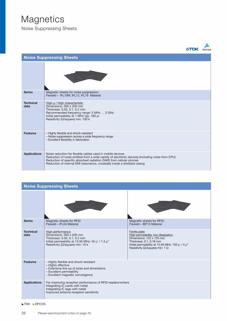
Series Magnetic sheets for noise suppressionFlexield – IFL10M, IFL12, IFL16 Material
Technicaldata
Features
Applications
Noise Suppressing Sheets
– Highly flexible and shock-resistant– Noise suppression across a wide frequency range– Excellent flexibility in fabrication
High µ / High characteristicDimensions: 300 x 200 mmThickness: 0.05, 0.1, 0.2 mmRecommended frequency range: 5 MHz … 3 GHzInitial permeability at 1 MHz typ: 180 µiResistivity (V/square) min: 100 k
Noise reduction for flexible cables used in mobile devicesReduction of noise emitted from a wide variety of electronic devices (including noise from CPU)Reduction of specific absorbed radiation (SAR) from cellular phonesReduction of internal EMI (resonance, crosstalk) inside a shielded casing
Series Magnetic sheets for RFID Magnetic sheets for RFIDFlexield – IFL04 Material Flexield – IBF15 Material
Technicaldata
Features
Applications
Noise Suppressing Sheets
– Highly flexible and shock-resistant– Highly effective – Extensive line-up of sizes and dimensions– Excellent permeability– Excellent magnetic convergence
High performance Dimensions: 300 x 200 mmThickness: 0.05, 0.1, 0.2 mmInitial permeability at 13.56 MHz: 45 µ’ / 1.3 µ’’Resistivity (V/square) min: 10 k
Ferrite plateHigh permeability, low dissipation Dimensions: 125 x 125 mmThickness: 0.1, 0.18 mmInitial permeability at 13.56 MHz: 150 µ’ / 5 µ’’Resistivity (V/square) min: 1 G
For improving reception performance of RFID readers/writersIntegrating IC cards with metalIntegrating IC tags with metalImproved antenna reception sensitivity
27© TDK-EPC Corporation 2010 Please read Important notes on page 76.
SAW ComponentsCeramic and Thin-Film RF Components
EPCOSTDK
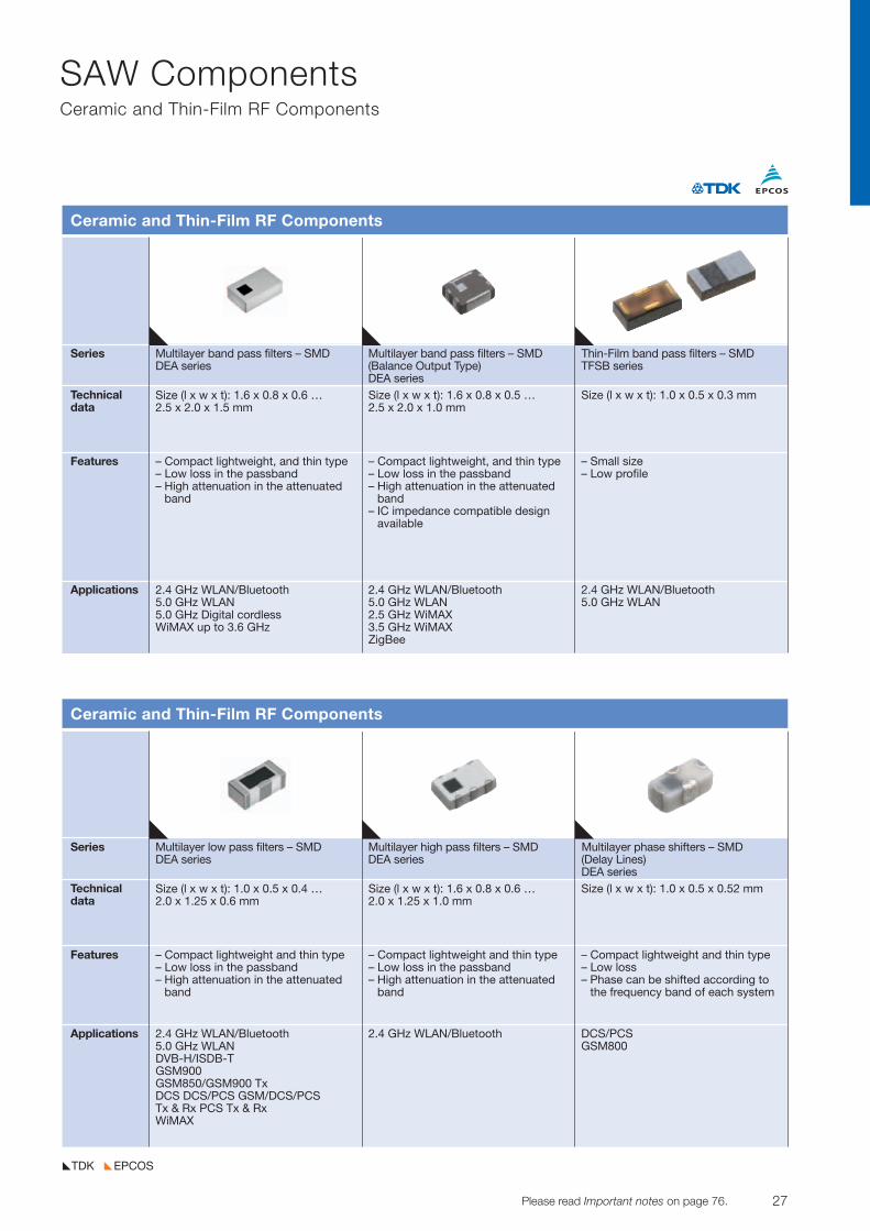
Series Multilayer band pass filters – SMD Multilayer band pass filters – SMD Thin-Film band pass filters – SMDDEA series (Balance Output Type) TFSB series
DEA seriesTechnicaldata
Features
Applications
Ceramic and Thin-Film RF Components
Size (l x w x t): 1.6 x 0.8 x 0.6 … 2.5 x 2.0 x 1.5 mm
– Compact lightweight, and thin type– Low loss in the passband– High attenuation in the attenuated
band
Size (l x w x t): 1.6 x 0.8 x 0.5 … 2.5 x 2.0 x 1.0 mm
– Compact lightweight, and thin type– Low loss in the passband– High attenuation in the attenuated
band– IC impedance compatible design
available
Size (l x w x t): 1.0 x 0.5 x 0.3 mm
– Small size– Low profile
2.4 GHz WLAN/Bluetooth5.0 GHz WLAN5.0 GHz Digital cordlessWiMAX up to 3.6 GHz
2.4 GHz WLAN/Bluetooth5.0 GHz WLAN2.5 GHz WiMAX3.5 GHz WiMAXZigBee
2.4 GHz WLAN/Bluetooth5.0 GHz WLAN
Series Multilayer low pass filters – SMD Multilayer high pass filters – SMD Multilayer phase shifters – SMDDEA series DEA series (Delay Lines)
DEA seriesTechnicaldata
Features
Applications
Ceramic and Thin-Film RF Components
Size (l x w x t): 1.0 x 0.5 x 0.4 … 2.0 x 1.25 x 0.6 mm
– Compact lightweight and thin type– Low loss in the passband– High attenuation in the attenuated
band
Size (l x w x t): 1.6 x 0.8 x 0.6 … 2.0 x 1.25 x 1.0 mm
– Compact lightweight and thin type– Low loss in the passband– High attenuation in the attenuated
band
Size (l x w x t): 1.0 x 0.5 x 0.52 mm
– Compact lightweight and thin type– Low loss– Phase can be shifted according to
the frequency band of each system
2.4 GHz WLAN/Bluetooth5.0 GHz WLANDVB-H/ISDB-T GSM900GSM850/GSM900 TxDCS DCS/PCS GSM/DCS/PCS Tx & Rx PCS Tx & RxWiMAX
2.4 GHz WLAN/Bluetooth DCS/PCSGSM800
28 Please read Important notes on page 76. © TDK-EPC Corporation 2010
SAW ComponentsCeramic and Thin-Film RF Components
EPCOSTDK
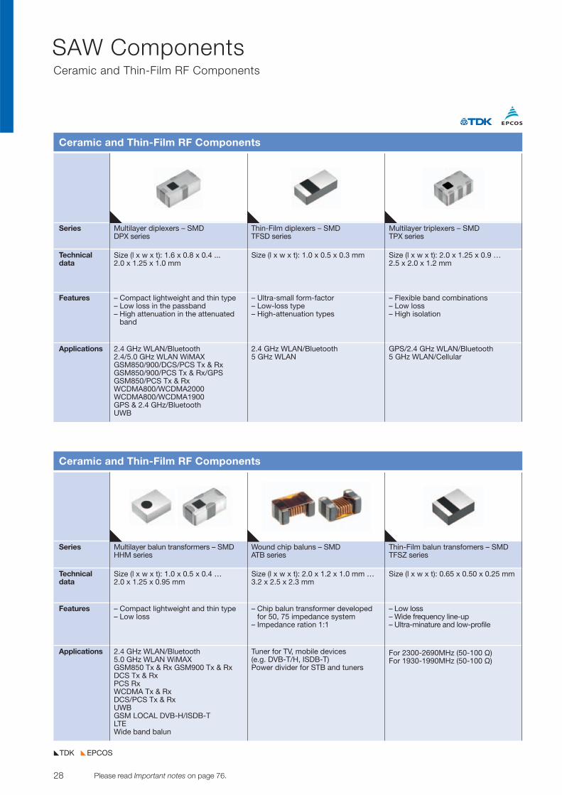
Series Multilayer diplexers – SMD Thin-Film diplexers – SMD Multilayer triplexers – SMDDPX series TFSD series TPX series
Technicaldata
Features
Applications
Ceramic and Thin-Film RF Components
Size (l x w x t): 1.6 x 0.8 x 0.4 ... 2.0 x 1.25 x 1.0 mm
– Compact lightweight and thin type– Low loss in the passband– High attenuation in the attenuated
band
Size (l x w x t): 1.0 x 0.5 x 0.3 mm
– Ultra-small form-factor– Low-loss type– High-attenuation types
Size (l x w x t): 2.0 x 1.25 x 0.9 … 2.5 x 2.0 x 1.2 mm
– Flexible band combinations– Low loss– High isolation
2.4 GHz WLAN/Bluetooth2.4/5.0 GHz WLAN WiMAXGSM850/900/DCS/PCS Tx & RxGSM850/900/PCS Tx & Rx/GPSGSM850/PCS Tx & RxWCDMA800/WCDMA2000WCDMA800/WCDMA1900GPS & 2.4 GHz/BluetoothUWB
2.4 GHz WLAN/Bluetooth5 GHz WLAN
GPS/2.4 GHz WLAN/Bluetooth5 GHz WLAN/Cellular
Series Multilayer balun transformers – SMD Wound chip baluns – SMD Thin-Film balun transfomers – SMDHHM series ATB series TFSZ series
Technicaldata
Features
Applications
Ceramic and Thin-Film RF Components
Size (l x w x t): 1.0 x 0.5 x 0.4 … 2.0 x 1.25 x 0.95 mm
– Compact lightweight and thin type– Low loss
Size (l x w x t): 2.0 x 1.2 x 1.0 mm …3.2 x 2.5 x 2.3 mm
– Chip balun transformer developedfor 50, 75 impedance system
– Impedance ration 1:1
Size (l x w x t): 0.65 x 0.50 x 0.25 mm
– Low loss– Wide frequency line-up– Ultra-minature and low-profile
2.4 GHz WLAN/Bluetooth5.0 GHz WLAN WiMAXGSM850 Tx & Rx GSM900 Tx & RxDCS Tx & RxPCS RxWCDMA Tx & RxDCS/PCS Tx & RxUWBGSM LOCAL DVB-H/ISDB-TLTEWide band balun
Tuner for TV, mobile devices (e.g. DVB-T/H, ISDB-T)Power divider for STB and tuners
For 2300-2690MHz (50-100 V)For 1930-1990MHz (50-100 V)
29© TDK-EPC Corporation 2010 Please read Important notes on page 76.
SAW ComponentsCeramic and Thin-Film RF Components, LTCC Substrates for LED
EPCOSTDK
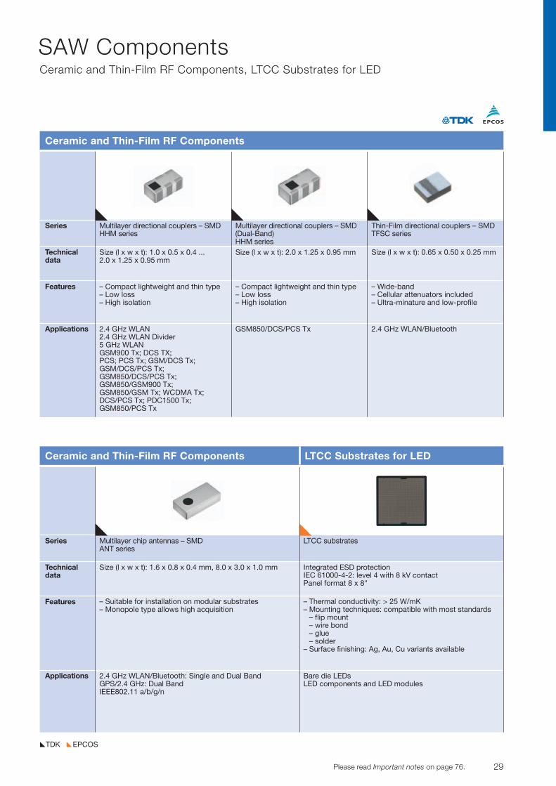
Series Multilayer directional couplers – SMD Multilayer directional couplers – SMD Thin-Film directional couplers – SMD HHM series (Dual-Band) TFSC series
HHM seriesTechnicaldata
Features
Applications
Ceramic and Thin-Film RF Components
Size (l x w x t): 1.0 x 0.5 x 0.4 ... 2.0 x 1.25 x 0.95 mm
– Compact lightweight and thin type– Low loss– High isolation
Size (l x w x t): 2.0 x 1.25 x 0.95 mm
– Compact lightweight and thin type– Low loss– High isolation
Size (l x w x t): 0.65 x 0.50 x 0.25 mm
– Wide-band– Cellular attenuators included– Ultra-minature and low-profile
2.4 GHz WLAN2.4 GHz WLAN Divider5 GHz WLANGSM900 Tx; DCS TX;PCS; PCS Tx; GSM/DCS Tx;GSM/DCS/PCS Tx; GSM850/DCS/PCS Tx;GSM850/GSM900 Tx; GSM850/GSM Tx; WCDMA Tx;DCS/PCS Tx; PDC1500 Tx;GSM850/PCS Tx
2.4 GHz WLAN/BluetoothGSM850/DCS/PCS Tx
Series Multilayer chip antennas – SMD LTCC substratesANT series
Technicaldata
Features
Applications
Ceramic and Thin-Film RF Components LTCC Substrates for LED
Size (l x w x t): 1.6 x 0.8 x 0.4 mm, 8.0 x 3.0 x 1.0 mm
– Suitable for installation on modular substrates– Monopole type allows high acquisition
– Thermal conductivity: > 25 W/mK– Mounting techniques: compatible with most standards
– flip mount– wire bond– glue– solder
– Surface finishing: Ag, Au, Cu variants available
2.4 GHz WLAN/Bluetooth: Single and Dual BandGPS/2.4 GHz: Dual BandIEEE802.11 a/b/g/n
Bare die LEDs LED components and LED modules
Integrated ESD protectionIEC 61000-4-2: level 4 with 8 kV contact Panel format 8 x 8"
30 Please read Important notes on page 76. © TDK-EPC Corporation 2010
MEMS DevicesMEMS Devices for Mobile Communications and Information Technology
EPCOSTDK
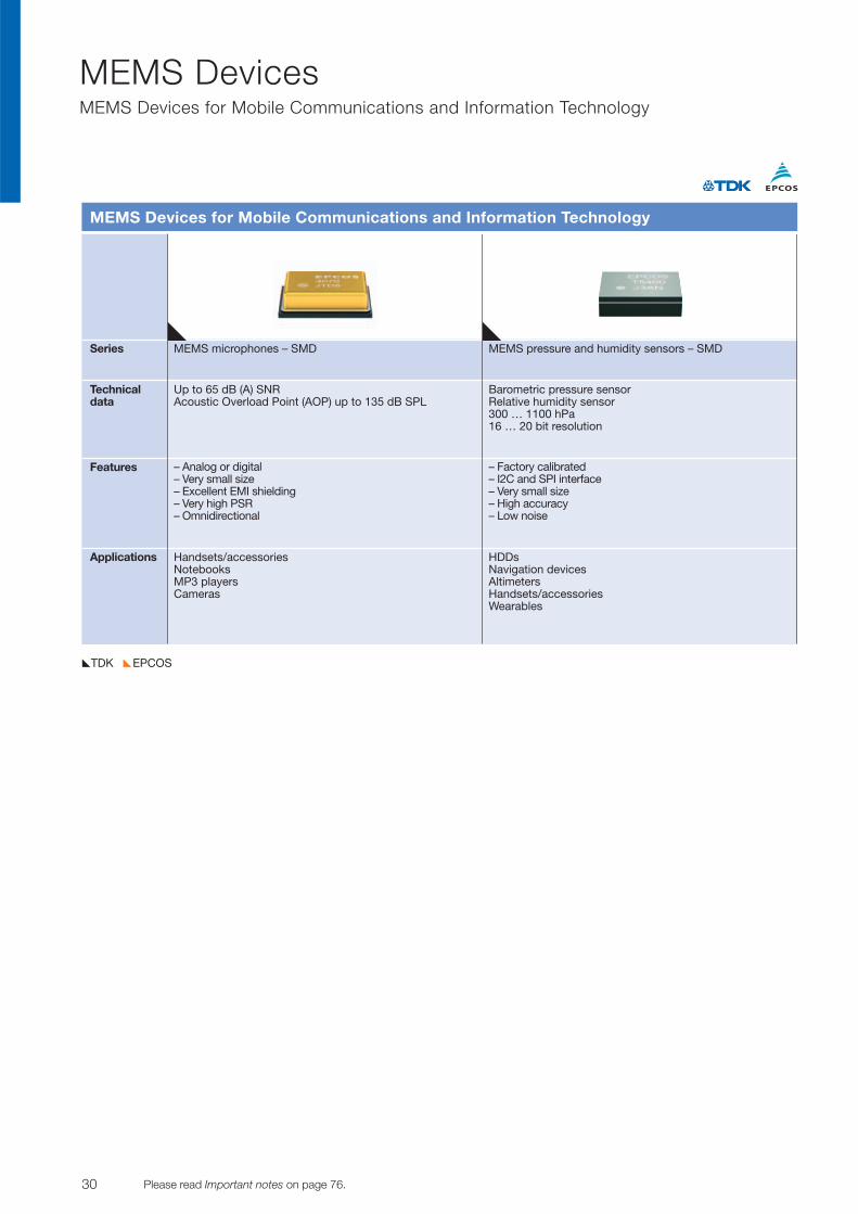
Series MEMS microphones – SMD MEMS pressure and humidity sensors – SMD
Technicaldata
Features
Applications
MEMS Devices for Mobile Communications and Information Technology
Up to 65 dB (A) SNRAcoustic Overload Point (AOP) up to 135 dB SPL
– Analog or digital– Very small size– Excellent EMI shielding– Very high PSR– Omnidirectional
– Factory calibrated– I2C and SPI interface– Very small size– High accuracy– Low noise
Handsets/accessoriesNotebooks MP3 players Cameras
HDDsNavigation devicesAltimetersHandsets/accessoriesWearables
Barometric pressure sensorRelative humidity sensor300 … 1100 hPa16 … 20 bit resolution
31© TDK-EPC Corporation 2010 Please read Important notes on page 76.
Micro Modules Bluetooth V4.1 Smart Single Mode Module
EPCOSTDK
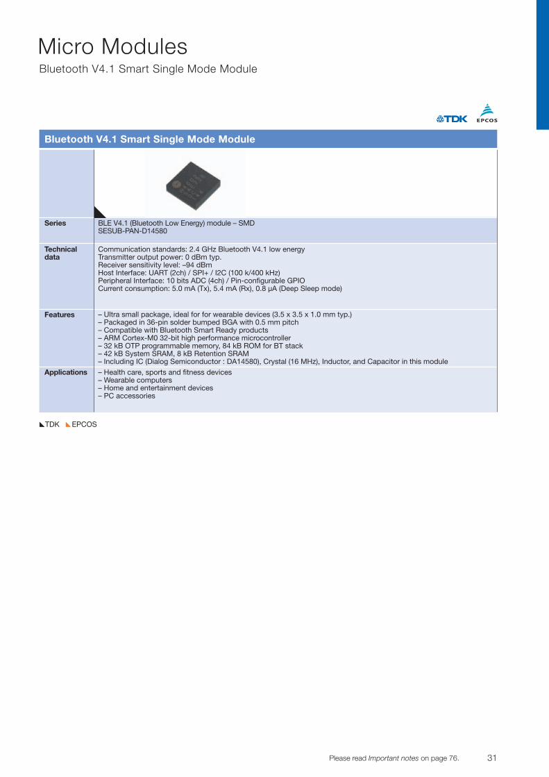
Series BLE V4.1 (Bluetooth Low Energy) module – SMDSESUB-PAN-D14580
Technicaldata
Features
Applications
Bluetooth V4.1 Smart Single Mode Module
Communication standards: 2.4 GHz Bluetooth V4.1 low energyTransmitter output power: 0 dBm typ.Receiver sensitivity level: –94 dBmHost Interface: UART (2ch) / SPI+ / I2C (100 k/400 kHz)Peripheral Interface: 10 bits ADC (4ch) / Pin-configurable GPIOCurrent consumption: 5.0 mA (Tx), 5.4 mA (Rx), 0.8 µA (Deep Sleep mode)
– Ultra small package, ideal for for wearable devices (3.5 x 3.5 x 1.0 mm typ.) – Packaged in 36-pin solder bumped BGA with 0.5 mm pitch – Compatible with Bluetooth Smart Ready products – ARM Cortex-M0 32-bit high performance microcontroller – 32 kB OTP programmable memory, 84 kB ROM for BT stack – 42 kB System SRAM, 8 kB Retention SRAM – Including IC (Dialog Semiconductor : DA14580), Crystal (16 MHz), Inductor, and Capacitor in this module
– Health care, sports and fitness devices– Wearable computers– Home and entertainment devices– PC accessories
32 Please read Important notes on page 76. © TDK-EPC Corporation 2010
Piezo and Protection DevicesPiezo Actuators for Automotive, Piezo Receivers, Buzzers
EPCOSTDK
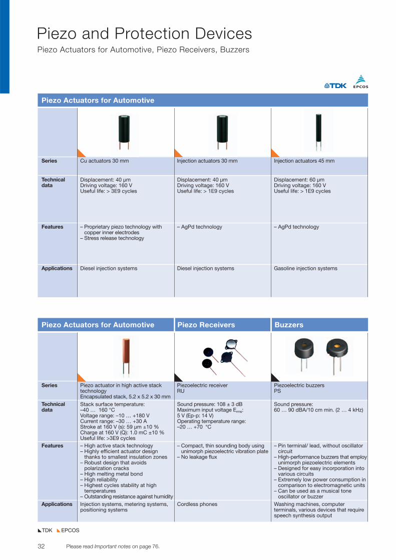
Series Cu actuators 30 mm Injection actuators 30 mm Injection actuators 45 mm
Technicaldata
Features
Applications
Piezo Actuators for Automotive
Displacement: 40 µm Driving voltage: 160 V Useful life: > 3E9 cycles
– Proprietary piezo technology with copper inner electrodes
– Stress release technology
Displacement: 40 µm Driving voltage: 160 V Useful life: > 1E9 cycles
– AgPd technology
Displacement: 60 µm Driving voltage: 160 VUseful life: > 1E9 cycles
– AgPd technology
Diesel injection systems Diesel injection systems Gasoline injection systems
Series Piezo actuator in high active stack Piezoelectric receiver Piezoelectric buzzerstechnology RU PSEncapsulated stack, 5.2 x 5.2 x 30 mm
Technicaldata
Features
Applications
Piezo Actuators for Automotive Piezo Receivers Buzzers
Stack surface temperature:–40 … 160 °CVoltage range: –10 … +180 VCurrent range: –30 … +30 AStroke at 160 V (s): 59 µm ±10 %Charge at 160 V (Q): 1.0 mC ±10 %Useful life: >3E9 cycles– High active stack technology– Highly efficient actuator design
thanks to smallest insulation zones– Robust design that avoids
polarization cracks– High melting metal bond– High reliability– Highest cycles stability at high
temperatures– Outstanding resistance against humidity
Sound pressure: 108 ± 3 dBMaximum input voltage Erms: 5 V (Ep-p: 14 V)Operating temperature range: –20 … +70 °C
– Compact, thin sounding body usingunimorph piezoelectric vibration plate
– No leakage flux
Sound pressure: 60 … 90 dBA/10 cm min. (2 … 4 kHz)
– Pin terminal/ lead, without oscillatorcircuit
– High-performance buzzers that employunimorph piezoelectric elements
– Designed for easy incorporation intovarious circuits
– Extremely low power consumption incomparison to electromagnetic units
– Can be used as a musical tone oscillator or buzzer
Injection systems, metering systems,positioning systems
Cordless phones Washing machines, computer terminals, various devices that requirespeech synthesis output
33© TDK-EPC Corporation 2010 Please read Important notes on page 76.
Piezo and Protection DevicesBuzzers, Surge Arresters
EPCOSTDK
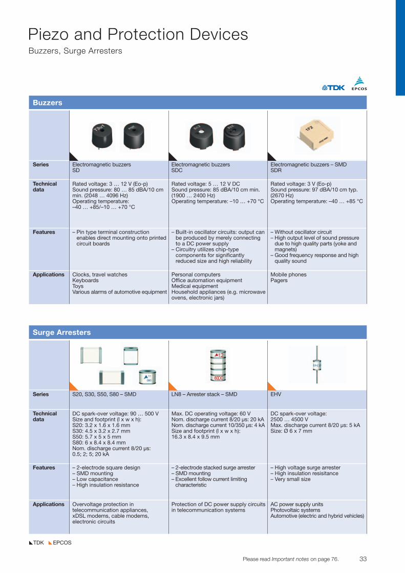
Series Electromagnetic buzzers Electromagnetic buzzers Electromagnetic buzzers – SMDSD SDC SDR
Technicaldata
Features
Applications
Buzzers
Rated voltage: 3 … 12 V (Eo-p)Sound pressure: 80 … 85 dBA/10 cmmin. (2048 … 4096 Hz)Operating temperature: –40 … +85/–10 … +70 °C
– Pin type terminal construction enables direct mounting onto printedcircuit boards
Rated voltage: 5 … 12 V DCSound pressure: 85 dBA/10 cm min.(1900 … 2400 Hz)Operating temperature: –10 … +70 °C
– Built-in oscillator circuits: output canbe produced by merely connecting to a DC power supply
– Circuitry utilizes chip-type components for significantly reduced size and high reliability
Rated voltage: 3 V (Eo-p)Sound pressure: 97 dBA/10 cm typ.(2670 Hz)Operating temperature: –40 … +85 °C
– Without oscillator circuit– High output level of sound pressure
due to high quality parts (yoke andmagnets)
– Good frequency response and highquality sound
Clocks, travel watchesKeyboardsToysVarious alarms of automotive equipment
Personal computersOffice automation equipmentMedical equipmentHousehold appliances (e.g. microwaveovens, electronic jars)
Mobile phonesPagers
Series S20, S30, S50, S80 – SMD LN8 – Arrester stack – SMD EHV
Technicaldata
Features
Applications
Surge Arresters
DC spark-over voltage: 90 … 500 V Size and footprint (l x w x h):S20: 3.2 x 1.6 x 1.6 mmS30: 4.5 x 3.2 x 2.7 mmS50: 5.7 x 5 x 5 mmS80: 6 x 8.4 x 8.4 mmNom. discharge current 8/20 µs: 0.5; 2; 5; 20 kA
– 2-electrode square design– SMD mounting– Low capacitance– High insulation resistance
Max. DC operating voltage: 60 VNom. discharge current 8/20 µs: 20 kANom. discharge current 10/350 µs: 4 kASize and footprint (l x w x h): 16.3 x 8.4 x 9.5 mm
– 2-electrode stacked surge arrester– SMD mounting– Excellent follow current limiting
characteristic
DC spark-over voltage: 2500 … 4500 V Max. discharge current 8/20 µs: 5 kASize: Ø 6 x 7 mm
– High voltage surge arrester– High insulation resisitance– Very small size
Overvoltage protection in telecommunication appliances, xDSL modems, cable modems, electronic circuits
Protection of DC power supply circuitsin telecommunication systems
AC power supply unitsPhotovoltaic systemsAutomotive (electric and hybrid vehicles)
34 Please read Important notes on page 76. © TDK-EPC Corporation 2010
Piezo and Protection DevicesSurge Arresters
EPCOSTDK
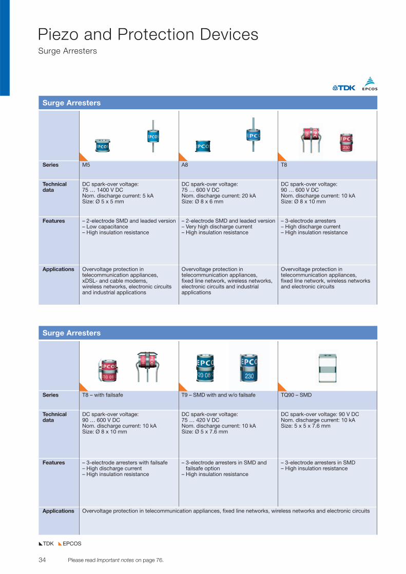
Series T8 – with failsafe T9 – SMD with and w/o failsafe TQ90 – SMD
Technicaldata
Features
Applications
Surge Arresters
DC spark-over voltage: 90 … 600 V DCNom. discharge current: 10 kASize: Ø 8 x 10 mm
– 3-electrode arresters with failsafe– High discharge current– High insulation resistance
DC spark-over voltage: 75 … 420 V DCNom. discharge current: 10 kASize: Ø 5 x 7.6 mm
– 3-electrode arresters in SMD and failsafe option
– High insulation resistance
DC spark-over voltage: 90 V DCNom. discharge current: 10 kASize: 5 x 5 x 7.6 mm
– 3-electrode arresters in SMD – High insulation resistance
Overvoltage protection in telecommunication appliances, fixed line networks, wireless networks and electronic circuits
Series M5 A8 T8
Technicaldata
Features
Applications
Surge Arresters
DC spark-over voltage: 75 … 1400 V DCNom. discharge current: 5 kASize: Ø 5 x 5 mm
– 2-electrode SMD and leaded version– Low capacitance– High insulation resistance
DC spark-over voltage: 75 … 600 V DCNom. discharge current: 20 kASize: Ø 8 x 6 mm
– 2-electrode SMD and leaded version– Very high discharge current– High insulation resistance
DC spark-over voltage: 90 … 600 V DCNom. discharge current: 10 kASize: Ø 8 x 10 mm
– 3-electrode arresters– High discharge current– High insulation resistance
Overvoltage protection in telecommunication appliances, xDSL- and cable modems, wireless networks, electronic circuitsand industrial applications
Overvoltage protection in telecommunication appliances, fixed line network, wireless networks,electronic circuits and industrial applications
Overvoltage protection in telecommunication appliances, fixed line network, wireless networksand electronic circuits
35© TDK-EPC Corporation 2010 Please read Important notes on page 76.
Piezo and Protection DevicesSurge Arresters, PTC Thermistors
EPCOSTDK
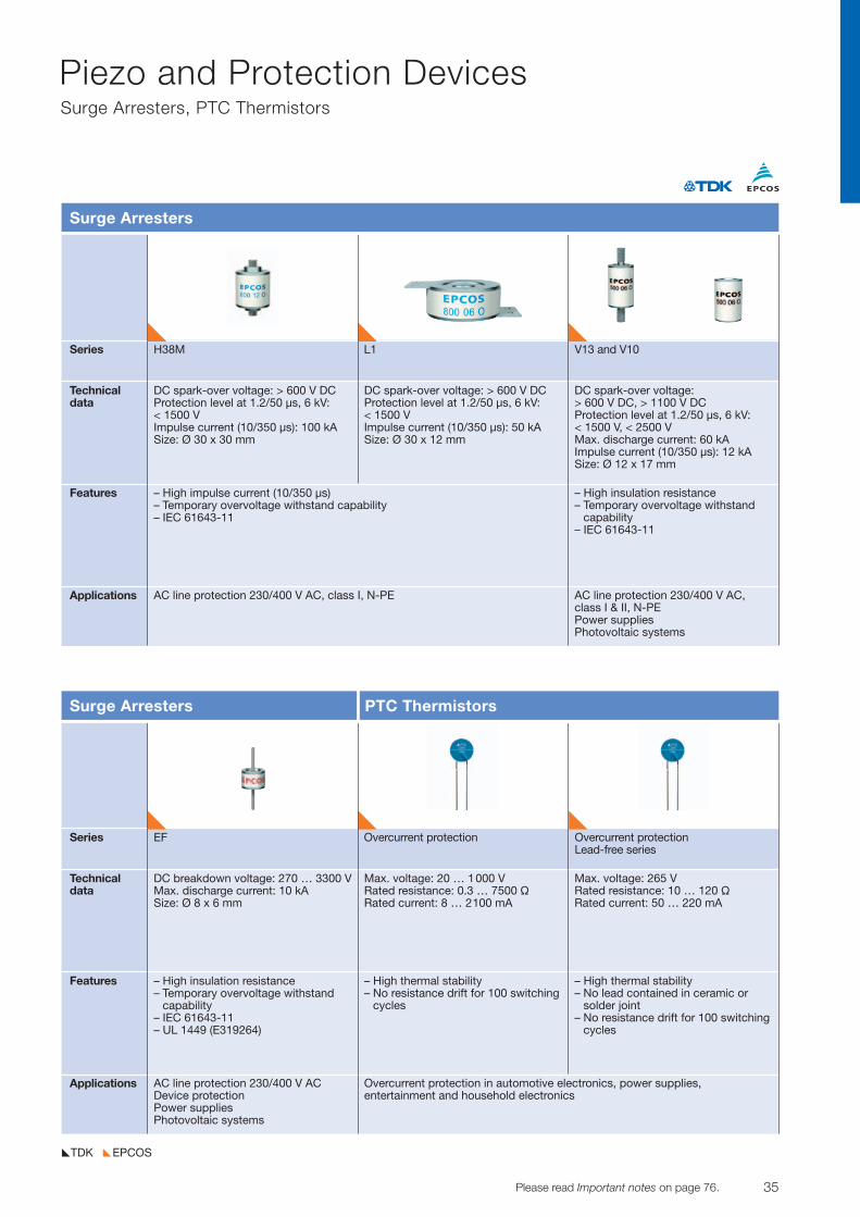
Surge Arresters PTC Thermistors
Series H38M L1 V13 and V10
Technicaldata
Features
Applications
Surge Arresters
DC spark-over voltage: > 600 V DCProtection level at 1.2/50 µs, 6 kV:< 1500 VImpulse current (10/350 µs): 100 kA Size: Ø 30 x 30 mm
– High impulse current (10/350 µs)– Temporary overvoltage withstand capability– IEC 61643-11
DC spark-over voltage: > 600 V DCProtection level at 1.2/50 µs, 6 kV:< 1500 VImpulse current (10/350 µs): 50 kA Size: Ø 30 x 12 mm
DC spark-over voltage:> 600 V DC, > 1100 V DCProtection level at 1.2/50 µs, 6 kV:< 1500 V, < 2500 VMax. discharge current: 60 kAImpulse current (10/350 µs): 12 kA Size: Ø 12 x 17 mm
– High insulation resistance– Temporary overvoltage withstand
capability– IEC 61643-11
AC line protection 230/400 V AC, class I, N-PE AC line protection 230/400 V AC, class I & II, N-PEPower suppliesPhotovoltaic systems
Series EF Overcurrent protection Overcurrent protectionLead-free series
Technicaldata
Features
Applications
DC breakdown voltage: 270 … 3300 VMax. discharge current: 10 kASize: Ø 8 x 6 mm
– High insulation resistance– Temporary overvoltage withstand
capability– IEC 61643-11– UL 1449 (E319264)
Max. voltage: 20 … 1000 VRated resistance: 0.3 … 7500 VRated current: 8 … 2100 mA
– High thermal stability– No resistance drift for 100 switching
cycles
Max. voltage: 265 VRated resistance: 10 … 120 VRated current: 50 … 220 mA
– High thermal stability– No lead contained in ceramic or
solder joint– No resistance drift for 100 switching
cycles
AC line protection 230/400 V ACDevice protectionPower suppliesPhotovoltaic systems
Overcurrent protection in automotive electronics, power supplies, entertainment and household electronics
36 Please read Important notes on page 76. © TDK-EPC Corporation 2010
Piezo and Protection DevicesPTC Thermistors
EPCOSTDK
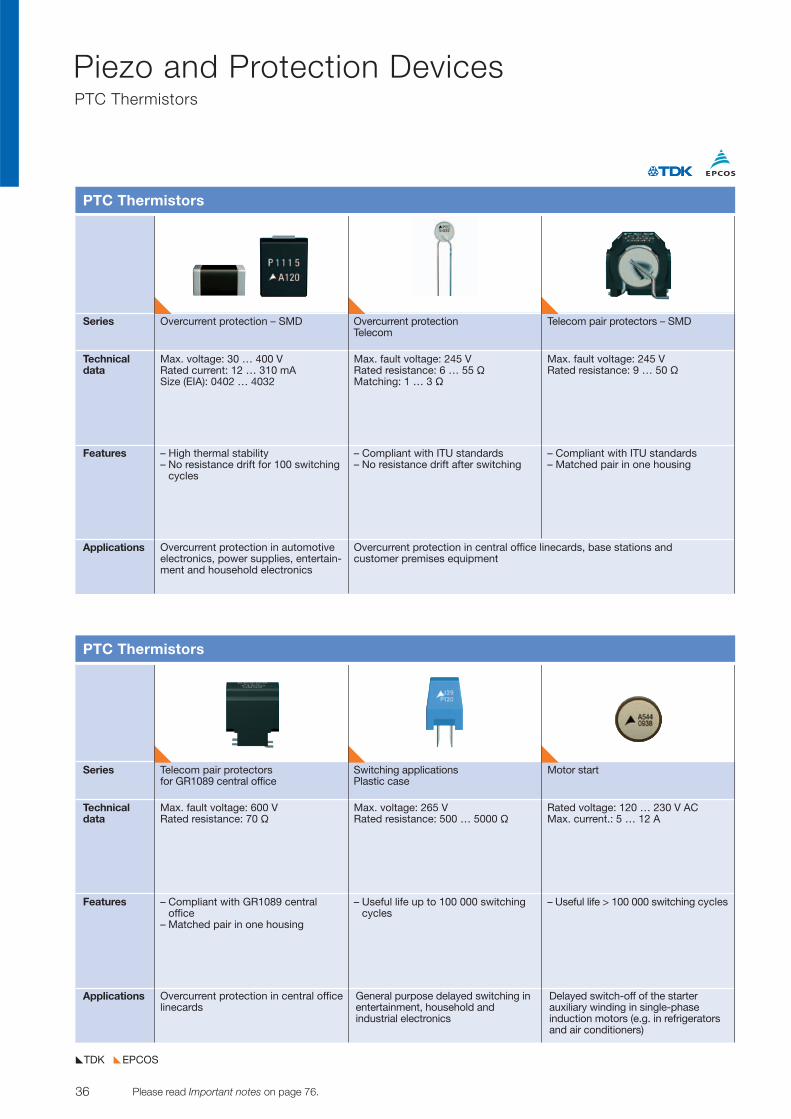
Series Overcurrent protection – SMD Overcurrent protection Telecom pair protectors – SMDTelecom
Technicaldata
Features
Applications
PTC Thermistors
Max. voltage: 30 … 400 VRated current: 12 … 310 mASize (EIA): 0402 … 4032
– High thermal stability– No resistance drift for 100 switching
cycles
Max. fault voltage: 245 VRated resistance: 6 … 55 VMatching: 1 … 3 V
– Compliant with ITU standards– No resistance drift after switching
Max. fault voltage: 245 VRated resistance: 9 … 50 V
– Compliant with ITU standards– Matched pair in one housing
Overcurrent protection in automotiveelectronics, power supplies, entertain-ment and household electronics
Overcurrent protection in central office linecards, base stations and customer premises equipment
Series Telecom pair protectors Switching applications Motor startfor GR1089 central office Plastic case
Technicaldata
Features
Applications
PTC Thermistors
Max. fault voltage: 600 VRated resistance: 70 V
– Compliant with GR1089 central office
– Matched pair in one housing
Max. voltage: 265 VRated resistance: 500 … 5000 V
– Useful life up to 100 000 switchingcycles
Rated voltage: 120 … 230 V ACMax. current.: 5 … 12 A
– Useful life > 100 000 switching cycles
Overcurrent protection in central officelinecards
General purpose delayed switching inentertainment, household and industrial electronics
Delayed switch-off of the starter auxiliary winding in single-phase induction motors (e.g. in refrigeratorsand air conditioners)
37© TDK-EPC Corporation 2010 Please read Important notes on page 76.
Piezo and Protection DevicesPTC Thermistors
EPCOSTDK
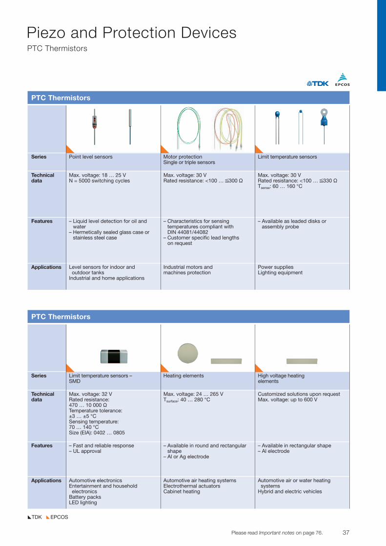
Series Limit temperature sensors – Heating elements High voltage heating SMD elements
Technicaldata
Features
Applications
PTC Thermistors
Max. voltage: 32 VRated resistance: 470 … 10 000 VTemperature tolerance:±3 … ±5 °CSensing temperature: 70 … 140 °CSize (EIA): 0402 … 0805
– Fast and reliable response– UL approval
Max. voltage: 24 … 265 VTsurface: 40 … 280 °C
– Available in round and rectangularshape
– Al or Ag electrode
Customized solutions upon requestMax. voltage: up to 600 V
– Available in rectangular shape– Al electrode
Automotive electronicsEntertainment and household electronics
Battery packsLED lighting
Automotive air heating systemsElectrothermal actuatorsCabinet heating
Automotive air or water heating systems
Hybrid and electric vehicles
Series Point level sensors Motor protection Limit temperature sensorsSingle or triple sensors
Technicaldata
Features
Applications
PTC Thermistors
Max. voltage: 18 … 25 VN = 5000 switching cycles
– Liquid level detection for oil and water
– Hermetically sealed glass case orstainless steel case
Max. voltage: 30 VRated resistance: <100 … ≤300 V
– Characteristics for sensing temperatures compliant with DIN 44081/44082
– Customer specific lead lengths on request
Max. voltage: 30 VRated resistance: <100 … ≤330 VTsense: 60 … 160 °C
– Available as leaded disks or assembly probe
Level sensors for indoor andoutdoor tanks
Industrial and home applications
Industrial motors and machines protection
Power suppliesLighting equipment
38 Please read Important notes on page 76. © TDK-EPC Corporation 2010
Piezo and Protection DevicesVaristors
EPCOSTDK
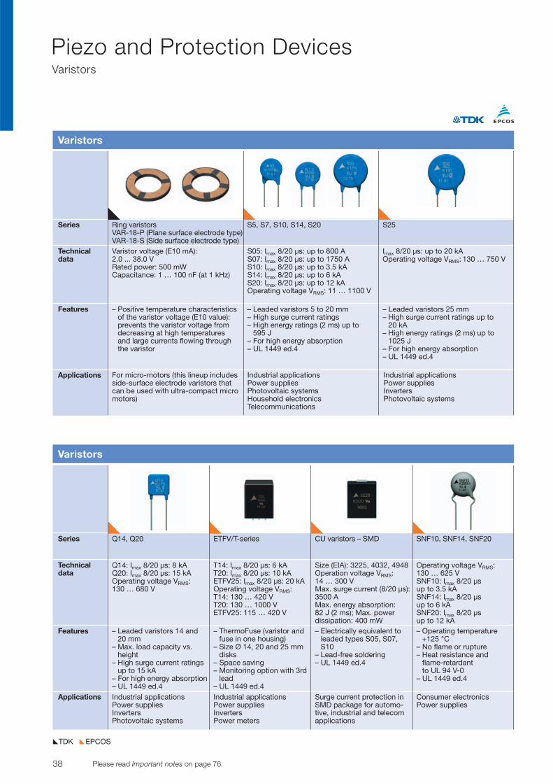
Series Q14, Q20 ETFV/T-series CU varistors – SMD SNF10, SNF14, SNF20
Technical data
Features
Applications
Varistors
Q14: Imax 8/20 µs: 8 kAQ20: Imax 8/20 µs: 15 kAOperating voltage VRMS: 130 … 680 V
– Leaded varistors 14 and20 mm
– Max. load capacity vs.height
– High surge current ratingsup to 15 kA
– For high energy absorption– UL 1449 ed.4
T14: Imax 8/20 µs: 6 kAT20: Imax 8/20 µs: 10 kAETFV25: Imax 8/20 µs: 20 kAOperating voltage VRMS: T14: 130 … 420 VT20: 130 … 1000 V ETFV25: 115 … 420 V
– ThermoFuse (varistor andfuse in one housing)
– Size Ø 14, 20 and 25 mmdisks
– Space saving– Monitoring option with 3rd
lead– UL 1449 ed.4
Size (EIA): 3225, 4032, 4948Operation voltage VRMS: 14 … 300 VMax. surge current (8/20 µs):3500 A Max. energy absorption:82 J (2 ms); Max. power dissipation: 400 mW– Electrically equivalent to
leaded types S05, S07,S10
– Lead-free soldering– UL 1449 ed.4
Operating voltage VRMS: 130 … 625 VSNF10: Imax 8/20 µs up to 3.5 kASNF14: Imax 8/20 µs up to 6 kASNF20: Imax 8/20 µs up to 12 kA– Operating temperature
+125 °C– No flame or rupture– Heat resistance and
flame-retardant to UL 94 V-0
– UL 1449 ed.4
Industrial applicationsPower suppliesInvertersPhotovoltaic systems
Consumer electronicsPower supplies
Industrial applicationsPower suppliesInvertersPower meters
Surge current protection inSMD package for automo-tive, industrial and telecomapplications
Series Ring varistors S5, S7, S10, S14, S20 S25VAR-18-P (Plane surface electrode type)VAR-18-S (Side surface electrode type)
Technicaldata
Features
Applications
Varistors
Varistor voltage (E10 mA): 2.0 ... 38.0 VRated power: 500 mWCapacitance: 1 … 100 nF (at 1 kHz)
– Positive temperature characteristicsof the varistor voltage (E10 value):prevents the varistor voltage fromdecreasing at high temperaturesand large currents flowing throughthe varistor
S05: Imax 8/20 µs: up to 800 AS07: Imax 8/20 µs: up to 1750 AS10: Imax 8/20 µs: up to 3.5 kAS14: Imax 8/20 µs: up to 6 kAS20: Imax 8/20 µs: up to 12 kAOperating voltage VRMS: 11 … 1100 V
– Leaded varistors 5 to 20 mm– High surge current ratings – High energy ratings (2 ms) up to
595 J– For high energy absorption– UL 1449 ed.4
Imax 8/20 µs: up to 20 kAOperating voltage VRMS: 130 … 750 V
– Leaded varistors 25 mm– High surge current ratings up to
20 kA – High energy ratings (2 ms) up to
1025 J– For high energy absorption– UL 1449 ed.4
For micro-motors (this lineup includesside-surface electrode varistors thatcan be used with ultra-compact micromotors)
Industrial applicationsPower suppliesPhotovoltaic systemsHousehold electronicsTelecommunications
Industrial applicationsPower suppliesInvertersPhotovoltaic systems
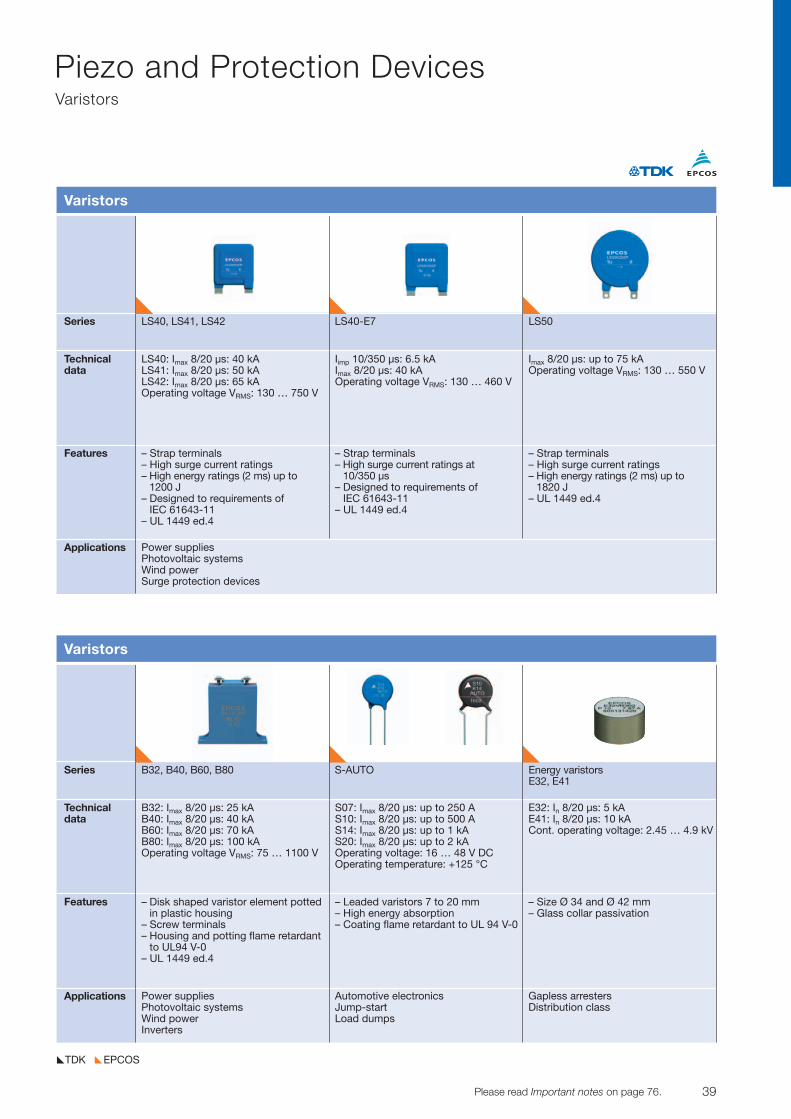
39© TDK-EPC Corporation 2010 Please read Important notes on page 76.
Piezo and Protection DevicesVaristors
EPCOSTDK
Series LS40, LS41, LS42 LS40-E7 LS50
Technicaldata
Features
Applications
Varistors
LS40: Imax 8/20 µs: 40 kALS41: Imax 8/20 µs: 50 kALS42: Imax 8/20 µs: 65 kA Operating voltage VRMS: 130 … 750 V
– Strap terminals– High surge current ratings – High energy ratings (2 ms) up to
1200 J– Designed to requirements of
IEC 61643-11– UL 1449 ed.4
Iimp 10/350 µs: 6.5 kAImax 8/20 µs: 40 kAOperating voltage VRMS: 130 … 460 V
– Strap terminals– High surge current ratings at
10/350 µs– Designed to requirements of
IEC 61643-11– UL 1449 ed.4
Imax 8/20 µs: up to 75 kAOperating voltage VRMS: 130 … 550 V
– Strap terminals– High surge current ratings – High energy ratings (2 ms) up to
1820 J– UL 1449 ed.4
Power suppliesPhotovoltaic systemsWind powerSurge protection devices
Series B32, B40, B60, B80 S-AUTO Energy varistorsE32, E41
Technicaldata
Features
Applications
Varistors
B32: Imax 8/20 µs: 25 kAB40: Imax 8/20 µs: 40 kAB60: Imax 8/20 µs: 70 kAB80: Imax 8/20 µs: 100 kAOperating voltage VRMS: 75 … 1100 V
– Disk shaped varistor element potted in plastic housing
– Screw terminals– Housing and potting flame retardant
to UL94 V-0– UL 1449 ed.4
S07: Imax 8/20 µs: up to 250 AS10: Imax 8/20 µs: up to 500 AS14: Imax 8/20 µs: up to 1 kAS20: Imax 8/20 µs: up to 2 kAOperating voltage: 16 … 48 V DCOperating temperature: +125 °C
– Leaded varistors 7 to 20 mm– High energy absorption– Coating flame retardant to UL 94 V-0
E32: In 8/20 µs: 5 kAE41: In 8/20 µs: 10 kACont. operating voltage: 2.45 … 4.9 kV
– Size Ø 34 and Ø 42 mm– Glass collar passivation
Power suppliesPhotovoltaic systemsWind powerInverters
Automotive electronicsJump-startLoad dumps
Gapless arrestersDistribution class
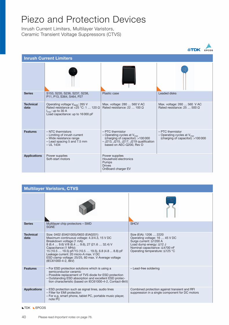
40 Please read Important notes on page 76. © TDK-EPC Corporation 2010
Piezo and Protection DevicesInrush Current Limiters, Multilayer Varistors, Ceramic Transient Voltage Suppressors (CTVS)
EPCOSTDK
Series S153, S235, S236, S237, S238, Plastic case Leaded disksP11, P13, S364, S464, P27
Technicaldata
Features
Applications
Inrush Current Limiters
Operating voltage VRMS: 265 VRated resistance at +25 °C: 1 … 120 VImax: up to 30 ALoad capacitance: up to 16 000 pF
– NTC thermistors– Limiting of inrush current– Wide resistance range– Lead spacing 5 and 7.5 mm– UL 1434
Max. voltage: 280 … 560 V ACRated resistance: 22 … 100 V
– PTC thermistor– Operating cycles at Vmax
(charging of capacitor): >100 000– J213, J215, J217, J219 qualification
based on AEC-Q200, Rev D
Max. voltage: 260 … 560 V ACRated resistance: 25 … 500 V
– PTC thermistor– Operating cycles at Vmax
(charging of capacitor): >100 000
Power suppliesSoft-start motors
Power suppliesHousehold electronicsPumpsDrivesOnBoard charger EV
Series Multilayer chip protectors – SMD SHCVSGNE
Technicaldata
Features
Applications
Multilayer Varistors, CTVS
Size: 0402 (EIA01005)/0603 (EIA0201)Maximum continuous voltage: 4.3/4.3, 15 V DCBreakdown voltage (1 mA): 8 (6.4 … 9.6) V/8 (6.4 … 9.6), 27 (21.6 … 32.4) VCapacitance (1 MHz): 15 (10.5 … 19.5) pF/15 (10.5 … 19.5), 6.8 (4.8 ... 8.8) pFLeakage current: 20 micro-A max. V DCESD clamp voltage: 25/25, 60 max. V Average voltage(IEC61000-4-2, 8kV)
– For ESD protection solutions which is using a semiconductor ceramic
– Possible replacement of TVS diode for ESD protection – Outstanding ESD absorption and excellent ESD protec-
tion characteristic (based on IEC61000-4-2, Contact-8kV)
– Lead-free soldering
– ESD protection such as signal lines, audio lines – Filter for EMI protection – For e.g. smart phone, tablet PC, portable music player,
note PC
Combined protection against transient and RFI suppression in a single component for DC motors
Size (EIA): 1206 … 2220Operating voltage: 16 … 45 V DCSurge current: ≤1200 ALoad dump energy: ≤12 JNominal capacitance: ≤4700 nFOperating temperature: ≤125 °C
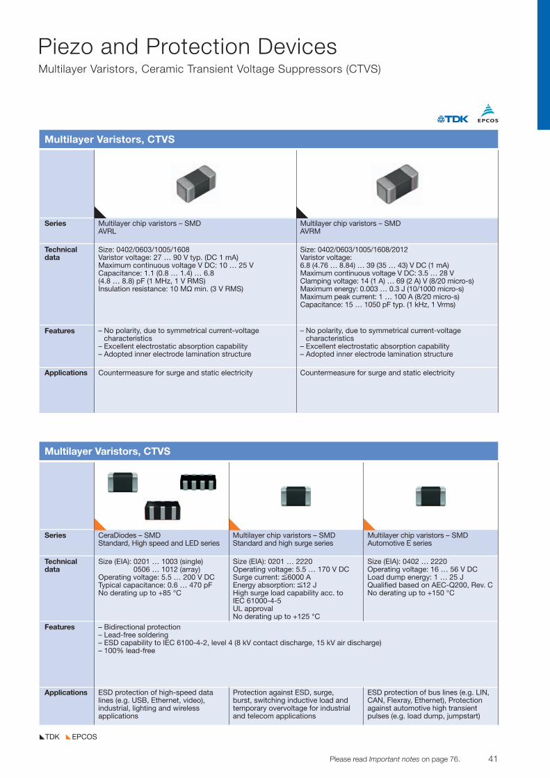
41© TDK-EPC Corporation 2010 Please read Important notes on page 76.
Piezo and Protection DevicesMultilayer Varistors, Ceramic Transient Voltage Suppressors (CTVS)
EPCOSTDK
Series CeraDiodes – SMD Multilayer chip varistors – SMD Multilayer chip varistors – SMDStandard, High speed and LED series Standard and high surge series Automotive E series
Technicaldata
Features
Applications
Multilayer Varistors, CTVS
Size (EIA): 0201 … 1003 (single)0506 … 1012 (array)
Operating voltage: 5.5 … 200 V DCTypical capacitance: 0.6 … 470 pFNo derating up to +85 °C
– Bidirectional protection– Lead-free soldering– ESD capability to IEC 6100-4-2, level 4 (8 kV contact discharge, 15 kV air discharge)– 100% lead-free
Size (EIA): 0201 … 2220Operating voltage: 5.5 … 170 V DCSurge current: ≤6000 AEnergy absorption: ≤12 JHigh surge load capability acc. to IEC 61000-4-5UL approvalNo derating up to +125 °C
Size (EIA): 0402 … 2220Operating voltage: 16 … 56 V DCLoad dump energy: 1 … 25 JQualified based on AEC-Q200, Rev. CNo derating up to +150 °C
ESD protection of high-speed datalines (e.g. USB, Ethernet, video), industrial, lighting and wireless applications
Protection against ESD, surge, burst, switching inductive load andtemporary overvoltage for industrialand telecom applications
ESD protection of bus lines (e.g. LIN,CAN, Flexray, Ethernet), Protectionagainst automotive high transient pulses (e.g. load dump, jumpstart)
Series Multilayer chip varistors – SMD Multilayer chip varistors – SMDAVRL AVRM
Technicaldata
Features
Applications
Multilayer Varistors, CTVS
Size: 0402/0603/1005/1608Varistor voltage: 27 … 90 V typ. (DC 1 mA)Maximum continuous voltage V DC: 10 … 25 VCapacitance: 1.1 (0.8 … 1.4) … 6.8 (4.8 … 8.8) pF (1 MHz, 1 V RMS)Insulation resistance: 10 MÖ min. (3 V RMS)
– No polarity, due to symmetrical current-voltage characteristics
– Excellent electrostatic absorption capability– Adopted inner electrode lamination structure
– No polarity, due to symmetrical current-voltage characteristics
– Excellent electrostatic absorption capability– Adopted inner electrode lamination structure
Countermeasure for surge and static electricity Countermeasure for surge and static electricity
Size: 0402/0603/1005/1608/2012Varistor voltage: 6.8 (4.76 … 8.84) … 39 (35 … 43) V DC (1 mA)Maximum continuous voltage V DC: 3.5 … 28 VClamping voltage: 14 (1 A) … 69 (2 A) V (8/20 micro-s)Maximum energy: 0.003 … 0.3 J (10/1000 micro-s)Maximum peak current: 1 … 100 A (8/20 micro-s)Capacitance: 15 … 1050 pF typ. (1 kHz, 1 Vrms)
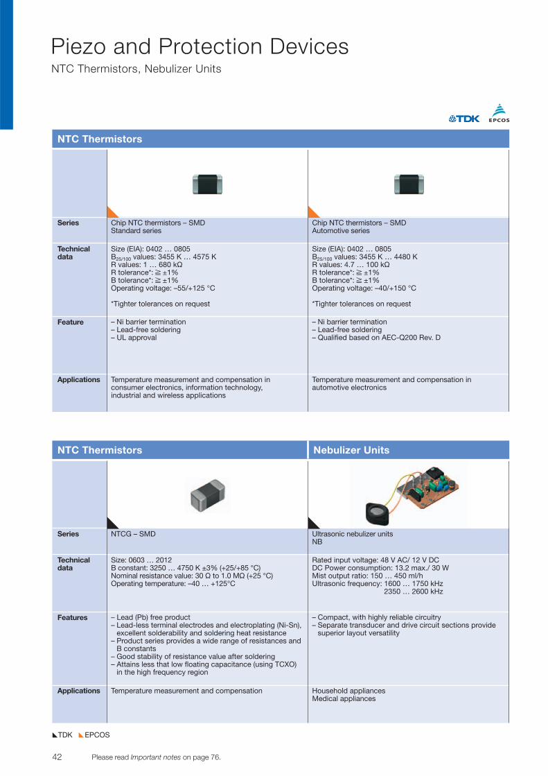
42 Please read Important notes on page 76. © TDK-EPC Corporation 2010
Piezo and Protection DevicesNTC Thermistors, Nebulizer Units
EPCOSTDK
Series Chip NTC thermistors – SMD Chip NTC thermistors – SMDStandard series Automotive series
Technicaldata
Feature
Applications
NTC Thermistors
Size (EIA): 0402 … 0805B25/100 values: 3455 K … 4575 KR values: 1 … 680 kVR tolerance*: ≥ ±1%B tolerance*: ≥ ±1%Operating voltage: –55/+125 °C
*Tighter tolerances on request
– Ni barrier termination– Lead-free soldering– UL approval
– Ni barrier termination– Lead-free soldering– Qualified based on AEC-Q200 Rev. D
Temperature measurement and compensation in consumer electronics, information technology, industrial and wireless applications
Temperature measurement and compensation in automotive electronics
Size (EIA): 0402 … 0805B25/100 values: 3455 K … 4480 KR values: 4.7 … 100 kVR tolerance*: ≥ ±1%B tolerance*: ≥ ±1%Operating voltage: –40/+150 °C
*Tighter tolerances on request
Series NTCG – SMD Ultrasonic nebulizer unitsNB
Technicaldata
Features
Applications
NTC Thermistors Nebulizer Units
Size: 0603 … 2012B constant: 3250 … 4750 K ±3% (+25/+85 °C)Nominal resistance value: 30 V to 1.0 MV (+25 °C)Operating temperature: –40 … +125°C
– Lead (Pb) free product– Lead-less terminal electrodes and electroplating (Ni-Sn),
excellent solderability and soldering heat resistance– Product series provides a wide range of resistances and
B constants– Good stability of resistance value after soldering– Attains less that low floating capacitance (using TCXO)
in the high frequency region
– Compact, with highly reliable circuitry– Separate transducer and drive circuit sections provide
superior layout versatility
Temperature measurement and compensation Household appliancesMedical appliances
Rated input voltage: 48 V AC/ 12 V DCDC Power consumption: 13.2 max./ 30 WMist output ratio: 150 … 450 ml/hUltrasonic frequency: 1600 … 1750 kHz
2350 … 2600 kHz
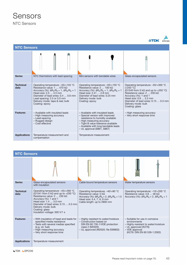
43© TDK-EPC Corporation 2010 Please read Important notes on page 76.
SensorsNTC Sensors
EPCOSTDK
Series NTC thermistors with lead spacing Mini sensors with bendable wires Glass-encapsulated sensors
Technicaldata
Features
Applications
NTC Sensors
Operating temperature: –55/+155 °CResistance value: 1 … 470 kVAccuracy (%): DRR/RR = 1, DRB/RB = 1Head size: 2.5 … 4.5 mmDiameter of lead wires: 0.4 … 0.6 mmLead spacing: 2.5 or 5.0 mmDelivery mode: tape & reel; bulkCoating: epoxy
– Available with insulated leads– High measuring accuracy– Lead-spacing – Rugged design– Cost effective
Operating temperature: –55/+155 °CResistance value: 2 … 100 kVAccuracy (%): DRR/RR = 1, DRB/RB = 1Head size: 2.41 … 2.8 mmDiameter of lead wires: 0.25 mmDelivery mode: bulkCoating: epoxy
– Available with insulated leads– Special version with improved
resistance to humidity available– High measuring accuracy– Tight B value tolerance available– Available with long bendable leads– UL approval (S861, S867)
Operating temperature: –55/+300 °C(+250 °C)(G1540 from 5 kV and up to +250 °C)Resistance value: 2 … 230 kVAccuracy (%): 1 and 1Head size: 0.9 … 2.5 mmDiameter of lead wires: 0.15 … 0.3 mmDelivery mode: bulkCoating: glass
– High measuring accuracy– Very short response time
Temperature measurement and compensation
Temperature measurement
Series Glass-encapsulated sensors Cable-bound temperature sensors Water temperature sensorswith insulation
Technicaldata
Features
Applications
NTC Sensors
Operating temperature: –55/+260 °C (G1541 from 5 kV and up to +250 °C)Resistance value: 2 … 230 kVAccuracy (%): 1 and 1Head size: 1.4 … 3.0 mmDiameter of lead wires: 0.15 … 0.3 mmDelivery mode: bulkCoating: glassInsulation voltage: 500 V/1 s
– With insulation of head and leads forspecified media resistance
– Tests with several medias specified(e.g. oil, fuel)
– High measuring accuracy– Very short response time
Operating temperature: –40/+80 °CResistance value: 5 kVAccuracy (%): DRR/RR = 2, DRB/RB = 1.5Head size: 5.4, 7, 8, 9 mmCable length: up to 2800 mm
– Highly resistant to water/moisture– Construction based on
DIN EN 60 730-1/VDE protectionclass 2 (M2020)
– UL approved (M2020: file E69802)
Operating temperature: –10/+200 °CResistance value: 4.8 … 48 kVAccuracy (%): DRR/RR = 2, DRB/RB = 1
– Suitable for use in corrosive environments
– Highly resistant to water/moisture– UL approved (K276)– VDE approval
(K276: DIN EN 60 539-1:2002)
Temperature measurement
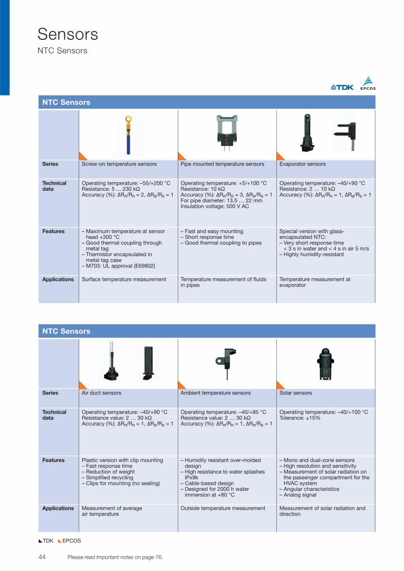
44 Please read Important notes on page 76. © TDK-EPC Corporation 2010
SensorsNTC Sensors
EPCOSTDK
Series Screw-on temperature sensors Pipe mounted temperature sensors Evaporator sensors
Technicaldata
Features
Applications
NTC Sensors
Operating temperature: –55/+200 °CResistance: 5 … 230 kVAccuracy (%): DRR/RR = 2, DRB/RB = 1
– Maximum temperature at sensorhead +300 °C
– Good thermal coupling through metal tag
– Thermistor encapsulated in metal tag case
– M703: UL approval (E69802)
Operating temperature: +5/+100 °CResistance: 10 kVAccuracy (%): DRR/RR = 3, DRB/RB = 1For pipe diameter: 13.5 … 22 mmInsulation voltage: 500 V AC
– Fast and easy mounting– Short response time– Good thermal coupling to pipes
Operating temperature: –40/+90 °CResistance: 2 … 10 kVAccuracy (%): DRR/RR = 1, DRB/RB = 1
Special version with glass -encapsulated NTC:– Very short response time
< 3 s in water and < 4 s in air 5 m/s– Highly humidity-resistant
Surface temperature measurement Temperature measurement of fluids in pipes
Temperature measurement at evaporator
Series Air duct sensors Ambient temperature sensors Solar sensors
Technicaldata
Features
Applications
NTC Sensors
Operating temperature: –40/+90 °CResistance value: 2 … 30 kVAccuracy (%): DRR/RR = 1, DRB/RB = 1
Plastic version with clip mounting– Fast response time– Reduction of weight– Simplified recycling– Clips for mounting (no sealing)
Operating temperature: –40/+85 °CResistance value: 2 … 30 kVAccuracy (%): DRR/RR = 1, DRB/RB = 1
– Humidity resistant over-molded design
– High resistance to water splashesIPx9k
– Cable-based design– Designed for 2000 h water
immersion at +80 °C
Operating temperature: –40/+100 °CTolerance: ±15%
– Mono and dual-zone sensors– High resolution and sensitivity– Measurement of solar radiation on
the passenger compartment for theHVAC system
– Angular characteristics– Analog signal
Measurement of average air temperature
Outside temperature measurement Measurement of solar radiation and direction
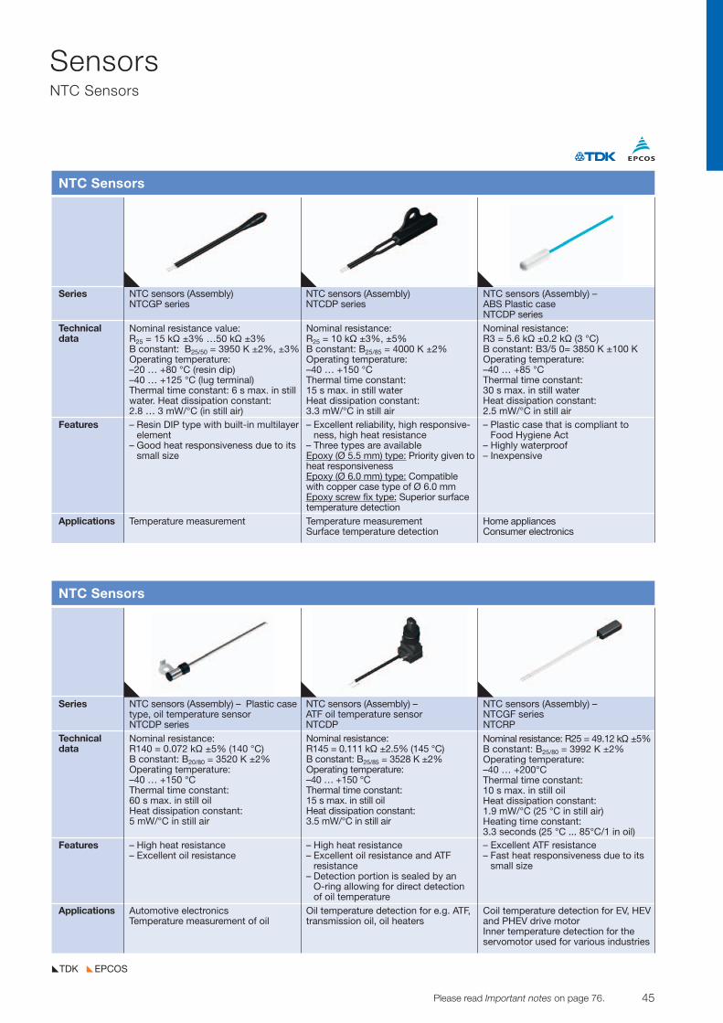
45© TDK-EPC Corporation 2010 Please read Important notes on page 76.
SensorsNTC Sensors
EPCOSTDK
Series NTC sensors (Assembly) – Plastic case NTC sensors (Assembly) – NTC sensors (Assembly) –type, oil temperature sensor ATF oil temperature sensor NTCGF seriesNTCDP series NTCDP NTCRP
Technicaldata
Features
Applications
NTC Sensors
Nominal resistance: R140 = 0.072 kV ±5% (140 °C)B constant: B20/80 = 3520 K ±2%Operating temperature: –40 … +150 °CThermal time constant: 60 s max. in still oilHeat dissipation constant: 5 mW/°C in still air
– High heat resistance– Excellent oil resistance
Nominal resistance: R145 = 0.111 kV ±2.5% (145 °C)B constant: B25/85 = 3528 K ±2%Operating temperature: –40 … +150 °CThermal time constant: 15 s max. in still oilHeat dissipation constant: 3.5 mW/°C in still air
– High heat resistance– Excellent oil resistance and ATF
resistance– Detection portion is sealed by an
O-ring allowing for direct detection of oil temperature
– Excellent ATF resistance– Fast heat responsiveness due to its
small size
Nominal resistance: R25 = 49.12 kV ±5%B constant: B25/80 = 3992 K ±2%Operating temperature: –40 … +200°CThermal time constant: 10 s max. in still oilHeat dissipation constant: 1.9 mW/°C (25 °C in still air)Heating time constant: 3.3 seconds (25 °C ... 85°C/1 in oil)
Automotive electronicsTemperature measurement of oil
Oil temperature detection for e.g. ATF,transmission oil, oil heaters
Coil temperature detection for EV, HEVand PHEV drive motorInner temperature detection for theservomotor used for various industries
Series NTC sensors (Assembly) NTC sensors (Assembly) NTC sensors (Assembly) – NTCGP series NTCDP series ABS Plastic case
NTCDP seriesTechnicaldata
Features
Applications
NTC Sensors
– Resin DIP type with built-in multilayerelement
– Good heat responsiveness due to itssmall size
– Excellent reliability, high responsive-ness, high heat resistance
– Three types are availableEpoxy (Ø 5.5 mm) type: Priority given to heat responsivenessEpoxy (Ø 6.0 mm) type: Compatiblewith copper case type of Ø 6.0 mmEpoxy screw fix type: Superior surface temperature detection
– Plastic case that is compliant toFood Hygiene Act
– Highly waterproof– Inexpensive
Temperature measurement Temperature measurement Surface temperature detection
Home appliancesConsumer electronics
Nominal resistance value: R25 = 15 kV ±3% …50 kV ±3%B constant: B25/50 = 3950 K ±2%, ±3%Operating temperature: –20 … +80 °C (resin dip)–40 … +125 °C (lug terminal)Thermal time constant: 6 s max. in stillwater. Heat dissipation constant: 2.8 … 3 mW/°C (in still air)
Nominal resistance: R25 = 10 kV ±3%, ±5%B constant: B25/85 = 4000 K ±2%Operating temperature: –40 … +150 °CThermal time constant: 15 s max. in still waterHeat dissipation constant: 3.3 mW/°C in still air
Nominal resistance: R3 = 5.6 kV ±0.2 kV (3 °C)B constant: B3/5 0= 3850 K ±100 KOperating temperature: –40 … +85 °CThermal time constant: 30 s max. in still waterHeat dissipation constant: 2.5 mW/°C in still air
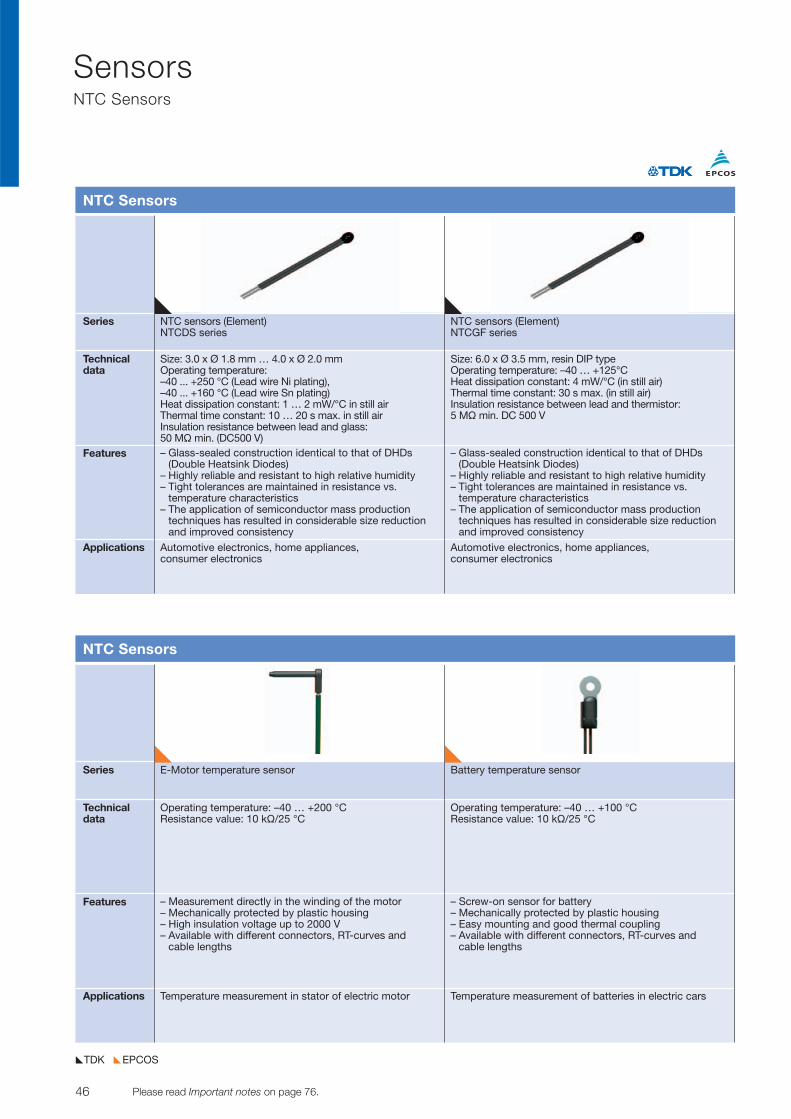
46 Please read Important notes on page 76. © TDK-EPC Corporation 2010
SensorsNTC Sensors
EPCOSTDK
Series NTC sensors (Element) NTC sensors (Element)NTCDS series NTCGF series
Technicaldata
Features
Applications
NTC Sensors
Size: 3.0 x Ø 1.8 mm … 4.0 x Ø 2.0 mmOperating temperature:–40 ... +250 °C (Lead wire Ni plating), –40 ... +160 °C (Lead wire Sn plating)Heat dissipation constant: 1 … 2 mW/°C in still airThermal time constant: 10 … 20 s max. in still airInsulation resistance between lead and glass: 50 MV min. (DC500 V)– Glass-sealed construction identical to that of DHDs
(Double Heatsink Diodes)– Highly reliable and resistant to high relative humidity – Tight tolerances are maintained in resistance vs.
temperature characteristics– The application of semiconductor mass production
techniques has resulted in considerable size reductionand improved consistency
– Glass-sealed construction identical to that of DHDs(Double Heatsink Diodes)
– Highly reliable and resistant to high relative humidity – Tight tolerances are maintained in resistance vs.
temperature characteristics– The application of semiconductor mass production
techniques has resulted in considerable size reductionand improved consistency
Automotive electronics, home appliances, consumer electronics
Automotive electronics, home appliances, consumer electronics
Size: 6.0 x Ø 3.5 mm, resin DIP type Operating temperature: –40 … +125°CHeat dissipation constant: 4 mW/°C (in still air)Thermal time constant: 30 s max. (in still air)Insulation resistance between lead and thermistor: 5 MV min. DC 500 V
Series E-Motor temperature sensor Battery temperature sensor
Technicaldata
Features
Applications
NTC Sensors
Operating temperature: –40 … +200 °CResistance value: 10 kV/25 °C
– Measurement directly in the winding of the motor– Mechanically protected by plastic housing– High insulation voltage up to 2000 V– Available with different connectors, RT-curves and
cable lengths
– Screw-on sensor for battery– Mechanically protected by plastic housing– Easy mounting and good thermal coupling– Available with different connectors, RT-curves and
cable lengths
Temperature measurement in stator of electric motor Temperature measurement of batteries in electric cars
Operating temperature: –40 … +100 °CResistance value: 10 kV/25 °C

47© TDK-EPC Corporation 2010 Please read Important notes on page 76.
SensorsPressure Sensors
EPCOSTDK
Series Sensor dies Sensor diesC33 C39
Technicaldata
Features
Applications
Pressure Sensors
Pressure: 1.2 … 12 barOperating temp.: –40 … +135 °CNon-linearity: typ. 0.2% FSOutput span: typ. 100 mVSize: 1.0 x 1.0 mm
– Available with gold bond pads for high corrosionresistance
– Various pressure ranges available
– Miniaturized design for portable devices– High signal stability
Automotive and consumer applications Consumer applications
Pressure: 1.2 barOperating temp.: –40 … +135 °CNon-linearity: typ. 0.2% FSOutput span: typ. 80 mVSize: 0.65 x 0.65 mm
Series Sensor dies MiniCellC32
Technicaldata
Features
Applications
Pressure Sensors
Pressure: 400 mbar … 40 barOperating temp.: –40 … +135 °CNon-linearity: typ. 0.2% FSOutput span: typ. 120 mVSize: 1.65 x 1.65 mm
– Available for absolute, gauge and back side absolute measurements
– Various features on request as gold bond pads andbackside metallization for soldering
– Single side bond pad layout available
– Differential pressure measurement – Pressure transmitter with high media resistance for
both pressure ports with stainless steel diaphragms
Industrial and automotive applications Industrial and automotive applications
Pressure: 0.5 … 10 barOperating temp.: –40 … +140 °CNon-linearity: typ. ±1.5% FSAnalog ratiometric output or digital signal
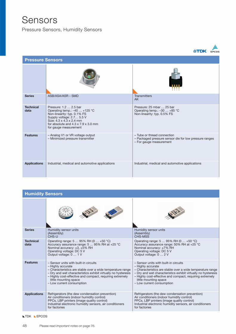
48 Please read Important notes on page 76. © TDK-EPC Corporation 2010
SensorsPressure Sensors, Humidity Sensors
EPCOSTDK
Series ASB/ASA/ASR – SMD TransmittersAK
Technicaldata
Features
Applications
Pressure Sensors
Pressure: 1.2 … 2.5 bar Operating temp.: –40 … +125 °C Non-linearity: typ. 0.1% FS Supply voltage: 2.7… 5.5 VSize: 4.3 x 4.3 x 2.4 mmfor absolute and 4.3 x 7.9 x 3.0 mm for gauge measurement
– Analog V1 or VR voltage output– Minimized pressure transmitter
– Tube or thread connection– Packaged pressure sensor die for low pressure ranges– For gauge measurement
Industrial, medical and automotive applications Industrial, medical and automotive applications
Pressure: 25 mbar … 25 barOperating temp.: –30 … +85 °CNon-linearity: typ. 0.5% FS
Series Humidity sensor units Humidity sensor units(Assembly) (Assembly)CHS-U CHS-MSS
Technicaldata
Features
Applications
Humidity Sensors
Operating range: 5 … 95% RH (0 … +50 °C)Accuracy assurance range: 5 … 95% RH at +25 °CNominal accuracy: ±3, ±5% RHOperating voltage: DC 5 VOutput voltage: 0 … 1 V
– Sensor units with built-in circuits– Highly accurate– Characteristics are stable over a wide temperature range– Dry and wet characteristics exhibit virtually no hysteresis– Highly cost-effective and compact, requiring extremely
little mounting space– Low current consumption
Refrigerators (the dew condensation prevention)Air conditioners (indoor humidity control)PPCs, LBP printers (image quality control)Industrial electronic humidity sensors, air conditioners for factories
Refrigerators (the dew condensation prevention)Air conditioners (indoor humidity control)PPCs, LBP printers (image quality control)Industrial electronic humidity sensors, air conditioners for factories
Operating range: 5 … 95% RH (0 … +50 °C)Accuracy assurance range: 50% RH at +25 °CNominal accuracy: ±7% RHOperating voltage: DC 5 VOutput voltage: 0 … 2 V
– Sensor units with built-in circuits– Highly accurate– Characteristics are stable over a wide temperature range– Dry and wet characteristics exhibit virtually no hysteresis– Highly cost-effective and compact, requiring extremely
little mounting space– Low current consumption
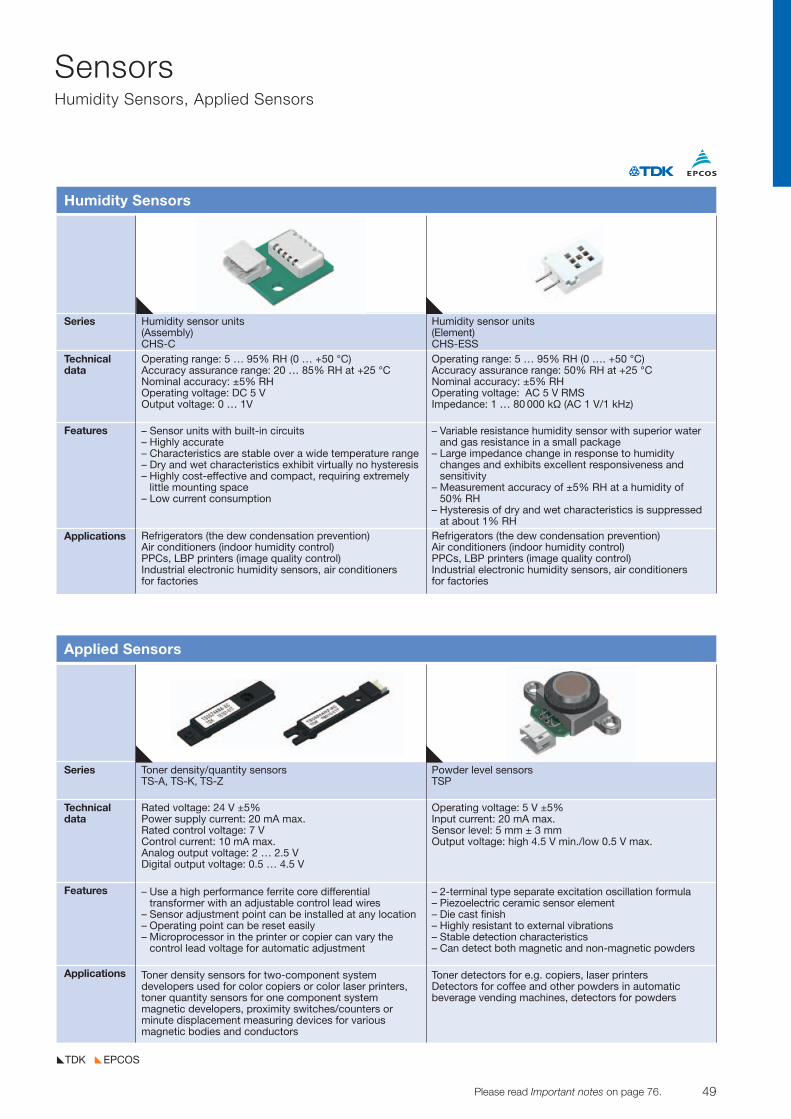
49© TDK-EPC Corporation 2010 Please read Important notes on page 76.
SensorsHumidity Sensors, Applied Sensors
EPCOSTDK
Series Humidity sensor units Humidity sensor units(Assembly) (Element)CHS-C CHS-ESS
Technicaldata
Features
Applications
Humidity Sensors
Operating range: 5 … 95% RH (0 … +50 °C)Accuracy assurance range: 20 … 85% RH at +25 °CNominal accuracy: ±5% RHOperating voltage: DC 5 VOutput voltage: 0 … 1V
– Sensor units with built-in circuits– Highly accurate– Characteristics are stable over a wide temperature range– Dry and wet characteristics exhibit virtually no hysteresis– Highly cost-effective and compact, requiring extremely
little mounting space– Low current consumption
Refrigerators (the dew condensation prevention)Air conditioners (indoor humidity control)PPCs, LBP printers (image quality control)Industrial electronic humidity sensors, air conditioners for factories
Refrigerators (the dew condensation prevention)Air conditioners (indoor humidity control)PPCs, LBP printers (image quality control)Industrial electronic humidity sensors, air conditioners for factories
Operating range: 5 … 95% RH (0 …. +50 °C)Accuracy assurance range: 50% RH at +25 °CNominal accuracy: ±5% RHOperating voltage: AC 5 V RMSImpedance: 1 … 80 000 kV (AC 1 V/1 kHz)
– Variable resistance humidity sensor with superior waterand gas resistance in a small package
– Large impedance change in response to humiditychanges and exhibits excellent responsiveness and sensitivity
– Measurement accuracy of ±5% RH at a humidity of 50% RH
– Hysteresis of dry and wet characteristics is suppressed at about 1% RH
Series Toner density/quantity sensors Powder level sensorsTS-A, TS-K, TS-Z TSP
Technicaldata
Features
Applications
Applied Sensors
Rated voltage: 24 V ±5%Power supply current: 20 mA max. Rated control voltage: 7 VControl current: 10 mA max. Analog output voltage: 2 … 2.5 V Digital output voltage: 0.5 … 4.5 V
– Use a high performance ferrite core differential transformer with an adjustable control lead wires
– Sensor adjustment point can be installed at any location– Operating point can be reset easily– Microprocessor in the printer or copier can vary the
control lead voltage for automatic adjustment
Toner density sensors for two-component system developers used for color copiers or color laser printers,toner quantity sensors for one component system magnetic developers, proximity switches/counters orminute displacement measuring devices for various magnetic bodies and conductors
Operating voltage: 5 V ±5%Input current: 20 mA max.Sensor level: 5 mm ± 3 mmOutput voltage: high 4.5 V min./low 0.5 V max.
– 2-terminal type separate excitation oscillation formula– Piezoelectric ceramic sensor element– Die cast finish– Highly resistant to external vibrations– Stable detection characteristics– Can detect both magnetic and non-magnetic powders
Toner detectors for e.g. copiers, laser printersDetectors for coffee and other powders in automatic beverage vending machines, detectors for powders
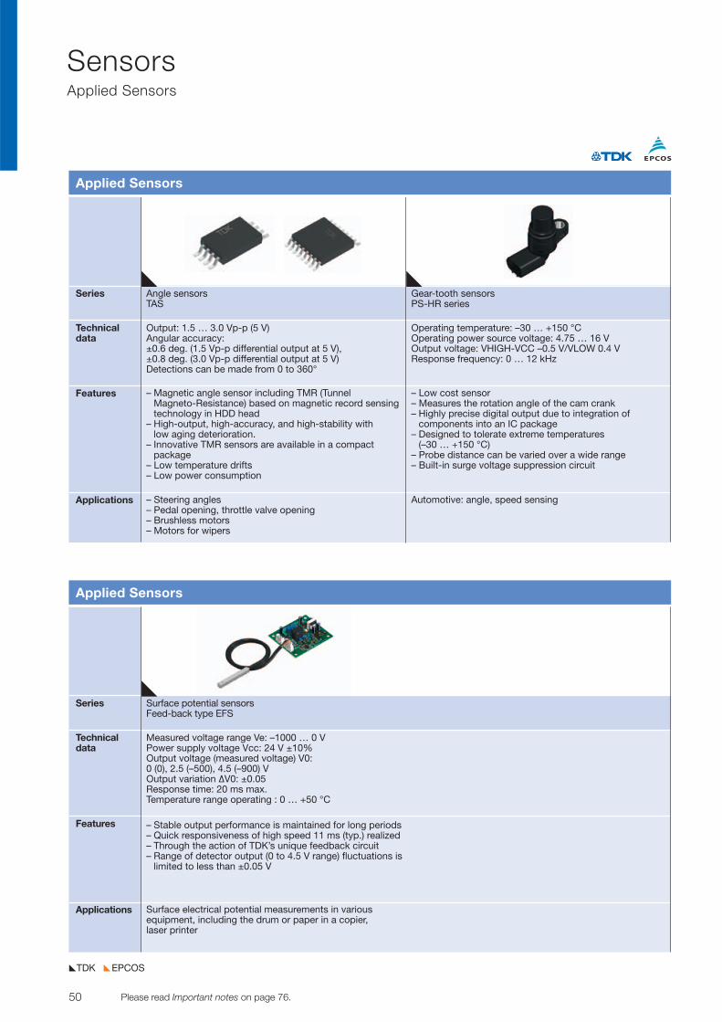
50 Please read Important notes on page 76. © TDK-EPC Corporation 2010
SensorsApplied Sensors
EPCOSTDK
Series Surface potential sensorsFeed-back type EFS
Technicaldata
Features
Applications
Applied Sensors
Measured voltage range Ve: –1000 … 0 VPower supply voltage Vcc: 24 V ±10% Output voltage (measured voltage) V0:0 (0), 2.5 (–500), 4.5 (–900) VOutput variation DV0: ±0.05Response time: 20 ms max. Temperature range operating : 0 … +50 °C
– Stable output performance is maintained for long periods– Quick responsiveness of high speed 11 ms (typ.) realized– Through the action of TDK’s unique feedback circuit– Range of detector output (0 to 4.5 V range) fluctuations is
limited to less than ±0.05 V
Surface electrical potential measurements in variousequipment, including the drum or paper in a copier, laser printer
Series Angle sensors Gear-tooth sensorsTAS PS-HR series
Technicaldata
Features
Applications
Applied Sensors
Output: 1.5 … 3.0 Vp-p (5 V)Angular accuracy: ±0.6 deg. (1.5 Vp-p differential output at 5 V), ±0.8 deg. (3.0 Vp-p differential output at 5 V)Detections can be made from 0 to 360°
– Magnetic angle sensor including TMR (Tunnel Magneto-Resistance) based on magnetic record sensingtechnology in HDD head
– High-output, high-accuracy, and high-stability with low aging deterioration.
– Innovative TMR sensors are available in a compact package
– Low temperature drifts– Low power consumption
– Steering angles– Pedal opening, throttle valve opening– Brushless motors– Motors for wipers
Operating temperature: –30 … +150 °C Operating power source voltage: 4.75 … 16 VOutput voltage: VHIGH-VCC –0.5 V/VLOW 0.4 V Response frequency: 0 … 12 kHz
– Low cost sensor– Measures the rotation angle of the cam crank– Highly precise digital output due to integration of
components into an IC package– Designed to tolerate extreme temperatures
(–30 … +150 °C)– Probe distance can be varied over a wide range– Built-in surge voltage suppression circuit
Automotive: angle, speed sensing
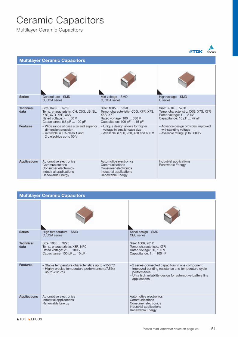
51© TDK-EPC Corporation 2010 Please read Important notes on page 76.
Ceramic CapacitorsMultilayer Ceramic Capacitors
EPCOSTDK
Series General use – SMD Mid voltage – SMD High voltage – SMDC, CGA series C, CGA series C series
Technicaldata
Features
Applications
Multilayer Ceramic Capacitors
Size: 0402 … 5750Temp. characteristic: CH, C0G, JB, SL,X7S, X7R, X5R, X6SRated voltage: 4 … 50 VCapacitance: 0.5 pF … 100 µF– Wide range of case size and superior
dimension precision– Available in EIA class 1 and
2 dielectrics up to 50 V
Size: 1005 … 5750Temp. characteristic: C0G, X7R, X7S,X6S, X7TRated voltage: 100 … 630 VCapacitance: 100 pF … 15 µF– Unique design allows for higher
voltage in smaller case size– Available in 100, 250, 450 and 630 V
Size: 3216 … 5750Temp. characteristic: C0G, X7S, X7RRated voltage: 1 … 3 kV Capacitance: 10 pF … 47 nF
– Advance design provides improvedwithstanding voltage
– Available rating up to 3000 V
Automotive electronicsCommunicationsConsumer electronicsIndustrial applicationsRenewable Energy
Automotive electronicsCommunicationsConsumer electronicsIndustrial applicationsRenewable Energy
Industrial applicationsRenewable Energy
Series High temperature – SMD Serial design – SMDC, CGA series CEU series
Technicaldata
Features
Applications
Multilayer Ceramic Capacitors
Size: 1005 … 3225Temp. characteristic: X8R, NP0 Rated voltage: 25 … 100 VCapacitance: 100 pF … 10 µF
– Stable temperature characteristics up to +150 ºC– Highly precise temperature performance (±7.5%)
up to +125 ºC
Automotive electronicsIndustrial applicationsRenewable Energy
Automotive electronicsCommunicationsConsumer electronicsIndustrial applicationsRenewable Energy
Size: 1608, 2012Temp. characteristic: X7RRated voltage: 50, 100 VCapacitance: 1 … 100 nF
– 2 series-connected capacitors in one component– Improved bending resistance and temperature cycle
performance– Ultra high reliability design for automotive battery line
applications
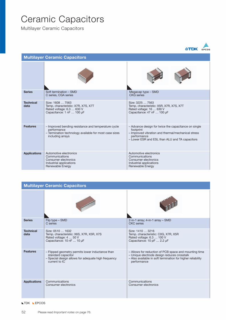
52 Please read Important notes on page 76. © TDK-EPC Corporation 2010
Ceramic CapacitorsMultilayer Ceramic Capacitors
EPCOSTDK
Series Soft termination – SMD Megacap type – SMDC series, CGA series CKG series
Technicaldata
Features
Applications
Multilayer Ceramic Capacitors
Size: 1608 … 7563Temp. characteristic: X7R, X7S, X7TRated voltage: 6.3 … 630 VCapacitance: 1 nF … 100 µF
– Improved bending resistance and temperature cycle performance
– Termination technology available for most case sizes including arrays
Automotive electronicsCommunicationsConsumer electronicsIndustrial applicationsRenewable Energy
Size: 3225 … 7563Temp. characteristic: X5R, X7R, X7S, X7TRated voltage: 16 … 630 V Capacitance: 47 nF … 100 µF
– Advance design for twice the capacitance on single footprint
– Improved vibration and thermal/mechanical stress performance
– Lower ESR and ESL than ALU and TA capacitors
Automotive electronicsCommunicationsConsumer electronicsIndustrial applicationsRenewable Energy
Series Flip type – SMD 2-in-1 array; 4-in-1 array – SMDC series CKC series
Technicaldata
Features
Applications
Multilayer Ceramic Capacitors
Size: 0510 … 1632Temp. characteristic: X6S, X7R, X5R, X7SRated voltage: 4 … 50 VCapacitance: 10 nF … 10 µF
– Flipped geometry permits lower inductance than standard capacitor
– Special design allows for adequate high frequency current to IC
CommunicationsConsumer electronics
CommunicationsConsumer electronics
Size: 1410 … 3216Temp. characteristic: C0G, X7R, X5RRated voltage: 6.3 … 100 V Capacitance: 10 pF … 2.2 µF
– Allows for reduction of PCB space and mounting time– Unique electrode design reduces crosstalk– Also available in soft termination for higher reliability
performance
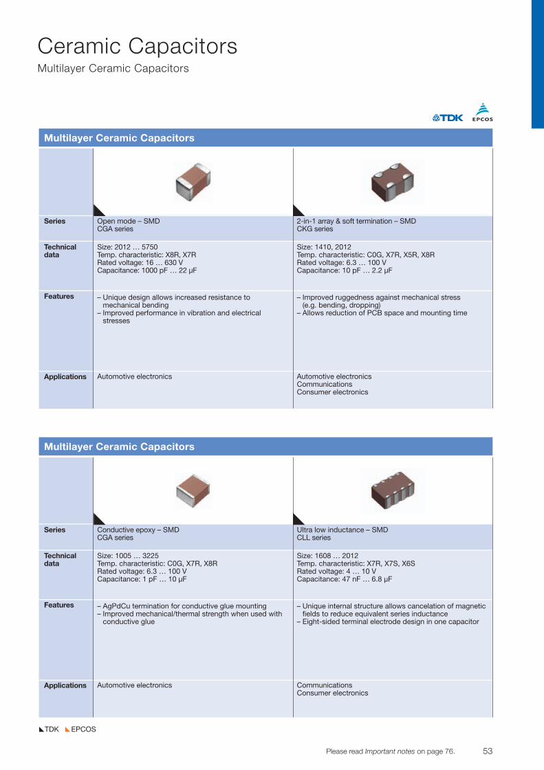
53© TDK-EPC Corporation 2010 Please read Important notes on page 76.
Ceramic CapacitorsMultilayer Ceramic Capacitors
EPCOSTDK
Series Conductive epoxy – SMD Ultra low inductance – SMDCGA series CLL series
Technicaldata
Features
Applications
Multilayer Ceramic Capacitors
Size: 1005 … 3225Temp. characteristic: C0G, X7R, X8RRated voltage: 6.3 … 100 V Capacitance: 1 pF … 10 µF
– AgPdCu termination for conductive glue mounting– Improved mechanical/thermal strength when used with
conductive glue
Automotive electronics CommunicationsConsumer electronics
Size: 1608 … 2012Temp. characteristic: X7R, X7S, X6SRated voltage: 4 … 10 VCapacitance: 47 nF … 6.8 µF
– Unique internal structure allows cancelation of magneticfields to reduce equivalent series inductance
– Eight-sided terminal electrode design in one capacitor
Series Open mode – SMD 2-in-1 array & soft termination – SMDCGA series CKG series
Technicaldata
Features
Applications
Multilayer Ceramic Capacitors
Size: 2012 … 5750Temp. characteristic: X8R, X7RRated voltage: 16 … 630 V Capacitance: 1000 pF … 22 µF
– Unique design allows increased resistance to mechanical bending
– Improved performance in vibration and electrical stresses
Automotive electronics Automotive electronicsCommunicationsConsumer electronics
Size: 1410, 2012Temp. characteristic: C0G, X7R, X5R, X8RRated voltage: 6.3 … 100 V Capacitance: 10 pF … 2.2 µF
– Improved ruggedness against mechanical stress (e.g. bending, dropping)
– Allows reduction of PCB space and mounting time
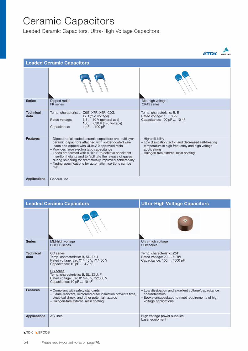
54 Please read Important notes on page 76. © TDK-EPC Corporation 2010
Ceramic CapacitorsLeaded Ceramic Capacitors, Ultra-High Voltage Capacitors
EPCOSTDK
Series Dipped radial Mid-high voltageFK series CK45 series
Technicaldata
Features
Applications
Leaded Ceramic Capacitors
Temp. characteristic: C0G, X7R, X5R, C0G, X7R (mid voltage)
Rated voltage: 6.3 … 50 V (general use) 100 … 630 V (mid voltage)
Capacitance: 1 pF … 100 µF
– Dipped radial leaded ceramic capacitors are multilayer ceramic capacitors attached with solder coated wireleads and dipped with UL94V-0 approved resin
– Provides large electrostatic capacitance– Leads are formed with a “kink” to achieve consistent
insertion heights and to facilitate the release of gasesduring soldering for dramatically improved solderability
– Taping specifications for automatic insertions can bemet
General use
Temp. characteristic: B, ERated voltage: 1 … 3 kVCapacitance: 100 pF … 10 nF
– High reliability– Low dissipation factor, and decreased self-heating
temperature in high frequency and high voltage applications
– Halogen-free external resin coating
Series Mid-high voltage Ultra-high voltageCD/ CS series UHV series
Technicaldata
Features
Applications
Leaded Ceramic Capacitors Ultra-High Voltage Capacitors
CD seriesTemp. characteristic: B, SL, Z5U Rated voltage: Eac X1/440 V, Y1/400 V Capacitance: 10 pF … 4.7 nF
CS seriesTemp. characteristic: B, SL, Z5U, F Rated voltage: Eac X1/440 V, Y2/300 V Capacitance: 10 pF … 10 nF
– Compliant with safety standards – Flame-resistant, reinforced outer insulation prevents fires,
electrical shock, and other potential hazards– Halogen-free external resin coating
AC lines High voltage power suppliesLaser equipment
Temp. characteristic: Z5TRated voltage: 20 … 50 kVCapacitance: 100 … 4000 pF
– Low dissipation and excellent voltage/capacitance characteristics
– Epoxy-encapsulated to meet requirements of high voltage applications
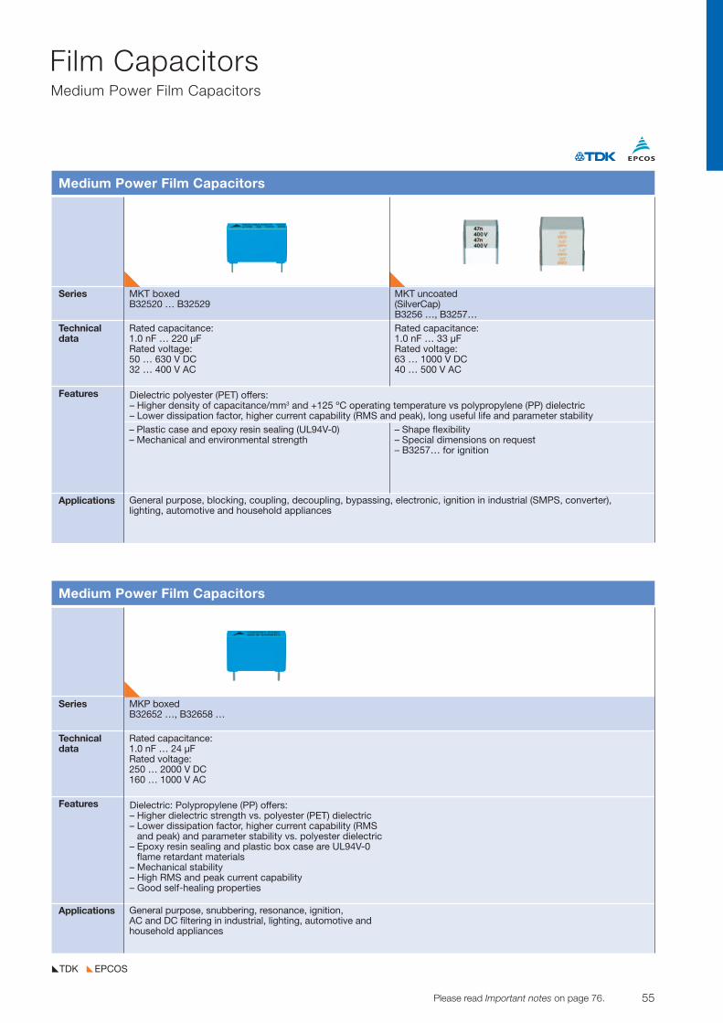
55© TDK-EPC Corporation 2010 Please read Important notes on page 76.
Film CapacitorsMedium Power Film Capacitors
EPCOSTDK
Series MKT boxed MKT uncoatedB32520 … B32529 (SilverCap)
B3256 …, B3257…Technicaldata
Features
Applications
Medium Power Film Capacitors
Rated capacitance:1.0 nF … 220 µFRated voltage: 50 … 630 V DC32 … 400 V AC
– Plastic case and epoxy resin sealing (UL94V-0)– Mechanical and environmental strength
General purpose, blocking, coupling, decoupling, bypassing, electronic, ignition in industrial (SMPS, converter),lighting, automotive and household appliances
Rated capacitance: 1.0 nF … 33 µFRated voltage: 63 … 1000 V DC40 … 500 V AC
– Shape flexibility– Special dimensions on request– B3257… for ignition
Dielectric polyester (PET) offers: – Higher density of capacitance/mm3 and +125 ºC operating temperature vs polypropylene (PP) dielectric– Lower dissipation factor, higher current capability (RMS and peak), long useful life and parameter stability
Series MKP boxedB32652 …, B32658 …
Technicaldata
Features
Applications
Medium Power Film Capacitors
Rated capacitance:1.0 nF … 24 µFRated voltage:250 … 2000 V DC160 … 1000 V AC
General purpose, snubbering, resonance, ignition, AC and DC filtering in industrial, lighting, automotive andhousehold appliances
Dielectric: Polypropylene (PP) offers: – Higher dielectric strength vs. polyester (PET) dielectric– Lower dissipation factor, higher current capability (RMS
and peak) and para meter stability vs. polyester dielectric– Epoxy resin sealing and plastic box case are UL94V-0
flame retardant materials– Mechanical stability– High RMS and peak current capability– Good self-healing properties
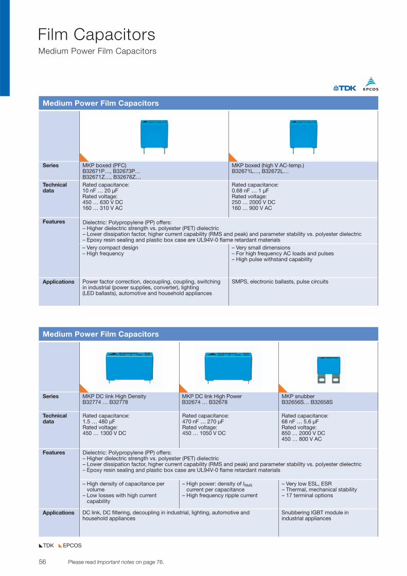
56 Please read Important notes on page 76. © TDK-EPC Corporation 2010
Film CapacitorsMedium Power Film Capacitors
EPCOSTDK
Series MKP boxed (PFC) MKP boxed (high V AC-temp.)B32671P…, B32673P… B32671L…, B32672L…B32671Z…, B32676Z…
Technicaldata
Features
Applications
Medium Power Film Capacitors
Rated capacitance:10 nF … 20 µFRated voltage:450 … 630 V DC160 … 310 V AC
– Very compact design– High frequency
Power factor correction, decoupling, coupling, switching in industrial (power supplies, converter), lighting (LED ballasts), automotive and household appliances
SMPS, electronic ballasts, pulse circuits
Rated capacitance:0.68 nF … 1 µFRated voltage:250 … 2000 V DC160 … 900 V AC
– Very small dimensions– For high frequency AC loads and pulses– High pulse withstand capability
Dielectric: Polypropylene (PP) offers: – Higher dielectric strength vs. polyester (PET) dielectric– Lower dissipation factor, higher current capability (RMS and peak) and parameter stability vs. polyester dielectric– Epoxy resin sealing and plastic box case are UL94V-0 flame retardant materials
Series MKP DC link High Density MKP DC link High Power MKP snubberB32774 … B32778 B32674 … B32678 B32656S… B32658S
Technicaldata
Features
Applications
Medium Power Film Capacitors
Rated capacitance:68 nF … 5.6 µFRated voltage:850 … 2000 V DC450 … 800 V AC
Dielectric: Polypropylene (PP) offers: – Higher dielectric strength vs. polyester (PET) dielectric– Lower dissipation factor, higher current capability (RMS and peak) and parameter stability vs. polyester dielectric– Epoxy resin sealing and plastic box case are UL94V-0 flame retardant materials
Rated capacitance:1.5 … 480 µFRated voltage:450 … 1300 V DC
Rated capacitance:470 nF … 270 µFRated voltage:450 … 1050 V DC
DC link, DC filtering, decoupling in industrial, lighting, automotive and household appliances
Snubbering IGBT module inindustrial appliances
– High density of capacitance per volume
– Low losses with high current capability
– High power: density of IRMScurrent per capacitance
– High frequency ripple current
– Very low ESL, ESR– Thermal, mechanical stability– 17 terminal options
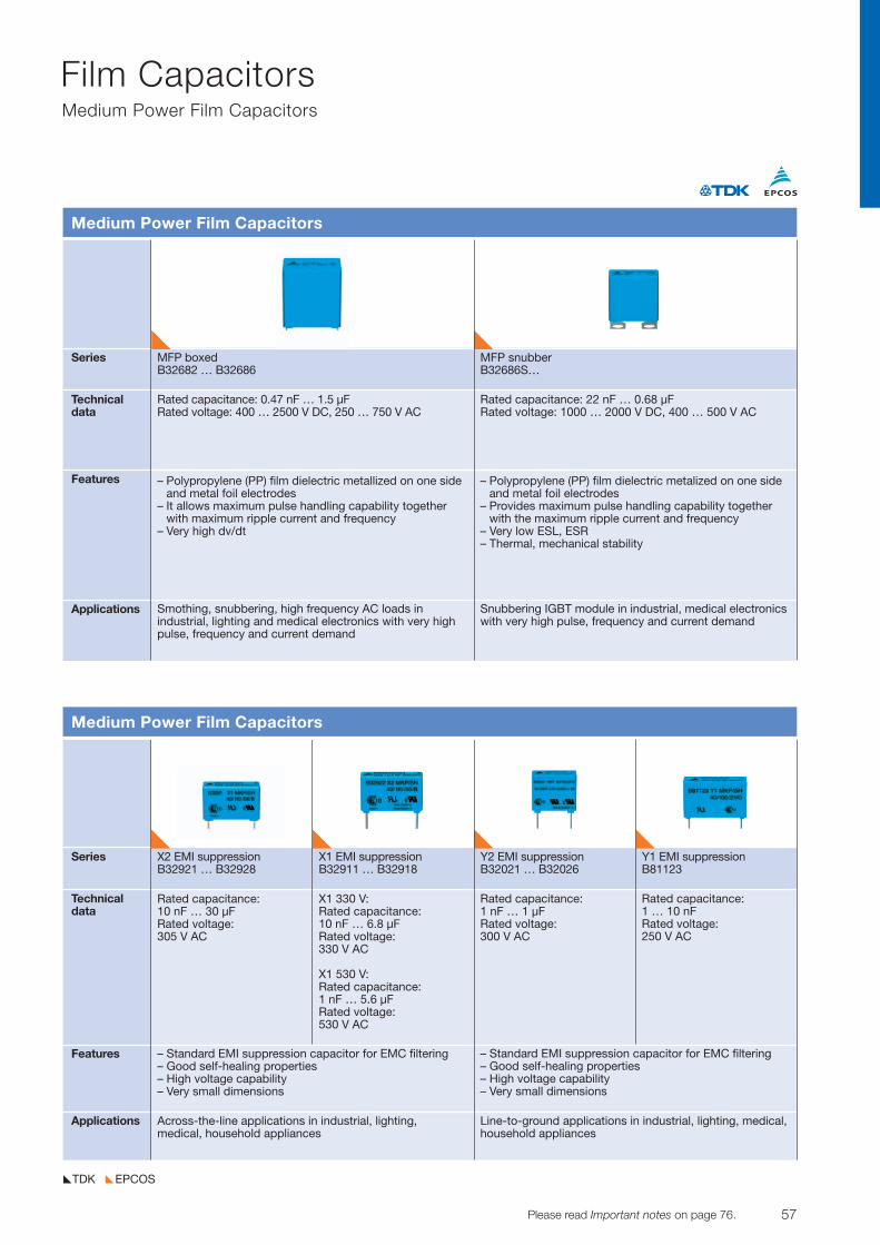
57© TDK-EPC Corporation 2010 Please read Important notes on page 76.
Film CapacitorsMedium Power Film Capacitors
EPCOSTDK
Series X2 EMI suppression X1 EMI suppression Y2 EMI suppression Y1 EMI suppressionB32921 … B32928 B32911 … B32918 B32021 … B32026 B81123
Technical data
Features
Applications
Medium Power Film Capacitors
Rated capacitance: 10 nF … 30 µFRated voltage: 305 V AC
– Standard EMI suppression capacitor for EMC filtering– Good self-healing properties– High voltage capability– Very small dimensions
X1 330 V:Rated capacitance: 10 nF … 6.8 µFRated voltage: 330 V AC
X1 530 V: Rated capacitance: 1 nF … 5.6 µFRated voltage: 530 V AC
Rated capacitance: 1 nF … 1 µFRated voltage: 300 V AC
– Standard EMI suppression capacitor for EMC filtering– Good self-healing properties– High voltage capability– Very small dimensions
Rated capacitance: 1 … 10 nFRated voltage: 250 V AC
Across-the-line applications in industrial, lighting, medical, household appliances
Line-to-ground applications in industrial, lighting, medical,household appliances
Series MFP boxed MFP snubberB32682 … B32686 B32686S…
Technicaldata
Features
Applications
Medium Power Film Capacitors
Rated capacitance: 0.47 nF … 1.5 µFRated voltage: 400 … 2500 V DC, 250 … 750 V AC
– Polypropylene (PP) film dielectric metallized on one sideand metal foil electrodes
– It allows maximum pulse handling capability togetherwith maximum ripple current and frequency
– Very high dv/dt
Smothing, snubbering, high frequency AC loads in industrial, lighting and medical electronics with very highpulse, frequency and current demand
Snubbering IGBT module in industrial, medical electronicswith very high pulse, frequency and current demand
Rated capacitance: 22 nF … 0.68 µFRated voltage: 1000 … 2000 V DC, 400 … 500 V AC
– Polypropylene (PP) film dielectric metalized on one sideand metal foil electrodes
– Provides maximum pulse handling capability togetherwith the maximum ripple current and frequency
– Very low ESL, ESR– Thermal, mechanical stability
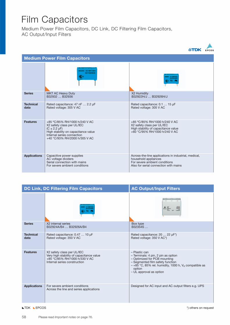
58 Please read Important notes on page 76. © TDK-EPC Corporation 2010
Film Capacitors Medium Power Film Capacitors, DC Link, DC Filtering Film Capacitors, AC Output/Input Filters
EPCOSTDK *) others on request
Series MKT AC Heavy Duty X2 HumidityB32932 … B32936 B32922H/J … B32926H/J
Technicaldata
Features
Applications
Medium Power Film Capacitors
Rated capacitance: 47 nF … 2.2 µFRated voltage: 305 V AC
+85 ºC/85% RH/1000 h/240 V ACX2 safety class per UL/IEC(C ≤ 2.2 µF)High stability on capacitance valueInternal series connection+40 °C/93% RH/2000 h/305 V AC
Capacitive power suppliesAC voltage dividersSerial connection with mainsFor severe ambient conditions
Rated capacitance: 0.1 … 15 µFRated voltage: 305 V AC
+85 ºC/85% RH/1000 h/240 V ACX2 safety class per UL/IEC High stability of capacitance value+60 °C/95% RH/1000 h/240 V AC
Across-the-line applications in industrial, medical, household appliances For severe ambient conditionsAlso for serial connection with mains
Series X2 internal series Box typeB32924A/B4 … B32926A/B4 B32354S …
Technicaldata
Features
Applications
DC Link, DC Filtering Film Capacitors AC Output/Input Filters
Rated capacitance: 0.47 … 10 µFRated voltage: 350 V AC
X2 safety class per UL/IECVery high stability of capacitance value+85 °C/85% RH/1000 h/330 V ACInternal series construction
For severe ambient conditionsAcross the line and series applications
Rated capacitance: 20 … 22 µF*) Rated voltage: 350 V AC*)
– Plastic can– Terminals: 4 pin, 2 pin as option– Optimized for PCB mounting– Segmented film safety function – +85 °C, 85% rel. humidity, 1000 h, VR compatible as
option – UL approval as option
Designed for AC input and AC output filters e.g. UPS
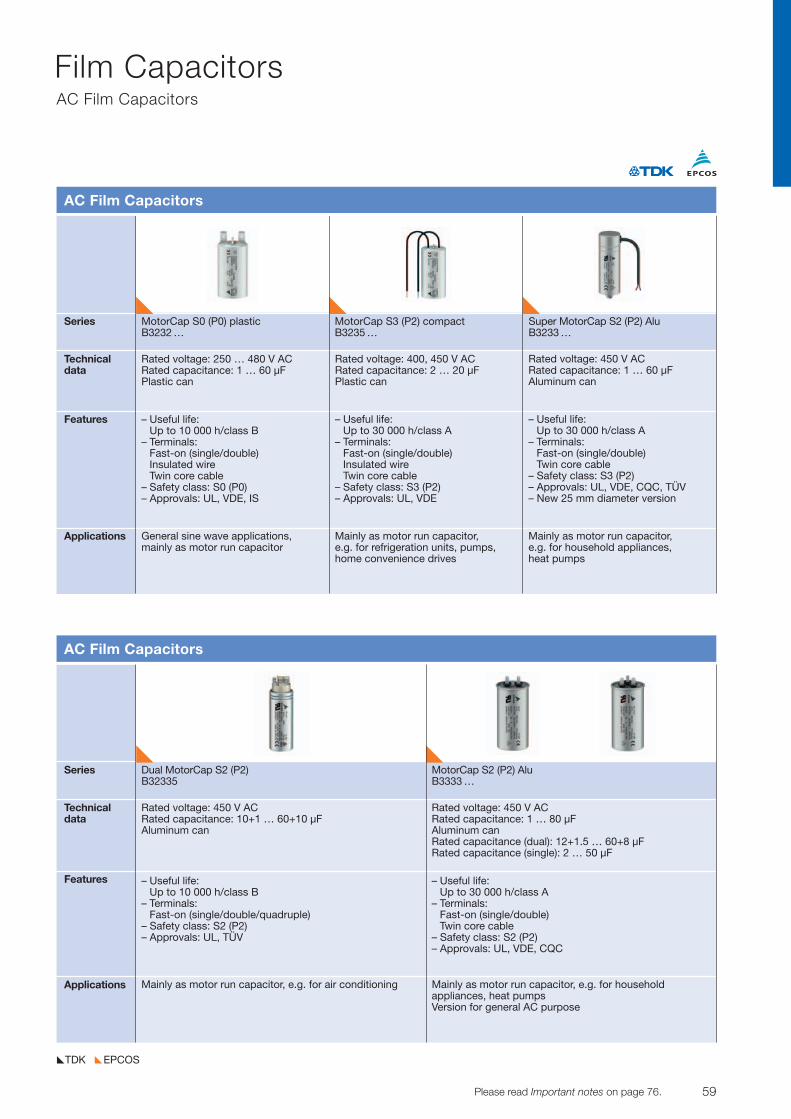
59© TDK-EPC Corporation 2010 Please read Important notes on page 76.
Film CapacitorsAC Film Capacitors
EPCOSTDK
Series MotorCap S0 (P0) plastic MotorCap S3 (P2) compact Super MotorCap S2 (P2) AluB3232 … B3235 … B3233 …
Technicaldata
Features
Applications
AC Film Capacitors
Rated voltage: 250 … 480 V ACRated capacitance: 1 … 60 µFPlastic can
– Useful life: Up to 10 000 h/class B
– Terminals: Fast-on (single/double)Insulated wire Twin core cable
– Safety class: S0 (P0)– Approvals: UL, VDE, IS
Rated voltage: 400, 450 V ACRated capacitance: 2 … 20 µFPlastic can
– Useful life:Up to 30 000 h/class A
– Terminals:Fast-on (single/double)Insulated wireTwin core cable
– Safety class: S3 (P2)– Approvals: UL, VDE
Rated voltage: 450 V ACRated capacitance: 1 … 60 µFAluminum can
– Useful life:Up to 30 000 h/class A
– Terminals:Fast-on (single/double)Twin core cable
– Safety class: S3 (P2)– Approvals: UL, VDE, CQC, TÜV– New 25 mm diameter version
General sine wave applications, mainly as motor run capacitor
Mainly as motor run capacitor, e.g. for refrigeration units, pumps,home convenience drives
Mainly as motor run capacitor, e.g. for household appliances, heat pumps
Series Dual MotorCap S2 (P2) MotorCap S2 (P2) AluB32335 B3333 …
Technicaldata
Features
Applications
AC Film Capacitors
Rated voltage: 450 V ACRated capacitance: 10+1 … 60+10 µFAluminum can
– Useful life:Up to 10 000 h/class B
– Terminals:Fast-on (single/double/quadruple)
– Safety class: S2 (P2)– Approvals: UL, TÜV
Mainly as motor run capacitor, e.g. for air conditioning Mainly as motor run capacitor, e.g. for household appliances, heat pumpsVersion for general AC purpose
Rated voltage: 450 V ACRated capacitance: 1 … 80 µFAluminum canRated capacitance (dual): 12+1.5 … 60+8 µFRated capacitance (single): 2 … 50 µF
– Useful life: Up to 30 000 h/class A
– Terminals: Fast-on (single/double)Twin core cable
– Safety class: S2 (P2)– Approvals: UL, VDE, CQC
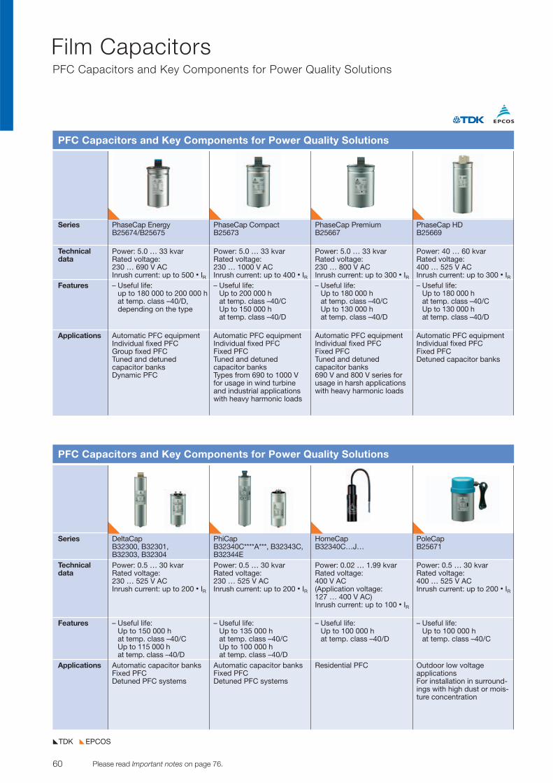
60 Please read Important notes on page 76. © TDK-EPC Corporation 2010
Film CapacitorsPFC Capacitors and Key Components for Power Quality Solutions
EPCOSTDK
Series PhaseCap Energy PhaseCap Compact PhaseCap Premium PhaseCap HDB25674/B25675 B25673 B25667 B25669
Technicaldata
Features
Applications
PFC Capacitors and Key Components for Power Quality Solutions
Power: 5.0 … 33 kvarRated voltage: 230 … 690 V ACInrush current: up to 500 • IR– Useful life:
up to 180 000 to 200 000 h at temp. class –40/D, depending on the type
Power: 5.0 … 33 kvarRated voltage: 230 … 1000 V ACInrush current: up to 400 • IR– Useful life:
Up to 200 000 hat temp. class –40/CUp to 150 000 h at temp. class –40/D
Power: 5.0 … 33 kvarRated voltage: 230 … 800 V ACInrush current: up to 300 • IR– Useful life:
Up to 180 000 h at temp. class –40/CUp to 130 000 h at temp. class –40/D
Power: 40 … 60 kvarRated voltage: 400 … 525 V ACInrush current: up to 300 • IR– Useful life:
Up to 180 000 h at temp. class –40/CUp to 130 000 h at temp. class –40/D
Automatic PFC equipmentIndividual fixed PFC Group fixed PFC Tuned and detuned capacitor banks Dynamic PFC
Automatic PFC equipmentIndividual fixed PFCFixed PFCDetuned capacitor banks
Automatic PFC equipmentIndividual fixed PFCFixed PFCTuned and detuned capacitor banksTypes from 690 to 1000 V for usage in wind turbine and industrial applicationswith heavy harmonic loads
Automatic PFC equipment Individual fixed PFCFixed PFCTuned and detuned capacitor banks690 V and 800 V series forusage in harsh applicationswith heavy harmonic loads
Series DeltaCap PhiCap HomeCap PoleCapB32300, B32301, B32340C****A***, B32343C, B32340C…J… B25671B32303, B32304 B32344E
Technicaldata
Features
Applications
PFC Capacitors and Key Components for Power Quality Solutions
Power: 0.5 … 30 kvarRated voltage: 230 … 525 V ACInrush current: up to 200 • IR
– Useful life: Up to 150 000 h at temp. class –40/CUp to 115 000 h at temp. class –40/D
Power: 0.5 … 30 kvarRated voltage: 230 … 525 V ACInrush current: up to 200 • IR
– Useful life:Up to 135 000 h at temp. class –40/CUp to 100 000 h at temp. class –40/D
Power: 0.02 … 1.99 kvarRated voltage: 400 V AC(Application voltage: 127 … 400 V AC)Inrush current: up to 100 • IR
– Useful life: Up to 100 000 h at temp. class –40/D
Power: 0.5 … 30 kvarRated voltage: 400 … 525 V ACInrush current: up to 200 • IR
– Useful life: Up to 100 000 h at temp. class –40/C
Automatic capacitor banksFixed PFCDetuned PFC systems
Outdoor low voltage applicationsFor installation in surround-ings with high dust or mois-ture concentration
Automatic capacitor banksFixed PFCDetuned PFC systems
Residential PFC
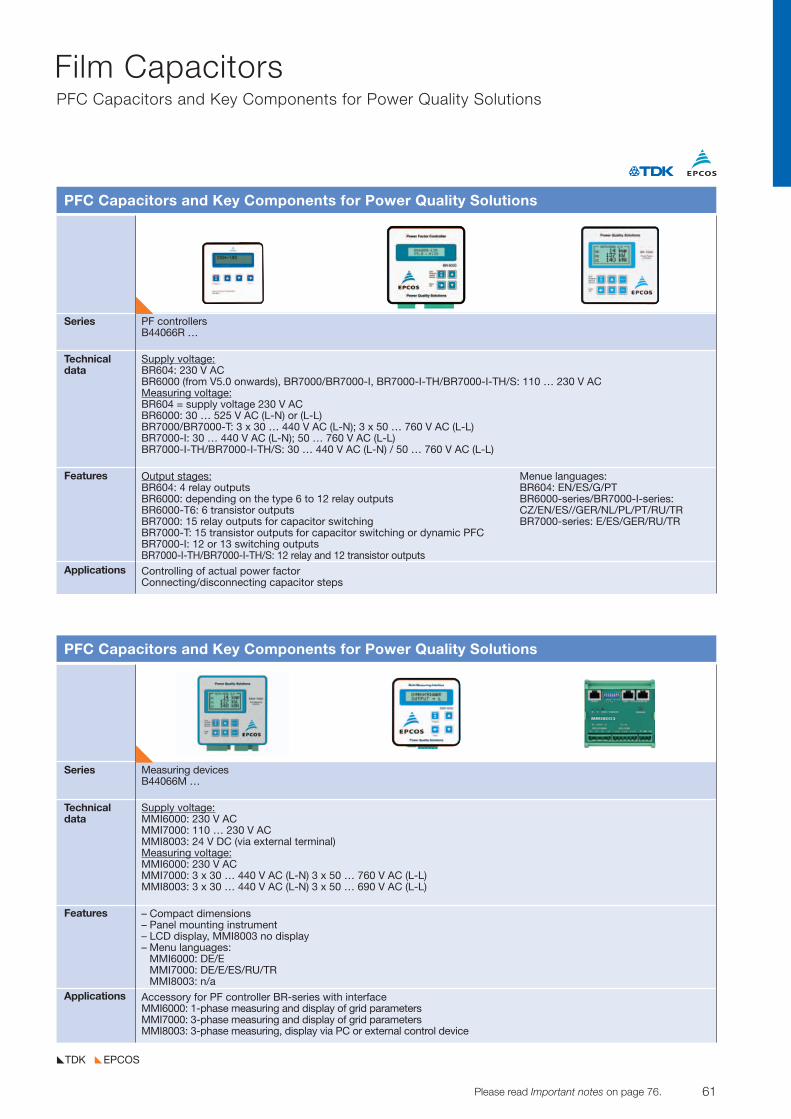
61© TDK-EPC Corporation 2010 Please read Important notes on page 76.
Film CapacitorsPFC Capacitors and Key Components for Power Quality Solutions
EPCOSTDK
Series PF controllersB44066R …
Technicaldata
Features
Applications
PFC Capacitors and Key Components for Power Quality Solutions
Output stages:BR604: 4 relay outputsBR6000: depending on the type 6 to 12 relay outputsBR6000-T6: 6 transistor outputsBR7000: 15 relay outputs for capacitor switching BR7000-T: 15 transistor outputs for capacitor switching or dynamic PFC BR7000-I: 12 or 13 switching outputsBR7000-I-TH/BR7000-I-TH/S: 12 relay and 12 transistor outputs
Menue languages:BR604: EN/ES/G/PTBR6000-series/BR7000-I-series: CZ/EN/ES//GER/NL/PL/PT/RU/TR BR7000-series: E/ES/GER/RU/TR
Controlling of actual power factorConnecting/disconnecting capacitor steps
Supply voltage:BR604: 230 V ACBR6000 (from V5.0 onwards), BR7000/BR7000-I, BR7000-I-TH/BR7000-I-TH/S: 110 … 230 V ACMeasuring voltage:BR604 = supply voltage 230 V ACBR6000: 30 … 525 V AC (L-N) or (L-L)BR7000/BR7000-T: 3 x 30 … 440 V AC (L-N); 3 x 50 … 760 V AC (L-L)BR7000-I: 30 … 440 V AC (L-N); 50 … 760 V AC (L-L)BR7000-I-TH/BR7000-I-TH/S: 30 … 440 V AC (L-N) / 50 … 760 V AC (L-L)
Series Measuring devicesB44066M …
Technicaldata
Features
Applications
PFC Capacitors and Key Components for Power Quality Solutions
– Compact dimensions– Panel mounting instrument– LCD display, MMI8003 no display– Menu languages:
MMI6000: DE/EMMI7000: DE/E/ES/RU/TRMMI8003: n/a
Accessory for PF controller BR-series with interfaceMMI6000: 1-phase measuring and display of grid parametersMMI7000: 3-phase measuring and display of grid parametersMMI8003: 3-phase measuring, display via PC or external control device
Supply voltage:MMI6000: 230 V ACMMI7000: 110 … 230 V ACMMI8003: 24 V DC (via external terminal)Measuring voltage:MMI6000: 230 V ACMMI7000: 3 x 30 … 440 V AC (L-N) 3 x 50 … 760 V AC (L-L) MMI8003: 3 x 30 … 440 V AC (L-N) 3 x 50 … 690 V AC (L-L)
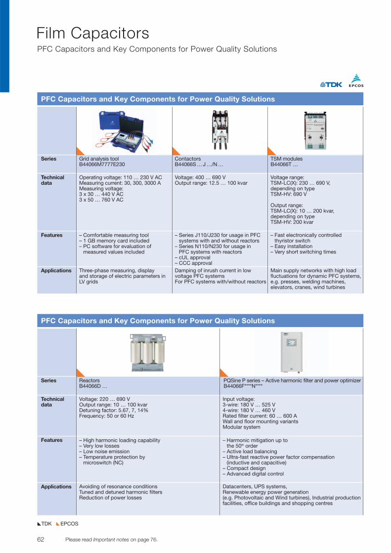
62 Please read Important notes on page 76. © TDK-EPC Corporation 2010
Film CapacitorsPFC Capacitors and Key Components for Power Quality Solutions
EPCOSTDK
Series Grid analysis tool Contactors TSM modulesB44066M7777E230 B44066S … J …/N … B44066T …
Technicaldata
Features
Applications
PFC Capacitors and Key Components for Power Quality Solutions
Operating voltage: 110 … 230 V ACMeasuring current: 30, 300, 3000 AMeasuring voltage:3 x 30 … 440 V AC3 x 50 … 760 V AC
– Comfortable measuring tool– 1 GB memory card included– PC software for evaluation of
measured values included
Voltage: 400 … 690 VOutput range: 12.5 … 100 kvar
– Series J110/J230 for usage in PFCsystems with and without reactors
– Series N110/N230 for usage in PFC systems with reactors
– cUL approval– CCC approval
Voltage range: TSM-LC(X): 230 … 690 V, depending on typeTSM-HV: 690 V
Output range: TSM-LC(X): 10 … 200 kvar, depending on typeTSM-HV: 200 kvar
– Fast electronically controlled thyristor switch
– Easy installation– Very short switching times
Three-phase measuring, display and storage of electric parameters inLV grids
Damping of inrush current in low voltage PFC systemsFor PFC systems with/without reactors
Main supply networks with high loadfluctuations for dynamic PFC systems,e.g. presses, welding machines, elevators, cranes, wind turbines
Series Reactors PQSine P series – Active harmonic filter and power optimizerB44066D … B44066F****N****
Technicaldata
Features
Applications
PFC Capacitors and Key Components for Power Quality Solutions
Voltage: 220 … 690 VOutput range: 10 … 100 kvarDetuning factor: 5.67, 7, 14%Frequency: 50 or 60 Hz
– High harmonic loading capability– Very low losses– Low noise emission– Temperature protection by
microswitch (NC)
Avoiding of resonance conditionsTuned and detuned harmonic filtersReduction of power losses
Input voltage:3-wire: 180 V … 525 V4-wire: 180 V … 460 VRated filter current: 60 … 600 AWall and floor mounting variantsModular system
– Harmonic mitigation up to the 50th order
– Active load balancing– Ultra-fast reactive power factor compensation
(inductive and capacitive)– Compact design– Advanced digital control
Datacenters, UPS systems, Renewable energy power generation (e.g. Photovoltaic and Wind turbines), Industrial productionfacilities, office buildings and shopping centres
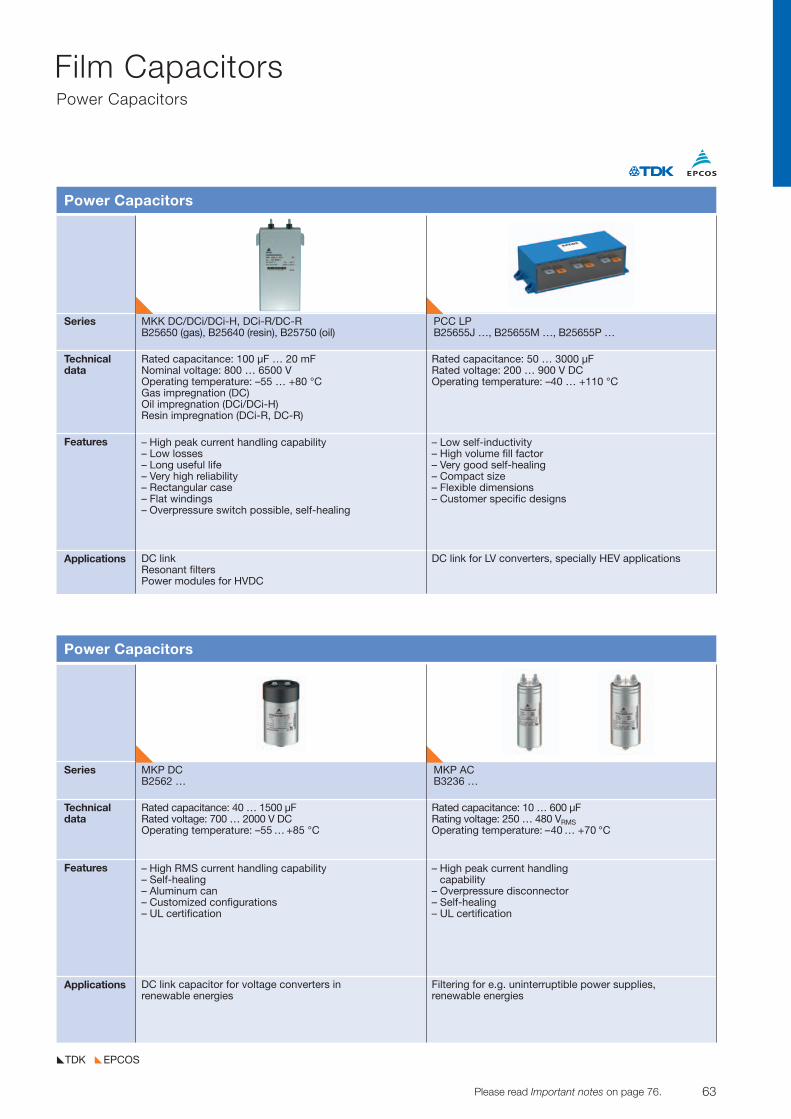
63© TDK-EPC Corporation 2010 Please read Important notes on page 76.
Film CapacitorsPower Capacitors
EPCOSTDK
Series MKP DC MKP ACB2562 … B3236 …
Technicaldata
Features
Applications
Power Capacitors
Rated capacitance: 40 … 1500 µFRated voltage: 700 … 2000 V DCOperating temperature: –55 … +85 °C
– High RMS current handling capability– Self-healing– Aluminum can– Customized configurations– UL certification
DC link capacitor for voltage converters in renewable energies
Rated capacitance: 10 … 600 µFRating voltage: 250 … 480 VRMSOperating temperature: –40 … +70 °C
– High peak current handling capability
– Overpressure disconnector– Self-healing– UL certification
Filtering for e.g. uninter ruptible power supplies, renewable energies
Series MKK DC/DCi/DCi-H, DCi-R/DC-R PCC LPB25650 (gas), B25640 (resin), B25750 (oil) B25655J …, B25655M …, B25655P …
Technicaldata
Features
Applications
Power Capacitors
Rated capacitance: 100 µF … 20 mFNominal voltage: 800 … 6500 VOperating temperature: –55 … +80 °CGas impregnation (DC)Oil impregnation (DCi/DCi-H)Resin impregnation (DCi-R, DC-R)
– High peak current handling capability– Low losses– Long useful life– Very high reliability – Rectangular case– Flat windings– Overpressure switch possible, self-healing
DC link Resonant filtersPower modules for HVDC
Rated capacitance: 50 … 3000 µFRated voltage: 200 … 900 V DCOperating temperature: –40 … +110 °C
– Low self-inductivity– High volume fill factor– Very good self-healing– Compact size– Flexible dimensions– Customer specific designs
DC link for LV converters, specially HEV applications
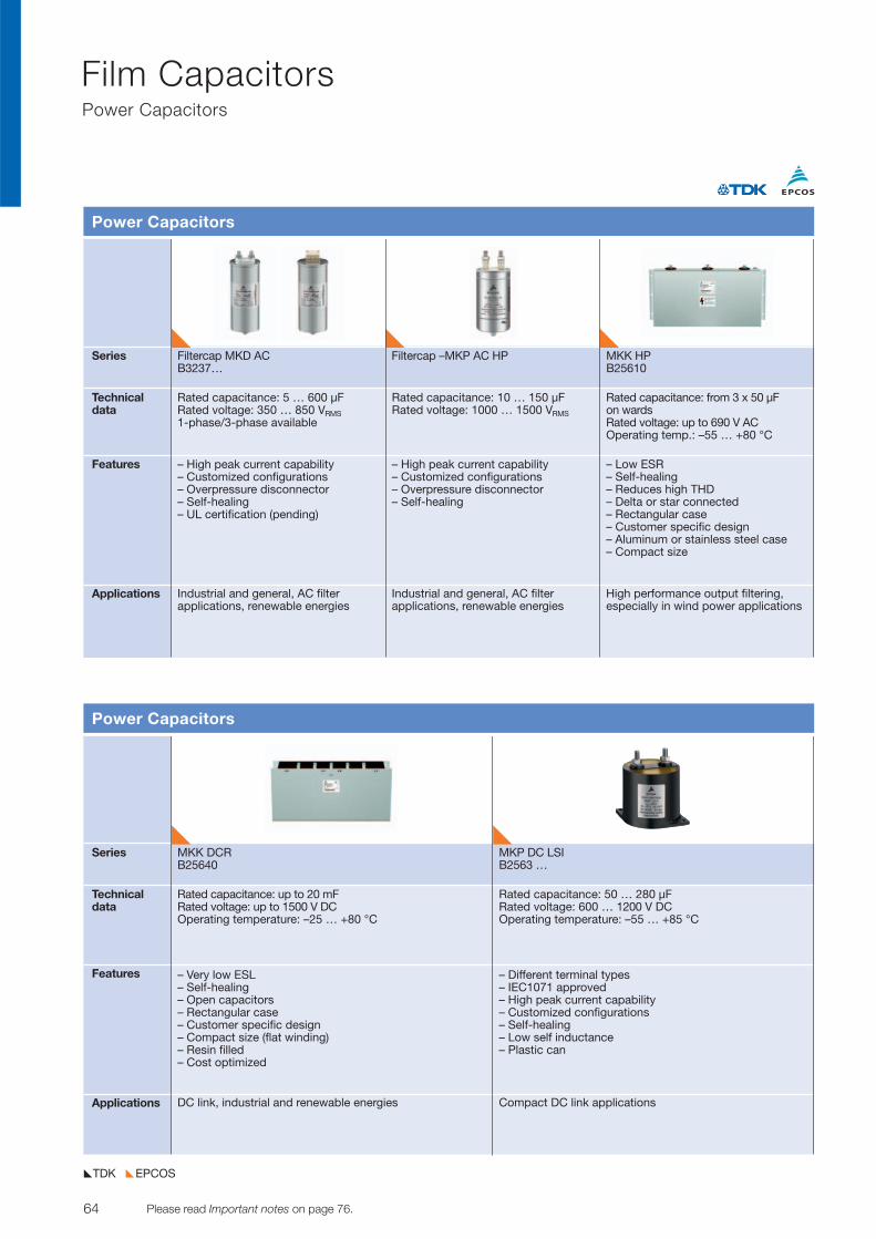
64 Please read Important notes on page 76. © TDK-EPC Corporation 2010
Film CapacitorsPower Capacitors
EPCOSTDK
Series MKK DCR MKP DC LSIB25640 B2563 …
Technicaldata
Features
Applications
Power Capacitors
Rated capacitance: up to 20 mFRated voltage: up to 1500 V DCOperating temperature: –25 … +80 °C
– Very low ESL– Self-healing– Open capacitors– Rectangular case– Customer specific design– Compact size (flat winding)– Resin filled– Cost optimized
DC link, industrial and renewable energies
Rated capacitance: 50 … 280 µFRated voltage: 600 … 1200 V DCOperating temperature: –55 … +85 °C
– Different terminal types– IEC1071 approved– High peak current capability– Customized configurations– Self-healing– Low self inductance– Plastic can
Compact DC link applications
Series Filtercap MKD AC Filtercap –MKP AC HP MKK HPB3237… B25610
Technicaldata
Features
Applications
Power Capacitors
Rated capacitance: 5 … 600 µFRated voltage: 350 … 850 VRMS1-phase/3-phase available
– High peak current capability– Customized configurations– Overpressure disconnector– Self-healing– UL certification (pending)
Rated capacitance: 10 … 150 µFRated voltage: 1000 … 1500 VRMS
– High peak current capability– Customized configurations– Overpressure disconnector– Self-healing
Rated capacitance: from 3 x 50 µF on wardsRated voltage: up to 690 V AC Operating temp.: –55 … +80 °C
– Low ESR– Self-healing– Reduces high THD– Delta or star connected– Rectangular case– Customer specific design– Aluminum or stainless steel case– Compact size
Industrial and general, AC filter applications, renewable energies
Industrial and general, AC filter applications, renewable energies
High performance output filtering, especially in wind power applications
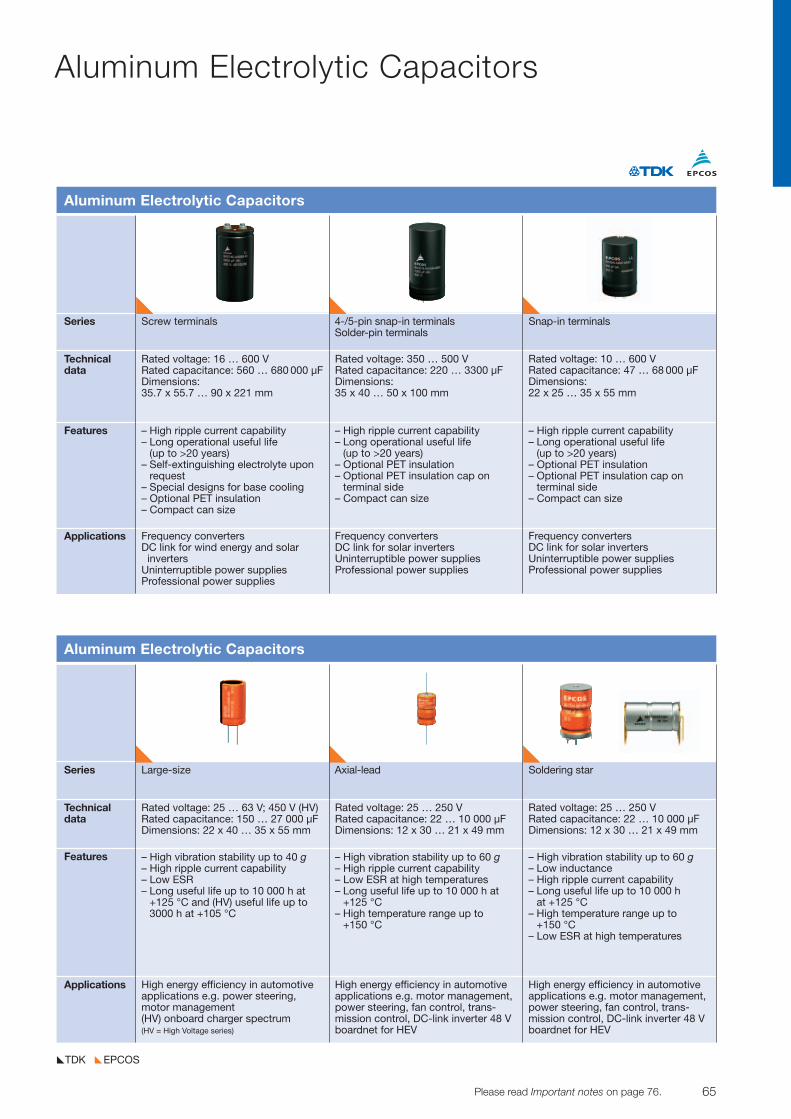
65© TDK-EPC Corporation 2010 Please read Important notes on page 76.
Aluminum Electrolytic Capacitors
EPCOSTDK
Series Large-size Axial-lead Soldering star
Technicaldata
Features
Applications
Aluminum Electrolytic Capacitors
Rated voltage: 25 … 63 V; 450 V (HV)Rated capacitance: 150 … 27 000 µFDimensions: 22 x 40 … 35 x 55 mm
– High vibration stability up to 40 g– High ripple current capability– Low ESR – Long useful life up to 10 000 h at
+125 °C and (HV) useful life up to3000 h at +105 °C
Rated voltage: 25 … 250 VRated capacitance: 22 … 10 000 µFDimensions: 12 x 30 … 21 x 49 mm
– High vibration stability up to 60 g– High ripple current capability– Low ESR at high temperatures– Long useful life up to 10 000 h at
+125 °C– High temperature range up to
+150 °C
Rated voltage: 25 … 250 VRated capacitance: 22 … 10 000 µFDimensions: 12 x 30 … 21 x 49 mm
– High vibration stability up to 60 g– Low inductance– High ripple current capability– Long useful life up to 10 000 h
at +125 °C– High temperature range up to
+150 °C– Low ESR at high temperatures
High energy efficiency in automotiveapplications e.g. power steering, motor management(HV) onboard charger spectrum(HV = High Voltage series)
High energy efficiency in automotiveapplications e.g. motor management,power steering, fan control, trans -mission control, DC-link inverter 48 Vboardnet for HEV
High energy efficiency in automotiveapplications e.g. motor management,power steering, fan control, trans -mission control, DC-link inverter 48 Vboardnet for HEV
Series Screw terminals 4-/5-pin snap-in terminals Snap-in terminalsSolder-pin terminals
Technicaldata
Features
Applications
Aluminum Electrolytic Capacitors
Rated voltage: 16 … 600 VRated capacitance: 560 … 680 000 µFDimensions:35.7 x 55.7 … 90 x 221 mm
– High ripple current capability– Long operational useful life
(up to >20 years)– Self-extinguishing electrolyte upon
request– Special designs for base cooling– Optional PET insulation– Compact can size
Rated voltage: 350 … 500 VRated capacitance: 220 … 3300 µFDimensions:35 x 40 … 50 x 100 mm
– High ripple current capability– Long operational useful life
(up to >20 years)– Optional PET insulation– Optional PET insulation cap on
terminal side– Compact can size
Rated voltage: 10 … 600 VRated capacitance: 47 … 68 000 µFDimensions:22 x 25 … 35 x 55 mm
Frequency convertersDC link for wind energy and solar invertersUninterruptible power suppliesProfessional power supplies
Frequency convertersDC link for solar invertersUninterruptible power suppliesProfessional power supplies
– High ripple current capability– Long operational useful life
(up to >20 years)– Optional PET insulation– Optional PET insulation cap on
terminal side– Compact can size
Frequency converters DC link for solar invertersUninterruptible power suppliesProfessional power supplies
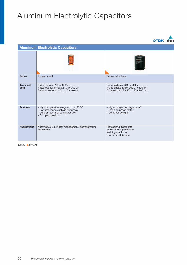
66 Please read Important notes on page 76. © TDK-EPC Corporation 2010
Aluminum Electrolytic Capacitors
EPCOSTDK
Series Single-ended Pulse applications
Technicaldata
Features
Applications
Aluminum Electrolytic Capacitors
Rated voltage: 10 … 450 VRated capacitance: 2.2 … 10 000 µFDimensions: 8 x 11.5 … 18 x 40 mm
– High temperature range up to +135 °C– Low impedance at high frequency– Different terminal configurations– Compact designs
Rated voltage: 300 … 500 VRated capacitance: 200 … 6600 µFDimensions: 25 x 45 … 50 x 100 mm
– High charge/discharge proof – Low dissipation factor– Compact designs
Automotive e.g. motor management, power steering, fan control
Professional flashlightsMobile X-ray generatorsWelding machinesHair removal devices
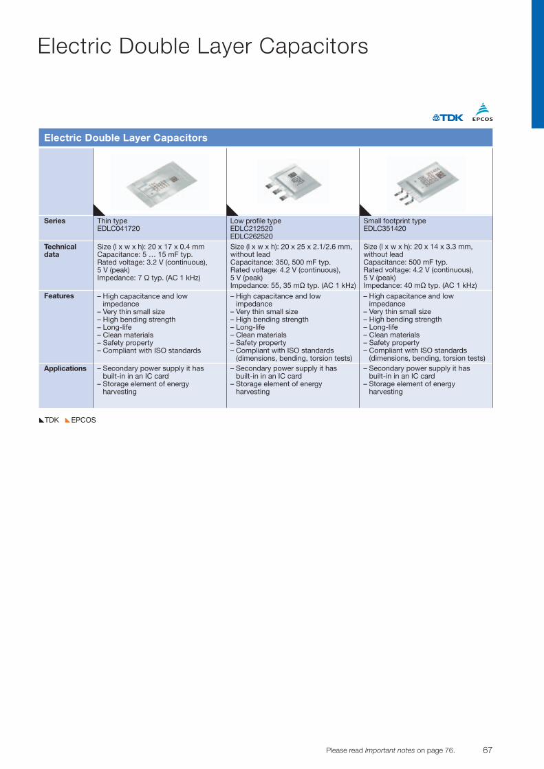
67© TDK-EPC Corporation 2010 Please read Important notes on page 76.
Electric Double Layer Capacitors
EPCOSTDK
Series Thin type Low profile type Small footprint typeEDLC041720 EDLC212520 EDLC351420
EDLC262520Technicaldata
Features
Applications
Electric Double Layer Capacitors
Size (l x w x h): 20 x 17 x 0.4 mmCapacitance: 5 … 15 mF typ.Rated voltage: 3.2 V (continuous), 5 V (peak)Impedance: 7 V typ. (AC 1 kHz)
– High capacitance and low impedance
– Very thin small size– High bending strength– Long-life– Clean materials– Safety property– Compliant with ISO standards
Size (l x w x h): 20 x 25 x 2.1/2.6 mm,without leadCapacitance: 350, 500 mF typ.Rated voltage: 4.2 V (continuous), 5 V (peak)Impedance: 55, 35 mV typ. (AC 1 kHz)
– High capacitance and low impedance
– Very thin small size– High bending strength– Long-life– Clean materials– Safety property– Compliant with ISO standards
(dimensions, bending, torsion tests)
Size (l x w x h): 20 x 14 x 3.3 mm, without leadCapacitance: 500 mF typ.Rated voltage: 4.2 V (continuous), 5 V (peak)Impedance: 40 mV typ. (AC 1 kHz)
– High capacitance and low impedance
– Very thin small size– High bending strength– Long-life– Clean materials– Safety property– Compliant with ISO standards
(dimensions, bending, torsion tests)– Secondary power supply it has
built-in in an IC card– Storage element of energy
harvesting
– Secondary power supply it has built-in in an IC card
– Storage element of energy harvesting
– Secondary power supply it has built-in in an IC card
– Storage element of energy harvesting
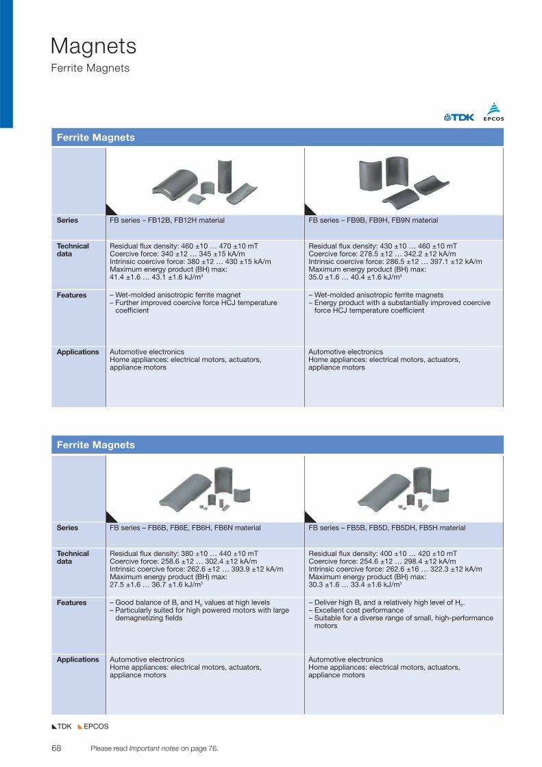
68 Please read Important notes on page 76. © TDK-EPC Corporation 2010
MagnetsFerrite Magnets
EPCOSTDK
Series FB series – FB12B, FB12H material FB series – FB9B, FB9H, FB9N material
Technicaldata
Features
Applications
Ferrite Magnets
Residual flux density: 460 ±10 … 470 ±10 mTCoercive force: 340 ±12 … 345 ±15 kA/mIntrinsic coercive force: 380 ±12 … 430 ±15 kA/mMaximum energy product (BH) max:41.4 ±1.6 … 43.1 ±1.6 kJ/m3
– Wet-molded anisotropic ferrite magnet– Further improved coercive force HCJ temperature
coefficient
– Wet-molded anisotropic ferrite magnets– Energy product with a substantially improved coercive
force HCJ temperature coefficient
Automotive electronicsHome appliances: electrical motors, actuators, appliance motors
Automotive electronicsHome appliances: electrical motors, actuators, appliance motors
Residual flux density: 430 ±10 … 460 ±10 mTCoercive force: 278.5 ±12 … 342.2 ±12 kA/mIntrinsic coercive force: 286.5 ±12 … 397.1 ±12 kA/mMaximum energy product (BH) max:35.0 ±1.6 … 40.4 ±1.6 kJ/m3
Series FB series – FB6B, FB6E, FB6H, FB6N material FB series – FB5B, FB5D, FB5DH, FB5H material
Technicaldata
Features
Applications
Ferrite Magnets
Residual flux density: 380 ±10 … 440 ±10 mTCoercive force: 258.6 ±12 … 302.4 ±12 kA/mIntrinsic coercive force: 262.6 ±12 … 393.9 ±12 kA/mMaximum energy product (BH) max:27.5 ±1.6 … 36.7 ±1.6 kJ/m3
– Good balance of Br and Hc values at high levels– Particularly suited for high powered motors with large
demagnetizing fields
– Deliver high Br and a relatively high level of Hc.– Excellent cost performance– Suitable for a diverse range of small, high-performance
motors
Automotive electronicsHome appliances: electrical motors, actuators, appliance motors
Automotive electronicsHome appliances: electrical motors, actuators, appliance motors
Residual flux density: 400 ±10 … 420 ±10 mTCoercive force: 254.6 ±12 … 298.4 ±12 kA/mIntrinsic coercive force: 262.6 ±16 … 322.3 ±12 kA/mMaximum energy product (BH) max:30.3 ±1.6 … 33.4 ±1.6 kJ/m3
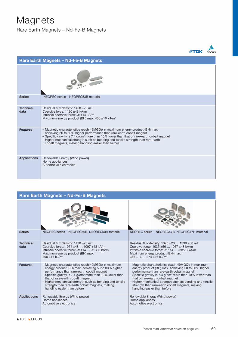
69© TDK-EPC Corporation 2010 Please read Important notes on page 76.
MagnetsRare Earth Magnets – Nd-Fe-B Magnets
EPCOSTDK
Series NEOREC series – NEOREC53B material
Technicaldata
Features
Applications
Rare Earth Magnets – Nd-Fe-B Magnets
Residual flux density: 1450 ±20 mTCoercive force: 1120 ±48 kA/mIntrinsic coercive force: ≥1114 kA/mMaximum energy product (BH) max: 406 ±16 kJ/m3
– Magnetic characteristics reach 49MGOe in maximum energy product (BH) max. achieving 50 to 80% higher performance than rare-earth cobalt magnet
– Specific gravity is 7.4 g/cm3 more than 10% lower than that of rare-earth cobalt magnet– Higher mechanical strength such as bending and tensile strength than rare-earth
cobalt magnets, making handling easier than before
Renewable Energy (Wind power)Home appliancesAutomotive electronics
Series NEOREC series – NEOREC50B, NEOREC50H material NEOREC series – NEOREC47B, NEOREC47H material
Technicaldata
Features
Applications
Rare Earth Magnets – Nd-Fe-B Magnets
Residual flux density: 1420 ±20 mTCoercive force: 1074 ±48 … 1097 ±48 kA/mIntrinsic coercive force: ≥1114 … ≥1353 kA/mMaximum energy product (BH) max:390 ±16 kJ/m3
– Magnetic characteristics reach 49MGOe in maximumenergy product (BH) max. achieving 50 to 80% higherperformance than rare-earth cobalt magnet
– Specific gravity is 7.4 g/cm3 more than 10% lower thanthat of rare-earth cobalt magnet
– Higher mechanical strength such as bending and tensilestrength than rare-earth cobalt magnets, makinghandling easier than before
Renewable Energy (Wind power)Home appliancesAutomotive electronics
Renewable Energy (Wind power)Home appliancesAutomotive electronics
Residual flux density: 1390 ±20 … 1390 ±30 mTCoercive force: 1035 ±56 … 1067 ±48 kA/mIntrinsic coercive force: ≥1114 … ≥1273 kA/mMaximum energy product (BH) max:366 ±16 … 374 ±16 kJ/m3
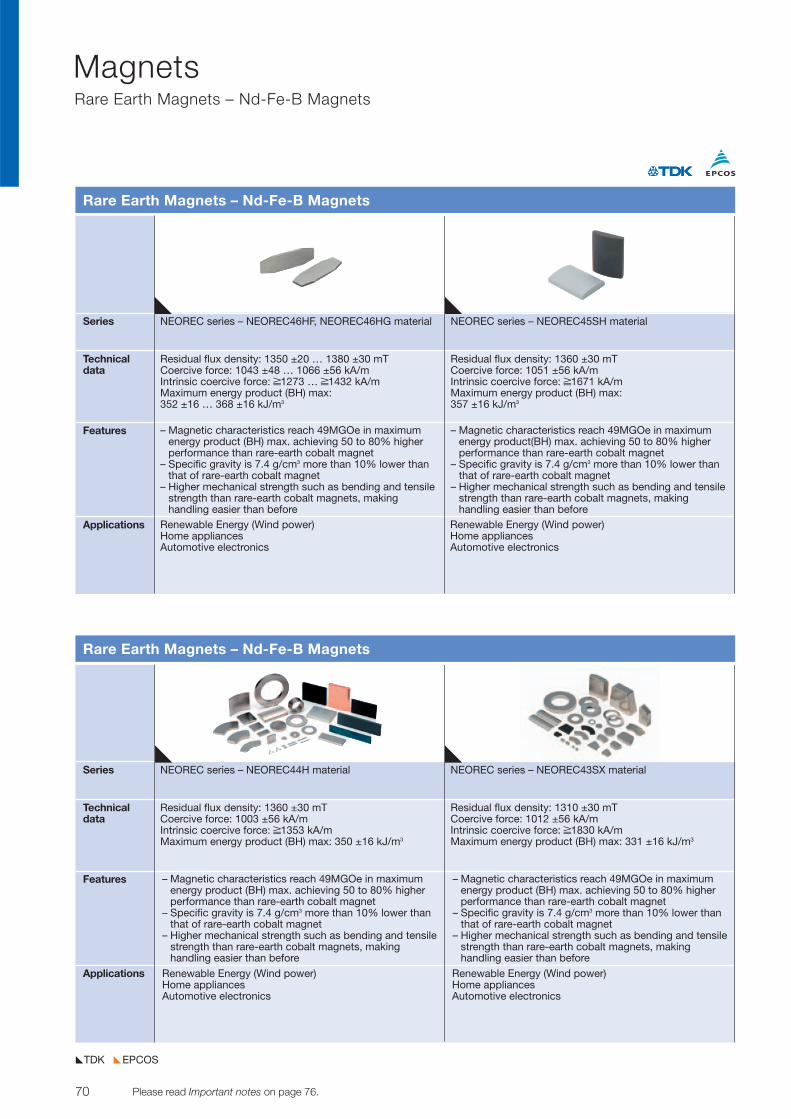
70 Please read Important notes on page 76. © TDK-EPC Corporation 2010
MagnetsRare Earth Magnets – Nd-Fe-B Magnets
Series NEOREC series – NEOREC46HF, NEOREC46HG material NEOREC series – NEOREC45SH material
Technicaldata
Features
Applications
Rare Earth Magnets – Nd-Fe-B Magnets
Residual flux density: 1350 ±20 … 1380 ±30 mTCoercive force: 1043 ±48 … 1066 ±56 kA/mIntrinsic coercive force: ≥1273 … ≥1432 kA/mMaximum energy product (BH) max:352 ±16 … 368 ±16 kJ/m3
– Magnetic characteristics reach 49MGOe in maximumenergy product (BH) max. achieving 50 to 80% higherperformance than rare-earth cobalt magnet
– Specific gravity is 7.4 g/cm3 more than 10% lower thanthat of rare-earth cobalt magnet
– Higher mechanical strength such as bending and tensilestrength than rare-earth cobalt magnets, makinghandling easier than before
– Magnetic characteristics reach 49MGOe in maximumenergy product(BH) max. achieving 50 to 80% higherperformance than rare-earth cobalt magnet
– Specific gravity is 7.4 g/cm3 more than 10% lower thanthat of rare-earth cobalt magnet
– Higher mechanical strength such as bending and tensilestrength than rare-earth cobalt magnets, makinghandling easier than before
Residual flux density: 1360 ±30 mTCoercive force: 1051 ±56 kA/mIntrinsic coercive force: ≥1671 kA/mMaximum energy product (BH) max:357 ±16 kJ/m3
Renewable Energy (Wind power)Home appliancesAutomotive electronics
Renewable Energy (Wind power)Home appliancesAutomotive electronics
Series NEOREC series – NEOREC44H material NEOREC series – NEOREC43SX material
Technicaldata
Features
Applications
Rare Earth Magnets – Nd-Fe-B Magnets
Residual flux density: 1360 ±30 mTCoercive force: 1003 ±56 kA/mIntrinsic coercive force: ≥1353 kA/mMaximum energy product (BH) max: 350 ±16 kJ/m3
– Magnetic characteristics reach 49MGOe in maximumenergy product (BH) max. achieving 50 to 80% higherperformance than rare-earth cobalt magnet
– Specific gravity is 7.4 g/cm3 more than 10% lower thanthat of rare-earth cobalt magnet
– Higher mechanical strength such as bending and tensilestrength than rare-earth cobalt magnets, makinghandling easier than before
Renewable Energy (Wind power)Home appliancesAutomotive electronics
Renewable Energy (Wind power)Home appliancesAutomotive electronics
Residual flux density: 1310 ±30 mTCoercive force: 1012 ±56 kA/mIntrinsic coercive force: ≥1830 kA/mMaximum energy product (BH) max: 331 ±16 kJ/m3
EPCOSTDK
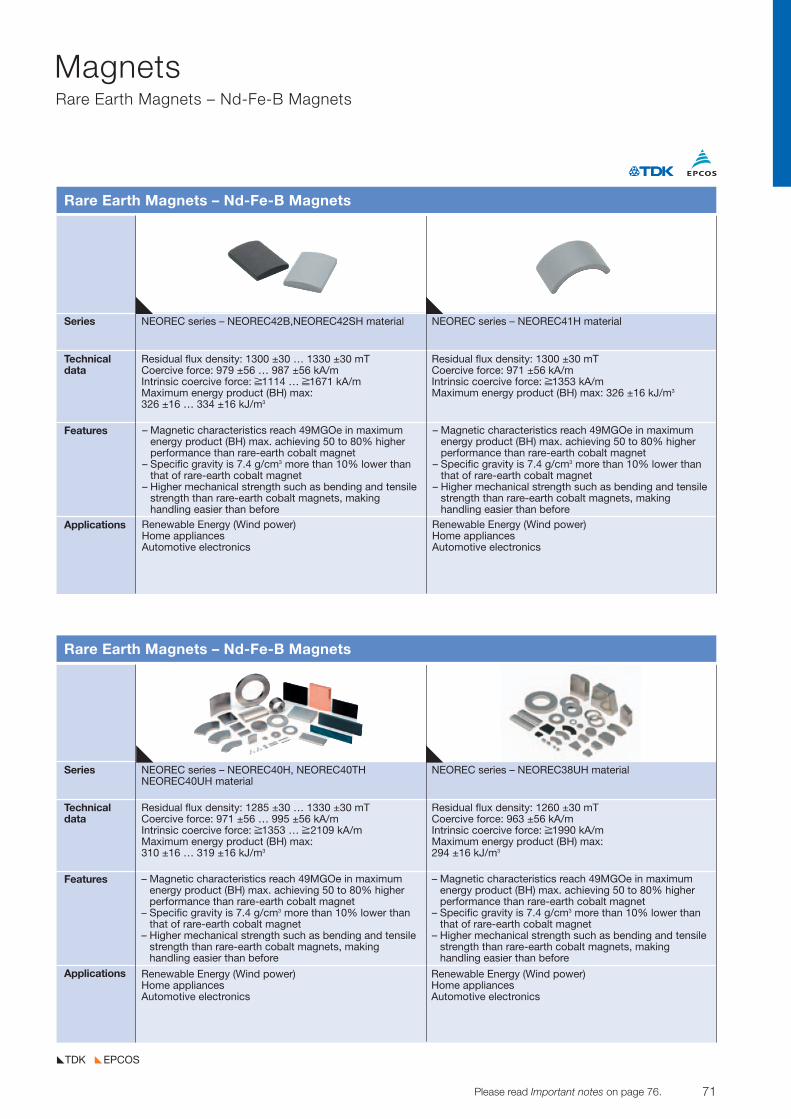
71© TDK-EPC Corporation 2010 Please read Important notes on page 76.
MagnetsRare Earth Magnets – Nd-Fe-B Magnets
EPCOSTDK
Series NEOREC series – NEOREC42B,NEOREC42SH material NEOREC series – NEOREC41H material
Technicaldata
Features
Applications
Rare Earth Magnets – Nd-Fe-B Magnets
Residual flux density: 1300 ±30 … 1330 ±30 mTCoercive force: 979 ±56 … 987 ±56 kA/mIntrinsic coercive force: ≥1114 … ≥1671 kA/mMaximum energy product (BH) max:326 ±16 … 334 ±16 kJ/m3
– Magnetic characteristics reach 49MGOe in maximumenergy product (BH) max. achieving 50 to 80% higherperformance than rare-earth cobalt magnet
– Specific gravity is 7.4 g/cm3 more than 10% lower thanthat of rare-earth cobalt magnet
– Higher mechanical strength such as bending and tensilestrength than rare-earth cobalt magnets, makinghandling easier than before
Residual flux density: 1300 ±30 mTCoercive force: 971 ±56 kA/mIntrinsic coercive force: ≥1353 kA/mMaximum energy product (BH) max: 326 ±16 kJ/m3
Renewable Energy (Wind power)Home appliancesAutomotive electronics
Renewable Energy (Wind power)Home appliancesAutomotive electronics
Series NEOREC series – NEOREC40H, NEOREC40TH NEOREC series – NEOREC38UH materialNEOREC40UH material
Technicaldata
Features
Applications
Rare Earth Magnets – Nd-Fe-B Magnets
Residual flux density: 1285 ±30 … 1330 ±30 mTCoercive force: 971 ±56 … 995 ±56 kA/mIntrinsic coercive force: ≥1353 … ≥2109 kA/mMaximum energy product (BH) max:310 ±16 … 319 ±16 kJ/m3
– Magnetic characteristics reach 49MGOe in maximumenergy product (BH) max. achieving 50 to 80% higherperformance than rare-earth cobalt magnet
– Specific gravity is 7.4 g/cm3 more than 10% lower thanthat of rare-earth cobalt magnet
– Higher mechanical strength such as bending and tensilestrength than rare-earth cobalt magnets, makinghandling easier than before
Renewable Energy (Wind power)Home appliancesAutomotive electronics
Renewable Energy (Wind power)Home appliancesAutomotive electronics
Residual flux density: 1260 ±30 mTCoercive force: 963 ±56 kA/mIntrinsic coercive force: ≥1990 kA/mMaximum energy product (BH) max:294 ±16 kJ/m3
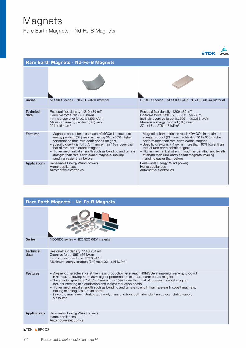
72 Please read Important notes on page 76. © TDK-EPC Corporation 2010
MagnetsRare Earth Magnets – Nd-Fe-B Magnets
Series NEOREC series – NEOREC37H material NEOREC series – NEOREC35NX, NEOREC35UX material
Technicaldata
Features
Applications
Rare Earth Magnets - Nd-Fe-B Magnets
Residual flux density: 1240 ±30 mTCoercive force: 923 ±56 kA/mIntrinsic coercive force: ≥1353 kA/mMaximum energy product (BH) max:294 ±16 kJ/m3
– Magnetic characteristics reach 49MGOe in maximumenergy product (BH) max. achieving 50 to 80% higherperformance than rare-earth cobalt magnet
– Specific gravity is 7.4 g /cm3 more than 10% lower thanthat of rare-earth cobalt magnet
– Higher mechanical strength such as bending and tensilestrength than rare-earth cobalt magnets, makinghandling easier than before
– Magnetic characteristics reach 49MGOe in maximumenergy product (BH) max. achieving 50 to 80% higherperformance than rare-earth cobalt magnet
– Specific gravity is 7.4 g/cm3 more than 10% lower thanthat of rare-earth cobalt magnet
– Higher mechanical strength such as bending and tensilestrength than rare-earth cobalt magnets, makinghandling easier than before
Residual flux density: 1200 ±30 mTCoercive force: 920 ±56 … 923 ±56 kA/mIntrinsic coercive force: ≥2626 … ≥2388 kA/mMaximum energy product (BH) max:271 ±16 … 278 ±16 kJ/m3
Renewable Energy (Wind power)Home appliancesAutomotive electronics
Renewable Energy (Wind power)Home appliancesAutomotive electronics
Series NEOREC series – NEOREC30EV material
Technicaldata
Features
Applications
Rare Earth Magnets – Nd-Fe-B Magnets
Residual flux density: 1140 ±30 mTCoercive force: 867 ±56 kA/mIntrinsic coercive force: ≥756 kA/mMaximum energy product (BH) max: 231 ±16 kJ/m3
– Magnetic characteristics at the mass production level reach 49MGOe in maximum energy product(BH) max. achieving 50 to 80% higher performance than rare-earth cobalt magnet
– The specific gravity is 7.4 g/cm3 more than 10% lower than that of rare-earth cobalt magnet.Ideal for meeting miniaturization and weight reduction needs
– Higher mechanical strength such as bending and tensile strength than rare-earth cobalt magnets,making handling easier than before
– Since the main raw materials are neodymium and iron, both abundant resources, stable supplyis assured
Renewable Energy (Wind power)Home appliancesAutomotive electronics
EPCOSTDK
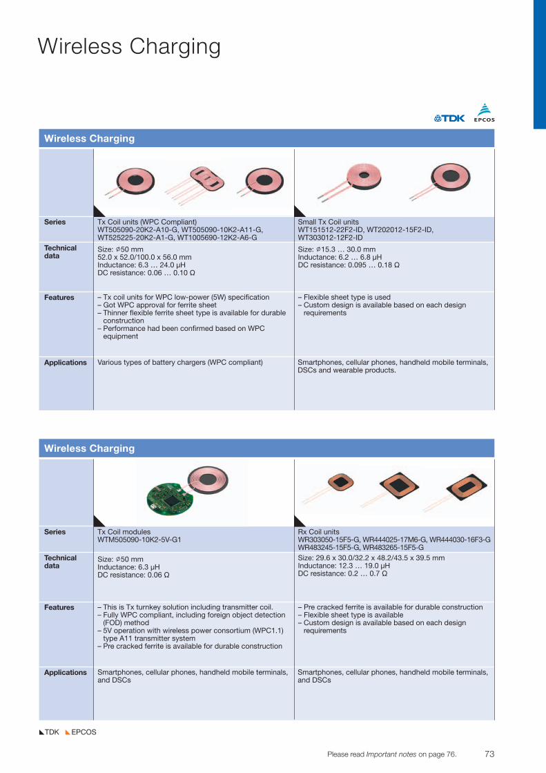
73© TDK-EPC Corporation 2010 Please read Important notes on page 76.
Wireless Charging
EPCOSTDK
Series Tx Coil units (WPC Compliant) Small Tx Coil unitsWT505090-20K2-A10-G, WT505090-10K2-A11-G, WT151512-22F2-ID, WT202012-15F2-ID,WT525225-20K2-A1-G, WT1005690-12K2-A6-G WT303012-12F2-ID
Technicaldata
Features
Applications
Wireless Charging
Size: ˇ50 mm52.0 x 52.0/100.0 x 56.0 mmInductance: 6.3 … 24.0 µHDC resistance: 0.06 … 0.10 V
– Tx coil units for WPC low-power (5W) specification– Got WPC approval for ferrite sheet– Thinner flexible ferrite sheet type is available for durable
construction– Performance had been confirmed based on WPC
equipment
– Flexible sheet type is used– Custom design is available based on each design
requirements
Size: ˇ15.3 … 30.0 mmInductance: 6.2 … 6.8 µHDC resistance: 0.095 … 0.18 V
Various types of battery chargers (WPC compliant) Smartphones, cellular phones, handheld mobile terminals,DSCs and wearable products.
Series Tx Coil modules Rx Coil unitsWTM505090-10K2-5V-G1 WR303050-15F5-G, WR444025-17M6-G, WR444030-16F3-G
WR483245-15F5-G, WR483265-15F5-GTechnicaldata
Features
Applications
Wireless Charging
Size: ˇ50 mmInductance: 6.3 µHDC resistance: 0.06 V
– This is Tx turnkey solution including transmitter coil.– Fully WPC compliant, including foreign object detection
(FOD) method– 5V operation with wireless power consortium (WPC1.1)
type A11 transmitter system– Pre cracked ferrite is available for durable construction
– Pre cracked ferrite is available for durable construction– Flexible sheet type is available– Custom design is available based on each design
requirements
Size: 29.6 x 30.0/32.2 x 48.2/43.5 x 39.5 mmInductance: 12.3 … 19.0 µHDC resistance: 0.2 … 0.7 V
Smartphones, cellular phones, handheld mobile terminals,and DSCs
Smartphones, cellular phones, handheld mobile terminals,and DSCs
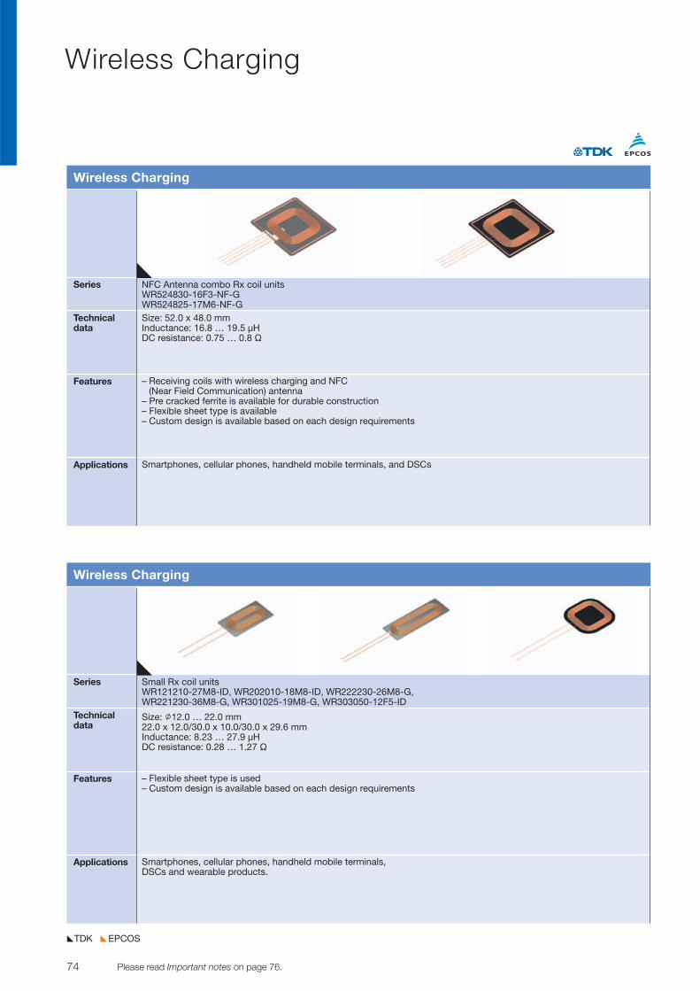
Wireless Charging
EPCOSTDK
74 Please read Important notes on page 76. © TDK-EPC Corporation 2010
Series NFC Antenna combo Rx coil unitsWR524830-16F3-NF-GWR524825-17M6-NF-G
Technicaldata
Features
Applications
Wireless Charging
Size: 52.0 x 48.0 mmInductance: 16.8 … 19.5 µHDC resistance: 0.75 … 0.8 V
– Receiving coils with wireless charging and NFC (Near Field Communication) antenna
– Pre cracked ferrite is available for durable construction– Flexible sheet type is available– Custom design is available based on each design requirements
Smartphones, cellular phones, handheld mobile terminals, and DSCs
Series Small Rx coil unitsWR121210-27M8-ID, WR202010-18M8-ID, WR222230-26M8-G,WR221230-36M8-G, WR301025-19M8-G, WR303050-12F5-ID
Technicaldata
Features
Applications
Wireless Charging
Size: ˇ12.0 … 22.0 mm22.0 x 12.0/30.0 x 10.0/30.0 x 29.6 mmInductance: 8.23 … 27.9 µHDC resistance: 0.28 … 1.27 V
– Flexible sheet type is used– Custom design is available based on each design requirements
Smartphones, cellular phones, handheld mobile terminals,DSCs and wearable products.
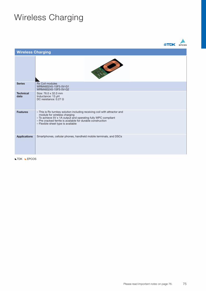
75© TDK-EPC Corporation 2010 Please read Important notes on page 76.
Wireless Charging
EPCOSTDK
Series Rx Coil modulesWRM483245-15F5-5V-G1WRM483245-15F5-5V-G2
Technicaldata
Features
Applications
Wireless Charging
Size: 76.0 x 32.0 mmInductance: 13 µHDC resistance: 0.27 V
– This is Rx turnkey solution including receiving coil with attractor andmodule for wireless charging
– To achieve 5V x 1A output and operating fully WPC compliant– Pre cracked ferrite is available for durable construction– Flexible sheet type is available
Smartphones, cellular phones, handheld mobile terminals, and DSCs
Important Notes
76
The following applies to all products named in this publication:
1. Some parts of this publication contain statements aboutthe suitability of our products for certain areas of ap-plication. These statements are based on our knowledgeof typical requirements that are often placed on our prod-ucts in the areas of application concerned. We neverthe-less expressly point out that such statements cannot beregarded as binding statements about the suitabilityof our products for a particular customer application.As a rule, EPCOS is either unfamiliar with individual cus-tomer applications or less familiar with them than the customers themselves. For these reasons, it is always ul-timately incumbent on the customer to check and decidewhether an EPCOS product with the properties describedin the product specification is suitable for use in a partic-ular customer application.
2. We also point out that in individual cases, a malfunc-tion of electronic components or failure before theend of their usual service life cannot be completelyruled out in the current state of the art, even if they areoperated as speci fied. In customer applications requir-ing a very high level of operational safety and especially in customer applications in which the malfunction or failureof an electronic component could endanger human life orhealth (e.g. in accident prevention or life-saving systems),it must therefore be ensured by means of suitable designof the customer application or other action taken by the customer (e.g. installation of protective circuitry or redundancy) that no injury or damage is sustained by thirdparties in the event of malfunction or failure of an electron-ic component.
3. The warnings, cautions and product-specific notesmust be observed.
4. In order to satisfy certain technical requirements, some ofthe products described in this publica tion may containsubstances subject to restrictions in cer tain jurisdic-tions (e.g. because they are classed as hazardous).Useful information on this will be found in our MaterialData Sheets on the Internet (www.epcos.com/material).Should you have any more detailed questions, please con-tact our sales offices.
5. We constantly strive to improve our products. Conse -quently, the products described in this publicationmay change from time to time. The same is true of thecorresponding product specifications. Please checktherefore to what extent product descriptions and speci-fications contained in this publication are still applicablebefore or when you place an order.
We also reserve the right to discontinue productionand delivery of products. Consequently, we cannotguarantee that all products named in this publication willalways be available.
The aforementioned does not apply in the case of individual agreements deviating from the foregoing forcustomer-specific products.
6. Unless otherwise agreed in individual contracts, all orders are subject to the current version of the “Gen-eral Terms of Delivery for Products and Services in the Electrical Industry” published by the GermanElectrical and Electronics Industry Association (ZVEI).
7. The trade names EPCOS, CeraDiode, CeraLink, CeraPad,CeraPlas, CSMP, CSSP, CTVS, DeltaCap, DigiSiMic,DSSP, ExoCore, FilterCap, FormFit, LeaXield, MiniBlue,MiniCell, MKD, MKK, MotorCap, PCC, PhaseCap, PhaseCube, PhaseMod, PhiCap, PQSine, SIFERRIT,SIFI, SIKOREL, SilverCap, SIMDAD, SiMic, SIMID, SineFormer, SIOV, SIP5D, SIP5K, TFAP, ThermoFuse,WindCap are trademarks regis tered or pending in Europe and in other countries. Further information will be found on the Internet at www.epcos.com/trademarks.

77
The world of electronic components, modules and systems within a mouse click
www.epcos.comwww.global.tdk.com


© EPCOS AG · A TDK Group CompanyEdition 2017 · Ordering No. EPC:65069-7600 · Printed in Germany · PP 01178.


