1 Introduction This document provides the guidelines and specifications required to correctly configure a TDM Gateway to work with AT&T IP Flexible Reach Service (including Enhanced Features Service) and/or AT&T IP Toll-Free, on AT&T VPN Service (“AT&T VPN”) as the Underlying Transport Service. CERs can be utilized for either one of those services or for both services simultaneously. Please ensure your system set-up is consistent with the recommended specifications provided in this document. AT&T reserves the right to modify or update its guidelines at any time without notice, so please check the following link to confirm having the latest version of this document: http://www.corp.att.com/bvoip/avpn/implementation/ (login: att, password: attvoip). You may also consult with your AT&T technical sales representative. This document should be used as a general configuration guideline. The customer is solely responsible for determining the appropriate configuration based on their specific environment. The example configurations may be mapped to a variety of vendor implementations.
The configuration examples provided in this document are based upon Cisco IOS features; however, the features are not described in their entirety and may vary across hardware platforms and versions of IOS. Please refer to the appropriate Cisco documentation relative to your IOS features.
AT&T BVoIP Calling Plans B and C provide Emergency 911/E911 calling capabilities subject to the following limitations and restrictions:
Emergency 911/E911 Services Limitations and Restrictions –AT&T IP Flexible Reach Service Plan B and C (the local calling Plans) provides 911/E911 calling capabilities as is required by the FCC. Customer is solely responsible for programming its premises equipment to enable a User to originate a 911 call in the domestic U.S. over IP Flexible Reach Service E911/911.
While AT&T IP Flexible Reach Service supports E911/911 calling capabilities under certain Calling Plans, there are circumstances when that E911/911 service may not be available, as stated in the AT&T Business Voice over IP Services (BVoIP) Service Guide, found in the SG Library at http://new.serviceguide.att.com. Such circumstances include, but are not limited to, relocation of the end user’s CPE, use of a non-native or virtual telephone number, failure in the broadband connection, loss of electrical power, and delays that may occur in updating the Customer’s location in the automatic location information database. Please review the BVoIP Service Guide for AT&T IP Flexible Reach in detail to understand the limitations and restrictions. Note: Calling Plan A is NOT a local calling Plan, and cannot be used to originate a 911 call.
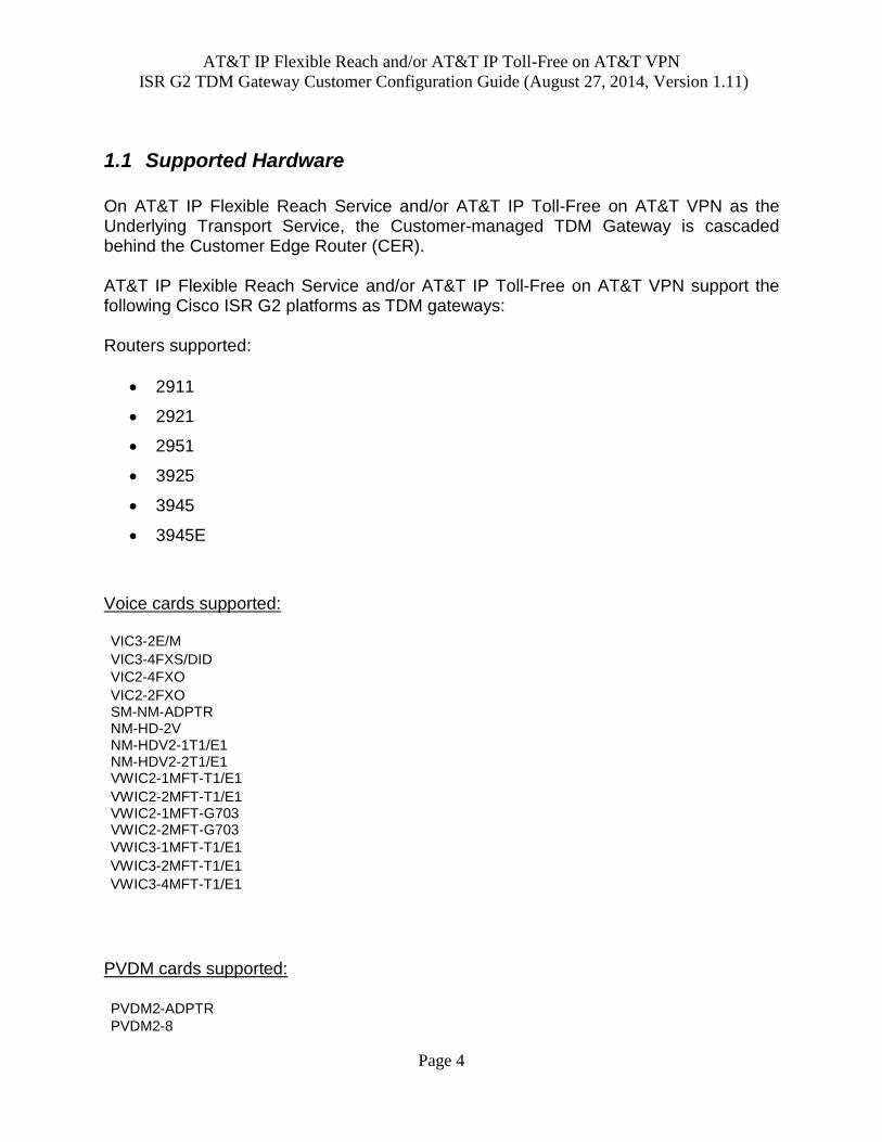
On AT&T IP Flexible Reach Service and/or AT&T IP Toll-Free on AT&T VPN as the Underlying Transport Service, the Customer-managed TDM Gateway is cascaded behind the Customer Edge Router (CER). AT&T IP Flexible Reach Service and/or AT&T IP Toll-Free on AT&T VPN support the following Cisco ISR G2 platforms as TDM gateways: Routers supported:
Configurations in this guide were tested with Cisco IOS 15.2(1)T2ES and 15.3(3)M1ES.
The IOS files can be obtained from: https://upload.cisco.com/cgi-bin/swc/fileexg/main.cgi?CONTYPES=ATT-Managed-Services Note: CCO access is required to download these files.
2900 routers:
c2900-universalk9-mz.SSA-eng-sp-152-1.T2ES
c2900-universalk9-mz.SSA-eng-sp-153-3.M1.bin 2951 router (only supported with 15.3(3)M1ES):
c2951-universalk9-mz.SSA-eng-sp-153-3.M1.bin
3925/45 routers:
c3900-universalk9-mz.SSA-eng-sp-152-1.T2ES
c3900-universalk9-mz.SSA-eng-sp-153-3.M1.bin
3945E router:
c3900e-universalk9-mz.SSA-eng-sp-152-1.T2ES
c3900e-universalk9-mz.SSA-eng-sp-153-3.M1.bin
TDM Gateway will require the UC (Unified Communications) Technology Package License.
2 TDM Gateway Configurations The following section illustrates a sample network topology diagram for sites with a TDM Gateway.
AT&T BVoIP on AT&T VPN site
with VPN CSU-Probe, CER with combined TDM Gateway Router
(CPE site design – physical view)
TDM PBX
phone#2
AT&T VPN CSU-Probe - optional
(managed by AT&T)
TDM PBX
phone#1
WAN
connection
CER with
combined TDM
Gateway
Traditional
PBX
T1
ca
ble
2.1 Types of Voice Ports on the TDM Gateway
Voice ports are found at the intersection of packet-based networks and traditional telephony networks, and facilitate the passing of voice and call signals between the two networks. Physically, voice ports connect a router to a line from a circuit-switched telephony device in a PBX or the PSTN.
Digital trunking can be accomplished via different signaling types: 1) CAS - Channel Associated Signaling “Robbed Bit Signaling”. T1 uses in-band signaling based on either Super-Frames (bits 6 & 12) or Extended Super-frames (bits 6,12,18 & 24).
AT&T IP Flexible Reach and/or AT&T IP Toll-Free on AT&T VPN
2) PRI (U.S.) – Primary Rate Interface; QSIG/CCS (Most of World) – QSIG/Common Channel Signaling. Each of these types will change the available number of channels on the T1 based on the number of channels needed to support the signaling. Alternatively, if no PBX exists, specific ports on the TDM Gateway router can be directly attached to analog devices (telephones or Fax machines) via FXS or FXO ports. The following Cisco link provides additional information on how to configure voice ports:
2.2 Information on Digital Signal Processors (DSP)
DSPs are necessary for packet Telephony technologies such as AT&T IP Flexible Reach Service and/or AT&T IP Toll-Free on AT&T VPN. You will need to purchase the properly sized Packet Voice DSP Modules (PVDM) which contain DSP’s. In order to determine the correct PVDM, you will need to know the number of channels and the codec used.
The ISR G2’s support both PVDM2-X and PVDM3-X series modules.
The following are unique characteristics of PVDM3-X:
The PVDM3 can only be installed on the motherboard of the 29xx or 39xx platform. They cannot
be installed on the NM-HDV2 NM.
The PVDM3-X and PVDM2-X can coexist on the same chassis as long as they are not installed
in the same domain (i.e. Motherboard or NM-HDV2).
The PVDM3s can support a maximum of 64 G711 participants per conference session on any
PVDM3-X and maximum of 16 G729 participants per PVDM3-16 and a maximum of 32 G729
participants per PVDM2-32 and above per conference session.
The following are the characteristics of PVDM2-X with ISR G2:
The ISR G2 motherboard domain can contain either all PVDM2 modules or all PVDM3 modules.
If a mix of PVDM2s and PVDM3s are detected on the motherboard slots, then the PVDM2s will
be deactivated, allowing only the PVDM3s to be used actively
PVDM2-X module requires a special adaptor cards (PVDM2- ADPTR) to be installed on the
motherboard.
The ISR G2 service module can take an NM-HDV2 with PVDM2-X modules using the network-
Note: G729 is a medium complexity codec and G.711 is a high complexity codec.
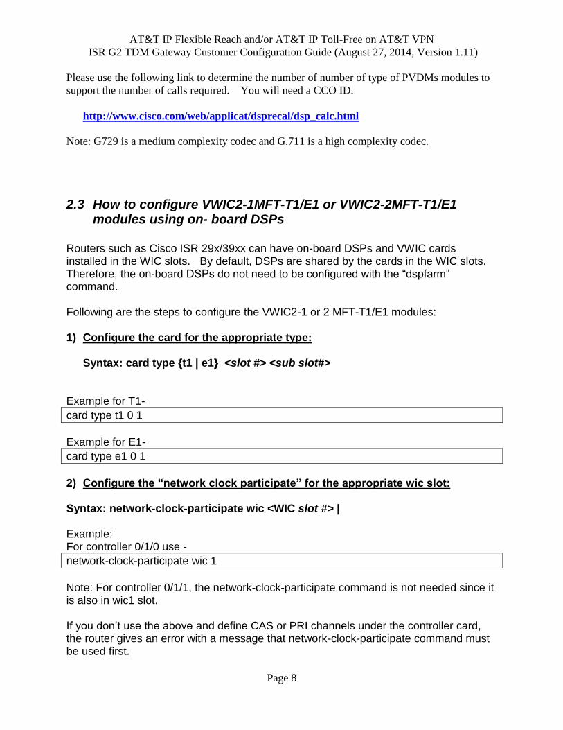
2.3 How to configure VWIC2-1MFT-T1/E1 or VWIC2-2MFT-T1/E1 modules using on- board DSPs
Routers such as Cisco ISR 29x/39xx can have on-board DSPs and VWIC cards installed in the WIC slots. By default, DSPs are shared by the cards in the WIC slots. Therefore, the on-board DSPs do not need to be configured with the “dspfarm” command. Following are the steps to configure the VWIC2-1 or 2 MFT-T1/E1 modules: 1) Configure the card for the appropriate type:
Syntax: card type {t1 | e1} <slot #> <sub slot#>
Example for T1-
card type t1 0 1
Example for E1-
card type e1 0 1
2) Configure the “network clock participate” for the appropriate wic slot: Syntax: network-clock-participate wic <WIC slot #> | Example: For controller 0/1/0 use -
network-clock-participate wic 1
Note: For controller 0/1/1, the network-clock-participate command is not needed since it is also in wic1 slot. If you don’t use the above and define CAS or PRI channels under the controller card, the router gives an error with a message that network-clock-participate command must be used first.
3) Configure the “network clock select”: Specifiy a controller card to use for clocking. Syntax: network-clock-select 1 <T1 or E1> <0>/<WIC slot>/<port> Example:
network-clock-select 1 T1 0/1/0
4) If dual port controller is used, set “clock source internal”: For a dual port controller card, set the clocking internal on the 2nd port. Example:
controller T1 0/1/1 clock source internal
5) Configure the channels under the controller card: Depending on the interface to the PBX being CAS or PRI, the following commands are used: CAS Syntax: ds0-group <ds0-group#> timeslots <time slot range> type <switch type> PRI Syntax: pri-group timeslots <time slot range> <D channel> Example of T1 CAS with 12 channels:
controller T1 2/0 ds0-group 0 timeslots 1-12 type e&m-wink-start
Note: Be sure to set the proper CAS switch type to match the PBX. Choices are:
e&m-delay-dial E & M Delay Dial
e&m-fgd E & M Type II FGD
e&m-immediate-start E & M Immediate Start
e&m-lmr E & M land mobil radio
e&m-melcas-delay MEL CAS (CEPT) E & M Delay Start
e&m-melcas-immed MEL CAS (CEPT) E & M Immediate Start
e&m-melcas-wink MEL CAS (CEPT) E & M Wink Start
AT&T IP Flexible Reach and/or AT&T IP Toll-Free on AT&T VPN
1) Recommended Method: DSP resources can be installed in the PVDM banks directly on
the NM-HDV2 circuit board. No additional router configuration is required for the NM-
HDV2 to use these resources.
2) The NM-HDV2 card can acquire global DSP resources from the on-board PVDMs
(installed on the router’s mother board). The “dspfarm” command must be configured on
the router to allow for the DSP resources to be shared.
3) DSP resources can be acquired from a combination of on-board PVDMs and from the
local PVDMs on the NM-HDV2 card. Take for example, a Cisco 2821 with a NM-
HDV2-2E1 with a PDVM2-64 (30 medium complexity calls) and an on-board PDVM2-
48 (24 calls). By default 30 calls can be supported on the first E1 port. To support the
additional 24 calls, the on-board DSP's need to be shared by explicitly configuring the
dspfarm command.
Steps to configure NM-HDV2-1 or 2T1/E1 with on-board DSPs: The NM-HDV2-1 or 2 E1/T1 card needs to be defined with the type of either E1 or T1, before channels can be defined on a particular trunk. To change the definition from e1 to t1, enter “no card type e1 1 1”, save and reload and reconfigure. 1) Define card type
Syntax: card type {t1 | e1} <slot #> <subslot #>
Example:
card type e1 1 1
2) Configure “dspfarm” for NM-HDV2 to use global DSP resources.
voice-card 0 dspfarm
3) Configure the “network clock participate” for the appropriate slot: Syntax: network-clock-participate slot <slot #> Example: For controller E1 1/0 use:
network-clock-participate slot 1
Note: For controller 1/1 , the network-clock-participate command is not needed since it is also in slot 1.
AT&T IP Flexible Reach and/or AT&T IP Toll-Free on AT&T VPN
If you don’t use the above and define CAS or PRI channels under the controller card, the router gives an error with a message that network-clock-participate command must be used first. 4) Configure the “network clock select”: Syntax: network-clock-select 1 <T1 or E1> <slot#>/port#> Specifiy a controller card to use for clocking. Example:
network-clock-select 1 T1 1/0
5) If dual port controller is used, set “clock source internal”: For a dual port controller card, set the clocking internal on the 2nd port. Example:
controller T1 1/1 clock source internal
6) Configure the channels under the controller card: Depending on the interface to the PBX being CAS or PRI, the following commands are used. CAS Syntax: ds0-group <ds0-group#> timeslots <time slot range> type <switch type> PRI Syntax: pri-group timeslots <time slot range> <D channel> Example of T1 CAS with 12 channels:
controller T1 1/0 ds0-group 0 timeslots 1-12 type e&m-wink-start
Note: Be sure to set the proper CAS switch type to match the PBX. Choices are:
e&m-delay-dial E & M Delay Dial
e&m-fgd E & M Type II FGD
e&m-immediate-start E & M Immediate Start
e&m-lmr E & M land mobil radio
AT&T IP Flexible Reach and/or AT&T IP Toll-Free on AT&T VPN
interface Serial 1/0:23 isdn switch-type primary-5ess ! voice-port 1/0:23 !
Note: Be sure to set the proper PRI switch type to match the PBX. Choices are:
primary-4ess Lucent 4ESS switch type for the U.S.
primary-5ess Lucent 5ESS switch type for the U.S.
primary-dms100 Northern Telecom DMS-100 switch type for the U.S.
primary-dpnss DPNSS switch type for Europe
primary-net5 NET5 switch type for UK, Europe, Asia and Australia
primary-ni National ISDN Switch type for the U.S.
primary-ni2c The Cisco NAS-SC switchtype based on NI2C.
primary-ntt NTT switch type for Japan
primary-qsig QSIG switch type
primary-ts014 TS014 switch type for Australia (obsolete)
Add an interdigit timeout of 5 seconds:
voice-port 1/0:23 timeouts interdigit 5
Example: For a 2921 router connecting to a PRI port on a PBX with an on-board PDVM2-64 DSP cards and NM-HDV2 card in slot1 without any DSPs. The on-board DSP must be used to be able to define timeslots on the cards.
2921#sho run Building configuration... ! version 15.2 service timestamps debug datetime msec service timestamps log datetime msec no service password-encryption ! hostname 2921-1 ! boot-start-marker
AT&T IP Flexible Reach and/or AT&T IP Toll-Free on AT&T VPN
boot system flash:c2900-universalk9-mz.SPA.152-1.T2ES boot-end-marker ! card type e1 1 1 no logging buffered ! network-clock-participate slot 1 !allow use of network clock a a source network-clock-select 1 E1 1/1 ! name source of the network clock ! ! no ipv6 cef ip source-route ip cef ! no ip domain lookup ip domain name yourdomain.com ! voice-card 0 dspfarm ! To allows the NM-HDV module share on-board dsps. … ! controller E1 1/0 shutdown ! controller E1 1/1 pri-group timeslots 1-10,16 ! interface Serial1/1/:15 no ip address encapsulation hdlc isdn switch-type primary-5ess isdn protocol-emulate network isdn incoming-voice voice no cdp enable ! voice-port 0/1/0:15 timeouts interdigit 5
2.5 Configuring Analog Voice Ports
Analog voice ports do not require as much configuration as digital ports. It is recommended to configure each port with a station-id name and its corresponding
AT&T IP Flexible Reach and/or AT&T IP Toll-Free on AT&T VPN
station-id number (aka phone number, DID). It is recommended to put DSPs on the motherboard when using analog ports.
Sample analog port configuration (FXS port) :
voice-port 0/3/0
timeouts interdigit 5
station-id name George
station-id number 12013982000
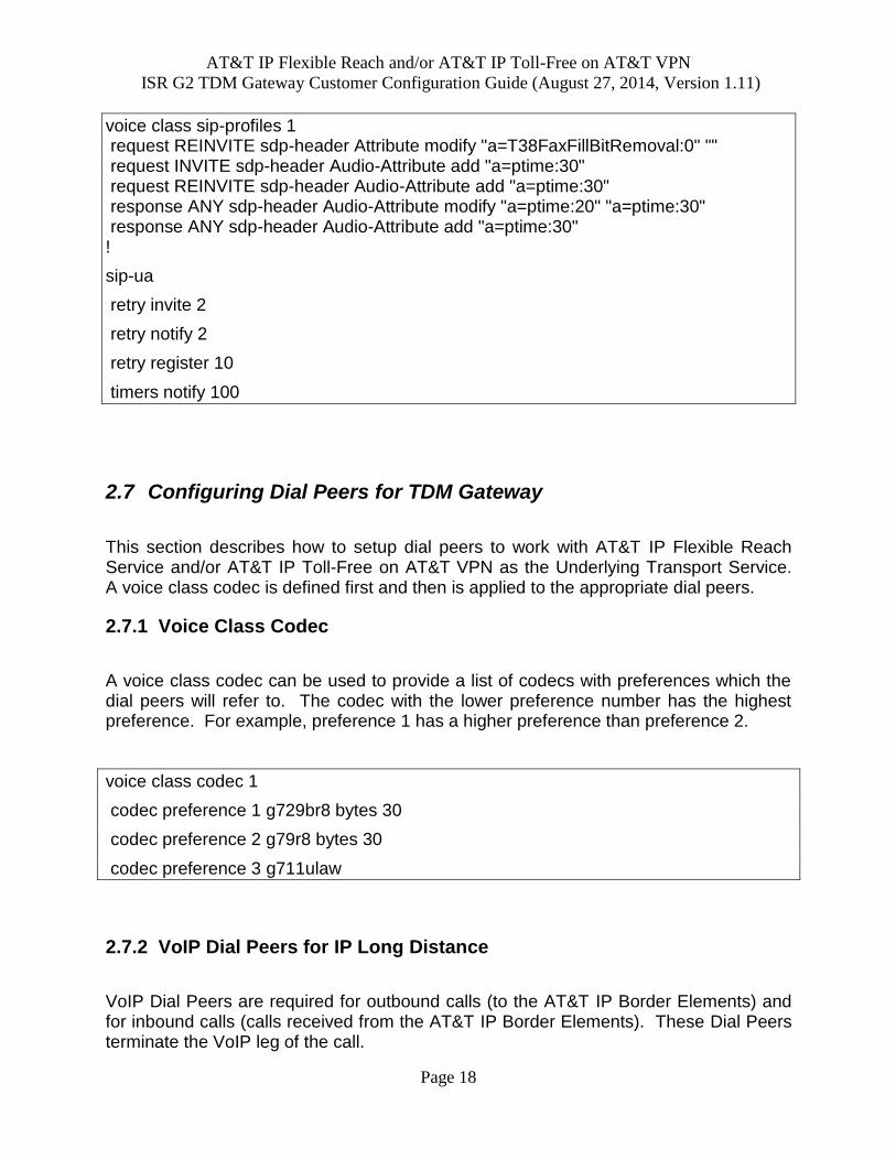
2.6 Configuring SIP for TDM PBX
The following configuration is required to configure a router for SIP signaling for use with the AT&T IP Border Elements. A loopback interface must be configured on the TDM Gateway. The loopback interface must configured with either the AT&T provided or customer supplied AT&T signaling IP address. If AT&T provided, this address can be found in the “Customer Router Configuration and VQM Shipping Confirmation” letter and is referenced as the IP signaling address. In the following sample router configuration, the loopback 0 interface has been configured with the signaling IP address of 12.23.44.27.
This section describes how to setup dial peers to work with AT&T IP Flexible Reach Service and/or AT&T IP Toll-Free on AT&T VPN as the Underlying Transport Service. A voice class codec is defined first and then is applied to the appropriate dial peers.
2.7.1 Voice Class Codec
A voice class codec can be used to provide a list of codecs with preferences which the dial peers will refer to. The codec with the lower preference number has the highest preference. For example, preference 1 has a higher preference than preference 2.
voice class codec 1
codec preference 1 g729br8 bytes 30
codec preference 2 g79r8 bytes 30
codec preference 3 g711ulaw
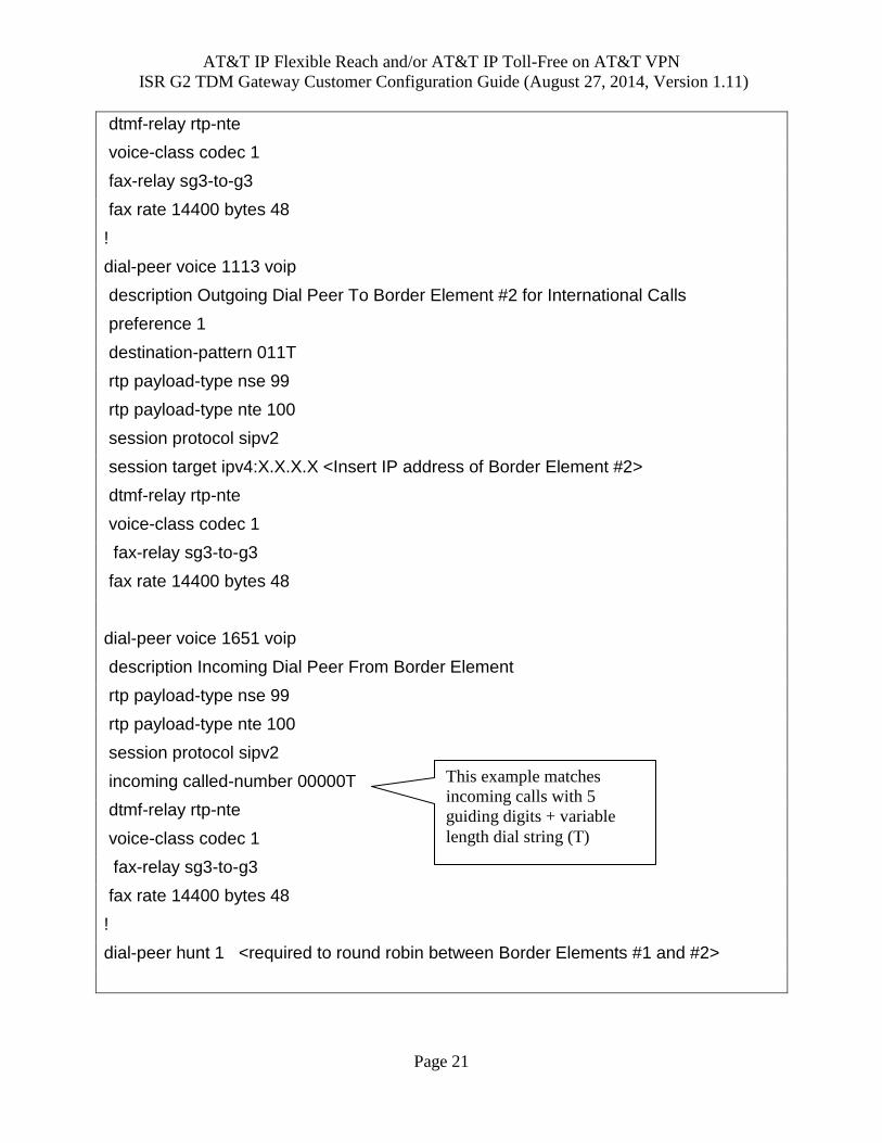
2.7.2 VoIP Dial Peers for IP Long Distance
VoIP Dial Peers are required for outbound calls (to the AT&T IP Border Elements) and for inbound calls (calls received from the AT&T IP Border Elements). These Dial Peers terminate the VoIP leg of the call.
AT&T IP Flexible Reach and/or AT&T IP Toll-Free on AT&T VPN
Incoming calls from the AT&T IP Border Element (IPBE) will use the following digit format:
5 zeros for guiding digits + pbx extension prefix (optional up to 6 digits) + desired number of phone digits
Additional Notes: 21 is the total number of digits that the network can deliver to the router. The
number of guiding digits + number of PBX extension digits + number of desired phone digits must be less than or equal to 21
For wildcard dialing, guiding digits will not be signaled. The desired number of digits is decided by the PBX extension length.
Following is an example of the digits forwarded by the AT&T IP Border Element with a 7 digit extension:
000004912234 (5 zeros for guiding digits + 7 digit extension)
The incoming dial peer must be configured to match the digits sent by the AT&T IPBE.
If unsure of the format of the digits coming in from the AT&T IPBE, turn on the “debug ccapi inout” command on the router and initiate an inbound call. (Note: It is recommended to turn on debugs during off hours). With this debug, it is possible to view the digits that the AT&T IPBE is sending. This debug will also show if Dial Peers are matching on those digits. Two Dial Peers should be matched. The first should be a VoIP dial peer (to properly terminate the call) and the second is a POTS dial peer (which points to the appropriate digital/analog port).
The AT&T IPBE addresses to be configured in the dial peers, can be obtained from the “Customer Router Configuration and VQM Shipping Confirmation” letter and is referenced as the AT&T IPBE addresses.
If a customer needs to enable compressed RTP (cRTP), it is required to configure “no vad” under all VoIP dial peers (outgoing and incoming dial peers). By default, the VAD (Voice Activity Detection) is enabled on all dial peers.
Example configuration:
dial-peer voice 1110 voip
description Outgoing Dial Peer To Border Element #1 for US calls
AT&T IP Flexible Reach and/or AT&T IP Toll-Free on AT&T VPN
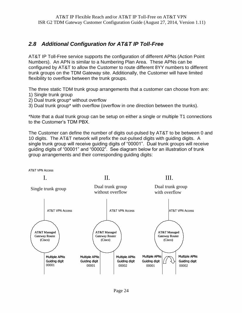
2.8 Additional Configuration for AT&T IP Toll-Free
AT&T IP Toll-Free service supports the configuration of different APNs (Action Point Numbers). An APN is similar to a Numbering Plan Area. These APNs can be configured by AT&T to allow the Customer to route different 8YY numbers to different trunk groups on the TDM Gateway site. Additionally, the Customer will have limited flexibility to overflow between the trunk groups. The three static TDM trunk group arrangements that a customer can choose from are: 1) Single trunk group 2) Dual trunk group* without overflow 3) Dual trunk group* with overflow (overflow in one direction between the trunks). *Note that a dual trunk group can be setup on either a single or multiple T1 connections to the Customer’s TDM PBX. The Customer can define the number of digits out-pulsed by AT&T to be between 0 and 10 digits. The AT&T network will prefix the out-pulsed digits with guiding digits. A single trunk group will receive guiding digits of “00001”. Dual trunk groups will receive guiding digits of “00001” and “00002”. See diagram below for an illustration of trunk group arrangements and their corresponding guiding digits: AT&T VPN Access
Codecs supported for AT&T IP Toll-Free service on AT&T VPN service include:
g729br8 bytes 30
g79r8 bytes 30
g711ulaw
It is recommended to configure a “voice-class codec” to the voip dial peers as described in section 2.9.1.
2.8.1 Single Trunk Group Configuration
The following incoming dial peers must be added to the router’s TDM Gateway configuration for AT&T IP Toll-Free service. As previously stated, a single trunk group configuration will send guiding digits of “00001”. Therefore, dial-peer voice 1501 is added in the following sample configuration to match on those guiding digits. These configurations assume the CAS and PRI configurations are already in place (see sections 2.5 and 2.6). Sample Configuration for Single Trunk Group Configuration
dial-peer voice 1501 voip description Incoming Dial Peer From Border Element rtp payload-type nse 99 rtp payload-type nte 100 session protocol sipv2 incoming called-number 00001T dtmf-relay rtp-nte voice-class codec 1 fax-relay sg3-to-g3 fax rate 14400 bytes 48 ! dial-peer voice 1650 pots destination-pattern 00001T port 0/1/0:0 **Points to the appropriate voice port – CAS or PRI**!
2.8.2 Dual Trunk Group
With the dual trunk group option, the AT&T network can send incoming calls with guiding digits of 00001 or 00002. An example of incoming call digits could be
AT&T IP Flexible Reach and/or AT&T IP Toll-Free on AT&T VPN
000019143975000 or 000029143976000. The router can handle the calls differently based on these incoming digits. Note that in all dual trunk group sample configurations shown, the dial peer 1501 is added to match on guiding digits of “00001” and “00002”. The customer can choose between dual trunk groups without overflow or with overflow. The following examples will illustrate how to configure these two options with CAS and PRI ports.
2.8.2.1 Dual Trunk Group Without Overflow
This sample configuration is for a single T1 CAS to the customer PBX with 2 trunk groups. Trunk Group 1 has 10 channels and Trunk Group 2 has 14 channels. Sample Configuration for Dual Trunk Group without Overflow – CAS port
controller T1 0/1/0
framing esf
linecode b8zs
ds0-group 0 timeslots 1-10 type e&m-wink-start ! 10 channels in one trunk group
ds0-group 1 timeslots 11-24 type e&m-wink-start ! 14 channel in 2nd trunk group
!
!
voice-port 0/1/0:0
timeouts interdigit 2
music-threshold -70
busyout monitor Serial0/0/0
!
voice-port 0/1/0:1
timeouts interdigit 2
music-threshold -70
busyout monitor Serial0/0/0
!
!
dial-peer voice 1501 voip
description Incoming Dial Peer From Border Element – Trunk Group 1 & 2
rtp payload-type nse 99
rtp payload-type nte 100
session protocol sipv2
incoming called-number 0000[1,2]T
dtmf-relay rtp-nte
voice-class codec 1
fax-relay sg3-to-g3
fax rate 14400 bytes 48
!
Trunk Group 1
Trunk Group 2
AT&T IP Flexible Reach and/or AT&T IP Toll-Free on AT&T VPN
In the dual trunk group with overflow setup, if the first trunk group is fully used, the next incoming call will terminate on the channels assigned to second trunk group. The following sample configuration illustrates how to setup dual trunk with overflow on a CAS port. In this setup, the customer is using CAS signaling and has 10 channels in trunk group 1 and 14 channels in trunk group 2. The trunk group called TG-Two (Trunk Group Two) will overflow into channels defined for TG-One. Sample Configuration for Dual Trunk Group with overflow – CAS port
controller T1 0/1/0
framing esf
linecode b8zs
ds0-group 0 timeslots 1-10 type e&m-wink-start *** 10 channels in Trunk Group 1***
ds0-group 1 timeslots 11-24 type e&m-wink-start ***14 channel in Trunk Group 2***
!
!
voice-port 0/1/0:0
timeouts interdigit 2
music-threshold -70
trunk-group TG-One
!
voice-port 0/1/0:1
timeouts interdigit 2
music-threshold -70
trunk-group TG-Two
!
! Then we have 2 inbound pots (from the PBX) dial peers – one for each trunk group
!
dial-peer voice 1501 voip
description Incoming Dial Peer From Border Element – Trunk Group 1 & 2
rtp payload-type nse 99
rtp payload-type nte 100
session protocol sipv2
incoming called-number 0000[1,2]T
dtmf-relay rtp-nte
voice-class codec 1
Trunk Group 1
Trunk Group 2
AT&T IP Flexible Reach and/or AT&T IP Toll-Free on AT&T VPN
The following sample configuration illustrates how to setup dual trunk with overflow on a PRI port. In this setup, the Customer is using T1 port with PRI signaling and has 21 channels in trunk group 1 and 2 channels in trunk group 2. The trunk group called TG-Two will overflow into channels defined for TG-One. Sample Configuration of Dual Trunk Group with Overflow – PRI port:
trunk group TG-One
description "IP Toll-Free DS0s - Critical Use"
hunt-scheme least-used
!
trunk group TG-Two
description "IP Toll-Free DS0s - Normal Use"
hunt-scheme least-used
!
controller T1 0/1/0
pri-group timeslots 1-24
trunk-group TG-One timeslots 1-21
trunk-group TG-Two timeslots 22-23
!
voice-port 0/1/0:23
music-threshold -70
busyout monitor Serial 0/0/0
busyout action shutdown
!
dial-peer voice 1501 voip
description Incoming Dial Peer From Border Element – Trunk Group 1 & 2
rtp payload-type nse 99
rtp payload-type nte 100
session protocol sipv2
incoming called-number 0000[1,2]T
dtmf-relay rtp-nte
T1 PRI port configured into two trunk group
based on timeslots.
This dial peer configured to match on guiding
digits of 00001. Points to Trunk Group 1 only.
This dial peer configured to match on guiding
digits of 00002 only. Points to both Trunk
Group One and Two (used for overflow).
AT&T IP Flexible Reach and/or AT&T IP Toll-Free on AT&T VPN
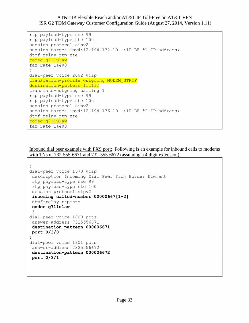
Inbound dial peer example with T1 PRI port: Following is an example for inbound calls to
modems with a TN range of 732-555-4410 and 732-555-4419 (assuming a 4 digit extension).
dial-peer voice 1670 voip
description Incoming Dial Peer From Border Element
rtp payload-type nse 99
rtp payload-type nte 100
session protocol sipv2
incoming called-number 00000441.
dtmf-relay rtp-nte
codec g711ulaw
!
dial-peer voice 1671 pots
description Dial Peer for T1 digital port
destination-pattern 00000441.
forward-digits 4
port 0/1/0:15
Note: When adding new inbound/outbound modem TNs to an existing configuration: Outbound
dial peers may need to be updated when new outbound dialed TNs are added if not already
covered by existing outbound dial peer configuration. Inbound dial peers may also need to be
updated when new modem TNs are added to the IP Flexible Reach site if not already covered by
existing inbound dial peer configuration. Please make sure to check the existing dial peers to
determine if additional configuration needs to be applied to the router.
2.11 Routing
For routing configuration for the combined CER and TDM Gateway solution, please refer to Chapter 5 in the Customer Edge Router (CER) Customer Configuration Guide for AT&T IP Flexible Reach Service and/or AT&T IP Toll-Free on AT&T VPN as the Underlying Transport Service. http://www.corp.att.com/bvoip/avpn/implementation/ (login: att, password: attvoip).
2.12 Configuring Call Detail Records (CDR) Collection
Following are the commands to configure CDR collection in the TDM Gateway.
The proper key will need to be entered (provided by AT&T in the Customer Router Configuration for
Customer-Managed Router and TDM PBX Letter).
aaa new-model aaa group server radius h323 server 135.89.102.66 auth-port 1812 acct-port 1813
This Customer Configuration Guide ("CCG") is offered as a convenience to AT&T's
customers. The specifications and information regarding the product in this CCG are
subject to change without notice. All statements, information, and recommendations in
this CCG are believed to be accurate but are presented without warranty of any kind,
express or implied, and are provided “AS IS”. Users must take full responsibility for the
application of the specifications and information in this CCG.
In no event shall AT&T or its suppliers be liable for any indirect, special, consequential, or incidental damages, including, without limitation, lost profits or loss or damage arising out of the use or inability to use this CCG, even if AT&T or its suppliers have been advised of the possibility of such damage.