73
TDMA Tutorial
TDMA Tutorial
Outline of Presentation
• Evolution of Technology– AMPS to TDMA
• The TDMA Digital Control Channel– Features and capabilities– Technical description
• Services and design examples

TDMA Standards Overview
• EIA 553– Analog AMPS-based technology platform
• IS-54B– Introduces a TDMA digital traffic channel
and a new feature set• authentication, calling number ID, message
waiting indicator, and voice privacy.
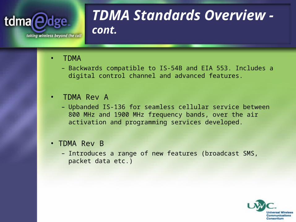
TDMA Standards Overview - cont.
• TDMA– Backwards compatible to IS-54B and EIA 553. Includes a digital
control channel and advanced features.
• TDMA Rev A– Upbanded IS-136 for seamless cellular service between 800 MHz and
1900 MHz frequency bands, over the air activation and programming services developed.
• TDMA Rev B– Introduces a range of new features (broadcast SMS, packet data etc.)
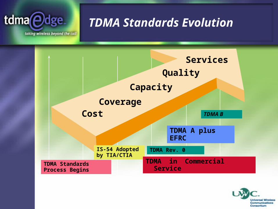
TDMA Standards Evolution
1988 1990 1992 1994 1996 1998
Capacity
Services
Quality
CoverageCost
TDMA Standards Process Begins
IS-54 Adopted by TIA/CTIA
TDMA in Commercial Service
TDMA Rev. 0
TDMA A plusEFRC
TDMA B

TDMA Traffic Channel Structure
• Modulation– /4 DQPSK - differential quadrature phase shift keying.
– Across air bit rate = 48.6 Kbps.
• Frame Structure– TDMA frame = 40mS.– Six 6.67 ms slots per frame, two slots used for full rate voice.
TDMA Slot Format
Sync SACCH Data CDVCC Data RSVD
TDMA Frame
40 ms

TDMA Speech Coding
• Speech and channel coding are important factors in good voice quality. Other factors include:
– System planning (handoff, reuse, coverage, etc.)– Handset design– Echo suppression, audio balancing, …
• Two speech codecs defined for TDMA– VSELP - Vector Sum Excited Linear Predictive – ACELP - Algebraic Code Excited Linear Predictive
• VSELP– Originally defined for IS-54B - 80s Technology
• ACELP– Newly defined for TDMA - 90s Technology - “state of the art”– Offers wireline voice quality in clean conditions
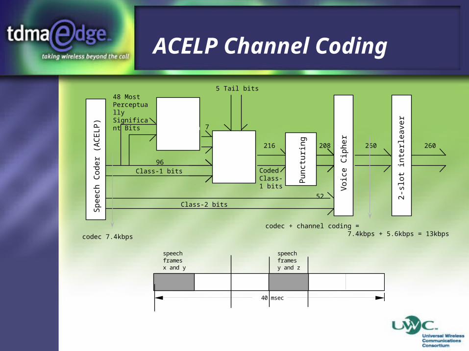
ACELP Channel Coding
Class-2 bits
Class-1 bits96
7
208
52
260260216
Coded Class-1 bits
5 Tail bits
7-bit CRCComputation
Rate 1/2 Convolutional Coding
48 Most Perceptually Significant Bits
Sp
ee
ch C
od
er
(AC
EL
P)
Pu
nct
urin
g
Vo
ice
Cip
he
r
2-s
lot
inte
rlea
ver
codec 7.4kbps
codec + channel coding = 7.4kbps + 5.6kbps = 13kbps
40 msec
speech frames x and y
speech frames y and z
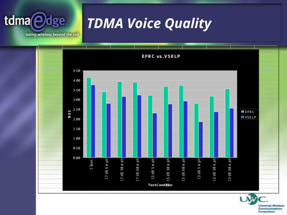
TDMA Voice Quality
EFRC vs. VSELP
0.00
0.50
1.00
1.50
2.00
2.50
3.00
3.50
4.00
4.50
Cle
an
17 d
B 5
mph
17 d
B 3
0 m
ph
17 d
B 6
0 m
ph
15 d
B 5
mph
15 d
B 3
0 m
ph
15 d
B 6
0 m
ph
13 d
B 5
mph
13 d
B 3
0 m
ph
13 d
B 6
0 m
ph
Test Condition
MO
S EFRC
VSELP

Mobile Assisted Handoff (MAHO)
• System instructs mobile to measure neighbor channels.
• Results reported back to system to aid handoff decision.
• Designed to decrease dropped calls and improve handoffs.
• TDMA supports any combination of handoff between digital and analog channels.
• TDMA also supports handoff between 800 MHz and 1900 MHz cellular bands.
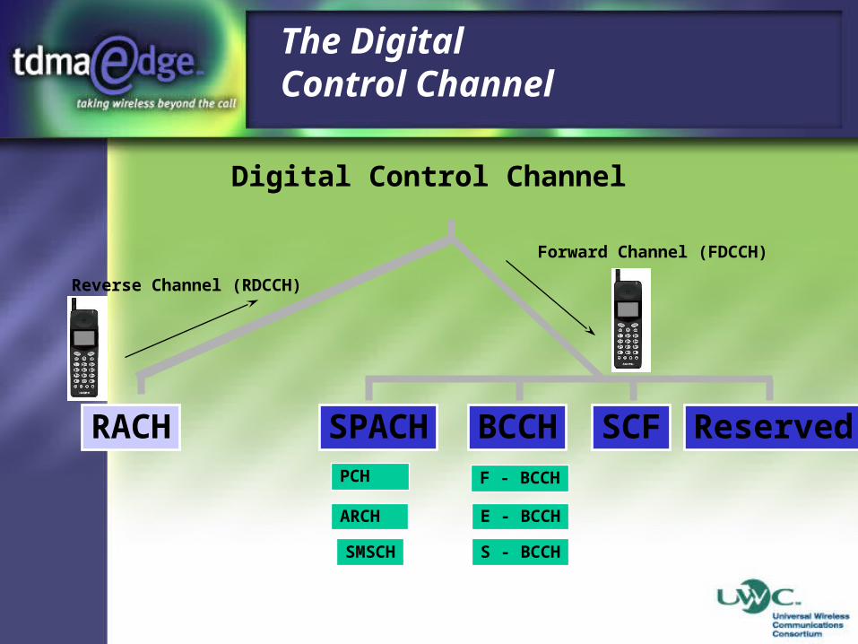
The Digital Control Channel
RACH SPACH BCCH SCF ReservedPCH
ARCH
SMSCH
F - BCCH
E - BCCH
S - BCCH
Digital Control Channel
Reverse Channel (RDCCH)
Forward Channel (FDCCH)
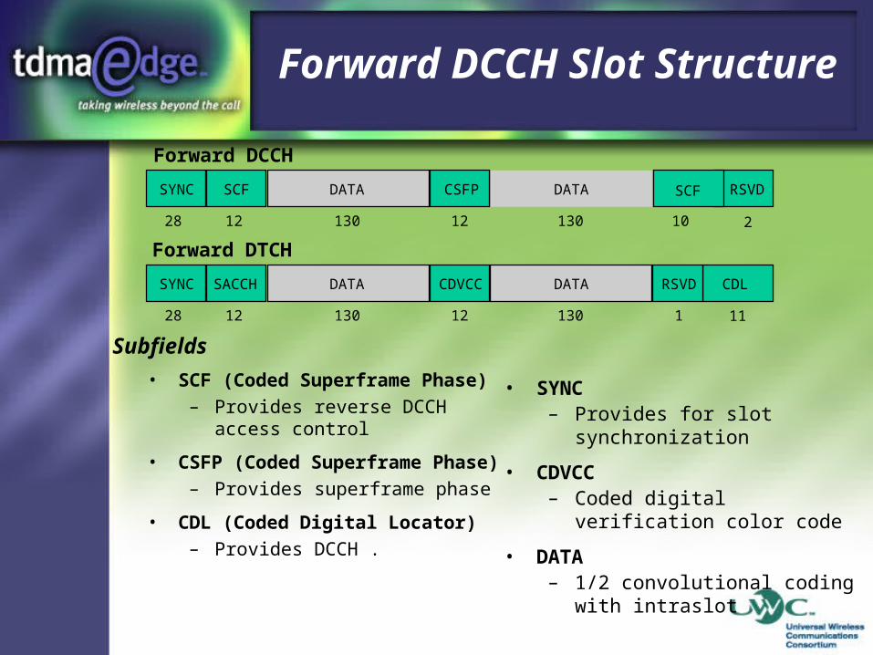
Forward DCCH Slot Structure
• SCF (Coded Superframe Phase)– Provides reverse DCCH access
control
• CSFP (Coded Superframe Phase)– Provides superframe phase
• CDL (Coded Digital Locator)– Provides DCCH .
• SYNC– Provides for slot synchronization
• CDVCC – Coded digital verification color
code
• DATA – 1/2 convolutional coding with
intraslot interleaving
SYNC SCF DATA SCF RSVDDATACSFP
28 130 130 10 212 12
Forward DCCH
SYNC SACCH DATA RSVD CDLDATACDVCC
28 130 130 1 1112 12
Forward DTCH
Subfields

Superframe Formation
TimeSlot
1
TimeSlot
2
TimeSlot
3
TimeSlot
4
TimeSlot
5
TimeSlot
6
TimeSlot
1
TimeSlot
2
TimeSlot
3
TimeSlot
4
TimeSlot
5
TimeSlot
6
Superframe - 32 slots (0.64 sec duration)
TimeSlot
1
TDMA Frame
TDMA Block
SFP= 0
SFP= 1
SFP= 2
SFP= 3
SFP= 4
SFP= 5
SFP= 6
SFP= 7
SFP= 8
SFP= 9
SFP= 30
SFP= 31

Superframe Composition
F-BCCH E-BCCH S-BCCH SPACH
F E S S... ... ...........
SFP 0 31
One Superframe = 16 TDMA frames = 640ms
... S
F-BCCH “Fast Broadcast Channel”
- Messages repeat every superframe
- Messages contain information critical for service on DCCH
E-BCCH “Extended Broadcast Channel”- Messages extended over multiple
superframes- Messages less time critical
S-BCCH “SMS Broadcast Channel”- Reserved for Broadcast SMS (IS-136B)
SPACH “SMS, Paging, and Access Channel”
- Used for sending Point-to-Point Messages
S

F-BCCH E-BCCH S-BCCH SPACH
F E S S S... ... ...........
0 31
One Superframe
... S
F-BCCH E-BCCH S-BCCH SPACH
F E S S S... ... ...........
0 31
One Superframe
... S
One Hyperframe = Two Superframes = 1.28s
The SPACH “SMS, Paging, and Access Channel”- Page messages (PCH)
- PCH messages are always repeated in secondary superframe- Access Response Messages (ARCH)
- ARCH messages are sent in idle SPACH slots (i.e. no page messages)- ARCH message may be sent over multiple superframes
- Teleservices messages (SMSCH)- SMSCH message are sent in idle SPACH slots- SMSCH message may be sent over multiple superframes
Superframes and Hyperframes
Sleepmode
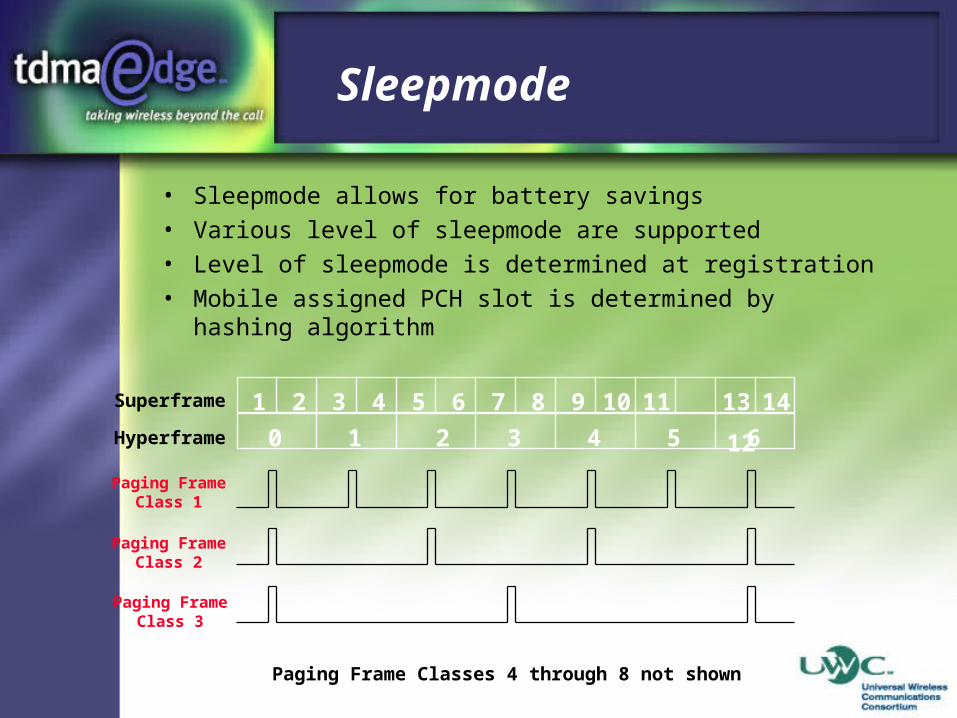
• Sleepmode allows for battery savings• Various level of sleepmode are supported• Level of sleepmode is determined at registration• Mobile assigned PCH slot is determined by hashing
algorithm
0 1 2 3 4 5 6
1 2 3 4 5 6 7 8Superframe
Hyperframe
Paging FrameClass 1
Paging FrameClass 3
Paging FrameClass 2
9 10 11
12
13 14
Paging Frame Classes 4 through 8 not shown
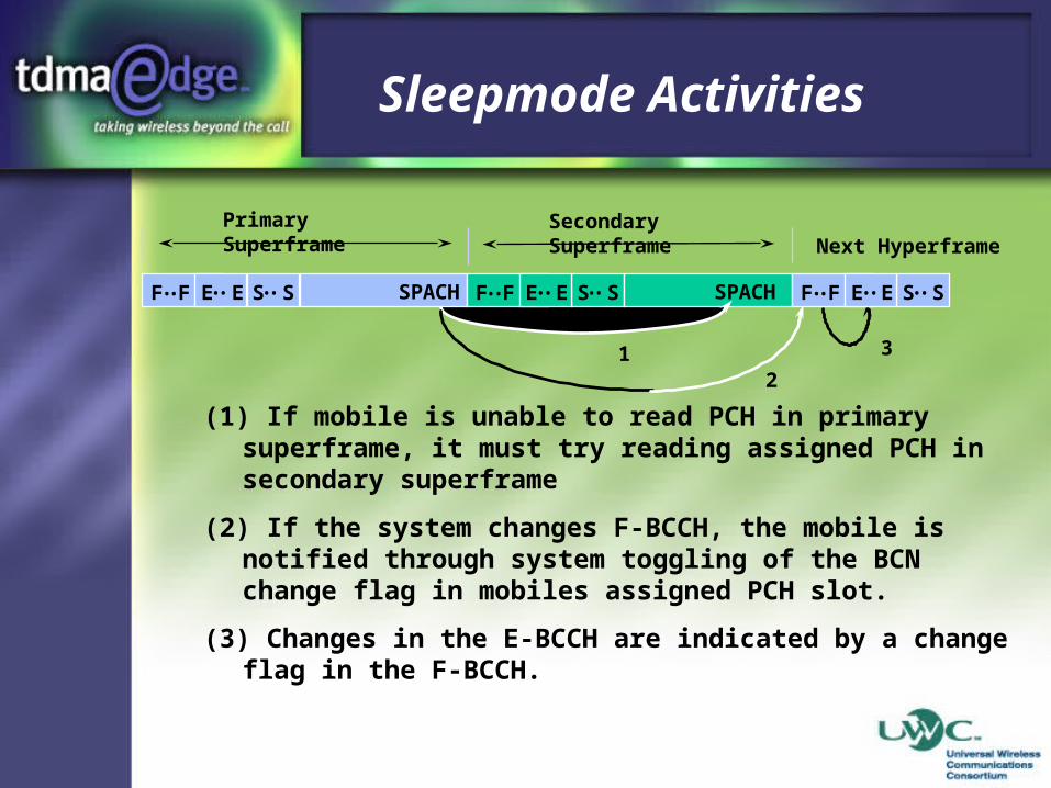
(1) If mobile is unable to read PCH in primary superframe, it must try reading assigned PCH in secondary superframe
(2) If the system changes F-BCCH, the mobile is notified through system toggling of the BCN change flag in mobiles assigned PCH slot.
(3) Changes in the E-BCCH are indicated by a change flag in the F-BCCH.
Sleepmode Activities
Primary Superframe Secondary Superframe
12
3
Next Hyperframe
F SPACH..F E.. E S..S F SPACH..F E..E S.. S F..F E..E S..S

Reverse DCCH Slot Structure
6 6 16 28 122 24 122
G R PREAM SYNC SYNC+DATA DATA
Reverse DCCH
6 386 6 16 28 122 24 78
G R PREAM SYNC SYNC+DATA
Abbreviated Reverse DCCH
DATA
R AG
6 6 16 28 122 12 12 122
G R DATA SYNC SACCH CDVCCDATA DATA
Reverse DTC
• Two burst lengths are defined to accommodate both large and small cells
• SYNC+ provides additional synchronization information to the base station.
• PREAM aids base station automatic gain control to reduce signal distortion.
• AG provides 38 bits of guard for the abbreviated burst.
• G and R provides guard and ramp.
R-DCCH Multiple Access
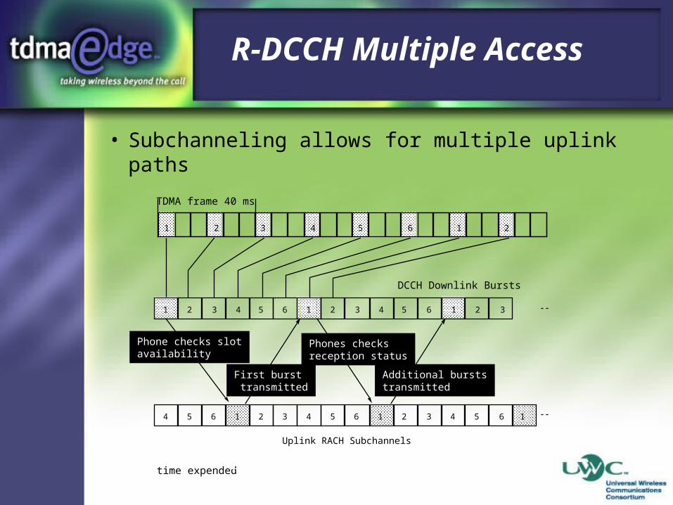
• Subchanneling allows for multiple uplink paths
1 2 3 4 5 6 1 2 3 4 5 6 1 2 3
time expended
Uplink RACH Subchannels
TDMA frame 40 ms
1 2 3 4 5 6 1 2
DCCH Downlink Bursts
4 5 6 1 2 3 4 5 6 1 2 3 4 5 6
Phone checks slotavailability
First burst transmitted
Phones checksreception status
Additional burststransmitted
1
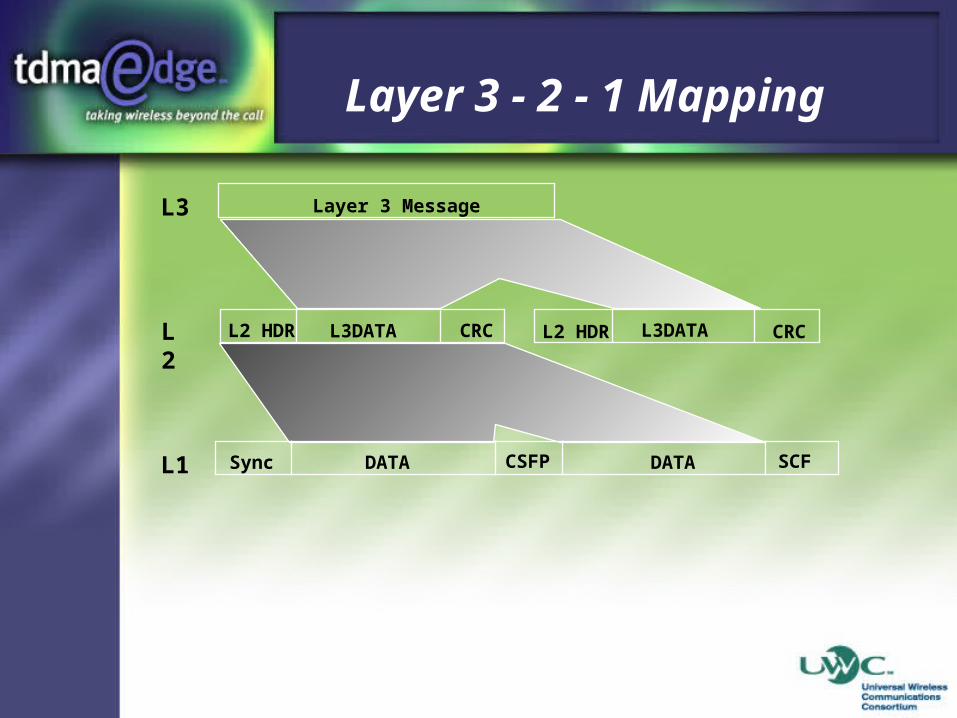
Layer 3 - 2 - 1 Mapping
L3DATA
Layer 3 Message
L2 HDR CRC
L3
L2 L3DATA CRCL2 HDR
Sync DATA DATACSFP SCFL1
DCCH Layer 3 Functionality
• Call processing, registration, and paging
• Mobile assisted channel allocation (MACA)
• Identity structures
• Cell selection
• Cell reselection
• Hierarchical cells
• Tiered services– Private/public systems

Call Processing
• Origination uses the same call model as IS-54B– Phone sends origination message to system on reverse DCCH– Traffic channel designation sent in base station response
• Paging on the DCCH– A phone is allocated a particular SPACH slot which is monitored for pages.– This allocation is based on the MIN of the phone
• Authentication– Same algorithms as used in IS-54B
Paging
• TDMA Paging – No rescan on reverse access channel removes the traditional
system border problems associated with analog.• Mobile responds to pages on the same DCCH as it receives pages on.
– Page message combination supports higher paging capacity• Single word paging uses one L2 frame per page
• Triple hard paging uses one L2 frame per three pages
• Standard allows for even further paging capacity through use of 20 and 24 bit TMSIs
– TDMA registration techniques allow for defining precise paging areas which can further increase messaging capacity.
Registration Types
• DCCH-based registration conditions are defined according to the following order of priority:
– Test registration New to TDMA– Power down – Deregistration New to TDMA– Power up – System transition condition Enhanced in TDMA– Location area (VMLA) New to TDMA– Periodic registration Enhanced in TDMA– ACC to DCCH transition New to TDMA
• The system broadcasts which forms of registration are supported on F-BCCH.

VMLA Registration
110
10
10
5
10
10
4
5
8
4
5
8
44
4
8
9
9
8
99
9
9
5 1
1
RNUM broadcast by cell.
RNUM list sent to mobiles at registration.
Mobile must register when unknown RNUM received.

Aspects of TDMA Registration
• TDMA-Based Registration– Several new registration types are added in TDMA
– Mobiles indicate the registration type they are responding to.
– The nuisance registrations can be reduced
– The registration defined to fully support private, public, and residential systems.
– VMLA-based registration • increases system control over paging load by tracking mobiles
based on location.• eliminates the ping-pong registration problem by defining
overlapping areas.
Through a proper configuration, a TDMA system can result in reduced registration traffic with greater paging efficiency.
Mobile Assisted Channel Allocation (MACA)
• MACA allows the mobile to provide the base station with a channel quality report upon access.
• Channel Quality Report– Long-term measurement - on serving DCCH: a running average over 32 frames
of RSS, WER, and BER.– Short-term measurement - on up to 15 channels specified by base: RSS based
on 4 measurements.
• The base station indicates the specific access types that the mobile is to provide a channel quality report.
• The MACA report can be used by the base station for enhanced channel assignment.
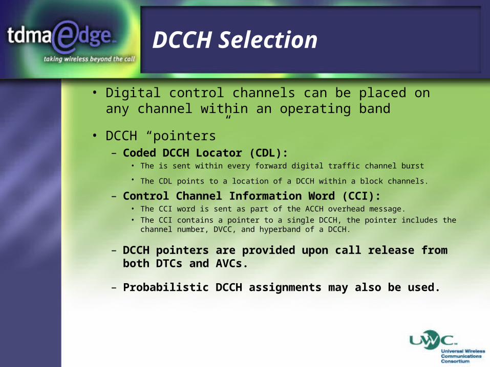
DCCH Selection
• Digital control channels can be placed on any channel within an operating band
• DCCH “pointers”– Coded DCCH Locator (CDL):
• The is sent within every forward digital traffic channel burst
• The CDL points to a location of a DCCH within a block channels. – Control Channel Information Word (CCI):
• The CCI word is sent as part of the ACCH overhead message. • The CCI contains a pointer to a single DCCH, the pointer includes the channel number,
DVCC, and hyperband of a DCCH.
– DCCH pointers are provided upon call release from both DTCs and AVCs.
– Probabilistic DCCH assignments may also be used.
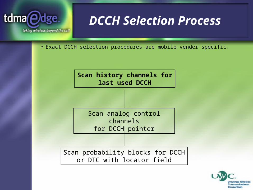
DCCH Selection Process
• Exact DCCH selection procedures are mobile vender specific.
Scan history channels forlast used DCCH
Scan analog control channelsfor DCCH pointer
Scan probability blocks for DCCHor DTC with locator field

Cell Reselection Procedures
• TDMA cell reselection procedures are executed by mobiles while a mobile is in the idle state (i.e., sleepmode).
• Parameters broadcast by the base station gracefully steer mobiles to cells based on:– Mobility– Cell type (underlay or overlay)– Relative and absolute RF thresholds– Received signal strength– Private, public, residential
DCCH Neighbor Lists
• The DCCH neighbor list is central to the cell reselection process.
• Every DCCH broadcasts a neighbor list.
• The DCCH neighbor list provides mobiles with reselection parameters on all neighbor cells and sectors.– Mobiles use this information to choose the appropriate cell based mobility, desired network
type, etc.
• The neighbor list provides the mobile with all neighbor parameters needed for selection.– There is no need for a mobile to sync up and read neighbor cells prior to reselection
• An additional neighbor list may also be broadcast for alternate band (i.e. 800, or
1900MHz)

Signal Strength Measurements
• While in the idle state, the mobile maintain two sets of signal strength measurements.
• Long_RSS– Long_RSS is a running average of 5 measurements maintained for the serving DCCH in addition to all
neighbor DCCHs.
• Short_RSS is a running average 2 RSSI measurements
– Short_RSS is a running average of 2 measurements maintained for the serving DCCH only.
• Signal strength measurements are taken at a periodicity set by the base station.
With TDMA, there’s no need to sync up and demodulate neighbor channels in order to take a power measurement.

The Neighbor List Message
This field provides neighbor DCCH specific information as follows:
Field Length
CHAN 11
Protocol Version 4
DVCC 8
RESEL_OFFSET 7
SS_SUFF 5
DELAY 4
HL_FREQ 1
CELL_SYNC 1
CELLTYPE 2
Network Type 3
Directed Retry Channel 1
MS_ACC_PWR 4
RSS_ACC_MIN 5
PSID/RSID Indicator 1
PSID/RSID Support Length 0 or 4
PSID/RSID Support (Note1) 0 or 1 - 16
Neighbor Cell 1
Neighbor Cell 2
Neighbor Cell 3
Neighbor Cell 24
Neighbor List Message
Key Reselection Parameters
• RSS_ACC_MIN
– Minimum signal strength required for a phone to access a cell.
• RESEL_OFFSET– A hysteresis value used for adjacent cell reselection (i.e. cell type regular).
• SS_SUFF
– The signal strength deemed sufficient for a phone to reselect a preferred or regular cell.
• MS_ACC_PWR
– Maximum power a phone can use to access a particular cell.

Reselection Parameters, Cont.
• Delay – Specifies the minimum time for which a
candidate cell must be seen at adequate signal
• CELLTYPE • Specifies a
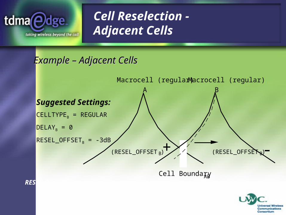
Cell Reselection - Adjacent Cells
Example – Adjacent CellsExample – Adjacent Cells
Suggested Settings:
CELLTYPEB = REGULAR
DELAYB = 0
RESEL_OFFSETB = -3dB
Cell BoundaryAB
Macrocell (regular)
A
Macrocell (regular)
B
(RESEL_OFFSETB)+ (RESEL_OFFSETB)-
RESEL_OFFSET provides hysteresis between two adjacent cells

Cell Reselection - Delay
NL Delay – MicrocellsNL Delay – Microcells
mobile direction
RSS_ACC_MIN
DELAY
C D
Macrocell (overlay)
Microcell
A
B
Suggested Settings:
CELLTYPEB = Preferred
DELAYB = 1 or more hyperframes;
Delay should be set high enough to keep high mobility mobiles off microcell
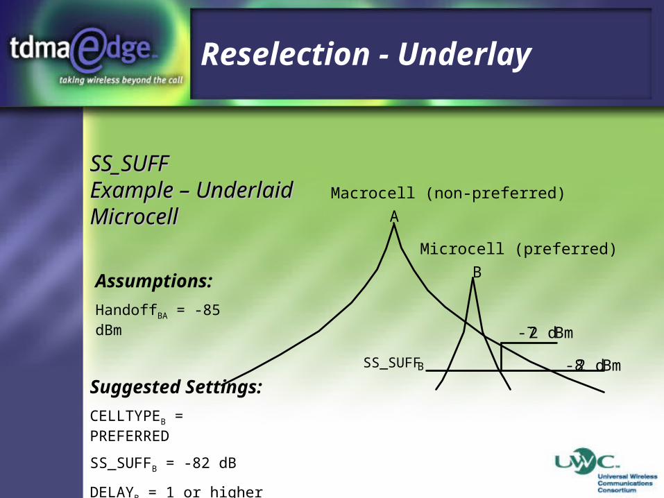
Reselection - Underlay
SS_SUFFSS_SUFFExample – Underlaid Example – Underlaid Microcell Microcell
Assumptions:
HandoffBA = -85 dBm
Suggested Settings:
CELLTYPEB = PREFERRED
SS_SUFFB = -82 dB
DELAYB = 1 or higher
-82 dBm
Macrocell (non-preferred)
Microcell (preferred)
A
B
-72 dBm
SS_SUFFB

Total System Integration
Cell ReselectionCell Reselection
Private/PublicPrivate/PublicSystemsSystems
HierarchicalHierarchicalCellsCells
TDMATDMAC
apacity
Sea
mle
ss
Flexibility
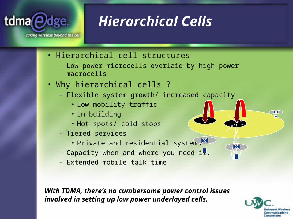
Hierarchical Cells
• Hierarchical cell structures– Low power microcells overlaid by high power macrocells
• Why hierarchical cells ?– Flexible system growth/ increased capacity
• Low mobility traffic• In building• Hot spots/ cold stops
– Tiered services• Private and residential systems
– Capacity when and where you need it.– Extended mobile talk time
With TDMA, there’s no cumbersome power control issues involved in setting up low power underlayed cells.

Capacity: Cell Split Alternative
Cold Spot:Fill-in
A Capacity Tool - Hierarchical Cells
Due to hierarchical deployment, TDMA offers the best long-term RF capacity story
Capacity: Traffic Relief
Cold Spot: EconomicRemoteCoverage
Capacity:In Building Application
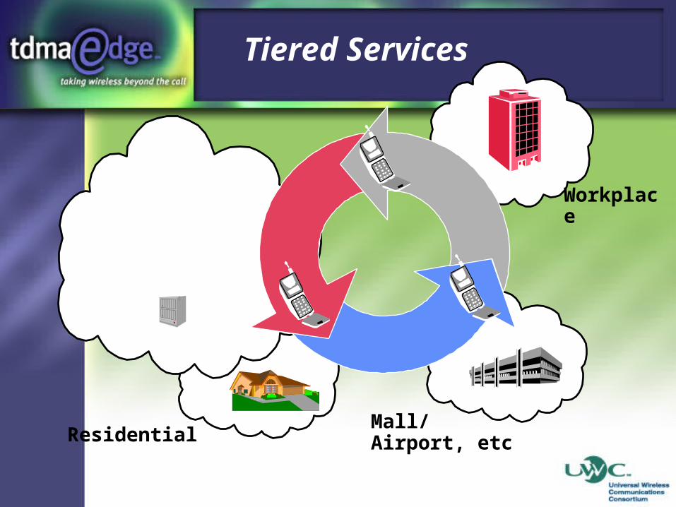
Tiered Services
Public
Residential
Workplace
Mall/ Airport, etc.
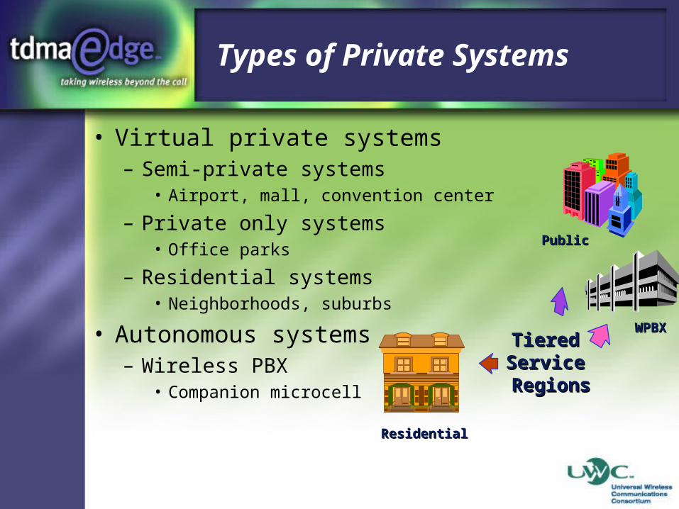
Types of Private Systems
• Virtual private systems– Semi-private systems
• Airport, mall, convention center
– Private only systems• Office parks
– Residential systems• Neighborhoods, suburbs
• Autonomous systems – Wireless PBX
• Companion microcell
ResidentialResidential
Tiered Tiered Service Service RegionsRegions
WPBXWPBX
PublicPublic

Basic Capabilities
• Capabilities provided through TDMA include:– Seamless system transition between private and
public systems
– Differentiated charging
– Alphanumeric display of serving system
– Underlays and in building support
– Private only or semi-private
– Possible to define multiple private systems off a single DCCH
Due to TDMA cell reselection and hierarchical deployment, TDMA offers strongest tiered services story.

The Mechanics of Tiered Services
• Cell Reselection Algorithms: – Seamless DCCH transition between public and private systems.
• Registration Procedures: – Assign and remove subscribers from system– Remove risk of nuisance registrations.
• System Identities: – Private and residential system IDs uniquely identify a system– Network type (3 bit map on the DCCH) defines a cell as public, private, residential, or
semiprivate.
• Alpha Tags: – Identify systems to subscribers by alphanumeric name.
• System Priorities: – Users rank private, residential, or public systems according to preference.

TDMA - Digital PCS
TDMA ScorecardTDMA Scorecard
Dual-Band Standard ¦ PCS at 800 & 1900 MHz
Terminals ¦ Dual-band, cost effective
Voice Quality ¦ EFRC MOS - wireline equivalent
Capacity ¦ N=5/4 reuse and underlays
Enhanced Services ¦ SMS, Over-the-Air Activation, Sleepmode, IS-41C, ...
In-building Services ¦ Hierarchical cell structure for underlays and WPBX
Data ¦ Circuit switched using IS-135High speed data evolution path
Roaming ¦ 1900 / 800MHz TDMA & AMPS Intelligent directed roaming
Fixed & Mixed ¦ Mobility, fixed, & mixed
Services and Design Examples
• Short message service features and examples• Over-the-air activation• Wireless office design example• Circuit switched data service• TDMA summary

Cellular Messaging
• Enables alphanumeric messages to be exchanged between the network and a DCCH capable phone.
• Message delivery is acknowledged.• Message attributes dictate phone behavior.• Includes two way messaging and in-call delivery.
base station
meeting isLarry: the
canceled
Larry: themeeting iscanceled
message
TNPP TAP
Voice
IS-41
. . . . . .. . . . . .. . . . . ...
MSC
center
meeting is
canceled
Larry: the
. . . . . .
Larry: themeeting iscanceled
Messaging Examples
• One-way information services– News, stock quotes, sports scores.
– Broadcast services • Traffic, weather, etc.
• E-mail notifications– Containing “from,” “subject” and first part of message.
• Paging– Both one- and two-way paging with responses and acknowledgments.
• Platform for integrated messaging solutions– Voice mail, etc.
On-Air Activation
• Enables delivery of NAM information and updates to the phone over the air.
• Simplifies the activation process for both the subscriber and service provider.
• Provides a flexible download capability. • Provides a secure mechanism for A-key
updates.
WOS Design Example
• RF planning• Hierarchical cell structure design• System identities• Registration• Phone programming

Why Use a Hierarchical Cell Structure ?
• To bias the weaker cell
• Ease of design
MacrocellBase station
MacrocellBase station
Microcell
Microcell

HCS in an Indoor/Outdoor Site
MacrocellBase Station
Microcell
Microcell
R
P
NP
R
NP
P
P
NP
RR
P
NP
MacrocellBase Station
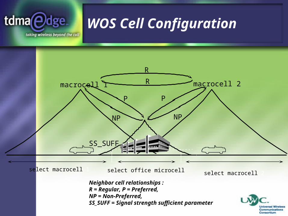
WOS Cell Configuration
macrocell 1
SS_SUFF
select macrocell 1
Neighbor cell relationships :R = Regular, P = Preferred,NP = Non-Preferred,SS_SUFF = Signal strength sufficient parameter
select office microcell select macrocell 2
macrocell 2
R
R
P
NP NP
P
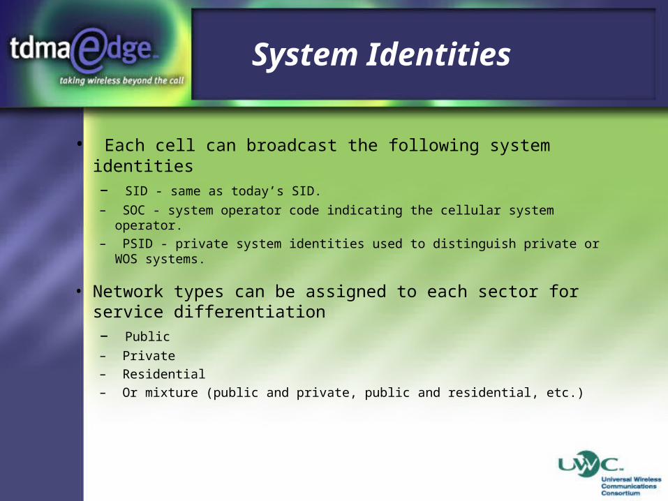
System Identities
• Each cell can broadcast the following system identities– SID - same as today’s SID.
– SOC - system operator code indicating the cellular system operator.– PSID - private system identities used to distinguish private or WOS
systems.
• Network types can be assigned to each sector for service differentiation– Public
– Private– Residential– Or mixture (public and private, public and residential, etc.)
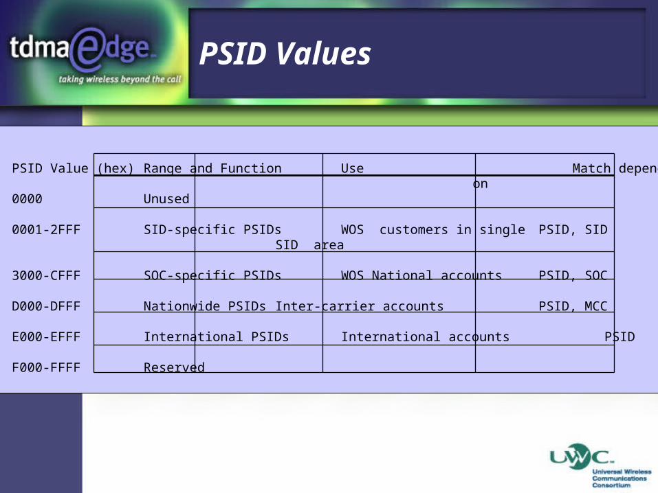
PSID Values
PSID Value (hex) Range and Function Use Match dependent
on0000 Unused
0001-2FFF SID-specific PSIDs WOS customers in single PSID, SIDSID area
3000-CFFF SOC-specific PSIDs WOS National accounts PSID, SOC
D000-DFFF Nationwide PSIDs Inter-carrier accounts PSID, MCC
E000-EFFF International PSIDs International accounts PSID
F000-FFFFReserved

SID and PSID Registration
SID = 47
SID = 33
SID = 33, PSID = 1000
REG
REG
REG
REG
REG
REG
SID Change Registration
PSID Change Registration
(when phone enters cell with different PSID status)
REG
REG
REGREG
SID = 33, PSID = 1000
SID Border

PSIDs and Location ID
Broadcast Parameters
SID = 47SOC = 801PSID1 = 1228PSID2 = 5760PSID3 = 2151PSID5 = 11127
EnterprisesAOB
AssociatesHawthorn
WirelessAT&T
MemorialGillarde
Hospital
HawthornAssociates
GillardeMemorialHospital
AT&TWireless
AOBEnterprisesInc
Inc.
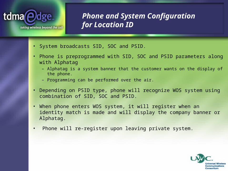
Phone and System Configuration for Location ID
• System broadcasts SID, SOC and PSID.
• Phone is preprogrammed with SID, SOC and PSID parameters along with Alphatag– Alphatag is a system banner that the customer wants on the display of the phone.– Programming can be performed over the air.
• Depending on PSID type, phone will recognize WOS system using combination of SID, SOC and PSID.
• When phone enters WOS system, it will register when an identity match is made and will display the company banner or Alphatag.
• Phone will re-register upon leaving private system.

TDMA Data Services
• TDMA introduces a digital circuit-switched service for session- based transactions like fax and dial-up network access.
• Compare to packet data for short sporadic transactions.

Circuit-Switched and Packet Data
• Circuit-Switched Data – Transactions rely on a call being established.– Channel and resources are occupied by a single user.
– Efficient for fax, file transfers and where data is being exchanged for a high
proportion of the connect time.
• Packet Data– “Connectionless” service (no call setup overhead).– Many users share the same radio channel.– Efficient for short, bursty, sporadic transactions (like e-mail, web browsing
or virtual connections).
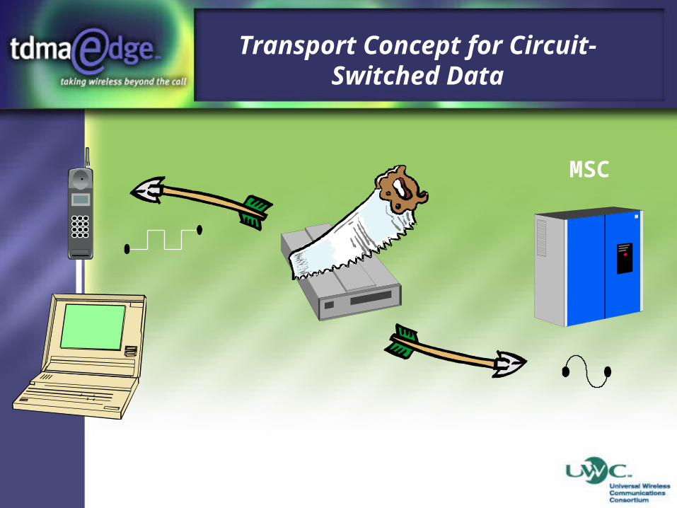
Transport Concept for Circuit- Switched Data
MSC
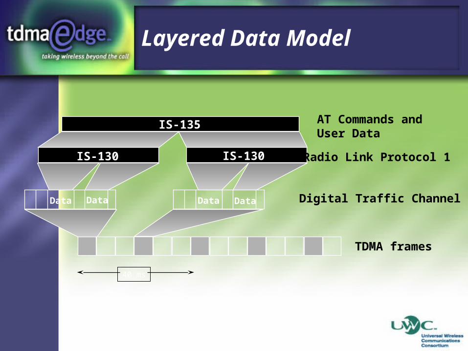
Layered Data Model
40 ms
IS-135
IS-130 IS-130
Digital Traffic Channel
TDMA frames
AT Commands andUser Data
Radio Link Protocol 1
Data Data DataData

Data Standards
• IS-130 - Radio Link Protocol– Error control – Compression– Encryption
• IS-135 - Async Data and Fax– Data call setup, supervision, and clearing– AT-command handling– Signal leads
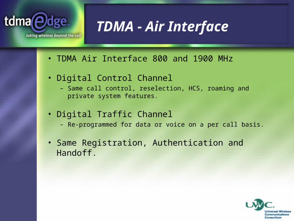
TDMA - Air Interface
• TDMA Air Interface 800 and 1900 MHz
• Digital Control Channel– Same call control, reselection, HCS, roaming and private
system features.
• Digital Traffic Channel– Re-programmed for data or voice on a per call basis.
• Same Registration, Authentication and Handoff.
26
Radio Resources
• Uses same Digital Traffic Channel resources– Trunking efficiency– Configurable per call– Controlled by switch– Optimization and O&M the same as traffic
channels.
TDMA Features
• Perfect faxes delivered real-time at about two pages per minute.
• File transfers could be up to 115,200 bit/s with triple rate channel and compression (depending on data)
– Full Rate - 9.6 kbit/s uncompressed - 38.4 kbit/s compressed
• Detects and correct errors, compresses and encrypts data.• No special modem or fax machine required on wireline side.• Phone looks like a wireline fax/data modem.• Compatible with existing software.
– Future Windows unimodem will also contain built in support.
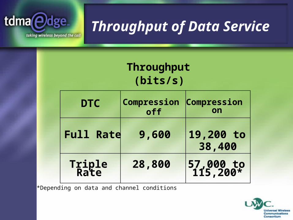
Throughput of Data Service
Throughput(bits/s)
*Depending on data and channel conditions
DTC Compressionoff
Compressionon
Full Rate 9,600 19,200 to38,400
TripleRate
28,800 57,000 to115,200*

Future Data Activities
• Multi-slot Operation– Concatenate timeslots to give higher throughput.
• Direct IP Connectivity.
• Browser Activity Increasing in TDMA Arena.
• Packet Data Transport in TDMA Environment– Standard in development– Provides integrated packet data solution for TDMA.

Future TDMA Features
• Broadcast Short Message Service
• Enhanced Talk Time– Discontinuous mode (DTX) with comfort noise doubles talk time
• Integrated TDMA Packet Data Solution
• Teleservice Transport Enhancements– Segmentation– Assignment to traffic channel for long messages

TDMA Benefits
• The DCCH is a method for rapid deployment of advanced services based on existing AMPs infrastructure.
• The DCCH is the platform for seamless 800 MHz and 1900 MHz PCS implementation.
• The DCCH offers new features to our customers.
TDMA Benefits - cont.
• Cost– TDMA can coexist with existing AMPS radios and frequencies.– Digital capability can be introduced when and where it’s needed.
– AMPs equipment can be selectively upgraded or redeployed.
• Capacity – TDMA introduces at least a threefold increase over AMPS capacity
• Even greater with use of Hierarchical Cell Structures, Adaptive Channel Allocation etc.
• Voice Quality – ACELP vocoder significantly improves voice quality.
• Roaming– Dual mode handsets and AMPS/TDMA compatibility ensures ubiquitous network
access.

TDMA Summary
• Enhanced Services Sleep mode Voice privacy Authentication Message waiting indicator Calling number identification Circuit switched data Short message service Private system features Hierarchical Cell Structures 800 and 1900 MHz Operation On air activation.


