TE APITI WIND FARM TURBINE FOUNDATIONS: DESIGN AND CONSTRUCTION Robert Davey 1 and Rob Green 2 INTRODUCTION Meridian Energy’s Te Apiti wind farm is located on hilly country immediately north of the Manawatu Gorge in the southern-most region of the Ruahine range, being situated between the small rural towns of Ashhurst to the west and Woodville to the east. Access is via Saddle Road which passes through the farm. Electrical power is generated by 55 wind turbines each of 1.65MW capacity, with 70m hub heights, and is fed into the national electrical grid at a Trans Power substation at Woodville. The turbines are supported on tubular steel towers with a 4.2m base diameter and 30mm wall thickness. The turbines along with their rotors, towers and electrical equipment were supplied by NEG MICON (now part of the Danish Vestas company). As can be seen in Figure 1, these large structures are now a striking feature of the local landscape. What are not so obvious are the foundations that support them. In this paper we present the methods that were used for the design and construction of these foundations. 1 Manager Civil Engineering, Opus International Consultants Ltd, Wellington 2 Manager Concrete Division, Higgins Group, Palmerston North GEOTECHNICAL INVESTIGATION A comprehensive geotechnical investigation of the wind farm site was undertaken by Opus geologists and geotechnical engineers [1], comprising: • Site inspections and geological mapping of turbine sites, the electrical substation site, access track routes and transmission line routes; • Site investigations at a sample of sites, including 7 boreholes and 43 trial pits; • Plate bearing site testing of ground stiffness; • Laboratory testing of soil/rock samples to determine the strength of site materials. The main geological units within the wind farm are blue grey mudstones with unconfined compressive strengths in the range 0.25 to 1MPa; and gravel and sand conglomerates with unconfined compressive strengths in the range 1 to 5MPa. The active Wellington and Ruahine fault lines are located 3km and 0.5km respectively from the boundaries of the site. As a result of this investigation an ultimate foundation bearing capacity of 700kPa was adopted. The soil shear modulus was assessed to be in excess of 40MPa. WIND TURBINE FOUNDATION OPTIONS Three options were considered for the foundations: Shallow Gravity Foundations (Figure 2) These concrete pad foundations are suitable for most ground conditions, the exception being non- rippable rock. The pads are usually square or octagonal in plan. This type of foundation was selected for Te Apiti. Rock Anchored Foundations (Figure 3) These may be economically feasible for competent non-fractured rock. In comparison to the gravity foundation a much smaller footprint is required giving savings on excavation and concrete quantities. The Te Apiti geology does not suit this foundation type. Monopile Foundations The monopile foundation consists of an open ended steel pile with the same diameter as the tower, acting as a laterally loaded pile. The pile is installed by forming a slot-drilled annulus for insertion of the pile followed by grouting. This requires specialist drilling equipment that is not presently available in New Zealand. At Te Apiti, the tower shaft is anchored to the foundation pad with an embedded section of the shaft (the “embedment cylinder”), as shown in Figure 2. The other system that is commonly used is anchor bolts cast into the pad.
Transcript
TE APITI WIND FARM TURBINE FOUNDATIONS: DESIGN AND CONSTRUCTION
Robert Davey1 and Rob Green
2
INTRODUCTION
Meridian Energy’s Te Apiti wind farm is located on hilly country immediately north of the Manawatu Gorge in the southern-most region of the Ruahine range, being situated between the small rural towns of Ashhurst to the west and Woodville to the east. Access is via Saddle Road which passes through the farm. Electrical power is generated by 55 wind turbines each of 1.65MW capacity, with 70m hub heights, and is fed into the national electrical grid at a Trans Power substation at Woodville. The turbines are supported on tubular steel towers with a 4.2m base diameter and 30mm wall thickness. The turbines along with their rotors, towers and electrical equipment were supplied by NEG MICON (now part of the Danish Vestas company). As can be seen in Figure 1, these large structures are now a striking feature of the local landscape. What are not so obvious are the foundations that support them. In this paper we present the methods that were used for the design and construction of these foundations.
1 Manager Civil Engineering, Opus International Consultants Ltd, Wellington
2 Manager Concrete Division, Higgins Group, Palmerston North
GEOTECHNICAL INVESTIGATION A comprehensive geotechnical investigation of the wind farm site was undertaken by Opus geologists and geotechnical engineers [1], comprising:
• Site inspections and geological mapping of turbine sites, the electrical substation site, access track routes and transmission line routes;
• Site investigations at a sample of sites, including 7 boreholes and 43 trial pits;
• Plate bearing site testing of ground stiffness;
• Laboratory testing of soil/rock samples to determine the strength of site materials.
The main geological units within the wind farm are blue grey mudstones with unconfined compressive strengths in the range 0.25 to 1MPa; and gravel and sand conglomerates with unconfined compressive strengths in the range 1 to 5MPa. The active Wellington and Ruahine fault lines are located 3km and 0.5km respectively from the boundaries of the site. As a result of this investigation an ultimate foundation bearing capacity of 700kPa was adopted. The soil shear modulus was assessed to be in excess of 40MPa.
WIND TURBINE FOUNDATION OPTIONS Three options were considered for the foundations: Shallow Gravity Foundations (Figure 2) These concrete pad foundations are suitable for most ground conditions, the exception being non-rippable rock. The pads are usually square or octagonal in plan. This type of foundation was selected for Te Apiti. Rock Anchored Foundations (Figure 3) These may be economically feasible for competent non-fractured rock. In comparison to the gravity foundation a much smaller footprint is required giving savings on excavation and concrete quantities. The Te Apiti geology does not suit this foundation type. Monopile Foundations The monopile foundation consists of an open ended steel pile with the same diameter as the tower, acting as a laterally loaded pile. The pile is installed by forming a slot-drilled annulus for insertion of the pile followed by grouting. This requires specialist drilling equipment that is not presently available in New Zealand. At Te Apiti, the tower shaft is anchored to the foundation pad with an embedded section of the shaft (the “embedment cylinder”), as shown in Figure 2. The other system that is commonly used is anchor bolts cast into the pad.
DESIGN LOADS
Design Standards The guiding standard used for the design of wind turbine foundations is the International Electrotechnical Commission document IEC 61400-1: Wind Turbine Generator Systems- Part 1 Safety Requirements [2]. This standard specifies the structural performance requirements of the support structure including the foundations. Foundations for wind turbines are low-frequency machine-loaded structures subjected to coupled horizontal-rocking vibrations. The turbine-specific load spectra were calculated by NEG MICON using an aero-elastic computer model of the turbine. The load spectrum for the Te Apiti turbines was based on a 20 year turbine life. Seismic loads were calculated by Opus in accordance with the New Zealand loading standard, NZS4203 [3]. Seismic loads, based on fully elastic response, are less than the extreme wind loads. The following loads are relevant to the design of the foundations: Extreme Loads The foundations were designed to withstand the extreme loads considering the following potential failure mechanisms:
• Bearing failure of the soil;
• Overturning of the tower and foundation;
• Flexural and shear failure of the reinforced concrete pad;
• Loss of anchorage of the tower embedment cylinder within the pad.
The IEC standard extreme design wind speeds were compared to the wind loading code AS/NZS 1170.2 [4] ULS design wind speeds for the site and were found to be in excess of the 500 year wind speeds. Production Loads The production loads were used to check the serviceability of the structure, including consideration of the foundation stiffness in order to avoid resonance under the cyclic loading from the rotating turbine and consequential load amplification. Fatigue Loads Fatigue analyses were carried out to ensure that the foundation structure fulfils its intended function under the large numbers (10
9) cycles of load it will
be subjected to throughout its design lifetime.
STRUCTURAL ANALYSIS AND DESIGN
Pad Sizing Preliminary design studies were undertaken with a simple rigid disk model of the pad to optimise the diameter and thickness of the pad, and the depth of overburden which also contributes to the stability of the structure. In most cases the water table was located well below the underside of the foundation pad, so that buoyancy forces could be neglected in the design. However in a few cases it was necessary to install drains to ensure that this condition was maintained at all times. The pads are 16m wide octagonal shape with depths varying from 2.55m at the centre to 1.5m at the edges. Each pad contained 375m
3 of 30MPa
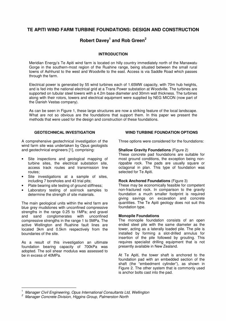
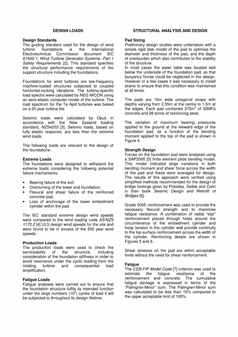
concrete and 28 tonne of reinforcing steel. The variation of maximum bearing pressures applied to the ground at the leeward edge of the foundation pad, as a function of the bending moment applied to the top of the pad is shown in Figure 4. Strength Design Forces on the foundation pad were analysed using a SAP2000 [5] finite element plate bending model. This model indicated large variations in both bending moment and shear force across the width of the pad and these were averaged for design. The results of this approach were verified using simplified methods recommended for the design of bridge footings given by Priestley, Seible and Calvi in their book Seismic Design and Retrofit of Bridges [6]. Grade 500E reinforcement was used to provide the necessary flexural strength and to maximise fatigue resistance. A combination of radial “star” reinforcement placed through holes around the circumference of the embedment cylinder and hoop tension in the cylinder wall provide continuity to the top surface reinforcement across the width of the cylinder. Reinforcing details are shown in Figures 5 and 6. Shear stresses on the pad are within acceptable limits without the need for shear reinforcement. Fatigue The CEB-FIP Model Code [7] criterion was used to estimate the fatigue resistance of the reinforcement and concrete. The cumulative fatigue damage is expressed in terms of the “Palmgren-Minor” sum. The Palmgren-Minor sum was calculated to be less than 10% compared to the upper acceptable limit of 100%.
Transfer of Tower Forces to Pad One of the more challenging aspects of the foundation design was to resolve the transfer of the vertical forces (both tension and compression) from the tower steel shell into the pad concrete via the embedment cylinder. There are no generally accepted, codified design rules for this type of structure, that the authors are aware of. Hand analyses of the embedment cylinder/pad joint region indicated that the forces are transferred by a combination of “dowel” action (the tube leveraging within the concrete pad) and a diagonal strut mechanism with the forces transferred by shear friction between the tower shell and the concrete in the concrete compression stress zones. This analysis was later confirmed by 2-D and 3-D finite element modelling of the joint. The embedment cylinder is normally supplied with a corrosion resistant coating that would substantially reduce the friction coefficient, so the Te Apiti cylinders were specified to be uncoated below the level of the concrete surface as shown in Figure 5 for example. Foundation Stiffness NEG MICON specified the minimum rocking stiffness of the pad foundation required to comply with the parameters used in their load modelling. The stiffness of the foundation was calculated using the expression given in Moore [8] for a rigid circular disk on an elastic half-space as follows:
( )ν−=
13
83
GrK
Where:
K = rocking stiffness
G = shear modulus
r = disk radius
ν = Poisson’s ratio.
Including an allowance for actual pad stiffness, the minimum allowable shear modulus of the soil was calculated to be 15MPa, which is less than the minimum shear modulus at the turbine sites of 40MPa.
CONSTRUCTION
Concrete Mix The foundations are thick (2.55m maximum) and contain a large volume of concrete. There was therefore a risk that large temperature rises associated with heat-of-hydration effects could result in thermal gradients across the depth of the pad sufficient to cause thermal cracking. The concrete supplier, Higgins Concrete Ltd, therefore designed a concrete mix to control the temperature rises.
This was achieved primarily by the partial substitution of the highly reactive Type GP cement by fly-ash, which is a pozzolanic material. Fly-ash possesses little or no hydraulic cementitious properties in its own right. Rather, it reacts with the calcium hydroxide (lime) released as a by-product of the hydration of Portland cement to produce further quantities of calcium silicate gel. The secondary nature of the pozzolanic reaction with its relatively slow rate as compared to the hydration characteristics of Portland cement serves to stagger the evolution of heat over a much longer time frame. This so reduces the expected magnitude of peak temperature levels as the extended time span enables greater amounts of heat loss from the body of concrete in the interim. In addition to reducing heat gain, the thermal gradient was controlled by covering the upper surface of the pad with a 50mm thick insulating sand layer immediately after pouring to prevent rapid loss of heat from the top surface. To check the effectiveness of these measures, three thermocouple devices were installed near to the centre of the first two tower bases poured. One device was placed within 100mm of the top surface, one at mid-depth and the other within 100mm of the bottom surface. Results from one of the tests are shown in Figure 7. The maximum temperature differential recorded was 18
oC, which
is less than the 25oC maximum that is generally
taken as the limit above which there is a high risk of thermal cracking, confirming that the control measures were successful. Concrete Production and Placing The concrete was supplied from an on-site
batching plant (Figure 8). The batch plant type was
a Con-E-Co LoPro 10 bought from the USA
specifically for the project. Rated to produce in
excess of 100m³ / hr, in reality it was able to
produce at 70m³ to 80m³ /hr for extended periods.
Between five and nine 5m³ mixer trucks were used,
depending on the proximity to the plant for each
pour.
All materials, aggregates, cement, fly ash had to be
carted into the batching plant site including 42,000
litres of water for each pour.
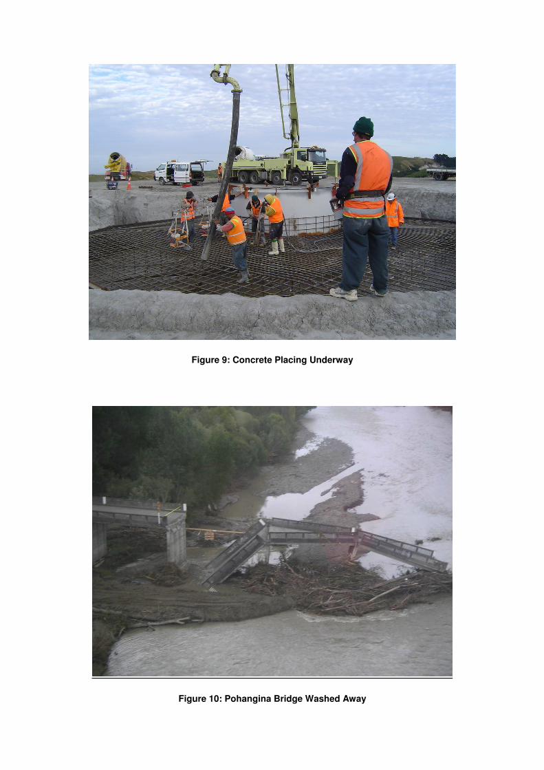
In almost all cases, access to the site at each tower base was restricted to only one side and the 16m diameter of the bases necessitated the use of a boom pump for the concrete placement (Figure 9). A minimum pumping rate of 50m³ / hr was required to maintain concrete placement continuity.
Despite the use of 30mm crushed aggregate and reduced cement content, the fly-ash in the concrete
was able to enhance the pumping characteristics sufficiently to avoid having to make any special measures. The minimum pumping rate of 50m³ / hr was consistently achieved with no pumping problems requiring alterations to the mix. The concrete was placed in 300 – 500mm layers working in a rotational direction around the centre of the tower base. With a placing rate of 50 – 60m³ / hr the fresh concrete would be covering already placed concrete about an hour later. It was found that the fly-ash in the mix delayed the setting time sufficiently to allow for adequate compaction between the two layers. The choice of fly-ash as a partial cement replacement proved to be an excellent decision as it played a major role in enabling Higgins to overcome some of the challenges they faced in satisfying the technical requirements of the project. Construction Challenges On 16 February the Manawatu region experienced a 100-year flood event which isolated the Te Apiti site completely from Palmerston North, the source of all material and labour. The Pohangina Bridge at the Ashhurst end of Saddle Road was washed away (Figure 10), and the alternate access through the Manawatu Gorge also experienced severe slips and was closed for 8 weeks. Higgins arranged alternative supplies of cement from Napier, and fly-ash and labour were transported via the Paihiatua Track, a four hour round trip. These alternatives were not practical for aggregates, so they were stockpiled on the Ashhurst side of the Pohangina River and taken across the river in dumpers to a stockpile on the Saddle Road side for subsequent transport to the batch plant.
CONCLUSION Construction of Te Apiti first began on 10 November 2003 with the excavation and construction of 21kms of road and the turbine platforms and foundations. Despite very adverse weather conditions experienced, with 166 days out of 366 lost to bad weather, and the bridge washout, work remained on track for the first turbine to generate electricity on 26 July 2004. By 25 October 2004 and ahead of programme, all 55 turbines were fully commissioned.
ACKNOWLEDGEMENTS
The permission of Meridian Energy Ltd to publish this paper is gratefully acknowledged.
The authors also wish to make special mention of Te Apiti Project Manager David Green and other members of the Meridian team, the Opus design team, Dr John Wood who peer reviewed the design and the Higgins construction team; all of whom made major contributions to the design and construction of the turbine foundations.
REFERENCES
[1] Murashev A 2005. Te Apiti Wind farm:
Megawatt – class Machines Aided by
Geotechnical Expertise. New Zealand
Geomechanics New, Issue 69, June 2005.
[2] IEC61400-1, Wind Turbine Generator
Systems – Part 1 Safety Requirements,
International Electrotechnical Commission,
1999.
[3] NZS4203:1992, Loadings Standard,
Standards New Zealand.
[4] AS/NZS1170.2:2002, Structural design
actions, Part 2: Wind actions, Standards
New Zealand.
[5] SAP2000: Three dimensional static and
dynamic finite element analysis and design
of structures, Computers and Structures Inc,
2000.
[6] Priestley MJN, Seible F and Calvi GM,
Seismic Design and Retrofit of Bridges, John
Wiley and Sons.
[7] CEP-FIP Model Code, Thomas Telford
1990.
[8] Moore PJ, Analysis and Design of
Foundations for Vibrations, AA Balkema,
1985.
Figure 1: Te Apiti Wind Farm Turbines
Figure 2: Shallow Gravity Foundation
Figure 3: Anchored Foundation
Figure 4: Bending Moment at Top of Pad vs. Maximum Bearing Pressure
Figure 5: Bottom Reinforcement, Embedment Cylinder and “Star” Reinforcement in Place
Figure 6: Top Reinforcement in Place and Ready for Pouring Concrete