S' I il T.e C4&At )TC No. 13444 A SURVIVABLE TACTICAL TRUCK RADIATOR A CONCEPTUAL AND FEASIBILITY STUDY DAAE07-88-C-R066 JUNE 1989 T.S. Ravigururajan and M.R. Beltran Beltran, Inc. 1133 E. 35th Street By Brooklyn, NY 11210 APPROVED FOR PUBLIC RELEASE: DISTRIBUTION IS UNLIMITED S003 /,)./(O 141. U.S. ARMY TANK-AUTOMOTIVE COMMAND RESEARCH, DEVELOPMENT & ENGINEERING CENTER Warren, Michigan 48397-5000
Transcript
S' I il
T.e C4&At )TCNo. 13444
A SURVIVABLE TACTICAL TRUCK RADIATOR
A CONCEPTUAL AND FEASIBILITY STUDY
DAAE07-88-C-R066
JUNE 1989
T.S. Ravigururajan and M.R. BeltranBeltran, Inc.1133 E. 35th Street
By Brooklyn, NY 11210
APPROVED FOR PUBLIC RELEASE:DISTRIBUTION IS UNLIMITED
S003 /,)./(O 141.
U.S. ARMY TANK-AUTOMOTIVE COMMANDRESEARCH, DEVELOPMENT & ENGINEERING CENTERWarren, Michigan 48397-5000
NOTICES
This report is not to be construed as an official Department of the Armyposition.
Mention of any trade names or manufacturers in this report shall not beconstrued as an official endoresement or approval of such products orcompanies by the U.S. Government.
Destroy this report when it is no longer-needed. Do not return it to theoriginator..
UnclassifiedSECURITY CLASSIFICATION OF THIS PAGE
I Form ApprovedREPORT DOCUMENTATION PAGE oMB No. 0704-0188
2a. SECURITY CLASSIFICATION AUTHORITY 3. DISTRIBUTION /AVAILABILITY OF REPORT
Approved for public release:2b. DECLASSIFICATION/ DOWNGRADING SCHEDULE Distribution is unlimited
4. PERFORMING ORGANIZATION REPORT NUMBER(S) S. MONITORING ORGANIZATION REPORT NUMBER(S)
13444
6a. NAME OF PERFORMING ORGANIZATION 6b. OFFICE SYMBOL 7a. NAME OF MONITORING ORGANIZATIONI (If applicable)Beltran, Inc. I_(ifappliable) U.S. Army Tank - Automotive Command
6c. ADDRESS (City, State, and ZIP Code) 7b. ADDRESS (City, State, and ZIP Code)
1133 E. 35th Street Warren, MI 48397-5000Brooklyn, NY 11210
8a. NAME OF FUNDING/SPONSORING 8b. OFFICE SYMBOL 9. PROCUREMENT INSTRUMENT IDENTIFICATION NUMBERORGANIZATION (if applicable) DAAE07-88-C-R066
8c. ADDRESS (City, State, and ZIP Code) 10. SOURCE OF FUNDING NUMBERSPROGRAM PROJECT I TASK WORK UNITELEMENT NO. NO. NO. IACCESSION NO.
11. TITLE (Include Security Classification) I......A Survivable Tactical Truck Radiator - A Conceptual and Feasibility Study (u)
12. PERSONAL AUTHOR(S)Ravigururajan, T.S. and Beltran, M.R.
13a. TYPE OF REPORT 113b. TIME COVERED 14. DATE OF REPORT SVear, Month, Day) 115. PAGE COUNTFinal FROM 88 9 TO 89 5/9 9 June30 84
16. SUPPLEMENTARY NOTATION
17. COSATI CODES 18. SUBJECT TERMS (Continue on reverse if necessary and identify by block number)FIELD GROUP SUB-GROUP. Survivable tactical truck radiator
_ Heat pipes
19. ABSTRACT (Continue on reverse if necessary and identify by block number)The single most important design factor faced by the cooling systpms in tactical truck- istheir vulnerability to exploding shells, sniper fire, and other projectiles. This projectproposes to use heat pipes in radiators to transfer waste heat from the engine to thesurrounding environment. In the phase I concept feasibility study, a computer programwas developed to design a small scale heat pipe radiator module. Experimental tests wereperformed on this maodule to test the validity of the design methodology and tA study thevulnerability characteristics of the heat pipe radiator for a wide range of operatingparameters such as air velocity, coolant flow rates, and the number of heat pipes damaged.The results showed that a heat pipe radiator will provide the necessary limp home capabilityfor tactical trucks even with 50 % of the heat pipes damaged. Also, when the radiatorsare operating at leas than peak capacity (slower vehicle speeds), the undamaged heat pipessubstantially compensated for the damaged heat pipes adding to the reliab'ility of the system.The development mnd testing of a prototype will be taken un in the Phase II of the program20. DISTRIBUTION /AVAILABILITY OF ABSTRACT 21. ABSTRACT SECURITY CLASSIFICATION
OUNCLASSIFIED/UNLIMITED 0 SAME AS RPT. ,0 DTIC USERS Unclassified22a. NAME OF RESPONSIBLE INDIVIDUAL 22b. TELEPHONE (include Area Code) 22c. OFFICE SYMBOL
M. L. Goryca (313) 574-85321 AMSTA-RGTDD Form 1473, JUN 86 Previous editions are obsolete. SECURITY CLASSIFICATION OF THIS PAGE
5-30. Geometric Arrangement of Wick Channels ...................... 55
LIST OF TABLES
Table Title Page
5-1. Water Flowrate (gpm) ........................................ 96
4
1.0. INTRODUCTION
This final technical report, prepared by Beltran, Inc., forthe U.S. Army Tank-Automotive Command (TACOM) under ContractDAAEO7-88-C-R066, describes Phase I work in the developmentof a survivable tactical truck heat pipe radiator.Combat/tactical military vehicles face difficult operatingand terrain conditions. These vehicles are normally
* provided with armor; yet, their protection depends on theiroperating condition and other tactical criteria. For thispurpose, the engine and its supporting systems are envelopedin an armored compartment within the vehicle, with airflowthrough metallic grilles. The space for the cooling systemin the engine compartment is quite restricted.
The single most important design factor faced by the coolingsystem is its vulnerability to exploding shells, sniper fireand other projectiles. At present, these threats areminimized by providing ballistic grills, or placing thesystem in an armored envelope.
This project proposes to use heat pipes in radiators totransfer heat from coolant to air (or from other liquidslike transmissions and hydraulic oils). If one or more heatpipes are damaged, the remaining pipes can pick up the load.This will increase the reliability of the radiator. Thisfeasibility/conceptual study shows the effectiveness of aheat pipe radiator.
2.0. OBJECTIVE
It is the objective of the Phase I project, by using a modelheat pipe network module, to:
* develop a computer model
0 design, fabricate, test and evaluate radiator
0 deliver a radiator test section to TACOM
3.0. CONCLUSIONS
The analytical and experimental work has shown that theseobjectives are practical and can be implemented successfullyin a prototype radiator. The salient features of the studywere as follows:
The analytical and experimental study proved thecorrectness of the design methodology and approach to
5
be adopted in the Phase II work on the prototype heatpipe radiator.
The effect of air flow rates is to increase theperformance drastically before levelling off at veryhigh velocities.
At high engine RPM, the heat pipe radiator performed at85% capacity even with 25% damage to the cone.
At lower engine RPM, the radiator performance wasnearly constant, even with 30% damage.
The pressure drop for this module exhibited theanticipated trend. It increases with air velocityrising more steeply at higher values.
Even at slopes of 60 degrees, the heat exchanger wasable to perform at greater than 80% capacity.
The heat pipe radiator module is more efficient by 25%than similar conventional radiator.
A considerable size and weight reduction, by up to 25%,may be anticipated in a heat pipe radiator.
4.0. RECOMMENDATIONS
Having proved the concept, the next logical step is todevelop a prototype radiator for a typical engine for theM939A2 vehicle. This should be done in several stages.
The radiator should be designed for thermalperformance according to specification AMCP 706-361,taking into account the operating and ambientconditions and other severity conditions, andseveral factors such as:
- long term - storage- mechanical design (shock, vibration, etc.)- terrain conditions
A comprehensive computer program should be developedthat will design the best elemental heat pipe andthe overall radiator design. The thermal design maytake into account the freezing of heat pipes, theoverload factor, design of coolant pump and fan.
With the thermal design in place, the configurationdesign should be done to adapt to existing
6
S-.' -. --,---- . .
radiators. This will include the overalldimensional constraints, mounting techniques andmaintenance criteria.
The fabrication and the experimentation of theradiator should be carried out in a laboratoryenvironment, followed by an actual demonstration ona truck.
A cost study for the heat pipe radiator productionand a comparative analysis with the existingconventional radiator would be necessary as part ofthe prototype of a survivable heat pipe radiator.
5.0. DISCUSSION
5.1. Background
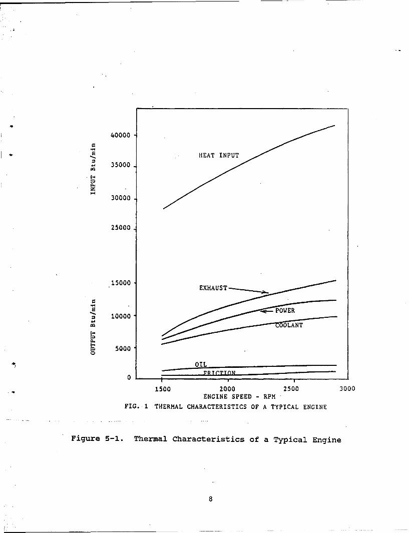
Cooling systems in I.C. engines play a very important rolein rejecting waste heat (Figure 5-1). However, thetatical/conmbat vehicles used by the Armed Forces aIehandicapped by the vulnerability of the radiators . It isthe goal of the study to use heat .pipes for the radiatorsthat will eliminate or greatly reduce the radiatorvulnerability.
The heat pipe is being increasingly studied for a widevariety of applications involving different heat transferprocesses. These applications vary from thm Q8 oling ofelectronic chips to space power generation .
The heat pipe's wide potential may be attributed to itsunique characteristics.
Good thermal response time. Vapor in the heat pipetravels at nearly the speed of sound. For example, ifa heat pipe is dipped in 80 0 C water, the other end ofthe heat pipe will reach 80 0 C almost immediately. Thischaracteristic is especially important for the proposeddesign.
Extremely high thermal conductivity. The heat pipe hasan effective thermal conductivity which is 200 timesthat of copper. This means that for the same size andheat transfer rate, the temperature difference requiredto maintain that rate would be 200 times greater forthe copper bar than the heat pipe. In terms of theproposed design, this means that a 200 times greaterheat transfer rate can be obtained with a heat pipe
7
40000
HETINU
S 35000
30000
25000
.15000EXHUST
S 10000
5000
OIL
0 FRTrTTflN
1500 2000 2500 3000ENGINE SPEED -RPM
FIG. 1 THERMAL CHARACTERISTICS OF A TYPICAL ENGINE
Figure 5-1. Thermal Characteristics of a Typical Engine
8
than with the same size copper rod for the sametemperature difference between the ends.
Temperature uniformity. Uniform temperatures of eachpart in the heat pipe can be obtained throughout itslength. What this means for our design is that atemperature gradient is produced along the length ofthe heat pipe, but that at each section, thetemperature is constant at all points around the heatpipe.
Flexibility in design. The heat pipe allows heattransfer between the two ends, and the actualconfiguration used does not restrict the ability toaccomplish the transfer. Thus the materials used toconstruct the casing may be flexible and easily conformto the particular component or part of vessel. Theworking fluid inside the heat pipe becomes the onething that must be selected for the operating range oftemperatures involved.
Heat pipes are maintenance-free; they function withoutbeing driven electrically or mechanically. Thermal andchemical stability on the inside is adequate. Perfectoperating conditions are maintained over long periodsof time without maintenance. This is an especiallydesirable feature for ensuring continued use of thedevice by personnel.
Heat pipes are lightweight and compact. While thisadvantage is not important in many engineeringapplications, it is especially important wheninterfacing a heat pipe to an existing equipment. Evenif heat pipes had all the superior characteristicslisted above, if this one were lacking, the systemdesign using heat pipes would not be feasible.
Heat pipes are more cost effective than most other heattransfer devices. They are reasonably simple tomanufacture, which results in cost savings duringinitial implementation. Heat pipes are reliable,require virtually no preventive or correctivemaintenance during their operating lifetime.
An important design consideration in the thermal design of aheat exchanger is the determination of its heat transferrate and the ýaV5 rejected from an engine can be estimatedapproximately . In a heat pipe heat exchanger, thepipes may be horizontal, or vertical with the evaporatorsections below the condensers. The angle of the heat pipesmay be adjusted "in situ" as a means of controlling the heat
9
transport. This is a useful feature that can be employed inradiator applications.
Although the heat pipe exchanger has only been in massproduction for approximately a decade, their development anduse indicates a very wide range of applications in industryand commercial and municipal buildings. Their use inliquid-air heat exchangers, and in particular, radiators,
IW will increase the heat transfer ability noticeably. Inconventional radiators, the mechanism of heat transfer issingle phase convection. Replacing plain tubes with heatpipe will introduce boiling and condensation. The increasein heat transfer coefficient due to two-phase flow ismanifold, resulting in a highly efficient and smallerradiator.
5.2. Analysis and Evaluation
Heat pipes, due to their efficiency and simplicity ofoperation, are finding increasing use in industrialapplications, including space and electronic equipment. Yetthe design of a heat pipe is more complex than other heattransfer equipment. This is because of the many processesthat take place simultaneously in a heat pipe. Theseinclude liquid and gas phase flows, condensation andevaporation (with suction or blowing), mass transfer,interfacial energy transfer, heat gain or loss throughconduction, convection and radiation, among other processes.In most applications and designs of heat pipes, all theprocesses and variables are interdependent, which adds tothe intricacy of the problem. In spite of the numerousvariables involved, detailed knowledge on each of theseprocesses has simplified the design of heat pipes.
5.2.1. Governing Equation.
The main regions of a heat pipe are shown in Figure. 5-2.The heat is absorbed in the evaporator section wherein theworking liquid boils at the wick surface. The vapor thenmoves to the condenser section and condenses rejecting heat.This heat can be removed from the heat pipe through anappropriate technique. The condensate is returned to theevaporator section through the capillary pumping due to the
-wick pore and the surface energy of the liquid. The centralsection is the adiabatic section where a pump may beinstalled to import additional pumping power.
10
tA
w Z
0 x
Figure - A Schematic Diagram of a Typical Heat Pipe
- M
The driving force for the working fluid in the heat pipe isprovided by the capillary force while pressure loss isincurred due to viscous drop in liquid and vapor, inertialloss due to the vapor flow. Gravitational force can act foror against the liquid, depending on the flow direction.
The governing equation can then be expressed as
APi + APv + APg p (1)
where
DP1 = liquid viscous drop
APv = viscous and inertial vapor pressure loss
APg - gravitational pressure drop
Apc = capillary force
In physical terms, the capillary limit determines the flowrate, and hence, the capacity of the heat pipe, by balancingthe various pressure loss components.
Substituting the expressions for the pressure drop losses inliquid and vapor, both viscous and inertial, and the drivingforce of capillary action (also known as wicking action),the governing equation for the heat pipe can be expressedas:
The heat load for the heat pipe can be found from thequadratic equation
Q2 + PQ + 7 = 0 (2)
where
S= (l/IAA,) 2 j/PV (a)
JA= 1/AAAwXK[(le +ic)/ 2 + la])
+ 8pr/XpwrVr4 [( 1 e +lc)/ 2 + ia] (b)
12
and
-y 2uc - p1gl] (c)
While the capillary pumping determines the priming capacityand functionality of a wicked heat pipe, several otherconstraints can reduce or hinder efficient operation of aheat pipe and in certain instances can lead to totalbreakdown. Because of this possibility, in heat pipe designand analysis these associated constraints are always takeninto consideration. The various constraints are discussedbriefly in the following section.
5.2.2. Constraint factors.
In addition to capillary force limitation, several otherfactors such as sonic limitation, entrainment condition,boiling constraint and condenser heat removal capabilityimpose severe restrictions on the operation of a heat pipe.The severity of these limitations is determined by severalvariables such as the working fluid, operating temperature,the wi• ructure, and the length of the heat pipe, amongothers
5.2.2.1. Sonic limitation
The sonic limitations in heat pipes are similar to the onesencountered in a converging-diverging nozzle. The constantmass of vapor changes its velocity as a function of thecross-sectional area. In heat pipes, the velocity is afunction not of area of vapor flow, which is constant, butof the mass flow rate, which changes due to "suction" and"blowing" phenomena associated with the condenser andevaporator regions. The increase in vapor velocity reacheschoking condition as the evaporator exit pressure isreduced. Any heat transport beyond the point is not
4 feasible.
5.2.2.2. Entrainment Limitation
In a heat pipe, the vapor flows from the evaporator to thecondenser and the liquid is returned by the wick structure.At the interface, the vapor exerts a shear force on theliquid in the wick, which depends on the vapor propertiesand velocity, and its action entrains droplets of liquid andtransports them to the condenser end. Entrainment limitsthe heat pipe operation and performance, and hence, cannotbe exceeded.
13
5.2.2.3. Boiling Limitation
The limitation of boiling, or the burnout condition, isusually higher than other limits. However, the length ofthe evaporator depends on the boiling capabilities of thewick structure and, as such, boiling characteristics of wicksurfaces are needed for optimum design of heat pipes.
5.2.2.4. Heat Transfer Constraint
The heat transported by the heat pipe depends directly onthe heat lost to the sink. That is, the transfer of thermalenergy from the condenser region to the surroundingenvironment stabilizes the working fluid circulation in theequipment, thereby establishing another important designcriterion. For terrestrial applications, the control of thecondenser region is somewhat easier, since severalparameters such as the length of the condenser, thetemperature, and the mass flow rate of the coolant can bevaried for satisfactory operation. The designs of such sub-systems are well knwn and have been described in detail inseveral references22-26.
The overall radiator capacity depends on the heattransferred from 1) engine coolant to the heat pipes, and 2)heat pipes to the air flow. These two limits are in turnset by the heat exchanger design, including the tube spacingand arrangement, fluid flow rate and the available surfacearea. The principles and the correlations governing theflow across tube banks are outlined below.
The tube rows of a bank are either staggered or aligned inthe direction of the cross flow velocity. The average heattransfer coefficient for the entire tube bundle for airflowis obtained from a correlation suggested by Zhukasskas".Reynolds number is given as
RED, max = PVmaxD/JA (3)
with Vma. being the maximum velocity occurring in the tubebank. AIl properties are evaluated at the mean filmtemperature. The values of C, and in Eq. (3) depend uponthe transverse pitch St, the longitudinal pitch SL and theouter diameter D of the tubes.
For the aligned arrangement, Vmax occurs at the plane A andis calculated from the expression
Vmsax = ST/(ST - D) Va (4)
14
For the staggered arrangement Vma may occur either at theplane A or the inclined plane B.-For plane A, the value ofVmax is again given by Eq. (4), while for plane B
Vmax - ST/[ (4 SL 2 + ST2)1/2 - 2D] Va (.5)
Equation (5) is also used for fluids (other tM air) havingPr> 0.7 by multiplying by the factor 1.13 Pr /Z. Thus wehave
UD - 1.13 C1 ReDm, max Pr1/3 (6)
If the number of rows is less than 10, then the Nusseltnumbers given by Eq. (6) is multiplied by a correctionfactor C2 .
A correlation for the pressure drop across banks of tubeshas also been given by Zhukauskas in the following form:
AP - 4 f N X (pV2 max)/2 (7)
The heat transfer coefficient can now be easily determinedand the total heat transfer is given by
Q - UAATLMTD
where
U - the overall heat transfer coefficient.A - surface areaATLNTD - log mean temperature difference.
It is clear from the expression that the temperature, flowrate and the surface area can be controlled. But even thiscontrol is limited, since the temperature of the condenseris a function of the working fluid properties and thecondenser geometry is dictated by size- and weightrestrictions. As a result, the radiation constraint plays avery important role in the design of heat pipes.
The various constraints discussed above along with therequirements decide the ultimate design of a heat pipe.
5.3. Phase I Work
5.3.1. Conceptual Radiator Design. Developing a computerprogram to design the "Model" heat pipe heat exchanger wasthe initial step of the project. The design of a liquid-airheat pipe heat exchanger consists of three separate stages,namely, the elemental heat pipe, the heat pipe to airexchanger, and the liquid chamber which transfers the heat
15
from the coolant to the heat pipe. The heat transfercapacity of each segment should be more than the specifiedheat duty at required condition. This ultimate design canusually be accomplished through several iterations. A flowchart explaining the methodology of the heat pipe heatexchanger design is outlined below.
The problem involves good engineering judgments, numerousvariables and sometimes may involve several iterationsbefore arriving at an adequate design. The overall designmethodology involved in the sizing of a heat pipe heatexchanger is shown in Figure 5-3 The outside fluid streaminlet temperatures, pressure drops and possibly exchangersize limitations are specified as well as either therequired outlet temperatures, heat duty or the effectivenessof the heat exchanger are specified. An effective method isto couple the specified heat transfer and pressure dropinformation to obtain an approximate size, and iterate onit, as is done for conventional heat exchangers.
Mathematically, the design should satisfy the broadcondition:
Qdesign w QHP - UaAaLMTDa = UwAwLMTDw (8)
Based on the heat duty and the length constraints of theradiator, the heat pipe is designed for the optimum diameterthat will satisfy the governing equation and theaccompanying constraints outlined previously (Section I inFigure 5-3). Once the number and the geometry of the heatpipes are known, the design of the air-heat-pipe heatexchanger can be designed (Section II). A similar designsolution is necessary to satisfactorily transfer heat fromthe engine coolant to the heat pipes (Section III).
The most important factor is, of course, that the heatexchanger must meet the design requirements. That is, itmust transfer the desired energy to the air stream withinthe allowable pressure drops. Another factor is that theexchanger must withstand the service conditions of theradiator. This includes the mechanical stresses ofinstallation, startup, shutdown, normal operation,emergencies, and maintenance, and the thermal stressesinduced by the temperature differences. The exchangershould also resist fouling;however, there is not much adesigner can do with confidence in this regard except tokeep the velocities as high as pressure drop and vibrationlimits permit.
16
Ih II
COOLANT I COOLANTIN -) l ! I t I- OUT
I I I I ! 1I
SEGMENT I - Heat Pipe Design SEGMENT II - Heat Pipe - Air
Exchanger DesignSEGMENT III - Heat Pipe - Coolant
Exchanger Design
Figure 5-3. Design Methodology of a Heat Pipe Radiator
17
Maintenance, cost, and other installation conditions mustalso be taken into account when the final design andfabrication is taken up.
The logical structure of the heat exchanger design procedureis shown in Figure 5-4. The procedure essentially consistsof the three design subdivisions structured to suit acomputer.
First, the design of the heat pipe is carried out. Theworking fluid, operating temperature, heat pipe diameter andwick structures were selected as representative of currentpractice and the operating conditions of the radiator. Thelength of the condenser was such as to make full use of thecapillary limitation and the rejection constraint. Thesolution by iteration of the following equations yields themaximum condenser length based on the pressure drop alongthe heat pipe circuit.
The resulting condenser length will provide the maximumpower at full capillary pumping. Further increase in lengthwill add significantly to the condenser capacity to rejectheat, subject, of course, to constraints discussedpreviously. The length of the evaporator and the condensersections of the heat pipe are determined by trial and errorto match its pumping capacity. The diameter of the heatpipe is changed repeatedly to obtain the minimum number ofpipes required for the designed load.
Once the heat pipe design is established, the program solvesthe design of the heat pipe - air exchanger (Figure 5-5),including the transverse and longitudinal pitch, number ofrows and columns, and the heat transfer coefficient. In"this segment, the problem specifications and a preliminaryestimate of the exchanger configurations are used as inputdata; it computes a number of internal geometry parameters -surface, flow areas, etc., that are required as furtherinput into the heat transfer correlations and the pressuredrop correlations. The exchanger configuration assumed istested for its ability to effect the required energytransfer from the heat pipes to the outside air streamsubject to the pressure drop limitations. This is
18
FLOW CHART
ASSUMEHPHE DIMENSIONAL CONSTRAINTSHEAT LOAD, LIQUID AND AIRINLET TEMPERATURES,' AND P
ASSUME jTYPE AND VARIABLES OF HEAT COMPUTE U, LMTD, Tair,o, -Pa
PIPE DESIGN
t 421ITHEST's,\
DETERMINE PqN•
HEAT DUTY ANDNUMBER OF HEAT PIPES, N
S~ASSUME
WATER CHAMBER VARIABLES
MIN N? w
ASSUMEHEAT EXCHANGER VARIABLES Qwater?
TRANSVERSE AND LONGITUDINALPITCH AND OVERALL DIMENSION
[DETERMINE W 0 \
WALL TEMPERATURES, NO. OF
ROWS AND COLUMNS AND PITCHES
S• ~MIN:Qhp'Q'Q
QJIN
<qdesign
Figure 5-4.-- Flow Chart for Heat Pipe
Module Design PRINT RESULTS
STOP19
ASUM PRESOPR IPUTDAT
INCEAS LINL TOPUE
BOLN ~ ~ PRITER INLTTER-!
ATFIND TOTPTPO
* PROPERTIES
FiguAe 5-5. V loChrfoAi-etPpExhtgrLDC
DesignFHEAT LAD R20
accomplished by using appropriate correlations - heattransfer and pressure drop - are calculated for the streamin the configuration specified. A careful analysis isrequired in generating this segment of the program becauseit is in this section that all of the necessary correlationsfor heat transfer and pressure drop are put in quantitativeform by the heat exchanger designer. These correlationsusually come from theoretical and experimental analyses.
This step sets the performance limits of the heat exchanger.Parameters are varied to remove those limitations withoutadversely affecting those operational characteristics of theexchanger that are satisfactory. The configuration,specifically, the transverse and longitudinal pitch, therows and columns, and the air outlet temperature are variedin obtaining the minimum area required for the energytransfer. For example, if the heat exchanger is limited bythe amount of heat that it can transfer, the program willtry either to increase the heat transfer coefficient or toincrease the area of the heat exchanger. To increase thecoefficient, one can increase the number of rows, therebyincreasing the air velocity. This also increases the areadue to the higher number of pipes. Other parameters thatcan be varied include heat pipe arrangement, pressure drop,air outlet temperatures, heat pipe diameter, and possiblyfin dimensions.
If the exchanger is limited by pressure drop, the programchanges the number of rows of pipes, and hence, the airvelocity.. The design parameters obtained at the convergenceof this stage of program will yield the area, in otherwords, the number of heat pipes, necessary for the heattransfer to air. If the surface area is not sufficient totransfer the rated thermal load, the heat pipe diameter ischanged. Consequently, the heat pipe design and theexchanger is re-rated.
The third stage of the program involves the design of waterchamber which is very similar to the rating problem of air-heat pipe exchanger. The water flow rate and the water orthe coolant outlet temperature is determined throughiteration so as to be able to transfer the specified heatload.
The solution from the three segments are iterated severaltimes until the heat transferred from the coolant to heatpipe, heat pipe capacity, and the heat pipe to air heattransfer converge to the required conditions.
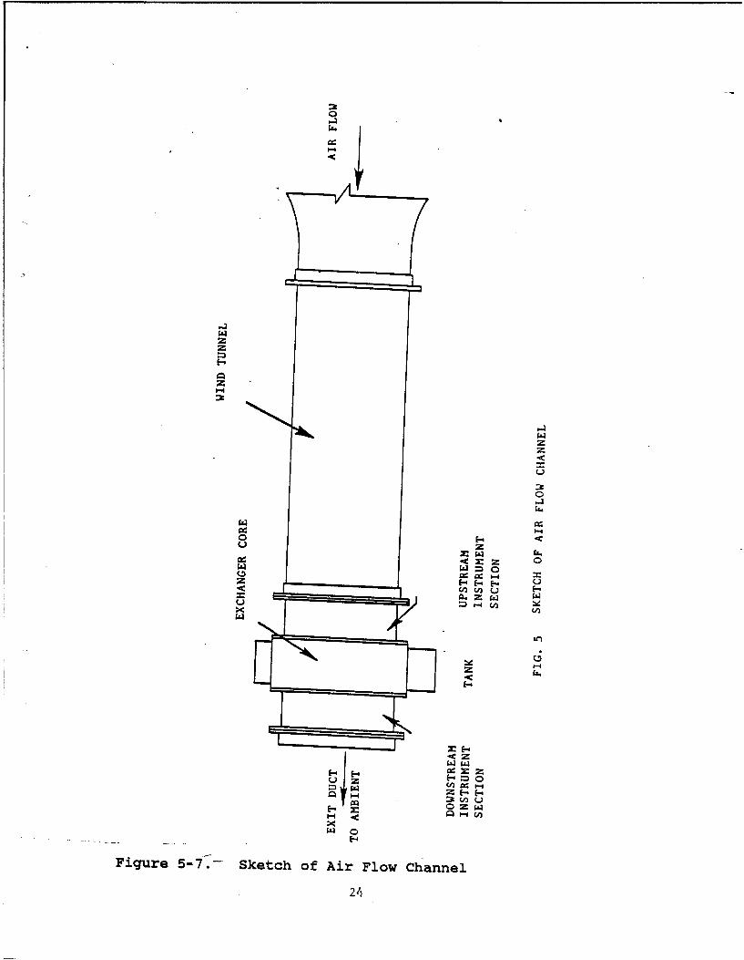
5.3.2. Experimental Apparatus. The investigation wascarried out in an air flow facility in our laboratory. A
21
photograph of the experimental setup is shown in Figure 56.A description of the facility may be divided into twocategories, the air side and the coolant side.
The airflow facility used is an open circuit blowing-typewind tunnel using a centrifugal fan driven by a 5-horsepowermotor. The fan has a maximum rated capacity of 3500 cfm anda head of 6 inches of water. Since the motor is a constantspeed-type, the airflow rate is controlled by a combinationof dampers and inlet guide vanes. Figure 5-7 shows thegeneral configuration of the tunnel.
The downstream end of the test section consists ofinstrumentation modules, between which the heat exchangercore is installed. These instrumentation sections aredesigned to accept measuring instrument probes on the topand one side.
As shown in the schematic in Figure 5-8, the coolant loop isa closed system for circulating hot coolant through thecoolant chamber. Coolant from the insulated storage tank ispumped through the core coolant chamber by a centrifugalpump.
The piping consists of 1-inch galvanized steel pipinginsulated by 1- to 1.5-inch fiberglass insulation. A 10-kWelectrical heater is provided in the tank to maintaincoolant at the desired temperature while the coolant passesthrough four tubes. The hot coolant, approximately at180 0 F, passes through a flow control valve and enters thetank of the heat pipe heat exchanger through a variable areaflowmeter (rotameter). The cooled water leaves the heatexchanger and returns to the storage tank.
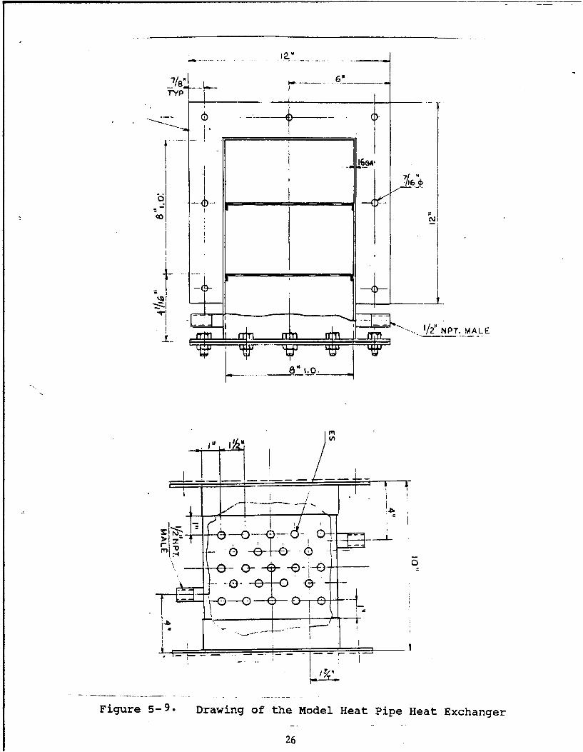
The heat pipe heat exchanger consists of a coolant chamberconnected by heat pipes to the frame. The typical test coreis shown in Figure 5-9. Aluminum flanges were attached tothe frame with screws so that the core assembly could bemounted between the instrumentation modules.
The data measured included inlet and exit air temperatures,inlet air velocity, upstream and downstream static pressure,inlet and exit coolant temperatures and coolant flow rate.
5.3.2.1. Air Side. Inlet air temperatures were measuredusing two copper-constant thermocouples. These twothermocouples were traversed horizontally across the testsection, 6 inches vertically apart. The thermocouples weremounted in stainless steel tubing attached to two traversingactuators fixed to the inlet side module.
22
Ai
S.
Figure 5-i> Photos of the Experimental Rig and the ModelHeat Pipe Heat Exchanger
23
0:
Cz
zz
W W
E-4z
EC-
o E-~E-
Figure 5-71-- Sketch of Air Flow Channel
24
• - INSULATED.PUMP STORAGE
STANK
rHEATER
FLOW CONTROLVALVE
VARIABLE ]AREA co
T.C. FLOWMETER
TEST EXCHANGER
T-T.C.,
Figure 5-8.-- Coolant Flow Circuit
25
7/7/.. p -- -•
6 --
-( - ----------
6" 1.0.
_# I".j* ,
I 1-
"\, -0-- 0
itI
Figure 5-9. Drawing of the Model Heat Pipe Heat Exchanger
26
Exit air temperature measurements were made using similarthermocouples. At the exit side, there is a wide variationof air temperature from the top to the bottom, and it isnecessary to sense the temperature distribution. This wasaccomplished through averaging across the channel.
Pressure measurements were taken at the two instrumentationmodules and at the instrument port upstream of the gridlocation. At the upstream instrumentation module and at thepoint ahead of the grid, the total pressure and the staticpressure were measured using two pitot static probes. Theseprobes were mounted so that they could be traversed to thecenter of the test section when the measurement was to bemade. The inlet air velocity was calculated using the totaland static pressures measured at these locations. Since thevelocity was not uniform immediately downstream of the grid,the pressure measurement at the inlet was used for purposesof mass flow measurements.
A static pressure probe was used to measure the outletstatic pressure at the downstream instrumentation module.In addition, the inlet and exit static pressures wereindependently measured using static pressure taps located atthe center of each side of the instrumentation modules.
5.3.2.2. Coolant Side. The inlet and outlet coolanttemperatures were measured using copper-constantthermocouples. Thermocouples mounted in stainless steeltubing were positioned at the centerline of piping elbowsjust before entering the top tank and immediately afterleaving the bottom tank.
Coolant flow rate was measured using a Brooks rotametercalibrated by weighed discharge as a function of time.Atmospheric pressure was obtained using a mercury barometer.
5.4. Results and Discussion:
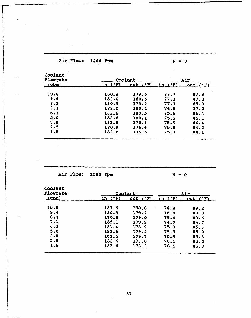
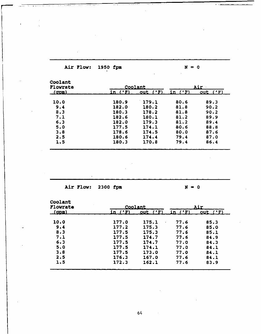
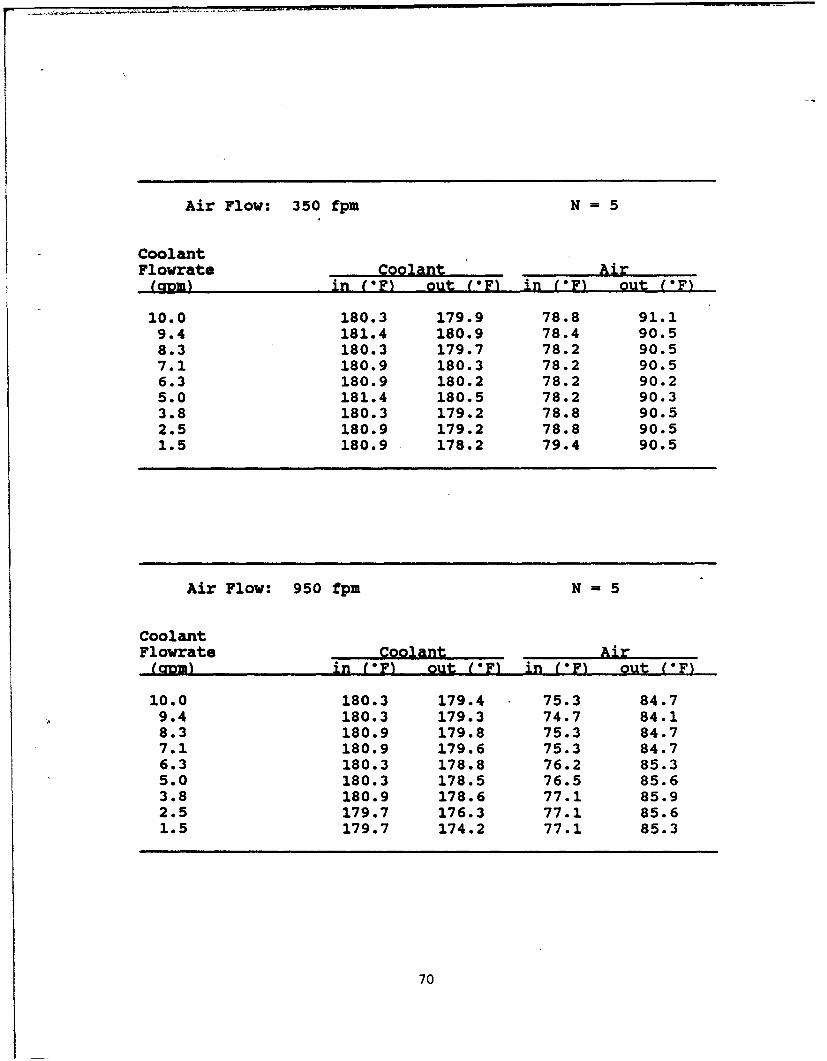
The computer program was used in designing the optimum heatpipe heat exchanger for a design heat duty of 10,000 Btu/hr.The design parameters such as the diameter, length andoperating temperature, of heat pipes along with theexchanger variable including the transverse and longitudinalpitch are obtained as part of the optimization process. Theheat exchanger was fabricated according to the optimizedvariables. The heat exchanger was tested for maximum heattransfer capacity and tested for performance against a rangeof variables. These are as follows:
* Air velocity from 300 - 3100 fpm
27
"* Coolant flow rate 2 to 10 gpm
"* Heat'pipe damage simulation 0,2, and 5 heat pipes
"• Heat pipe orientation.
The air flow around the pipes and its velocity control theheat transfer coefficient, and hence the heat rejected bythe heat pipes to the environment. This is also true in thecase of coolant, only that in this case, higher flow ratesinduce an increased heat transfer from the coolant to theheat pipes. Also, one should remember that superior thermalcharacteristics of coolant warrants a much smaller surfacearea and velocity to transfer loads.
The battlefield damage to a tactical radiator is quiteunpredictable. With that in view, all experiments wererepeated for 1) a full complement of pipes, 2) with twopipes damaged, and 3) five pipes damaged. This representsmore than 20% of the total pipes installed in the modelexchanger.
The damage was simulated by replacing specific pipes withaluminum rods. Even though, under real conditions, thepipes may be cut, still they offer resistance to air. Theballistics were assumed to come from the side, althoughshrapnel from exploding shells could cause random damage.
In anticipation of possible installation problems, some heatpipes may have to be installed with the evaporator sectionover that of the condenser. The performance of the pipes,and by extension, the model heat exchanger, will be quitedifferent. To analyze this situation, experiments wereconducted by rotating the heat exchanger upside down. Thedata were taken over the complete range of air flow/coolantflow rates. In addition, the exchanger, in thisorientation, was performance tested for vulnerability due todamage.
Wherever applicable, the experimental data are plottedtogether with the analytical curve, in order to facilitateeasy comparison.
Figures 5-10 and 5-11 show the performance curves of themodel heat exchanger as a function of air velocity. As wewould expect, the increasing heat transfer coefficientcontributes to a higher capacity up to a velocity of 2500fpm before leveling off. The agreement between theexperimental data and the computer generated curve shows thecorrectness of the computer program developed for model
28
o0 0( 0 t0
0 MV)0 W
,W III
1.0 E 0j
0~C Cl EO , **
ii 0>00
0e F U) 00 Wi
239
...0 0>•
04
C; 0)440
40 0 a.
00W
"q 0) LL
C'J~ 000 J
Figure 5-1.Effect of Damage on Heat Pipe NetworkWater Flow - 10 gpm
29
0
.0 COra
4 -4
0
o010 C)V
Ca)
.4 'Cy0'-
-~ 0 0
'., 0- 1.1.,
I CY
S', 0 r
4-40 0"
C~E w00
0-~T E~LJ
0 0 t CoC 00L0 0 O Oto
% WE0 >W
0 >
a0 F -W
0
0 W
0~ la0".4
0rW410L.L.
eCJ 0 CO C 0
Figure 5-11l Effect of Damage on Heat Pipe NetworkWater Flow - 5 gpm
30
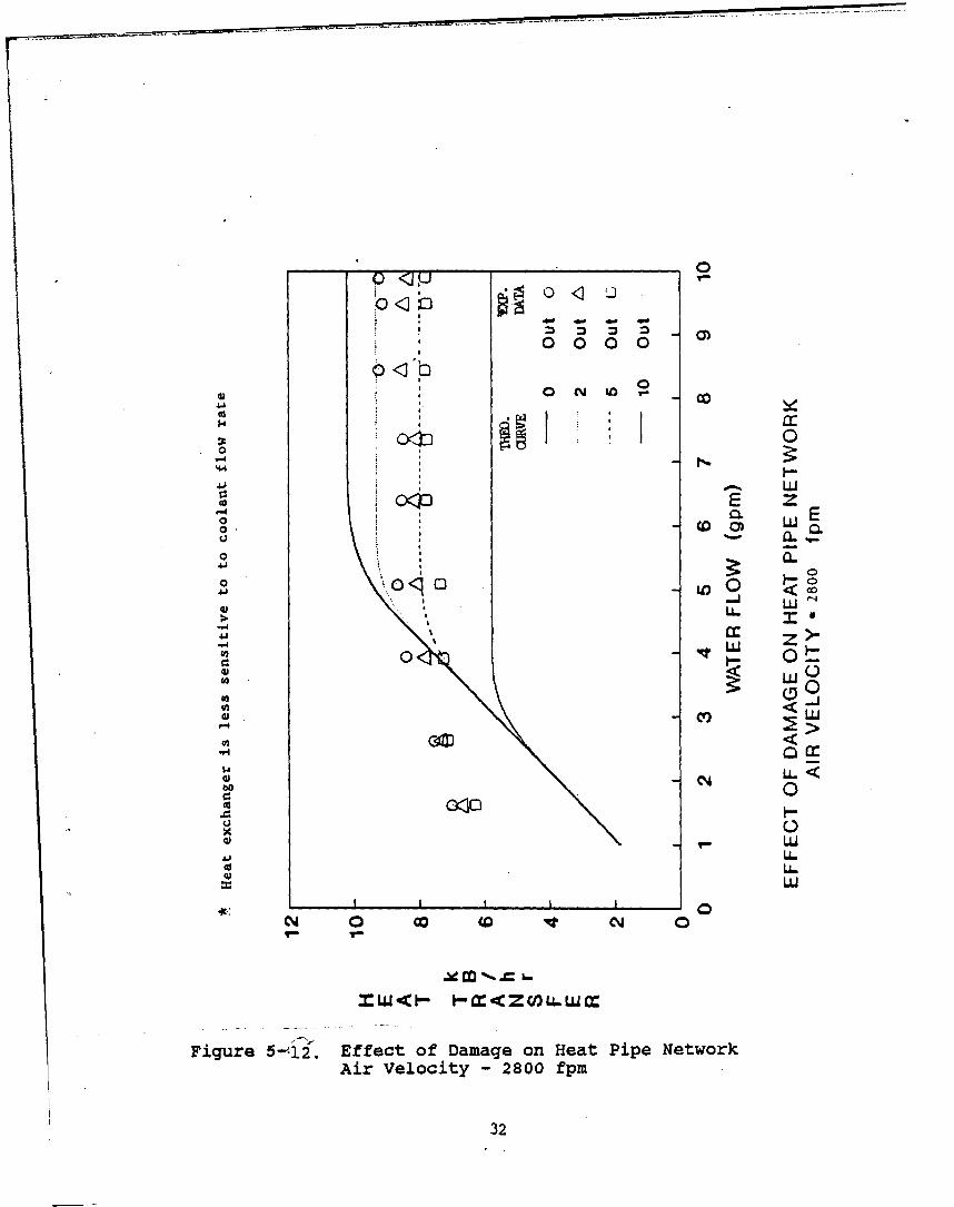
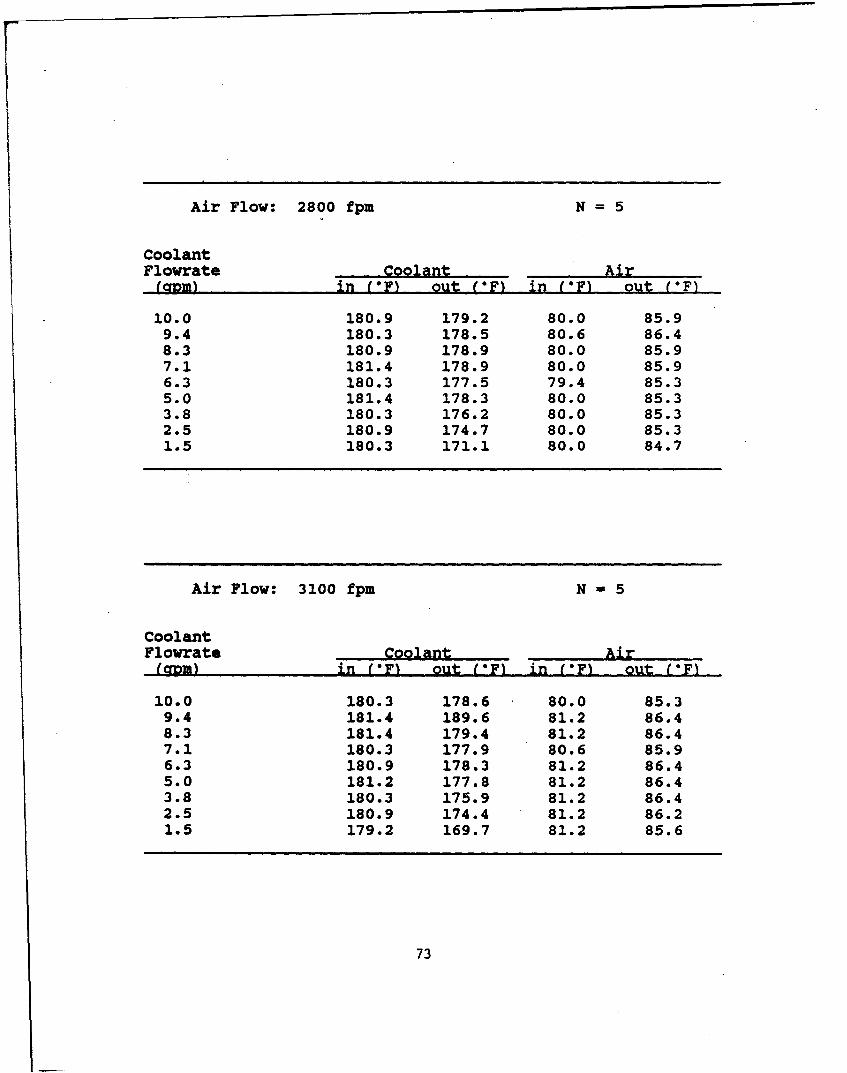
design. The curves for damage simulations, too, agreeexcellently with estimated values. At 10 GPM (see Figure5-10) the evaporator section was able to absorb the ratedload and the pipes were operating at near capacity. Theremoval of pipes do not impede the performance greatly. Forinstance, with 5 out of 23 pipes damaged, the performance.reduction was around 15%. The curves for 40 % of thedamaged pipes indicate the exchanger can still operate atmore than 50% of its rated capacity.
When the'coolant flow rate is decreased to 5 GPM (see Figure5-11), the heat capacity of the fluid is still large enoughto deliver a thermal load of nearly 10,000 Btu. (Of course,the coolant outlet temperature varied correspondingly.) Itis easy to note that the load delivered by heat pipe networkmodule was still increasing even at 3000 fpm, indicating theapparent restriction posed by heat input by coolant.
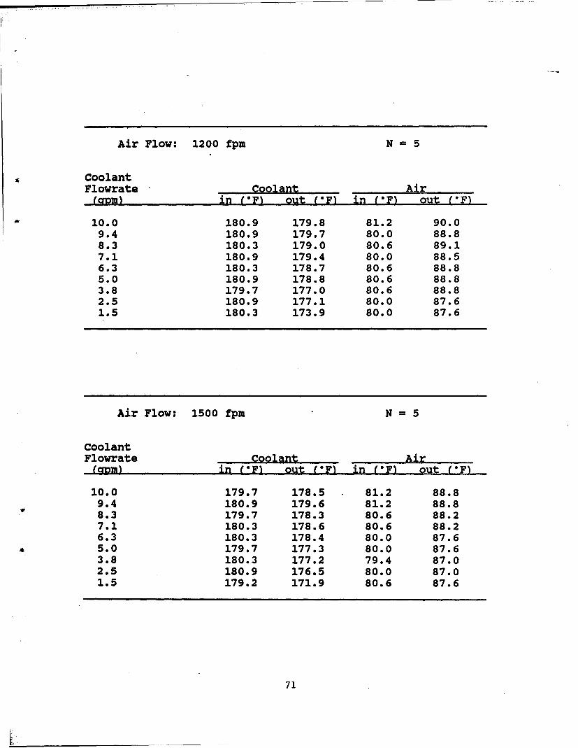
The constraint posed by the heat input is clearly seen inFigures 5-12 through 5-14. The curves show the heattransfer rate as a function of coolant flow, this time withnear constant heat rejection to air. The module reaches itsrated capacity only for flow rate > 7 GPM. This explainsthe rising trend exhibited by Figure 5-11. The data agreewith the trend shown by the theoretical curves. The slightscattering of the data at low GPM is not uncommon and can beattributed to fluctuations in flow. Another noticeablefeature is the flow rate at which the heat transfer becomesindependent, decreases as more and more pipes are removed.The operating capacity of the severely damaged exchangermodule can be expected to operate at close to 60 % capacity,with even a reduced liquid flow rate of 4 GPM.
The thermal capacity of the module reduces when therejection rate is fixed at a lower level at Vair = 1500 fpm(see Figure 5-13). The data fall below the computed curves;however, the difference is below the experimental error.The plot indicates a reduction in capacity of 20% when airvelocity is reduced from 2800 to 1500 fpm. Furtherreduction in air velocity 950 fpm (see Figure 5-14)decreases the heat exchanger performance by another 25%.Also, higher liquid flow rates (greater than 5 GPM) do notcontribute positively to the performance.
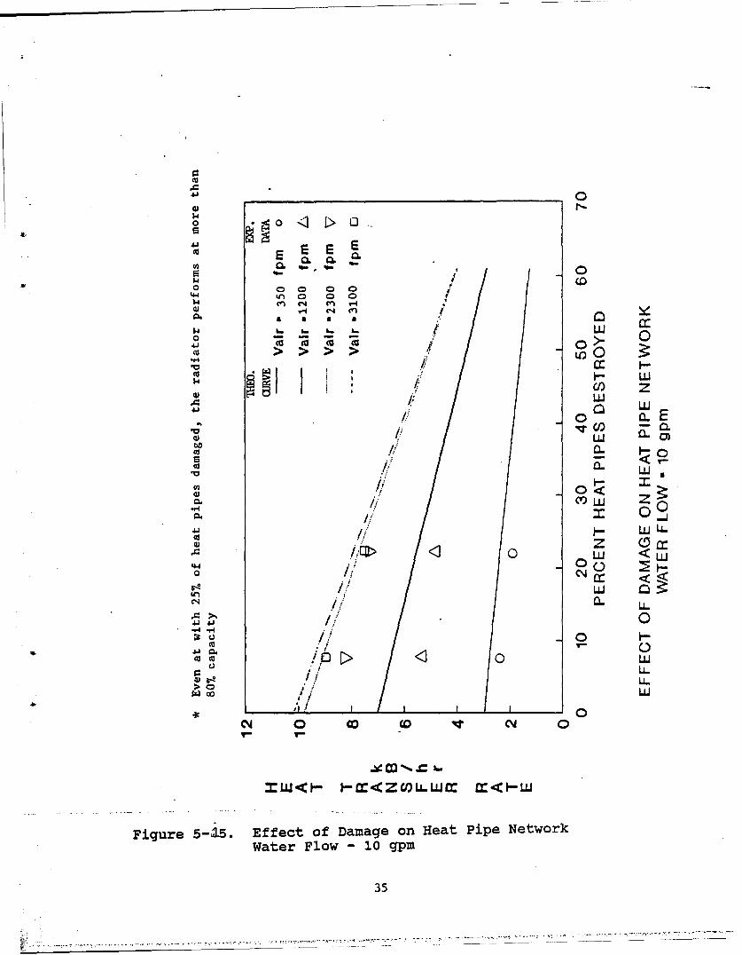
The tests on damage simulation were conducted intuitivelyfor two specific cases. Continuous curves were drawn bymodifying the program and the estimated plots were checkedwith the available data for the two cases. With liquid flowmaintained at maximum rate, the various vulnerability curvesshow that the performance reduction is more gradual at lowerair velocity than at higher airflow rates (see Figure 515).
31
0)0K~ 0
0000
SO OO CO0 zH * I
0
4)
00
o •
S• LLI
0*0
o <
",. >
-GO
otcc
.U : I I ,
U,-
0 0- C' LU
U)-
H ~LL
Fiur 0-,i feto aaeo etPp ewr
Air Veoit-80 p
U (32
o :oO.00000
0 0 0 0
0 CI LO v- G
ý4c.00C I
° o o n.4)
. C-
001.. LU
U..
oz
W" 0
4 IL 6
00@00 C,,•
< )
a:00~
Fiue5-34fec.fDmaeo4Ha 0e ewr
I..
A..LU
0 0 0 C4D 4 C 0
Figure 5-13. Effect of Damage on Heat Pipe NetworkAir Velocity - 1500 fpm
•33
- 0
I0 <o U0 0
0- 0 -4U
0000
$4
q<c C) 0
0 0. wE0.. ~~zoE
cca 4
QC
0) L0
0-W 0U
<LU00 0<0
0U
C.))
Ca0< 0 2>Q. <
LL
0)0
0) LL
-ItI
N (0 CO, C 0
Figure 5-14. Effect of Damage on Heat Pipe NetworkAir Velocity - 950 fpm
34
1.4
o0
sEI 0
.,o 00 00! o
a a .
L. L. .. LU o0 0J0
*1. Ii" ,.
,I I I- L
> > > ) Z
""c L
LUUj
ba
o .a. <_CIUi. 1/ 0'U ~ . .,
"U)
0<
<,! / n u
J-)j LULJ/ z Q!J
"4 ! > 0 LUJ
0~0
o ,! ti0 ~ LU I
C.. ,' ..
0 1-
CU / 0
<4 0 CO 0M 0- ji~ . l-Li..l• • t ~ .- i
V h
Figure 5-,15. Effect of Damage on Heat Pipe NetworkWater Flow - 10 gpm
With sample data matching well with the curves, it is safeto say that the exchanger will continue to perform at 20 to50% of its rated capacity with as much as 50% of the pipesdestroyed depending on the air velocity.
Reduction in liquid flow rate on the module performance isnoticeable for higher V ir of 2300 and 3100 fpm (see Figure5-16). Comparing with tie curves on Figure 5-15, it isclear that module operates somewhat less than 10,000 Btu/hr.But it maintains the performance at the same level with oneor two pipes damaged.
Figures 5-17 and 5-18 show the same results in another form.Here we can observe that the combination of higher liquidand air flow rates, while transferring the rated capacity ofheat, produces a drop that is steeper than at lowervelocities.
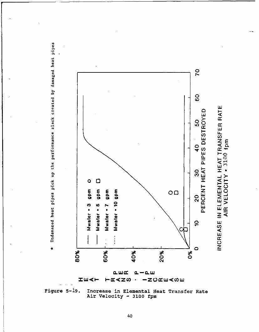
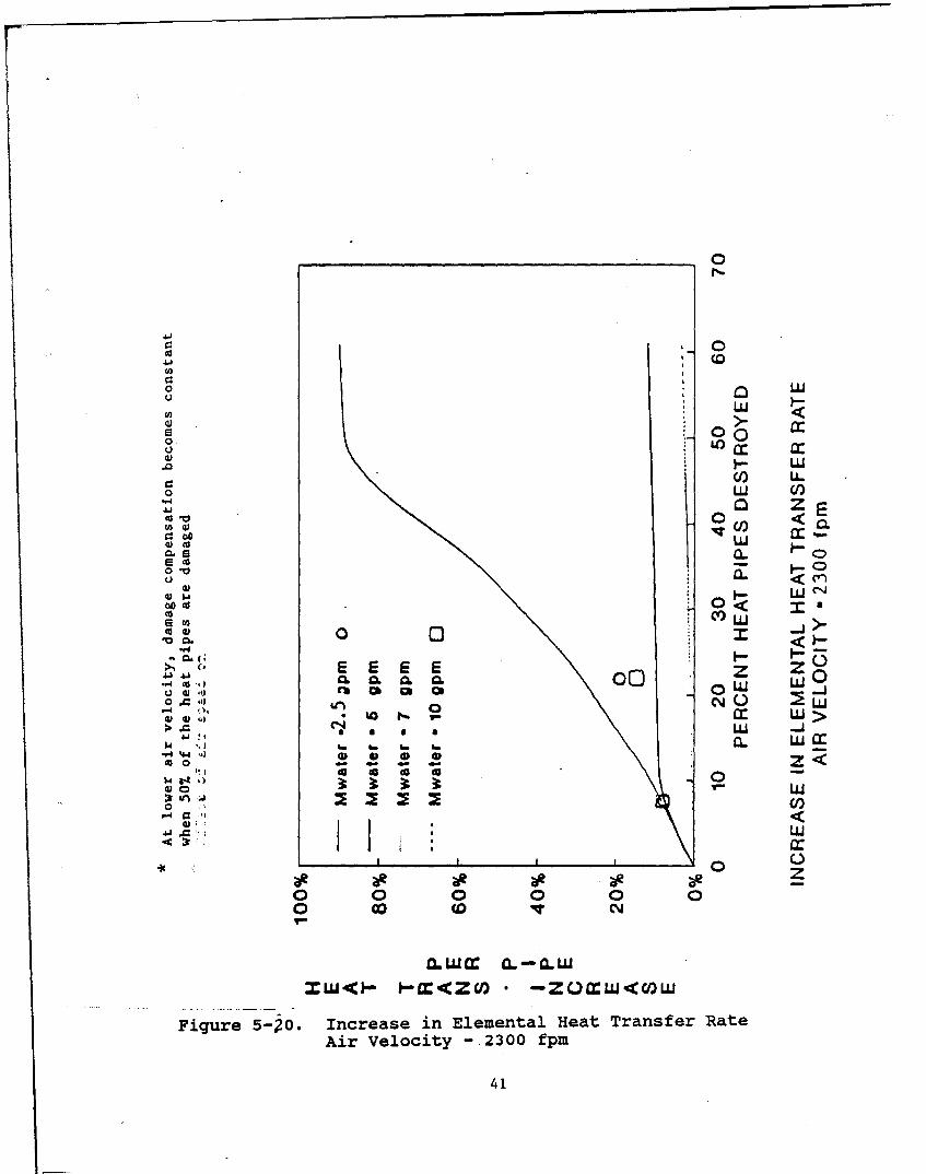
A unique characteristic of any heat pipe network is thatshould some of the heat pipe ease to work, the remainingelements increase heat duty. This, however, is noticeableonly if the heat pipes are operating under the maximum limitset by its elemental design. This can be seen in Figures5-19 through 5-21. For example, in Figure 5-19, the pipesare already operating at near the upper limit (V i = 3100fpm, G - 5 to 10 GPM), the increase in individual -eat pipecapacity is very small. But when heat exchanger isoperating at lower (2.5 GPM) thermal loads, the heat.transfer by a single pipe can increase as much as 70%.Caution should be exercised in that this value is still wellbelow the upper limit set for the heat pipe. Thischaracteristic is exhibited for any air velocity (seeFigures 5-19 through 5-21).
Heat flux characteristics are shown as a function of the airvelocity and increase in heat flux is minimal at high GPMand air velocities for reasons cited previously. Althoughheat fluxes are nearly the same, it should be pointed outthat the net load decreases with damaged heat pipes (seeFigures 5-22 and 5-23).
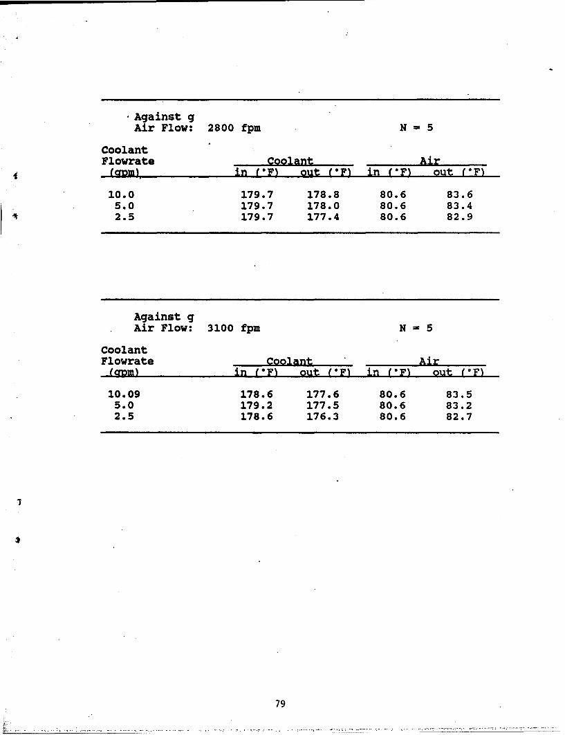
The heat pipe operation depends on the inside fluidcirculation and this is sustained by capillary pumping andthe gravitational force, which may aid or obstruct efficientoperation. The data and the curves shown so far aregravity-assisted heat pipes.
When gravitational forces act against capillary forces, someof the pumping is lost and the heat pipe operates in anentirely different level.
36
0
o1~D
SE E E
0 00
S> > > > b 3
io W
CO z
m0 00. 0
CO aW •D
o 0>
WI
00 W
•w
Watr4Fow 5Wgp
30700
/ WLL
0 W4U
00 / LI-
LL..W
CY 0 00 (0 I 4 0
Figure 5-~16. Effect of Damage on Heat Pipe NetworkWater Flow - 5 gpm
37
00
4W in 0(
r. to 0-
0 0
-. I a.' W
0 W 2
0U14 0.
00<0 OW 0<
0.0
0<10 0 Wa).
a.O LL.(Uj
CM 0 D ( W C
1-X<W.W xV 0 I--
Fiur 5-70feto aaeo etPp ewr
Ai Veoit 230wp
38-
0
o 0
43), 0
UL 0
00 >- 0U-0 0 3a
cc~43)J
LwjE00 a
.9O W
0<0A bs
Cd UJ0
00-S 9-.. .
000
0- W44
0 I
CY0 W O W 9T C
Figure 5-I8. Effect of Damage on Heat Pipe NetworkAir Velocity - 1250 fpm
39
00
00
a)j
cc_ _ _ _ _ _ _ _ _ 0 0
a)'
00
io
a.-
U.J00><
E 6 z L
03 L..
044 oL
0. LL
I-.
0~ 6 z
aR aR a. aR a
0 0 0
- <- ýXZo- - zQrL<O
Ai Veoct - 310 fpm
04
r I , O4j1
0 U0Co
o Q LUn LL.
00
L<C(A v ) CC.
LU
o + .• * o e, , r" 111
< C-
5co C4)W
- I :U.
E 2 000 0
0~ wg -j
- ', 1- LU>- .LI,
'0 C*
"Il.l..l.l,< ,, I'- &. -Z ~ •U 0.,
0 0ccc - >
0* 0 -
Ow 1ýt
x in
0 0 0 0 0 00 Go W IVJ
)O.LAJZC O- -~xA.W
Figure 5-ýo. increase in Elemental Heat Transfer RateAir Velocity - .2300 fpm
41
UU
0 0-41 LU
-4 04.' LU
00
(I)
CL
LU
<(N
* 00z
zQ 00E E EE Z L> ~0.C.0a.0.L
Ln C'4 L LU >
0CLd)/
I LU
4 0
o 0 0 0 0 0 0(D U) I V) N
W'(- -X~Za * -ZOQWLL<C)LU
Figure 5-21. Increase in Elemental Heat Transfer RateAir Velocity - 1200 fpm
42
00Z) 0
00Ca,
COO
:00
00 0E z\O0L
0-0WW boIa. v CID
,-40 U)J-4 00
i > 0 -0
0JJ 0000_JLL.
00 000
N4 wWO 00 U.a, 44 LL.
,00
C O Crw- ~-F-= 0 M (4O C C'O CO#
xW<(I- W.J:x
Figure 5-,ý2-2 Effect of Damage on Heat Pipe NetworkWater Flow - 10 gpm
43
.'0
-4U 0
0
000 0
00W
00 S\ "a 0
•a a0
t 0 C) < to0
to '
0
U)U
Wae Flo -j LLg
4 04
00
0 <LL
4.a.
CU.
to 0Y10
oX Li....
Water Flo - g
44
In Figure 5-24, a substantial reduction is shown in theoverall capacity of the heat exchanger from 10,000 Btu/hr to4,200 Btu/hr even at high air velocity (3,000 fpm) andcoolant flow rates (10 GPM). The agreement of theexperimental data with the theoretical estimates can be seenfor both the full heat exchanger and with five pipes out.The behavior or the trend of the curves is quite similar tothat exhibited in earlier curves that were drawn withgravity-assisted pumping.
A reduced heat input through a lower flow rate of 5 GPMresults in almost identical curves (see Figure 5-25). It isbecause the heat pipes are working at maximum capacity evenat flow rates less than 5 GPM. So any attempt to increaseheat load through higher air or liquid flow rate will befutile. However, it must be pointed out that the onlyrestriction is placed by the heat pipes since neither heattransfer coefficient nor the temperatures are affected bygravity.
Figure 5-26 shows the effect of airflow rates on pressuredrop and heat transfer. The heat transfer characteristicswere already explained previously (see Figure 5-10). Thepressure drop behavior is as expected for a typical crossflow heat exchanger. The pressure drop increasesexponentially with air velocity. We should recall that evenwith damaged heat pipes, the resistance to air flow remainsthe same.
The performance of the heat pipe heat exchanger module wascompared with an equivalent conventional heat exchanger.The only difference between these two modules is thereplacement of the heat pipes with the same diameter and theaddition of a header at the top.
A proprietary cross flow heat exchanger program was used inthe performance analysis of this heat exchanger and theresults are compared with those of the heat pipe module (seeTable 5-1).
As before, coolant and airflow rates were varied. The heattransfer capability of the heat pipe module is higher by upto 25%. At higher air and coolant flow rates, thedifference is much greater. It may be expected that for aprototype radiator, the operating conditionsnotwithstanding, the performance will be even greater. Thisis because the coolant flow rates, as well as air flow ratesresult in higher Reynolds number and, by extension, heattransfer.
45
0
04
00
U44
" 0
> 0 Z
. \ N a.•
C~C)00
"o .°> Z 0.0 0
03 I0I.
W 0
I 00
WaOo - ga
3..
0
Water0 Flw-10gm(gantg
X 06
0
$4
10o, 0
"0cc
0 O
en ,
4.4
o 0 2
0 U) W
ICI
ao ' 0J
W a
Water~~- Flo b-0pm(gintg
C) W
cc. U.UW
00"-f 14 0 ~ z
4.) 44)\
CO ~0<
447
b,- 00 0
02C0
0c W
U-
Figure 5-.25. Effect of Damage on Heat Pipe NetworkWater Flow -5 gpm (against g)
47
*Pressure drop trend is similar to that of a cnnventionalCross flow heat exchanger
12
WATER FLOW = 10 GPM11 Tair,in = 70 F
Twater,in =180 F DAMAGED HEAT PIPESDIA. =0.5 in N=
A CONDENSER = 8 in10 EVAPORATOR = 4 in
NUMBER OF2
S9 HEAT PIPES=23
• 8 61.4•
S7 1.2 L
00
'• 5 0.8
• 4 / •b PRESSURE 06
" I/ DROP
3 0.4
C/
l 0.2
0
0600 1200 1800 2400 3000
S~AIR VELOCITY, ft/min
Figure 5-26. Effect of Air Velocity on Heat Transfer and pPressure Drop
48
0."4 CA C41 cVn U, V-4 4 4'w 0 Go 04 04 Go 00 c
co 041 r-4 r- 0 04 C14 CN4C41 04 In 0 Go co co co bO0d 04) w
1.4 bo
C0 bo~ :3C
00 co CA G '0 0% 0 * C% co 0% Ccn ,-4 %0 4 % "4 " rj j 0% 4 Go cn (A .4 0 C.44~4 w4 C)d4 * , 0 '
0 Cd 0
o9 0k"4.) "4
"04- cln 0 "4 r%ý 04 P r- w k o.)r-. %0 rl% co in 4 %.0 4) ;0m 00 0~4 0 w-4 '0 P- %.04J. 04 4 in '.0 Ir. - r- r 4 0
0 C)
ra 0$4 144
OO1 r- 4 % CO) 4 '
'H.%. 0 cn -.0 co Mn 0 w. 'D.0"I: xn 4 n in 'D '.0
~4) bO c00Cd0 0Q0 4)w n 0
0 0) 0"q 4 04. r- 00 en 04 04J N.ow. .0 C0 It (A 04 C~4 C4.l . 41
41 44 0% C" 'J in In An 4M 4 44.c4d n , ~ U 4) 14)
"444
0 cd 0"4 "4"U4 A A'M c 0 C'4 r"4 4 in %'04j .) U C14 "4 %D0 "4 Co co "-4 P-,k48 0.'m "4%0 V- 4 0 I'- "-4 ..4 '.44)J Wn M 4 U '0 '0 r,~4. 1.4
u )0
0.0ý 0 0 0 0 0 0 0 0U, UL L 0 0 LM 0 0 004 in 04 V)l CA 0% n co "-4
w 4"r4 V"4 "-4 Cl4 C4 cn
49
It may be stated with caution that a heat pipe radiator forsimilar loads can result in size and weight reduction.
The experimental data for the various tests are given inthe Addendum.
"* The experimental data are in excellent agreementwith the theoretical curves, except at very lowliquid and air flow rates which may be attributed toflow instabilities.
"* Heat input effect is more pronounced; however,similar to air velocity influence, the performancebecomes independent after certain critical liquidflow rates.
"* The capacity of the module decreases with heat pipe,when the module is operating at high capacity.
"* At lower thermal load, loss due to heat pipe, wascompensated efficiently. With 30% of the pipeslost, the output from the remaining heat pipesincreased by 40%. Yet, the individual heat pipelimit was still lower than the design upper limit.
"* Against gravity, the flow rate did not have muchliquid impact except at rates less than 5 GPM.
"* The air flow rate increases the performance lessgradually against gravity. Working againstgravitational head, the decrease in thermal load wasproportional to the percentage of damaged heatpipes.
In previous discussions it has been shown that the heat pipeconsists of an evaporator section and the condenser section.For truck radiator applications, the evaporator section isplaced in the hot coolant and the condenser section is sweptby the air stream generated by the fan and the motion of thevehicle. The heat pipe is a self-contained closed system.These simple observations show that only one coolant headeris required. The coolant will sweep the evaporator sectionand the air will receive the heat during flow over thecondenser section.
By comparison, in the conventional radiator hot liquidenters the header at the top, flows through a bundle oftubes (downcomers) losing waste heat to cooler flowing air,
50
and is collected in a header at the bottom for return to theengine.
A conceptual heat pipe truck radiator could then be as shownin Figures 5-27 through 5-29. In this figure heat pipes areshown configured similarly to the coolant downcomers of aconventional radiator. A single coolant header is provided.This header could be armored or protected by the bumper ofthe vehicle. The radiator is then catastrophicallyvulnerable (capable of losing the entire engine coolant)only in the case of breakage of the main header orinlet/outlet hoses. Hits in other areas will only destroycertain heat pipe sections. It is seen that the area ofvulnerability has been reduced significantly from theconventional radiator coolant tube configuration.Obviously, the entire engine coolant can be lost from aconventional radiator with a penetration in the top header,bottom header, and any coolant tube.
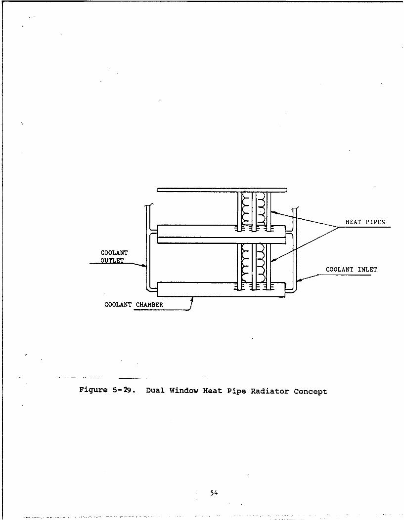
During Phase II, further testing will develop practical heatpipe configuration factors, such as length, shape, spacing,etc. A short condenser section requirement couldsignificantly reduce the required length of the heat pipe.In this case, shorter heat pipes could be used. A potentialconfiguration in this case could be as depicted in Figure5-29. Two rows of half length heat pipes are shown usingseparate coolant headers. Each header could be armoredagainst catastrophic failure.
More effective heat pipes could also reduce the sizerequirement (area) of the radiator, reducing vulnerabilitycross-sections. More advanced heat pipes using arterialwicks will lower the number of pipes required for similarconditions. Some possible alternative heat pipe designsthat could be used are shown in Figure 5-30. Alternatively,by maintaining the same area as the conventional radiatormore effective performance would be obtained and any pipeslost due to battle damage would result in less loss ofcooling load. In this situation the radiator would becapable of sustaining a larger amount of battle damage. Thetradeoffs necessary to make these judgements are complex andrequire the detailed data that would only be availableduring the Phase II effort.
This Phase I effort demonstrated the feasibility of theconcept. Design parameters that are requred for tradeoffstudies can only obtained from further testing and analysis.Operating conditions such as ambient air, less than 32°F andgreater than 120OF should be taken into consideration. Heatpipe and radiator design, including consideration ofalternative working fluids, will be taken into consideration
51
HEAT PIPES
HEAT PIPES
000000000
Figure 5-27. Possible Heat Pipe Arrangement
52
SUPPORT BRACKET
HEAT PIPES
THREADED EVAP TORCOOLANT INLET
OUTLET
Figure 5-28. Single Window Heat Pipe Radiator Concept
Figure 5-00. Geometric Arrangement of Wick Channels
55
in more detailed work beyond this "proof of concept"demonstration of a heat pipe network radiator.
This Phase I effort has demonstrated the feasibility of aheat pipe network to be used in application to a truckradiator. It has been shown that a heat pipe network can beaccurately sized to meet a design cooling load at conditionsapproximating those of engine cooling. Furthermore, it hasbeen shown that cooling load can be maintained with numerouspipes out of service such as could occur due to ballisticimpact in a combat environment. By totally inverting theheat pipe matrix, it has also been shown that cooling loadcould be maintained at high slopes such as could beexperienced in combat terrains.
Also, performance tests on the heat pipe network with wateralone and 50/50 coolant glycol mixtures produced similarresults that were within the experimental error.
Heat transfer capabilities of the heat pipe network havealso been compared with those from a coolant system withgeometry similar to the experimental configuration. Theheat pipe network results in an effective 20 to 25%increase in heat transfer for the same geometry. Thisresult shows the ability to lessen the area requirement forthe radiator or to provide increased damage sustainabilityfor the same area as the conventional coolant radiator.
This Phase I concept feasibility study has verified thethermodynamic capabilities of the net pipe network concept.Much more detailed analytical, experimental, and designstudies are required before precise cost-benefit tradeoffscan be made as to adaptability to the Army requirements. Afew observations can be made however, as a result of thestudies conducted to date assuming that the final designapproximates the conceptual study.
The chief modes of radiator failure, aside from ballisticprojectile impact, are corrosion, fouling, and damage fromforeign objects. The heat pipe radiator would have lesssurface exposed to the aerated corrosive cooling coolant.The only corrosion areas would be the external walls of theheader and the surface area of contact between the hotcoolant and the evaporator section of the heat pipe. Theheat pipe itself is likely to be manufactured separately asan assembly and would use pure working fluids that would becorrosion proof to internal corrosion.
External fouling is due to dirt, mud, and engine oildependent upon the manner in which the radiator installed inthe engine compartment. Various configurations are possible
56
depending upon whether the compartment has positive ornegative pressure. The test results to date have shown theheat pipe radiator to be potentially more efficient than theequivalent coolant radiator. With this potential availabletube spacing could be opened up providing more air passagearea. This could potentially reduce the tendency ofexternal fouling.
The heat pipe radiator would also likely survive andcontinue to provide engine cooling even after damage toseveral tubes by rocks, branches, and other foreign objects.Conventional radiators would eventually lose all the coolingcoolant even in the event of small penetrations in a tube orheader.
Elimination of the other header (bottom header in theconventional radiator) would result in less cooling watertotal volume. This would also save coolant in combat butwill also save glycol throughout the Army operational andtraining missions. Filling of the radiator and assuring noair pockets will be assured with the one header system andthe closed cycle heat pipes. Conventional radiators attimes lock the flow so that added coolant does not flow downto fill the downcomer tubes. In some instances, it isrequired to run the engine for a period then refill theradiator to insure complete filling.
With a proper design it is also possible that individualdamaged heat pipes could be easily replaced. This wouldmake field repairs much easier and could save on the need tostockpile entire radiator assembly for replacements.
Precise determinations on this matter will, of necessity,require a design close to the final one, such as will beattained in Phase II work. Conceptually, though, severalpossibilities could be postulated. The cost of the totalradiator is likely to be controlled by the cost of theindividual heat pipe elements. With volume production thesecosts would be significantly reduced from those used in theexperimental test program. Taking advantage of the higherheat transfer ability of the heat pipes could also reducethe total number of elements necessary for incorporationinto the radiator assembly, also reducing costs.
With the one header system, the number of braisingoperations could be reduced by about half compared with aconventional two header coolant downcomer radiator. Thecondenser ends of the heat pipes could be clamped in asupport bracket and may not require braising.
57
It appears that, dependent upon the final designconfiguration that costs for the heat pipe radiator, inquantity could approximate those of the conventionalradiator. Should the manufacturing costs be higher for theheat pipe radiator, it may be that when the combatoperational benefits of the improved invulnerability arefactored in that these costs could be justified.
5 "Cooling of Detroit Diesel Engines," General MotorsCorp. Detroit Diesel Engine Division, EngineeringBulletin No. 28 (May 1967)
6 "Engineering Know-how in Engine Design - Part 15," SAEPublication SP-292 (1967)
7 Mascaretti, F.C. and Medana, R., "Diecasting Parts forFiat Front Drive Cars," Proc. 7th SDCE Int.Diecasting Congress, Paper No. 4272 (1972)
8 Winship, J., "Diecasting Sharpens its Edge," AmericanMachinist, Vol. 118, pp. 77-78 (1974)
9 Katzoft, S., "Heat Pipes and Vapor Chambers for Thermal
Control of Spacecraft," AIAA Paper 67-310 (1967)
10 Roukis, J. et al., "Heat Pipe Applications for SpaceVehicles, Grumman Aerospace," AIAA Paper 71-412(1971)
11 Beard, R.A. and Smith, G.J., "A Method of Calculatingthe Heat Dissipation from Radiators to Cool VehicleEngines," SAE paper 710208 (1971)
12 Cool, N.A., "Economic Factors in Radiator Selection,"SAE paper 720714 (1972)
13 Tenkel, F.G., "Computer Simulation of AutomotiveCooling Systems," SAE paper 740087 (1974)
14 Emmenthal, K.D. and Hucho, W.H., "A Rational Approachto Automotive Radiator Systems Design," SAE paper740088 (1974)
59
15 SAE Handbook, Two volumes (1974)
16 Cotter, T.P., "Theory of Heat Pipes", USAEC Ref. LA-3246-MS, Contract W-7405-ENG-36, Los Alamos, NM; LosAlamos Scientific Laboratory, Univ. of Calif. (1965)
17 Busse, C.A., "Heat Pipe Research in Europe", 2nd Int.Conf. on Thermionic Electrical Power Generation,Stresa, Italy, May 27-31, 1968, Euratom Center forInformation and Documentation (EUR No. 4210 f,e),pp. 461-475 (1969)
18 Busse, C.A., "Pressure Drop in the Vapour Phase of Long
Heat Pipes", IEEE-Thermionic Conversion SpecialistConference, Palo Alto, CA, pp. 391-398 (October 30 -November 1, 1967)
19 Kinney, R.B. and Sparrow, E.M., "Turbulent Flow, HeatTransfer and Mass Transfer in a Tube with SurfaceSuction", J. Heat Transfer, pp. 117-125 (February1970)
20 Silver, R.S. and Wallis, G.B., "A Simple Theory forLongitudinal Pressure Drop in the Presence ofLateral Condensation", Proc. Inst. Mech. Engrs., 180(1), pp. 36-42 (1965/1966)
21 Brinkman, H.C., "On the Permeability of MediaConsisting of Closely Packed Porous Interface",Appl. Sci. Res., Vol. Al, pp. 27-34 (1947)
22 Palen, J.W., "Heat Exchanger Sourcebook," HemispherePublishing Corporation, New York (1986)
23 Kays, W.M. and London, A.L., "Compact Heat Exchangers,"3rd Ed., McGraw-Hill, NY (1987)