278 IEEE TRANSACTIONS ON EDUCATION, VOL. 31, NO. 4, NOVEMBER 1988 dents, parents, and representatives from industry, is intended to showcase the creative possibilities in engineering education. With an eye toward the high-school visitors, a video game was written to demonstrate the capabilities of the machine. The “star wars” style video game developed, which is over 2500 lines of code, tests virtually every aspect of the instruction set and interrupt operation. It proved to be a very popular exhibit and was run continuously over the two-day event. As an additional application, a laboratory exercise was devel- oped for succeeding classes of EE 478. Combining the observation of logic and state analyzer traces with a theoretical understanding of the basic design, students are introduced to microcode control, interrupt operation, a variety of different state machine implemen- tations, memory protocol, and general clock and signal timing. CONCLUSION At the University of Washington, computer engineering curri- cula consists of a series of courses which introduce the student to some specific aspect of computer design. Examples include logic systems, microprocessor-based systems, Assembly language, op- erating systems, and computer architecture. In this project, we had the opportunity to integrate all of these disciplines in the challeng- ing “hands-on” environment created by the capstone design course, EE 478, Design of Computer Subsystems. Although each student had designed and built only part of the machine, by the end of the project it was clear the participants had gained a new depth of understanding for all aspects of computer operation. In addition to technical skills, professional engineering in our increasingly complex world most often requires two important in- gredients: teamwork and the application of systematic design prin- ciples. Although far from an easy lesson, this project provided an ample opportunity for us to cultivate both of these abilities. Although we feel that these academic quarters were by far the most taxing and difficult spent at the University, we must acknowl- edge the inestimable contribution that the project has made toward our education, growth, and confidence to function as responsible, professional engineers. We therefore strongly recommend that electrical and computer engineering undergraduates be given the opportunity to participate in this type of team-oriented capstone design experience. ACKNOWLEDGMENT We are pleased to acknowledge the support of the people who have helped make the computer project a reality. The remaining five members of the computer group include A. Chung, H. Hoang, T. McTaggart, J. Poon, and D. Tao. The helpful assistance of teaching assistants T. Alexander and P. Jurgens was greatly appre- ciated. Finally, much debt is owed to the Department of Electrical Engineering for its continual support of EE 478, without which the project would not have been possible. REFERENCES [ l ] Y. Kim and T. Alexander, “A new project-oriented computer engi- neering course in digital electronics and computer design,” IEEE Trans. Educ., vol. E-29, pp. 157-165, 1986. 121 A. S. Tanenbaum, Structured Computer Organization, 2nd Ed. En- glewood Cliffs, NJ: Prentice-Hall, 1984. 131 D. E. White, Bit-Slice Design: Controllers and ALU’s. New York: McGraw-Hill, 1980. 141 J. Mick and J. Brick, Bit-Slice Microprocessor Design. New York: Garland STPM, 1981. [5] J. D. Greenfield, Practical Digital Design using ICs, 2nd Ed. New York: Wiley, 1983. [6] Y. Kim, EE 478 Class Notes, Dep. Elec. Eng., Univ. Washington, Seattle, 1987. 001 8-9359/88/ 1 100-02 Teaching the Structured Design of Interactive Information Systems DAVID F. HAAS Abstract-When students attempt to apply the techniques of struc- tured analysis and design to the development of interactive information systems (IIS), a number of problems typically occur because such sys- tems do not obviously lend themselves to the input-process-output de- scription required by structured analysis and design. These problems can be overcome by showing the students how to develop a conversa- tional view of the system and how to convert it to a global view which displays the standard structure required by structured design. INTRODUCTION Structured analysis and design [I], [2], [6], [7] are widely used and widely taught methods of software requirements specification and design. However, these techniques, as they are presented in software engineering textbooks [3]-[5], are difficult to apply to the design of a large and growing class of software systems: that of interactive information systems (11s). This paper describes an ap- proach that has been found useful for teaching students to apply structured analysis and design to problems of this class. For several years, a one-semester, undergraduate course in soft- ware system design has been taught in the Department of Computer Science at the University of Wisconsin, Oshkosh. The course is an elective for juniors and seniors and is taken by students in the MIS Department as well as those in Computer Science. Students in soft- ware system design have generally been given term projects which they must carry from analysis through design to coding. Good proj- ects are not easy to choose. They must be large enough to be in- teresting and small enough to be completed in a 14 week semester. One kind of project that is attractive is to have each student build a small, interactive information system. For example, one semester the project was to design and build an interactive, microcomputer- based system for home bookkeeping. When a project of this type is chosen, the students repeatedly have problems in learning to apply the techniques of structured analysis and design. The first problem arises because structured analysis and design are based on the idea that a software system is a transformer of data, but students do not see an IIS that way. In- stead, they see it as a system that responds to commands or queries conversationally. The conversational view can be converted into the canonical data flow description, but it is not obvious how this should be done. Conventional descriptions of structured analysis md design are of no help here. The second problem is that, in the students’ view of an IIS, the bulk of the input appears initially to consist not of data, but of control information (commands or queries). Structured analysts recommend strongly that one should not concentrate on control in- formation, but on data. So, a way must be found to handle the (obviously important) command stream with the tools of structured analysis. Closely related to the second problem is a third one which has to do with the role of the internal files maintained by an 11s. In order to respond conversationally to queries or commands, a sys- tem must maintain its own files. They play a special role in an IIS because they are hidden from the user, and input from them is not input to the system. Handling the internal files properly in the framework of structured analysis requires some change in the usual portrayal of data flow and a considerable change in the time per- Manuscript received March 7, 1988. The author is with the Department of Computer Science, University of IEEE Log Number 8823 111. Wisconsin, Oshkosh, WI 54901. :78$01.00 0 1988 IEEE
Transcript
278 IEEE TRANSACTIONS ON EDUCATION, VOL. 31, NO. 4, NOVEMBER 1988
dents, parents, and representatives from industry, is intended to showcase the creative possibilities in engineering education. With an eye toward the high-school visitors, a video game was written to demonstrate the capabilities of the machine. The “star wars” style video game developed, which is over 2500 lines of code, tests virtually every aspect of the instruction set and interrupt operation. It proved to be a very popular exhibit and was run continuously over the two-day event.
As an additional application, a laboratory exercise was devel- oped for succeeding classes of EE 478. Combining the observation of logic and state analyzer traces with a theoretical understanding of the basic design, students are introduced to microcode control, interrupt operation, a variety of different state machine implemen- tations, memory protocol, and general clock and signal timing.
CONCLUSION
At the University of Washington, computer engineering curri- cula consists of a series of courses which introduce the student to some specific aspect of computer design. Examples include logic systems, microprocessor-based systems, Assembly language, op- erating systems, and computer architecture. In this project, we had the opportunity to integrate all of these disciplines in the challeng- ing “hands-on” environment created by the capstone design course, EE 478, Design of Computer Subsystems. Although each student had designed and built only part of the machine, by the end of the project it was clear the participants had gained a new depth of understanding for all aspects of computer operation.
In addition to technical skills, professional engineering in our increasingly complex world most often requires two important in- gredients: teamwork and the application of systematic design prin- ciples. Although far from an easy lesson, this project provided an ample opportunity for us to cultivate both of these abilities.
Although we feel that these academic quarters were by far the most taxing and difficult spent at the University, we must acknowl- edge the inestimable contribution that the project has made toward our education, growth, and confidence to function as responsible, professional engineers. We therefore strongly recommend that electrical and computer engineering undergraduates be given the opportunity to participate in this type of team-oriented capstone design experience.
ACKNOWLEDGMENT
We are pleased to acknowledge the support of the people who have helped make the computer project a reality. The remaining five members of the computer group include A. Chung, H. Hoang, T. McTaggart, J . Poon, and D. Tao. The helpful assistance of teaching assistants T. Alexander and P. Jurgens was greatly appre- ciated. Finally, much debt is owed to the Department of Electrical Engineering for its continual support of EE 478, without which the project would not have been possible.
REFERENCES
[ l ] Y. Kim and T. Alexander, “A new project-oriented computer engi- neering course in digital electronics and computer design,” IEEE Trans. Educ., vol. E-29, pp. 157-165, 1986.
121 A. S. Tanenbaum, Structured Computer Organization, 2nd Ed. En- glewood Cliffs, NJ: Prentice-Hall, 1984.
131 D. E. White, Bit-Slice Design: Controllers and ALU’s. New York: McGraw-Hill, 1980.
141 J . Mick and J. Brick, Bit-Slice Microprocessor Design. New York: Garland STPM, 1981.
[5] J. D. Greenfield, Practical Digital Design using ICs, 2nd Ed. New York: Wiley, 1983.
[6] Y. Kim, EE 478 Class Notes, Dep. Elec. Eng., Univ. Washington, Seattle, 1987.
001 8-9359/88/ 1 100-02
Teaching the Structured Design of Interactive Information Systems
DAVID F. HAAS
Abstract-When students attempt to apply the techniques of struc- tured analysis and design to the development of interactive information systems (IIS), a number of problems typically occur because such sys- tems do not obviously lend themselves to the input-process-output de- scription required by structured analysis and design. These problems can be overcome by showing the students how to develop a conversa- tional view of the system and how to convert it to a global view which displays the standard structure required by structured design.
INTRODUCTION Structured analysis and design [ I ] , [2], [6], [7] are widely used
and widely taught methods of software requirements specification and design. However, these techniques, as they are presented in software engineering textbooks [3]-[5], are difficult to apply to the design of a large and growing class of software systems: that of interactive information systems (11s). This paper describes an ap- proach that has been found useful for teaching students to apply structured analysis and design to problems of this class.
For several years, a one-semester, undergraduate course in soft- ware system design has been taught in the Department of Computer Science at the University of Wisconsin, Oshkosh. The course is an elective for juniors and seniors and is taken by students in the MIS Department as well as those in Computer Science. Students in soft- ware system design have generally been given term projects which they must carry from analysis through design to coding. Good proj- ects are not easy to choose. They must be large enough to be in- teresting and small enough to be completed in a 14 week semester. One kind of project that is attractive is to have each student build a small, interactive information system. For example, one semester the project was to design and build an interactive, microcomputer- based system for home bookkeeping.
When a project of this type is chosen, the students repeatedly have problems in learning to apply the techniques of structured analysis and design. The first problem arises because structured analysis and design are based on the idea that a software system is a transformer of data, but students do not see an IIS that way. In- stead, they see it as a system that responds to commands or queries conversationally. The conversational view can be converted into the canonical data flow description, but it is not obvious how this should be done. Conventional descriptions of structured analysis md design are of no help here.
The second problem is that, in the students’ view of an IIS, the bulk of the input appears initially to consist not of data, but of control information (commands or queries). Structured analysts recommend strongly that one should not concentrate on control in- formation, but on data. So, a way must be found to handle the (obviously important) command stream with the tools of structured analysis.
Closely related to the second problem is a third one which has to do with the role of the internal files maintained by an 11s. In order to respond conversationally to queries or commands, a sys- tem must maintain its own files. They play a special role in an IIS because they are hidden from the user, and input from them is not input to the system. Handling the internal files properly in the framework of structured analysis requires some change in the usual portrayal of data flow and a considerable change in the time per-
Manuscript received March 7, 1988. The author is with the Department of Computer Science, University of
IEEE Log Number 8823 11 1. Wisconsin, Oshkosh, WI 54901.
:78$01.00 0 1988 IEEE
IEEE TRANSACTIONS ON EDUCATION, VOL. 31. NO. 4. NOVEMBER 1988 279
TRANSFORM FLOW
GET-VALID -DATA
internal data -DATA -DATA
I I
Fig. 1. Generalized schematic data flow diagram
I DATA PROCESSING SYSTEM
,input i n 1 1 !new internal I data \> internal data ~
internal format internaI%ky/ internal input format in I I f internal new data \\ internal data
J t L TRANSFORM-DATA I DO-REPORT 1 1 GET-VALID-DATA J
// raw input
AFFERENT BRANCH TRANSFORM BRANCH
formatted output \\ EFFERENT BRANCH - Flow of Data
Fig. 2 . Generalized schematic structure chart
spective in which the analyst views the system. A method to help students to deal with these problems within the framework of struc- tured analysis and design is discussed in this paper.
BASIC PRINCIPLES OF STRUCTURED ANALYSIS A N D DESIGN A structured analyst begins by concentrating on the flow of data
that is to be processed. A rigorous distinction is maintained be- tween data flow and control flow and between data and control in- formation. The analysis is adjured to concentrate on data and the flow of data and to avoid “flowchart thinking” as much as possi- ble.
A system that is described in terms of data flow has three parts as shown in Fig. 1 . The “afferent” part is that part which receives raw data from the outside world, validates it, and puts i t into a form amenable to processing by the central transform part; the “central transform” part is the part that does whatever processing is re- quired; and the “efferent” part is the one that formats and prints the output.
Structured design then uses this tripartite division as the basis for organizing the structure of the system. The designer draws a structure chart like the one shown in Fig. 2 in which the first level decomposition provides a module for each of the three parts. Thus. structured design provides a simple technique for moving from analysis to design, and indeed this is one of the method’s attractive features.
DATA FLOW I N A N INTERACTIVE INFORMATION SYSTEM The Conversational View
When a student attempts to apply the approach outlined above to the design of an interactive information system, he encounters problems. The first of these is that he does not view the system as one that transforms data. Instead, he sees it as a system that re- sponds to queries o r commands as shown in Fig. 3. It is quite dif-
ficult for a student to think about an 11s in any other way. The conversational view is difficult to analyze in terms of data flow because the input consists not of data to be transformed, but of commands which are control information. So, it must be shown how the techniques of structured analysis can accommodate the conversational view of an 11s.
A second problem is that, initially, the system appears to pro- duce output in the form of reports or responses to queries without requiring any input. The user enters commands o r queries and re- ceives responses, but the commands o r queries are not the sources of the information in the responses. If the data to be used in an- swering a query o r responding to a command do not come from the user, from where do they come? The answer is, of course, that it is in the system’s internal files. In order to be able to respond con- versationally to queries or commands, an IIS must have its own internal files. The problem is that input from the system’s internal files does not look to the student like input at all. Those files are internal data structures maintained by the system itself, and they may be completely invisible to the user. Certainly, they are not “sources” in the sense in which that term is used in structured analysis [ 3 ] .
From where do the data in the files come? Obviously, they must come from somewhere. Consideration of this question leads the student to understand that input of data must somehow be inte- grated into his conversational view of the system. This may be done if data entry is provided as an option for the interactive user. A user may also wish to create new data from items already in the system, as for example, when the user of a relational database wishes to create a new relation from existing ones. Fig. 4 portrays a user’s view of a system with these capabilities. In this figure, the conversational flow of data can be seen. The user enters a com- mand. GET-COMMAND reads i t and passes i t on. EXECUTE-COM- M A N D is a “transaction center” which calls one of three processes: a data input process, a data transforming process, or a report gen-
280 lEEE TRANSACTIONS ON EDUCATION. VOL. 31. NO. 4. NOVEMBER 1988
commands INTERACTIVE INFORMATION
b A - L \ and queries SYSTEM 1 reports
Fig. 3 . User’s view of an interactive information system
-DATA
data in text format 4 -- Flow of Data . - - + Flow Of
Control Information
Fig. 4. Initial conversational view of data flow in an 11s.
-DATA
-DATA FILES
\ \ \
U Fig. 4. Initial conversational view of data flow in an 11s.
erating process. The role of the internal files is also shown. (The convention of using broken lines to indicate flows of control infor- mation is adopted from [3].)
However, Fig. 4 is too simple. First, GET-COMMAND must be much more complex than appears in this diagram. It must not only get a command string in the command language of the system, but the string must also be interpreted. Students immediately see this when they begin to design an 11s.
The fact that a command interpreter is needed points the way to handling the command stream in structured analysis. As soon as the student focuses on the command interpreter, he can see that for that part of the system, commands are items of data. They are not control information, but input to be processed by a part of the sys- tem whose output is control information for the other parts. There- fore, the command stream may be handled as a data flow.
A second weakness of the view shown in Fig. 4 is that the major processing modules are shown communicating directly with the in- ternal files. That is obviously not the best way to d o it. In a real IIS, the files would be handled by a part of the system devoted solely to that task in order to uncouple the file organization from the rest of the system. These improvements are shown in Fig. 5 .
This issue of decoupling the part of the system that responds to queries from the part that handles the internal files is not an issue about which students spontaneously concern themselves. The typ- ical student project is not complex enough to require it. However, the discussion of this part of the design in class provides an excel- lent opportunity to talk about modularity and decoupling in gen- eral. Thus. a way may be seen to expand the student’s initial con-
versational view to include the principal parts of an interactive information system.
The Global View of an IIS The conversational view is useful and provides a natural starting
point, but it cannot serve by itself as the basis for structured design. The reason is that the conversational view does not divide the sys- tem clearly into the afferent, transform, and efferent branches that are the core elements of a structured design. However, a shift of perspective will show that, in fact, the required elements are pre- sent but hidden.
The student may accomplish this shift by imaging the diagram in Fig. 5 being picked up by the bubble labeled EXECUTE-COM- M A N D while the other parts are allowed to dangle. The whole dia- gram may then be turned on its side to produce the global view shown in Fig. 6. The resulting data flow diagram shows the canon- ical linear flow of data divided into an afferent flow, a transform flow, and an efferent flow.
The student can now see that an IIS includes two different sorts of input streams. One is the data stream. It flows from the user into the internal files, and from there it goes through various transfor- mations as needed to produce reports and responses to queries. The second input stream is that of commands. This stream passes through the language processor called INTERPRET-COMMAND which produces “interpreted commands” that are used by the central transform process to direct the flow of data from the files through appropriate transformations.
We should note that the transition from the conversation view to
IEEE TRANSACTIONS ON EDUCATION, VOL. 31, NO. 4, NOVEMBER 1988 28 1 //,Q-o FORMAT
dafa in processing format
I
I I I
input command /
\
dala in processing L? format data in file format p ~ ~ ~ : : T : d ( J : : ! : 2 ~ ]lNEE:L~
data In text formal
I I I I
report commmand
data in processing formal data in file formal
data In report formal
DATA
-REPORTS U Full conversational view of data flow in an 11s.
- Flow of Data
.--- Flowof Conhol Informallon
Fig. 5 .
USER-
AFFERENT FLOW EFFERENT FLOW
Flow of Data d a y f i b p m a l
Control lnformabon - - - w F l o w o f
INTERNAL
FILES
TRANSFORM FLOW
Fig. 6 . Global view of data flow in an IIS
the global view is not just a change in spacial representation. The transition requires a change in time perspective as well. In the con- versational view, the unit of analysis is the interactive session. The student imagines the user entering commands and receiving re- sponses. In the global view, however, the unit of analysis must be the lifetime of the system. The shift is necessary because an inter- active session may involve no input of data at all. Indeed, it was this fact that led to the second problem discussed above.
Therefore, the flow of data shown in Fig. 6 is not the flow that occurs during an interactive session. Instead, it is the flow that
occurs during the lifetime of the system which must be conceived as running continuously throughout its life. It is only in this time perspective that an 11s may be seen to have a structure essentially similar to the structures of other kinds of software systems. The conversational view, which represents the flow of data during a single interactive session, conceals the similarity.
One might think that the student could dispense with the con- versational view and begin with the global view directly. However, to do so would be to give up one of the major advantages of struc- tured analysis, which is that it provides a natural and easy way to
282 IEEE TRANSACTIONS ON EDUCATION, VOL. 31. NO. 4. NOVEMBER 1988
1 EXECUTE-COMMAND I 1 1 1 1 I
GET-INTERPRETED-COMMAND
/ \
)c Data in File Format
0 Datain Internal Processing Format - Flow of Data v INTERNAL FILES
Fig. 7 . Design derived from global view.
T R A N S T R A N S
T R A N S FILE
holding list-specs
I N V E S T M E N T REPORT
Fig. 8. Conversational view of mutual fund investment system.
proceed from the user and the analyst’s naive view of the system to a rigorous partitioning that can be used as a basis for design. The author’s experience is that students invariably begin with the conversational view. They must be led to the global view.
The need for two quite different views with different time per- spectives does not arise in the analysis of conventional data pro- cessing applications because such applications do not maintain their own internal files. Input is obtained from an outside source each time a program is run. So, the analysis of its functions in terms of data flow appears quite natural. This is not the case with an 11s.
From Data Flow Representation to Design
The global view may easily be converted into the design shown in Fig. 7. The structure chart has four main branches, two afferent branches, a transform branch, and an efferent branch. The flow of data through the internal files has been reproduced in the design. Fig. 7 shows that the various branches communicate exclusively through the files. To d o so, they make use of the modules PUT- FILE-DATA and GET-FILE-DATA, and only these modules have any knowledge of the structures of the files. Ideally, these modules
might be expanded into a true database without requiring any al- teration in the rest of the 11s.
The fact that the branches of the system communicate exclu- sively through the internal files requires a further modification to the textbook presentation of structured design. We have to broaden the definitions of an “afferent module” and an “efferent module.” In the textbook case, a student may recognize an afferent module by the fact that it receives data from below and passes it up to a higher level of the system. GET-FORMATTED-DATA does not d o this, although it is clearly an afferent module. Analogously, an efferent module can no longer be recognized merely by the fact that the arrows showing the flow of data always point down.
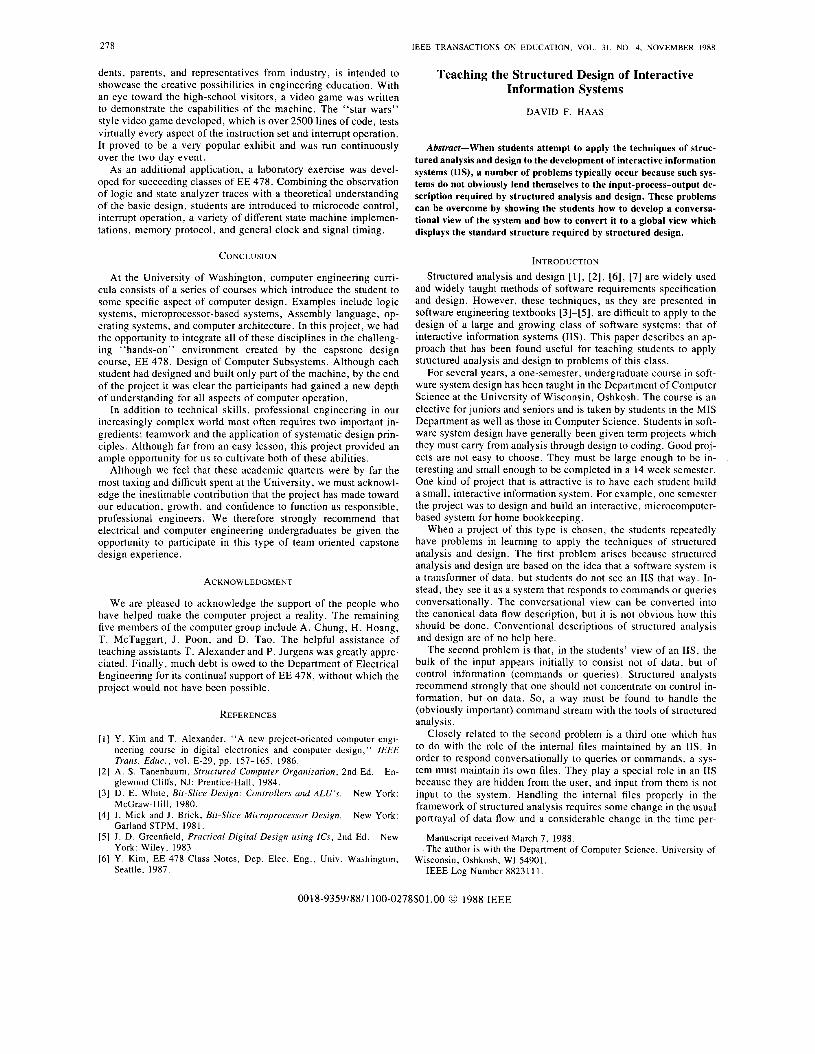
A BRIEF EXAMPLE In Fig. 8, the reader may find a data flow diagram of the con-
versational view of a system that allows an investor to keep track of investments in mutual funds. The system shown in Fig. 8 is highly simplified and allows the user to do only three things. He can record transactions (sales, purchases, or reinvestment of earn- ings); he can obtain a list of his holdings; and he can obtain a
IEEE TRANSACTIONS ON EDUCATION, VOL. 31, NO. 4. NOVEMBER 1988 283
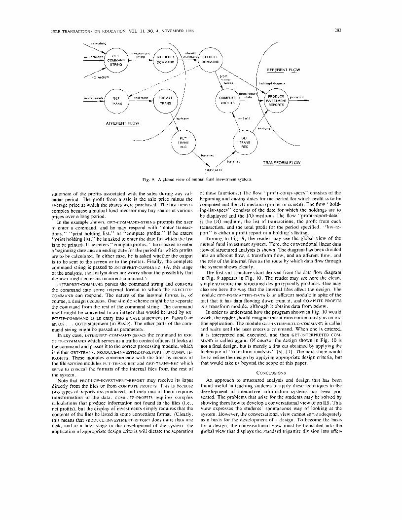
Fig. 9. A global view of mutual fund investment system
statement of the profits associated with the sales during any cal- endar period. The profit from a sale is the sale price minus the average price at which the shares were purchased. The last item is complex because a mutual fund investor may buy shares at various prices over a long period.
In the example shown, GET-COMMAND-STRING prompts the user to enter a command, and he may respond with “enter transac- tions,’’ “print holding list,” or “compute profits.” If he enters “print holding list,” he is asked to enter the date for which the list is to be printed. If he enters “compute profits,” he is asked to enter a beginning date and an ending date for the period for which profits are to be calculated. In either case, he is asked whether the output is to be sent to the screen or to the printer. Finally, the complete command string is passed to INTERPRET-COMMAND. (At this stage of the analysis, the analyst does not worry about the possibility that the user might enter an incorrect command.)
INTERPRET-COMMAND parses the command string and converts the command into some internal format to which the EXECUTE- COMMAND can respond. The nature of the internal format is, of course, a design decision. One simple scheme might be to separate the command from the rest of the command string. The command itself might be converted to an integer that would be used by EX- ECUTE-COMMAND as an entry into a CASE statement (in Pascal) or an ON . . . GOTO statement (in Basic). The other parts of the com- mand string might be passed as parameters.
In any case, INTERPRET-COMMAND passes the command to EXE- CUTE-COMMAND which serves as a traffic control officer. It looks at the command and passes it to the correct processing module, which is either GET-TRANS, PRODUCE-INVESTMENT-REPORT, or COMPUTE- PROFITS. These modules communicate with the files by means of the file service modules PUT-TRANS-REC and GET-TRANS-REC which serve to conceal the formats of the internal files from the rest of the system.
Note that PRODUCE-INVESTMENT-REPORT may receive its input directly from the files or from COMPUTE-PROFITS. This is because two types of reports are produced, but only one of them requires transformation of the data. COMPUTE-PROFITS requires complex calculations that produce information not found in the files (i.e., net profits), but the display of investments simply requires that the contents of the files be listed in some convenient format. (Clearly, this means that PRODUCE-INVESTMENT-REPORT does more than one task, and at a later stage in the development of the system, the application of appropriate design criteria will dictate the separation
of these functions.) The flow “profit-comp-specs” consists of the beginning and ending dates for the period for which profit is to be computed and the I/O medium (printer or screen). The flow “hold- ing-list-specs’’ consists of the date for which the holdings are to be displayed and the I/O medium. The flow “profit-report-data’’ is the I/O medium, the list of transactions, the profit from each transaction, and the total profit for the period specified. “Inv-re- port” is either a profit report or a holding’s listing.
Turning to Fig. 9, the reader may see the global view of the mutual fund investment system. Here, the conventional linear data flow of structured analysis is shown. The diagram has been divided into an afferent flow, a transform flow, and an efferent flow, and the role of the internal files as the route by which data flow through the system shows clearly.
The first-cut structure chart derived from the data flow diagram in Fig. 9 appears in Fig. 10. The reader may see here the clean, simple structure that structured design typically produces. One may also see here the way that the internal files affect the design. The module GET-FORMATTED-DATA is an afferent module in spite of the fact that it has data flowing down from it, and COMPUTE-PROFITS is a transform module, although it obtains data from below.
In order to understand how the program shown in Fig. I O would work, the reader should imagine that it runs continuously as an on- line application. The module GET-INTERPRETED-COMMAND is called and waits until the user enters a command. When one is entered, it is interpreted and executed, and then GET-INTERPRETED-COM- MAND is called again. Of course, the design shown in Fig. 10 is not a final design, but is merely a first cut obtained by applying the technique of “transform analysis” [3], [7]. The next stage would be to refine the design by applying appropriate design criteria, but that would take us beyond the scope of this paper.
CONCLUSIONS An approach to structured analysis and design that has been
found useful in teaching students to apply these techniques to the development of interactive information systems has been pre- sented. The problems that arise for the students may be solved by showing them how to develop a conversational view of an 11s. This view expresses the students’ spontaneous way of looking at the system. However, the conversational view cannot serve adequately as a basis for the development of a design. To become the basis for a design, the conversational view must be translated into the global view that displays the standard tripartite division into affer-
284 IEEE TRANSACTIONS ON EDUCATION, VOL. 31. NO. 4. NOVEMBER 1988
- c o m m a ~ ~ b / c o m m ~ ~ d -5tmg -string $:%:‘and -trizif -
GET-COMMAND INTERPRET GET -STRING C O M M A N D -TRANS
Inv-trans-data
trans-rec
-command
GET-DATE
TRANS-FILE
Fig. IO. First-cut structure chart for the mutual fund investment system.
.report
ent, transform, and efferent flows. This may then be used as a basis for design using the usual tools of structured design.
cording to Corti, the output of the MOSFET transmission gate shown in Fig. 1 can be expressed, approximately, by
REFERENCES
[l) T. Demarco, Structured Analysis and System Specijication. New
[2] G. J . Myers, “Characteristics of composite design,” Datamation,
[3] M. Page-Jones, The Practical Guide to Structured Systems Design.
[4] R. S . Pressman, Sojiware Engineering: A Practitioner’s Approach.
[SI I. Sommerville, Soffware Engineering. London: Addison-Wesley,
[6] W. P. Stevens, G . J . Meyers, and L. L. Constantine, “Structured
[7] E. Yourdon and L. L. Constantine, Structured Design: Fundamentals Engle-
York: Yourdon, 1978.
vol. 19, pp. 100-102.
New York: Yourdon, 1980.
New York: McGraw-Hill, 1987.
1982.
design,”IBMSyst. J . , vol. 13, pp. 115-139, 1974.
of a Discipline of Computer Program and Systems Design. wood Cliffs, NJ: Prentice-Hall, 1975.
On the Prediction of Transmission Errors of MOSFET Switches
MUHAMMAD TAHER ABUELMA’ATTI
where
and
r0 K , = - RL
e
VTH - VG x = -
x: e : the input voltage eo: the output voltage VTH: the threshold voltage VG: the gate voltage ro:
is zero R L : the load resistance.
is always positive and less than one [2]
the on resistance of the MOSFET when the input voltage
Equation (1) is nonlinear, even when E is a linear function of x. Hence, the output will not be a true replica of the input voltage. Equation ( 2 ) in its present form, however, will not allow closed- form expressions for the output product levels resulting from the transmission of a multisinusoidal signal at the input o f t h e MOS- FET switch. Consequently, Corti approximated ( 2 ) by the infinite series
Abstract-A simple formula is presented for the impedance error of a MOSFET-resistor transmission gate. Using this formula, closed-form expressions are derived for the output products resulting from switch- ing sinusoidal input signals. CD
E = K , k = O ( - l ) I x k + ’ . (3)
For obvious reasons, Corti truncated (3) after the fourth-order term and thence obtained expressions for the loss in the transmitted sig- nal, dc offset, and harmonic distortion products in the output. This approximation is, however, valid only for small-signal input volt- ages wi thx < 0.5.
The purpose Of this paper is, therefore, to present an a h n a t i v e formula for approximating ( 2 ) . The formula Permits c l o s e d - f o ~ expressions for the output distortion, output dc offset, and loss in the transmitted signal over a wider range of input signal levels.
I. INTRODUCTION Recently, Corti [ l ] investigated the errors in the transmission of
ac signals caused by the on resistance of a MOSFET switch. Ac-
Manuscript received November 19, 1988. The author is with the Department of Electrical Engineering and Corn-
puter Science, College of Engineering, University of Bahrain, Isa Town, Bahrain.