Engineering Policy Subcommittee: Approved 10/09/03 Rev 03-1092B Engineering Policy Committee: Approved 10/23/03 Submitted by Traffic Director’s of Operations & Project Dev.: Approved 10/30/03 Team Leader: Julie Stotlemeyer Chief Engineer: 12/03/03 10/09/03 Team Members and Resources Julie Stotlemeyer-tr Kirsten Munck- de (Rationale: This section was created for the equipment and material requirements that were moved from Sec 902.) 10/09/03 - Revised 1092.1, 1092.4.2.4 and 1092.4.7.7.2. Moved language in 1092.2.4.1, 1092.4.5.2, 1092.4.7.7 and 1092.6 to Sec 902. 10/23/03 – EPC questioned whether the contracting industry (Meyers Electric, Gershner, etc.) had the opportunity to comment, but approved as revised. SECTION 109 2 0 SIGNAL E QUIPMENT 109 2 0 .1 Signal Heads . Signal heads shall meet the following requirements: (a) All signal heads shall be weatherproof and black in color in accordance with Sec 109 2 0 .1.1 . All indications shall be 12 inches (300 mm) unless otherwise specified. (b) All signal indications in conventional signal heads shall be illuminated with light emitting diode (LED) modules. LED modules , excluding circular yellow and arrow indications, shall be in accordance with ITE specifications and standards for LED vehicle traffic signal modules, excluding circular yellow and arrow indications, and shall be in accordance with the following: (1) The lens of each red indication shall be tinted with a wavelength-matched color to reduce sun phantom effect and enhance on/off contrast. The tinting shall be uniform across the lens face. If a polymeric lens is supplied, a surface coating shall be applied to provide abrasion resistance.
Transcript
Engineering Policy Subcommittee: Approved 10/09/03 Rev 03-1092BEngineering Policy Committee: Approved 10/23/03 Submitted by TrafficDirector’s of Operations & Project Dev.: Approved 10/30/03 Team Leader: Julie StotlemeyerChief Engineer: 12/03/03 10/09/03
Team Members and ResourcesJulie Stotlemeyer-tr Kirsten Munck-de
(Rationale: This section was created for the equipment and material requirements that were moved from Sec 902.)
10/09/03 - Revised 1092.1, 1092.4.2.4 and 1092.4.7.7.2. Moved language in 1092.2.4.1, 1092.4.5.2, 1092.4.7.7 and 1092.6 to Sec 902.
10/23/03 – EPC questioned whether the contracting industry (Meyers Electric, Gershner, etc.) had the opportunity to comment, but approved as revised.
SECTION 10920
SIGNAL EQUIPMENT
10920.1 Signal Heads. Signal heads shall meet the following requirements:
(a) All signal heads shall be weatherproof and black in color in accordance with Sec 10920.1.1. All indications shall be 12 inches (300 mm) unless otherwise specified.
(b) All signal indications in conventional signal heads shall be illuminated with light emitting diode (LED) modules. LED modules, excluding circular yellow and arrow indications, shall be in accordance with ITE specifications and standards for LED vehicle traffic signal modules, excluding circular yellow and arrow indications, and shall be in accordance with the following:
(1) The lens of each red indication shall be tinted with a wavelength-matched color to reduce sun phantom effect and enhance on/off contrast. The tinting shall be uniform across the lens face. If a polymeric lens is supplied, a surface coating shall be applied to provide abrasion resistance.
(2) LED modules shall not contain Aluminum Gallium Arsenide (AlGaAs) LEDs.
(3) LED modules shall provide constant light output under power. Modules with dimming capabilities shall have the option disabled or set on a non-dimming operation.
(4) In the event of a power outage, light output from the LED modules shall cease instantaneously.
(5) Modules shall be designed to sense a loss of light output due to catastrophic LED failures between 25 and 40 percent. Loss of light output due to LED failure shall not be detected for losses less than 25 percent, but shall be detected for any loss of light greater than 40 percent. The unit, upon sensing a valid loss of light, shall present an impedance of 500 kilo ohms to the alternating current line.
Engineering Policy Subcommittee: Approved 10/09/03 Rev 03-1092BEngineering Policy Committee: Approved 10/23/03 Submitted by TrafficDirector’s of Operations & Project Dev.: Approved 10/30/03 Team Leader: Julie StotlemeyerChief Engineer: 12/03/03 10/09/03
(c) Yellow circular LED modules shall meet or exceed the minimum initial luminous intensity and minimum maintained intensity values as shown below throughout the useful life based on normal use in a traffic signal operation at 77 F (25 C). LED modules shall be tested in accordance with California Test No. 604 and Caltrans approved.
(d) Yellow and green arrow LED modules shall meet or exceed the minimum initial luminous intensity and minimum maintained intensity values as shown below throughout the useful life based on normal use in a traffic signal operation at 77 F (25 C). LED modules shall be tested in accordance with California Test 3001 and Caltrans approved.
Minimum Initial Intensity (candela/m2 )Yellow Green
Arrow Indication 11,000 11,000
Minimum Maintained Intensity (candela/m2 )Yellow Green
Arrow Indication 11,000 11,000 (e) Incandescent and optically limiting traffic signal lamps shall be in accordance with the Institute of Transportation Engineers Standard for Traffic Signal Lamps and the following specifications. Lamps shall be incandescent or optically limiting traffic signal lamps, as specified on the plans, and compatible with the design requirements of the optical systems of standard traffic signals. The construction features of the traffic signal lamps require that the filament shall be adequately supported to withstand the vibration induced from traffic and wind when burning in a horizontal position. Incandescent bulbs for signal indications, conventional, optically limiting and pedestrian signal heads, shall be certified by the manufacturer.
(1) The glass envelope of the lamps shall be legibly and permanently marked to show the manufacturer's insignia or trademark, design voltage and rated lumens or wattage. Lamps shall meet the following requirements:
Engineering Policy Subcommittee: Approved 10/09/03 Rev 03-1092BEngineering Policy Committee: Approved 10/23/03 Submitted by TrafficDirector’s of Operations & Project Dev.: Approved 10/30/03 Team Leader: Julie StotlemeyerChief Engineer: 12/03/03 10/09/03
Light Center Length, inches 2-7/16 3 ----Position of Burning Horizontal Horizontal HorizontalWatts 116 135 150Rated Voltage 130 120 - 125 115Rated Initial Lumens,Minimum @ Rated Voltage
1260 1750 N/A
Rated Beam Candlepower, candelas
N/A N/A 950
Rated Average Life, Hours @ Rated Voltage
6000 6000 6000
(2) The glass envelope of the lamps shall be legibly and permanently marked to show the manufacturer's insignia or trademark, design voltage and rated lumens or wattage.
10920.1.1 Housing, Door and Visor. All new signal sections shall be clean, smooth and free from imperfections. The connection between signal housings shall be weatherproof. Housings shall be rigidly fastened together by a three- or four- bolt assembly or other connectors approved by the engineer. Doors which will exclude dust and moisture shall be used to ensure a weatherproof unit. A tunnel visor shall be supplied with each signal section, and each door shall have provisions for attachment of the tunnel visor. All visors shall be held in place by four stainless steel fastening screws or bolts and shall be capable of being removed without opening the signal head door. Internal bosses or inserts shall be provided in each housing for mounting a terminal block and attachment of back plates. The top and bottom exterior of the housing shall be flat to ensure perfect alignment of assembled sections. The housing of each section shall be one piece with sides, back, top and bottom integrally molded. The design of the housing shall be such
Engineering Policy Subcommittee: Approved 10/09/03 Rev 03-1092BEngineering Policy Committee: Approved 10/23/03 Submitted by TrafficDirector’s of Operations & Project Dev.: Approved 10/30/03 Team Leader: Julie StotlemeyerChief Engineer: 12/03/03 10/09/03
that, with the aid of simple tools and the addition of standard parts, it shall be possible to make any assembly consisting of one or more signal sections and, with the addition of standard bracket assemblies, assemble signal faces into multi-way traffic signal head configurations.
(a) Aluminum Housing. Each housing shall be die cast aluminum.
(b) Polycarbonate Housing. All material used in construction of this type of signal head shall be of ultraviolet stabilized color-impregnated polycarbonate resin. The housing shall have a minimum thickness of 0.09 inch (2.2 mm) and shall be ribbed or plated to produce added strength. If signal housings are not ribbed, minimum 0.10-inch (2.5 mm) aluminum plates shall be furnished and installed inside and outside the section housing at all points of attachment of the pipe bracket.
10920.1.2 Traffic Signal Lenses. All lenses shall be glass. Signal lens nominal diameter shall be as specified. Arrow lenses shall be of the size, color and design specified., and Ddull or dark gray enamel shall be baked or fired into the convex surface of the lens such that only the arrow indication will be illuminated. The enamel shall be hard, durable and not peel or flake. The enamel shall totally hide the light from a 200-watt lamp. The lens and reflector, in conjunction with a molded gasket and lamp receptacle, shall form a sealed unit. All lenses shall be secured with screws and tabs. Compression mounting shall not be used.
10920.1.3 Reflectors. All reflectors shall be aluminum and furnished with a non-corrosive holder mounted either in the housing or on the door.
10920.1.4 Electrical. The receptacle shall be designed to hold a Type A-19 or A-21, medium base, traffic signal lamp. Rotation of the receptacle for positioning the lamp filament shall be possible without using tools. The terminal wire shall not be spliced. If single signal sections are specified, each section shall be furnished with a terminal block. All terminal blocks shall be rigidly secured to the section housing. A minimum of four terminals shall be provided for each terminal block. A lamp receptacle retainer shall be provided which can be installed or removed without the use of tools. Retaining rings designed to encompass and be embedded into the receptacle exterior surface shall not be used.
10920.1.5 Louvers. Louvers shall be marked as to degree of cut-off. The degree of cut-off shall be stamped on the louver or printed on a decal on the front of the louver and be visible after installation.
10920.1.5.1 Fixed louvers shall be formed of 0.025-inch (0.6 mm) sheet aluminum. The top and bottom bends of each fin shall be securely fastened to the inside of the supporting ring. The angles of cut-off from either side of the center axis of the light beam shall be provided by six types of louvers: Type A - 3 degrees, Type B - 7 degrees, Type C - 10 1/2 degrees, Type D - 14 degrees, Type E - 18 1/2 degrees and Type F - 26 1/2 degrees.
10920.1.5.2 Adjustable louver units shall be composed of an acrylonitrile butadiene styrene (ABS) plastic housing and polycarbonate baffles. The unit shall be designed to prevent light leakage between the housing and the visor. The unit shall have an adjustable view range of 7 to 42 degrees. All plastic materials shall be ultraviolet stabilized. All hardware shall be brass or stainless steel.
Engineering Policy Subcommittee: Approved 10/09/03 Rev 03-1092BEngineering Policy Committee: Approved 10/23/03 Submitted by TrafficDirector’s of Operations & Project Dev.: Approved 10/30/03 Team Leader: Julie StotlemeyerChief Engineer: 12/03/03 10/09/03
10920.1.6 Hardware. Hardware shall be 1 1/2-inch (38 mm) galvanized steel or unfinished aluminum, except aluminum pipe brackets and side mount brackets. Aluminum pipe brackets shall have a spun finish. Side mount brackets may be constructed of molded, glass-impregnated polycarbonate no greater than 12 inches (300 mm) in length. Elbows, tees and crosses shall be straight threaded and furnished with a square head set screw at each connection point to ensure rigid mounting. Fittings attached to the signal housing shall incorporate serrations or, by the use of an adapter ring, be compatible with the serrations on the signal housing.
10920.1.7 Backplates. Backplates, as shown on the plans, shall be provided on all signal heads as shown on the plans. The bBackplates shall be black in color and constructed of flat pre-cut or preformed thermoplastic. Flat pre-cut thermoplastic backplates shall have a minimum thickness of 0.250 inches (6 mm). Preformed thermoplastic backplates shall have rolled out edges and a minimum final thickness of 0.1 inches (2.5 mm).
10920.1.8 Optically Limiting Signal Heads. All signal sections shall meet the following requirements:
(a) Each signal housing shall be die cast aluminum having a chromate preparatory treatment. The signal housing and lens holder shall be predrilled for backplates and visors. All access openings shall be sealed with weather resistant gaskets. Hinge and latch pins shall be non-ferrous metal or stainless steel. The lens holder and interior of the housing shall be optical black. The housing shall mount to standard 1 1/2-inch (38 mm) fittings as a single section, as a multiple section face or in combination with conventional signals. The signal housing shall be provided with an adjustable connection that permits incremental tilting from zero to 10 degrees above or below the horizontal while maintaining a common vertical axis through the mounting assembly. Housing connection shall permit external adjustment about the mounting axis in 5-degree increments. Attachments such as visors, backplates or adapters shall readily fasten to mounting surfaces without affecting weatherproof characteristics and light integrity of the signal.
(b) The optical system shall consist of an objective lens, optical limiter-diffuser, lamp, lamp fixture and optical masking tape.
(1) The objective lens shall be a high-resolution planar incremental lens, hermetically sealed within a flat laminant of weather-resistant acrylic or approved equivalent. The lens shall be symmetrical in outline and if rotated to any 90-degree orientation about the optical axis, shall not displace the primary image.
(2) The optical limiter-diffuser shall provide an accessible imaging surface at focus on the optical axis for objects up to 1200 feet (365 m) distant and permit an effective veiling mask to be applied as determined by the desired visibility zone. The optical limiter-diffuser shall be provided with positive positioning and composed of heat resistant glass.
(3) The lamp shall be in accordance with Sec 10920.1(e) and shall have an integral reflector. The lamp shall be attached to the diffusing element with a collar having a specular inner surface.
(4) The lamp fixture shall consist of a separately accessible housing and integral lamp support, an adjustable ceramic socket and a self-aligning, quick release lamp
Engineering Policy Subcommittee: Approved 10/09/03 Rev 03-1092BEngineering Policy Committee: Approved 10/23/03 Submitted by TrafficDirector’s of Operations & Project Dev.: Approved 10/30/03 Team Leader: Julie StotlemeyerChief Engineer: 12/03/03 10/09/03
retainer. Electrical connection between section housing and lamp housing shall be accomplished with an interlock assembly which disconnects the lamp holder when the door is opened.
(5) A signal lamp intensity control shall be supplied in each signal section to provide dimming of the signal lamp as the ambient light intensity drops below approximately 3 footcandles (32 lux).
10920.1.9 Pedestrian Signal Heads. Pedestrian signal heads shall be in accordance with ITE specifications and standards for pedestrian traffic control signal indications and the following:
(a) Pedestrian signal head housings shall be constructed as shown on the plans of a one-piece, 0.250-inch (6 mm) thick, polycarbonate material. The housing shall include an integral mounting bracket designed for side-of-pole mounting on all makes of signal poles with a terminal compartment and minimum 5-position, double-row terminal block.
(b) The door, lens and any openings in the housing shall have gaskets or seals to exclude dust and moisture from the inside of the compartment.
(c) Lenses shall be constructed of polycarbonate material.
(d) Pedestrian signal head units shall be provided with a manufactured, preformed rectangular visor or screen-type louver.
(e) All plastic materials shall be ultraviolet stabilized.
(f) Indications shall be ITE Class 3 symbol messages. The "UPRAISED HAND" symbol shall be illuminated with a filled, Portland orange LED module. The "WALKING PERSON" symbol shall be illuminated with a filled, white LED module. The LED module shall be in accordance with applicable portions of Sec 10920.1(b).
(g) Pedestrian traffic control signal faces shall be constructed such that both messages are displayed from the same message-bearing surface. The "WALKING PERSON" symbol shall be located to the right of the "UPRAISED HAND" symbol.
10920.1.10 Painting and Finishing. All aluminum signal head parts, including the housing, housing door, visors, louvers and backplates, except the mounting brackets and other hardware, shall be primed and painted flat black in their entirety. All polycarbonate signal head parts, including the housing, housing door, visors and backplates shall be constructed from ultraviolet stabilized black-impregnated polycarbon resin. The mounting brackets and hardware, except the aluminum pipe brackets and polycarbonate side mounted brackets, shall be galvanized steel or unfinished aluminum. Aluminum pipe brackets shall have a spun finish. Painting of the mounting brackets and hardware will not be permitted.
10920.2 Posts and Mast Arms. A grounding lug shall be provided for all units. A grounding conductor shall provide grounding continuity for all metallic, noncurrent carrying poles in one circuit.
Engineering Policy Subcommittee: Approved 10/09/03 Rev 03-1092BEngineering Policy Committee: Approved 10/23/03 Submitted by TrafficDirector’s of Operations & Project Dev.: Approved 10/30/03 Team Leader: Julie StotlemeyerChief Engineer: 12/03/03 10/09/03
10920.2.1 Steel Pedestal Posts. Steel pedestal posts shall be 4 1/2-inch (114 mm) outside diameter schedule 40 steel pipe. The base shall be cast iron, free from imperfections and provided with a suitable plastic, fiberglass or cast door for wiring access. The grounding lug shall be inside the base. The bolt circle and hole diameter shall be as shown on the plans. After fabrication, posts and bases shall be fully galvanized.
10920.2.2 Aluminum Pedestal Posts. Aluminum pedestal posts shall be schedule 80 straight tubing of 6063-T6 aluminum alloy in accordance with ASTM B 210, with a 4 1/2-inch (114 mm) outside diameter. The pedestal base casting shall be either permanent mold casting of Alloy 356.0 F, in accordance with ASTM B 108 or sand castings of Alloy 356.0 F, in accordance with ASTM B 26. The base shall be free from imperfections and provided with a suitable door for wiring access. The base and post shall be joined by threaded connection. Welded connections will not be allowed. The grounding lug shall be provided inside the base. All hardware shall be non-ferrous metal or stainless steel.
10920.2.3 Signal Post and Mast Arm Pre-Approval. Fabricators shall submit six copies of shop drawings and supporting calculations to Traffic. Submittals shall be approved by Traffic in writing prior to fabrication of the signal posts and mast arms. Shop drawings shall indicate complete design details required for post and mast arm fabrication, including material grades and thicknesses, welding and orientation of any longitudinal seams. The projected areas and weights (masses) of signs and signals used in the design of the post and mast arms shall be shown on the shop drawings. Design details for all possible post and mast arm combinations as shown on the plans may be submitted. Shop drawings shall provide post and mast arm installation and hardware details. All welding procedures shall be prepared by the manufacturer as a written procedure specification and shall be submitted with the shop drawings for approval. Approval of the weld procedures will be required before approval of the shop drawings. Shop drawings shall indicate the specific approved welding procedure to be used for each joint. Shop drawings and supporting stress calculations shall be signed and sealed by a registered professional engineer in the State of Missouri. Manufacturers shall submit all required documentation, in accordance with Sec 10920.2.4.3. Upon written approval, pre-approved drawings may be used on any project where the design conditions of the shop drawings are not exceeded.
10920.2.4 Steel Posts and Mast Arms. Steel posts and mast arms shall be continuously tapered, hollow shafts fabricated as one continuous shaft or as individual segments, not less than 10 feet (3 m) in lengthlong, joined together using electrically welded, intermediate, transverse, full penetration, circumferential joints. Steel posts and mast arms shall be fabricated from basic oxygen or open hearth steel sheet. The continuous, tapered, hollow shafts or individual segments shall be manufactured from one or two lengths of steel sheet, with one or two continuous, welded, longitudinal seams. The longitudinal seams in the mast arm shall be located outside of the upper half of the cross section of the member. Where transverse, full penetration, circumferential welds are used, the fabricator shall furnish to the engineer written certification that 100 percent of all such welds have been radiographed or ultrasonic tested by an independent testing agency using a qualified non-destructive testing technician, as described in Section 6.14.7 of ANSI/AWS D1.1 Structural Welding Code-Steel, and equipment calibrated annually. The testing agency shall be approved by the engineer prior to fabrication. Post base and mast arm attachment plates shall be plate steel attached to the larger end of the shafts by continuous welds on the inside and outside of the shaft. After manufacture, the material shall have a minimum yield strength of 48,000 pounds per square inch (330 MPa).
Engineering Policy Subcommittee: Approved 10/09/03 Rev 03-1092BEngineering Policy Committee: Approved 10/23/03 Submitted by TrafficDirector’s of Operations & Project Dev.: Approved 10/30/03 Team Leader: Julie StotlemeyerChief Engineer: 12/03/03 10/09/03
10920.2.4.1 A handhole equipped with a suitable metal cover shall be provided in the post near the base and 12 inches (300 mm) above the mast arm connection if luminaire mounting is specified. A grounding lug or connector shall be provided inside the post near the handhole. A removable raintight metal pole cap shall be provided on the top of the post and on the small end of each mast arm. All handhole covers and metal caps shall be securely attached to the post or arm with a galvanized steel chain and held in place by screws. The chain shall be attached to the inside of the post or arm and shall be of sufficient length to allow maintenance access. An identification tag shall be provided with all posts and mast arms as shown on the plans. The tag shall be aluminum or stainless steel with embossed or engraved letters and numbers. The post tag shall be attached to the pole 6 inches (150 mm) above the top of the handhole. The mast arm tag shall be attached 3 inches (75 mm) from the base of the end cap. The base plate shall be equipped with four cast steel or cast iron nut covers in accordance with AASHTO M 103 or M 105 or four aluminum nut covers and shall have four galvanized or stainless steel screws for securing covers to the pole. All poles, shoe bases, base plates and cast steel or cast iron nut covers shall be fully galvanized after fabrication. All anchor bolt nuts shall be completely covered by nut covers. Luminaire bracket arms, when specified, shall be included with the post and mast arm, and no direct payment will be made. The contractor has the optionmay to furnish posts with shape, gage and dimensions meeting or exceeding those required by the plans and specifications, provided shop drawings are submitted and approved in accordance with Sec 10920.2.3.
10920.2.4.2 Welding and fabrication of the assemblies shall be in accordance with the ANSI/AWS D1.1 Structural Welding Code-Steel. All requirements of the welding code for tubular structures shall apply to the fabrication for the post and mast arm shafts and shall include any welds used to attach these members to plates or other hardware. The manufacturer shall employ qualified personnel to perform all visual and nondestructive testing (NDT) required. In addition to the visual inspections and NDT that may otherwise be required by the welding code, the manufacturer shall perform 100 percent magnetic particle (MT) testing of circumferential fillet welds used to attach the flange plate to the larger end of the mast arm shaft. NDT personnel shall be qualified as set forth in paragraph 6.14.7 of ANSI/AWS D1.1 Structural Welding Code-Steel. Qualifications of NDT personnel shall be submitted to the engineer for approval.
10920.2.4.3 The post and mast arm manufacturer shall be certified under the AISC certification program, Conventional Steel Building or higher category. Evidence of current AISC certification will be required prior to the approval of shop drawings, and lapsing of the certification will be cause for the manufacturer's removal from the approved list of suppliers.
10920.2.4.4 Steel posts, luminaire bracket arms, mast arms, nut covers and plate steel bases shall be hot-dip galvanized inside and out after fabrication, visual inspections and NDT testing. Galvanized material shall be handled in a manner to avoid damage to the surface. Any galvanized material on which the coating has been damaged will be rejected or may, with the approval offrom the engineer, be repaired in accordance with Sec 712.
10920.2.5 Fabricator's Certification. Prior to erection of the posts and mast arms, the contractor shall furnish to the engineer a fabricator's certification in triplicate. The certification willshall specifically state the fabricated posts and mast arms have been quality control inspected by the fabricator and all material and manufacturing processes used were in full compliance with the specification requirements and the approved shop drawings and weld procedures. The certification shall be accompanied by supporting documentation, which shall includinge the
Engineering Policy Subcommittee: Approved 10/09/03 Rev 03-1092BEngineering Policy Committee: Approved 10/23/03 Submitted by TrafficDirector’s of Operations & Project Dev.: Approved 10/30/03 Team Leader: Julie StotlemeyerChief Engineer: 12/03/03 10/09/03
results of the visual inspections and NDT in accordance with Sec 10920.2.4.2 and copies of the pre-approved drawings required by Sec 10920.2.3.
10920.3 Lighting Control Cabinet. The lighting control cabinet shall contain a control panel constructed of the same material as the cabinet. Circuit breakers, the photoelectric switch, a contactor, if specified, and any other specified equipment for luminaire control shall be installed on the panel. Control cabinets shall be of sufficient size to house all equipment as shown on the plans. Cabinets shall be dust tight, watertight, NEMA 4 and constructed of aluminum or stainless steel. All hinges, catches and other hardware shall be stainless steel. Cabinets shall have a No. 2 Corbin cabinet lock. Photoelectric switches and contactors shall be in accordance with Sec 901. Circuit breakers shall be Type B circuit breakers in accordance with Sec 901.
10920.4 Traffic Controller Assemblies. Traffic controller assemblies will be defined as the complete assembly of all required equipment and components for control of traffic signal indications. The type of controller assembly required for each location shall be as specified in the contract documents.
10920.4.1 NEMA TS1. Each controller assembly shall consist of a controller cabinet, signal controller, back panel, conflict monitor, card rack assembly, all required wiring, switches and connectors and all other equipment as defined in these specifications and as shown on the plans. Double controller assemblies to control two intersections shall consist of a controller cabinet, two signal controllers, two back panels, two conflict monitors, two card rack assemblies, all required wiring, switches and connectors and all other equipment as defined in these specifications and as shown on the plans.
(a) Each controller and associated equipment shall be designed to operate on 120 volts, 60 hertz, single phase, alternating current.
(b) Variations in the voltage of the power supply of plus or minus 10 percent or sustained temperatures inside the cabinet between -20 F (-28 C) and 165 F (74 C) shall not change the total time cycle of pretimed controllers or the length of any interval, portion, period or unit extension of actuated controllers by more than 5 percent or cause electrical or mechanical damage. Heater elements shall not be used to attain compliance with these requirements.
(c) Vibration shall not affect normal operation of any equipment.
(d) All controllers and other specified auxiliary equipment shall be properly protected with fuses on each applicable unit. Fuses shall be installed in 1/4-twist or screw-in type fuse holders. Pop-out fuse holders shall not be used.
10920.4.1.1 Controller Cabinets. Controller cabinets shall be cast aluminum or 0.125 inch (3 mm) reinforced sheet aluminum alloy and shall be of clean-cut design and appearance. The cabinet shall provide ample space for housing all equipment and components. Controller cabinets housing solid-state controllers shall be furnished with unused cabinet space measuring 18 inches (450 mm) wide by 12 inches (300 mm) high by 12 inches (300 mm) deep unless coordination equipment is specified on the plans. For pretimed and actuated NEMA controllers, the cabinet shall support a sixteen-position backpanel. Double controller cabinets for two controllers shall support two sixteen-position back panels. All double cabinets shall have two doors that are hinged on the outside corners of the cabinet such that the doors open away from each other.
Engineering Policy Subcommittee: Approved 10/09/03 Rev 03-1092BEngineering Policy Committee: Approved 10/23/03 Submitted by TrafficDirector’s of Operations & Project Dev.: Approved 10/30/03 Team Leader: Julie StotlemeyerChief Engineer: 12/03/03 10/09/03
Double cabinets shall have a divider between the two halves of the cabinet with an 8-inch (200 mm) opening between the compartments at the bottom of the divider for wiring between the compartments. The cabinet shall contain a rigid mounting table, sliding ways or hinged support of such construction that the controller and auxiliary equipment may be withdrawn from the cabinet without breaking any electrical connections or interrupting normal controller operation. Hinged supports shall be welded to the controller cabinet. Electrical connectors on the controller and auxiliary equipment to all circuits shall be NEMA 1/4 twist or MS type. Components of controller cabinets shall meet the following requirements.
(a) A hinged door or doors shall provide complete access to the interior of the cabinet. Door holds shall secure the door in an open position at least 90 degrees from the closed position and shall be furnished with each cabinet. The doors shall fit against a raintight gasket. Each door shall have a stamped or raised outside designation, "Traffic Control" or other approved identification. Each main cabinet door shall have a No. 2 Corbin cabinet lock and provisions for locking with a padlock. The handles for each door shall swing outward. An auxiliary door, positioned on each main cabinet door, equipped with a raintight gasket, shall allow access to a police panel and shall be equipped with a lock whose key will not unlock the main door. Two keys shall be furnished for each type lock used. The door hinges and pins shall be of corrosion-resistant metal. Pins shall be rolled or solid rod, at least 1/8 inch (3 mm) in diameter, except if continuous hinges are furnished, the pins shall be continuous the full length of the hinges and shall be not less than 1/16 inch (1.5 mm) in diameter.
(b) The back panel in all controller cabinets shall be hinged at the bottom to permit the top of the panel to be rotated forward and down to an angle of not less than 45 degrees with all components, including load switches, attached for maintenance purposes. The bottom of the back panel shall be no less than 6 inches (150 mm) above the bottom of the cabinet.
(c) Cabinets housing solid-state controllers shall have a thermostatically controlled ventilating fan with exhausting capability in an enclosure of at least 150 cubic feet per minute (0.07 m3 /s) for cabinets up to 30.5 cubic feet (0.9 m3 ) and at least 250 cubic feet per minute (0.12 m3 /s) for cabinets 30.5 cubic feet (0.9 m3 ) and more, installed in the top of the cabinet. These cabinets shall be supplied with a replaceable furnace-type fiberglass filter of at least one square foot (0.06 m2 ) area mounted behind louvers in the lower one-fourth of the door.
(d) Each controller cabinet shall be furnished with a clearly labeled switch mounted in the access or police panel to place the signals on flash. Operation of this switch shall not affect the electrical power supply to the controller. This shall be the only control switch accessible from the police panel.
(e) Each cabinet shall be provided with a grounded service outlet and a switch-controlled lamp receptacle.
(f) Each cabinet shall contain a separate aluminum power panel containing the following equipment.
(1) OneTwo Type B circuit breakers in accordance with Sec 901. TheOne breaker shall interrupt power to the controller and signals. The frame size and trip rating iswill be shown on the traffic signal plans or designated in the contract. The second
Engineering Policy Subcommittee: Approved 10/09/03 Rev 03-1092BEngineering Policy Committee: Approved 10/23/03 Submitted by TrafficDirector’s of Operations & Project Dev.: Approved 10/30/03 Team Leader: Julie StotlemeyerChief Engineer: 12/03/03 10/09/03
(2) One Type B circuit breaker in accordance with Sec 901. The breaker shall be an auxiliary breaker which interrupts power to the cabinet lamp and receptacle. The frame size and trip rating shall be 15 amperes.
(32) One mercury contactor controlling power to the signal bus.
(43) One radio frequency line filter.
(54) One line surge protector.
(65) One terminal block for alternating current power input.
(76) One ground bus terminal block.
(87) One isolated neutral bus terminal block.
(g) If specified, a manual operation push button shall be installed in the police panel. The push button shall be wired for manual operation of the signals. The push button shall be water-resistant and designed to protect the user against electrical shock and shall be supplied with a coiled cord with a nominal 6-foot (2 m) stretched length. A clearly labeled switch shall also be installed in the police panel to switch between manual or automatic operation of the controller.
10920.4.1.2 Flasher Unit. Each controller, through terminal options, shall permit yellow-red or red-red flash operation. Indications shall be flashed at no less than 50 nor more than 60 flashes per minute, with approximately 50 percent dwell time. A two-circuit flasher, alternate flash and three flasher field circuits for each of the two flasher circuits shallwill be required. A separate flasher shall provide flashing pedestrian indications when required by the contract. The timing of flashing pedestrian intervals shall be separately adjustable from all other timed intervals. The flasher shall be solid-state with ratings no less than 15 amperes per circuit and shall comply with the latest revision of NEMA Standards Publication TS. The flasher units shall have a 150-volt metal oxide varistor (MOV) placed on each output flash terminal. Uniform code flash circuitry iswill be required for each controller. Flashing operation shall be in accordance with the MUTCD.
10920.4.1.3 External Time Switches. External time switches shall be solid-state, keyboard entry and contain filtering and shielding circuitry to protect the unit's operation against electrical interference. Timing shall be based on the 60-hertz power supply frequency. Each unit shall contain a programmable automatic central daylight time compensation feature,. Each unit shall contain and a back-up power source to maintain time and memory functions during loss of alternating current power. Each unit shall provide a weekly program with at least 20 event changes per week.
10920.4.1.4 Wiring. The controller cabinet shall be equipped with a 600-volt heavy dutyheavy-duty one- piece mechanical screw connector offset tang assembly attached to a barrier terminal strip for terminating field conductors. Each mechanical screw connector shall accommodate up to four No. 12 AWG (4 mm2 ) conductors. The connector shall be mounted horizontally on the inside of the cabinet back approximately 6 inches (150 mm) from the bottom of the cabinet. All wiring to the terminal strips, except the incoming field circuits, shall be performed by the controller manufacturer. The terminal strips shall mountaccommodate at least:
Engineering Policy Subcommittee: Approved 10/09/03 Rev 03-1092BEngineering Policy Committee: Approved 10/23/03 Submitted by TrafficDirector’s of Operations & Project Dev.: Approved 10/30/03 Team Leader: Julie StotlemeyerChief Engineer: 12/03/03 10/09/03
(a) Two terminals for the power supply.
(b) An unfused terminal for neutral side of power supply line.
(c) One terminal for each signal lamp circuit and one terminal for the common return from each signal face.
(d) If detectors are used:
(1) Two terminals for each detector.
(2) Screw terminal strips mounted vertically on the side of the cabinet approximately 6 inches (150 mm) from the bottom of the cabinet.
(3) All inductive loop detector inputs shall be protected with two 30-volt MOVs with a 30-j rating. An MOV shall be connected between each field terminal and cabinet ground.
(e) Terminals for interconnect cable when the controller is to be hard-wire interconnected shall be fused and provided with a 150-volt MOV with an 80 j rating.
(f) Terminals for closed loop system interconnect cable shall be fused and provided with a 30-volt MOV with a 30-j rating.
10920.4.1.5 Back Panel Wiring. Regardless of the number of phases specified on the plans, all load switch positions shall be completely wired for use. If pedestrian phases are not specified, twelve- position back panels for actuated NEMA controllers shall be configured for operation of eight phases and four overlaps. If pedestrian phases are specified, twelve- position back panels shall be configured for operation of eight phases and four pedestrian phases or a combination of overlaps and pedestrian phases if specified on the plans. Twelve- position back panels for pretimed controllers shall be configured for operation of 36 circuit outputs from the controller unless otherwise specified on the plans. A flash transfer relay socket shall be provided for each pair of load switch positions. Flash circuit 1 shall be wired to positions 1, 3, 5, 7, 9 and 11. Flash circuit 2 shall be wired to positions 2, 4, 6, 8, 10 and 12. All flash transfer relay sockets shall be fully wired for operation. All controller harness wiring shall be connected to labeled terminals on the front of the panel.
10920.4.1.6 Solid State Controllers. This section describes the general specifications for actuated solid state controllers. If requested by the engineer, the contractor shall provide a prototype controller for testing and evaluation.
(a) Each controller shall be solid-state keyboard entry and the circuit design shall use microprocessor techniques.
(b) Timing shall be accomplished in a digital manner by counting the 60 hertz power supply frequency. Timing circuits, interval and phase switching functions shall be accomplished by solid-state circuitry. Removing, changing wires or using any tools to make timing interval adjustments shall not be necessary. The controller shall indicate the right of way conditions of
Engineering Policy Subcommittee: Approved 10/09/03 Rev 03-1092BEngineering Policy Committee: Approved 10/23/03 Submitted by TrafficDirector’s of Operations & Project Dev.: Approved 10/30/03 Team Leader: Julie StotlemeyerChief Engineer: 12/03/03 10/09/03
the phase timing interval in effect, detector or actuation on each phase and memory conditions or demand on each phase for vehicles and pedestrians by use of status lights or display panels.
(c) Opening and closing of signal lamp circuits shall be performed by plug-in solid state load switches, rated at no less than 10 amperes and loaded at a maximum of 6.7 amperes, located external to the controller. All load switch jacks shall be completely wired to field output terminal strips. Actuated and pretimed controllers shall have a minimum of twelve load switch jacks. Each load switch shall provide three independent circuits with "on" indicator lamps and shall comply with the latest revision of NEMA Standards Publication TS.
(d) Each controller assembly shall contain a conflict monitor external to the controller circuitry conforming to NEMA Standards Publication TS. The monitor shall cause immediate transfer to flashing operation when conflicting or absent indications occur or when a voltage fault occurs. When the conflict monitor actuates flashing operation, the controller shall freeze or stop timing in the condition causing the actuation until manually reset. A single lamp failure in any signal head shall not cause the monitor to actuate.
(e) For double controller cabinets, two sets of switches areshall be provided, one set for each controller installed in each compartment. Each controller cabinet shall be furnished with the following switches:
(1) Power Interrupt Switch - A switch located inside the main cabinet shall interrupt electrical power to the controller during maintenance on the controller. Operation of this switch shall not affect the flash operation. This switch shall not be accessible via the police panel.
(2) Flash Switch - A switch mounted in the police panel shall place the signal on flash. Operation of this switch shall not affect the electrical power supply to the controller. When the signals are returned to normal operation the external start shall be activated causing the controller to revert to the programmed initialization phase(s).
(3) Stop Time Switch - A three-position switch mounted inside the main cabinet shall provide the following functions:
a. Stop Time - Causes the controller to stop time.
b. Normal - Allows the controller to cycle all phases, but during conflict monitor flash causes the controller to stop time.
c. Run - Allows the controller to cycle all phases and during any flashing operation allows the controller to continue cycling all phases without displaying them on the signal heads.
(f) During flash condition, controller operation shall permit the cycling of all signal phases without an external load being connected to the field terminals.
(g) Solid-state controllers shall have electronic filters to prevent interference caused by the opening and closing of circuits in electro-mechanical auxiliary equipment.
Engineering Policy Subcommittee: Approved 10/09/03 Rev 03-1092BEngineering Policy Committee: Approved 10/23/03 Submitted by TrafficDirector’s of Operations & Project Dev.: Approved 10/30/03 Team Leader: Julie StotlemeyerChief Engineer: 12/03/03 10/09/03
(h) The controller shall be of modular design. Each module shall be constructed for individual removal and replacement in the controller by multiple prong jacks or outlets without modifying wiring. Hand operable positive locking devices shall be used to hold the modules securely in the controller.
(i) The functional operating circuits and associated components shall be grouped in plug-in printed circuit assemblies. Similar assemblies shall be interchangeable between controllers manufactured by the same company.
(j) The controller shall contain the necessary phase sequence, interval sequence timing, power supply and monitoring equipment required to supervise the operation for the phasing shown on the plans, including any future controller expansion. If future phases are specified, the controller shall be completely configured to accept the future phases.
(k) Controllers that are interconnected shall have a coordinated/free operation switch. This switch will to allow the controller to operate in coordination with the system or run free.
(l) High energy transient surge protection shall be provided on all solid-state controllers to minimize damage to the controller and auxiliary equipment. This device shall be located on the incoming 120 volts, 60 hertz power service between the controller and signal circuit breaker and the power inputs to the controller and auxiliary equipment. The arrestor shall meet the latest NEMA specifications for surge protection.
(m) All flash operation called from a source external to the controller shall occur through the flash transfer relay.
(n) Any multi-conductor cable shall be contained in an expandable braided sleeving.
(o) Switches or relays which completely interrupt power to the signal heads other than the protective circuit breaker shall not be installed in the cabinet.
(p) All controllers shall be capable of downloading all programming data to a printer via a front panel RS-232 connection. The controller shall be capable of printing directly to a printer or via an external computer. If an external computer is required, the required software shall be provided with the controller.
(q) All controllers shall be provided with internal pre-emption functions and circuitry.
10920.4.1.6.1 Solid-State Actuated Controller. Each solid-state actuated controller shall meet the latest revision of NEMA Standards Publication TS. Actuated controllers shall meet the following requirements:
(a) Recall by keyboard entry shall be provided for each phase to furnish continuous recall. With the recall function in the "OFF" position, the controller shall operate normally with the right of way being transferred only upon pedestrian or vehicle actuation or external force-off control.
(b) Controllers shall be furnished with provisions for external maximum control for each signal phase complete with wiring to permit installation of a coordination unit. All wiring to
Engineering Policy Subcommittee: Approved 10/09/03 Rev 03-1092BEngineering Policy Committee: Approved 10/23/03 Submitted by TrafficDirector’s of Operations & Project Dev.: Approved 10/30/03 Team Leader: Julie StotlemeyerChief Engineer: 12/03/03 10/09/03
facilitate coordination shall be terminated on terminal strips and complete information stating the function of each terminal shall be shown on the controller-wiring diagram.
(c) All phases shall contain a non-locking memory feature. This feature shall be energized or de-energized by keyboard entry.
(d) All phases shall be activated or inactivated by keyboard entry.
(e) On the cabinet inside door test panel, an external push button switch for each vehicle and pedestrian phase shall be provided. Each switch shall provide call to the phase assigned and ability to extend the phase. This detector input shall be independent of the circuitry between the amplifier and backpanel.
(f) A MoDOT D-plug shall be provided between the D-plug on the controller and the interconnect panel on the cabinet. In the absence of the sync signal, the coordination interface shall be configured to cause the controller to default to free operation. Configuration of the MoDOT D-plug shall be as follows:
a Omit when activated through the cycle, split or offset inputs.
(g) The MoDOT D-Plug shall be a Cinch TRW Super D Connection as follows:
1 - Part #TB 25 P Plug 1 - Part #SHD-25GL Hood with Latch1 - Part #TB 25SLB-1 Socket 1 - Part #SHD-25GFCS Hood with Filler Ends
(h) Actuated controllers shall be fully configured for operation of a minimum of eight vehicle phases, four pedestrian phases and four overlaps regardless of the number of phases shown on the plans.
10920.4.1.6.2 Timing Function. Timing intervals or periods shall be set by means of keyboard entry. Each timing interval shall be adjustable to any value within the following minimum ranges for each phase. Zero may be satisfied by a time increment of up to 100 milliseconds.
Engineering Policy Subcommittee: Approved 10/09/03 Rev 03-1092BEngineering Policy Committee: Approved 10/23/03 Submitted by TrafficDirector’s of Operations & Project Dev.: Approved 10/30/03 Team Leader: Julie StotlemeyerChief Engineer: 12/03/03 10/09/03
TimeYellow Clearance 0 - 9.9 secondsRed Clearance 0 - 9.9 secondsMaximum I Green 0 - 99 secondsMaximum II Green 0 - 99 secondsWalk 0 - 99 secondsPedestrian Clearance 0 - 99 secondsSeconds per Actuation 0 - 9.9 secondsMaximum Initial 0 - 99 secondsTime Before Reduction 0 - 99 secondsTime to Reduce 0 - 99 secondsMinimum Gap 0 - 9.9 seconds
10920.4.2 Type 170. Except as herein modified, the Microcomputer 170E controller, cabinet and equipment shall be in accordance with the Caltrans Transportation Electrical Equipment Specifications, Chapter 2, dated August 16, 2002 shall form a part of these specifications. A copy of the Caltrans specifications is available upon request of the contractor. In case of conflict, MoDOT specifications shall govern. Certification that the equipment proposed is included on the most current Qualified Products List of Caltrans and MoDOT Approved Products List shall be provided. A list of pre-approved equipment and material is available through Traffic. Department-specific equipment not defined in the Caltrans specification will be exempt from this Qualified Product List requirement.
10920.4.2.1 Type 170 Controllers.
(a) The controller shall be fully compatible with the software specified on the plans.
(b) The C2, C20, C30 and C40 connectors shall be amp standard.
(c) One spare set of internal printed circuit boards shall be furnished with each controller unit. This shall include, but is not limited to, the power supply, front panel, I/O, central processing unit and modem, if specified.
10920.4.2.1.1 Master Controller. If a master controller or master coordination unit is specified in the plans, the master controller shall be a Type 170 controller. This controller shall be in addition to the intersection controller and shall be installed in the same cabinet unless otherwise specified on the plans.
10920.4.2.1.2 Diagnostic Test Program. For each ten or fewer Model 170E controllers purchased, a Diagnostic Test Program Prom Chip shall be provided. The Diagnostic Test Program Prom Chip shall test the operation of the Model 170E controller units including, but not limited to, internal memory, the program module, the real-time clock, input-output circuitry, the modem, the display and keyboard. The program shall be capable of operating with an external monitor and controller keypad. Full documentation on the program shall be included. The software shall be configured to work on a 412C prom module.
10920.4.2.1.3 Prom Module. Each Model 170E controller unit shall be furnished with one prom module, Model 412C, including a back up lithium battery, and real time clock adjuster circuit, one Dallas 1225 chip and two 6264 ram chips.
Engineering Policy Subcommittee: Approved 10/09/03 Rev 03-1092BEngineering Policy Committee: Approved 10/23/03 Submitted by TrafficDirector’s of Operations & Project Dev.: Approved 10/30/03 Team Leader: Julie StotlemeyerChief Engineer: 12/03/03 10/09/03
10920.4.2.2 Type 170 Controller Cabinets. Type 170 controller cabinets, including the auxiliary door, shall be cast aluminum or 0.125 inch (3 mm) reinforced sheet aluminum alloy, and be of clean-cut design and appearance. An auxiliary door equipped with a raintight gasket, shall allow access to a police panel and shall be equipped with a lock whose key will not unlock the main door. The doors shall be louvered to direct the incoming air downward. The cabinet shall be supplied with a replaceable furnace-type fiberglass filter mounted behind the louvers, and shall cover the vent openings. A filter shell shall be provided to fit over the filter to provide mechanical support. Each cabinet door shall have a No. 2 Corbin cabinet lock and provisions for locking with a padlock. Two keys shall be furnished for each type of lock used. The handles for each door shall swing outward. Components of the Type 170 controller cabinets shall meet the following requirements:
(a) The cabinet shall contain a pull out, hinged-top drawer, including sliding tracks, with lockout and a quick-disconnect feature, such as a Vent-Rak Retractable Writing Shelf, #D-4090-13 or equivalent. The pull out drawer shall extend a minimum of 14 inches (350 mm) to facilitate removal of the processor by providing an aluminum platform covered with a formica-type, chemical-proof plastic sheet while the rear connector is being removed. The interior of the drawer shall be accessible. Minimum interior dimensions of the drawer shall be 1 inch (25 mm) high, 13 inches (325 mm) deep, and 16 inches (400 mm) wide. The drawer shall be capable of supporting 40 pounds (18 kg) when fully extended, and shall be mounted immediately below the controller assembly.
(b) All cabinet assemblies shall be supplied with a power distribution assembly Number 2, (PDA#2). If an auxiliary output file is specified, C5 connections shall be included.
(c) Each Type 336S cabinet shall include two fluorescent lighting fixtures mounted inside the front and back portion of the cabinet. The fixtures shall include a cool white lamp with protective cover and shall operate by a normal power UL listed ballast. The fixtures shall be installed to automatically power on when the cabinet door is opened and automatically power off when the cabinet door is closed. A manual on/off switch shall be provided for each fixture. Each switch should work each individual light. The Type 332 cabinet will require only one lighting fixture meeting the above requirements.
(d) Each controller cabinet shall be furnished with a clearly labeled switch mounted in the access or police panel to place the signals on flash. Operation of this switch shall not affect the electrical power supply to the controller. The switch shall be labeled FLASH/AUTOMATIC. This shall be the only control switch accessible from the police panel.
(e) All output field conductors shall be terminated in the cabinet on a one-piece copper 600-volt heavy duty mechanical screw connector offset tang assembly. Each mechanical screw connector shall accommodate up to four No. 12 AWG (4 mm2 ) conductors. Each clamp shall be captive to the contact screw and the screw captive to the contact. Field wiring shall not be spade lugged. The alternating current neutral bus and chassis ground bus shall be a 17-position solid copper neutral bar with set screws that allow the wires to be attached without tang or spade assemblies.
Engineering Policy Subcommittee: Approved 10/09/03 Rev 03-1092BEngineering Policy Committee: Approved 10/23/03 Submitted by TrafficDirector’s of Operations & Project Dev.: Approved 10/30/03 Team Leader: Julie StotlemeyerChief Engineer: 12/03/03 10/09/03
(f) The output file shall be hand wired, and printed circuit boards will not be allowed, except for red fail monitoring. The back of the load switch bay and the conflict monitor bay shall be enclosed to prevent wires interfering with plugging in of components.
(g) A 420 auxiliary output file will be required when specified on the plans, or if more than 12 load switches are required.
(h) I and J input files shall be provided unless otherwise specified.
(i) All cables shall be located and secured such that the cables do not interfere with removal of the controller, or the opening of the controller front panel.
(j) A diagnostic cabinet test program, including documentation, shall be provided with each ten or fewer cabinets.
10920.4.2.3 Surge Protection. Each cabinet shall be provided with devices to protect the control equipment from surges and over voltages. This shall include incoming power lines, the input and output files, and communication lines.
10920.4.2.3.1 All input file inputs shall be protected with a 30-volt MOV with 30-j rating. All load switch outputs shall be protected with a 150-volt MOV with an 80-j rating. Each MOV shall be connected from the alternating current positive field terminal to the chassis ground. Each output MOV shall be mounted on the field terminal side of the output assembly.
10920.4.2.3.2 For the 332A cabinet, appropriate input surge protection shall be mounted on the lower input termination panel (LIP). The PDA#2 of each controller cabinet shall include a surge protection unit on the alternating current service input. The protector shall be installed between the applied line voltage and earth ground. The surge protector shall be capable of reducing the effect of lightning transient voltages applied to the alternating current line. The protection device shall be a two-stage series parallel device. The device shall include the following features and functions:
(a) Maximum alternating current line voltage shall be 140 volts during 20 pulses of peak current, each of which shall rise in 8 microseconds and fall in 20 microseconds to one half of the peak of 20,000 amps.
(b) The protector shall be provided with the following terminals:
(1) Main line (alternating current line first stage terminal).
(2) Main neutral (alternating current neutral input terminal).
(3) Equipment line out (alternating current line second stage output terminal, 10 amps.).
(4) Equipment neutral out (neutral terminal to protected equipment).
(5) GND (earth connection).
Engineering Policy Subcommittee: Approved 10/09/03 Rev 03-1092BEngineering Policy Committee: Approved 10/23/03 Submitted by TrafficDirector’s of Operations & Project Dev.: Approved 10/30/03 Team Leader: Julie StotlemeyerChief Engineer: 12/03/03 10/09/03
(c) The main alternating current line in and the equipment line out terminals shall be separated by a minimum 200 microhenry inductor rated to handle 10-amp alternating current service. The first stage clamp shall be between the main line and ground terminals.
(d) The second stage clamp shall be between the equipment line out and equipment neutral.
(e) The protector for the first and second stage clamp shall have an MOV or similar solid state device rated at 20 kiloamps and shall be of a completely solid stage design. Gas discharge tubes will not be allowed.
(f) The main neutral and equipment neutral out shall be connected internally and shall have an MOV similar solid state device or gas discharge tubes rated at 20 kiloamps between the main neutral and ground terminals.
(g) Peak clamp voltage shall be 350 volts at 20 kiloamps measured between the equipment line out and equipment neutral out terminals. Current shall be applied between the main line and ground terminals. Ground and main neutral terminals shall be externally tied together. The voltage shall not exceed 350 volts.
(h) The protector shall be epoxy-encapsulated in a flame retardant material.
(i) Continuous service current shall be 10 amps at 120 volts alternating current root means squared (RMS).
(j) The equipment line out shall provide power to the Type 170 controller and to the 24 volt power supply.
(k) Communications line protector for incoming and outgoing communication lines shall be EDCO part #PC642C-008 or equivalent with mounting connector #PCB1B or equivalent. If fiber or radio communications are specified, these communications line protectors will not be required.
10920.4.2.4 Cabinet Accessories. Each cabinet shall be equipped with the following, unless specified otherwise:
(a) A minimum of one direct current. isolator.
(b) Load switches, quantity as specified in the contract documents.
(c) Two flashers.
(d) Alternating current. isolators, quantity as specified in the contract documents.
(e) Four flash transfer relays. Two additional flash transfer relays shall be provided when a 420 auxiliary is shown on the plans.
(f) Modem, quantity as specified in the contract documents.
Engineering Policy Subcommittee: Approved 10/09/03 Rev 03-1092BEngineering Policy Committee: Approved 10/23/03 Submitted by TrafficDirector’s of Operations & Project Dev.: Approved 10/30/03 Team Leader: Julie StotlemeyerChief Engineer: 12/03/03 10/09/03
(g) SM modem, quantity as specified in the contract documents.
(h) Fiber optic modem, quantity as specified in the contract documents.
(i) Computer Ccable. The computer cable shall consist of both male and female amp connectors. The female connector shall be located in the front of the cabinet and shall extend past the front edge of the rack a minimum of 0.5 inches (13 mm) and a maximum of 1 inch (25 mm). The male connector shall be located in the back of the cabinet. The cable shall extend 14 inches (350 mm) along the side of the rack with a minimum of 12 inches (300 mm) free that can be used to plug into any of the controller’s four ports. The cable shall consist of one wire connecting the like pin in the other connector starting with A and ending with R. The wire shall be 20 AWG (0.5 mm2 ). One cable shall be supplied for each cabinet. The mounting of this cable shall not interfere in any way with the installation or removal of the controller. If the cable is mounted within the pull out drawer, any hole that is drilled in the drawer shall be equipped with a rubber grommet to protect the cable and the cable shall have enough slack to prevent binding.
(j) Conflict monitor.
(1) The conflict monitor shall be external to the controller circuitry in accordance with the Caltrans specifications. The monitor shall cause immediate transfer to flashing operation when conflicting or absent indications occur, or when a voltage fault occurs. When the conflict monitor actuates flashing operation, the controller shall freeze or stop timing in the condition causing the actuation until manually reset. A single lamp failure in any signal head shall not cause the monitor to actuate.
(2) A connector and terminal assembly designated as P20 ,Magnum P/N 722120 or equivalent, for monitoring the absence of red shall be an integral part of the output file. The connector shall terminate and shall be compatible with the cable and connector of the conflict monitor unit. The pin assignments of the P20 connector and terminal assembly shall be provided with the cabinet plans. The P20 connector shall be designed such that the cable may only be inserted into the P20 connector in one direction. Unused red channels shall be programmed through jumpers. These jumpers shall cause 115 volts alternating current to be applied to any and all unused red monitoring channels. These jumpers and the respective attachment points shall be part of the output file.
10920.4.2.5 Software. Software shall be provided with each Type 170 controller unless otherwise specified. Requirements for software will be as follows.
10920.4.2.5.1 District 4 - Kansas City Area. The 412C prom module shall be configured for Wapiti software. For intersection controllers, the most recent revision of Wapiti W4IKS shall be mounted on the prom module. For master controllers, the most recent revision of Wapiti W70SM shall be mounted on the prom module.
10920.4.2.5.2 District 8 - Springfield Area. The 412C prom module shall be configured for Bi-Trans software that will be provided by District 8.
10920.4.2.6 Testing Requirements. All equipment shall be tested for conformance to these specifications. Testing may be done by an independent laboratory if the manufacturer does not
Engineering Policy Subcommittee: Approved 10/09/03 Rev 03-1092BEngineering Policy Committee: Approved 10/23/03 Submitted by TrafficDirector’s of Operations & Project Dev.: Approved 10/30/03 Team Leader: Julie StotlemeyerChief Engineer: 12/03/03 10/09/03
have sufficient facilities to conduct the testing. A copy of the test results for all equipment shall be supplied by the manufacturer to the engineer.
10920.4.2.6.1 Conflict Monitor Test Cable. To facilitate testing of the conflict monitor, one additional 4 -footfeet (1.2 m) connector cable shall be furnished by the manufacturer and installed in each cabinet. The cable shall utilize an 18 AWG (1.0 mm2 ) wire to connect a 36-pin plug to the back panel terminals as specified below. The connector cable shall utilize a 36-circuit polarized nylon Waldon Molex type receptacle, P/N 03-06-1361, using a 0.062-inch (1.57 mm) female terminals made of 70/30 spring tempered 0.010 inch (0.254 mm) thick tin-plated brass with contact of resistance 0.0025 ohm millivolts, drop of 2.5 millivolts at 1 amp with 250 volts, 4 amps maximum per circuit. This connector cable shall "free float” in the bottom front 6 inches (150 mm) of the cabinet and shall not be used in the normal operation of the controller. A moisture-proof cap shall be provided to prevent the accumulation of moisture on the plug terminals. The cap shall remain attached to the connector when the cable is in use.
Receptacle Circuit
Terminal Phase
Receptacle Circuit
Terminal Phase
1 1 G 19 4 WALK2 1 Y 20 8 WALK3 2 G 21 1 AUX Ga 4 2 Y 22 1 AUX Ya 5 3 G 23 3 AUX Ga 6 3 Y 24 3 AUX Ya 7 4 G 25 5 AUX Ga 8 4 Y 26 5 AUX Ya 9 5 G 27 6 AUX Ga 10 5 Y 28 6 AUX Ya 11 6 G 29 I14-W STOP TIME12 6 Y 30 DC GROUND13 7 G 31 MONITOR RESET14 7 Y 32 DC GROUND15 8 G 33 2 AUX Ga 16 8 Y 34 2 AUX Ya 17 2 WALK 35 4 AUX Ga 18 6 WALK 36 4 AUX Ya
a Circuits used only in a 332A cabinet with an auxiliary output file
10920.4.2.6.2 Controllers. Each Model 170E controller unit shall be tested over a temperature range of -29 F to 165 F (-34 C to 74 C). Proper operation of the unit shall be verified at both temperature extremes and at ambient temperature. This testing will not constitute a substitute for any quality control testing, or final inspection testing normally performed. The testing shall be conducted prior to final inspection.
10920.4.2.6.2.1 The environmental chamber(s) shall have provisions for remotely operating the Model 170E controller under test. Front panel displays shall be visible from a window in the environmental chamber. Signal outputs shall be brought out of the chamber to display board if controllers cannot be directly observed. Cold and hot soak times shall be sufficient to allow all
Engineering Policy Subcommittee: Approved 10/09/03 Rev 03-1092BEngineering Policy Committee: Approved 10/23/03 Submitted by TrafficDirector’s of Operations & Project Dev.: Approved 10/30/03 Team Leader: Julie StotlemeyerChief Engineer: 12/03/03 10/09/03
components in the device to reach the specified temperatures. A minimum soak time of three hours shall be used for all testing.
10920.4.2.6.2.2 The manufacturer shall submit to the engineer a proposed testing procedure and schedule 30 days prior to testing for evaluation. Test procedures, environmental chambers, automatic test equipment, display boards, power supplies, and controls shall be described in detail. 10920.4.2.6.2.3 The controller shall pass the following test at least five times at each temperature extreme and ambient:
(a) Recovery from a short power interruption of approximately 500 milliseconds.
(b) Recovery from a long power interruption of approximately 5 seconds.
10920.4.2.6.2.4 The vendor shall provide a method of testing controller inputs and outputs. Diagnostic software and wraparound connector for controller harnesses may be used. If diagnostic software is not used, outputs shall be brought out to a display board. Inputs may be paralleled to each controller.
10920.4.2.6.3 Cabinet Testing. Cabinets shall be tested at ambient conditions only. An automatic or semi-automatic method of checking cabinet wiring between equipment harnesses and field connections will be required.
10920.4.2.6.4 Card Rack Assemblies. Card rack assemblies shall be in accordance with Caltrans.
10920.4.3 Auxiliary Equipment and Interfaces for Controllers. Interface panels shall be aluminum panels installed in the controller cabinet containing the required terminals and equipment. Interface panels shall be neatly laid out, neatly wired and easily accessible. Each auxiliary unit shall be enclosed in a suitably finished metal case and shall be mounted in the controller cabinet unless otherwise specified. The function of each auxiliary unit shall be indicated by an identification plate on the case. Auxiliary equipment cases shall be ventilated. Temperature, voltage and frequency shall be in accordance with Sec 10920.4.
10920.4.3.1 Pre-emption Interface. The pre-emption interface shall consist of internal pre-emption functions in the controller, any field wire termination panels, relays, wiring and connectors required for proper operation. The pre-emption interface shall be wired to transfer control of the signals to the pre-emption sequence when actuated and shall provide the color sequence specified. After release of pre-emption, normal controller operation shall be automatically resumed except that actuated controllers shall be on recall for one complete cycle.
10920.4.3.2 Master and Local Coordination Interface. The coordination interface shall consist of internal coordination functions in the controller. The coordination interface shall also consist of any field wire termination panels, wiring and connectors required for proper operation. The master coordination interface shall supervise the actuated controller operating the signals in the intersection at which the actuated controller is located. Local coordination interfaces shall be supervised by the master coordination interface and shall in turn supervise the actuated controllers operating the signals at the intersections where the controllers are located.
Engineering Policy Subcommittee: Approved 10/09/03 Rev 03-1092BEngineering Policy Committee: Approved 10/23/03 Submitted by TrafficDirector’s of Operations & Project Dev.: Approved 10/30/03 Team Leader: Julie StotlemeyerChief Engineer: 12/03/03 10/09/03
Coordination interfaces shall be connected to one another or to a telephone interconnection unit by a multi-conductor cable. The master coordination interface shall be furnished with internal time-based functions in the controller. The coordination interface shall provide the following:
(a) Fully actuated operation.
(1) Cycle length of the actuated controller may vary with traffic demand but shall not exceed the cycle length set on the coordination interface.
(2) Vehicle and pedestrian detectors shall remain energized.
(3) During periods of light traffic, the actuated controller shall respond to detector demand on any signal phase.
(4) When there is continuous demand for all signal phases, the coordination interface shall cause termination of each signal phase in accordance with the time intervals set on the coordination interface for each signal phase.
(5) The actuated controller shall not be forced to transfer right of way to a signal phase if there is no demand.
(b) Semi-actuated operation.
(1) Signal phases, controlling the street on which signal progression is desired, shall be placed on maximum recall.
(2) Vehicle and pedestrian detectors shall remain energized.
(3) Transfer of right of way from the coordinated signal phase(s) shall not occur until there is detector actuation for a non-coordinated signal phase and only after the coordination interface has terminated the coordinated signal phase(s).
(4) The right of way interval awarded the coordinated signal phase(s) shall be governed by the time interval set on the coordination interface.
(5) If detector actuations for a non-coordinated signal phase(s) causes the phase(s) to time to maximum, the phase(s) shall be forced off and the coordinated phase(s) awarded right of way.
(6) If demand for the non-coordinated signal phase(s) is not sufficient to extend the phase(s) to maximum, right of way shall transfer to the coordinated phase(s) and remain there until demand for the non-coordinated phase(s) occurs and the coordination interface times the coordinated phase(s) to maximum.
(7) Detector actuation on a non-coordinated signal phase(s) occurring during the coordinated phase(s) right of way interval shall cause a call to be placed and retained for the non-coordinated signal phase(s).
(c) Fixed cycle length operation.
Engineering Policy Subcommittee: Approved 10/09/03 Rev 03-1092BEngineering Policy Committee: Approved 10/23/03 Submitted by TrafficDirector’s of Operations & Project Dev.: Approved 10/30/03 Team Leader: Julie StotlemeyerChief Engineer: 12/03/03 10/09/03
(1) All signal phases shall be placed on maximum recall.
(2) Vehicle and pedestrian detectors shall remain energized.
(3) The coordination interface shall control the time interval that each signal phase is awarded right of way.
(d) Free operation.
(1) When permitted by internal time-based functions, the coordination interface shall provide free operation of associated actuated controllers. During this operation the actuated controller shall operate without supervision by the coordination interface.
(2) Pretimed controllers, in a signal system supervised by a master coordination interface, shall revert to dial 1, reset 1 or internal time based coordination during free operation at the user's option.
10920.4.3.2.1 Each coordination interface shall have the following minimum operational characteristics:
(a) Three cycles.
(b) Eight splits.
(c) Eight force off periods per split.
(d) Three offsets per cycle.
(e) Selectable recall by signal plan.
10920.4.3.2.2 Each coordination interface shall have all of the following methods of synchronizing to the master sync pulse:
(a) Dwell. The coordinator shall establish a new offset by stopping the cycle timer in the coordinated phase(s) green, until the new offset value is reached.
(b) Dwell with Interrupt. The coordinator shall establish a new offset by stopping the cycle timer in the coordinated phase(s) green. The maximum time the coordinator can dwell shall be adjustable from 1 to 99 seconds.
(c) Shortway. The coordinator shall establish a new offset by the shortest route possible.
10920.4.3.2.3 Each master coordination interface shall be furnished with necessary relays and internal functions in the controller to provide the following supervisory functions:
(a) Semi-actuated operation.
(b) Fixed cycle length operation.
Engineering Policy Subcommittee: Approved 10/09/03 Rev 03-1092BEngineering Policy Committee: Approved 10/23/03 Submitted by TrafficDirector’s of Operations & Project Dev.: Approved 10/30/03 Team Leader: Julie StotlemeyerChief Engineer: 12/03/03 10/09/03
(c) Free operation.
(d) Cycle Transfer (cycle 1 to cycle 2, cycle 3 or cycle 4 and vice versa; cycle 2 to cycle 3 or cycle 4 and vice versa; cycle 3 to cycle 4 and vice versa).
10920.4.3.2.4 Each controller shall be capable of permitting the manual selection of the following:
(a) Cycle Length 1, 2, 3, 4 or System.
(b) Offset 1, 2, 3, 4 or System.
(c) Semi-actuated operation, fixed cycle length operation or free operation.
10920.4.4 Remote "ON - OFF" Switch (Pedestrian Interval Sequence). The following type "On - Off" switches shall be furnished as specified:
(a) Type I. This item shall consist of one manually operated heavy-duty switch in a circuit not exceeding 18 volts. Necessary relays shall be located in the controller cabinet for including or excluding the pedestrian phase in the phasing sequence or switching signals between flashing and sequence operation. This shall be accomplished by energizing or de-energizing the pedestrian signal indications and push-button detectors. The switch shall be enclosed in a weatherproof, cast aluminum housing equipped for post mounting. The housing shall have a suitable lock, the key of which shall not unlock the controller cabinet. The housing shall be tapped for conduit.
(b) Type II. This item is operationally identical to Type I except the switch may be 120 volts and shall be located in the police panel of the controller cabinet.
10920.4.5 Interconnect Types.
10920.4.5.1 Time Base Coordination Interface. The time base coordination interface shall consist of internal time base coordination functions in the controller.
(a) Timing base shall be the 60-hertz power line frequency. Timing error due to power failure or low voltage shall not exceed plus or minus 0.005 percent during these conditions. Changes to and from standard time and daylight time shall be programmed to automatically occur at the specified times. Memory and timing shall be maintained for at least 48 hours during an alternating current power failure. A power failure indicator shall be provided.
(b) The interface shall have a multi-digit security access code or key and lock security access.
(c) The interface shall be zero time based, settable to the second, programmable for 52 weeks, accommodate at least three weekly programs, twelve day programs and no less than twelve exception day programs. Total event changes shall be a minimum of 160. Interrogating of the interface to determine the year, month, day, hour, minute, second, a.m. and p.m., as well as
Engineering Policy Subcommittee: Approved 10/09/03 Rev 03-1092BEngineering Policy Committee: Approved 10/23/03 Submitted by TrafficDirector’s of Operations & Project Dev.: Approved 10/30/03 Team Leader: Julie StotlemeyerChief Engineer: 12/03/03 10/09/03
program information programmed in the unit shall be possible. Indicators shall show the condition of all outputs.
(d) The interface shall permit the controller to operate free or in coordination. When in coordination, all maximum green limits shall be inhibited. The interface shall be capable of continuously generating no less than four cycle lengths from 40 to 255 seconds.
(e) The interface shall be capable of continuously generating eight individual force-off commands in each cycle length even though the use all of the force-off commands may not be necessary. The interface shall also place a continuous call to the detector inputs of the coordinated phases. Position of the force-off and continuous call functions shall be settable at any percentage point or seconds in any selected cycle length.
(f) The first program of the day shall be implemented at the beginning of the minute selected. When changing from one cycle length to another while in the coordination mode, the change to the new cycle length shall not occur until the present cycle length has terminated. If the controller is operated in the free mode between cycle lengths, the next cycle length programmed shall begin at the beginning of the minute selected.
(g) The interface shall be furnished with the capability of generating a daily reference point at which time all cycles are resynchronized. This daily reference point shall be either 12:00 midnight or a selectable time of which 12:00 midnight could be selected. The resynchronization reference time is an arbitrary point in time that marks the beginning of all cycles on a daily basis.
(h) When designated, the interface shall be capable of generating an absolute reference point at which time all cycles are resynchronized. This absolute reference point shall be a selectable time by date and hour and minute that marks the beginning of all cycles.
(i) While under coordination, the designated coordinated phase(s) shall be capable of releasing from a hold status and operating in the actuated mode. The controller unit shall operate in actuated mode from a designated hold release point to the corresponding force-off point(s) of the coordinated phase(s).
(j) Three instruction manuals covering operational information shall be furnished with each interface.
10920.4.5.2 Closed Loop Interconnect. This work shall include furnishing, installing and testing a complete arterial master closed loop system comprised of intersections as shown on the plans. The system shall include all equipment listed or shown on the plans and shall include any incidental items necessary for the satisfactory operation of the system.
10920.4.5.2.1 Equipment. New systems shall be compatible with any existing components in the system. 10920.4.5.2.1.1 System Software. The system software shall be designed to operate a traffic-responsive signal system with two-way communications between all local controllers and the system master. The software shall be capable of time-of-day system operation and a mix of time-of-day and traffic responsive operation. The software shall also provide for two-way communication between the system master and a remote personal computer, via a dial-up modem
Engineering Policy Subcommittee: Approved 10/09/03 Rev 03-1092BEngineering Policy Committee: Approved 10/23/03 Submitted by TrafficDirector’s of Operations & Project Dev.: Approved 10/30/03 Team Leader: Julie StotlemeyerChief Engineer: 12/03/03 10/09/03
and a direct connect to the system master. The system software shall be fully compatible with all equipment supplied in the system and shall be compatible with Windows 98 and Windows 2000 operating systems. The software shall be new and in the original packaging provided by the manufacturer. The system manufacturer shall provide software updates at no cost to the Commission for a period of at least two years from the date of final acceptance of the project. All licensing issues shall be addressed by the contractor.
10920.4.5.2.1.2 Closed Loop System Components. The principal components of the closed loop system shall consist of the system master, local intersection controller(s), and a modem.
10920.4.5.2.1.2.1 System Master. The system master controller shall consist of a NEMA or Type 170 microcomputer signal controller as specified in the plans, prom module and all necessary connectors and cables. The system master controller shall be installed in the local controller cabinet designated on the plans. A separate cabinet will not be required.
10920.4.5.2.1.2.2 Local Intersection Controller. The local controller assembly shall consist of a NEMA or Type 170 complete actuated traffic controller assembly, as specified in the plans, and in accordance with these specifications.
10920.4.5.2.1.3 Cabinet Accessories.
10920.4.5.2.1.3.1 Telephone Interface Panel. The panel shall provide for interfacing of a leased, unconditioned telephone drop to a Hayes compatible modem that connects to the on-street system master. The panel shall be fabricated from 0.125-inch (3 mm) sheet aluminum with deburred edges and rounded corners. The panel shall be mounted on the inside of the cabinet as directed by the engineer. A telephone network interface, such as a Siecor CAL3000 or other approved interface acceptable to the local telephone company, shall be attached to the aluminum panel. The telephone interface shall include the installation of all necessary equipment to connect the interface to the telephone drop. The contractor shall be responsible for the installation of the telephone line. The system acceptance test shall not begin until the telephone line is in operation.
10920.4.5.2.1.3.2 Extra Service Outlet. One extra duplex service outlet shall be provided in the controller cabinet housing of the system master. The extra duplex service outlet shall not be located on the door of the cabinet. The receptacle shall be connected to the 120 volts alternating current auxiliary circuit in the cabinet.
10920.4.5.2.1.3.3 Interconnect Panel. The interconnect panel shall provide for system communication between the system master and local intersection controller units. An interconnect panel shall be provided in each controller cabinet. The panel may include terminations for system detector inputs and other auxiliary input/output functions. All controller assemblies shall be configured with inputs for system detectors. The panel shall be fabricated from 0.125-inch (3 mm) sheet aluminum with deburred edges and rounded corners. The panel shall be mounted on the inside of the cabinet on the left side. Over-voltage protectors shall be provided and shall be an encapsulated, three-element gas tube type equipped to mate with a ten-circuit Buchannan Connector PnPcB1B. As a minimum, the over-voltage protection ratings shall be: (a) Primary surge current – 10 kiloamps (80 x 20 us, waveshape).
(b) Secondary protector: Solid state clamps 1.5 kilowatts.
Engineering Policy Subcommittee: Approved 10/09/03 Rev 03-1092BEngineering Policy Committee: Approved 10/23/03 Submitted by TrafficDirector’s of Operations & Project Dev.: Approved 10/30/03 Team Leader: Julie StotlemeyerChief Engineer: 12/03/03 10/09/03
(c) Response time < 5 nanoseconds.
(d) Clamp voltage – 8 volts.
10920.4.5.2.1.3.4 Door Alarm. A limiting switch shall be installed and wired to activate an alarm when the cabinet door is opened.
10920.4.5.2.1.3.5 Dial-Up Modem. The modem shall be in accordance with Sec 10920.4.6 and shall be installed in the controller cabinet housing of the on-site system master.
10920.4.5.3 Twisted Pair Interconnect.
10920.4.5.3.1 Twisted Pair Interconnect Cable. If 3-pair cable is specified, the interconnect cable for system communication between the on-street master and local controllers shall be 16 AWG (1.5 mm2 ), stranded copper conductor, twisted pairs individually shielded. The cable shall be PVC insulated, aluminum shielded, in accordance with specifications of Belden No. 1037A. Each interconnect cable shall have three pairs. Each pair shall be wired to a terminal strip on the interconnect panel. Each shield shall be grounded on at least one end.
10920.4.5.4 Wireless Interconnect.
10920.4.5.4.1 Wireless Closed Loop System Components. The wireless system shall consist of a fully operational wireless interconnect system between the system master and all local controllers. The components shall include telemetry radios, interface cables between the radios and signal controllers, radio power supply and handheld diagnostic/programming keypads.
10920.4.5.4.1.1 Telemetry Radios. The telemetry radio shall be an unlicensed frequency hopping spread spectrum and shall be a Microwave Data Systems, Model 9810, or equivalent, in accordance with the following:
Item RequirementFrequency Band 902-928 megahertz FCC Part 15 Spread Spectrum
Band or1.2 gigahertz FCC Part 15 Spread Spectrum Band
Frequency Hopping Range 8 Selectable Zones @ 128 frequencies – 1019 Total Frequencies
Frequency Stability +/-1.5 parts per million @ -20 F to 140 F (-30 C to 60 C)
Data Interface RS232 (or as required by the system)Data Interface Rate Standard Baud Rates up to 19200 bytes per second
MinimumLatency <10 milliseconds Typical (Buffer Off Mode)Transmitting Power Output 1 watt Minimum, AdjustableTransmitting Duty Cycle ContinuousTransmitting Max Voltage Standing Wave Ratio (VWSR) (No Damage)
Infinite, All Phase Angles
Engineering Policy Subcommittee: Approved 10/09/03 Rev 03-1092BEngineering Policy Committee: Approved 10/23/03 Submitted by TrafficDirector’s of Operations & Project Dev.: Approved 10/30/03 Team Leader: Julie StotlemeyerChief Engineer: 12/03/03 10/09/03
Receiving Bit Error Rate Less than 10-6 at -110 decibelsReceiving Intermodulation 75 decibels MinimumReceiving Desensitization 65 decibels MinimumReceiving Spurious 70 decibels MinimumOperating Humidity 95% Relative Humidity at 104 F (40 C)Operating Temperature -20 F to 140 F (-30 C to 60 C) with Full Performance
10920.4.5.4.1.1.1 Telemetry radios shall provide transparent communications between signal controllers. All radio equipment shall be installed in the signal controller cabinets. Radio power supplies shall meet all requirements of the radio manufacturer, including power, temperature and humidity. All required interface cables and connectors shall be provided with the radios.
10920.4.5.4.1.1.2 The radio shall have the capability to monitor receiver signal strength and to be programmed through a diagnostic/programming keypad. Two handheld diagnostic/programming keypads for the radios shall be provided with the system.
10920.4.5.4.1.2 Antenna System. The antenna system shall consist of the omnidirectional antenna or yagi directional antenna, as specified, antenna mounts, coaxial cable, and surge and lightning protection. Antennas shall be products manufactured by Decibel Products, Celwave, Scala or Antenna Specialists and shall be in accordance with the following.
10920.4.5.4.1.2.1 Omnidirectional Antenna. All omnidirectional antennas shall be in accordance with the following:
Item RequirementGeneral Frequency Range 896-960 megahertzBandwidth at Rated VSWR 70 megahertz Min.VSWR 1.5:1 Min.Polarization VerticalMaximum Power Input 250 watts Min.Connector N FemaleAntenna Housing Fiberglass RadomeRadiating Elements Brass or CopperSupport Pipe ASTM 6061-T6 AluminumLightning Protection Direct GroundRated Wind Velocity 100 mph (160 km/h) Min.
10920.4.5.4.1.2.2 Yagi Directional Antenna. All yagi directional antennas shall be in accordance with the following:
Item RequirementGeneral Frequency Range 896-960 megahertzGain 10 decibels Min.Bandwidth at Rated VSWR 60 megahertz Min.VSWR 1.5:1 Min.Horizontal Beamwidth 45 degrees Min.Vertical Beamwidth 30 degrees Min.Polarization Vertical or Horizontal
Engineering Policy Subcommittee: Approved 10/09/03 Rev 03-1092BEngineering Policy Committee: Approved 10/23/03 Submitted by TrafficDirector’s of Operations & Project Dev.: Approved 10/30/03 Team Leader: Julie StotlemeyerChief Engineer: 12/03/03 10/09/03
Maximum Power Input 100 watts Min.Connector N FemaleRadiating Elements Gold Anodized Welded Aluminum
AlloyLightning Protection Direct GroundRated Wind Velocity 100 mph (240 km/h) Min.
10920.4.5.4.1.2.2.1 Directional antennas shall be in accordance with the level of gain shown on the plans, and with the following:
Antenna Gain Vertical Beamwidth (degrees)3 decibel 3 decibels,
minimum30 minimum
6 decibel 6 decibels, minimum
16 minimum
9 decibel 9 decibels, minimum
7 minimum
10920.4.5.4.1.2.3 Antenna Mounts. Mounts shall provide a rigid mounting of the specified antenna that will withstand winds of up to 100 mph (160 km/h) minimum. Mounts and associated hardware shall be constructed of galvanized steel, aluminum or stainless steel.
10920.4.5.4.1.2.4 RG-8/U Coaxial Cable. All antenna cable shall be a low loss, RG-8/U, Belden 9913, or equivalent, coaxial cable, in accordance with the requirements listed below. Connectors for antenna cable shall be Type N male connectors constructed of silver plated brass with a gold plated pin and soldered center connection.
Item RequirementImpedence 50 ohms NominalAttenuation at 900 megahertz 5.7 decibels/100 ft. (18.7 decibels/100 m),
maximumOverall Diameter 0.405 in. (10.3 mm), nominalOuter Conductor Tinned Copper Braid with 95% Min. CoverageInner Conductor 0.108 in. (2.62 mm) CopperDielectric Foam-PolyethyleneOuter Jacket Black Polyvinyl Chloride
10920.4.5.4.1.2.5 Antenna Surge and Lightning Protection. A lightning and surge arrestor shall be provided for the coaxial cable in the controller cabinet. The arrestor shall be bulkhead-mounted or flange-mounted and shall be securely fastened to a grounded metal surface inside the cabinet. The arrestor shall be manufactured by Polyphaser, and shall be in accordance with the following requirements listed below. The arrestor shall be bulkhead-mounted or flange-mounted and shall be securely fastened to a grounded metal surface inside the cabinet.
Item RequirementThroughput Energy 220 µjMaximum Surge Current 50 kiloampsTurn On Voltage 600 volts
Engineering Policy Subcommittee: Approved 10/09/03 Rev 03-1092BEngineering Policy Committee: Approved 10/23/03 Submitted by TrafficDirector’s of Operations & Project Dev.: Approved 10/30/03 Team Leader: Julie StotlemeyerChief Engineer: 12/03/03 10/09/03
Turn On Response 2.5 nanosecondsConnectors (both ends) N Female Housing AluminumHardware Stainless Steel
10920.4.5.5 Fiber Optic Interconnect. The fiber optic system shall consist of a fully operational fiber optic interconnect system between the system master and all local controllers. The components shall include fiber optic cable, splice cabinet, closed loop system components, modem and a fiber distribution unit. 10920.4.5.5.1 Splice Cabinet.
10920.4.5.5.1.1 The Type 336 cabinet and EIA 19 inch (480 mm) rack cage shall conform tobe in accordance with the Traffic Signal Control Specifications published by the California Business, Transportation & Housing Agency, Department of Transportation (Caltrans), dated January 1989, and all current addenda and revisions. The housing shall include, but not be limited to, the enclosure, doors, latches/locks, hinges and door catches, ventilation, gaskets, cage supports and mounting, the rack cage and anchor bolts.
10920.4.5.5.1.21 Each splice cabinet shall include a fiber distribution unit to provide a termination and service access point for the fiber optic cables. The fiber distribution unit shall be mounted on the 19 inch (480 mm) rack cage and shall be a modular design to support both fusion and mechanical splices of multimode and single mode fiber. The single cabinet construction shall have a minimum termination/connection capacity of 48 fibers and four splice trays. The connector panel, to be located at the top of the unit, shall be designed to accommodate stick and turn (ST) and other standard connectors. Six ST couplings with ceramic inserts, designed to accommodate both single mode and multi-mode fiber, shall be provided and installed for future use. One single mode splice tray and one multi-mode splice tray, each with a closure for 12 fusion splices, as a minimum, shall be provided in each cabinet. Additional trays shall be provided as necessary to splice or terminate fibers in accordance with the system design and this special provisionspecification.
1092.4.5.5.1.2 The design of the unit shall allow stacking of splice trays in a manner that permits access to individual trays without disturbing other trays and splicing to be conducted at a distance from the unit. The lower portion of the unit shall provide for the neat storage of continuous tubes. Excess cable may be stored either in the fiber distribution unit or within the splice cabinet. The unit shall provide both front and rear access with hinged door access and cable strain relief accommodations. The unit and splice tray shall be constructed of durable aluminum designed for outdoor applications. Plastic doors may be considered for approval by the engineer.
10920.4.5.5.2 Fiber Optic Data Link for Closed Loop System. The data link between the fiber optic cable and the master or local intersection NEMA or Type 170 controller arranged in a closed loop system shall be accomplished using a data link, referred to as a modem inon the plans, compatible with daisy chain operation to transmit RS-232 data using fiber optics. This data link shall be compatible with and installed in the NEMA or Type 170 controller unit in accordance with the manufacturer’s recommendations.
10920.4.5.5.2.1 The fiber optic data link shall be capable of operating in a full duplex mode of operation, employing asynchronous RS-232 data link protocols. RS-232 signals shall be
Engineering Policy Subcommittee: Approved 10/09/03 Rev 03-1092BEngineering Policy Committee: Approved 10/23/03 Submitted by TrafficDirector’s of Operations & Project Dev.: Approved 10/30/03 Team Leader: Julie StotlemeyerChief Engineer: 12/03/03 10/09/03
converted to light and transmitted from data link to data link until the light is reconverted to RS-232 electrical signals sent to a particular controller. The fiber optic data link shall operate in a daisy chain communication mode.
10920.4.5.5.2.2 On the data link assembly, there shall be two pairs of clearly labeled optical emitters and optical detectors, designed to attach to standard ST connectors. There shall be two clearly labeled LED's , one for transmit and one for receive. These LED's shall illuminate when the fiber optic data link is either receiving or transmitting at the local controller. There shall be a slide switch labeled "M" for master operation and "L" for local operation.
10920.4.5.5.2.3 In the master mode of operation, the electrical data entering the fiber optic data link from the controller unit shall be transmitted as optical signals in a parallel mode from each of the two emitters. The optical signals received by the two detectors shall be converted to electrical signals and sent in parallel to the controller.
10920.4.5.5.2.4 In the local mode of operation, optical signals received by detector 1 shall be converted to electrical signals and sent the to the controller unit. These same signals shall be regenerated and transmitted by emitter 2 to the next adjacent fiber optic data link downstream in the daisy chain. Optical signals received by detector 2 shall be regenerated and transmitted by emitter 1 to the next adjacent fiber link upstream. Electrical signals received by emitter 1 from the controller shall be transmitted to the next adjacent fiber link upstream. Regeneration shall maintain pulse fidelity within ± 0.1 percent for each data link.
10920.4.5.5.2.5 The fiber optic data link shall have an emergency backup power source that allows continued daisy chain operation when the NEMA or Type 170 controller unit is removed or if the power to the controller has been turned off. The backup power source shall provide uninterrupted operation of the daisy chain interconnect system, both upstream and downstream from the affected data link, for a period of 12 hours. An RJ11/4 jack shall be available on the assembly to interface an external data link, allowing fiber optic communications in four directions.
10920.4.5.5.2.6 The fiber optic data link shall operate with all fiber ranging from 50/125 glass to 1 mm plastic fiber and shall meet the following electrical requirements:
Item RequirementsVoltage 12-volt direct currentCurrent 26 milliamps Continuous (165 milliamps
peak)Wavelength 850 nanometersData Link Sensitivity Maximum 0 decibels
Minimum –40 decibelsData Rate 100 to 19.2 k baudOperating Range 1.9 miles (3 km) from data link to data linkTemperature Range -30 F to 165 F (-35 C to 75 C)
10920.4.5.5.2.7 Fiber Distribution Unit. Each controller cabinet shall be equipped with a fiber distribution unit to provide a termination, storage and service access point for fiber optic cables. The fibers in the interconnect cable(s) shall be terminated on one side and duplex jumpers shall extend on the other side to the data links. The fiber distribution unit shall be a modular design to
Engineering Policy Subcommittee: Approved 10/09/03 Rev 03-1092BEngineering Policy Committee: Approved 10/23/03 Submitted by TrafficDirector’s of Operations & Project Dev.: Approved 10/30/03 Team Leader: Julie StotlemeyerChief Engineer: 12/03/03 10/09/03
support a minimum termination/connection capacity of 12 fibers, one splice tray and strain relief for up to four cables., nNo splice tray iswill be required. The connector panel shall be designed to accommodate ST connectors for both multi-mode and single mode fibers, as appropriate. ST couplings with ceramic inserts shall be provided to accommodate all fibers brought into the controller cabinet from the splice cabinet. The unit shall provide both front and rear access with hinged door access. The unit shall be constructed of durable aluminum constructed for outdoor applications. Plastic doors may be considered for approval. The unit shall be sized to fit in the controller cabinet and shall be positioned to allow fiber cables to be routed with bending radii exceeding manufacturers recommendation. The unit shall not conflict with other cabinet components or panels. Fiber cables shall not conflict with other cabinet wiring.
10920.4.5.5.3 Training for Fiber Optic Installation. When specified in the contract documents, training on system software and system operation shall be provided. Training shall be conducted by qualified instructors, and shall be provided to personnel designated by the engineer on all facets of the system. Personnel shall be trained to operate the system, analyze system performance and revise critical operating parameters based on the analysis. The training shall be in a classroom atmosphere and shall be for a minimum of sixteen hours over two days. The first eight-hour training session shall be conducted prior to the system acceptance test. The second eight-hour session shall be conducted at the conclusion of the system acceptance test. Maintenance personnel shall be trained on maintenance and repair of all serviceable equipment. Training shall include field level troubleshooting and bench repair. The training shall be for a minimum of eight hours in one day.
10920.4.6 Dial Up Modems. The dial-up modem shall be an auto-dial, auto-answer modem and shall be installed in the controller cabinet as specified on the plans. If specified, an identical modem shall be installed at the central office computer facility in the MoDOT district office. The modem shall be Hayes compatible capable of responding to the standard "Hayes command set", and shall be self-contained. The unit shall be powered by a nominal 120-volt alternating current from the duplex service outlet provided in the cabinet. The modem shall be capable of operating at all standard baud rates from 300 to 56k baud over a standard dial-up, unconditioned telephone line, and shall be capable of reliable operation from -35 F to 165 F (-35 C to 75 C). Installation shall include the appropriate interface cable to connect to an RJ-11 telephone jack on the telephone interface panel, the RS-232 cable from the modem to the system master, and all other cabling, connectors and incidental items necessary for operation.
10920.4.7 Detectors.
10920.4.7.1 Induction Detector Probes. The encapsulated induction detector probe shall detect the passage or presence of all vehicles with a standard induction loop detector amplifier. The induction detector probe shall operate in a temperature range from -35 F to 165 F (-37 C to 74 C) with 0 to 100 percent humidity. The operating field intensity range shall be 0.2 to 1.0 oersted with a nominal inductance of 20 microhenries plus 20 microhenries per 100 feet (30 m) of cable. The nominal direct current resistance shall be 0.5 ohm plus 3.2 ohms per 100 feet (30 m) of probe cable. Induction detector probes shall be as specified on the plans and shall meet the following:
(a) The sensing probes shall be cylindrical having maximum dimensions of 7/8-inch (23 mm) diameter by 4 inches (100 mm) long. The sensing probes shall be suitable for installation in a one-inch (25 mm) diameter bored hole. The interconnecting four conductor cable and lead-in cable shall be suitable for installation in a 1/4 inch (6 mm) wide pavement sawed slot.
Engineering Policy Subcommittee: Approved 10/09/03 Rev 03-1092BEngineering Policy Committee: Approved 10/23/03 Submitted by TrafficDirector’s of Operations & Project Dev.: Approved 10/30/03 Team Leader: Julie StotlemeyerChief Engineer: 12/03/03 10/09/03
(b) The jacket on the interconnecting cable and the casing on the sensing probe shall be an abrasion resistant polyurethane elastomer. The device shall be impervious to moisture and chemically resistant to all normal motor vehicle petroleum products. Lead-in cables shall be shielded, chemical resistant and completely waterproof.
(c) The combined probe sets, manufacturer specified lead-in cable and detector probe shall detect all vehicles up to a lead-in cable length of 750 feet (228 m) with up to six probes per set.
(d) The conductor cable from the probes to the detector panel in the controller assembly shall be as specified by the detector manufacturer, shall be continuous and unspliced and shall be a minimum of 50 feet (15 m) in length. Probes shall be assembled in a set to form a vehicle detector as shown on the plans. No more than six probes shall be assembled as a set. The cables between probes shall be long enough to provide the spacing shown on the plans plus 5 feet (1.5 m). If spacing is not shown on the plans, 15 feet (4.5 m) of cable shall be provided between probes. Each set of probes shall have one lead-in cable.
10920.4.7.2 Pedestrian Push Button. Pedestrian push-button detectors shall be direct push contact type. Each detector shall be a removable contact assembly mounted in a cast aluminum case. The housing shall be shaped to fit the curvature of the post to which it is attached and shall provide a rigid installation. Contacts shall be normally open, entirely insulated from the case and operating button and have connecting terminals. The case shall have one outlet tapped for 1/2-inch (13 mm) pipe. The operating button shall be recessed and made of brass or corrosion-resistant metal alloy or non-metallic material. The operating voltage shall not exceed 24 volts. The entire assembly shall be weatherproof, secure against electrical shock to the user and of such construction as to withstand continuous hard usage.
10920.4.7.3 Induction Loop Detectors. Induction loop vehicle detectors shall detect a vehicle stopped within the field of the loop or passing over the loop at speeds up to 80 mph (130 km/h). Induction loop detectors shall be card rack mounted. For double controller cabinets, card rack assemblies and detectors shall be installed in the same compartment as theireach respective associated controller.
10920.4.7.4 NEMA Card Rack Assemblies. The supporting and connecting rack shall contain space for a minimum of two power supplies and shall have a minimum of eight card positions for two-channel detector units. Upper and lower slide guides shall be provided for the power supply and each detector card. Where detectors are specified, the rack and power supplies shall be included with the detectors and no direct payment will be made.
(a) The card mounting rack shall be attached to the controller cabinet by a hinge or pivot assembly, which allows the rack to rotate horizontally so as to expose the rack wiring to facilitate maintenance operations. The rack shall be positioned to rotate out freely 90 degrees without conflicting with other wiring, equipment or the controller cabinet. Sufficient wire lengths shall be provided for rotation. The rack shall not block the backpanel or other termination panels.
(b) The power supply shall be capable of supplying a minimum of 200 milliamps to each detection channel position. The power supply shall be capable of operating a full rack of time
Engineering Policy Subcommittee: Approved 10/09/03 Rev 03-1092BEngineering Policy Committee: Approved 10/23/03 Submitted by TrafficDirector’s of Operations & Project Dev.: Approved 10/30/03 Team Leader: Julie StotlemeyerChief Engineer: 12/03/03 10/09/03
delay detectors regardless of the amount and type of detectors required. Each power supply channel shall power no more than one detector card. Each channel shall be individually fused.
(c) Each card rack detector shall have a regulator for the power input. The regulator shall have the appropriate power and voltage rating for operation of the detector.
(d) Card racks shall mate with a 44-terminal, double row, 0.156-inch (4 mm) contact spacing, Cinch Jones card edge connection 50-44A-30M or equivalent. Input/output connector pin terminations shall be in accordance with NEMA Specification TS. All useable functions shall be fully wired for use.
(e) All circuitry shall be of solid-state, temperature compensating components.
(f) Unless shown differently on the plans, each detector in the card rack shall be associated with the appropriate phase as follows:
(g) Each detector channel shall be clearly labeled with phase and direction.
10920.4.7.4.1 Card Rack Detectors. Card rack detectors shall meet the following requirements:
(a) Card rack-mounted detectors shall incorporate two detection channels.
(b) Each detector channel shall have at least a two-frequency selection capability, at least two levels of operational sensitivity and shall be capable of tuning to a minimum inductance range of 70 to 1000 microhenries.
(c) All controls and indications shall be mounted on the front panel of the sensing unit, with the exception of extension and delay timing controls on card rack mounted detectors.
(d) A manual control shall be provided for each channel to select pulse or full presence operation.
(e) Each detector channel, after installation and initial adjustment, shall automatically tune to various loop configurations ranging in size from 6 x 6 feet (1.8 x 1.8 m) minimum to 6 x 100 feet (1.8 x 30 m) maximum. The maximum lead-in length shall be 750 feet (230 m).
(f) Each detector channel shall time out and retune automatically if a continuous vehicle occupation of the loop field for a nominal time of 10 to 30 minutes is sensed.
(g) In the event of power loss to the detector or channel, a continuous call shall be made to the controller.
(h) All circuitry shall be of solid state, digital design and incorporate temperature-compensating components, with the exception of the output relay.
Engineering Policy Subcommittee: Approved 10/09/03 Rev 03-1092BEngineering Policy Committee: Approved 10/23/03 Submitted by TrafficDirector’s of Operations & Project Dev.: Approved 10/30/03 Team Leader: Julie StotlemeyerChief Engineer: 12/03/03 10/09/03
(i) If specified, each channel shall have extension and delay timing features, as follows:
(1) Delay timing range from 0 to 30 seconds in 1.0 second increments.
(2) Extension timing range from 0 to 7.5 seconds in a maximum of 0.5 second increments.
(j) The sensing unit shall have a light that shallwill illuminate when a vehicle is within the loop field. Other visual indications of relay closure may be used if approved by the engineer.
(k) Each detector and channel shall be in accordance with NEMA Standard Publication TS.
10920.4.7.4.2 Dual Output Card Rack Detectors. Card rack dDual output card rack detectors shall be in accordance with NEMA, and shall provide two relay outputs per induction loop detector. One output shall be capable of pulse detection for the purpose of traffic counting, speed and occupancy measurements. The other output shall be capable of presence detection. Each detector output shall be assigned to a separate detector input into the controller.
10920.4.7.5 Calling Detector Relay. A calling detector relay shall operate with any detector and allow the detector to place only one actuation when the red indication is being displayed to the associated phase. The relay shall be self-contained.
10920.4.7.6 Microwave Vehicle Detectors. The unit shall detect all vehicles moving within the field of detection at speeds from 2 to 80 mph (3 to 130 km/h). The unit shall have a minimum detection range from 3 to 200 feet (1 to 60 m) for all vehicles. The pattern spread of the detection field shall be no more than 16 degrees. The unit shall be self-tuning and capable of continuous operation over a temperature range of -35 F (-37 C) to 165 F (74 C). The unit shall be microprocessor based using Doppler microwave at an operating frequency of 10.525 GHz. The unit shall have FCC certification and shall be tested to the applicable FCC specifications. The unit shall be capable of side-fire mount or overhead mount. The enclosure shall be constructed of aluminum or stainless steel and shall be water resistant. The unit shall be capable of detecting directional traffic and the direction shall be user selectable. All user operated controls and adjustments shall be clearly marked and easily accessible. The unit shall have a relay detection output to the controller with a minimum 5-amp rating and shall be designed to place a constant call to the controller in the event of any failure. The unit shall have an easily accessible indicator showing activation of detection relay. Required wiring shall be as specified by the manufacturer. Mounting hardware for the type of mounting shown on the plans and power supply equipment shall be as specified by the manufacturer and shall be provided with the unit.
10920.4.7.7 Video Detection System. This work shall consist of furnishing, installing and placing into operation a vehicle detection system that detects vehicles by processing video images and providing detection outputs to a traffic signal controller. The system shall include all equipment shown on the plans and described in these specifications and shall include any incidental items necessary for the satisfactory operation and maintenance of the system.
10920.4.7.7.1 System Requirements. The video detection system shall provide flexible detection zone placement at any location and at any orientation within the combined field of view
Engineering Policy Subcommittee: Approved 10/09/03 Rev 03-1092BEngineering Policy Committee: Approved 10/23/03 Submitted by TrafficDirector’s of Operations & Project Dev.: Approved 10/30/03 Team Leader: Julie StotlemeyerChief Engineer: 12/03/03 10/09/03
of the image processors. Preferred presence detector zone configurations shall be a box or lines placed across lanes of traffic or lines placed parallel with lanes of traffic. Detection zones shall be capable of overlapping.
10920.4.7.7.1.1 The detection zones shall be created by using a track ball to draw the detection zones on the video image. A graphical user interface shall be built into the automatic control unit (ACU) and displayed on a video monitor or computer. Editing of previously defined detector configurations to fine-tune detection zone placement shall be possible.
10920.4.7.7.1.2 When a vehicle is detected by crossing a detection zone, there shall be a visual change on the video display, such as a flashing symbol or a change in color or intensity to verify proper operation of the detection system.
10920.4.7.7.1.3 Overall performance of the video detection system shall be comparable to inductive loops. Using camera optics and in the absence of occlusion, the system shall be able to detect vehicle presence with 95 percent accuracy under normal day and night conditions with only slight deterioration in performance under adverse weather conditions, including fog, snow and rain. When visibility exceeds the capabilities of the camera, the system shall default to placing a call on all detectors.
10920.4.7.7.1.4 The video detection system shall be programmable via one dial up modem connection at a minimum of 19,200 bytes per second to the camera(s). Still image and real time detection displays to a remote computer using supplied system software through the modem shall be provided.
10920.4.7.7.2 System Components. The video detection system iswill be defined as the complete assembly of all required equipment and components for detection of vehicles. Each system shall consist of the video camera(s), lightning arrester for video cabling, an ACU, a track ball, software and license, if applicable, for system control via a computer, if applicable, one dial-up modem, 56.6 kilobytes per second maximum connection and V.90 compliant, and a monitor. All camera views shall be obtainable without requiring the disconnection and reconnection of cables within the system.
10920.4.7.7.2.1 System Software. The system shall include software that detects vehicles in multiple lanes using only the video image. Detection zones shall be defined using a video monitor and a pointing device to place the zones on a video image, which may include a laptop computer. A minimum of 12 detection zones per camera shall be available.
10920.4.7.7.2.2 Automatic Control Unit. The bus connections used to interconnect modules of the ACU shall be gold-plated DIN connectors. Serial communications to a computer shall be through an RS-232/RS-422 serial port. The port shall have the capability to access detection system data as well as the real-time imagery needed to show detector actuations. A subminiature "D" connector on the front of the ACU shall be used for serial communications with a computer running supplied system software.
10920.4.7.7.2.2.1 The equipment shall be provided with either a NEMA TS1 or NEMA TS2 interface as shown on the plans.
10920.4.7.7.2.2.1.1 For TS1 systems, the ACU process unit shall be equipped with a TS1
Engineering Policy Subcommittee: Approved 10/09/03 Rev 03-1092BEngineering Policy Committee: Approved 10/23/03 Submitted by TrafficDirector’s of Operations & Project Dev.: Approved 10/30/03 Team Leader: Julie StotlemeyerChief Engineer: 12/03/03 10/09/03
detector interface for a minimum of 16 detector outputs, or 32 detector outputs if required by specifications. NEMA red/green inputs for each phase shall be available to provide delay/extend functions, either through the detector or the controller. Logic output levels shall be compatible with the TS1. A subminiature "D" connector on the front of the ACU shall be used for interfacing to these outputs.
10920.4.7.7.2.2.1.2 For TS2 systems, the ACU processor unit shall be equipped with a TS2 Type 1 detector interface, where detector information is transmitted serially via an RS-485 data path. NEMA red/green inputs for each phase shall be available to provide delay/extend functions, either through the detector or the controller. A 15-pin subminiature "D" connector, meeting the requirements of the TS2 standard, shall be used for the serial detector output. A minimum of 32 detector outputs iswill be required.
10920.4.7.7.2.2.2 The video detection system shall be provided for either single camera or multiple camera installations as shown on the plans.
10920.4.7.7.2.2.2.1 For single camera installations, the ACU shall have a RS-170 (NTSC) video input to process the camera or any other synchronous video source in real-time. The ACU shall have an RS-170 (NTSC) video output.
10920.4.7.7.2.2.2.2 For multiple camera installations, the ACU shall have a minimum of four RS-170 (NTSC) composite video inputs to process the synchronous video cameras or any other synchronous video source in real-time. A fifth video input shall be provided to allow connection of a local surveillance camera or other non-detection video source. The video from the auxiliary input shall not be processed for video detection. The ACU shall have an RS-170 (NTSC) composite video output, which may correspond to any of the video inputs, as selected remotely via RS-232 or locally by front panel switch. Multiple video inputs requiring external cable connections will not be permitted.
10920.4.7.7.2.2.3 The ACU or computer shall store a minimum of two separate detection zone configurations. The ACU shall be capable of switching to any of the different detector patterns at the request of the user and shall be a menu selection with a track ball.
10920.4.7.7.2.3 Monitor. The monitor shall have a 9-inch (220 mm) screen, an NTSC-M system and BNC video in-out connections.
10920.4.7.7.2.4 Video Camera and Housing. The ACU supplier shall furnish the video camera for traffic detection. The camera shall produce a video image of vehicles under normal roadway lighting conditions regardless of time of day. The video shall produce a clear image for scenes with a luminance from 0.009 to 929 footcandles (0.1 to 10,000 lux).
10920.4.7.7.2.4.1 The camera shall provide a minimum resolution of 500 lines horizontal and 350 lines vertical.
10920.4.7.7.2.4.2 The camera shall include an electronic shutter or auto iris control based on average scene luminance and shall be equipped with an auto iris lens.
10920.4.7.7.2.4.3 The camera shall have a variable focal length. The maximum aperture of the lens shall not be smaller than f1.8 and the minimum aperture shall not be larger than f300. The
Engineering Policy Subcommittee: Approved 10/09/03 Rev 03-1092BEngineering Policy Committee: Approved 10/23/03 Submitted by TrafficDirector’s of Operations & Project Dev.: Approved 10/30/03 Team Leader: Julie StotlemeyerChief Engineer: 12/03/03 10/09/03
camera shall have a horizontal field of view ranging from a minimum angle of view between 5 degrees and 10 degrees wide to a maximum angle of view 45 degrees or more. The adjustments for focus and focal length shall be made without opening up the camera housing.
10920.4.7.7.2.4.4 The camera shall be contained in an enclosure that is waterproof and dust-tight to NEMA-4 specifications. A heater shall be incorporated in the camera to prevent the formation of condensation and to assure proper operation of the lens' iris mechanism. The heater shall not interfere with the operation of the image sensor electronics, and shall not cause interference with the video signal. The enclosure shall allow the camera to be rotated in the field during installation.
10920.4.7.7.2.4.5 The housing shall be equipped with a sun shield that prevents sunlight from directly entering the lens. The sun shield shall include a provision for water diversion to prevent water from flowing in the camera field of view.
10920.4.7.7.2.4.6 The total weight of the enclosure, camera, lens, housing, sun shield and mounting bracket shall be less than 10 pounds (4.5 kg).
10920.4.7.7.2.5 Cable. Coaxial cable shall be a 75 ohm, precision video cable with 20 AWG (0.50 mm2 ) solid or stranded bare copper conductor, maximum of 10.1 ohms/m Nom. direct current resistance, solid polyethylene insulating dielectric, 96 percent minimum tinned copper double-braided shield with a black polyethylene outer covering. The signal attenuation shall not exceed 0.8 decibels per 100 feet (30 m) at 10 megahertz. Nominal outside diameter shall be 0.305 inches (7.7 mm). The cable shall be in accordance with Belden Type 8281, West Penn P806 or approved equal.
10920.4.7.7.2.5.1 Seventy-five ohm BNC plug connectors shall be used with coaxial cable. The supplier of the video detection system shall approve the coaxial cable, BNC connectors and crimping tool. The manufacturer's instructions shall be followed.
10920.4.7.7.2.5.2 Multi-conductor cable shall be per the manufacturer's recommendation and in accordance with Sec 1061.
10920.4.7.7.2.6 Maintenance and Support. The supplier shall maintain an ongoing program of technical support and software updates for the video detection system following expiration of the warranty period. The supplier shall maintain an adequate inventory of parts to support maintenance and repair of the video detection system.
10920.4.7.7.2.7 Warranty of Video Detection System. The video detection system shall be warranted to be free of defects in material and workmanship for a minimum of two years. During the warranty period, technical support from factory certified personnel or factory certified installers shall be available from the supplier. Ongoing software support by the supplier shall include updates for the ACU and computer software and shall be provided at no cost to the Commission during the warranty period. The update of the ACU software to be National Transportation Communications for ITS Protocol (NTCIP) compliant shall be included.
10920.4.7.7.2.8 Training of Video Detection System. A minimum of one day of training shall be provided in the operation, setup and maintenance of the video detection system.
Engineering Policy Subcommittee: Approved 10/09/03 Rev 03-1092BEngineering Policy Committee: Approved 10/23/03 Submitted by TrafficDirector’s of Operations & Project Dev.: Approved 10/30/03 Team Leader: Julie StotlemeyerChief Engineer: 12/03/03 10/09/03
10920.5 Detector Loop Sealant. Loop sealant shall have the following minimum characteristics:
(a) The loop sealant used to fill the saw cuts and other gaps shall be of a type intended for and designed to be used as traffic loop embedding. The sealant shall be designed for installation when the surface temperature of the roadway is between 40 F and 120 F (4 C and 49 C) and exhibit minimal shrinkage and stringing during and after installation. The curing time of the sealant shall be a maximum of 72 hours. Cured sealant shall retain permanent flexibility to 0 F (-18 C), be temperature stable and ensure the integrity of the loop detector installation from -40 F to 200 F (-40 C to 93 C). The loop sealant shall adhere to the roadway pavement and resist the effects of weather, including freeze-thaw cycles, de-icing chemicals, salts, gasoline and motor oils, such that the operation of the detector is not affected.
(b) The three types of allowable loop sealant shallwill be two-part polyester resin, one-part moisture curing polyurethane and hot-melt bituminous.
(c) The loop sealant shall provide a minimum shelf life of nine months. BeforePrior to the installation of any detector loop sealant, the material safety data sheetMSDS, or an OSHA Form 20 along with the manufacturer's technical data sheet, shall be submitted to the engineer. Any sealant used on loop detectors shall meet the approval of the engineer.
10920.6 Warranty. All traffic controller assemblies, excluding video detection systems, shall be warranted by the manufacturer to be free from defects in workmanship and material for at least one year from the date of project acceptance. Any components found to be defective during the warranty period shall be replaced free of charge. All warranties provided shall be transferred to the Commission upon project acceptance. No direct payment will be made for warranties. Video detection systems shall be warranted in accordance with Sec 10920.4.7.7.2.8.

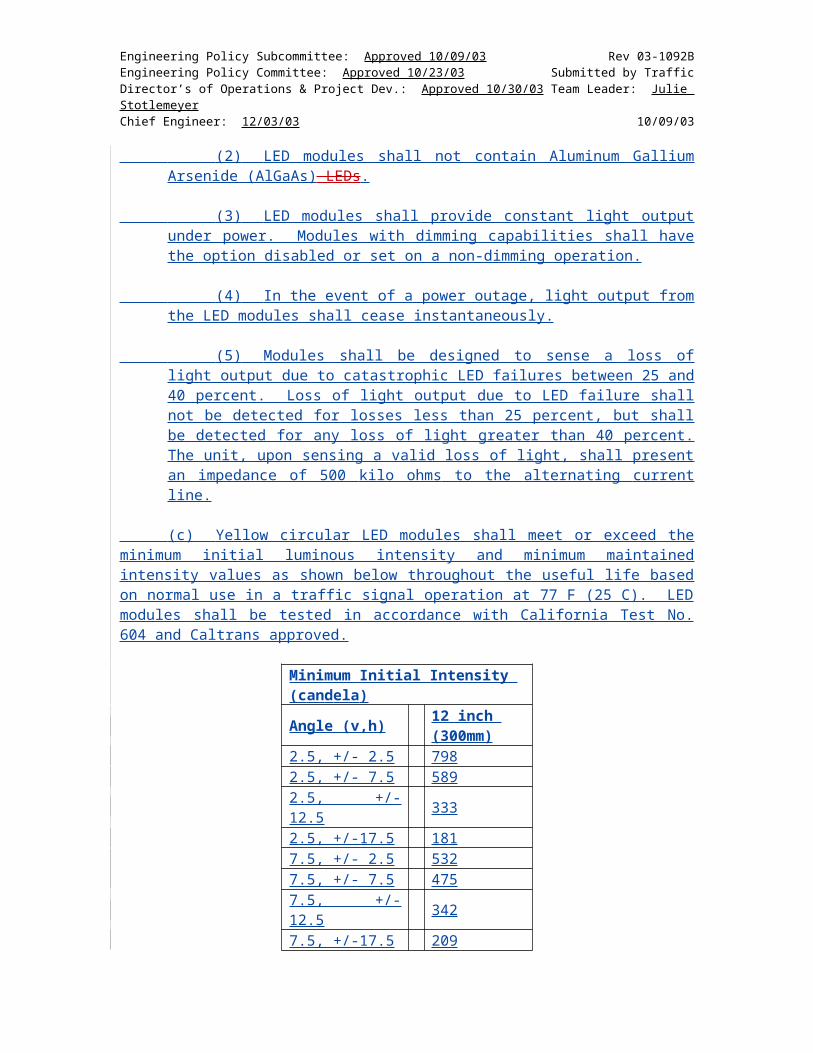


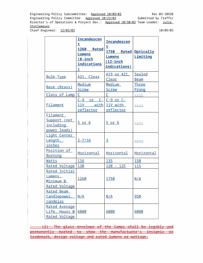


![Section I Doc.docx · Web viewPIN/Postal Code: [insert postal (PIN) code, if applicable] Country: INDIA [The time allowed for the preparation and submission of Bids shall be determined](https://static.documents.pub/doc/80x56/5b0673627f8b9a5c308d014c/section-i-docdocxweb-viewpinpostal-code-insert-postal-pin-code-if-applicable.jpg)


