37
| Date post: | 20-Dec-2015 |
| Category: |
Documents |
| View: | 220 times |
| Download: | 1 times |


Team Members:Noah Van FossanShareen HossainDeepthi ChandraChristina ClemenzLaura Hanley
Advisors:Prof. Mark BellProf. Carla Zoltowski
Project Partner: Prof. Robert Novak
DHA Directional Hearing Aid
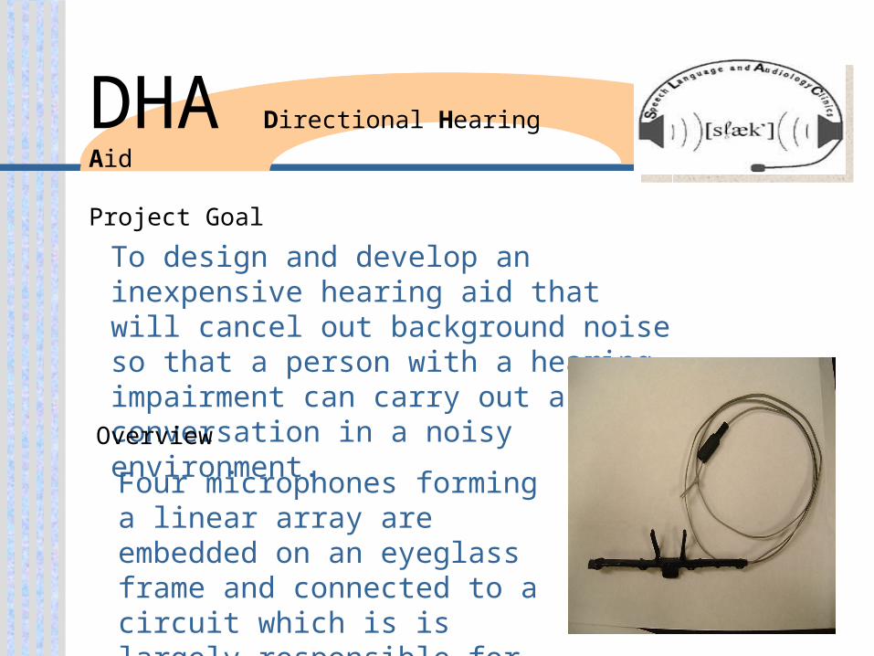
To design and develop an inexpensive hearing aid that will cancel out background noise so that a person with a hearing impairment can carry out a conversation in a noisy environment.
Four microphones forming a linear array are embedded on an eyeglass frame and connected to a circuit which is is largely responsible for the noise cancellation effect.
Project Goal
Overview
DHA Directional Hearing Aid

All microphones must be separated by a fixed distance to produce maximum cancellation of unwanted signals.Input and summing stages must have similar impedances so they do not cause a phase shift inside of the circuit.Having the microphones spaced four centimeters apart increases directionality for high frequencies because of their short wavelength. Low frequencies would require a larger spacing between microphones.
Microphone Array Theory
DHA Directional Hearing Aid
DHA Directional Hearing Aid
The frequency range is from 500Hz to 5.5KHz.
Adjustable lower frequency cutoff switch- 500Hz to 1.5KHz
• Human ear loses high frequency first so more emphasis must be placed upon the base.
Cascading low and high pass filters create the desired frequency range.
Frequency Range Theory

DHA Directional Hearing Aid
• new circuit built, in testing phase
• Increased gain to 45 dB
• Finished auto-off design
• debugging circuit antenna problem
• redesigning the virtual ground
Semester Accomplishments

DHA Directional Hearing Aid
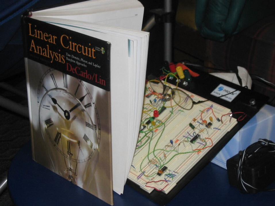
Current Circuit

DHA Directional Hearing Aid
Summing amplifier and High pass stage. • Directionality and low frequency cutoff
occur in this stage
Low pass Stage • High frequencies are cutoff at this
stage.
Gain Stage • The output signal is amplified during
this phase.

DHA Directional Hearing Aid
• Antenna Problem Input
• Voltage leads act as an antenna and is bringing in a frequency of 33KHz
Debugging Process

DHA Directional Hearing Aid
Flaws in Virtual Ground Design
• Large current cannot be drawn from current design
• Gain loss occurs when a load resistance (headphones) is attached
Debugging Process
Current Virtual Ground

DHA Directional Hearing Aid
Solution for antenna problem. • Relocate circuit to protoboard.
New virtual ground design
Proposed Solutions

DHA Directional Hearing Aid
Implementation of auto-off featureFuture Circuit Design
Producing the ProductFuture Semester Goals
DHA Directional Hearing Aid
1. Build Prototype of new circuit
2. Perform various tests
Post prototype lab test
Human subject test
3. Deliver the product


Presented by:Maggie ZhuJason KaedingGreg MooreGuy BarcelonaJamy Archer
Project Partner – Dr. Robert Novak,M. D. Steer Audiology Clinic at Purdue
SEM Sound Exposure Meter

Project Objectives Alert user when
noise level could cause hearing damage
Easy to use, easy to understand
Small size (i.e. a pager)
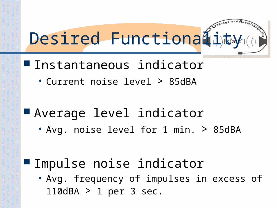
Desired Functionality Instantaneous indicator
• Current noise level > 85dBA
Average level indicator• Avg. noise level for 1 min. > 85dBA
Impulse noise indicator• Avg. frequency of impulses in excess of
110dBA > 1 per 3 sec.
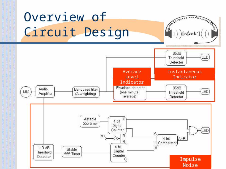
Overview ofCircuit Design
Instantaneous IndicatorAverage Level Indicator
Impulse Noise Indicator
SemesterAccomplishments
Evaluated and consolidated impulse noise indicator section
Redesigned A-weighting filter
Created test plan
Impulse Noise Indicator
Tested current hardware configurations
Consolidated counters and comparator into PLD
Added continuous testing functionality.
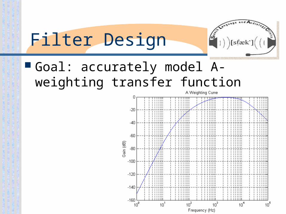
Filter Design Goal: accurately model A-weighting
transfer function
Filter Design Design completed
•Three sections
• Each realizes one part of the transfer curve
• Used active Sallen and Key circuits
•SPICE simulation
• Max. deviation < 0.6dB
Test Plan
Designed for the overall circuit
Includes a standardized procedure and safety concerns
Compares circuit response to the response of Sound Level Meter

Future Plans
Individually test each functional block
Fine tune reference voltages in comparators
Complete new circuit diagram
Implement test plan for whole circuit


Tim ChuahJason FluckeyValerie Lamott
Erica LuteNate Miller
Project Partner – Dr. Robert Novak,M. D. Steer Audiology Clinic at Purdue
VLM Voice Level Meter

Problem Identification
Audiology Clinic needs a visual means of measuring speech volume.
Existing device, Spright II, has been discontinued.

Improvements
Existing device is not very accurate. Longer cord or battery operated. Improve LED display readability.
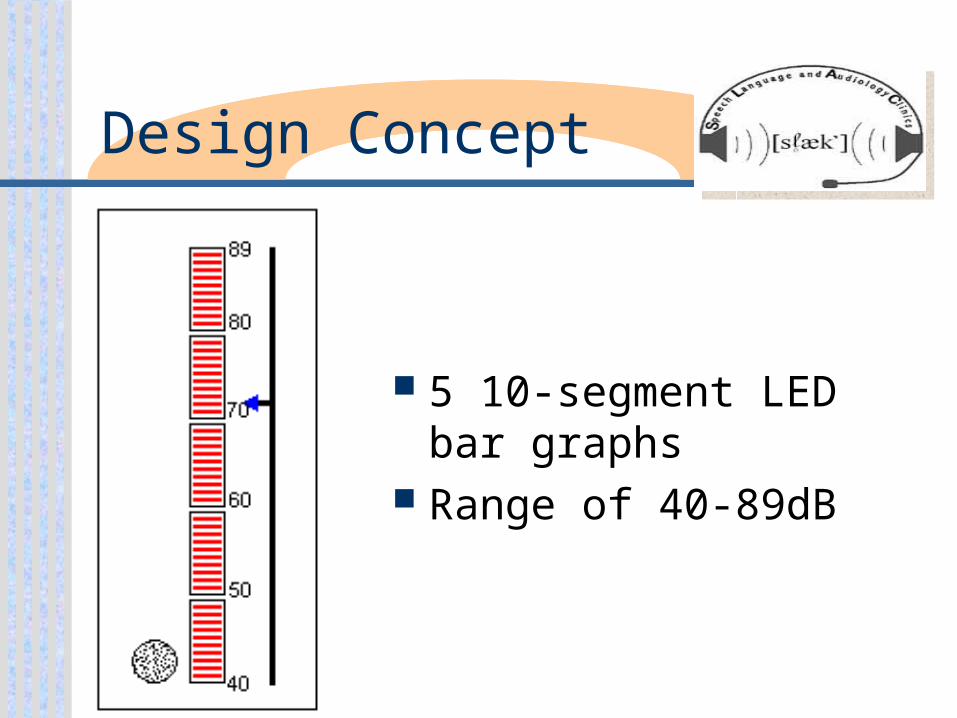
Design Concept
5 10-segment LED bar graphs
Range of 40-89dB

Block Diagram

Circuit Diagram

Project Status
Low pass filter has been built and it works.
Second low pass filter was designed and it also has been built and works.
Log amp has been built and it works. Microphone through log amp
working together
Future Plans
Add potentiometers Work on driver chips Work on casing


