23
This guide has been sponsored by ATG’s Communications & Networking Technology Guide Series Simplified ATM Access at the Customer Premises
| Date post: | 05-Dec-2015 |
| Category: |
Documents |
| Upload: | mahaljagmeet |
| View: | 215 times |
| Download: | 1 times |
This guide has been sponsored by
ATG’s Communications &Networking Technology
Guide Series
SimplifiedATM Access
at the CustomerPremises

Table of ContentsIntroduction. . . . . . . . . . . . . . . . . . . . . . . . . . . . . . . 2ATM Network Access Requirements . . . . . . . . . . . . 4Clear Division of Responsibility Between . . . . . . . . .
Carriers and Users. . . . . . . . . . . . . . . . . . . . . . . . 4Quality of Service (QoS) . . . . . . . . . . . . . . . . . . . . . 7End-to-end Traffic Management . . . . . . . . . . . . . . 10Network and Service Interworking . . . . . . . . . . . . . 12
Methods for Accessing ATM-based WANs . . . . . 12Three Alternatives for Building an ATM-NTU . . . 16Fault Localization: CPE vs. Central Office . . . . . . . 18Management . . . . . . . . . . . . . . . . . . . . . . . . . . . . . 18Media and Rate Conversion . . . . . . . . . . . . . . . . . 18Network and Service Interworking . . . . . . . . . . . . . 19Simplifying the ATM Access Network . . . . . . . . . . 19
Carrier Perspective . . . . . . . . . . . . . . . . . . . . . . . . 23Benefits of the Simplified ATM-NTU and. . . . . . . . .
Interworking-NTU . . . . . . . . . . . . . . . . . . . . . . 23Summary and Conclusions . . . . . . . . . . . . . . . . . 26Case Study 1 . . . . . . . . . . . . . . . . . . . . . . . . . . . . . . 27Case Study 2 . . . . . . . . . . . . . . . . . . . . . . . . . . . . . . 29Glossary of Terms . . . . . . . . . . . . . . . . . . . . . . . . . 31
About the Editor…Gerald P. Ryan is the founder of Connections Telecommunications Inc., a Massa-
chusetts-based company specializing in consulting, education and software tools which
address Wide Area Network issues. Mr. Ryan has developed and taught numerous
courses in network analysis and design for carriers, government agencies and private
industry. Connections has provided consulting support in the areas of WAN network
design, negotiation with carriers for contract pricing and services, technology acquisi-
tion, customized software development for network administration, billing and audit-
ing of telecommunications expenses, project management, and RFP generation. Mr.
Ryan is a member of the Networld+Interop program committee.
This book is the property of The Applied Technologies Group and is made avail-
able upon these terms and conditions. The Applied Technologies Group reserves
all rights herein. Reproduction in whole or in part of this book is only permitted
with the written consent of The Applied Technologies Group. This report shall be
treated at all times as a proprietary document for internal use only. This book may
not be duplicated in any way, except in the form of brief excerpts or quotations
for the purpose of review. In addition, the information contained herein may not
be duplicated in other books, databases or any other medium. Making copies of
this book, or any portion for any purpose other than your own, is a violation of
United States Copyright Laws. The information contained in this report is
believed to be reliable but cannot be guaranteed to be complete or correct.
Copyright © 1997 by The Applied Technologies Group, One Apple Hill,
Suite 216, Natick, MA 01760, Tel: (508) 651-1155, Fax: (508) 651-1171
E-mail: [email protected] Web Site: http://www.techguide.com
Simplified ATM WAN AccessThe ACE-101 extends the service providers ATMmanagement capability to the customer premises,clearly demarcating QoS parameters and respons-ibility between the carrier and the user.
ACE-101 offers Quality of Service control, end-to-endtraffic management, fault localization, and rate andmedia conversion.
Benefits include improved service quality, reducedmaintenance costs and better diagnostics, greater service flexibility, and reduced operating costs.
For more information about RAD’s full range of ATMaccess solutions, contact: [email protected]
www.rad.com
U.S. Headquarters International HeadquartersTel: (201) 529-1100 Tel: 972-3-6458181Fax: (201) 529-5777 Fax: 972-3-6498250
email: [email protected]
E3/T3, STM-1/STS-3C
End-to-End OAMFault ManagementContinuity Check
Performance ManagementLoopback
Customer Premises Customer Premises
ATMUNI
ATMUNI
ATMUNI
SwitchATMUNI
SwitchACE-101
• Monitor• Police
• Monitor• Police
ACE-101ATM
Backbone
As ATM takes its place as the dominant switching fabric
within both carrier networks and very large corporate enterprise
networks, there is a growing need for inexpensive, QoS-enabled
solutions for customer access into an ATM-based wide area
network. Currently, fully configured routers or ATM edge
switches, originally designed for use in a central office, are being
used for this purpose. These devices can perform traffic concen-
tration for large numbers of users, but are most often too big to
support a single site cost-effectively. What is necessary is a
simplified ATM access device to serve as the formal access and
management boundary between the user equipment and the
carrier’s network. There has been a need for an access system
that has a specific application focus, supports QoS to the end
system, promotes simplicity in deployment and management, and
has a superior cost-value ratio. This Guide analyzes this new
requirement and describes the range of functions that such devices
will have to provide. This Guide can help the network developer
to plan the separation between network domains and to specify
the functionality needed at the customer interface point.
IntroductionAsynchronous Transfer Mode (ATM) networks are
capable of simultaneously transporting voice, data,
graphic and video content at very high speeds, with
well-defined qualities of service (QoS), using advanced
cell-based switching techniques. Support for real time
multimedia applications and the promise of better
scalability, flexibility and integration make ATM the
pervasive switching technology for next generation
wide area networks. Network service providers are
moving quickly both to make ATM the dominant
infrastructure for the core of their wide area networks
and also to implement access to the ATM networks
directly from customer premises.
2 • Simplified ATM Access at the Customer Premises
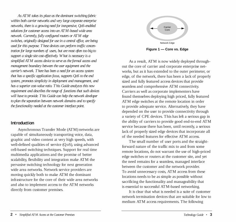
As a result, ATM is now widely deployed through-
out the core of carrier and corporate enterprise net-
works, but as it has extended to the outer perimeter, or
edge, of the network, there has been a lack of properly
sized and fully featured access devices that provide
seamless and comprehensive ATM connectivity.
Carriers as well as corporate implementers have
found themselves deploying high priced, fully featured
ATM edge switches at the remote location in order
to provide adequate service. Alternatively, they have
depended on the user to provide connectivity through
a variety of CPE devices. This has left a serious gap in
the ability of carriers to provide good end-to-end ATM
service because there has been, until recently, a serious
lack of properly sized edge devices that incorporate all
of the needed features for effective ATM access.
The small number of user ports and the straight-
forward nature of the traffic mix to and from some
remote locations, do not warrant the use of high-priced
edge switches or routers at the customer site, and yet
the need remains for a seamless, managed interface
between the customer and the network provider.
To avoid unnecessary costs, ATM access from these
locations needs to be as simple as possible without
sacrificing the functionality and manageability that
is essential to successful ATM-based networking.
It is clear that what is needed is a suite of customer
network termination devices that are suitable for low to
medium ATM access requirements. The following
Network Edge
Figure 1 — Core vs. Edge
CarrierCore
Technology Guide • 3
sections examine the issues involved in providing such
devices and identifies the key benefits of formalizing
the customer interface into a simple, low cost, fully
functioned and manageable network termination unit
(NTU).
ATM Network Access RequirementsIn addition to the requirement that access devices
be properly sized and priced to accommodate the
needs of different size locations, customer premises
ATM access devices must also allow:
• Clear division of responsibility between carriers
and users
• QoS control
• End-to-end traffic management
• Fault localization (CPE vs. Central Office)
• Service flexibility—media and rate conversion
Clear Division of Responsibility BetweenCarriers and Users
Any network can be divided into three distinct
parts: the customer premises equipment (CPE), the
access connection that links the customer to the carrier
central office, and the carrier core network infrastruc-
ture used for interoffice transport. Each of these three
parts could be used to provide the access interface into
the ATM core since each serves as a natural boundary
that can be used for ATM adaptation, the conversion
of network media and traffic rates, as well as opera-
tional management and administration.
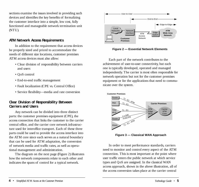
The diagram on the next page (Figure 2) illustrates
how the network components relate to each other and
indicates the spans of control for a typical network.
4 • Simplified ATM Access at the Customer Premises Technology Guide • 5
Each part of the network contributes to the
achievement of user-to-user connectivity, but each
one is typically developed, operated and managed
independently. The carrier is most often responsible for
network operation but not for the customer premises
equipment or for the applications that need to commu-
nicate over the system.
In order to meet performance standards, carriers
need to monitor and control every aspect of the ATM
connection. This is most important at the point where
user traffic enters the public network at which service
types and QoS are assigned. In the classical WAN
access approach, shown in the above illustration, all of
the access conversion takes place at the carrier central
Figure 3 — Classical WAN Approach
Customer Premises
Carrier Premises
Router
T1 - E1 - A
TM
T1 - E1 - ATM T1 - E1
T1 - E1
n x 64K
FUNI/FR
PBX
TDMMUX
ATMEdgeMUX
CarrierATMCore
Router
FRAD
ATMWide AreaNetwork
Figure 2 — Essential Network Elements
EdgeSwitch
CustomerPremises
NetworkInterface ATM
Access Network
LocalNetworks
Edge-to-Edge
End-to-End
User-to-User
office where native traffic is converted to ATM. This,
unfortunately, does not allow end-to-end control but
only edge-to-edge (from central office to central office).
Also, the CPE oftentimes fails to provide appropriate
traffic management capabilities since it was designed
for use in a LAN environment and does not have the
monitoring and control capabilities to support WAN
access. As a result, carriers need to identify, and have
available for widespread deployment, a cost efficient,
highly functional NTU for use at the customer
premises.
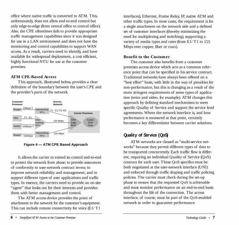
ATM CPE-Based Access
This approach, illustrated below, provides a clear
definition of the boundary between the user’s CPE and
the provider’s parts of the network.
It allows the carrier to extend its control end-to-end
to protect the network from abuse; to provide assurances
of conformity to user-network contract terms; to
improve network reliability and management; and to
support different types of user applications and traffic
types. In essence, the carriers need to provide an on-site
“agent” that looks out for their interests and provides
them with better management and control.
The ATM access device provides the point of
attachment to the network for the customer’s equipment.
This can include remote connectivity for voice (E1/T1
Figure 4 — ATM CPE Based Approach
CustomerPremises
AccessNetwork
Carrier Premises
Router
PBX
InterworkingNTU
InterworkingNTU
Inter-workingNTUSwitch
ATMEdgeMUX
CarrierATMCore
Router
10Base T
T1 - E1155 Mbps
T1 - E1/T3 -E3
155 Mbps
100Base T
155Mbps
6 • Simplified ATM Access at the Customer Premises Technology Guide • 7
interfaces), Ethernet, Frame Relay, IP, native ATM and
other traffic types. In most cases, the requirement is for
a single attachment on the network side and a defined
set of customer interfaces (thereby minimizing the
need for multiplexing and switching), supporting a
variety of media types and rates (from E1/T1 to 155
Mbps over copper, fiber or coax).
Benefit to the Customer
The customer also benefits from a customer
premises access device which acts as a common refer-
ence point that can be specified in his service contract.
Traditional networks have always been offered on a
“best effort” basis, with little in the way of penalties for
non-performance, but this is changing as a result of the
more stringent requirements of some types of applica-
tion (voice and video, for example). ATM changes this
approach by defining standard mechanisms to meet
specific Quality of Service and support the service level
agreements. Where the network interface is, and how
performance is measured at that point, certainly
becomes a key differentiator between carrier solutions.
Quality of Service (QoS)ATM networks are classed as “multi-service net-
works” because they permit different types of data to
be transported concurrently. Each traffic flow is differ-
ent, requiring an individual Quality of Service (QoS)
contract for each user. These QoS specifics must be
both negotiated at the user-network interface (UNI)
and enforced through traffic shaping and traffic policing
policies. The carrier must check during the set-up
phase to ensure that the requested QoS is achievable
and must monitor performance on an end-to-end basis
throughout the life of the connection. The access
interface, of course, must be part of the QoS-enabled
network in order to guarantee performance.

8 • Simplified ATM Access at the Customer Premises
These QoS classes are implemented on the Virtual
Channels (VCs) that are established as the traffic path
through the network between end points. The QoS
standards essentially result in rules governing these key
performance criteria:
Localized Parameters—Measured at the CPE
interface (the point where user traffic enters
the public service)
• Peak Cell Rate (PCR)—The maximum cell
transfer rate allowed at the interface
• Sustainable Cell Rate (SCR)—The average cell
transfer rate allowed at the interface
• Cell Delay Variation Tolerance (CDVT)—The
“jitter”, or mean variation in the inter-cell timing
• Minimum Cell Rate (MCR)—The lowest cell
transfer rate allowed at the interface
• Burst Size (BS)—The maximum number of cells
that can be transmitted at the peak cell rate
Network Parameters—Measured between two
points in the network
• Cell Delay—Maximum allowable end-to-end cell
delay
• Cell Delay Variation—Maximum allowable
variation in cell delay
• Cell Loss—Maximum allowable percentage of
traffic that can be lost or discarded.
The ATM access device enables traffic conformity
checks to be performed at the point where user traffic
enters the public network by letting carriers monitor
these localized parameters. It also provides a user-
oriented point of observation where end-to-end
measurements of cell delay, cell delay variation and
Technology Guide • 9
QoS Management
Each data stream from a user device must declare
its requirements for QoS every time a virtual channel
or virtual path connection is established. This is accom-
plished via ATM signaling at the UNI.
Four categories of QoS have been defined for
ATM services:
• Constant Bit Rate (CBR) offers strict bandwidth
guarantees and minimal delay and delay varia-
tion. It is suitable for real time applications such
as telephony and video. It is intended to be the
equivalent of digital leased line service. This class
of service can not tolerate delay or loss.
• Variable Bit Rate (VBR) which is suited to LAN
interconnection and similar applications that do
not make stringent demands on bandwidth, delay
or delay variation. Within the category, the ATM
forum has defined real time (RT) and non-real
time (NRT) traffic. VBR-RT is close to CBR in
terms of its specifications and is intended for time
sensitive applications that can tolerate some mini-
mal variation in delay or cell loss. The VBR-NRT
is used for applications such as on line transaction
processing and static video.
• Available Bit Rate (ABR) makes use of the band-
width that is available from moment to moment
for applications such as file transfer that can
tolerate low priority handling, but which still need
minimal cell loss. These applications are not as
time sensitive and therefore can be superseded by
more time sensitive applications.
• Unspecified Bit Rate (UBR) is an economical class of
service, which is similar to ABR in that it uses
available bandwidth on a moment to moment
basis, but without service level guarantees.
cell loss can be taken. Without the access device the
carrier is restricted to edge-to-edge measurements (cen-
tral office to central office). The ability to efficiently
monitor and report upon what is happening is funda-
mental to network management as well as QoS control
and traffic assurance.
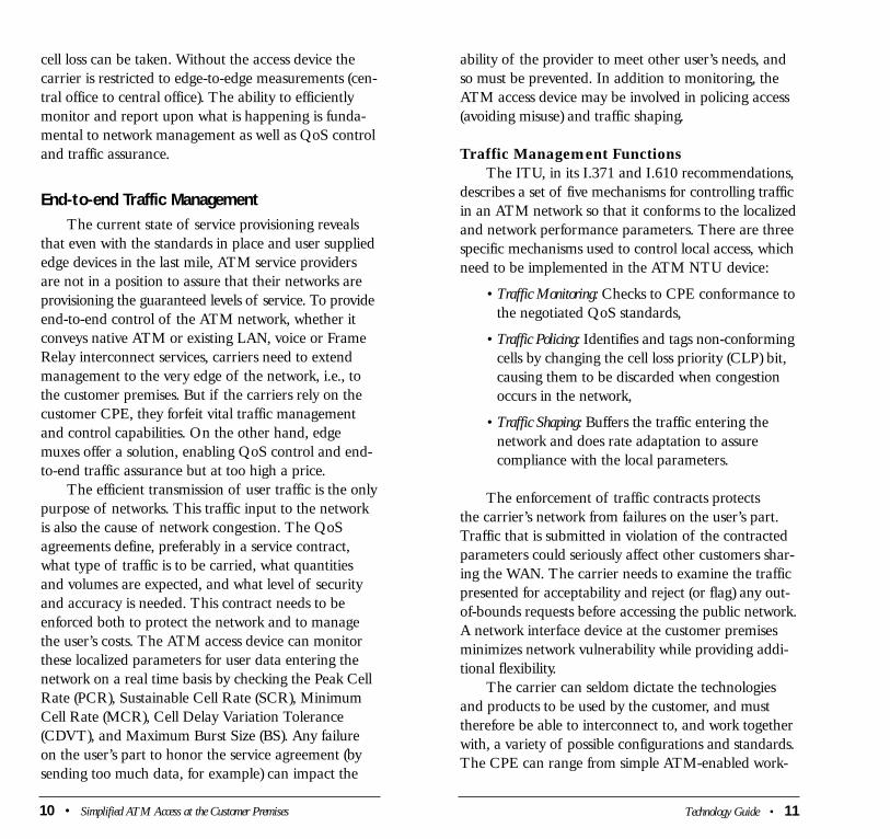
End-to-end Traffic ManagementThe current state of service provisioning reveals
that even with the standards in place and user supplied
edge devices in the last mile, ATM service providers
are not in a position to assure that their networks are
provisioning the guaranteed levels of service. To provide
end-to-end control of the ATM network, whether it
conveys native ATM or existing LAN, voice or Frame
Relay interconnect services, carriers need to extend
management to the very edge of the network, i.e., to
the customer premises. But if the carriers rely on the
customer CPE, they forfeit vital traffic management
and control capabilities. On the other hand, edge
muxes offer a solution, enabling QoS control and end-
to-end traffic assurance but at too high a price.
The efficient transmission of user traffic is the only
purpose of networks. This traffic input to the network
is also the cause of network congestion. The QoS
agreements define, preferably in a service contract,
what type of traffic is to be carried, what quantities
and volumes are expected, and what level of security
and accuracy is needed. This contract needs to be
enforced both to protect the network and to manage
the user’s costs. The ATM access device can monitor
these localized parameters for user data entering the
network on a real time basis by checking the Peak Cell
Rate (PCR), Sustainable Cell Rate (SCR), Minimum
Cell Rate (MCR), Cell Delay Variation Tolerance
(CDVT), and Maximum Burst Size (BS). Any failure
on the user’s part to honor the service agreement (by
sending too much data, for example) can impact the
10 • Simplified ATM Access at the Customer Premises
ability of the provider to meet other user’s needs, and
so must be prevented. In addition to monitoring, the
ATM access device may be involved in policing access
(avoiding misuse) and traffic shaping.
Traffic Management Functions
The ITU, in its I.371 and I.610 recommendations,
describes a set of five mechanisms for controlling traffic
in an ATM network so that it conforms to the localized
and network performance parameters. There are three
specific mechanisms used to control local access, which
need to be implemented in the ATM NTU device:
• Traffic Monitoring: Checks to CPE conformance to
the negotiated QoS standards,
• Traffic Policing: Identifies and tags non-conforming
cells by changing the cell loss priority (CLP) bit,
causing them to be discarded when congestion
occurs in the network,
• Traffic Shaping: Buffers the traffic entering the
network and does rate adaptation to assure
compliance with the local parameters.
The enforcement of traffic contracts protects
the carrier’s network from failures on the user’s part.
Traffic that is submitted in violation of the contracted
parameters could seriously affect other customers shar-
ing the WAN. The carrier needs to examine the traffic
presented for acceptability and reject (or flag) any out-
of-bounds requests before accessing the public network.
A network interface device at the customer premises
minimizes network vulnerability while providing addi-
tional flexibility.
The carrier can seldom dictate the technologies
and products to be used by the customer, and must
therefore be able to interconnect to, and work together
with, a variety of possible configurations and standards.
The CPE can range from simple ATM-enabled work-
Technology Guide • 11
12 • Simplified ATM Access at the Customer Premises Technology Guide • 13
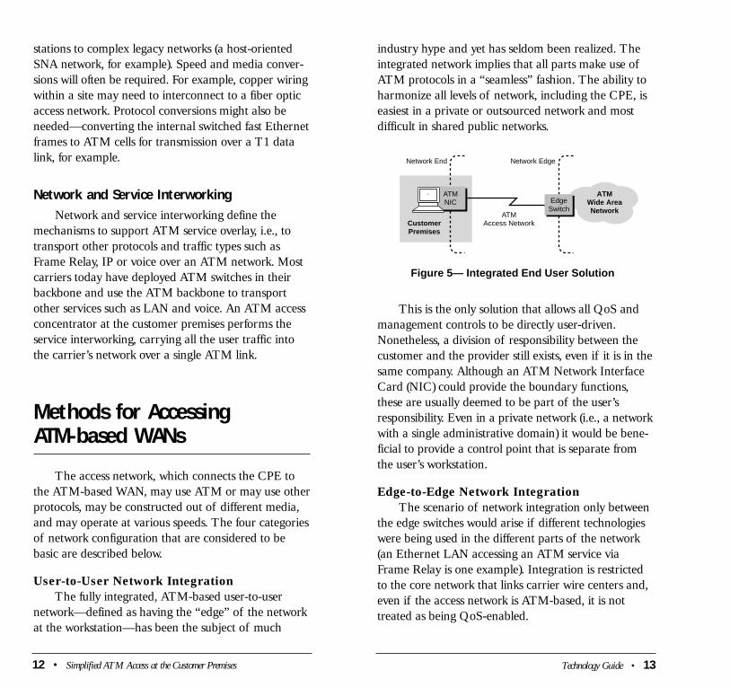
industry hype and yet has seldom been realized. The
integrated network implies that all parts make use of
ATM protocols in a “seamless” fashion. The ability to
harmonize all levels of network, including the CPE, is
easiest in a private or outsourced network and most
difficult in shared public networks.
This is the only solution that allows all QoS and
management controls to be directly user-driven.
Nonetheless, a division of responsibility between the
customer and the provider still exists, even if it is in the
same company. Although an ATM Network Interface
Card (NIC) could provide the boundary functions,
these are usually deemed to be part of the user’s
responsibility. Even in a private network (i.e., a network
with a single administrative domain) it would be bene-
ficial to provide a control point that is separate from
the user’s workstation.
Edge-to-Edge Network Integration
The scenario of network integration only between
the edge switches would arise if different technologies
were being used in the different parts of the network
(an Ethernet LAN accessing an ATM service via
Frame Relay is one example). Integration is restricted
to the core network that links carrier wire centers and,
even if the access network is ATM-based, it is not
treated as being QoS-enabled.
ATMWide AreaNetwork
Figure 5— Integrated End User Solution
Network End
CustomerPremises
ATMAccess Network
Network Edge
EdgeSwitch
ATMNIC
stations to complex legacy networks (a host-oriented
SNA network, for example). Speed and media conver-
sions will often be required. For example, copper wiring
within a site may need to interconnect to a fiber optic
access network. Protocol conversions might also be
needed—converting the internal switched fast Ethernet
frames to ATM cells for transmission over a T1 data
link, for example.
Network and Service InterworkingNetwork and service interworking define the
mechanisms to support ATM service overlay, i.e., to
transport other protocols and traffic types such as
Frame Relay, IP or voice over an ATM network. Most
carriers today have deployed ATM switches in their
backbone and use the ATM backbone to transport
other services such as LAN and voice. An ATM access
concentrator at the customer premises performs the
service interworking, carrying all the user traffic into
the carrier’s network over a single ATM link.
Methods for Accessing ATM-based WANs
The access network, which connects the CPE to
the ATM-based WAN, may use ATM or may use other
protocols, may be constructed out of different media,
and may operate at various speeds. The four categories
of network configuration that are considered to be
basic are described below.
User-to-User Network Integration
The fully integrated, ATM-based user-to-user
network—defined as having the “edge” of the network
at the workstation—has been the subject of much

The edge of the network would be the ATM
switch, not the customer’s premises. The access network
could be treated as the user’s responsibility or it may
not support QoS controls at all. The service provider
provides edge-to-edge service level guarantees but
cannot ensure end-to-end performance.
End-to-End Network Integration
The third category of access method places
the “edge” of the carrier’s network in the customer
premises, at the end of the WAN but not all the way
to the workstation. The access network can either be a
separate, interconnected sub-network under the control
of the carrier, such as a Frame Relay, or can be treated
as an extension of the core WAN switch. These two
alternatives are illustrated below and on the next page.
ATMWide AreaNetwork
Figure 7 —Carrier Supplied Customer Premises Access Device
Network End Network Edge
CustomerPremises
ATM or non-ATMAccess Network
EdgeSwitch
Router orLAN Switch
ATMWide AreaNetwork
Figure 6 — Edge Switch-Based Implementation
Network EndNetwork Edge
CustomerPremises
ATM Network
Network Switch or
Edge Switch
EdgeSwitch
14 • Simplified ATM Access at the Customer Premises
Placing a large edge switch in the customer
premises would be analogous to using a PBX in
telephony. It extends the WAN and dedicates a fully
functional network node to the customer. Since this is
a relatively expensive solution, it would be targeted to
the needs of larger offices or buildings. It might also
be used in very complex networks requiring a variety
of voice, data and multimedia interfaces to be concen-
trated over the same access network.
Establishing the customer’s site as an extension
of the central office has some advantages (such as
allowing multiple input) but there are also constraints.
For example maintaining a complex, carrier owned
switch that is remote from the central office is more
time consuming and may lack diagnostic and fault
management capabilities normally found in the customer
premises equipment. In summary, the premises-based
edge switch, while suitable for larger organizations
that warrant a full-featured, high-cost device, is not
cost-effective for smaller offices.
A variation on this theme is illustrated below.
In this case some functions of the edge switch are
located at the customer premises while other remain at
the central office. This effectively creates a distributed
edge switch—much the way an ISDN connection
distributes some functionality to the terminal adapter.
ATMWide AreaNetwork
Figure 8 —Carrier Supplied ATM NTU/Internetworking NTU
Network EndNetwork Edge
CustomerPremises
ATM Access Network
EdgeSwitch
ATM NTU orInternetworking
NTU
Technology Guide • 15
16 • Simplified ATM Access at the Customer Premises Technology Guide • 17
access to or control over the customer’s equipment,
and may not even be familiar with its operation.
Responsibilities for service restoration in a failure
situation are not clear. The carrier would certainly be
unable to perform moves, adds and changes without
considerable coordination with the customer. The need
for testing for conformance to standards would also
need to be ongoing, since changes in either end can
affect the other. This approach is seldom satisfactory
except in a centrally controlled private network (where
all components are under the control of a single
manager). Even in this case the switches will not be
able to support and control QoS and will not be able
to prevent users from affecting one another.
Provide a low-cost network termination device
at the customer site.
An ATM-NTU is a fixed function device whose
role is to create the formal boundary between the
network-provided components and the customer’s
equipment. It would not replace the carrier edge
switch but will simplify its operation. The ATM-NTU
supports the provider’s needs for remote monitoring
and control of the access network without duplicating
expensive switching functions. It acts as a guard—
checking and possibly correcting the user traffic that
is entering the public network.
An Interworking-NTU is similar to an ATM-NTU,
performing all the functionality described above: traffic
monitoring and control. In addition it performs concen-
tration of multiple services (voice, LAN, Frame Relay,
ATM, etc.) over a single ATM link. Most offices have
routers, Frame Relay multiplexers, PBXs and other
legacy devices. The Interworking NTU concentrates
the heterogeneous traffic types from all these devices
over a single ATM link.
A carrier owned, special-purpose network termina-
tion unit (NTU) located at the customer premises is
a solution that satisfies many of the requirements
discussed earlier. ATM functions, as well as network
interworking, can be provided as close as possible to the
user source, the size and complexity of the ATM edge
switch will be reduced since many functions will occur
at the NTU and the overall cost of operation will be
lower.
Three Alternatives for Building an ATM-NTU
Use a provider-supplied edge router or switch
in the customer premises.
The carrier could install a full edge switch or a
router to support the local networking environment (the
end-to-end integration approach). The switch needs to
be modular and scaleable enough to handle physical
moves, adds and changes. It would need to be config-
urable to support a wide range of protocols (whether
the customer has the need or not) and manageable
both remotely and locally. The owner of the switch
must manage and control faults and performance from
end-to-end, identify and report user errors and allow
integration with customer management systems.
Current edge switching solutions are intended for heavy
traffic, multiple applications, traffic monitoring, band-
width grooming and shaping, and VC management.
Multiple modular platforms and the heavy processing
power required to perform the QoS tests on a per cell
per customer basis make this an expensive solution.
Use an existing user LAN or workgroup switch
interface.
The carrier could rely on the ATM capabilities
of the CPE to provide a network interface point. This,
however, does not establish a stable reference point for
service access. The carrier is unlikely to have remote
Fault Localization: CPE vs. Central OfficeOne of the key issues in network control and diag-
nostics is the ability to isolate performance difficulties
between the customer CPE and the network. By having
the correct, fully functional NTU device located on the
customer premises, carriers can quickly identify the
source of network problems. The network management
equipment that is implemented both in the carrier and
the private network environment is usually built around
the SNMP protocol and its associated operational suite
of tools. By incorporating these functions within the
ATM NTU architecture, carriers are able to identify
the source of problems in the general sense and can
localize problems according to their nature and appli-
cation.
ManagementNTU devices that support the SNMP management
protocol and standard SNMP MIBs together with a
mature and intuitive GUI interface should support
both UNIX and PC based platforms. This helps to
insure the ability to integrate management into an
existing backbone management platform, enabling
centralized management and maintenance functional-
ity such as remote firmware download and diagnostics.
Media and Rate ConversionRate Conversion is accomplished between dissimilar
interfaces by extracting ATM cells from one interface
at one speed and sending them over a second interface
at another speed. For example, rate conversion could
enable the connection of an OC-3 155 Mbps fiber
interface to a T-3 or E-3 carrier interface. Effective
NTU devices use high capacity buffering with multiple
levels of priorities to convert between rates and signal
types, while preserving the Virtual Channel and Virtual
Path traffic characteristics. CBR traffic is assigned to
18 • Simplified ATM Access at the Customer Premises
the high priority queue while VBR –RT to a lower
priority, then VBR-NRT lower still, and finally UBR
traffic to the lowest priority. Media conversion, which
essentially allows the interoperability between diverse
media type such as fiber, or twisted pair copper wire,
requires that interconnectivity happen at the lowest,
electrical, layer of the protocol stack. This addresses
the nature of the physical port configuration as well as
the method used to propagate a signal. For example,
fiber typically uses the SONET signaling architecture
which is different from what is used for T1 or E1. A
properly equipped NTU has the capacity to intercon-
nect a wide range of media and rate characteristics
and assure effective end-to-end signaling.
Network and Service InterworkingAlmost every office has multiple networking
devices: PBX for voice connectivity, routers for LAN
traffic, possibly Frame Relay access devices to concen-
trate voice and data traffic over a single link or even
ATM LAN switches. The ATM access device should
be able to simultaneously support several of these
applications and concentrate the different traffic sources
over a single ATM link. This simplifies the user-carrier
relationship: service billing, installation and control, by
limiting them to a single link and a single service.
Simplifying the ATM Access NetworkThe key to simplifying any network is to provide
a comprehensive management system that covers all
parts of the network, and which provides a clear division
of authority among the network’s managers and crisp
specifications for the services to be provided. The most
critical division, between the customer and the carrier,
is where an ATM-NTU or Interworking-NTU can be
utilized.
Technology Guide • 19
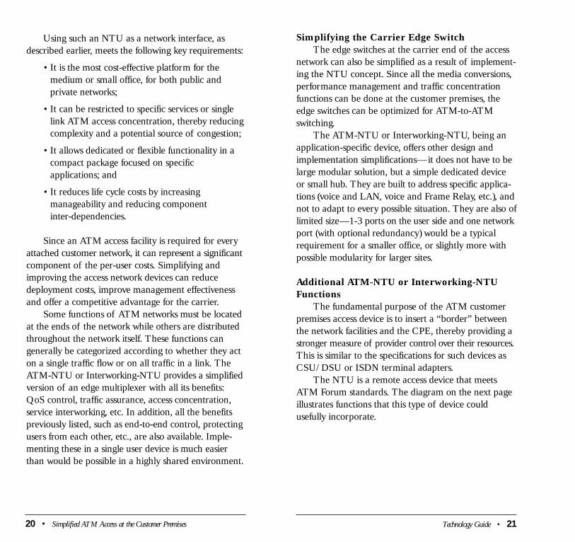
Using such an NTU as a network interface, as
described earlier, meets the following key requirements:
• It is the most cost-effective platform for the
medium or small office, for both public and
private networks;
• It can be restricted to specific services or single
link ATM access concentration, thereby reducing
complexity and a potential source of congestion;
• It allows dedicated or flexible functionality in a
compact package focused on specific
applications; and
• It reduces life cycle costs by increasing
manageability and reducing component
inter-dependencies.
Since an ATM access facility is required for every
attached customer network, it can represent a significant
component of the per-user costs. Simplifying and
improving the access network devices can reduce
deployment costs, improve management effectiveness
and offer a competitive advantage for the carrier.
Some functions of ATM networks must be located
at the ends of the network while others are distributed
throughout the network itself. These functions can
generally be categorized according to whether they act
on a single traffic flow or on all traffic in a link. The
ATM-NTU or Interworking-NTU provides a simplified
version of an edge multiplexer with all its benefits:
QoS control, traffic assurance, access concentration,
service interworking, etc. In addition, all the benefits
previously listed, such as end-to-end control, protecting
users from each other, etc., are also available. Imple-
menting these in a single user device is much easier
than would be possible in a highly shared environment.
20 • Simplified ATM Access at the Customer Premises Technology Guide • 21
Simplifying the Carrier Edge Switch
The edge switches at the carrier end of the access
network can also be simplified as a result of implement-
ing the NTU concept. Since all the media conversions,
performance management and traffic concentration
functions can be done at the customer premises, the
edge switches can be optimized for ATM-to-ATM
switching.
The ATM-NTU or Interworking-NTU, being an
application-specific device, offers other design and
implementation simplifications—it does not have to be
large modular solution, but a simple dedicated device
or small hub. They are built to address specific applica-
tions (voice and LAN, voice and Frame Relay, etc.), and
not to adapt to every possible situation. They are also of
limited size—1-3 ports on the user side and one network
port (with optional redundancy) would be a typical
requirement for a smaller office, or slightly more with
possible modularity for larger sites.
Additional ATM-NTU or Interworking-NTU
Functions
The fundamental purpose of the ATM customer
premises access device is to insert a “border” between
the network facilities and the CPE, thereby providing a
stronger measure of provider control over their resources.
This is similar to the specifications for such devices as
CSU/DSU or ISDN terminal adapters.
The NTU is a remote access device that meets
ATM Forum standards. The diagram on the next page
illustrates functions that this type of device could
usefully incorporate.
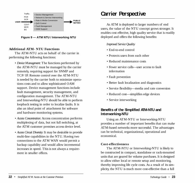
Additional ATM- NTU Functions
The ATM-NTU acts on behalf of the carrier in
performing the following functions:
• Device Management: The functions performed by
the ATM-NTU must be managed by the carrier
remotely, requiring support for SNMP and
TCP/IP. Remote control over the ATM-NTU
is needed by the carrier both to minimize opera-
tions costs and to allow sophisticated OAM
support. Device management functions include
fault management, security management, and
configuration management. The ATM-NTU
and Interworking-NTU should be able to perform
loopback testing in order to localize faults. It is
also an ideal point of attachment for software
and hardware monitoring systems.
• Access Concentration: Access concentration performs
multiplexing of data, but not full switching, at
the ATM customer premises access device level.
• Access Circuit Diversity: It may be desirable to provide
multi-line capabilities in the NTU. Having two
connections to the ATM WAN would permit a
backup capability and would allow incremental
increases in speed. This is not always a require-
ment in smaller offices.
Figure 9 — ATM NTU / Interworking NTU
USER
• Device Management
• Network & Service Interworking
• Rate & Media Conversion
• QoS Control
• Fault Management
• OAM Support
Traffic:
PCRSCR
CDVTMCRBS
PUBLICNETWOR
22 • Simplified ATM Access at the Customer Premises
Carrier Perspective
As ATM is deployed to larger numbers of end
users, the value of the NTU concept grows stronger. It
enables cost effective, high quality service that is readily
deployed and offers the following benefits:
Improved Service Quality
• End-to-end control
• Protects users from each other
• Reduced maintenance costs
• Fewer service calls—user access to fault
information
• Fault prevention
• Better fault localization and diagnostics
• Service flexibility—media and rate conversion
• Reduced cost—simplifies edge devices
• Service interworking
Benefits of the Simplified ATM-NTU andInterworking-NTU
Using an ATM-NTU or Interworking-NTU
provides a number of important benefits that can make
ATM-based networks more successful. The advantages
can be technical, organizational, operational and
economical.
Cost-effectiveness
The ATM-NTU or Interworking-NTU is likely to
be constructed in compact, standalone or rack-mounted
units that are geared for volume purchases. It is designed
to allow either local or remote setup and monitoring,
thereby improving life cycle costs. As a result of its sim-
plicity, the NTU is much more cost-effective than a full
Technology Guide • 23
edge switch for its target market.
Also contributing to the cost-effectiveness is the
fact that by performing all the functionality at the
customer premises simplifies the operation of edge
switches—they no longer need to support multiple
technologies to perform the access concentration. They
only have to “know” ATM both on the user side and
on the network side. This reduces the cost of the edge
multiplexes and reduces the overall cost of the ATM
network for the carrier.
Network Management
Perhaps the most significant advantage of the
ATM-NTU or Interworking-NTU is its potential as a
tool for managing the network. Having a well-defined
boundary between the user and provider reduces
management finger-pointing and provides test and
monitoring access at a point which represents a common
view for both user and provider.
The ATM-NTU can also help to separate archi-
tecture and planning decisions. Things on one side of
the device are less dependent on what’s on the other
side. Without an ATM-NTU the service provider would
need to be involved in upgrades and changes to the
user’s interface equipment which, in a large network,
can become a costly exercise. It is therefore a more
effective growth path for service deployment.
Supporting rate and media conversions, including
the ability to handle the various flavors of ATM,
provides greater flexibility. This can make network
transitions and upgrades easier to plan and to justify.
User-Provider Relationship
The advantages of an ATM-NTU or Interworking-
NTU can also be understood by examining the benefits
from the service provider’s and the user’s perspective.
The NTU provides the necessary separation
between the user portion of the network and the
24 • Simplified ATM Access at the Customer Premises
provider’s portion, thereby allowing end-to-end control
and management by the provider. The NTU is a point
where traffic is formally handed over to the network—
but only if it conforms to contract characteristics.
Protecting the network from abuse has to be a primary
consideration of the network provider. The use of an
NTU approach meets both these needs at an acceptable
cost.
Achieving control over the traffic coming onto the
network at the customer premises reduces the load on
the access network, avoids overhead in the ATM access
network switch, and ensures lower overall costs. Faults
can be localized more easily, and additional monitoring
points can be provided.
Assuring QoS conformance at the customer site
leads to better service, ease of deployment and lower
cost.
The network termination unit, which serves as the
provider’s “representative” at the customer site, should
also be able to identify user problems and report them
to the manager, thereby providing traffic assurance up
to the customer premises.
The network user, of course, wants a problem-free
environment that satisfies the organization’s require-
ments for speed, QoS, and accessibility. The availability
of the ATM-NTU or Interworking-NTU allows better
service and problem resolution, isolation from other
users, flexibility of service media, lower cost, speedy
deployment, elegant and simple solution, and a custom
fit.
Technology Guide • 25

Summary and Conclusions
Customer premises access devices such as ATM
NTUs or Interworking-NTUs extend carrier control to
the customer premises bringing important benefits such
as increased user satisfaction, lower maintenance costs,
flexibility of service offerings and greater service assur-
ances. The ATM NTU functionality can be accommo-
dated in a suite of interface access devices, enabling
the carrier to have standard control of both native
ATM and multi-service contracts.
It has been claimed that ATM cell switching is a
major step forward in the evolution of networks. ATM-
based WANs allow network service providers to offer
multi-service, multi-protocol, QoS-enabled transport
capabilities, thereby providing a platform for a new
generation of distributed applications. Since both large
and small offices will require access to ATM networks,
the need for scalability in an ATM network access
device is evident.
Today’s solutions for user access to ATM can be
too costly and over-sized for many of today’s needs. An
elegant and cost-effective solution is the ATM-NTU or
Interworking-NTU. It has been shown that the ATM-
NTU provides an answer that meets the need. It is easy
to deploy, sized right for its task, provides QoS support,
and is easily managed remotely.
The ATM-NTU supports the traditional network
provider’s requirement to maintain control over their
resources and to protect the network against misuse.
But it is also beneficial to end users who want end-to-
end support.
26 • Simplified ATM Access at the Customer Premises Case Study • 27
CASE STUDY 1:Efficient and Simple Control of ATM Quality of Service
Following large-scale ATM service trials, and prior
to rolling out nationwide and international native
ATM services, a major European carrier determined
the need for a carrier owned and controlled ATM
Network Termination Unit to be provisioned at the
interface between the customer premises and the public
ATM network. This would serve as the demarcation
point between the ATM environment at the customer
premises and the carrier’s network. The device had to
be QoS enabled, offer a superior cost-performance
ratio, and support a minimum number of VP/VCs (256).
The carrier also required that flexible LAN/WAN con-
nectivity options be built into the device, for maximum
on-the-spot compatibility between diverse end user
equipment and carrier transmission interfaces.
The ACE-101 answers all these specifications. In
particular, ACE-101 satisfies the carrier’s requirements
for implementing Operation, Administration and
Maintenance (OAM) support for end-to-end ATM
service monitoring, including Continuity Check (CC),
Alarm Indication Signal (AIS), and Remote Defect
Indication (RDI).
ACE-101 also provides Performance Management
(PM) features, checking peak cell rate, cell delay varia-
tion tolerance, sustainable cell rate, and maximum burst
size of traffic entering the public network. Loopback
cells are used to measure cell loss and cell delay para-
meters end to end.
Of special interest to the carrier is the ACE-101’s
ability to carry out “Reverse PM,” collecting statistics
on what is transmitted by the NTU into the network
as well as information on what is received from the
customer premises into the NTU device.
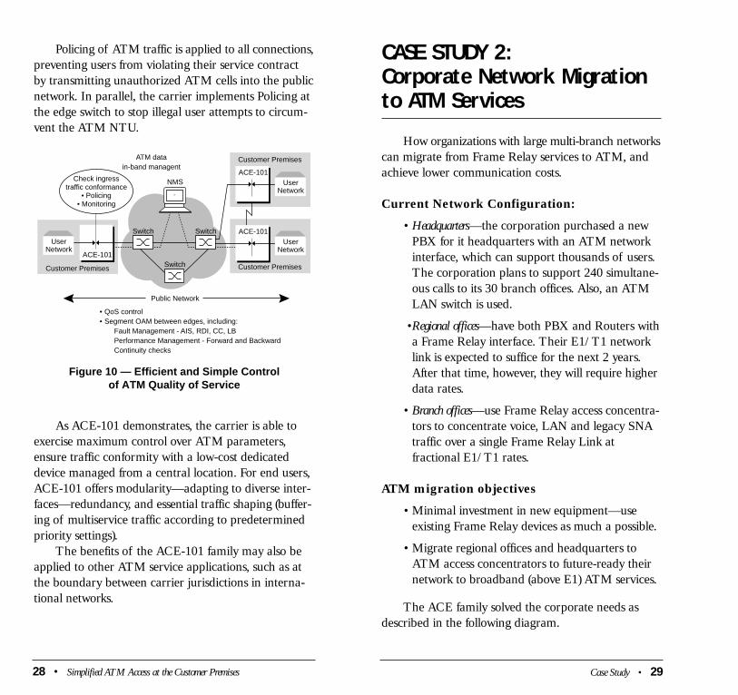
Policing of ATM traffic is applied to all connections,
preventing users from violating their service contract
by transmitting unauthorized ATM cells into the public
network. In parallel, the carrier implements Policing at
the edge switch to stop illegal user attempts to circum-
vent the ATM NTU.
As ACE-101 demonstrates, the carrier is able to
exercise maximum control over ATM parameters,
ensure traffic conformity with a low-cost dedicated
device managed from a central location. For end users,
ACE-101 offers modularity—adapting to diverse inter-
faces—redundancy, and essential traffic shaping (buffer-
ing of multiservice traffic according to predetermined
priority settings).
The benefits of the ACE-101 family may also be
applied to other ATM service applications, such as at
the boundary between carrier jurisdictions in interna-
tional networks.
Figure 10 — Efficient and Simple Controlof ATM Quality of Service
Switch
NMS
Public Network
• QoS control• Segment OAM between edges, including:
Fault Management - AIS, RDI, CC, LBPerformance Management - Forward and BackwardContinuity checks
SwitchSwitch
Customer Premises
ACE-101
Customer Premises
ACE-101
Customer PremisesATM datain-band managent
ACE-101User
Network
UserNetwork
Check ingresstraffic conformance
• Policing• Monitoring
UserNetwork
28 • Simplified ATM Access at the Customer Premises
CASE STUDY 2:Corporate Network Migrationto ATM Services
How organizations with large multi-branch networks
can migrate from Frame Relay services to ATM, and
achieve lower communication costs.
Current Network Configuration:
• Headquarters—the corporation purchased a new
PBX for it headquarters with an ATM network
interface, which can support thousands of users.
The corporation plans to support 240 simultane-
ous calls to its 30 branch offices. Also, an ATM
LAN switch is used.
•Regional offices—have both PBX and Routers with
a Frame Relay interface. Their E1/T1 network
link is expected to suffice for the next 2 years.
After that time, however, they will require higher
data rates.
• Branch offices—use Frame Relay access concentra-
tors to concentrate voice, LAN and legacy SNA
traffic over a single Frame Relay Link at
fractional E1/T1 rates.
ATM migration objectives
• Minimal investment in new equipment—use
existing Frame Relay devices as much a possible.
• Migrate regional offices and headquarters to
ATM access concentrators to future-ready their
network to broadband (above E1) ATM services.
The ACE family solved the corporate needs as
described in the following diagram.
Case Study • 29

ACE-2005, a large modular ATM access concen-
trator (AAC), was used to concentrate eight E1 ports
from the PBX with the E3 ATM port from the LAN
switch over 155 Mbps ATM link.
Each Regional office installed an ACE-20, low-end
low-cost access concentrator, which provided an E1
PBX interface and E1 or V.35 Frame Relay interface
to the router. As bandwidth requirements increase, the
ACE-20 can later scale up to the ACE-200, which
supports multiple E1 PBX interfaces and multiple
Ethernet or Frame Relay ports as well as higher ATM
rates (up to 155Mbps).
ACE-2 preserved the existing investment in Frame
Relay equipment. This simple low-cost Frame Relay
to ATM converter supports both network and service
interworking, converting the Frame Relay traffic to
ATM cells.
As this study shows the ACE family can offer a
simple low-cost migration to ATM giving organizations
the flexibility to use existing equipment or migrate to
ATM-based equipment as bandwidth requirements
grow.
Figure 11 — Corporate WAN Migration to ATM
ATM
ACE-20
ACE-2
n x 64 / E1
PBX Router
Regional Branch Office
Frame RelayE1
PBX
ACE-2005
LAN Switch
Headquarters
E3 8 x E1
155 Mbps
FRAD
PBX Router
Branch Office
Frame RelayE1
E1
30 • Simplified ATM Access at the Customer Premises Glossary • 31
Glossary
Bridge—A device that connects and passes packets
between two network segments. Bridges operate at
Layer 2 of the OSI reference model (the data-link
layer) and are insensitive to upper-layer protocols. A
bridge will examine all frames arriving on its ports and
will filter, forward, or flood a frame depending on the
frame’s Layer 2 destination address.
Cell—For ATM, most vendors have agreed that this
information “package” will be developed consisting of
53 bytes or “octets”. Of these, the first 5 constitute the
header; 48 carry the payload
Cell Delay Variation (CDV)—ATM performance
parameter which specifies the potential variation (+/-)
from the expected average transit delay through the
network over a given virtual circuit.
Cell Error Ratio (CER)—ATM performance para-
meter which specifies the ratio of errored cells to the
total cells transmitted over a given virtual circuit.
Cell Loss Priority (CLP)—A 1-bit field in an ATM
cell header that provides a two level priority indicator.
Used to bias the discarding of cells toward lower prior-
ity cells in the event of congestion. Similar to the DE
bit in frame relay.
Cell Loss Ratio (CLR)—ATM performance para-
meter which specifies the ratio of lost (non-delivered)
cells to the total cells transmitted over a given virtual
circuit.
Cell Transfer Delay (CTD)—ATM performance
parameter which specifies the average transit delay of
cells between a source and destination over a given
virtual circuit.
Central Office (CO)—(1) A local telephone company
office which connects to all local loops in a given area
and where circuit switching of customer lines occurs.
(2) A local Telephone Company switching system,
where Telephone Exchange Service customer station
loops are terminated for purposes of interconnection
to each other and to trunks. In the case of a Remote
Switching Module (RSM), the term Central Office
designates the combination of the Remote Switching
Unit and its Host.
Channel Service Unit/Data Service Unit
(CSU/DSU)—A digital interface unit that connects
end user equipment to the local digital telephone loop.
Circuit—A two-way communications path. (2) A
communication path or network; usually a pair of
channels providing bidirectional communication.
Circuit Emulation—A connection over a virtual
circuit-based network providing service to the end users
that is indistinguishable from a real, point-to-point,
fixed-bandwidth circuit.
Committed Burst (Bc)—Amount of data allowed
in time T=Bc/CIR without being marked DE.
Concentrator—Device that serves as a wiring hub
in star-topology network. Sometimes refers to a device
containing multiple modules of network equipment.
Congestion—Excessive network traffic.
Congestion control—Network management issue
for the controlling of traffic flow so switches and end-
stations are not overwhelmed with information and
cells subsequently dropped.
Constant Bit Rate (CBR)—Delay intensive applica-
tions, such as video and voice, that must be digitized
and represented by a continuous bit stream. CBR
traffic requires guaranteed levels of service and
throughput.
32 • Simplified ATM Access at the Customer Premises
Data Exchange Interface (DXI)—(1) ATM: A
variable-length frame-based ATM interface between
a DTE and a special ATM DSU/CSU. The ATM
DSU/CSU converts between the variable-length DXI
frames and the fixed-length ATM cells. (2) Defines the
format for transmitting information that has gone
through the ATM convergence sublayer.
Data Service Unit—Device on the customer end
of a digital circuit that provides framing of sub-rate
(under 64 Kbps) customer access channel(s) onto
higher rate data circuits. May be combined with a
CSU in a single device.
Digital PBX—A private branch exchange (PBX)
that operates internally on digital signals. Thus, voice
signals must be digitized for use in the PBX.
DSU/CSU—Equipment used to terminate a Switched
56 line and convert a PC’s digital data signal into a
digital transmission signal.
E1—The term for a digital facility used for transmitting
data over a telephone network at 2.048 Mbps. The
European equivalent of T1.
E3—The highest transmission rate generally available
in the European digital infrastructure (34 Mbps).
Edge Switch/Access Router—Device used to take
frames from LANs and send them over an ATM network
as cells. Normally provides LAN emulation and, if
used for PBX connections, circuit emulation.
Excess Burst (Be)—Transient capacity above CIR
in FR net.
Frame—A logical grouping of information sent as a
link-layer unit over a transmission medium. The terms
packet, datagram, segment, and message are also used
to describe logical information groupings at various
layers of the OSI reference model and in various tech-
nology circles.
Glossary • 33

Frame Relay—High-performance interface for
packet-switching networks. Considered more efficient
than X.25 which it is expected to replace. Frame relay
technology can handle “bursty” communications that
have rapidly changing bandwidth requirements.
LAN Emulation—A technique for legacy LAN
MAC-layer protocols like Ethernet and token ring, to
work transparently across an ATM network.
LAN Emulation Client (LEC)—ATM Forum-
defined specifications in support of LAN-to-LAN
connectivity, called LAN Emulation. LEC defines that
set of functions implemented in an ATM network that
provide LAN DTEs with information regarding the
location of the other LAN Emulation services.
Local Area Network (LAN)—(1) A network cover-
ing a relatively small geographic area (usually not
larger than a floor or small building). Compared to
WANs, LANs are usually characterized by relatively
high data rates. (2) Network permitting transmission
and communication between hardware devices, usually
in one building or complex.
Local Loop—The line from a telephone customer’s
premises to the telephone company Central Office.
Multiprotocol encapsulation over ATM—The
process for enabling an ATM device or application to
add a standard protocol identifier to the LAN data
which allows higher-layer protocols, such as IP, to be
routed over ATM.
Network Terminating Equipment (NTE)—A
grouping of ISDN functions at the boundary between
the ISDN and the subscriber.
Postal, Telegraph and Telephone Company
(PTT)—Generic term for a provider of these services.
A governmental agency in many countries.
34 • Simplified ATM Access at the Customer Premises Glossary • 35
Quality Of Service (QOS)—Term for the set of
parameters and their values which determine the
performance of a given virtual circuit.
Router—(1) An OSI Layer 3 device that can decide
which of several paths network traffic will follow based
on some optimality metric. Also called a gateway
(although this definition of gateway is becoming
increasingly outdated), routers forward packets from
one network to another based on network-layer infor-
mation. (2) A dedicated computer hardware and/or
software package which manages the connection
between two or more networks.
Routing—The process of finding a path to the desti-
nation host. Routing is very complex in large networks
because of the many potential intermediate destinations
a packet might traverse before reaching its destination
host.
Switch—In the context of Frame or LAN switching,
this refers to a device which filters, forwards and floods
frames based on the frames destination address. The
switch learns the addresses associated with each switch
port and builds tables based on this information to be
used for the switching decision. Some switches are high
speed implementations of bridges where switching
decisions are made in silicon, usually an Application
Specific Integrated Circuit (ASIC).
Switched Virtual Circuit (SVC)—A virtual link,
with variable end-points, established through an ATM
network. With an SVC, the user defines the end-points
when the call is initiated that are subsequently termi-
nated at the end of the call. With a PVC, the end-
points are predefined by the network manager. A single
virtual path may support multiple SVCs.
T1—(1) Digital transmission facility operating with a
nominal bandwidth of 1.544 Mbps. Also known as
Digital Signal Level 1 (D1). Composed of 24 DS-0

36 • Simplified ATM Access at the Customer Premises
Virtual Path Connection (VPC)—Virtual paths
in two or more sequential physical circuits can be
concatenated to create a logical connection, called a
VPC. VPCs must be pre-configured. All cells traversing
VCs in a VPC are routed the same way.
Virtual Path Identifier/Virtual Channel
Identifier (VPI/VCI)—Combined, these fields
identify a connection in the ATM network.
Glossary • 37
channels in many cases. The T1 digital transmission
system is the primary digital communication system in
North America. (2) A high-speed 1.5 mbits/sec leased
line often used by companies for access to the Internet.
Traffic Shaping—Allows the sending station to
specify the priority and throughput of information
going into the ATM network and subsequently monitor
information progress to meet required service levels.
Undefined Bit Rate (UBR)—Traffic class defined
by the ATM Forum.
Unshielded Twisted Pair (UTP)—Four-pair wire
medium used in the transmission of many different
protocols such as Ethernet, 10BaseT, and CDDI.
User Parameter Control (UPC)—Traffic policing
to ensure that the defined peak traffic rate is not
exceeded in the ATM switch.
Variable Bit Rate (VBR)—Applications which
produce traffic of varying bit rates, like common LAN
applications, which produce varying throughput rates.
Virtual Channel—A defined route between two end
nodes that may access multiple virtual paths.
Virtual Channel Connection (VCC)—Virtual
channels in two or more sequential physical circuits can
be concatenated to create an end-to-end connection,
called a VCC. A VCC is a specific instance of a SVC
or PVC. A VCC may traverse one end-to-end VPC or
several sequential VPCs.
Virtual Channel Identifier (VCI)—The 16-bit
number in an ATM cell header identifying the specific
virtual channel on which the cell is traversing on the
current physical circuit.
Virtual Path—A group of virtual channels, which
can support multiple virtual circuits.

38 • Simplified ATM Access at the Customer Premises Notes • 39
NOTES NOTES

Visit ATG’s Web Site
to read, download, and print
all the Technology Guides
in this series.
www.techguide.com
“The significant problems we face cannot be solved
by the same level of thinking that created them.”
Albert Einstein
www.rad.com
U.S. Headquarters International HeadquartersTel: (201) 529-1100 Tel: 972-3-6458181Fax: (201) 529-5777 Fax: 972-3-6498250
email: [email protected]
PABX
ACE-2005
FR/ATM Device
PABX
ACE-20
E1/T1 E1/T1
E1/T1, E3/T3, STM-1, OC-3C
E3/T3, STM-1, STS-3C
E1/T1, E3/T3, STM-1, STS-3C
FR/ATM Device
PABX
ACE-200 ACE-2 ACE-101
ATMTransport
Frame RelayATM/DXI
ATMBackbone
ACE Family of ATM Access ProductsThe ACE family of ATM Network Termination Units(NTUs) and Interworking Access Devices offers real benefits to carriers and their ATM customers:
• Improved service quality—protecting users fromeach other
• Reduced maintenance costs through fewer service calls
• Better diagnostics
• Greater service flexibility
• Faster deployment of native ATM services
The ACE family includes:
• ACE-101 ATM Network Termination Unit
• ACE-2 ATM Single Service Interworking NTU
• ACE-200 ATM LAN and Voice Interworking NTU
• ACE-20 ATM Triple Service Interworking NTU
• ACE-2005 ATM Multiple Service Inteworking AccessConcentrator
Produced and Published by
One Apple Hill, Suite 216, Natick, MA 01760
Tel: (508) 651-1155 Fax: (508) 651-1171 E-mail: [email protected]
http://www.techguide.com
This Technology Guide is one
of a series of guides, published
by ATG, designed to put complex
communications and networking
technology concepts into practical
and understandable terms.
Each guide provides objective,
non-biased information to assist in
the internal education, evaluation
and decision making process.
This Technology Guide, as well
as the other Communications and
Networking Technology Guides
in the series, are available
on ATG‘s Web Site.


