TECHNICAL GUIDE TOUGH GUN™ Automatic Air-Cooled MIG Guns 500 amp & 600 amp TOUGH GUN™ Automatic Water-Cooled MIG Guns 450 amp & 600 amp SAFETY & WARRANTY INFORMATION INSTALLATION MAINTENANCE GUIDE TECHNICAL DATA OPTIONS EXPLODED VIEW & PARTS LIST TROUBLESHOOTING ORDERING INFORMATION Certified ISO 9001 : 2008 Please read instructions prior to use. Save this manual for future reference. Air-Cooled Water Cooled Water-Cooled Effective September 2010 – QUICK LOAD™ Liners Standard on all TOUGH GUN™ Robotic Air-Cooled MIG Guns
Transcript
TECHNICAL GUIDE
TOUGH GUN™ Automatic
Air-Cooled MIG Guns
500 amp & 600 amp
TOUGH GUN™ Automatic
Water-Cooled MIG Guns
450 amp & 600 amp
SAFETY & WARRANTY INFORMATION
INSTALLATION
MAINTENANCE GUIDE
TECHNICAL DATA
OPTIONS
EXPLODED VIEW & PARTS LIST
TROUBLESHOOTING
ORDERING INFORMATION
Certified ISO 9001 : 2008 Please read instructions prior to use. Save this manual for future reference.
GENERAL SAFETY ........................................................................................................................................ 3
4.1 DIRECT PLUG-INS .......................................................................................................................................... 12
…for selecting a Tregaskiss™ TOUGH GUN™ MIG Gun. Manufacturing operations demand extremely dependable robotic equipment. As the name implies, the TOUGH GUN MIG Gun is made from durable materials and components engineered to perform in a rugged welding environment. Your TOUGH GUN MIG Gun is completely assembled and ready to weld, and has undergone numerous quality checks to ensure high performance. The instructions and illustrations in this Technical Guide make it easy for you to maintain your TOUGH GUN MIG Gun. Please read, understand, and follow all safety procedures. Keep this booklet as a handy reference when ordering complete guns, parts and special options. For technical support and special applications, please call the Tregaskiss Technical Service Department at 1-855-MIGWELD (644-9353) or fax 1-877-737-2111. Our trained technicians are
available between 8:00 a.m. and 5:00 p.m. EST, and will answer your application or repair questions. Please contact us immediately if you experience any safety or operating problems.
3
WARRANTY
Product is warranted to be free from defects in material and workmanship for the period specified below after the sale by an authorized Buyer. Should there be a defect please refer to our Return Merchandise Policy.
PRODUCT WARRANTY PERIOD
TOUGH GUN™ Robotic MIG Guns and Components 180 days
Low-Stress Robotic Unicables (LSR Unicables) 2 years
Tregaskiss reserves the right to repair, replace or refund the purchase price of non-conforming product. Product found not defective will be returned to the Buyer after notification by Customer Service. Tregaskiss makes no other warranty of any kind, expressed or implied, including, but not limited to the warranties of merchantability or fitness for any purpose. Tregaskiss shall not be liable under any circumstances to Buyer, or to any person who shall purchase from Buyer, for damages of any kind, including, but not limited to any, direct, indirect incidental or consequential damages or loss of production or loss of profits resulting from any cause whatsoever, including, but not limited to, any delay, act, error or omission of Tregaskiss. Genuine Tregaskiss™ parts must be used for safety and performance reasons or the warranty becomes invalid. Warranty shall not apply if accident, abuse, or misuse damages a product, or if a product is modified in any way except by authorized Tregaskiss personnel.
GENERAL SAFETY
Before installation or operation of TOUGH GUN MIG Guns, please read the safety precautions listed below. 1. Do not touch live electrical parts. The following should be checked to prevent electrical shock.
a. Faulty or damaged equipment is repaired or replaced. b. Equipment is off when not in use.
2. Ensure that all safety devices, guards, shields or barriers are properly in place and connected correctly before allowing operation of the equipment.
3. CSA Standard W117.2 CODE FOR SAFETY IN WELDING AND CUTTING obtainable from the Canadian Standards Association, Standards Sales, 178 Rexdale Boulevard, Rexdale, Ontario, Canada M9W 1R3.
4. ANSI Standard Z49.1 CODE FOR SAFETY IN WELDING AND CUTTING obtainable from the American National Standards Institute, 1430 Broadway, New York, NY 10018.
CALIFORNIA PROPOSITION 65 WARNING
This product, when used for welding or cutting, produces fumes or gases which contain chemicals known to the State of California to cause birth defects and, in some cases, cancer. This product contains chemicals, including lead, known to the State of California to cause cancer, and birth defects or other reproductive harm. Wash hands after use.
(California Health & Safety Code Section 25249.5 at seq.)
4
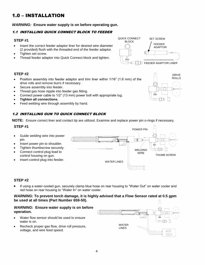
1.0 – INSTALLATION
WARNING: Ensure water supply is on before operating gun.
1.1 INSTALLING QUICK CONNECT BLOCK TO FEEDER
STEP #1
Insert the correct feeder adaptor liner for desired wire diameter (2 provided) flush with the threaded end of the feeder adaptor.
Tighten set screw.
Thread feeder adaptor into Quick Connect block and tighten.
STEP #2
Position assembly into feeder adaptor and trim liner within 1/16” (1.6 mm) of the drive rolls and remove burrs if necessary.
Secure assembly into feeder.
Thread gas hose nipple into feeder gas fitting.
Connect power cable to 1/2” (13 mm) power bolt with appropriate lug.
Tighten all connections.
Feed welding wire through assembly by hand.
1.2 INSTALLING GUN TO QUICK CONNECT BLOCK
NOTE: Ensure correct liner and contact tip are utilized. Examine and replace power pin o-rings if necessary.
STEP #1
Guide welding wire into power pin.
Insert power pin to shoulder.
Tighten thumbscrew securely.
Connect control plug lead to control housing on gun.
Insert control plug into feeder.
STEP #2
If using a water-cooled gun, securely clamp blue hose on rear housing to “Water Out” on water cooler and red hose on rear housing to “Water In” on water cooler.
WARNING: To prevent torch damage, it is highly advised that a Flow Sensor rated at 0.5 gpm be used at all times (Part Number 659-50).
WARNING: Ensure water supply is on before operation.
Water flow sensor should be used to ensure water is on.
Recheck proper gas flow, drive roll pressure, voltage, and wire feed speed.
WATER LINES
THUMB SCREW
POWER PIN
WELDING WIRE
WATER LINES
DRIVE ROLLS
SET SCREW
FEEDER ADAPTOR
QUICK CONNECT BLOCK
FEEDER ADAPTOR LINER
5
1.3 INSTALLING TOUGH GUN™ MIG GUNS EQUIPPED WITH “DIRECT PLUG-INS”
IMPORTANT: The thread-in two-piece power pin incorporates a taper to seat and lock in the power pin to the rear handle block. Make sure power pin is tightened in the block with a wrench to insure pin is secure and will not come loose.
NOTE: The rear handle and screws do not have to be removed when installing the two-piece power pins.
Thread power pin into the rear handle block.
Tighten the power pin into the rear block using a 1” (25 mm) wrench on the rear block and a 5/8” (16 mm) or 3/4” (19 mm) wrench on the power pin.
Install liner (See Section 2.5 LINER REPLACEMENT).
Install gun to feeder (See below).
Miller, Tweco #4 and #5, Lincoln and
Hobart Power Pin
- Insert power pin to shoulder and secure. - Insert control plug to control housing of gun. - Insert control plug into feeder. - Feed welding wire into power pin by hand and tighten drive rolls. - On Lincoln it is necessary to connect gas hose to barbed fitting on power pin.
Bernard™ Style and Euro-Connector - Feed welding wire through female adaptor by hand and tighten drive rolls. - Guide welding wire into connector on gun, carefully insert connector into female adaptor and tighten Euro hand nut or Bernard style locking collar.
ESAB Power Pin (Non Euro Style) - Insert power pin to shoulder and secure. - Feed welding wire into power pin by hand and tighten.
2.0 – MAINTENANCE
2.1 NOZZLE AND CONTACT TIP SYSTEMS – AIR-COOLED GUNS
IMPORTANT:
Neck insulator must be in place before welding to maintain insulation of neck armor. Be sure all parts are tightened well before welding. Replace nozzle retainer with deep counter bore toward the neck. Tighten until retainer and shock washer
are secure.
REMOVAL AND REPLACEMENT
Pull slip-on nozzles off with a clockwise twisting motion.
When installing nozzle, exposed insulator should nest inside shock washer to assure concentricity.
Neck insulators are positioned on the end of the neck with the large insulated counter bore facing the nozzle.
THREAD-ON (OPTIONAL)
Thread-on nozzle system does not require nozzle retainer and cannot be used with heavy duty head.
Neck insulator must be in place. External neck thread can be cleaned with a 9/16” - 18 die.
NOTE: Any of the above nozzle and contact tip systems can be used on the TOUGH GUN 350, 450, 550 or 650 amp models.
NECK INSULATOR
STANDARD DUTY NOZZLE (VARIOUS SIZES AVAILABLE)
HEAVY DUTY TOUGH LOCK CONTACT TIP
HEAVY DUTY TOUGH LOCK
RETAINING HEAD
HEAVY DUTY NOZZLE (VARIOUS SIZES
AVAILABLE)
STANDARD DUTY TOUGH LOCK CONTACT TIP
STANDARD DUTY TOUGH LOCK
RETAINING HEAD
NECK INSULATOR
6
2.2 NOZZLE AND CONTACT TIP SYSTEMS – WATER-COOLED GUNS
IMPORTANT
Neck insulator must be in place before welding to maintain insulation of neck armor.
Be sure all parts are tightened well before welding.
When using the heavy duty retaining head make sure it is tightened with a 5/8” (16 mm) wrench to prevent overheating of contact tip.
To prevent scoring on heavy duty retaining head do not use pliers.
REMOVAL AND REPLACEMENT
Pull slip-on nozzles off with a clockwise twisting motion.
When installing nozzle, exposed insulator should nest inside shock washer to assure concentricity.
Neck insulators are positioned on the end of the neck with the large insulated counter bore facing the nozzle.
Replace nozzle retainer with deep counter bore toward the neck. Tighten until retainer and shock washer are secure.
2.3 NECK REPLACEMENT – AIR-COOLED GUNS
STEP #1
Place neck in vise.
Remove all four housing mounting screws with 3 mm (3/32”) Allen wrench.
Slide handle back exposing connector cone and crimp ring.
Loosen connector cone from neck using a 25 mm (1") wrench.
Remove from vise and thread out neck by hand.
Cable connection between cone and crimp ring should not be disturbed.
STEP #2
NOTE: The neck body is an integral part of the neck and the handle
screws are metric (MS). New handle screws must be used when replacing the neck.
Thread neck into connector cone (hand-tighten).
Place neck in vise and tighten with 1" (25 mm) wrench to within 1/8" (3.2 mm) spacing between the connector cone and body.
Slide housing forward and align with screw holes and body.
NECK
HOUSING POWER CABLE
M5 FLATHEAD SCREWS
STANDARD DUTY NOZZLE VARIOUS LENGTHS
AVAILABLE
HEAVY DUTY CONTACT TIP
HEAVY DUTY GAS
DIFFUSER
NECK
INSULATOR
TOUGH LOCK CONTACT TIP
TOUGH LOCK DIFFUSER
NOZZLE (THREAD ON)
600 AMP
450 AMP
CERAMIC INSULATOR
NECK 1/8” (3.2 mm)
POWER CABLE
7
2.4 NECK REPLACEMENT – WATER-COOLED GUNS
STEP #1
Remove liner from gun (See Section 2.5 LINER REPLACEMENT).
Remove two front housing screws.
STEP #2
Slide housing back.
Unthread power cable.
Cut off water line and conduit clamp and pull hoses off of barbed fittings.
STEP #3
Slide clamps on water line and conduit.
Thread power cable on and tighten.
Push water line and conduit on all the way to base of fittings and crimp.
2.5 LINER REPLACEMENT
NOTE: For guns equipped with “Direct Plug-Ins”, Bernard, or Euro-connector, the procedure is the same. On Miller style guns, liner is held captive by a guide cap, which must be removed and replaced when changing liner.
STEP #1
NOTE: Ensure power supply is off and gun is removed from feeder before proceeding.
Remove nozzle, tip and gas diffuser.
With gun straightened, unthread retainer and remove.
STEP #2
Feed replacement liner through gun using short strokes to avoid kinking. Twist liner clockwise if necessary.
Using a 10 mm wrench, turn thread-in liner retainer in a clockwise direction and tighten in power pin.
M5 SCREWS
NECK WHITE CONDUIT LINE FRONT HOUSING
WATER LINES (BLUE) AND POWER LINE (RED)
NECK FRONT HOUSING
8
STEP #3
Thread liner into power pin.
Trim conduit liner with 3/4” (19 mm) stick out for Air Cooled (404-20 and 404-3 Retaining Heads) and 1/2” (13 mm) for Water Cooled (454-1 Retaining Heads).
Remove any burr that may obstruct wire feed, especially on flat wire type conduit liner.
Replace nozzle, tip and gas diffuser onto neck.
2.6 UNICABLE REPLACEMENT – AIR-COOLED GUNS
STEP #1
Remove liner from gun (See Section 2.5 LINER REPLACEMENT).
Mount neck in vise.
Remove housing screws and slide housing back (front and back).
Loosen connector cone from neck using 1” (25 mm) wrench.
Remove from vise and thread out neck by hand.
Cable connection between cone and crimp ring should not be disturbed.
Unthread power pin and remove using 1 1/4” (32 mm) on connector cone and a 5/8” (16 mm) or 3/4” (19 mm) wrench on power pin. Install new power pin.
Retrieve front and rear housing. Slide housings onto new unicable assembly.
Repeat procedure in reverse to assemble remaining components.
2.7 CABLE BUNDLE REPLACEMENT – WATER-COOLED GUNS
STEP #1
Remove nozzle, tip and retainer.
Take out rear housing screws and remove liner.
NECK CONDUIT LINER
3/4” (19 mm) 1/2" (13 mm)
450/600 AMP
MOUNTING SCREWS
REPLACEMENT UNICABLE
USED UNICABLE
9
STEP #2
Pull the rear handle up the gun approximately 1 ft.
Unscrew power cable from rear power block.
Cut clamps off the water in (blue) line and gas line (white).
Pull gas and water line off of power block.
At this point, rear power block will be removed from gun.
Slide rear handle off gun.
STEP #3
On front of gun, release front handle from neck.
Remove outer jacket by pulling outer jacket only from rear of gun; all that remains are the inner hoses attached to the neck.
STEP #4
Cut clamps off the water (blue) and gas line (white).
Unscrew power cable from neck.
Remove old cable bundle.
STEP #5
Slide rear handle and front housing on to new cable bundle.
Thread power cable (red) on to neck.
Clamp water line (blue) and gas line (white) onto neck.
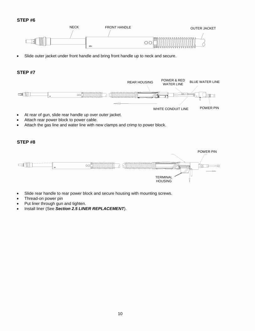
2 PIECE POWER PIN
REAR HANDLE
WHITE CONDUIT LINE
BLUE WATER LINE POWER & RED WATER LINE
450/600 AMP
450/600 AMP NECK
WHITE CONDUIT LINE
FRONT HOUSING
WATER LINES (RED & BLUE) & POWER LINE
OUTER JACKET
NECK
WHITE CONDUIT LINE
BLUE WATER LINE
USED RED WATER LINE & POWER LINE
FRONT HOUSING NECK
NEW CABLE BUNDLE
10
STEP #6
Slide outer jacket under front handle and bring front handle up to neck and secure.
STEP #7
At rear of gun, slide rear handle up over outer jacket.
Attach rear power block to power cable.
Attach the gas line and water line with new clamps and crimp to power block.
STEP #8
Slide rear handle to rear power block and secure housing with mounting screws.
Thread-on power pin
Put liner through gun and tighten.
Install liner (See Section 2.5 LINER REPLACEMENT).
6 452-1 NECK INSULATOR - USE WITH 454-1 HEAD 452-3 NECK INSULATOR - USE WITH 404-20 HEAD
7 INTERNAL WATER LINE (C/W (2) 656-1 CLAMPS) 656-15 656-15 15’ SERVICE
8 657-15 657-15 CONDUIT 15’ 658 658 RED WATER LINE - OUT (C/W (1) 656-1 CLAMP) 658-1 658-1 BLUE WATER LINE - IN (C/W (1) 656-1 CLAMP)
(LOCATED AT QUICK CONNECT POWER BLOCK ASSEMBLY)
9 POWER CABLE ASSEMBLY
659-10 659-10 10’ SERVICE (ACTUAL LENGTH - 9.5’) 659-12 659-12 12’ SERVICE (ACTUAL LENGTH - 11.5’) 659-15 659-15 15’ SERVICE (ACTUAL LENGTH - 14.5’)
10 CABLE BUNDLE (COMPLETE WITH CLAMPS)
661-10 661-10 10’ SERVICE (OUTER JACKET ONLY 663-1-10) 661-12 661-12 12’ SERVICE (OUTER JACKET ONLY 663-1-12) 661-15 661-15 15’ SERVICE (OUTER JACKET ONLY 663-1-15)
11 660-10 660-10 HOUSING FRONT
12 416-15 416-15 HOUSING
13 664-400 664-400 POWER PIN BLOCK
PART # DESCRIPTION 450 amp 600 amp
14 214 214 TWECO® #4
214-2 214-2 LINCOLN®
214-4 214-4 L-TEC MT SERIES® 214-6-116 214-6-116 MILLER® 1/16 214-6-332 214-6-332 MILLER® 3/32 214-7 214-7 LINCOLN® SHORT 214-12 214-12 TWECO® #5 214-13 214-13 PANASONIC® 214-14 214-14 PANASONIC® SHORT 414-1 414-1 O-RING 414-2 414-2 LINER SET SCREW 414-11-2 414-11-2 O-RING FOR MILLER® POWER PIN
15 QUICK LOAD™ LINERS
415-26 415-26 LINER RETAINER (LINER DOES NOT COME WITH RETAINER)
415-35-6Q 415-35-6Q FOR .035" - .045" (0.9 - 1.2 mm) WIRE - 6' (1.8 m)
415-35-10Q 415-35-10Q FOR .035" - .045" (0.9 - 1.2 mm) WIRE - 10' (3 m)
415-35-15Q 415-35-15Q FOR .035" - .045" (0.9 - 1.2 mm) WIRE - 15' (5 m)
415-35-25Q 415-35-25Q FOR .035" - .045" (0.9 - 1.2 mm) WIRE - 25' (8 m)