20
T T e e c c h h C C u u t t 4 4 ™ ™ Precision Low-Speed Saw Operation Manual 2376 E. Pacifica Place * Rancho Dominguez, CA 90220 * 310-635-2466 www.alliedhightech.com 01/11, Version 2.2

TTeecchhCCuutt 44™™ Precision Low-Speed Saw
Operation Manual
2376 E. Pacifica Place * Rancho Dominguez, CA 90220 * 310-635-2466 www.alliedhightech.com
01/11, Version 2.2

2
Table of Contents Warning/Safety Precautions 3 Machine Details 4 Warranty 5-6 Installation, Electrical and Mechanical 7 Operation/Definition of Keypad Buttons 8 Arm Position/Micrometer Head 9 Blade Installation/Coolant/Sample Screen 10 Splash Shield/Fixture Installation 11 Setting Cut Depth 12 Dressing Stick, Definition/Operation 13 Maintenance 14 Wiring Diagrams, 115 V & 230 V 15-16 Faceplate Diagram 17 Spare Parts List 17 Blade Recommendations 18

3
Safety Precaution Sheet
WARNING!!
Please read carefully before operating the machine.
1. All operators should be thoroughly trained in all aspects of the operation of this machine
prior to use following the guidelines set forth in this manual.
2. The machine should be placed on a safe, sturdy, suitable surface to allow for operation without hindrance to the controls.
3. Only consumables that are compatible with the operation of a sectioning saw should be
used.
4. Any local machinery and occupational standards must be strictly observed.
5. The operator must ensure the piece being sectioned is held properly and securely in the fixture prior to saw operation.
6. The operator should not be wearing any loose clothing, ties or jewelry that can get
caught in the machine during operation.
7. At all times, proper safety precautions should be observed to prevent injuries, particularly to eyes and extremities.
Note: If the machine is subjected to misuse, neglect, incorrect installation, unapproved alterations, incorrect feed voltage, accidental damage or unauthorized/improper repair, the warranty will become void and the user will be liable for damage(s) to the machine or injuries to the user.
Safety Labels
Electrical This sticker is located on the rear of the machine and indicates where the power cord is connected to the machine to make it operational. Remove the power cord when changing fuses or when performing any service. Hand Entanglement It is possible to entangle your hands or fingers in the moving parts of this machine. Please use caution and turn off all power when reaching into the machine. Protective Eyewear Recommended It is recommended that protective eyewear be worn during operation.

4
Machine Details
Model: TechCut 4™ Item No.: #5-5000, #5-5000-230 Description: Low Speed Saw Serial Number: __________________ Voltage: 115 V AC (50/60 Hz) ____________
OR 230 V AC (50/60 Hz) ____________
Power: 1/17 HP (45 W) Fuse: 5 A Slow Blow, 5 x 20 mm, 250 V Date of Mfr: _________________ mm/dd/yyyy Dimensions: 11" (280 mm) W x 17" (432 mm) D x 14" (355 mm) H
Weight: 38 lb. (17 kg) Shipping Dimensions: 24" (610 mm) x 34" (864 mm) x 21" (533 mm)
Shipping Weight: 50 lb. (22.7 kg) Recommended Operational Temperature Range: 50° F (10° C) – 80° F (26° C) Humidity Range: None Established Note: The TechCut 4™ is designed to operate at either 50 Hz or 60 Hz frequency.

5
Warranty Thank you for choosing Allied High Tech! This product is warranted by Allied High Tech Products, Inc., to be free of defects in material and workmanship for two (2) years from date of original purchase. This warranty does not cover damage from abuse, neglect, negligence, accidental breakage, improper use or failure to exercise reasonable care and maintenance in accordance with the instructions accompanying this product. To obtain warranty support or spare parts please contact your Product Application Specialist or Allied Technical Support at (310) 635-2466, M-F, 8:00 – 5:00 PM PST. Please be prepared to supply the serial number for the product you are calling about; this will help our staff confirm warranty eligibility and provide you with thorough, timely assistance. At your discretion, in consultation with your Allied Product Application Specialist or an Allied Technical Services representative, we will be happy to send you replacement parts, at no charge - or - have you send the product to Allied for warranty repair. Most Allied products are designed for ease of parts replacement, so customer repairs, with no-charge parts from Allied, are often the quickest and easiest way to return a product to active service. If you wish to return a product to Allied for warranty repair, you must first obtain an “REA”, or “Return Equipment Authorization” number. An REA may be obtained from your Product Application Specialist, or from a member of our Technical Services staff. Please ensure that your REA number is referenced prominently on your shipping paperwork as outlined below. Please pre-pay shipping “to” Allied and provide an address and phone number for return shipping, which is paid for by Allied during the warranty period. Please return your product to: Allied High Tech Products, Inc. REA#: ___________________ 2376 East Pacifica Place Rancho Dominguez, CA 90220 USA P: (310) 635-2466 Please Note: Damage to products during transit to/from Allied, or resulting from improper in-bound packaging, will not be the responsibility of Allied. Therefore, please ensure that your product is securely boxed or packaged. It is further recommended that you insure your shipment for the full value of the product. Should damage occur during in-bound shipment, we will be happy to provide you with a formal quotation estimating the cost of materials and labor necessary to repair such damage. A Purchase Order will be required to make these repairs.

6
Repairs for Products No Longer Under Warranty Allied will be happy to make repairs to products no longer under warranty. For these products we will be pleased to provide you with an estimate of the costs (materials and labor) necessary to make requested repairs. For non-warranty repairs, customer is responsible for in-bound (to Allied) and out-bound (from Allied to customer) shipping and handling costs. Non-warranty repairs are made with the same attention to detail and commitment to quality workmanship that is provided to “in” warranty customers. Thank you for choosing Allied and please let us know if you have comments or questions about these warranty provisions.

7
Installation The unit should be placed on a clean, dry surface with the control panel facing the front of the counter/table on which it is placed. Electrical Machines operating on 115 V AC are supplied with an electrical power cord that fits a standard North American outlet. The electrical power cord for all 230 V machines is provided. Since there are so many different 230 V outlet types, it is the responsibility of the end user to supply either a new power cord or install a plug onto the end of the one provided if it does not match. If a power cord other than the one provided is used, be sure to select one properly rated for the machine. Before the electrical power cord is plugged into the wall socket, make sure the power is switched to the “off” position on the power inlet found at the rear of the machine. The power inlet contains a fuse holder that accepts two 5 x 20 mm fuses. See “Machine Details” on page 4 for information on the fuse rating. If any maintenance is done to the machine that requires opening the electrical compartment, the power cord should be disconnected from the machine. RESET FUNCTION: If for any reason the functions of the machine fail to operate (and the fuse has been checked to still be in working condition) and the machine is plugged in, the electronics should be reset. Press and hold both the “up” and “down” arrows on the keypad while powering the machine on from the rear. Continue to hold in the buttons until the display resets and displays “000”. Mechanical The arm on which the fixtures will be attached is shipped uninstalled. Install the arm as shown in Figure 1. Place the arm over the collar of the micrometer head and secure the clamp onto the arm using the two bolts included. Once secured, turn the micrometer head so the arm travels left-to-right and right-to-left. The micrometer head thimble should turn with ease. If the arm clamp is too tight and the micrometer thimble is difficult to rotate, the screws securing the clamp will need to be loosened.
Figure 1

8
Operation The TechCut 4™ is used to section a variety of materials. Samples to be sectioned are secured to a fixture appropriate to the shape and material type. The fixture is attached to a hinged arm that directs the travel of the sample into the blade using gravity to provide force throughout the sectioning process. The blade speed is variable from 0 to 500 RPM. The usable blade size range is from 3 to 6 inches in diameter with a ½" arbor. Please note the TechCut 4™ model 5-5100, with a raised blade spindle, can only use 5 to 6 inch blades with proper contact with the coolant. The arm position, which dictates where on the sample the blade will actually cut, is controlled with a micrometer with a resolution of 1 micron (µ). The micrometer is rotated to position the sample horizontally, left-to-right-to-left, so the blade will cut the sample at the desired point. Cut depth can be controlled using the adjustable slider on the arm. Weights on the arm provide additional force to the sample, if needed. A coolant reservoir stores and provides coolant to the blade. The coolant lubricates the contact between the sample and the blade to maximize life and efficiency of the blade and minimize thermal damage. The dressing stick attachment is used to clean (dress) a blade by removing debris or gummed material that would otherwise hinder contact between the blade and the sample, slowing the cut.
Adjusting Blade Speed - Using the arrow buttons, blade speed may be adjusted up or down. Press once and release to adjust the speed in increments of 10 RPM. Press and hold the arrow button to rapidly scroll to a different speed.
Starting the Blade - With a speed value selected and the machine in “stop” mode (indicated with the LED in the stop button being illuminated) pressing the start button activates blade rotation. During operation, if the limit sensor is activated the machine
will cease operation and the display will read “ 0 “. Operation will only resume once the sensor is deactivated, by repositioning whatever is activating it, like the arm or stop slider.
Stopping Operation - During operation, pressing the stop button will cease all functions including blade rotation and sample rotation (if activated).
Rotation - The rotation button activates the rotation attachment. With the button pressed and held, the speed of rotation may be adjusted using the up and down arrow buttons. Once established, the value is locked into memory until it is changed or the machine is unplugged.

9
Arm Position and Micrometer Head The arm is used to direct the sample into the blade and keep it from wandering during the cutting action. Once the sample is secured into the appropriate fixture and secured to the arm, the position of cut must be established. By rotating the micrometer, position the sample so the arm can lower it next to the blade to determine cut depth. Lower it to a point at which the blade will either pass through the sample completely or to the point where it needs to stop. Once there, adjust the slide stop by loosening the screw and lowering it until it makes contact with the arm stop. When it makes contact, the display should read “ 0 “ and the screw should be tightened to secure the slide stop in that position. Raise the arm so the sample is lifted above the blade, and rotate the micrometer to position the sample over the blade where the cut is to be made. Once there, start the blade (after selecting the speed) and gently lower the sample onto the blade. NOTE: Starting the blade with a sample resting on it may cause the blade to break. As the blade rotates, the sample will travel into the blade until the slider stop makes contact with the arm stop. At this point, the sensor will deactivate the motor and the blade will no longer spin. Now the arm can be lifted and the fixture removed to gain access to the sample. If further cuts need to be made on the same part, the micrometer may be rotated to reposition the sample. Extended Range The micrometer has an extended range capability that allows the user to position the arm farther from the center panel to increase sample size capacity. At the rear of the machine, there are two set-screws that, when loosened (do not loosen more than one turn), allow the micrometer sleeve to be positioned in or out (see below). Once the arm is in the desired position, tighten the setscrews slightly. Over-tightening will put resistance on the cutting motion of the arm.
Set-screws

10
Installing Blades To install a blade, the sample catch screen must be removed. Loosen and remove the blade-retaining nut by rotating it counterclockwise. If the nut is too tight and the spindle is slippery, the loosening rods may be used to remove the nut. Both this nut and the spindle sleeve have two holes where the loosening rods may be placed for leverage. Once the nut is removed, take off the outer flange and slide the blade over the spindle against the inner flange. Replace the outer flange and secure the nut onto the spindle using only finger pressure. Coolant It is recommended that a water-soluble coolant, such as Allied’s Low Speed Cutting Fluid (item no. 60-20110) be used to lubricate the blade during cutting. Coolant should be added to the reservoir when it is in place under the main cutting platform. NOTE: The reservoir cannot be removed or installed with the blade installed. The amount of coolant needed is dictated by the diameter of blade used. The smaller the blade’s diameter, the higher the coolant level will need to be. Once the selected blade has been installed, pour the coolant into the reservoir until the tip of the blade is submerged. Adding too much coolant could cause excessive splashing. Changing Coolant Generally, when the coolant becomes darker than its original color, it may require replacement. Disposal of the coolant should be done according to local, state and federal laws regarding such products. Consult the product MSDS for information pertaining to the ingredients. The MSDS can also be found at Allied’s website: www.alliedhightech.com Before removing the coolant reservoir, it is necessary to remove the blade. Slide the coolant tray completely out from under the cutting platform until it disengages from the rails on which it slides (see figure 2). Once the coolant has been properly disposed of, wipe down the inside of the tray and wash out any debris or sediment. Fill the tray only after it has been replaced into the machine. Sample Screen The perforated sample screen is designed to catch material that falls from the sample after the cut is made and before it can fall into the coolant reservoir. On the screen are brushes installed to wipe the blade as it travels upward from the coolant reservoir and avert excessive coolant splash.
Figure 2

11
Fixture Screw
Coolant Splash Shield The coolant splash shield helps to keep the operator from getting splashed during normal operation of the saw. It is not intended to prevent eye injury. Eye protection should be worn during operation. Fixtures All fixtures are attached to the TechCut 4™ arm using the universal screw included with the saw (see figure 3). A spare screw is included should the original become lost. Inside the coolant housing, spare dressing sticks, loosening rods and other tools may be kept.
The TechCut 4™ comes with three (3) fixtures: 5-5005, 5-5010 and 5-5020. Item No. 5-5005 is used for securing round stock and mounted samples. Item No. 5-5010 is used to secure round or oval- shaped samples. Item No. 5-5020 is used to secure rod material, flat samples like PCB coupons and other materials. The clamp can be positioned to utilize either the V-side or the flat side and used as a parallel clamp.
Note: All samples should be properly secured into the fixture. Failure to do so may cause blade or sample damage. Blade damage caused by improperly securing the sample into the fixture will void the product warranty for the blade. Weights The two (2) 150-gram stainless steel weights included with the TechCut 4™ slide onto the topside of the arm and are secured into position using the red screws. By placing weights nearer the sample and blade, the force can be increased to the sample. Adding more weight will not necessarily provide a faster cut and may cause damage to the blade or the sample. By positioning the weights away from the blade and sample, a “counterbalance” may be achieved to offset the weight of the sample and the fixture. Counterbalancing is typically used when cutting delicate samples.
Figure 3
12
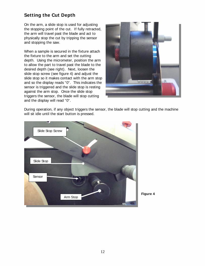
Setting the Cut Depth On the arm, a slide stop is used for adjusting the stopping point of the cut. If fully retracted, the arm will travel past the blade and act to physically stop the cut by tripping the sensor and stopping the saw. When a sample is secured in the fixture attach the fixture to the arm and set the cutting depth. Using the micrometer, position the arm to allow the part to travel past the blade to the desired depth (see right). Next, loosen the slide stop screw (see figure 4) and adjust the slide stop so it makes contact with the arm stop and so the display reads “0“. This indicates the sensor is triggered and the slide stop is resting against the arm stop. Once the slide stop triggers the sensor, the blade will stop cutting and the display will read “0“. During operation, if any object triggers the sensor, the blade will stop cutting and the machine will sit idle until the start button is pressed.
Arm Stop
Sensor
Slide Stop
Slide Stop Screw
Figure 4

13
Dressing Stick The TechCut 4 ™ is equipped with a removable dressing stick mechanism designed for cleaning blades that become “loaded” with the material being cut. The dressing fixture is secured to the end of the arm stop. It is secured into place like a socket wrench, when the ball pin and mounting sleeve click into place (see figure 5). The fixture may be removed by pressing the ball and sliding it off the arm stop. On the fixture, the dressing stick is secured with a screw. A mechanical stop positions the dressing stick so as not to interfere with the movement of the arm (see figure 6).
Dressing the blade can be done in between cutting applications or during the cutting process. During operation, the dressing fixture may be removed to allow easy access to the controls. One or two applications of the dressing stick onto the blade are typically recommended.
Mechanical Stop
Securing Screw
Figure 5
Figure 6

14
Maintenance If cleaned after each use, the TechCut 4™ is designed to provide many years of trouble-free service. There are no maintenance requirements for the motor or electrical components. Fixtures and the arm should be wiped after each use to remove cutting fluids and debris. The indexing micrometer may require periodic oiling. If the micrometer head becomes frozen, it can easily be replaced.

15
TechCut 4™ Wiring Diagram, 115 V AC
16
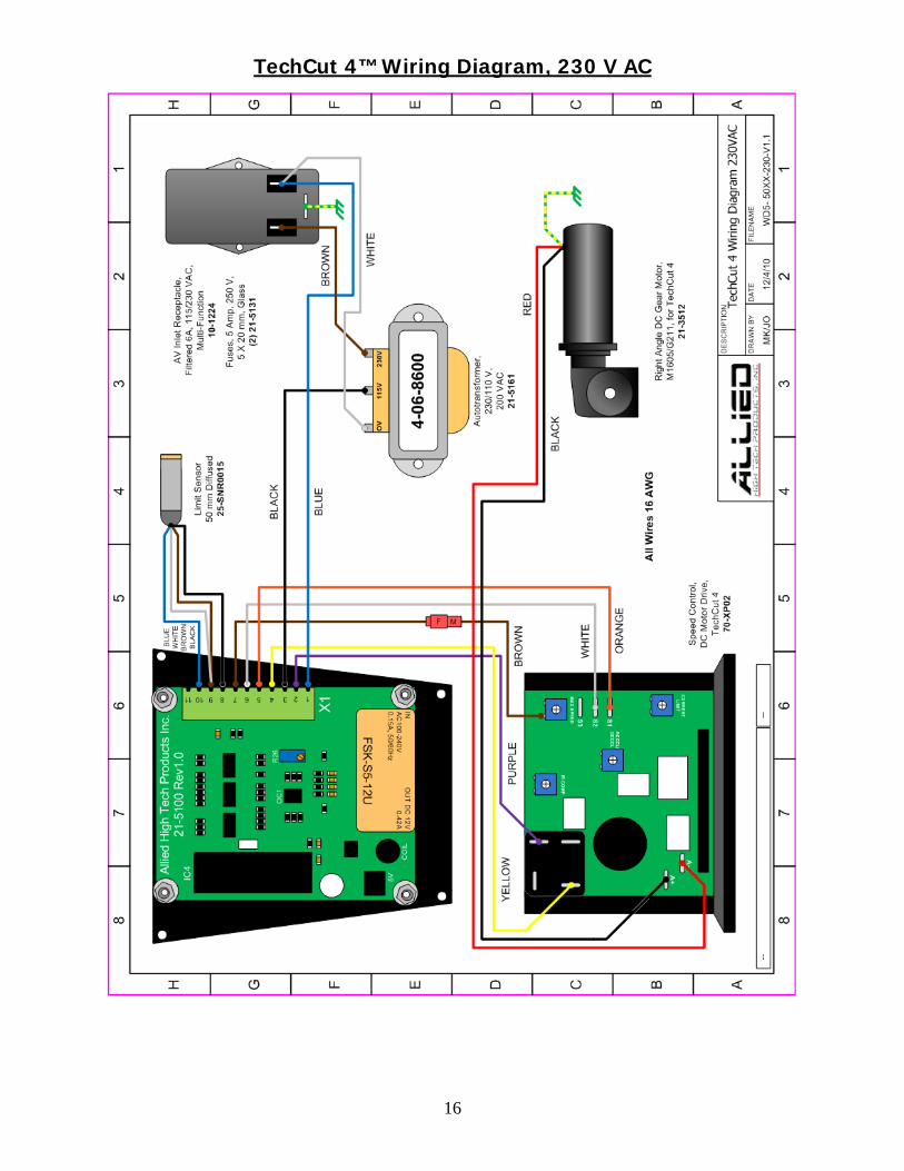
TechCut 4™ Wiring Diagram, 230 V AC

17
Faceplate Diagram Spare Parts List * Spindle Assembly – Bearings are press fit into the bearing housing therefore the entire
spindle, housing and bearings are sold as a single unit, item No. 21-5400 ** Micrometer Head – The micrometer head is pressed into the sleeve and therefore is
sold as an assembly, which includes the sleeve and micrometer head. *** Dressing Stick Attachment – The dressing stick attachment, with the exception of the
dressing stick securing screw (page 13), is sold as a single unit.
TechCut 4™
Control Panel and PCB 21-5100 DC Motor, 1/17 HP 21-5111 Sensor, Auto Shutoff 25-SNR0015 DC Drive, XP-02 70-XP02 AC Inlet Filter 10-1224 Fixture Screw 21-5029 Splash Shield 21-5140 Spindle Assembly 21-5400* Micrometer Head & Sleeve 21-5401** Belt 21-5136 Blade Flange, each 21-5018 Blade Retaining Nut 21-5019 Dressing Stick Attachment 21-5402***

18
Blade Recommendations The following guideline may be used to help determine which blade is right for the specific material being sectioned. MB: Metal Bond RB: Resin Bond D: Diamond CBN: Cubic Boron Nitride HC: High Concentration LC: Low Concentration Blade Material Recommended Speed (RPM) MB, HC, D General cutting: 150 to 300
Titanium Metal matrix composites PCB’s Thermal spray coatings Ceramics MB, LC, D Delicate cutting of: 200 to 400 Ceramics Silicon Glass Microelectronic devices RB, D Delicate materials: 150 to 250 Silicon ICs GaAs Carbides Ceramics Glass, fused silica, quartz CBN Steel and ferrous metals, 100 to 350 (depending on size) Nickel, Cobalt, lead based alloys, superalloys and iron

19
(This page has been left blank intentionally)

20
2376 East Pacifica Place, Rancho Dominguez, CA 90220
(800) 675-1118 (US & Canada) * (310) 615-2466 (Worldwide) * (310) 762-6808 FAX www.alliedhightech.com


