SUPPLY & EXHAUST HEADERS Most often used in subsurface systems. Use Techline CV Blank Tubing if zone is under 5 GPM or PVC/PE pipe if above. Insert Adapter for 1” or Larger PE TLIAPE-B Insert Adapter for 1½” or Larger PVC TLIAPVC-B ½” MPT Adapter TL050MA 6” Soil Staple TLS6 SUBSURFACE LAYOUT LAYOUT TIPS AND RECOMMENDATIONS Techline CV can be installed subsurface buried evenly up to 6”. Use guidelines to select which Techline CV to use and how much to apply properly. LANDSCAPE & TURF TECHLINE CV QUICK INSTALL GUIDE Estimating How Much Techline CV to Use Multiply the square footage of the area x 12, divide that number by the minimum recommended row spacing from the General Guidelines Chart. (See back of sheet for more information.) Fittings • Techline CV fittings are recommended. They are the fastest to install, most economical and do not require clamps at pressures less than 50 psi. • ½” Poly insert fittings with clamps can be used. • 700 Series compression fittings can also be used. Low Volume Control Zone Kit Pre-assembled valve, filter and pressure regulator is more convenient to use than separate valve, filter and pressure regulator. Two Models Available: • Model # LVCZS8010075-LF (0.25 - 4.4 GPM) • Model # LVCZS8010075-HF (4.5 - 17.6 GPM) LOW VOLUME CONTROL ZONE KIT For easy installation of a valve, disc filter and pressure regulator valve (PRV)* use Netafim’s Low Volume Control Zone Kit. Models are available with a pre-assembled with 1” Control Valve, ¾” Disc Filter and High/Low Flow Pressure Regulator. Low Flow (0.25 - 4.4 GPM) LVCZS8010075-LF High Flow (4.5 - 17.6 GPM) LVCZS8010075-HF STAPLES Use one TLS6 staple every 3’ of Techline CV in sand, every 4’ in loam and every 5 ‘ feet in clay. MANUAL FLUSH VALVE Use TLSOV or TLFIG8. Normally placed along exhaust header or at the point farthest away from the control zone kit. Install in the valve box with a gravel sump. Shut-off Valve TLSOV Figure 8 Line End TLFIG8 TECHLINE CV DRIPLINE Start rows of Techline CV 2” from hardscapes and 4” from softscapes. Techline CV Dripline TLCV
Transcript
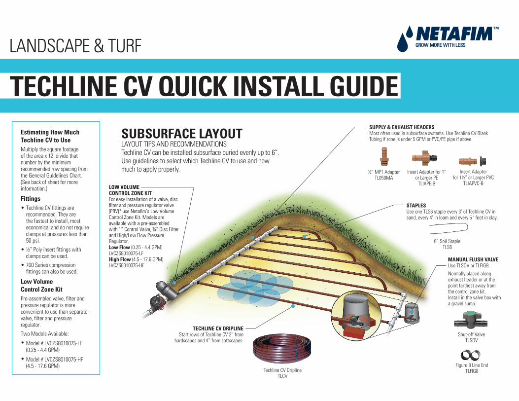
SUPPLY & EXHAUST HEADERSMost often used in subsurface systems. Use Techline CV Blank Tubing if zone is under 5 GPM or PVC/PE pipe if above.
Insert Adapter for 1”or Larger PE
TLIAPE-B
Insert Adapterfor 1½” or Larger PVC
TLIAPVC-B
½” MPT AdapterTL050MA
6” Soil StapleTLS6
SUBSURFACE LAYOUTLAYOUT TIPS AND RECOMMENDATIONSTechline CV can be installed subsurface buried evenly up to 6”. Use guidelines to select which Techline CV to use and how much to apply properly.
LANDSCAPE & TURF
TECHLINE CV QUICK INSTALL GUIDEEstimating How MuchTechline CV to Use Multiply the square footage of the area x 12, divide that number by the minimum recommended row spacing from the General Guidelines Chart. (See back of sheet for more information.)
Fittings• Techline CV fittings are
recommended. They are the fastest to install, most economical and do not require clamps at pressures less than 50 psi.
• ½” Poly insert fittings with clamps can be used.
• 700 Series compression fittings can also be used.
Low VolumeControl Zone Kit
Pre-assembled valve, filter and pressure regulator is more convenient to use than separate valve, filter and pressure regulator.
Two Models Available:
• Model # LVCZS8010075-LF (0.25 - 4.4 GPM)
•
Model # LVCZS8010075-HF
(4.5 - 17.6 GPM)
LOW VOLUMECONTROL ZONE KITFor easy installation of a valve, disc filter and pressure regulator valve (PRV)* use Netafim’s Low Volume Control Zone Kit. Models are available with a pre-assembled with 1” Control Valve, ¾” Disc Filter and High/Low Flow Pressure Regulator.Low Flow (0.25 - 4.4 GPM)LVCZS8010075-LFHigh Flow (4.5 - 17.6 GPM)LVCZS8010075-HF
STAPLESUse one TLS6 staple every 3’ of Techline CV in sand, every 4’ in loam and every 5 ‘ feet in clay.
MANUAL FLUSH VALVEUse TLSOV or TLFIG8.Normally placed along exhaust header or at the point farthest away from the control zone kit.Install in the valve box with a gravel sump.
Shut-off ValveTLSOV
Figure 8 Line EndTLFIG8
TECHLINE CV DRIPLINEStart rows of Techline CV 2” from
hardscapes and 4” from softscapes.
Techline CV DriplineTLCV
To determine the proper Techline CV to use on your project, you will need to know the following:
1. What are you irrigating - shrubs and ground cover or turf areas?2. What type of soil do you have - clay, loam or sand?3. How many square feet are going to be irrigated?
Use this simple formula for calculating approximately how much Techline CV to use in the area.
Multiply the square footage of the area x 12Divide that number by the minimum number of inches apart the rows should be(also called Lateral (Row) spacing)
This number is found in the General Guidelines chart. While this quick formulais not meant to replace an actual design and take-off, you will have a fairlyaccurate idea of how many feet of dripline you will need.
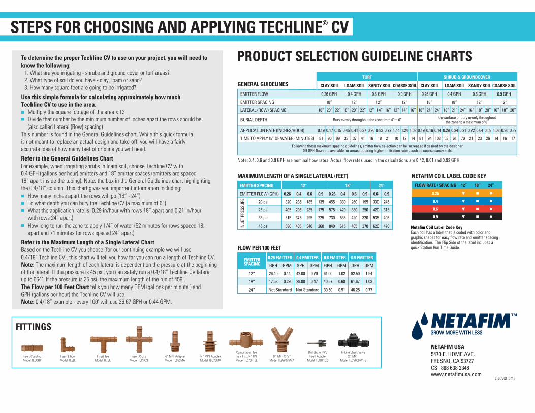
Refer to the General Guidelines ChartFor example, when irrigating shrubs in loam soil, choose Techline CV with0.4 GPH (gallons per hour) emitters and 18” emitter spaces (emitters are spaced18” apart inside the tubing). Note: the box in the General Guidelines chart highlightingthe 0.4/18” column. This chart gives you important information including:
How many inches apart the rows will go (18” - 24”)To what depth you can bury the Techline CV (a maximum of 6”)What the application rate is (0.29 in/hour with rows 18” apart and 0.21 in/hour with rows 24” apart)How long to run the zone to apply 1/4” of water (52 minutes for rows spaced 18:apart and 71 minutes for rows spaced 24” apart)
Refer to the Maximum Length of a Single Lateral ChartBased on the Techline CV you choose (for our continuing example we will use0.4/18” Techline CV), this chart will tell you how far you can run a length of Techline CV.Note: The maximum length of each lateral is dependent on the pressure at the beginningof the lateral. If the pressure is 45 psi, you can safely run a 0.4/18” Techline CV lateral up to 664’. If the pressure is 25 psi, the maximum length of the run of 459’.The Flow per 100 Feet Chart tells you how many GPM (gallons per minute ) andGPH (gallons per hour) the Techline CV will use. Note: 0.4/18” example - every 100’ will use 26.67 GPH or 0.44 GPM.
NETAFIM USA5470 E. HOME AVE.FRESNO, CA 93727CS 888 638 2346www.netafimusa.com
LTLCVQI 6/13
PRODUCT SELECTION GUIDELINE CHARTS
Netafim Coil Label Code KeyEach coil has a label that is coded with color and graphic shapes for easy flow rate and emitter spacing identification. The Flip Side of the label includes a quick Station Run Time Guide.
Following these maximum spacing guidelines, emitter flow selection can be increased if desired by the designer.0.9 GPH flow rate available for areas requiring higher infiltration rates, such as coarse sandy soils.
On-surface or bury evenly throughoutthe zone to a maximum of 6”Bury evenly throughout the zone from 4”to 6” BURIAL DEPTH
Note: 0.4, 0.6 and 0.9 GPH are nominal flow rates. Actual flow rates used in the calculations are 0.42, 0.61 and 0.92 GPH.