Original Date 04/19/2011 Page 1 of 10 Rev. Date NC FDM provides a fast, low-cost alternative for paper pulp molding. Fortus machines produce the porous molds that form the pulp, which eliminates machining and hand-fabrication. Paper pulp is an attractive packaging alternative to EPS foam, since it is biodegradable. But, the larger investment in tooling has been an obstacle to increased use. Forming paper pulp into a cap, tray or clamshell requires a mold through which a vacuum is pulled. Making these molds is a time-consuming and labor-intensive process. Typically, cost range between $10,000 and $30,000, and lead times are between three and four weeks. For many tools, FDM will reduce lead times to two to four days and expense to $500 to $1,000. These reductions allow paper pulp molders to engage new markets that have lower volume demands or offer an iterative concept development program. Doc. No. TAG 07-01 CONTENTS 1. OVERVIEW ............................................................................. 2 2. PROCESS OVERVIEW ............................................................ 2 3. CAD FILE ADJUSTMENT ....................................................... 3 4. FILE PREPARATION — INSIGHT............................................ 4 5. MATERIAL SELECTION ......................................................... 8 6. POST PROCESSING ............................................................. 9 7. MOLDING ............................................................................. 9 8. RECAP - CRITICAL SUCCESS FACTORS.............................. 10 FDM paper pulp mold for production of electronics packaging. MAKE YOUR IDEAS REAL. TECHNICAL APPLICATION GUIDE: Paper Pulp Molding with FDM Tooling
Transcript
Original Date 04/19/2011 Page 1 of 10 Rev. Date NC
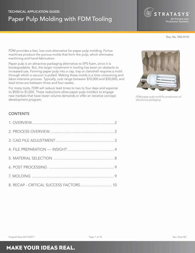
FDM provides a fast, low-cost alternative for paper pulp molding. Fortus machines produce the porous molds that form the pulp, which eliminates machining and hand-fabrication.
Paper pulp is an attractive packaging alternative to EPS foam, since it is biodegradable. But, the larger investment in tooling has been an obstacle to increased use. Forming paper pulp into a cap, tray or clamshell requires a mold through which a vacuum is pulled. Making these molds is a time-consuming and labor-intensive process. Typically, cost range between $10,000 and $30,000, and lead times are between three and four weeks.
For many tools, FDM will reduce lead times to two to four days and expense to $500 to $1,000. These reductions allow paper pulp molders to engage new markets that have lower volume demands or offer an iterative concept development program.
FDM paper pulp mold for production of electronics packaging.
MAKE YOUR IDEAS REAL.
TECHNICAL APPLICATION GUIDE:
Paper Pulp Molding with FDM Tooling
Original Date: 04/19/2011 Page 2 of 10 Rev. Date: NC
TECHNICAL APPLICATION GUIDE:
Paper Pulp Molding with FDM Tooling
Doc. No. TAG 07-01
1. OVERVIEW
1.1. Application:
FDM presents an alternative to the traditional tool-making process.
These procedures have been applied to Type 1 (thick-wall) and Type 2 (thin wall) paper pulp molding processes.
• Presently, no data on Type 3 (thermoformed fiber) processes.
− Success is likely, but yet to be attempted.
• Presently, no data on heat-press tooling or on-tool part drying.
− With proper FDM material selection and temperature management, success is probable, but yet to be attempted.
1.2. Tool life:
1.2.1. 30,000 or more cycles possible.
Tool life will be dependent on part/tool configuration, processing parameters and cycle rates.
1.3. FDM is a best fit when:
1.3.1. Low-volume prototype, bridge-to-production or production runs.
1.3.2. Tools size: less than 3 feet (0.9 meters) in length.
The only limit is practicality of large tool construction using available FDM Fortus systems.
1.3.3. Complex shapes.
The advantages of additive manufacturing will be greatest when the part, and therefore the tool, have organic shapes and/or numerous features.
2. PROCESS OVERVIEW
2.1. The steps in the traditional paper pulp molding process are:
2.1.1. Manufacture pulp molding tool (Figure 1).
2.1.1.1. Machine metal billet to net-shape.
2.1.1.2. Drill pattern of vacuum holes.
2.1.1.3. Cut, place and form screen over molding surfaces.
2.1.2. Manufacture transfer tool (Type 2 only).
2.1.2.1. Machine metal billet to shape.
2.1.2.2. Drill several vacuum channels.
2.1.3. Mount tool on a vacuum plate.
2.1.4. Manufacture paper pulp parts (Figure 2).
Figure 2: Paper pulp molding machine transfers the mold to the slurry tank and pulls a vacuum to draw pulp against the screen.
Figure 1: Paper pulp molds combine machined metal forms overlaid with hand-formed screens.
Molded packaging for electronic device and its accessories.
FDM paper pulp mold for production of electronics packaging.
Original Date: 04/19/2011 Page 3 of 10 Rev. Date: NC
TECHNICAL APPLICATION GUIDE:
Paper Pulp Molding with FDM Tooling
Doc. No. TAG 07-01
2.1.4.1. Submerge tool in paper slurry.
2.1.4.2. Pull vacuum to draw paper fibers against screen.
2.1.4.3. Remove tool (with part) from the slurry.
2.1.4.4. Eject part into transfer tool and transport to conveyor.
2.1.4.5. Dry part in oven.
2.2. Modifications.
To incorporate FDM tooling into the paper pulp molding process, adjustments, alterations and substitutions are made to the following steps:
2.2.1. Tool design.
Tool design is unchanged. However, the CAD model is broken down to two or more discrete files.
2.2.2. Manufacture pulp molding tool.
FDM replaces machined tool.
2.2.3. Manufacture transfer tool (optional).
FDM replaces machined transfer tool.
2.2.4. All other processes and methods remain unchanged.
3. CAD FILE ADJUSTMENT
3.1. CAD model.
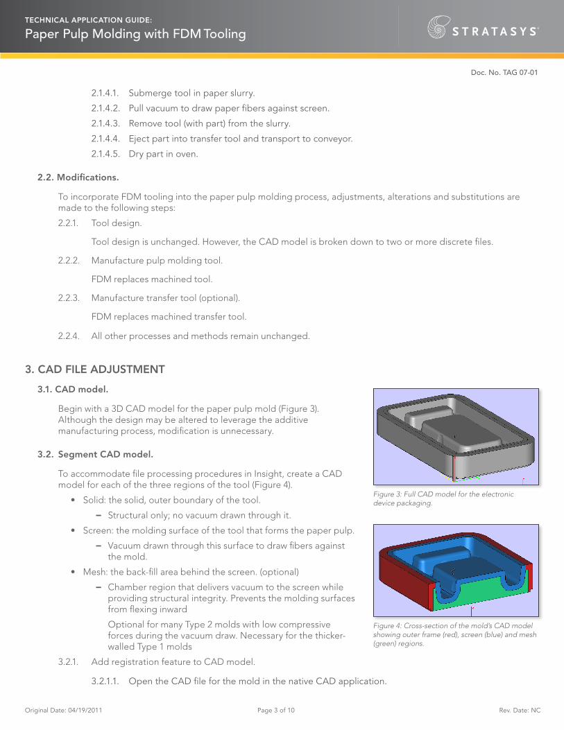
Begin with a 3D CAD model for the paper pulp mold (Figure 3). Although the design may be altered to leverage the additive manufacturing process, modification is unnecessary.
3.2. Segment CAD model.
To accommodate file processing procedures in Insight, create a CAD model for each of the three regions of the tool (Figure 4).
• Solid: the solid, outer boundary of the tool.
− Structural only; no vacuum drawn through it.
• Screen: the molding surface of the tool that forms the paper pulp.
− Vacuum drawn through this surface to draw fibers against the mold.
• Mesh: the back-fill area behind the screen. (optional)
− Chamber region that delivers vacuum to the screen while providing structural integrity. Prevents the molding surfaces from flexing inward
Optional for many Type 2 molds with low compressive forces during the vacuum draw. Necessary for the thicker-walled Type 1 molds
3.2.1. Add registration feature to CAD model.
3.2.1.1. Open the CAD file for the mold in the native CAD application.
Figure 4: Cross-section of the mold’s CAD model showing outer frame (red), screen (blue) and mesh (green) regions.
Figure 3: Full CAD model for the electronic device packaging.
Original Date: 04/19/2011 Page 4 of 10 Rev. Date: NC
TECHNICAL APPLICATION GUIDE:
Paper Pulp Molding with FDM Tooling
Doc. No. TAG 07-01
3.2.1.2. Construct a reference block at the origin (0,0,0).
Reference block will be located in front of and to the left of the CAD model. It must not impinge on the model. For reference orientation (mounting surfaces versus molding surfaces), recommend adding a distinguishing mark or feature to the top of the reference block.
• Reference block dimensions:
X & Y: Approximately 0.25 inch (6.4 mm)
Z: Height of tool + 0.10 inch (2.5 mm)
Reference block must be taller than the tool due to the slicing procedure in Insight.
Save the file (tool_original).
3.2.2. Create solid component.
3.2.2.1. Subtract all molding surfaces, and the material below, from the model (tool_original).
This will leave a solid “frame” around the boundary of the tool. (Figure 5)
3.2.2.2. Save the file (solid_file) and export the STL.
3.2.3. Create the screen component (Figure 6).
3.2.3.1. Open tool_original.
3.2.3.2. Import and subtract solid_file.
• Don’t subtract the reference block.
3.2.3.3. Create a 0.125-inch (3.18 mm) shell.
• Offset the outer surface towards the interior of the tool, and subtract all material below the offset.
3.2.3.4. Create a 0.001-inch (0.025 mm) clearance from the solid component.
3.2.3.5. Save the file (screen_file) and export the STL.
3.2.4. Create mesh component (optional).
3.2.4.1. Open tool_original.
3.2.4.2. Import and subtract both solid_file and screen_file.
• Don’t subtract the reference block.
3.2.4.3. Create a 0.001-inch (0.025 mm) clearance from the solid and screen components.
3.2.4.4. Save the file (mesh_file) and export the STL.
4. FILE PREPARATION — INSIGHT
A paper pulp mold must have good vacuum flow while minimizing clogging with paper fibers. To achieve this, process the STLs in Insight to create an FDM tool with good air flow, tight pores and smooth surfaces.
• This procedure uses a custom group library created specifically for paper pulp molding, Paper Pulp T16. It is available under the Import option in the Custom groups function.
• Complete all the file preparation steps in the Insight application.
• Note that the following process parameters may be adjusted to optimize operational performance.
Figure 5: Solid frame component.
Figure 6: Solid frame component.
Original Date: 04/19/2011 Page 5 of 10 Rev. Date: NC
TECHNICAL APPLICATION GUIDE:
Paper Pulp Molding with FDM Tooling
Doc. No. TAG 07-01
Additionally, some adjustments may be required on a feature level (see 4.4.11).
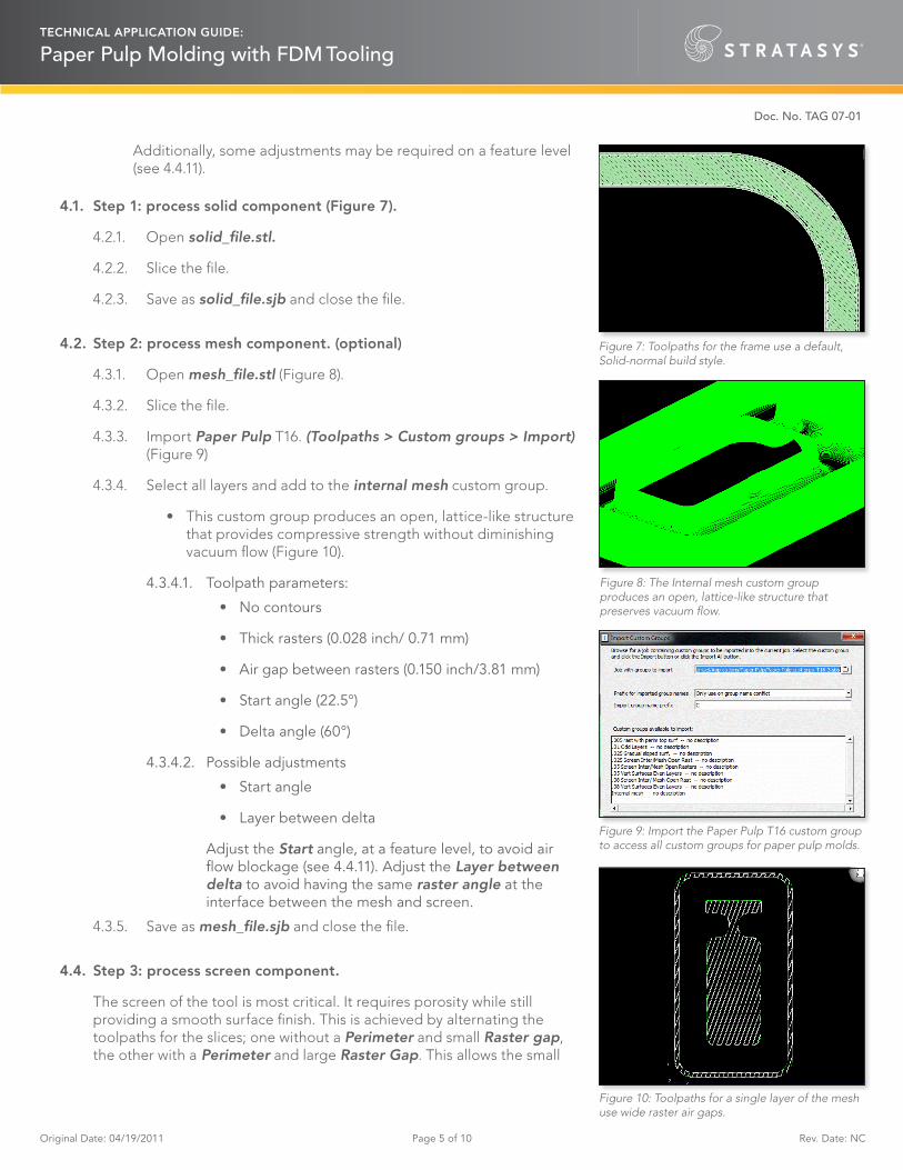
4.1. Step 1: process solid component (Figure 7).
4.2.1. Open solid_file.stl.
4.2.2. Slice the file.
4.2.3. Save as solid_file.sjb and close the file.
4.2. Step 2: process mesh component. (optional)
4.3.1. Open mesh_file.stl (Figure 8).
4.3.2. Slice the file.
4.3.3. Import Paper Pulp T16. (Toolpaths > Custom groups > Import) (Figure 9)
4.3.4. Select all layers and add to the internal mesh custom group.
• This custom group produces an open, lattice-like structure that provides compressive strength without diminishing vacuum flow (Figure 10).
4.3.4.1. Toolpath parameters:
• No contours
• Thick rasters (0.028 inch/ 0.71 mm)
• Air gap between rasters (0.150 inch/3.81 mm)
• Start angle (22.5°)
• Delta angle (60°)
4.3.4.2. Possible adjustments
• Start angle
• Layer between delta
Adjust the Start angle, at a feature level, to avoid air flow blockage (see 4.4.11). Adjust the Layer between delta to avoid having the same raster angle at the interface between the mesh and screen.
4.3.5. Save as mesh_file.sjb and close the file.
4.4. Step 3: process screen component.
The screen of the tool is most critical. It requires porosity while still providing a smooth surface finish. This is achieved by alternating the toolpaths for the slices; one without a Perimeter and small Raster gap, the other with a Perimeter and large Raster Gap. This allows the small
Figure 10: Toolpaths for a single layer of the mesh use wide raster air gaps.
Figure 8: The Internal mesh custom group produces an open, lattice-like structure that preserves vacuum flow.
Figure 9: Import the Paper Pulp T16 custom group to access all custom groups for paper pulp molds.
Figure 7: Toolpaths for the frame use a default, Solid-normal build style.
Original Date: 04/19/2011 Page 6 of 10 Rev. Date: NC
TECHNICAL APPLICATION GUIDE:
Paper Pulp Molding with FDM Tooling
Doc. No. TAG 07-01
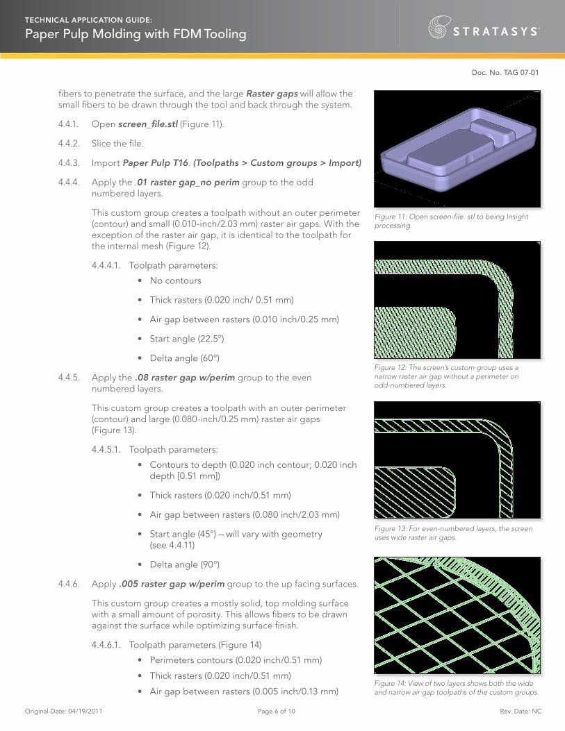
fibers to penetrate the surface, and the large Raster gaps will allow the small fibers to be drawn through the tool and back through the system.
4.4.1. Open screen_file.stl (Figure 11).
4.4.2. Slice the file.
4.4.3. Import Paper Pulp T16. (Toolpaths > Custom groups > Import)
4.4.4. Apply the .01 raster gap_no perim group to the odd numbered layers.
This custom group creates a toolpath without an outer perimeter (contour) and small (0.010-inch/2.03 mm) raster air gaps. With the exception of the raster air gap, it is identical to the toolpath for the internal mesh (Figure 12).
4.4.4.1. Toolpath parameters:
• No contours
• Thick rasters (0.020 inch/ 0.51 mm)
• Air gap between rasters (0.010 inch/0.25 mm)
• Start angle (22.5°)
• Delta angle (60°)
4.4.5. Apply the .08 raster gap w/perim group to the even numbered layers.
This custom group creates a toolpath with an outer perimeter (contour) and large (0.080-inch/0.25 mm) raster air gaps (Figure 13).
4.4.5.1. Toolpath parameters:
• Contours to depth (0.020 inch contour; 0.020 inch depth [0.51 mm])
• Thick rasters (0.020 inch/0.51 mm)
• Air gap between rasters (0.080 inch/2.03 mm)
• Start angle (45°) – will vary with geometry (see 4.4.11)
• Delta angle (90°)
4.4.6. Apply .005 raster gap w/perim group to the up facing surfaces.
This custom group creates a mostly solid, top molding surface with a small amount of porosity. This allows fibers to be drawn against the surface while optimizing surface finish.
4.4.6.1. Toolpath parameters (Figure 14)
• Perimeters contours (0.020 inch/0.51 mm)
• Thick rasters (0.020 inch/0.51 mm)
• Air gap between rasters (0.005 inch/0.13 mm)Figure 14: View of two layers shows both the wide and narrow air gap toolpaths of the custom groups.
Figure 13: For even-numbered layers, the screen uses wide raster air gaps.
Figure 11: Open screen-file. stl to being Insight processing.
Figure 12: The screen’s custom group uses a narrow raster air gap without a perimeter on odd-numbered layers.
Original Date: 04/19/2011 Page 7 of 10 Rev. Date: NC
TECHNICAL APPLICATION GUIDE:
Paper Pulp Molding with FDM Tooling
Doc. No. TAG 07-01
• Start angle (45°) – may vary with geometry (see 4.4.11)
• Delta angle (90°)
4.4.7. Review the slice below each up facing surface.
If it is part of the .08 raster gap w/perim group, change it to the .01 raster gap_no perim group.
The smaller raster gap of the .01 raster gap_no perim group produces a smoother upfacing surface. With the large raster gap of the .08 raster gap w/perim group, the visible surface rasters can dip as they bridge the 0.080 inch (2.03 mm) gap.
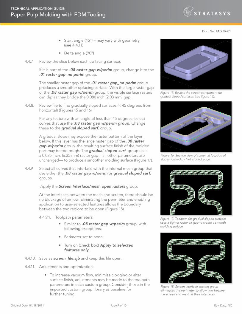
4.4.8. Review file to find gradually sloped surfaces (< 45 degrees from horizontal) (Figures 15 and 16).
For any feature with an angle of less than 45 degrees, select curves that use the .08 raster gap w/perim group. Change these to the gradual sloped surf. group.
A gradual slope may expose the raster pattern of the layer below. If this layer has the large raster gap of the .08 raster gap w/perim group, the resulting surface finish of the molded part may be too rough. The gradual sloped surf. group uses a 0.025 inch. (6.35 mm) raster gap—all other parameters are unchanged— to produce a smoother molding surface (Figure 17).
4.4.9. Select all curves that interface with the internal mesh group that use either the .08 raster gap w/perim or gradual sloped surf. groups.
Apply the Screen Interface/mesh open rasters group.
At the interfaces between the mesh and screen, there should be no blockage of airflow. Eliminating the perimeter and enabling application to user-selected features allows the boundary between the two regions to be open (Figure 18).
4.4.9.1. Toolpath parameters:
• Similar to .08 raster gap w/perim group, with following exceptions:
• Perimeter set to none.
• Turn on (check box) Apply to selected features only.
4.4.10. Save as screen_file.sjb and keep this file open.
4.4.11. Adjustments and optimization:
• To increase vacuum flow, minimize clogging or alter surface finish, adjustments may be made to the toolpath parameters in each custom group. Consider those in the imported custom group library as baseline for further tuning.
Figure 15: Review the screen component for gradual sloped surfaces (see figure 16).
Figure 16: Section view of screen at location of slopes formed by filet around edge.
Figure 17: Toolpath for gradual sloped surfaces uses a tighter raster air gap to create a smooth molding surface.
Figure 18: Screen interface custom group eliminates the perimeter to allow flow between the screen and mesh at their interfaces.
Original Date: 04/19/2011 Page 8 of 10 Rev. Date: NC
TECHNICAL APPLICATION GUIDE:
Paper Pulp Molding with FDM Tooling
Doc. No. TAG 07-01
• Note that part geometries may dictate adjustments to toolpaths. This is most often the case for large radii corners or angled (in XY plane) surfaces.
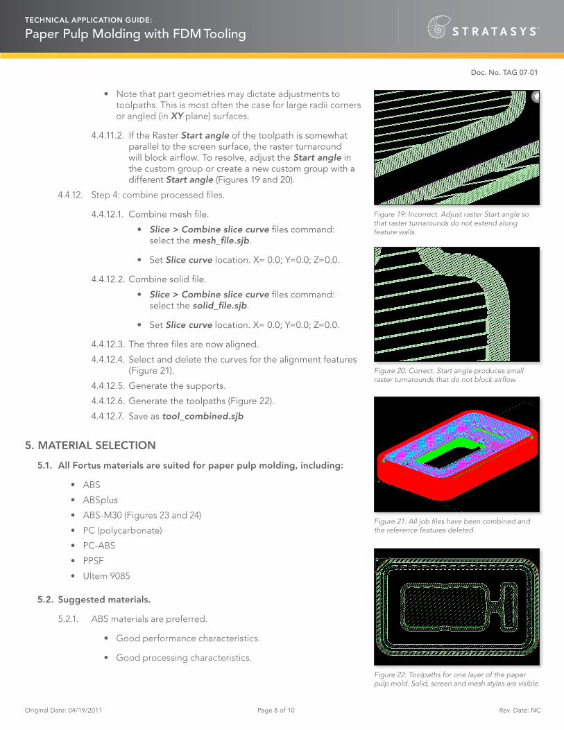
4.4.11.2. If the Raster Start angle of the toolpath is somewhat parallel to the screen surface, the raster turnaround will block airflow. To resolve, adjust the Start angle in the custom group or create a new custom group with a different Start angle (Figures 19 and 20).
4.4.12.4. Select and delete the curves for the alignment features (Figure 21).
4.4.12.5. Generate the supports.
4.4.12.6. Generate the toolpaths (Figure 22).
4.4.12.7. Save as tool_combined.sjb
5. MATERIAL SELECTION
5.1. All Fortus materials are suited for paper pulp molding, including:
• ABS
• ABSplus
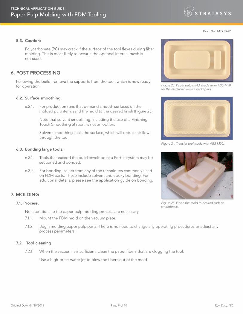
• ABS-M30 (Figures 23 and 24)
• PC (polycarbonate)
• PC-ABS
• PPSF
• Ultem 9085
5.2. Suggested materials.
5.2.1. ABS materials are preferred.
• Good performance characteristics.
• Good processing characteristics.
Figure 19: Incorrect. Adjust raster Start angle so that raster turnarounds do not extend along feature walls.
Figure 20: Correct. Start angle produces small raster turnarounds that do not block airflow.
Figure 21: All job files have been combined and the reference features deleted.
Figure 22: Toolpaths for one layer of the paper pulp mold. Solid, screen and mesh styles are visible.
Original Date: 04/19/2011 Page 9 of 10 Rev. Date: NC
TECHNICAL APPLICATION GUIDE:
Paper Pulp Molding with FDM Tooling
Doc. No. TAG 07-01
5.3. Caution:
Polycarbonate (PC) may crack if the surface of the tool flexes during fiber molding. This is most likely to occur if the optional internal mesh is not used.
6. POST PROCESSING
Following the build, remove the supports from the tool, which is now ready for operation.
6.2. Surface smoothing.
6.2.1. For production runs that demand smooth surfaces on the molded pulp item, sand the mold to the desired finish (Figure 25).
Note that solvent smoothing, including the use of a Finishing Touch Smoothing Station, is not an option.
Solvent smoothing seals the surface, which will reduce air flow through the tool.
6.3. Bonding large tools.
6.3.1. Tools that exceed the build envelope of a Fortus system may be sectioned and bonded.
6.3.2. For bonding, select from any of the techniques commonly used on FDM parts. These include solvent and epoxy bonding. For additional details, please see the application guide on bonding.
7. MOLDING
7.1. Process.
No alterations to the paper pulp molding process are necessary
7.1.1. Mount the FDM mold on the vacuum plate.
7.1.2. Begin molding paper pulp parts. There is no need to change any operating procedures or adjust any process parameters.
7.2. Tool cleaning.
7.2.1. When the vacuum is insufficient, clean the paper fibers that are clogging the tool.
Use a high-press water jet to blow the fibers out of the mold.
Figure 23: Paper pulp mold, made from ABS-M30, for the electronic device packaging
Figure 25: Finish the mold to desired surface smoothness.
Figure 24: Transfer tool made with ABS-M30.
Doc. No. TAG 07-01
TECHNICAL APPLICATION GUIDE:
Paper Pulp Molding with FDM Tooling
Original Date 04/19/2011 Page 10 of 10 Rev. Date NC


![Improving the quality of the molded polymeric parts by ... the quality of the molded polymeric parts by reducing . the residual stress . ... other engineering studies, [4]. Design](https://static.documents.pub/doc/80x56/5af237887f8b9ac57a90ea26/improving-the-quality-of-the-molded-polymeric-parts-by-the-quality-of-the-molded.jpg)


