Convey or Belt Install ations and Rel ated Components Print CONVEYOR SKIRTS. The sides of the feed chute are also provided with skirtboards to prevent rock spillage and to centralise the load to the centre of the belt. Skirtboards are set at a 45 degree angle to the belt. The skirtboard is never brought down tight against the belt surface, but is left with a substantial clearance of approximately 25 mm which is closed with a soft rubber strip. Figure 1 Principles of Skirts The task of the skirting is important because dirty conveyors cost money. To fully understand the economic impact, as well as skirting's role in controlling fugitive material, let's first clarify some terms. What is referred to as "skirting" is the lower portion of the loading chute that deposits the material onto the conveyor belt. Figure 2: The lower portion of the loading chute that deposits material onto the conveyor belt. Figure 2a: End view of transfer with material loaded onto the belt. A = skirts ste el's low point. B = idlers' high point. This area is most often called the Transfer Point. The material at the Transfer Point is dramatically changing. It goes from one condition to another, from one direction to another, and from one velocity to another. Predominantly, Transfer Points occur where one conveyor discharges the material into another conveyor (See Figure 3) . 4/16/2011 Conveyor Learning Website saimh.co.za/education/…/index.html 1/4 03 Jul, 2012 NOTE Update : 03 July 2012
Transcript
Conveyor Belt Installations and Related ComponentsPrint
CONVEYOR SKIRTS.
The sides of the feed chute are also provided with skirtboards to prevent rock spillage
and to centralise the load to the centre of the belt. Skirtboards are set at a 45 degree
angle to the belt. The skirtboard is never brought down tight against the belt surface,
but is left with a substantial clearance of approximately 25 mm which is closed with a
soft rubber strip.
Figure 1
Principles of Skirts
The task of the skirting is important because dirty conveyors cost money. To fully
understand the economic impact, as well as skirting's role in controlling fugitive material,
let's first clarify some terms. What is referred to as "skirting" is the lower portion of the
loading chute that deposits the material onto the conveyor belt.
Figure 2: The lower portion of the loading chute that deposits material onto the
conveyor belt.
Figure 2a: End view of transfer with material loaded onto the belt.
A = skirts steel's low point. B = idlers' high point.
This area is most often called the Transfer Point. The material at the Transfer Point is
dramatically changing. It goes from one condition to another, from one direction to
another, and from one velocity to another. Predominantly, Transfer Points occur whereone conveyor discharges the material into another conveyor (See Figure 3) .
4/16/2011 Conveyor Learning Website
saimh.co.za/education/…/index.html 1/4
03 Jul,
2012
NOTE
Update :
03 July 2012
Figure 3: Typical transfer from one conveyor to another.
As the material being transferred tries to obtain the speed and direction of the belt it
becomes turbulent. The falling, bouncing, tumbling and impacting of lump on lump,
particle to particle has been the subject of countless studies, all directed at how to
center the cargo or how to increase the life of the conveyor belt. While this is a most
important consideration that should receive high priority in the design, it must not
exclude that other, equally important design requirement : A CLEAN CONVEYOR.
Figure 4: Materials profile as designer
calculates it 3/4-width of belt --
common design practices.
Figure 5: Actual profile because of turbulence at transfer occupies more
space. Extreme side pressure is exerted
on rubber seal.
Figure 6: End view showing deflector
lines positioned above conveyor belt.
Figure 7: Deflector wearliner is positioned
to guide the material on the belt, with
means of adjustment, to keep material
pressure from the rubber seal.
Figure 8: Cast blocks when used as
wearliner must be placed evenly so as
to assure smooth flow of the cargo
along its bottom surface.
Figure 9: Wide-spaced idlers permit belt
to sag and tambourine from material
impact, encouraging
material to escape.
4/16/2011 Conveyor Learning Website
saimh.co.za/education/…/index.html 2/4
REPRODUCTION
Figure 10: Close-set idlers keep belt
flat and prevent tambourine effect
Figure 11: Skirt wears above idlers --
adjustment becomes impossible because
scalloped wear pattern does not match
belt's running profile.
Figure 12: Figure 13:
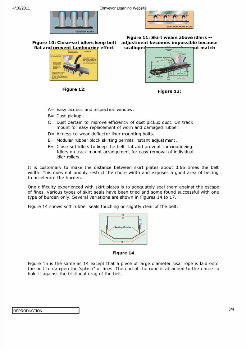
A= Easy access and inspect ion window.
B= Dust pickup.
C= Dust certain to improve efficiency of dust pickup duct. On trackmount for easy replacement of worn and damaged rubber.