34
Architectural Engineering 2012 Senior Thesis Advisor: Dr. Robert Leicht 2012 Technical Assignment 1 Reston Station Phase 1 Garage | Reston, VA Jonathan A Fisher
-+
+
Architectural Engineering 2012 Senior Thesis
A d v i s o r : D r . R o b e r t L e i c h t
2012
Technical Assignment 1
Reston Station Phase 1 Garage | Reston, VA
Jonathan A Fisher
TECHNICAL ASSIGNMENT 1 September 21, 2012
Jon Fisher | Technical Assignment 1 | September 21, 2012 Page 1
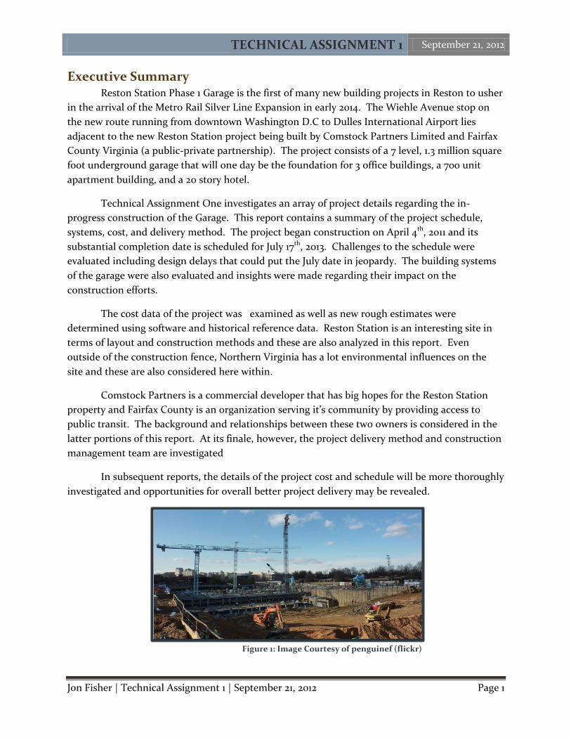
Executive Summary Reston Station Phase 1 Garage is the first of many new building projects in Reston to usher
in the arrival of the Metro Rail Silver Line Expansion in early 2014. The Wiehle Avenue stop on
the new route running from downtown Washington D.C to Dulles International Airport lies
adjacent to the new Reston Station project being built by Comstock Partners Limited and Fairfax
County Virginia (a public-private partnership). The project consists of a 7 level, 1.3 million square
foot underground garage that will one day be the foundation for 3 office buildings, a 700 unit
apartment building, and a 20 story hotel.
Technical Assignment One investigates an array of project details regarding the in-
progress construction of the Garage. This report contains a summary of the project schedule,
systems, cost, and delivery method. The project began construction on April 4th, 2011 and its
substantial completion date is scheduled for July 17th, 2013. Challenges to the schedule were
evaluated including design delays that could put the July date in jeopardy. The building systems
of the garage were also evaluated and insights were made regarding their impact on the
construction efforts.
The cost data of the project was examined as well as new rough estimates were
determined using software and historical reference data. Reston Station is an interesting site in
terms of layout and construction methods and these are also analyzed in this report. Even
outside of the construction fence, Northern Virginia has a lot environmental influences on the
site and these are also considered here within.
Comstock Partners is a commercial developer that has big hopes for the Reston Station
property and Fairfax County is an organization serving it’s community by providing access to
public transit. The background and relationships between these two owners is considered in the
latter portions of this report. At its finale, however, the project delivery method and construction
management team are investigated
In subsequent reports, the details of the project cost and schedule will be more thoroughly
investigated and opportunities for overall better project delivery may be revealed.
Figure 1: Image Courtesy of penguinef (flickr)
TECHNICAL ASSIGNMENT 1 September 21, 2012
Jon Fisher | Technical Assignment 1 | September 21, 2012 Page 2
Table of Contents Executive Summary ................................................................................................................................ 1
Project Schedule Summary ................................................................................................................... 3
Building Systems ................................................................................................................................... 5
Project Cost ........................................................................................................................................... 8
Site Plan ................................................................................................................................................. 9
Local Conditions .................................................................................................................................. 11
Client Information ............................................................................................................................... 13
Project Delivery .................................................................................................................................... 15
Staffing Plan ......................................................................................................................................... 17
APPENDIX A: Project Summary Schedule .......................................................................................... 19
APPENDIX B-1: Existing Site Conditions ............................................................................................ 21
APPENDIX B-2: Excavation Phase Site Plan ...................................................................................... 23
APPENDIX B-3: tructure Phase Site Plan ........................................................................................... 25
APPENDIX B-4: Finishes & Enclosure Phase Site Plan ...................................................................... 27
APPENDIX C-1: Square Foot Cost Estimate Data .............................................................................. 29
APPENDIX C-2: Assembly Cost Estimate Data ................................................................................... 31

TECHNICAL ASSIGNMENT 1 September 21, 2012
Jon Fisher | Technical Assignment 1 | September 21, 2012 Page 3
Figure 2: Octant Phasing Layout
Project Schedule Summary
The Dulles Corridor Metrorail Project, otherwise known as the Metro Silver Line
Expansion, is the overarching public transit project dictating the schedule for the Reston Station
Garage. With plans for phase 1 of the new rail line to be operational at the beginning of 2014,
Fairfax County must ensure that adequate parking is available for commuters that will be using
the rail system daily. Fairfax County and Comstock Partner (a public-private partnership) chose
to negotiate a Construction Manager at-risk contract with DAVIS Construction at an early stage
in design of the garage project, which created unique situations and challenges in the schedule for
construction. A summary schedule of the project, including phases of pre-construction,
procurement, construction trades, and inspections/occupancy can be found in appendix A of this
report.
Comstock Partners, the private entity of the owner team, requested DAVIS to assist with
pre-construction in early 2010. At that point in time only schematic drawings were available for
the purpose of coordinating construction efforts. Design Development drawings were completed
in August of 2010 and a permit set of drawings were submitted on January 21st 2011. The formal
notice to proceed for the project was issued for April 4th, 2011. The construction of the project was
begun with an in-progress design that was planned to be completed in June of 2011.
The biggest schedule risk to the Reston Station Phase 1 Garage Project was design delays
due to the attempt at a fast track project delivery (construction beginning without 100% design).
This issue slowed on-site production considerably due to challenges in concrete shop drawing
production and trade coordination. As of this date, complete construction drawings are planned
to be complete in October of 2012, 16 months late. One major component causing the delay of
design is the ongoing design of the buildings planned to go on top of the garage structure. This
issue will be discussed in further detail in subsequent technical assignments.
The entire project was phased using an
octant system to designate zones. Generally, all
trades were to begin work in octant A in the
North West corner of the building site and
progress in sequence through the remaining
octants B through H. A visual of this system in
plan view can be seen in Figure 2. This system
works well as several octants could be grouped
together depending on the particular flow of
work for any given trade. The construction
sequences of the foundation, structural system,
and finishes are available below.
TECHNICAL ASSIGNMENT 1 September 21, 2012
Jon Fisher | Technical Assignment 1 | September 21, 2012 Page 4
Foundation
After almost 4 months of excavation to a depth of approximately 70 feet below original
grade foundation activities were able to begin in octants A and B. Footings for columns, walls,
and tower cranes were to be poured first. Following this a 5 inch slab on grade garage floor was
poured into place. Formwork assembly for the footings began in octants A and B more than a full
month before the excavation was complete in neighboring octants C and D.
The events that had the biggest impact on foundation construction were two natural
disasters that occurred in August of 2011. The 2011 Virginia Earthquake occurred in the afternoon
of August 23rd and 4 days later, on the 27th, Hurricane Irene caused 5 feet of water to accumulate
in the excavation. These events and their effect on the schedule of the project will be discussed
further in future technical assignments.
Structural The structural sequencing of the project is driven by the concrete trade. The Western
progress of the building consistently stayed 2 levels ahead of the Eastern half due to the phasing
of trades. The building separation joint that runs north to south along column line 11 serves as
dividing line between these progressions. Drawings, submittals, and work for the concrete trade
are all organized in terms of octants. Within each of the eight octants there are approximately 6
separate slab pours. Typically, one slab pour occurs every work day.
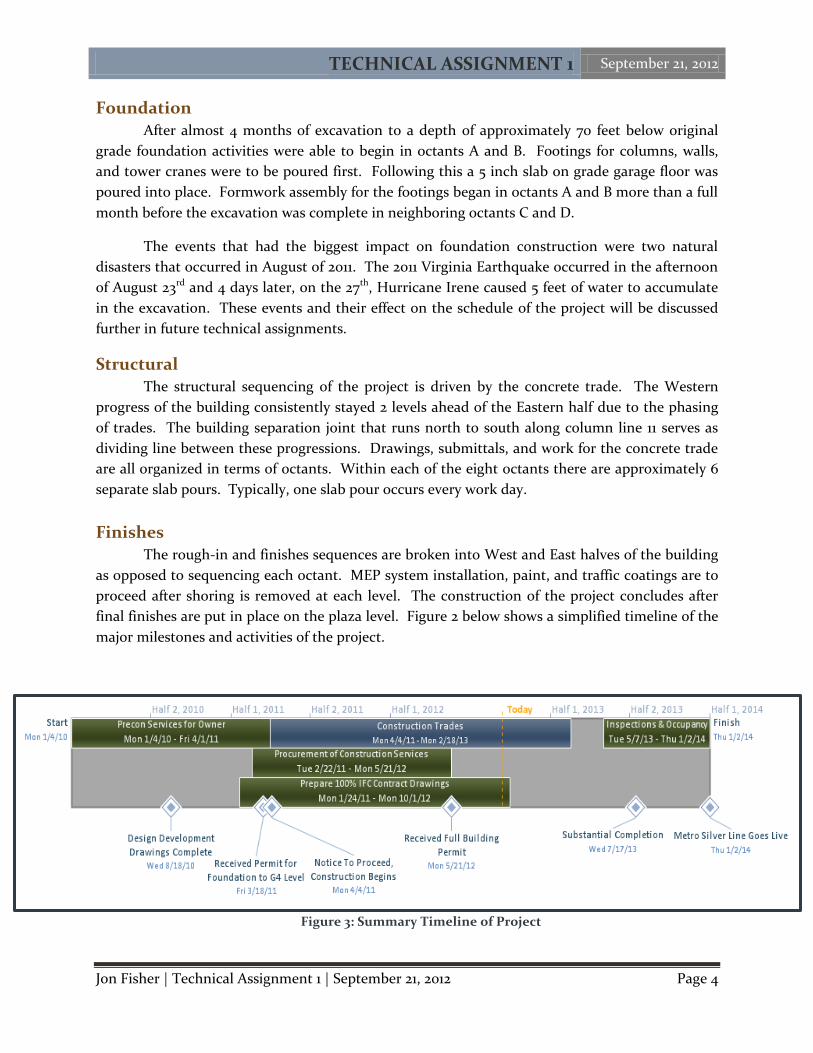
Finishes The rough-in and finishes sequences are broken into West and East halves of the building
as opposed to sequencing each octant. MEP system installation, paint, and traffic coatings are to
proceed after shoring is removed at each level. The construction of the project concludes after
final finishes are put in place on the plaza level. Figure 2 below shows a simplified timeline of the
major milestones and activities of the project.
Figure 3: Summary Timeline of Project
TECHNICAL ASSIGNMENT 1 September 21, 2012
Jon Fisher | Technical Assignment 1 | September 21, 2012 Page 5
Building Systems
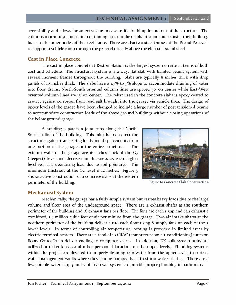
Demolition
The demolition at the Reston Station site
consisted of the removal of an existing parking lot that
was at existing grade level. There were also several utility
lines that required relocation or removal. The parking lot
was an approximate area of 170,000 square feet and was
predominately asphalt with concrete 8” curbs. The
demolition of the lot was performed with excavators,
front end loaders, and other typical excavation
equipment. Figure 3 to the right shows active demolition
of the asphalt lot.
There are several considerations for existing utilities that must be removed or relocated in
the excavation process as well. An underground electrical and cable television line running up
the east side of the site must be safely relocated. In addition, an abandon water line to the
southeast of the site needs to be removed.
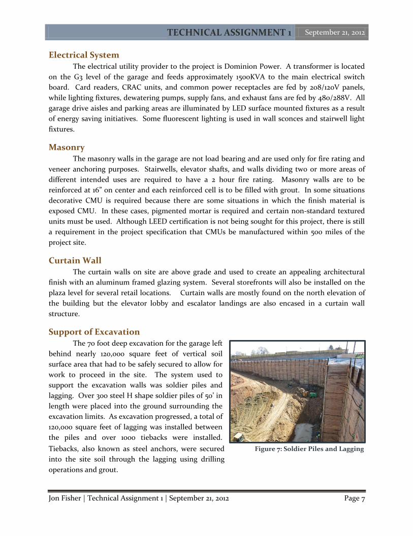
Structural Steel
Although the parking structure is a concrete two way
slab system, there are unique instances in the structure where
structural steel is utilized. In particular, a design feature
known as the “elephant stand” is a network of transfer girders
on the G1 level used to span a 60’ by 60’ area at the main
vehicle entrance to the garage. The typical column spacing in
the garage is 30’ on center but at the elephant stand, two
concentric squares made of W36x650 steel members are
incased in 48”x48” concrete beams to span 60’. The steel
members assembled in place prior to concrete encasement can
be seen in Figure 4 to the left. The opening allows for easier car
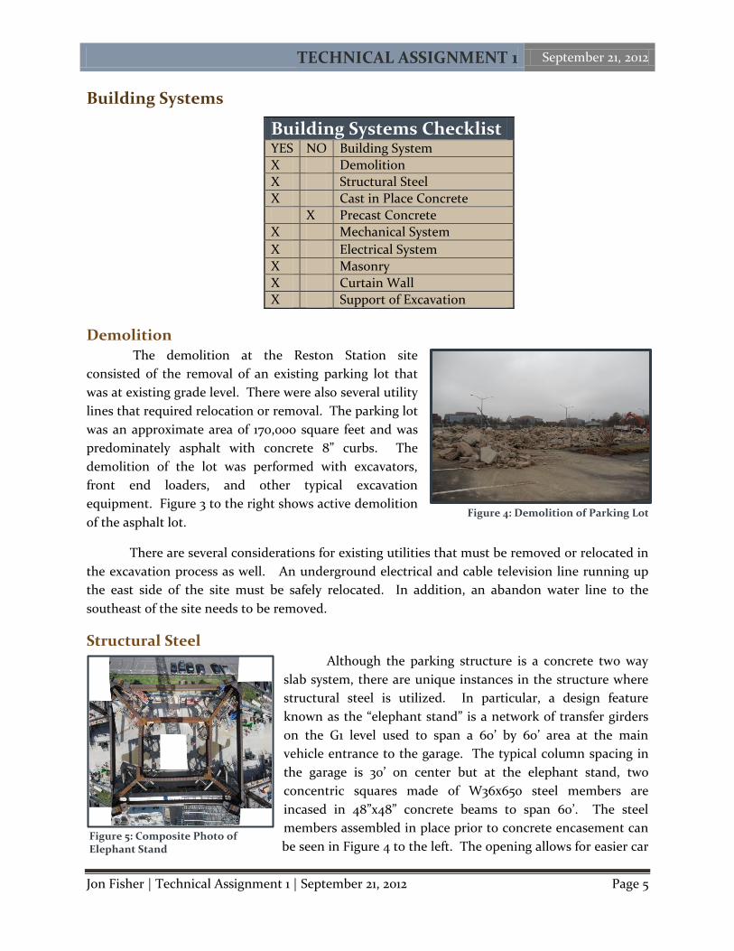
Building Systems Checklist YES NO Building System
X Demolition
X Structural Steel
X Cast in Place Concrete
X Precast Concrete
X Mechanical System
X Electrical System
X Masonry
X Curtain Wall
X Support of Excavation
Figure 4: Demolition of Parking Lot
Figure 5: Composite Photo of Elephant Stand
TECHNICAL ASSIGNMENT 1 September 21, 2012
Jon Fisher | Technical Assignment 1 | September 21, 2012 Page 6
accessibility and allows for an extra lane to ease traffic build up in and out of the structure. The
columns return to 30’ on center continuing up from the elephant stand and transfer their building
loads to the inner nodes of the steel frame. There are also two steel trusses at the P1 and P2 levels
to support a vehicle ramp through the p2 level directly above the elephant stand steel.
Cast in Place Concrete The cast in place concrete at Reston Station is the largest system on site in terms of both
cost and schedule. The structural system is a 2-way, flat slab with banded beams system with
several moment frames throughout the building. Slabs are typically 8 inches thick with drop
panels of 10 inches thick. The slabs have a 1.5% to 3% slope to accommodate draining of water
into floor drains. North-South oriented column lines are spaced 30’ on center while East-West
oriented column lines are 15’ on center. The rebar used in the concrete slabs is epoxy coated to
protect against corrosion from road salt brought into the garage via vehicle tires. The design of
upper levels of the garage have been changed to include a large number of post tensioned beams
to accommodate construction loads of the above ground buildings without closing operations of
the below ground garage.
A building separation joint runs along the North-
South 11 line of the building. This joint helps protect the
structure against transferring loads and displacements from
one portion of the garage to the entire structure. The
exterior walls of the garage are 16 inches thick at the G7
(deepest) level and decrease in thickness as each higher
level resists a decreasing load due to soil pressures. The
minimum thickness at the G2 level is 12 inches. Figure 5
shows active construction of a concrete slabs at the eastern
perimeter of the building.
Mechanical System
Mechanically, the garage has a fairly simple system but carries heavy loads due to the large
volume and floor area of the underground space. There are 4 exhaust shafts at the southern
perimeter of the building and 16 exhaust fans per floor. The fans are each 1.5hp and can exhaust a
combined, 1.4 million cubic feet of air per minute from the garage. Two air intake shafts at the
northern perimeter of the building deliver air to each floor using 8 supply fans on each of the 5
lower levels. In terms of controlling air temperature, heating is provided in limited areas by
electric terminal heaters. There are a total of 19 CRAC (computer room air-conditioning) units on
floors G7 to G2 to deliver cooling to computer spaces. In addition, DX split-system units are
utilized in ticket kiosks and other personnel locations on the upper levels. Plumbing systems
within the project are devoted to properly draining rain water from the upper levels to surface
water management vaults where they can be pumped back to storm water utilities. There are a
few potable water supply and sanitary sewer systems to provide proper plumbing to bathrooms.
Figure 6: Concrete Slab Construction
TECHNICAL ASSIGNMENT 1 September 21, 2012
Jon Fisher | Technical Assignment 1 | September 21, 2012 Page 7
Electrical System
The electrical utility provider to the project is Dominion Power. A transformer is located
on the G3 level of the garage and feeds approximately 1500KVA to the main electrical switch
board. Card readers, CRAC units, and common power receptacles are fed by 208/120V panels,
while lighting fixtures, dewatering pumps, supply fans, and exhaust fans are fed by 480/288V. All
garage drive aisles and parking areas are illuminated by LED surface mounted fixtures as a result
of energy saving initiatives. Some fluorescent lighting is used in wall sconces and stairwell light
fixtures.
Masonry The masonry walls in the garage are not load bearing and are used only for fire rating and
veneer anchoring purposes. Stairwells, elevator shafts, and walls dividing two or more areas of
different intended uses are required to have a 2 hour fire rating. Masonry walls are to be
reinforced at 16” on center and each reinforced cell is to be filled with grout. In some situations
decorative CMU is required because there are some situations in which the finish material is
exposed CMU. In these cases, pigmented mortar is required and certain non-standard textured
units must be used. Although LEED certification is not being sought for this project, there is still
a requirement in the project specification that CMUs be manufactured within 500 miles of the
project site.
Curtain Wall
The curtain walls on site are above grade and used to create an appealing architectural
finish with an aluminum framed glazing system. Several storefronts will also be installed on the
plaza level for several retail locations. Curtain walls are mostly found on the north elevation of
the building but the elevator lobby and escalator landings are also encased in a curtain wall
structure.
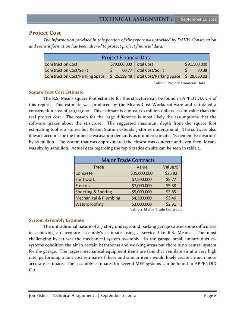
Support of Excavation
The 70 foot deep excavation for the garage left
behind nearly 120,000 square feet of vertical soil
surface area that had to be safely secured to allow for
work to proceed in the site. The system used to
support the excavation walls was soldier piles and
lagging. Over 300 steel H shape soldier piles of 50’ in
length were placed into the ground surrounding the
excavation limits. As excavation progressed, a total of
120,000 square feet of lagging was installed between
the piles and over 1000 tiebacks were installed.
Tiebacks, also known as steel anchors, were secured
into the site soil through the lagging using drilling
operations and grout.
Figure 7: Soldier Piles and Lagging
TECHNICAL ASSIGNMENT 1 September 21, 2012
Jon Fisher | Technical Assignment 1 | September 21, 2012 Page 8
Construction Cost 79,000,000$ Total Cost 91,500,000$
Construction Cost/Sq Ft 60.77$ Total Cost/Sq Ft 70.38$
Construction Cost/Parking Space 25,599.48$ Total Cost/Parking Space 29,650.03$
Project Financial Data
Trade Value Value/SF
Concrete $35,000,000 $26.92
Earthwork $7,500,000 $5.77
Electrical $7,000,000 $5.38
Sheeting & Shoring $5,000,000 $3.85
Mechanical & Plumbing $4,500,000 $3.46
Waterproofing $3,000,000 $2.31
Major Trade Contracts
Project Cost The information provided in this portion of the report was provided by DAVIS Construction
and some information has been altered to protect project financial data.
Square Foot Cost Estimate
The R.S. Means square foot estimate for this structure can be found in APPENDIX C-1 of
this report. This estimate was produced by the Means Cost Works software and it totaled a
construction cost of $50,151,000. This estimate is almost $30 million dollars less in value than the
real project cost. The reason for the large difference is most likely the assumptions that the
software makes about the structure. The suggested maximum depth from the square foot
estimating tool is 2 stories but Reston Station extends 7 stories underground. The software also
doesn’t account for the immense excavation demands as it underestimates “Basement Excavation”
by $6 million. The system that was approximated the closest was concrete and even then, Means
was shy by $5million. Actual data regarding the top 6 trades on site can be seen in table 2.
System Assembly Estimate
The untraditional nature of a 7 story underground parking garage causes some difficulties
in achieving an accurate assembly’s estimate using a service like R.S. Means. The most
challenging by far was the mechanical system assembly. In the garage, small unitary ductless
systems condition the air in certain bathrooms and working areas but there is no central system
for the garage. The largest mechanical equipment items are fans that ventilate air at a very high
rate, performing a unit cost estimate of these and similar items would likely create a much more
accurate estimate. The assembly estimates for several MEP systems can be found in APPENDIX
C-2.
Table 1: Project Financial Data
Table 2: Major Trade Contracts
TECHNICAL ASSIGNMENT 1 September 21, 2012
Jon Fisher | Technical Assignment 1 | September 21, 2012 Page 9
Site Plan
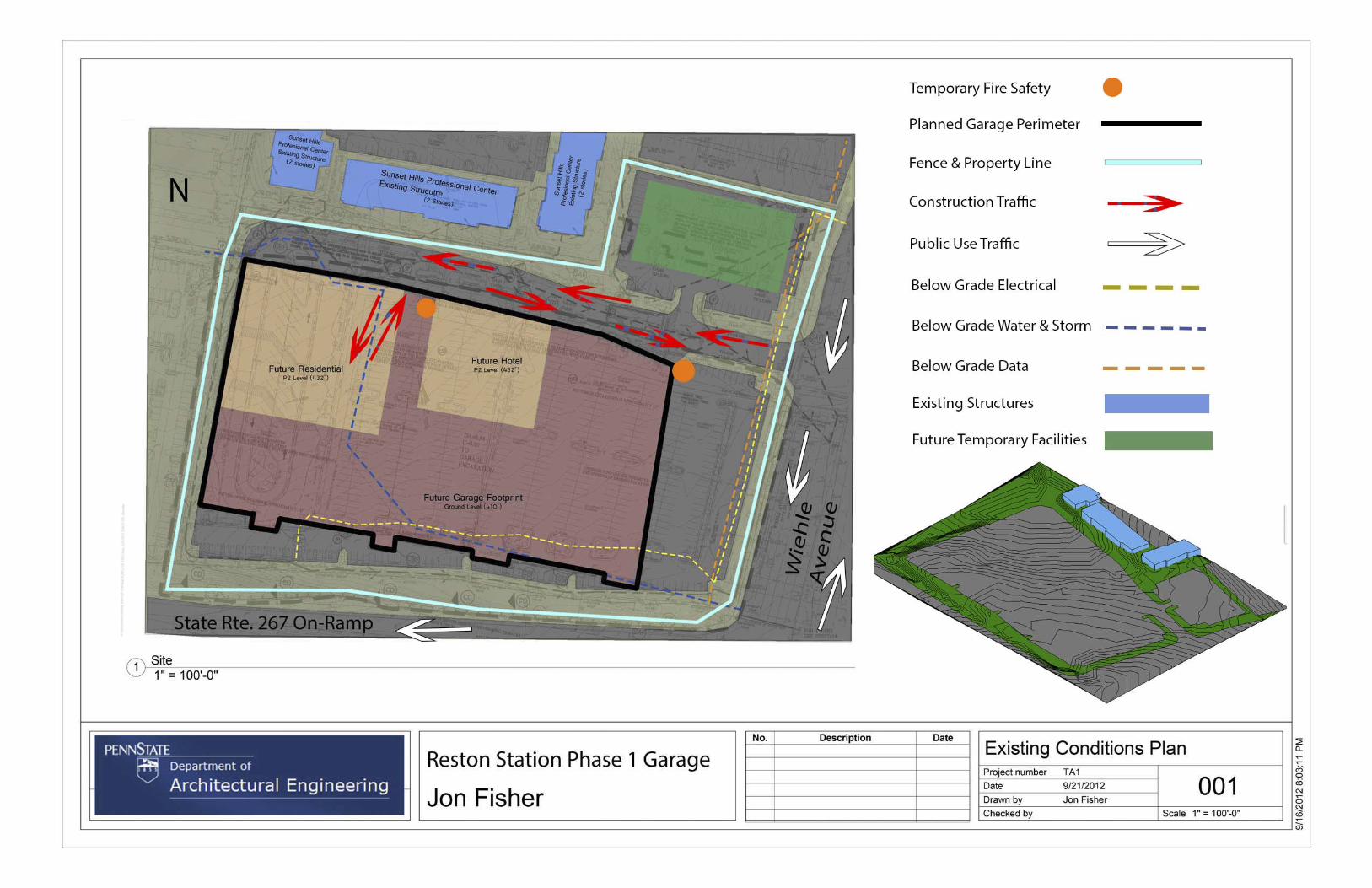
Existing Conditions
The Reston Station project site sat directly on top of the parking lot for the previous Metro
Bus stop at Wiehle Ave. After closure of this lot, Metro Bus operations were moved one block to
the north where street side stops currently occur alongside an annex parking lot. Site logistics on
a project the size of Reston Station are incredibly important to the flow of work and efficiency of
the project. An existing site layout plan in available in APPENDIX B-1 of this report. The site’s
closest neighbors are in the Sunset Hills Professional Center, a group of 3, two story office
buildings that are also owned by Comstock Partners. While the properties are owned by the same
owner, tenant considerations prohibit construction activities to leave the boundaries of
construction at Reston Station.
The site is bordered to the East by Wiehle Avenue. This asphalt road is 4 lanes at the
entrance to the site with a traffic light and turning lanes accommodating traffic into and out of
the site. Once construction vehicles are in the site during preliminary phases it is possible for
equipment to proceed to its intended location with little consideration for limitations within the
site.
A small adjacent lot at the North East corner of the site provides ample space for
construction trailers, waste dumpsters, material laydown area, and equipment storage containers.
At the height of construction this space was able to accommodate 8 to 10 trailers plus over 60
personal vehicles.
Existing utility line locations are a vital aspect of the initial stages of construction due to
the depth and size of the excavation required. There is a buried electrical line that used to power
parking lot street lights running along the south perimeter of the future garage’s footprint. Also,
an abandoned storm sewer line cuts across the entire building footprint between 4 and 5 feet
below grade.
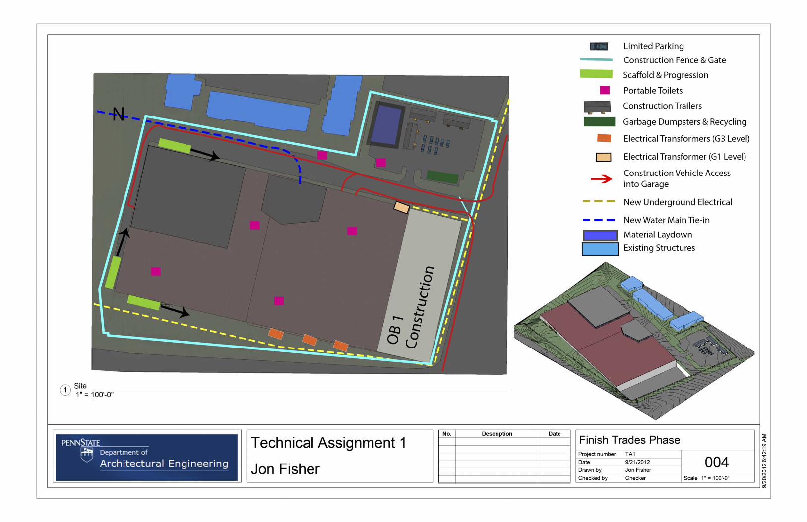
Construction Site Plan
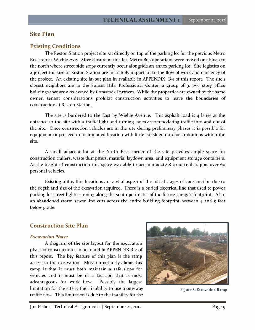
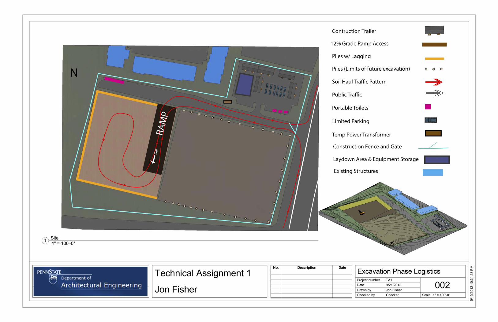
Excavation Phase
A diagram of the site layout for the excavation
phase of construction can be found in APPENDIX B-2 of
this report. The key feature of this plan is the ramp
access to the excavation. Most importantly about this
ramp is that it must both maintain a safe slope for
vehicles and it must be in a location that is most
advantageous for work flow. Possibly the largest
limitation for the site is their inability to use a one-way
traffic flow. This limitation is due to the inability for the Figure 8: Excavation Ramp
TECHNICAL ASSIGNMENT 1 September 21, 2012
Jon Fisher | Technical Assignment 1 | September 21, 2012 Page 10
site to have 2 ramps as well as the work being done directly to the east of the site on Office
Building 1 (OB1). The best solution to this problem is to allow two-way traffic on site except while
driving on the ramp.
Another consideration for the layout of the site is that piles must be driven before
excavation begins in any given area because of lagging and excavation support concerns.
Excavating at one end and slowly moving the ramp and excavation back towards the opposite wall
makes clear sense. Considering the duration of excavation lasted 10 months, every gain in
productivity can make a difference of days or weeks.
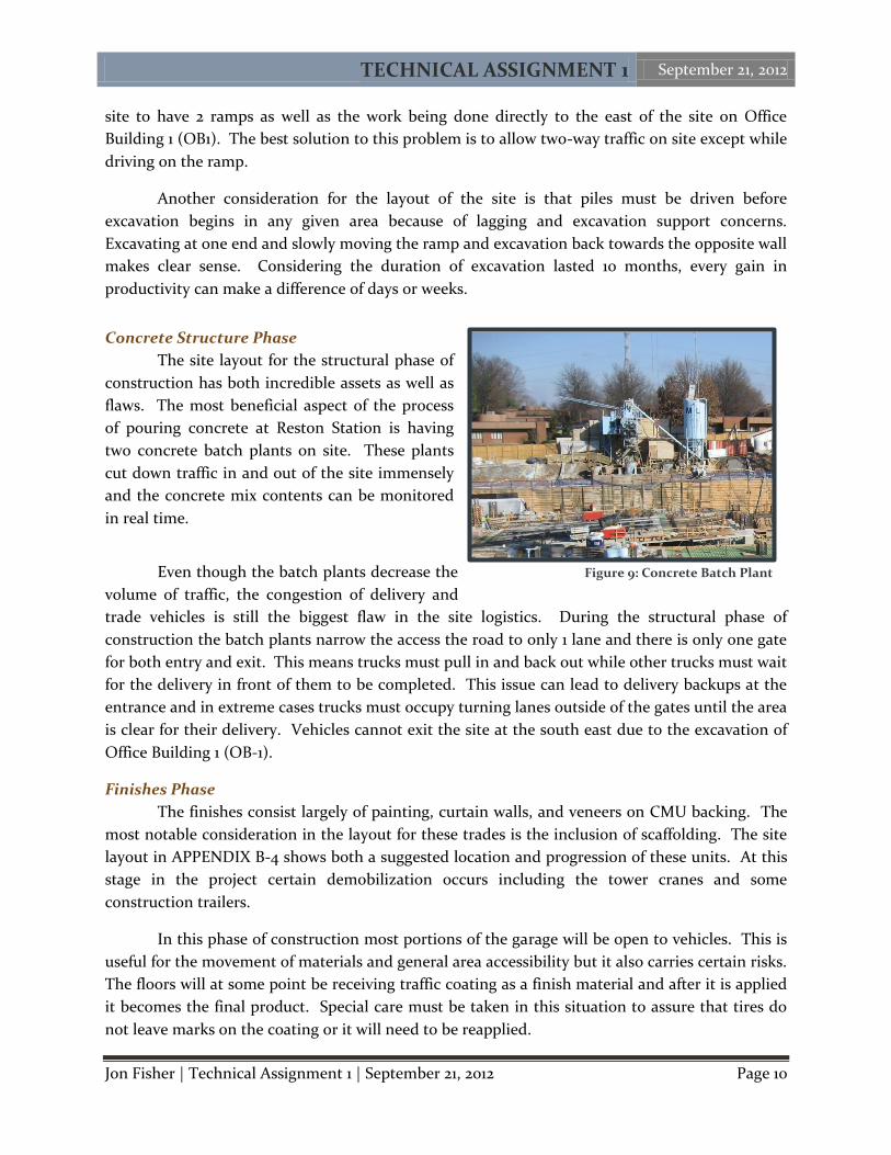
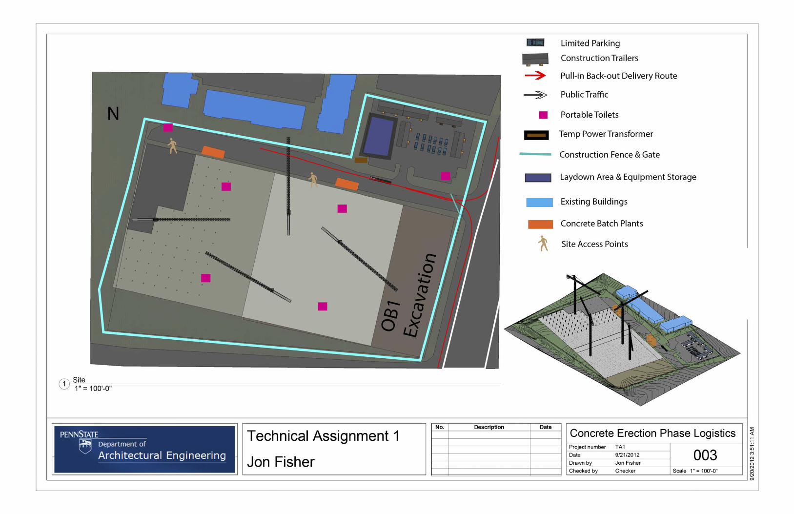
Concrete Structure Phase
The site layout for the structural phase of
construction has both incredible assets as well as
flaws. The most beneficial aspect of the process
of pouring concrete at Reston Station is having
two concrete batch plants on site. These plants
cut down traffic in and out of the site immensely
and the concrete mix contents can be monitored
in real time.
Even though the batch plants decrease the
volume of traffic, the congestion of delivery and
trade vehicles is still the biggest flaw in the site logistics. During the structural phase of
construction the batch plants narrow the access the road to only 1 lane and there is only one gate
for both entry and exit. This means trucks must pull in and back out while other trucks must wait
for the delivery in front of them to be completed. This issue can lead to delivery backups at the
entrance and in extreme cases trucks must occupy turning lanes outside of the gates until the area
is clear for their delivery. Vehicles cannot exit the site at the south east due to the excavation of
Office Building 1 (OB-1).
Finishes Phase
The finishes consist largely of painting, curtain walls, and veneers on CMU backing. The
most notable consideration in the layout for these trades is the inclusion of scaffolding. The site
layout in APPENDIX B-4 shows both a suggested location and progression of these units. At this
stage in the project certain demobilization occurs including the tower cranes and some
construction trailers.
In this phase of construction most portions of the garage will be open to vehicles. This is
useful for the movement of materials and general area accessibility but it also carries certain risks.
The floors will at some point be receiving traffic coating as a finish material and after it is applied
it becomes the final product. Special care must be taken in this situation to assure that tires do
not leave marks on the coating or it will need to be reapplied.
Figure 9: Concrete Batch Plant
TECHNICAL ASSIGNMENT 1 September 21, 2012
Jon Fisher | Technical Assignment 1 | September 21, 2012 Page 11
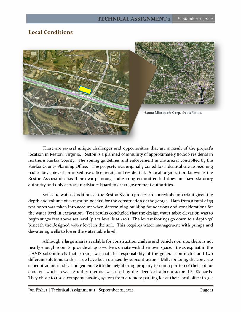
Local Conditions
There are several unique challenges and opportunities that are a result of the project’s
location in Reston, Virginia. Reston is a planned community of approximately 80,000 residents in
northern Fairfax County. The zoning guidelines and enforcement in the area is controlled by the
Fairfax County Planning Office. The property was originally zoned for industrial use so rezoning
had to be achieved for mixed use office, retail, and residential. A local organization known as the
Reston Association has their own planning and zoning committee but does not have statutory
authority and only acts as an advisory board to other government authorities.
Soils and water conditions at the Reston Station project are incredibly important given the
depth and volume of excavation needed for the construction of the garage. Data from a total of 33
test bores was taken into account when determining building foundations and considerations for
the water level in excavation. Test results concluded that the design water table elevation was to
begin at 370 feet above sea level (plaza level is at 410’). The lowest footings go down to a depth 37’
beneath the designed water level in the soil. This requires water management with pumps and
dewatering wells to lower the water table level.
Although a large area is available for construction trailers and vehicles on site, there is not
nearly enough room to provide all 400 workers on site with their own space. It was explicit in the
DAVIS subcontracts that parking was not the responsibility of the general contractor and two
different solutions to this issue have been utilized by subcontractors. Miller & Long, the concrete
subcontractor, made arrangements with the neighboring property to rent a portion of their lot for
concrete work crews. Another method was used by the electrical subcontractor, J.E. Richards.
They chose to use a company bussing system from a remote parking lot at their local office to get
©2012 Microsoft Corp. ©2012Nokia
TECHNICAL ASSIGNMENT 1 September 21, 2012
Jon Fisher | Technical Assignment 1 | September 21, 2012 Page 12
work crews to the site. Both of these solutions saves the site from a lot of car traffic and allows
the gates to be more available for daily material deliveries.
Since LEED certification was not sought after for the construction of this project recycling
was limited. The only recycling effort that was well documented and carried out was the
recycling of all extra steel. This was most evident in the recycling of rebar following concrete
forming and placement. There was not any additional tipping fees charge by the local
government beyond the charge of the service to remove the waste from the site.
Permits were an interesting challenge in the construction of the garage because of the
fast-track method of construction. Since complete drawings were not available when
construction was due to begin a building permit was approved up to the G4 level only. Later on, a
full building permit was approved midway through construction.
In addition to the considerations listed above there are some trends in the local market
and construction methods that impacted the project. For instance, due to the District of
Columbia’s building height restriction, many buildings are built from concrete to achieve small
story heights. This benefits the Reston Station project because the D.C. metro area has an
abundance of well qualified concrete sub-contractors. Miller & Long was ultimately awarded the
$30 million contract for the cast-in-place concrete and they were able to utilize their own
equipment, an experienced work force, and a large enough history of projects to utilize a high
level of financial security.
TECHNICAL ASSIGNMENT 1 September 21, 2012
Jon Fisher | Technical Assignment 1 | September 21, 2012 Page 13
Client Information The primary incentive and driving motivation for the construction of the Reston Station
civic complex is the arrival of the new Metrorail Silver Line. The Wiehle Avenue Station will be
located in between the east and west bound lanes of the Dulles Toll
Road (Rte. 267) just a few hundred feet to the west from the Wiehle
Avenue. Fairfax County has taken this opportunity to expand the
limited current parking to the north of the toll road into a mega
public parking garage. Realizing the opportunity for a commercial,
residential, and retail development, Comstock Partners Ltd. agreed
to the terms of a 99 year lease on the private development of the
above ground space of the garage. It is worth noting that
traditionally, 99 year leases are assumed to be permanent and the
99 year term is considered a formality. Comstock has been in
design development of 3 office buildings, a hotel, and an apartment
building to be built up from the plaza of the garage.
The owner team of the Reston Station project is unique due to the public-private
partnership structure between Comstock Partners and Fairfax County, Virginia. The agreement
between Comstock and Fairfax County divides the cost of construction according to the number
of public versus private parking spaces available in the garage. There are a total of 3,058 parking
spaces being constructed in the current phase of construction. Out of those spots, 2,318 (roughly
75%) are available to the public for commuting on both metro rail and metro bus services. As a
result, the approximate $92 million dollar cost of construction was divided into two portions of
roughly $70 million and $22 million to be paid by Fairfax County and Comstock respectfully. In
addition to the split cost of construction, Comstock is to pay a monthly rent on the property for
the entire duration of the lease.
The split ownership has also caused interesting issues in the phasing of the development
and construction of the garage. Fairfax County is not concerned with the building of surface
structures and requires that the garage be undisturbed throughout any future construction. This
is a challenge to Comstock’s future development of the site because traditionally shoring would
have to be placed in the garage levels to help support
the construction loads of the high rise construction
above. This applies to the current garage design
because a late structural change switched numerous
cast-in-place concrete beams on the P1 level into post
tensioned beams. This was a change that Comstock
will be fully responsible for financially.
Figure 10: Seal of the County of Fairfax
Figure 11: Logo of Comstock Partners Ltd.
TECHNICAL ASSIGNMENT 1 September 21, 2012
Jon Fisher | Technical Assignment 1 | September 21, 2012 Page 14
In order to secure the negotiated contract, DAVIS Construction, the construction
management firm, agreed to a $5 million fee holiday. This means that for the first $5 million of
change orders, there was to be no CM fee attached to the cost, the owner would simply pay the
sub-contractor’s time and material costs. With ongoing design changes at the upper levels due to
the development of above ground buildings, the cost of changes is quickly approaching the
holiday limit. Ownership is deeply concerned about these rising costs and is actively seeking
solutions through design and construction integration.
Time is of the essence for the ownership of the project. Even though the substantial
completion date and the planned arrival of the silver line are 6 months apart, gains can be made
from the Metro bus terminal in the garage immediately after the garage is opened. The schedule
has been critically delayed due to design delays. As construction catches up with current design
progress, concrete crews have been decreased in man power and coordination with MEP trades
has come to a standstill. This is of great concern to the CM because if the date of substantial
completion is missed, the owner will surly seek after liquidated damages resulting from lost
parking fees and bus ticket sales. Delivery of a finished product within the budgeted amount of
time and without going egregiously over budget will be the key to pleasing the owner
TECHNICAL ASSIGNMENT 1 September 21, 2012
Jon Fisher | Technical Assignment 1 | September 21, 2012 Page 15
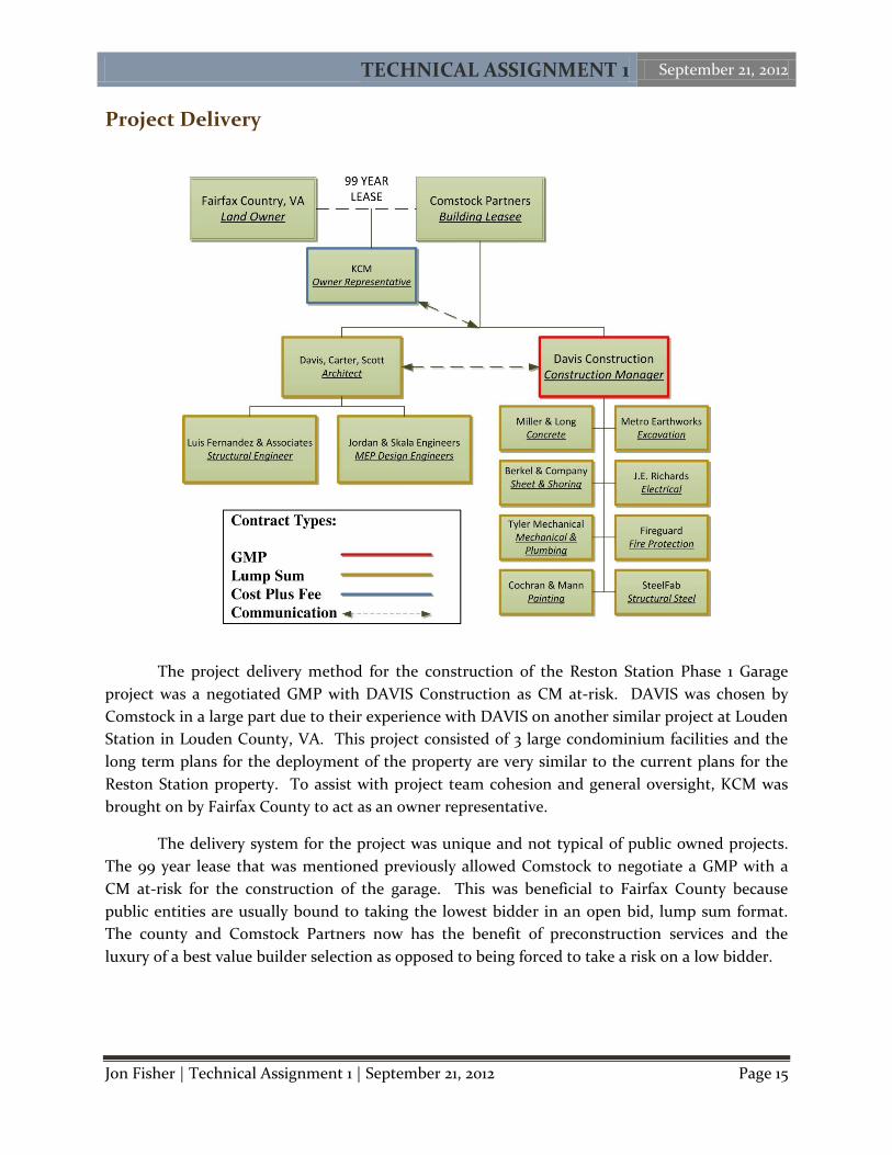
Project Delivery
The project delivery method for the construction of the Reston Station Phase 1 Garage
project was a negotiated GMP with DAVIS Construction as CM at-risk. DAVIS was chosen by
Comstock in a large part due to their experience with DAVIS on another similar project at Louden
Station in Louden County, VA. This project consisted of 3 large condominium facilities and the
long term plans for the deployment of the property are very similar to the current plans for the
Reston Station property. To assist with project team cohesion and general oversight, KCM was
brought on by Fairfax County to act as an owner representative.
The delivery system for the project was unique and not typical of public owned projects.
The 99 year lease that was mentioned previously allowed Comstock to negotiate a GMP with a
CM at-risk for the construction of the garage. This was beneficial to Fairfax County because
public entities are usually bound to taking the lowest bidder in an open bid, lump sum format.
The county and Comstock Partners now has the benefit of preconstruction services and the
luxury of a best value builder selection as opposed to being forced to take a risk on a low bidder.
Figure 12: Project Delivery Diagram
TECHNICAL ASSIGNMENT 1 September 21, 2012
Jon Fisher | Technical Assignment 1 | September 21, 2012 Page 16
The Davis GMP included a $5million fee holiday meaning that the first $5million of change
orders would not include a GC fee, this effectively the contingency. The base contract included a
GC fee of 3%. The preconstruction services up to the start of construction totaled approximately
$200,000. Insurance on the project consists of commercial general liability insurance, a builder’s
risk insurance, and a payment & performance bond. The total cost of bonds and insurance
amounts to 1.4% of the project value. Each subcontractor to DAVIS also had their own payment &
performance bonds for their respected trades. These subcontracts are all lump-sum in nature.
The biggest challenge of the delivery method has arisen in the design. Due to the fast
tracking of construction and continuously changing designs of above buildings, design firms are
running out of money in their contracts to continue proper design delivery. The issues resulting
from the delays has quickly compounded into higher prices than were originally projected in
every aspect of the project.
TECHNICAL ASSIGNMENT 1 September 21, 2012
Jon Fisher | Technical Assignment 1 | September 21, 2012 Page 17
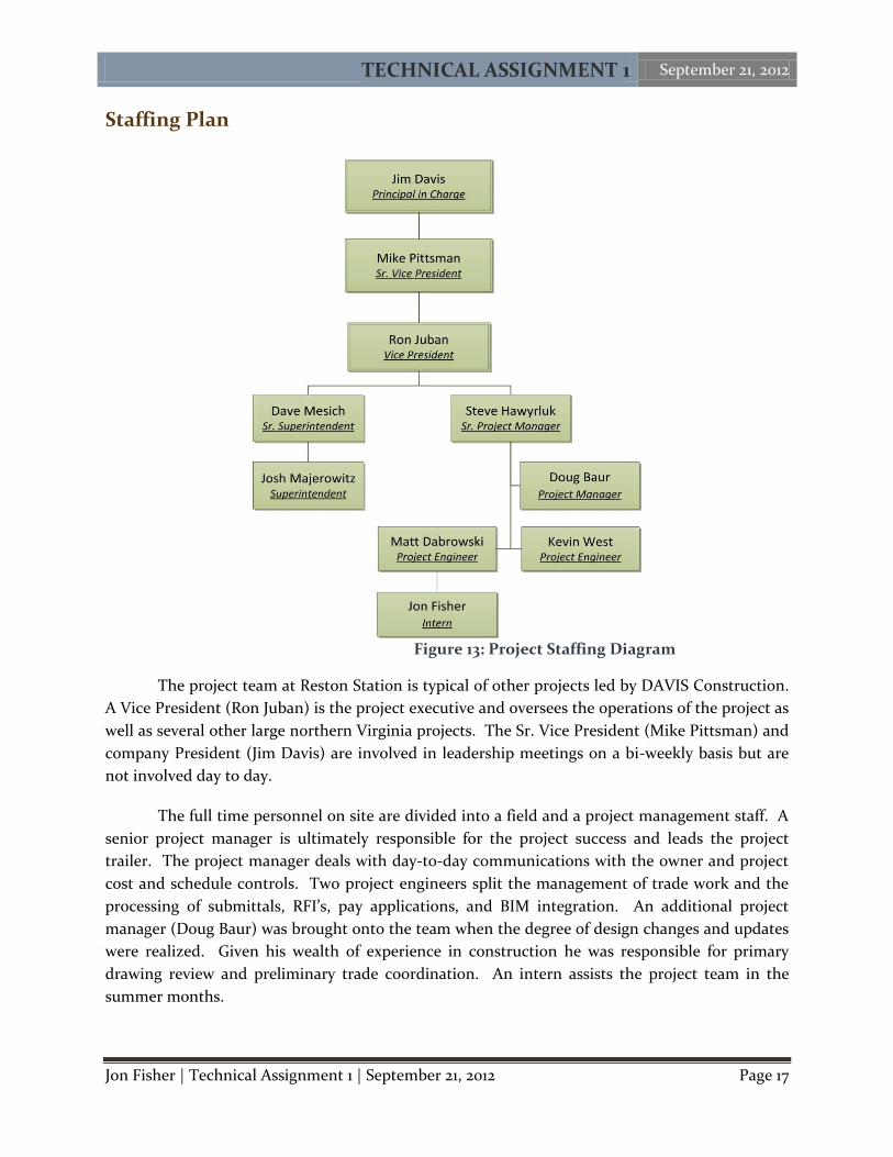
Staffing Plan
The project team at Reston Station is typical of other projects led by DAVIS Construction.
A Vice President (Ron Juban) is the project executive and oversees the operations of the project as
well as several other large northern Virginia projects. The Sr. Vice President (Mike Pittsman) and
company President (Jim Davis) are involved in leadership meetings on a bi-weekly basis but are
not involved day to day.
The full time personnel on site are divided into a field and a project management staff. A
senior project manager is ultimately responsible for the project success and leads the project
trailer. The project manager deals with day-to-day communications with the owner and project
cost and schedule controls. Two project engineers split the management of trade work and the
processing of submittals, RFI’s, pay applications, and BIM integration. An additional project
manager (Doug Baur) was brought onto the team when the degree of design changes and updates
were realized. Given his wealth of experience in construction he was responsible for primary
drawing review and preliminary trade coordination. An intern assists the project team in the
summer months.
Figure 13: Project Staffing Diagram
TECHNICAL ASSIGNMENT 1 September 21, 2012
Jon Fisher | Technical Assignment 1 | September 21, 2012 Page 18
The field staff is led by a Sr. Superintendent (Dave Mesich) who is responsible for the safe
and accurate construction of the garage. An additional superintendent and two layout engineers
assist with the construction coordination of the garage. There are two additional contracts on the
same site at the Phase 1 Garage, one is for the construction of the Office Building 1 garage,
adjacent to Phase 1, and the other is for the road construction around the site. An additional
project engineer and superintendent are on site full time for the construction of these projects.
TECHNICAL ASSIGNMENT 1 September 21, 2012
Jon Fisher | Technical Assignment 1 | September 21, 2012 Page 19
APPENDIX A
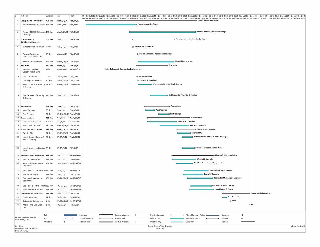
Project Summary Schedule
ID Task Name Duration Start Finish
1 Design & Pre‐Construction 705 days Mon 1/4/10 Fri 9/14/12
2 Precon Services for Owner 325 days Mon 1/4/10 Fri 4/1/11
3 Prepare 100% IFC ContractDrawings
430 days Mon 1/24/11 Fri 9/14/12
4 Procurement of Construction Services
268 days Tue 2/22/11 Thu 3/1/12
5 Subcontractor Bid Period 9 days Tue 2/22/11 Fri 3/4/11
6 General Contractor Releases Subcontracts
10 days Mon 4/4/11 Fri 4/15/11
7 Material Procurement 229 days Mon 4/18/11 Thu 3/1/12
8 Site work 197 days Mon 4/4/11 Tue 1/3/12
9 Notice To Proceed, Construction Begins
1 day Mon 4/4/11 Mon 4/4/11
10 Site Mobilization 5 days Mon 4/4/11 Fri 4/8/11
11 Clearing & Demolition 10 days Mon 4/11/11 Fri 4/22/11
12 West Excavation/Sheeting & Shoring
87 days Mon 4/18/11 Tue 8/16/11
13 East Excavation/Sheeting & Shoring
111 days Tue 8/2/11 Tue 1/3/12
14 Foundations 158 days Tue 6/14/11 Thu 1/19/12
15 West Footings 63 days Tue 6/14/11 Thu 9/8/11
16 East Footings 72 days Wed 10/12/11 Thu 1/19/12
17 Superstructure 265 days Fri 7/8/11 Thu 7/12/12
18 West G7‐P2 Concrete 188 days Fri 7/8/11 Tue 3/27/12
19 East G7‐P3 Concrete 187 days Wed 10/26/11 Thu 7/12/12
20 Above Ground Enclosure 118 days Wed 3/28/12 Fri 9/7/12
21 Exterior CMU 87 days Wed 3/28/12 Thu 7/26/12
22 Install Granite Cladding & Metal Paneling
72 days Wed 5/9/12 Thu 8/16/12
23 Install Louvers and CurtainWalls
88 days Wed 5/9/12 Fri 9/7/12
24 Finishes & MEP Installation 265 days Tue 2/14/12 Mon 2/18/13
25 West MEP Rough‐in 153 days Tue 2/14/12 Thu 9/13/12
26 West Install Mechanical Equipment
107 days Tue 3/20/12 Wed 8/15/12
27 West Paint & Traffic Coatin157 days Tue 5/29/12 Wed 1/2/13
28 East MEP Rough‐in 128 days Tue 5/22/12 Thu 11/15/12
29 East Install Mechanical Equipment
166 days Wed 6/27/12 Wed 2/13/13
30 East Paint & Traffic Coating133 days Thu 7/26/12 Mon 1/28/13
31 Plaza Finishes & Fit‐out 158 days Thu 7/12/12 Mon 2/18/13
32 Inspections & Occupancy 173 days Tue 5/7/13 Thu 1/2/14
33 Final Inspections 31 days Tue 5/7/13 Tue 6/18/13
34 Substantial Completion 1 day Wed 7/17/13 Wed 7/17/13
35 Metro Silver Line Goes Live
1 day Thu 1/2/14 Thu 1/2/14
Design & Pre‐Construction
Precon Services for Owner
Prepare 100% IFC Contract Drawings
Procurement of Construction Services
Subcontractor Bid Period
General Contractor Releases Subcontracts
Material Procurement
Site work
Notice To Proceed, Construction Begins 4/4
Site Mobilization
Clearing & Demolition
West Excavation/Sheeting & Shoring
East Excavation/Sheeting & Shoring
Foundations
West Footings
East Footings
Superstructure
West G7‐P2 Concrete
East G7‐P3 Concrete
Above Ground Enclosure
Exterior CMU
Install Granite Cladding & Metal Paneling
Install Louvers and Curtain Walls
Finishes & MEP Installation
West MEP Rough‐in
West Install Mechanical Equipment
West Paint & Traffic Coating
East MEP Rough‐in
East Install Mechanical Equipment
East Paint & Traffic Coating
Plaza Finishes & Fit‐out
Inspections & Occupancy
Final Inspections
7/17
1/2
Dec Jan FebMar AprMay Jun Jul Aug Sep Oct Nov Dec Jan FebMar AprMay Jun Jul Aug Sep Oct Nov Dec Jan FebMar AprMay Jun Jul Aug Sep Oct Nov Dec Jan FebMar AprMay Jun Jul Aug Sep Oct Nov Dec Jan FebMar AprMay Jun Jul Aug Sep Oct Nov Dec Jan FebMar AprMa009 Qtr 1, 2010 Qtr 2, 2010 Qtr 3, 2010 Qtr 4, 2010 Qtr 1, 2011 Qtr 2, 2011 Qtr 3, 2011 Qtr 4, 2011 Qtr 1, 2012 Qtr 2, 2012 Qtr 3, 2012 Qtr 4, 2012 Qtr 1, 2013 Qtr 2, 2013 Qtr 3, 2013 Qtr 4, 2013 Qtr 1, 2014 Qtr 2, 2014 Qtr 3, 2014 Qtr 4, 2014 Qtr 1, 2015 Qtr 2,
Task
Split
Milestone
Summary
Project Summary
External Tasks
External Milestone
Inactive Task
Inactive Milestone
Inactive Summary
Manual Task
Duration‐only
Manual Summary Rollup
Manual Summary
Start‐only
Finish‐only
Deadline
Progress
Jon FisherBuilding Summary ScheduleDate: 9/17/2012
Reston Station Phase 1 GarageReston, VA
Advisor: Dr. Leicht
Project: Summary ScheduleDate: Thu 9/20/12

TECHNICAL ASSIGNMENT 1 September 21, 2012
Jon Fisher | Technical Assignment 1 | September 21, 2012 Page 21
APPENDIX B-1
Existing Site Conditions

TECHNICAL ASSIGNMENT 1 September 21, 2012
Jon Fisher | Technical Assignment 1 | September 21, 2012 Page 23
APPENDIX B-2
Excavation Phase Site Plan

TECHNICAL ASSIGNMENT 1 September 21, 2012
Jon Fisher | Technical Assignment 1 | September 21, 2012 Page 25
APPENDIX B-3
Structure Phase Site Plan
TECHNICAL ASSIGNMENT 1 September 21, 2012
Jon Fisher | Technical Assignment 1 | September 21, 2012 Page 27
APPENDIX B-4
Finishes & Enclosure Phase
Site Plan

TECHNICAL ASSIGNMENT 1 September 21, 2012
Jon Fisher | Technical Assignment 1 | September 21, 2012 Page 29
APPENDIX C-1
Square Foot Cost Estimate Data
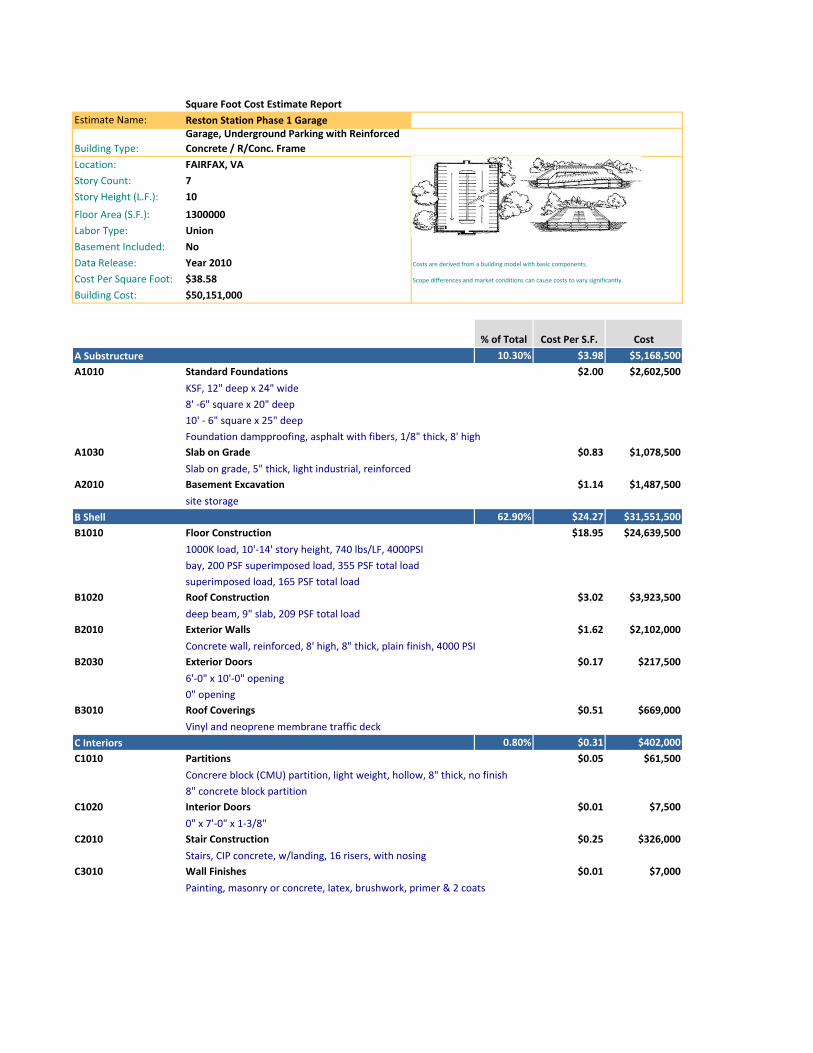
Square Foot Cost Estimate ReportEstimate Name: Reston Station Phase 1 Garage
Building Type:Garage, Underground Parking with Reinforced Concrete / R/Conc. Frame
Location: FAIRFAX, VAStory Count: 7Story Height (L.F.): 10
Floor Area (S.F.): 1300000Labor Type: UnionBasement Included: No Data Release: Year 2010Cost Per Square Foot: $38.58 Building Cost: $50,151,000
% of Total Cost Per S.F. Cost10.30% $3.98 $5,168,500
A1010 Standard Foundations $2.00 $2,602,500
A1030 Slab on Grade $0.83 $1,078,500
A2010 Basement Excavation $1.14 $1,487,500
62.90% $24.27 $31,551,500 B1010 Floor Construction $18.95 $24,639,500
B1020 Roof Construction $3.02 $3,923,500
B2010 Exterior Walls $1.62 $2,102,000
B2030 Exterior Doors $0.17 $217,500
B3010 Roof Coverings $0.51 $669,000
0.80% $0.31 $402,000 C1010 Partitions $0.05 $61,500
C1020 Interior Doors $0.01 $7,500
C2010 Stair Construction $0.25 $326,000
C3010 Wall Finishes $0.01 $7,000
8' ‐6" square x 20" deep
Costs are derived from a building model with basic components.
Scope differences and market conditions can cause costs to vary significantly.
A Substructure
KSF, 12" deep x 24" wide
0" opening
10' ‐ 6" square x 25" deepFoundation dampproofing, asphalt with fibers, 1/8" thick, 8' high
Slab on grade, 5" thick, light industrial, reinforced
site storageB Shell
1000K load, 10'‐14' story height, 740 lbs/LF, 4000PSIbay, 200 PSF superimposed load, 355 PSF total loadsuperimposed load, 165 PSF total load
deep beam, 9" slab, 209 PSF total load
Concrete wall, reinforced, 8' high, 8" thick, plain finish, 4000 PSI
6'‐0" x 10'‐0" opening
Vinyl and neoprene membrane traffic deckC Interiors
Concrere block (CMU) partition, light weight, hollow, 8" thick, no finish8" concrete block partition
0" x 7'‐0" x 1‐3/8"
Stairs, CIP concrete, w/landing, 16 risers, with nosing
Painting, masonry or concrete, latex, brushwork, primer & 2 coats
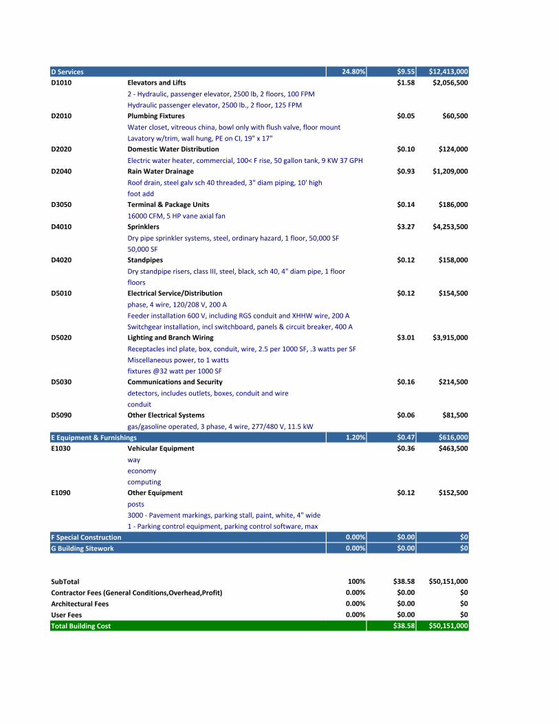
24.80% $9.55 $12,413,000 D1010 Elevators and Lifts $1.58 $2,056,500
D2010 Plumbing Fixtures $0.05 $60,500
D2020 Domestic Water Distribution $0.10 $124,000
D2040 Rain Water Drainage $0.93 $1,209,000
D3050 Terminal & Package Units $0.14 $186,000
D4010 Sprinklers $3.27 $4,253,500
D4020 Standpipes $0.12 $158,000
D5010 Electrical Service/Distribution $0.12 $154,500
D5020 Lighting and Branch Wiring $3.01 $3,915,000
D5030 Communications and Security $0.16 $214,500
D5090 Other Electrical Systems $0.06 $81,500
1.20% $0.47 $616,000 E1030 Vehicular Equipment $0.36 $463,500
E1090 Other Equipment $0.12 $152,500
0.00% $0.00 $0 0.00% $0.00 $0
100% $38.58 $50,151,000 0.00% $0.00 $0 0.00% $0.00 $0 0.00% $0.00 $0
$38.58 $50,151,000
Lavatory w/trim, wall hung, PE on CI, 19" x 17"
D Services
2 ‐ Hydraulic, passenger elevator, 2500 lb, 2 floors, 100 FPMHydraulic passenger elevator, 2500 lb., 2 floor, 125 FPM
Water closet, vitreous china, bowl only with flush valve, floor mount
Receptacles incl plate, box, conduit, wire, 2.5 per 1000 SF, .3 watts per SF
Electric water heater, commercial, 100< F rise, 50 gallon tank, 9 KW 37 GPH
Roof drain, steel galv sch 40 threaded, 3" diam piping, 10' highfoot add
16000 CFM, 5 HP vane axial fan
Dry pipe sprinkler systems, steel, ordinary hazard, 1 floor, 50,000 SF50,000 SF
Dry standpipe risers, class III, steel, black, sch 40, 4" diam pipe, 1 floorfloors
phase, 4 wire, 120/208 V, 200 AFeeder installation 600 V, including RGS conduit and XHHW wire, 200 ASwitchgear installation, incl switchboard, panels & circuit breaker, 400 A
1 ‐ Parking control equipment, parking control software, max
Miscellaneous power, to 1 wattsfixtures @32 watt per 1000 SF
detectors, includes outlets, boxes, conduit and wireconduit
gas/gasoline operated, 3 phase, 4 wire, 277/480 V, 11.5 kWE Equipment & Furnishings
wayeconomycomputing
posts3000 ‐ Pavement markings, parking stall, paint, white, 4" wide
Total Building Cost
F Special ConstructionG Building Sitework
SubTotalContractor Fees (General Conditions,Overhead,Profit)Architectural FeesUser Fees
TECHNICAL ASSIGNMENT 1 September 21, 2012
Jon Fisher | Technical Assignment 1 | September 21, 2012 Page 31
APPENDIX C-2
Assembly Cost Estimate Data
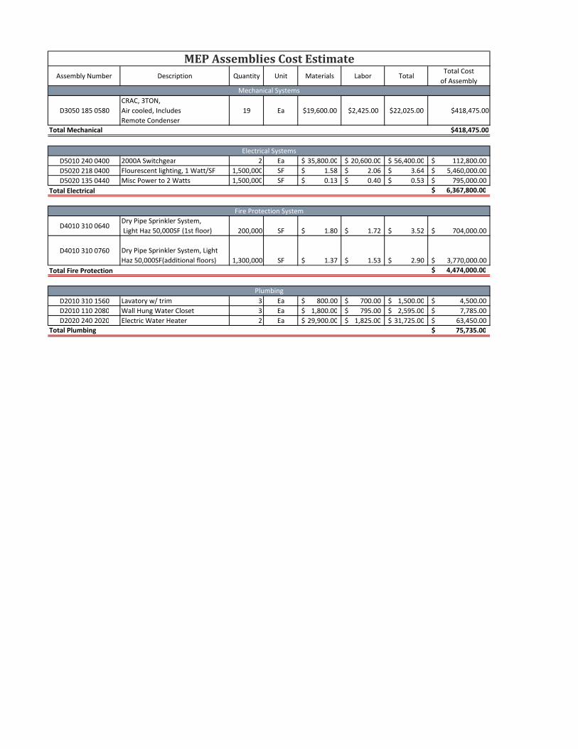
Assembly Number Description Quantity Unit Materials Labor TotalTotal Costof Assembly
D3050 185 0580CRAC, 3TON,Air cooled, IncludesRemote Condenser
19 Ea $19,600.00 $2,425.00 $22,025.00 $418,475.00
Total Mechanical $418,475.00
D5010 240 0400 2000A Switchgear 2 Ea 35,800.00$ 20,600.00$ 56,400.00$ 112,800.00$ D5020 218 0400 Flourescent lighting, 1 Watt/SF 1,500,000 SF 1.58$ 2.06$ 3.64$ 5,460,000.00$ D5020 135 0440 Misc Power to 2 Watts 1,500,000 SF 0.13$ 0.40$ 0.53$ 795,000.00$
Total Electrical 6,367,800.00$
D4010 310 0640Dry Pipe Sprinkler System, Light Haz 50,000SF (1st floor) 200,000 SF 1.80$ 1.72$ 3.52$ 704,000.00$
D4010 310 0760 Dry Pipe Sprinkler System, Light Haz 50,000SF(additional floors) 1,300,000 SF 1.37$ 1.53$ 2.90$ 3,770,000.00$
Total Fire Protection 4,474,000.00$
D2010 310 1560 Lavatory w/ trim 3 Ea 800.00$ 700.00$ 1,500.00$ 4,500.00$ D2010 110 2080 Wall Hung Water Closet 3 Ea 1,800.00$ 795.00$ 2,595.00$ 7,785.00$ D2020 240 2020 Electric Water Heater 2 Ea 29,900.00$ 1,825.00$ 31,725.00$ 63,450.00$
Total Plumbing 75,735.00$
Plumbing
MEPAssembliesCostEstimate
Mechanical Systems
Fire Protection System
Electrical Systems


