Technical Assistance Consultant’s Report This consultant’s report does not necessarily reflect the views of ADB or the Government concerned, and ADB and the Government cannot be held liable for its contents. (For project preparatory technical assistance: All the views expressed herein may not be incorporated into the proposed project’s design. Project Number: 34304 December 2006 NEPAL: Kathmandu Valley Water Distribution, Sewerage, and Urban Development Project (Financed by: Technical Assistance Special Fund, Government of Denmark and the Cooperation Fund for the Water Sector) Prepared by: GHD Pty Ltd., Australia in assn with Integrated Consultants Nepal (ICON) Pvt. Lt. Nepal For the Ministry of Physical Planning and Works
Transcript
Technical Assistance Consultant’s Report
This consultant’s report does not necessarily reflect the views of ADB or the Government concerned, and ADB and the Government cannot be held liable for its contents. (For project preparatory technical assistance: All the views expressed herein may not be incorporated into the proposed project’s design.
Project Number: 34304 December 2006
NEPAL: Kathmandu Valley Water Distribution, Sewerage, and Urban Development Project (Financed by: Technical Assistance Special Fund, Government of Denmark and the Cooperation Fund for the Water Sector)
Prepared by:
GHD Pty Ltd., Australia in assn with Integrated Consultants Nepal (ICON) Pvt. Lt. Nepal
For the Ministry of Physical Planning and Works
Error! Unknown document property name.
Government of Nepal
Ministry of Physical Planning & Works
Kathmandu Upatyaka Khanepani Limited
KATHMANDU VALLEY WATER SUPPLY & WASTEWATER SYSTEM IMPROVEMENT
(PPTA 4893 – NEP)
KUKL Water Supply Service Sub-Zone A-4.2
Distribution Network Improvement (DNI)
Kalo Pool Pilot Area
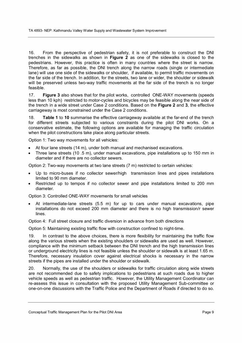
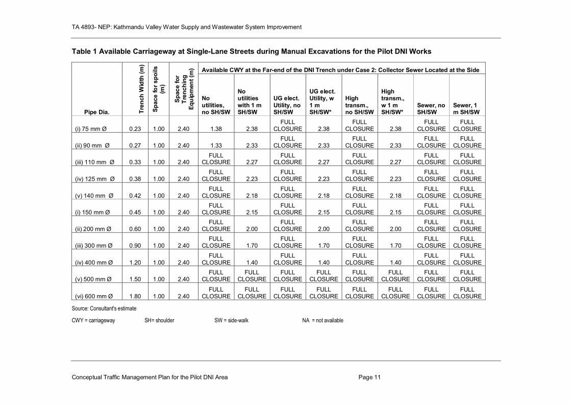
DETAILED DESIGN REPORT (FINAL)
MAY 2010
ADB
TA 4893 –NEP: Kathmandu Valley Water Supply & Wastewater System Improvement DNI Detail Design Report
DNI Pilot Area Detailed Design Report_Final Page i
KUKL Water Supply Service Sub-Zone A-4.2
Distribution Network Improvement (DNI) - Kalo Pool Pilot Area
1.1 General Project Background ................................................................................................... 1 1.2 Project Objective ..................................................................................................................... 1 1.3 Introduction of the Project Area .............................................................................................. 2 1.4 Structure of Report ................................................................................................................. 3
2. Existing Water Supply and Sanitation Scenario ........................................................................... 4
2.1 Existing Supply and Consumption .......................................................................................... 4 2.2 Operating Period ..................................................................................................................... 5 2.3 Customers .............................................................................................................................. 5 2.4 Tariff ....................................................................................................................................... 5
3. Design Standards and Approach ................................................................................................. 5
3.1 General Approach ................................................................................................................... 5 3.2 Selecting the Pilot DNI Area ................................................................................................... 6 3.3 Benefits and Impacts of DNI in the Pilot Area ......................................................................... 8
3.3.1 Uniformity and Equity of Service in the Pilot Area ......................................................................... 8 3.3.2 Reduction in Unaccounted for Water (UFW) / Non-Revenue Water (NRW) ............................... 8 3.3.3 Services to the poor and under privileged ..................................................................................... 9 3.3.4 Impact in Post Melamchi Scenario ................................................................................................. 9
3.4 Design Parameters and Criteria .............................................................................................. 9 3.4.1 Background...................................................................................................................................... 9
3.4.2 Design Period ......................................................................................................................... 9 3.4.3 Demographic Characteristics .................................................................................................. 9 3.4.4 Growth Trend and Limitation................................................................................................. 10 3.4.5 Population Projection ............................................................................................................ 10 3.5 Engineering Design and Approach ....................................................................................... 14
4. Survey and Investigations ......................................................................................................... 14
5. Proposed Distribution Network Improvement .......................................................................... 16
5.1 Distribution Network Configuration ....................................................................................... 16 5.2 Basic DNI Concepts and Approach ...................................................................................... 16 5.3 Demand Projection and Allocation ........................................................................................ 17 5.4 Network Modeling and Design .............................................................................................. 17
Distribution Mains/Lines ................................................................................................ 19 Chambers 19 Bulk Meters and other Valve Chambers ......................................................................... 19 Pipe Valve Chambers ..................................................................................................... 20 Washout Chambers ....................................................................................................... 20 Air Valve Chamber ......................................................................................................... 20
TA 4893 –NEP: Kathmandu Valley Water Supply & Wastewater System Improvement DNI Detail Design Report
DNI Pilot Area Detailed Design Report_Final Page ii
Water Revenue Meter ................................................................................................... 20 House Connection .......................................................................................................... 20
6.1 Capital Cost of Water Supply System ................................................................................... 21 7. Socio-economic Characteristics of Pilot Area ............................................................................ 23
8. Environmental Assessment and Considerations ........................................................................ 31
Soil Erosion and Slope Stability due to Excavation .......................................................... 31 Change in River Hydrology and Morphology ................................................................... 32 Water and Land Pollution............................................................................................... 32 Pollution due to Air, Noise and Vibrations ...................................................................... 32 Compensation and Rehabilitation as per the Resettlement Plan (RP) ............................. 33 Reinstatement of Damaged Community Services and Infrastructure .............................. 33 Influx of Outside Workforce, Money and Unwanted Activities ....................................... 33 Health and Safety........................................................................................................... 34 Occupational Health and Safety (OHS) ........................................................................... 34 Community Health and Safety ........................................................................................ 34
9. Procurement and Implementation Schedule ............................................................................. 36
10. Conclusion and Recommendation ........................................................................................ 37
TA 4893 –NEP: Kathmandu Valley Water Supply & Wastewater System Improvement DNI Detail Design Report
DNI Pilot Area Detailed Design Report_Final Page iii
Appendices
Appendix 1: Water Demand Calculations
Appendix 2: Pipeline Hydraulic Design
Appendix 3: Engineer’s Cost Estimates
Appendix 4: Quantity Estimations
Appendix 5: Unit Rate Analysis
Appendix 6: Traffic Management Plan
TA 4893 –NEP: Kathmandu Valley Water Supply & Wastewater System Improvement DNI Detail Design Report
DNI Pilot Area Detailed Design Report_Final Page iv
List of Acronyms
ADB Asian Development Bank
BOQ Bills of Quantities
DI Ductile Iron
DNI Distribution Network Improvement
EIA Environmental Impact Assessment
GI Galvanized Iron
GON Government of Nepal
HDPE High Density Polyetheleyene
ICB International Competitive Bidding
IFB Information for Bidders
ITB Instruction to Bidders
JBIC Japan Bank for International Development
KMC Kathmandu Metropolitan City
KUKL Kathmandu Upatkya Khanepani Limited
KVWSMB Kathmandu Valley Water Supply Management Board
MLD Million Liters per Day
MUTM Modified Universal Transverse Projection
MWSP Melamchi Water Supply Project
NRW Non-revenue Water
NTFP non-timber forest products
NWSC Nepal Water Supply Corporation
OHS Occupational Health and Safety
OHT Overhead Tank
PID Project Implementation Directorate
PPE Personal Protection Equipment
RCC Reinforced Cement Concrete
RP Resettlement Plan
SDP Sector Development Programme
UFW Unaccounted For Water
uPVC Unplasticized Polyvinyl chloride
TA 4893 –NEP: Kathmandu Valley Water Supply & Wastewater System Improvement DNI Detail Design Report
Page 1
KUKL Water Supply Service Sub-Zone A-4.2
Distribution Network Improvement (DNI) - Kalo Pool Pilot Area
Detailed Design Report
1. Introduction
1.1 General Project Background
1 Kathmandu Valley is currently suffering from chronic water shortages and inefficient service delivery. To improve the present conditions of water supply and wastewater services in Kathmandu Valley, the Government of Nepal (GoN), with the assistance of several development partners, has embarked on a two-pronged improvement strategy that includes capital investments for infrastructure development, i.e. supply augmentation and system improvement and institutional reforms. In order to assist GoN in this endeavour, Asian Development Bank (ADB) has provided three loans for Melamchi Water Supply Project (MWSP) and Kathmandu Valley Water Services Sector Development Program (SDP) covering both infrastructure investment and institutional reforms. Other external development partners, such as the Japan Bank for International Cooperation (JBIC), the Nordic Development Fund, etc, are also assisting GoN.
2 The GoN has recently achieved substantial progress in institutional reforms in the water services sector of Kathmandu Valley and established an independent regulatory commission for regulating the water tariffs, and set up an autonomous water operator company under the Company Act. The Kathmandu Upatyaka Khanepani Limited (KUKL) is responsible for operating the assets under lease and license from Kathmandu Valley Water Supply Management Board (KVWSMB).
3 KUKL took over the operations of Kathmandu Valley water services on 13 February 2008 from the previous public water utility operator Nepal Water Supply Corporation (NWSC). The present ADB TA 4893-NEP: Preparing the Kathmandu Valley Water Distribution, Sewerage, and Urban Development Project has the objective to provide support for GoN in preparing a project to continue the urban infrastructure development in the Kathmandu Valley subsequent to three ongoing ADB loans.
4 Selection of the Pilot area for the distribution network improvements (DNI) has been done by focusing on those areas which had representative problems of the water distribution network in Kathmandu valley. The issues related to quantity, quality, and reliability of water supply. The pilot area reflects the technical complexity and magnitude of financial resources required for making distribution network improvements in other areas. The pilot area is to be used to develop methods and procedures for solving common distribution network problems in other areas of the water supply system.
1.2 Project Objective
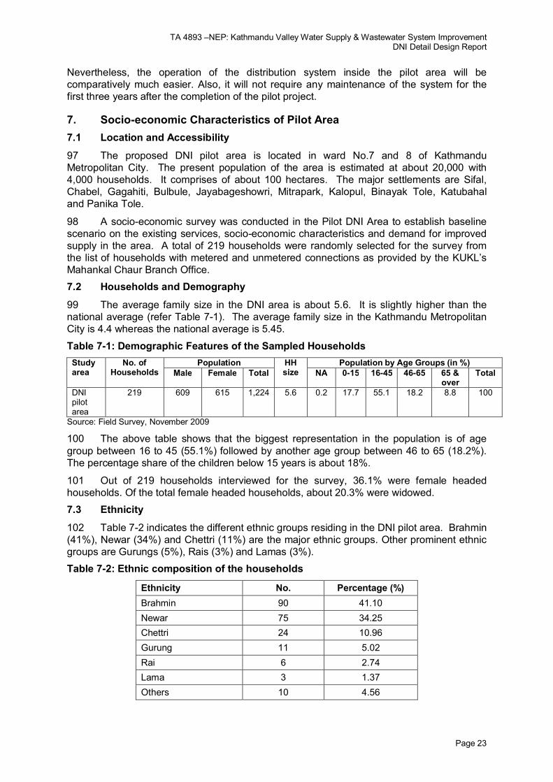
5 The PPTA TOR envisaged identifying three priority areas for implementation of DNI works, taking into account the existing studies on the water supply and distribution system in Kathmandu Valley and the detailed design report for the DNI demonstration project at Baneshwor under Loan 1820-NEP: MWSP Subproject-2. The selection of the DNI pilot area included assessing the water availability, network hydrology and water pressure in target areas. The main objective of the pilot area is to optimize the existing water supply and increase the availability of potable water for distribution. According to KUKL’s license conditions, all registered KUKL customers should have equitable and regular access to potable water with the aim of eventually providing a 24-hours per day supply.
TA 4893 –NEP: Kathmandu Valley Water Supply & Wastewater System Improvement DNI Detail Design Report
Page 2
6 Under the PPTA, out of 3 identified priority areas, one area was to be selected as the pilot area for which detailed designs and contract bid documents would be prepared. The PPTA consultants in close consultation with KUKL identified four priority areas for detail design of DNI works consideration, taking into account the followings:
existing studies on the water supply and distribution system in Kathmandu Valley
detailed design report for the DNI demonstration project at Baneshwor
reports by the consultants engaged under ADB-assisted projects
condition of water availability, network hydraulics, water pressure in target areas
contribution to achieving the project’s overall objectives
assessment on the implementability of immediate physical works
7 As per the requirements of the TOR, the detailed design should include:
description on the area and scope of works
technical specifications
bill of quantities
drawings
bid documents for implementation of designed works
1.3 Introduction of the Project Area
8 Of the four water supply service areas identified, the Kalopool area, partly in KMC Ward 7 and Ward 8 (refer Figure 1-1: Location Plan), was selected as being the most representative and appropriate area for the DNI pilot. The area is bounded by the Ring Road from Chabel Junction to Gaushala Junction in the east and the Dhobhi Khola in the west. The Ring Road near Gopi Krishna to Chabel Junction forms the northern boundary of the Pilot DNI Area, while the Rato Pool – Gaushala Road forms the southern boundary. The total area covered by the Pilot DNI Area is about 100 hectares of urban land, which is densely populated and developing. The typical problems exhibited in the area include:
Little equity in water supply; some properties get very good supply with good pressure for 6-7 hours, while others get only 1 to 2 hours supply every fourth or fifth day with very poor pressure;
Very high water leakage and losses in the area having good supply;
No control mechanism for isolating the service area for maintenance;
Multiple house connections to a trunk water supply main;
Old and undersized water distribution mains;
No operational fire hydrants;
Long, multiple house connection pipe work;
Areas of poor water supply service (in most of the pilot area);
Few operational consumer meters.
TA 4893 –NEP: Kathmandu Valley Water Supply & Wastewater System Improvement DNI Detail Design Report
Page 3
Figure 1-1: Location Plan
1.4 Structure of Report
9 The detailed design report for the Pilot DNI area in Kalopul area is structured to provide all necessary project rationale, basis and approach for detailed design, drawings and estimates and other relevant details needed in implementing the proposed DNI works. The table below gives a brief outline of the various chapters and its content:
Table 1-1: Structure of the Report
Chapter Description
1. Introduction General background, objective and description of the project area.
2. Existing Water Supply and Sanitation Scenario
Description of existing water supply situation, details on customer, consumption and tariff in the area.
3. Design Standards and Approach
General design approach, process of selecting the pilot area, design criteria adopted including population projection and water demand analysis.
4. Survey and Investigations
Method adopted for engineering survey, preparation of survey and base maps, and verification of existing pipeline network.
5. Proposed Distribution Network Improvement
Description of basic DNI concepts and approach, nodal demand projection and allocation, network modelling and design. Description of project components – primarily distribution mains, house connections, public stand posts and appurtenances.
6. Project Cost Estimation
Capital Cost of Water Supply System, Unit Rate Analysis, Quantity and Cost Estimations and O & M Cost of Water Supply System
7. Social Assessment and Profile of Pilot Area
Description of the social features of the area including settlement pattern, infrastructure facilities, population, education, economic characteristics, hygiene and sanitation, gender issues and land acquisition and resettlement requirements.
8. Environmental Assessment of Pilot Area
Description of environmental baseline scenario, potential impacts and proposed mitigation approaches to be adopted during implementation is described.
9. Procurement and Implementation Schedule
Procurement requirements including procedures for efficient implementation. A implementation schedule including maintenance of access, services and utility coordination.
10. Conclusion and Recommendation
Major conclusions derived from the assessment and design process and recommendations plus any risks associated with the project.
TA 4893 –NEP: Kathmandu Valley Water Supply & Wastewater System Improvement DNI Detail Design Report
Page 4
2. Existing Water Supply and Sanitation Scenario
10 The Kalopool area located partly in KMC Wards 7 and 8 is a typical densely populated and still developing urban area within the Kathmandu Metro Zone. The area is a very representative and appropriate area for the DNI pilot as it exhibits a number of characteristics typical of the water delivery services in Kathmandu. In some parts of the Pilot Area, supply is good because the main trunk main conveying water for the core area of Kathmandu passes through the Pilot Area and residents are directly tapping from such mains. While in other parts, the supply is poor with supply only every third or fourth day. There is high leakage and wastage directly from pipe mains and also house connections. Metered connections are generally not functioning and people resort to direct pumping of water from the mains to augment their supplies. Other related amenities like fire hydrants are either non-existent or totally vandalized.
2.1 Existing Supply and Consumption
11 The existing water supply service in the Pilot DNI Area is varies (Refer Fig.3: Existing Water Pressure Diagram), as with most of the Kathmandu Metro Zone. Most of the residents get piped water supply for nearly one hour every fifth day with the exception of the residents living along the main supply mains and having direct (sometimes illegal) connections from such mains, who get regular water supply with good pressure. Over 90% of the residents have piped water supply connections in the area. Most of such households also have secondary water sources like hand pumps, dug well or other such facilities to supplement their daily requirements. In addition, some households also supplement their drinking water requirements through the use of private tankers and bottled water. As per the survey done in the Pilot DNI Area, the average per capita consumption in the wet season is more than 80 liters while in the dry season this decreases to about 68 liters.
Figure 2-1: Existing water pressure diagram
TA 4893 –NEP: Kathmandu Valley Water Supply & Wastewater System Improvement DNI Detail Design Report
Page 5
2.2 Operating Period
12 The operation of distribution system in the pilot area has been carried out by dividing the area into four categories. They are:
Category A: Area adjacent to the main road from Chabahil Chowk to Siphal along which transmission main of 600 mm diameter exists but with the exception of low lying area near Kalopool.
Category B: Low lying areas near Kalopool
Category C: Area adjacent to the Ring Road
Category D: Areas located in the west of the main Chabahil-Siphal Road and areas near to the Bhatkeko Pool (west of Chabahil Ganessthan)
13 Areas mentioned in the first category get supply when the 600mm diameter main valve at Chabahil Chowk is opened to supply water to downstream areas of the city, mainly to Naxal, Kamal Pokhari, etc. via Siphal. The area gets supply for one to two hours at low pressure of about 1 meter. The valve at Chabahil Chowk is kept open for seven hours (from 12 to 7 in the evening).
14 Areas included in the second category, however, get very good supply of water (with pressure in between 2-3 meters for nearly seven hours (while the main valve is open).
15 Though located in the same area, customers living in the area of the third category get less supply of water. These areas are supplied through a 300mm diameter pipe for 4 hours (from 12 to 4) every fourth day. Pipelines of bigger diameter pipes (600 mm and 500mm) running through the Ring Road are kept separate for boosting supply to the New Road and Baneswor areas, respectively. Another 600mm diameter valve, also located at Chabahil Chowk, is kept open for nine hours (from 2 am to 11 am) for this purpose.
16 The fourth category area is the worst, which is supplied from an old 125mm diameter pipeline. This area gets water supply for only one hour every fifth day.
2.3 Customers
17 The pilot area is inhabited by heterogeneous groups of people not only from socio-economic aspects but also from the level of services they are presently receiving from KUKL and amount of money that is being paid in return. About 95% of the private connections so far connected with the system are of ½“ size and 70% are metered.
2.4 Tariff
18 The existing KUKL tariff rates are also applicable in the Pilot DNI Area. Tariffs paid to KUKL by customers per month ranges from Rs.55 minimum for the first 10,000 liters and Rs. 17.50 per 1000 liters thereafter for metered ½” inch household connections and Rs.432 for unmetered connections, excluding additional charge for wastewater connection at the rate of 50 percent wherever sewer lines are available.
3. Design Standards and Approach
3.1 General Approach
19 In depth consultation was undertaken with the KUKL Branch Managers in selecting representative service areas. The following broad criteria were used in the process.
Area can be easily hydraulically isolated and provided with dedicated bulk metered feed main.
Represents average population density of KUKL service area.
Population of the area about 20,000 and about 100 hectare.
TA 4893 –NEP: Kathmandu Valley Water Supply & Wastewater System Improvement DNI Detail Design Report
Page 6
Minimal or no crossing of distribution pipes across natural and political boundaries.
Easy to understand spatial distribution of water demand and non-revenue water for Branch office of KUKL.
Presently has areas under-served by piped water supply and has a high community demand for improvement.
Area can be served by gravity system (not pumped or booster).
Preferably with existing OHT or government land available for service OHT.
Area has heterogeneous socio-economic group including average representation of poor families.
Area has good drainage topography and could easily be provided with sewerage pipes and sewerage treatment package (if land is available) or septic tanks and drainage.
3.2 Selecting the Pilot DNI Area
20 Following a number of meetings with senior KUKL managers 4 rather than 3 areas were identified for further consideration. Figure 3-1 shows the 4 identified areas, which were further assessed in order to recommend the final selected pilot area. Table 3-1 gives a summary of the four areas’ evaluation.
Figure 3-1: Identified Areas for Pilot Project
TA 4893 –NEP: Kathmandu Valley Water Supply & Wastewater System Improvement DNI Detail Design Report
Page 7
21 The service area of the Pilot area has been delineated in such a way that it can be easily hydraulically isolated from the overall network system. Coinciding of Pilot service area boundary to the natural boundary (at least in one side) has been given top priority in order to clearly define the service area.
Table 3-1: Evaluation of Water Supply Service Areas for DNI Pilot Area Selection
Particulars Identified Priority Areas
Basundhara Kalopool Koteswor Patan
Source of supply Bansbari Reservoir
Mahankal Chaur Reservoir
Sinamangal / Airport wells
Sainbhu Reservoir
Diameter of main supplying pipe
100 mm 600 mm 150 mm 400 mm
Total area in Ha 72 100 129 135
Approximate 2009 population to be benefitted
12,000 40,000 28,000 41,000
No. of household to be benefitted
2200 4300 7000 6300
Types of population to be benefitted (socio- economic)
Homogenous,
lower middle class
Heterogeneous, mixed (lower to higher class)
Heterogeneous, middle class
Homogenous,
middle class
Type of the area Newly developed residential area
Mixed area (new and old)
Newly developed area
Core area
Present supply situation
Alternative day supply in wet season and one hour supply in every fourth day in dry seasons
6-24 hours supply depending upon location
One hour supply in every fourth day
One hour supply in every fourth day
Main reason of selection for piloting
Enough water in wet season but poor supply due to sloppy network
Enough water fed by 600 mm dia. transmission main but high percentage of leakage and wastage due to smaller diameter of pipes in the system
Possibility for improvement as a separate system once the proposed water treatment plant for all the three tube-wells is completed
The hard hit area at present
Location from zoning aspect (post Melamchi stage)
Kathmandu Metro Kathmandu Metro Kathmandu Metro Kathmandu Metro
Expected improvement after pilot project
Supply service to the area will be improved in wet season but will have little impact in dry seasons
Improvement in the supply to the selected area as well as to successive areas downstream
Improvement in the supply hours as well as in the quality of water
Improvement in the supply (one hour supply every alternative day)
Easy/difficult for implementation
Easy Easy Difficult Very difficult
Post piloting impact Medium Very high High High
Priority IV I II III
TA 4893 –NEP: Kathmandu Valley Water Supply & Wastewater System Improvement DNI Detail Design Report
Page 8
3.3 Benefits and Impacts of DNI in the Pilot Area
3.3.1 Uniformity and Equity of Service in the Pilot Area
22 The service level of water distribution is not uniform even within the small network area (50 to 100 hectare). The nodal pressures in the distribution network vary considerably. This is largely due to topography of the area but is made worse by lack of planning or proper development of the distribution network. In addition, improper installation of ferrules for house connections further affects pressure differences within the same locality. Most of the ferrules installed for household connections are leaking, not adjustable and usually inaccessible.
23 Large pressure heads occur due to undersized water mains. Urban development within Kathmandu Valley, including the pilot area, has progressed without any planning or control. As a result, none of the distribution mains or household connections has been designed for present day population and water demands. Thus, most existing distribution pipes are undersized for both present and future water demands and need to be replaced to provide equitable pressure and water supply service.
24 Multiple ‘spaghetti’ consumer service pipes are also a major problem in the distribution system of the valley, and the pilot area is no exception. Multiple property connections to a water distribution main increase the water leakage losses and reduce the household water supply service pressure due to long lengths of small diameter connection pipes. The problem is mainly due to badly managed, incremental water service development. There are numerous spaghetti pipework connections which can be replaced with common tertiary distribution mains to provide a more reliable and equitable supply.
25 Design of the Pilot DNI scheme is based on a proper network design using computer hydraulic modelling. The differences in the distribution network nodal pressures are kept as low as possible. In order to maintain uniform distribution, the pilot area is further divided into smaller hydraulic service-zones, which can be separated and controlled easily to regulate uniform services within the pilot area.
3.3.2 Reduction in Unaccounted for Water (UFW) / Non-Revenue Water (NRW)
26 The selected DNI pilot area has one of the oldest distribution systems in Kathmandu valley because the trunk main from Sundarijal to the downtown city passes through the area. According to KUKL management, the percentage of UFW in this area is comparatively high. The primary reason for the high UFW is due to leaking household connections on the distribution system. It has been mentioned in various reports that the percentage of leakage from the distribution system in Kathmandu increases with number of household connections which is largely due to rusting of the galvanised iron (GI) connections.
27 Most the household connections are usually punch drilled to install brass ferrules. As the two different metal contact for two to three years in moist conditions, the rusting process at the connection increases asymptotically. Similarly, the age and condition of the distribution network, poor maintenance standards along with inadequate maintenance and management of unmetered uses are secondary causes of high UFW. In addition, illegal, badly made household connections further increase the percentage of UFW and NRW. The quantity of water lost in the area is compounded because the trunk main passing through the area provides nearly a 24 hours supply; unlike most other areas in Kathmandu.
28 In order to decrease UFW in the pilot area, old leaking pipes need to be replaced with proper sizes, most of the GI property connections need to be replaced in PVC or PE with proper saddles and ferrule connections to the mains. Faulty and missing consumer meters need to be replaced or installed to ensure a 100% metered coverage.
29 To improve operations management of the pilot area distribution system, direct property connections should be removed from the trunk main passing through the area, a
TA 4893 –NEP: Kathmandu Valley Water Supply & Wastewater System Improvement DNI Detail Design Report
Page 9
controlled and metered local area distribution supply main and household / consumer meters installed.
30 Reduction in UFW and improved operations and management in the selected pilot area will also be a benefit to water supply customers downstream of the area, served by the existing trunk main passing through the area.
3.3.3 Services to the poor and under privileged
31 Generally the urban form of Kathmandu is organic in overall scenario and is not guided by any land use plan. However, few local areas are exception to this scenario. Due consideration has been given while selecting the pilot area such that cross-section of local inhabitants are represented. The selected area includes a wide spectrum of socio-economic status from squatter settlements to high class households. A techno-socio-economic household survey was conducted to clearly identify both poor serviced and economically poor household pockets within the pilot area so that appropriate solutions can be developed for replication in other service areas.
3.3.4 Impact in Post Melamchi Scenario
32 The proposed zonal approach to water supply asset management makes the selected pilot DNI area appropriate for both the pre- and post-Melamchi scenarios. The improved service levels to be achieved through the pilot DNI area will be apparent in both situations.
33 As the improved water supply system in the pilot area would be fed from the existing 600mm diameter pipe along Ring Road and fed by the existing Mahankal Chaur reservoir in both pre and post Melamchi scenario, the proposed pipe network for the area would be same for both the scenarios. Similarly, hydraulic modelling of the proposed pipe network of the pilot area has been checked for both pre and post Melamchi scenarios.
3.4 Design Parameters and Criteria
3.4.1 Background
34 Primary design parameters are established for commencing the engineering designs. These parameters are largely based on the choice of technology and the service level. For the present and future purposes, the following recommended basic design parameters are discussed in the following sections.
3.4.2 Design Period
35 Design periods have economic and cost implications on investments. Considering the high growth rates associated with urban areas within the Kathmandu Valley, a design period of 15 years up to 2025 has been adopted for the project.
36 The population growth rates for various service zones within the KUKL service area have been determined adopting a two pronged approach, i.e. actual census data and maximum / ultimate population density of individual zones. The population growth rates in various urban areas vary from 0% growth for existing densely populated core urban areas to a maximum of over 18% in highly intensive growth peri-urban areas like Kapan or Dhapasi.
3.4.3 Demographic Characteristics
37 The Pilot Area comprises of 100.11 hectares in Kathmandu Metropolitan City. Out of this total area, about 89.55% (89.65 hectares) of the land falls under Ward no. 7 and remaining area of about 10.45% (10.46 hectares) falls under Ward no. 8. As the pilot area comprises of areas under different wards, population of the area is not available from any official source. Present population of the area has been estimated from proportionate area basis using available information on Ward No. 7. The present population of the Pilot area has been estimated as 42,024 (2009 AD).
TA 4893 –NEP: Kathmandu Valley Water Supply & Wastewater System Improvement DNI Detail Design Report
Page 10
3.4.4 Growth Trend and Limitation
38 The design population for the proposed Pilot Area has been estimated with the help of zoning. This method has been found better for prediction of population in fast growing urban areas rather than predicting by average growth method. Accordingly, the pilot area has been divided into 5 blocks (Refer Figure 3-2: Zoning of the Pilot Area). The division has been done as per the existing land-use pattern, existing infrastructure services, opportunities for potential growth and general urbanization trend. Due consideration has also been given to existing Nepalese practices of urbanization and densification of the area. It has been assumed that the block, which is already densely populated and does not have ample space for growth will not have same growth rate as other potential growing areas. For example, Block A is the old settlement along major roads having higher population density (about 960 pop/ha) and would not have the same population growth potential of sparsely populated block like Block D with a population density of 276 pop/ha.
39 Block A comprises of old settlements along the major roads with a present gross population density of about 961 pop/ha. Most of the houses in this zone are mixed (residential and commercial) row houses and do not have ample space for increased population growth in the future. Similarly, Block B comprises of areas along Ring-Road and presently has gross population density of 681 pop/ha and has some space for potential population growth. However, growth trend in Block B would decrease in few years once the zone becomes saturated for future population growth. The areas delineated for the Block C are strip areas along the internal residential roads (other than Ring-Road and Major Roads) and has gross population density of 663 pop/ha. Most of the houses in this area are residential row houses and do not have ample space for higher population growth rate. The area designated for Block D is basically sparsely developed internal plots which have potential for densification. Presently this block has population density of 276 pop/ha. Apart from the built up area in the Pilot area, the area comprises of play grounds and jungle area referred as Block E, which are government lands and are expected to remain un-developed.
3.4.5 Population Projection
40 Table 3-2 illustrates population projection in blocks and overall pilot area for different periods. This overall predicted population of design year by this zoning approach has been triangulated with the population predicated by the CIAMP report.
Table 3-2: Population Projection
Year (AD)
Description Block A Block B Block C Block D Block E Total
Area of Block (Ha) 8 7 27 42 15.73 100.11
2009 Estimated Population 7,621 4,859 17,806 11,738 0 42,024
Estimated Population Density (p/ha) 961 681 664 276 0
2010 Estimated Population Density (p/ha) 970 710 670 300 0
Estimated Population 7,692 5,062 17,976 12,747 0 43,477
2015
Estimated Population Density (p/ha) 1,020 760 730 400 0
Estimated Population 8,089 5,419 19,586 16,996 0 50,090
Adopted Population 8,254 5,698 20,879 18,061 0 52,892
TA 4893 –NEP: Kathmandu Valley Water Supply & Wastewater System Improvement DNI Detail Design Report
Page 11
Figure 3-2: Zoning of the Pilot Area
3.4.6 Water Demand Analysis
41 The Pilot Area chosen for immediate DNI works is a residential area with primarily domestic water demand. The non-domestic demand at present in relatively small but with potential to increase in the future. The WUO license does not specify daily quantity for water supply services to meet normal expected domestic demand. Table 3-3 presents the minimum domestic consumer service levels based on The National Urban Water Supply and Sanitation Policy and water service demand levels adopted in the CIAMP for design.
TA 4893 –NEP: Kathmandu Valley Water Supply & Wastewater System Improvement DNI Detail Design Report
42 In addition, allowances have been made for institutional, commercial and industrial demands. A maximum allowance of 25% has been adopted for unaccounted for water (UFW) to cover wastage / losses during treatment and distribution leakages.
43 The total daily demand of the Pilot Area has been developed by projecting the population for the area and per capita demand figures. The household connections have been divided into private connections, yard connections and public stand post users. It is expected that the percentage of private house connections fully plumbed will increase from 65% in 2015 to 80% in 2025 – the design year. It is also expected that unaccounted for water through system leakage and wastage will also decrease with system improvement. The table below summarizes the water demand scenario for the Pilot Area in 2015 and 2025. Appendix 1 provides additional details.
Table 3-4: Water Demand Projections (2015 – 2025)
S.No.
Item
Year
2015 2025
1 Total population (permanent, projected) 50,139 52,892
2 Percentage of permanent population served 84 100
3 Permanent Population served 42,117 52,892
4 Domestic water demand (in liter per capita per day)
4.1 Fully plumbed households
Per capita water demand (l/d) 110 135
Percentage of population served (% of item no. 3) 65 80
Average daily demand (ml/d) 3.01 5.71
4.2 Yard connection
Per capita water demand (l/d) 55 70
Percentage of population served (% of item no. 3) 30 20
Average daily demand (ml/d) 0.69 0.74
4.3 Stand post
Per capita water demand (l/d) 45 45
Percentage of population served (% of item no. 3) 5 0
Average daily demand (ml/d) 0.09 0.00
4.4 Total domestic demand (ml/d) 3.80 6.45
5 Non-domestic demand (ml/d)
Percentage of domestic demand (% of 7.4) 10 20
Average daily demand (ml/d) 0.38 1.29
6 Total water demand (ml/d) 4.18 7.74
7 Leakage and wastage (UFW) (%) 35 25
Amount of UFW water (ml/d) 2.25 2.58
8 Total average daily demand 6.43 10.32
9 Per capita demand 128.29 195.20
TA 4893 –NEP: Kathmandu Valley Water Supply & Wastewater System Improvement DNI Detail Design Report
Page 13
3.4.8 Consumption Pattern
44 The distribution system capacity to meet projected design water demand is determined by the service area consumption pattern. This also determines the required storage capacity and the peak factor required for sizing the distribution network. Recent studies on Kathmandu Valley water supply systems, i.e. SAPI Phase II (2004) and the Detailed Engineering Design of Demonstration Area in Kathmandu, Tata Consulting Engineers (TCE) et al (2007) have indicated the use of a daily peak factor of 1.1 and hourly peak factor ranging between 1.5 and 2.0.
45 For the network design of the Pilot Area, an hourly peak factor of 1.7 has been used. This peak factor accounts for seasonal and daily variations and has been deemed appropriate for the area because of the initial intermittent supply requiring a higher peak factor and eventual continuous supply after completion of the Melamchi water supply project.
3.4.9 Pipe Materials
46 Much of the pressure head loss in pipelines is attributed to pipe materials used for transmission and distributing the water. Following a detailed analysis of various pipe materials used for water supply the following materials are suggested for consideration in distribution network expansion and rehabilitation subject to hydrostatic pressure and soil conditions.
Table 3-5: Pipe Materials for Distribution Network
Recommended Materials Pipe Diameter (mm) Remarks
uPVC 25 – 160 mm NS 206 – 2046; IS 4985 - 2000
HDPE (PE100) 15 – 215 mm NS 40 – 2040; IS 4984 - 1978
Galvanized Iron 15 – 100 mm NS 199 - 2046; IS : 1239 – 1990
Ductile Iron 150 – 350 mm ISO 2531
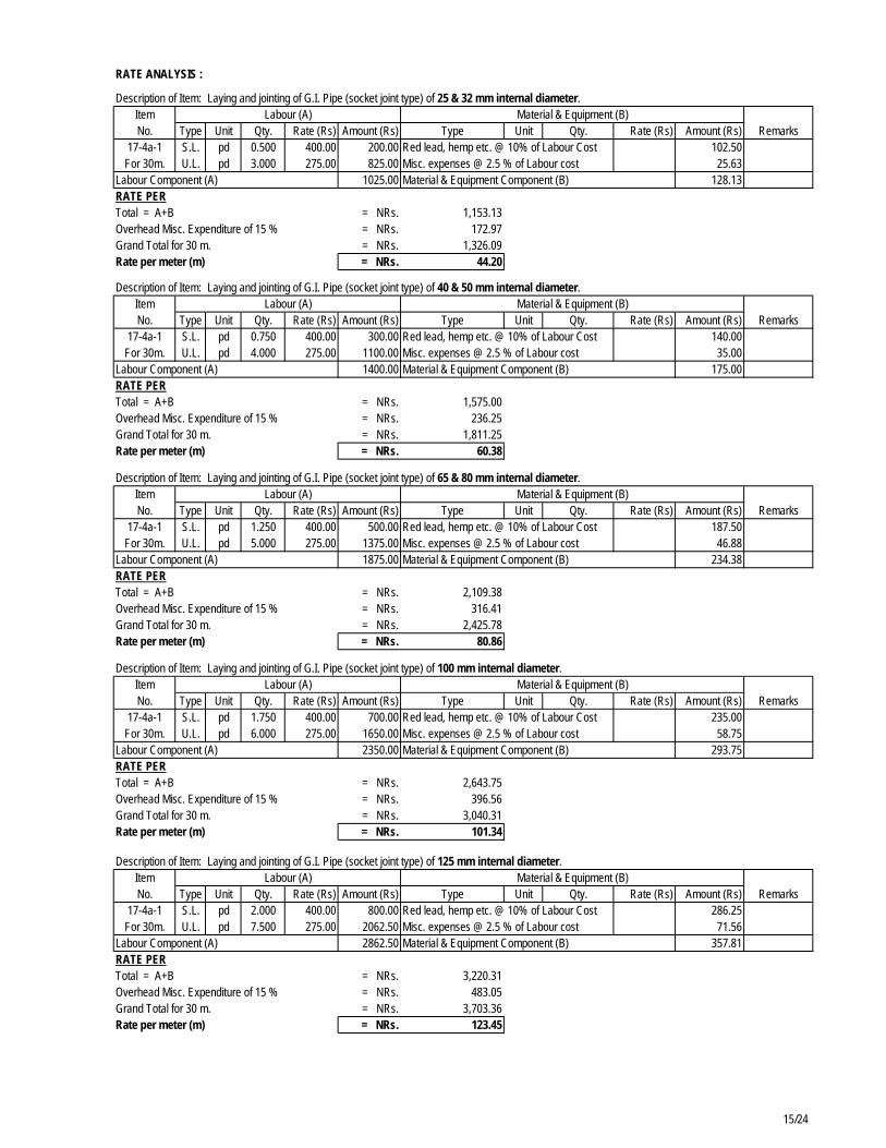
47 The quality of locally available GI pipes is usually not of adequate standard; therefore use of GI pipes should be avoided. In order to use non metallic pipe for diameter less than 150mm in distribution network of the Pilot area, cost of two commonly used pipes was compared. As the cost of trench excavation and backfilling for laying of both type of pipes would be the same, only the cost of pipe (material), laying and joining of pipe and fittings cost have been compared. The cost involved in each type of pipe with respect to laying cost and fitting cost have been estimated, in addition to the pipe cost. Material cost and laying cost of pipes has been estimated as per the Government norms with the help of approved district rate of current fiscal year. Fittings cost per unit pipe length have been assumed as 25% and 10% of pipe material cost for both uPVC and HDPE pipes. This assumption has been made based on past experience and prevailing practices. The total cost for per meter length of pipe of different diameters is compared and shown in table below.
Table 3-6: Comparative Cost Assessment of uPVC and HDPE Pipes
Pipe Dia. Cost of uPVC Cost of HDPE
(mm) Pipe Laying Fitting/m Total Pipe Laying Fitting/m Total
TA 4893 –NEP: Kathmandu Valley Water Supply & Wastewater System Improvement DNI Detail Design Report
Page 14
48 It has been observed that, the unit cost of HDPE is 13% to 23% higher than uPVC pipe. For the present DNI works in the Kathmandu valley it is recommended that all pipes of sizes DN 150 and above shall be DI. For smaller diameter pipes including that for house connections non-metallic pipes, i.e. uPVC, is recommended.
3.4.10 Pressure and Velocity
49 After general assessment of various engineering practices in Nepal and elsewhere in the region, it has been concluded that a maximum velocity of 3m/s would be allowed in the major pipelines, while the minimum velocity should generally not be less than 0.5m/s, especially where tube well water is being transferred which might contain sediment.
3.5 Engineering Design and Approach
50 The primary guiding principle adopted in the engineering design of the Pilot Area has been to improve the existing water supply situation in the area in conformity with the KUKL Service License target in a pre-Melamchi scenario with optimum sizing of the improved pipe network to satisfy the 2025 post-Melamchi scenario. This required striking the right balance between alleviating the problem now and readying the system for later stages with greater availability of water.
51 The existing water supply network also needed to be assessed in terms of its utilization and utility in view of the changed approach being promoted for laying of water distribution mains and installing house connections. In order to work within this guiding framework, extensive survey of the area was done and consultation at the operational level with KUKL and consumers at the household level.
52 Detailed assessment of the existing supply area in terms of constraints and physical limitations for the implementation of the proposed works has also been done. Effective measures are required to ease construction and also facilitate the day-to-day activities of the local residents. Inconvenience to the local residents and businesses needs to be minimized and alternative measures adopted to maintain traffic flow and continuity of utility services in the area. All these factors have been taken into account, while approaching the design to make it not only sound in technical terms but acceptable to the consumers generally.
4. Survey and Investigations
53 All Topographical surveys performed have utilized geo-referenced Total Station methods to provide digitized plans that can be used in CAD and GIS applications. Surveyed maps / plans have an accuracy of +/- 10mm and include all main physical features such as roads, streets, trees, built up areas, etc. with a 100m geo-referenced grid, North point and bar scales. All wards, main roads, important buildings (i.e. schools, temples, etc.) and water courses have name labels (where available) on separate layers with appropriate text sizing to allow prints to be prepared at various scales between 1:200 and 1:5,000, subject to detail requirement.
54 All levels are related to datum levels above Mean-Sea Level as provided by the Survey Department, Government of Nepal with an accuracy of +/- 5mm and are provided on separate digitised layers. Geo-referenced survey monuments and bench marks are provided along the pipeline routes and in the survey areas using existing permanent features or concrete pillars set in concrete. These reference points are shown on the survey plans and in tabular form for reference during construction.
4.1 Engineering Survey
55 Detail designs and civil contracts have been prepared for improving the water supply service in the proposed Pilot area for which it was necessary to up-date existing digital survey maps. The plan survey of the pilot area (approx. 100 Hectares) includes accurate
TA 4893 –NEP: Kathmandu Valley Water Supply & Wastewater System Improvement DNI Detail Design Report
Page 15
plotting of the pilot area boundary, property line to the both sides of existing roads / lanes and other prominent features. The survey plans have been reproduced at suitable scales.
56 The survey has captured all storm water drains or any other visible utility lines (e.g. electricity power cables, sewer / drainage manholes, water valves, etc.) along the roads / lanes which are marked on the drawing. Details of river / drainage channels with respect to the bed level, width and depth have also been provided. Spot levels have been provided at 20m intervals on the centre lines of the road / lane and at every junction.
57 All roads / lanes in the survey area have been provided a reference code. Length with average and minimum width of all roads / lanes has been measured. Type of surfacing and condition of all roads / lanes has also been recorded. Type and number of houses / residential dwellings or other properties in each road / lane have been recorded.
4.2 Survey Map Preparation
58 The main aim of the projection systems adopted for the study was to present map data using ACAD and GIS so that required information could be easily accessed. The selection of a projection system is based on the area (shape, size and orientation) to be mapped and the accuracy requirement for the intended purpose of the maps. The available maps from department of Survey (1:25,000), and other map such as prepared by Valley Mapping project (1:2000) of Kathmandu Valley were in Modified Universal Transverse Projection (MUTM) system. In order to maintain consistency with the national practices, MUTM projection system has been adopted for this Pilot area scheme.
4.3 Base Map
59 An initial preliminary planning exercise was carried out with the help of the Valley map of 1:2000 scale prepared by DHUD under Kathmandu Urban Development Project during 1999 AD. But. because the map was rather dated, additional information had to be added from ‘Google’ earth image of the Pilot area.
60 Based on the preliminary base map, field work for survey was planned. A traverse survey was carried out with the help of Total Station enclosing the Pilot area. Important details such as road widths, monuments, new lanes or roads have been added to the base map for the pipe network planning.
4.4 Existing Pipeline Network Verification
61 Verification of existing pipe has been carried out with the help of map prepared by JICA under "Development Study on Improvement of Water Supply Facilities in Urban Centers and Kathmandu Valley" project. As these maps were prepared during 2005 AD, additional information on existing pipe network has been gathered with the help of technicians from the KUKL Mahankal Chaur Branch office.
4.5 Water Quality Survey
62 It is essential that the quality of water supplied to consumers be of approved standards. The KUKL service license although mentions adhering to water quality standards. Therefore, the recently promulgated National Drinking Water Quality Standards (2062) have been adopted, as prescribed in the Urban Water Supply and Sanitation Policy of 2009. This might require improved treatment of the source water. Some of the major water quality parameters to be monitored and water quality level established is listed in Table 4-1.
63 Other heavy metals and carcinogenic chemicals should not be present in the water for drinking and bacteriological contamination should be nil.
TA 4893 –NEP: Kathmandu Valley Water Supply & Wastewater System Improvement DNI Detail Design Report
Page 16
Table 4-1: Major Water Quality Parameters as per NDWSQS 2062
S.N. Parameter Unit NDWSQS 2062
1. Colour True Color Units (TCU) 5
2. Turbidity NTU 5
3. pH pH Scale 6.5-8.5
4. Taste / Odour Acceptability -
5. Chlorine mg/L
6. Conductivity Us/cm 1500
7. Total Alkalinity as CaCo3 mg/L -
8. Total Hardness as CaCo3 mg/L 500
9. Chloride mg/L 250
10. Flouride mg/L 0.5 – 1.5
11. Sulphate mg/L 250
12. TKN mg/L -
13. NH3 mg/L 1.5
14. Aluminum mg/L -
15. Copper mg/L -
16. Iron mg/L 0.3
17. Zinc mg/L -
18. Arsenic mg/L 0.05
22. Cyanide mg/L 0.07
23. Lead mg/L
24. Manganese mg/L 0.2
27. Nitrate mg/L 50
34. Escherichia coli Cfu/100 ml 0
5. Proposed Distribution Network Improvement
5.1 Distribution Network Configuration
64 Initially, two options were developed for an exercise in optimum option analysis. In the first option, the pipe network was designed with only one tapping point from the existing 600mm diameter pipe at Chabahil Chowk, on the Ring Road. In the second option, two tapping points were considered. These tapping points are at Chabahil Chowk (for the first option) and Mitrapark Chowk. The two tapping points are about 450m apart.
65 Tentative estimates of both distribution system configuration along with residual pressure distribution and its implementation strategies were discussed with senior managers of KUKL on 18th February 2010. As the cost involved for implementation was not considerably different, considering the water management and implementation aspect Option 2 with two tapping points was selected for detail study.
5.2 Basic DNI Concepts and Approach
66 The existing distribution network is in need of immediate rehabilitation. The biggest problem is the aging pipes. The other important issues are of multiple and illegal service connections and corroded GI ½” private lines. The majority of distribution pipes of GI 50mm diameter or less are under sized for present and future demands and have large head losses resulting in very poor residual pressures and in-equitable service. The. GI pipe lines in the system should be systematically replaced.
TA 4893 –NEP: Kathmandu Valley Water Supply & Wastewater System Improvement DNI Detail Design Report
Page 17
67 Few of the existing distribution mains have been designed for present or future population and water demands. In addition, most existing pipes are dilapidated and not strong enough to meet the WUO license pressure service levels. As a result, most existing distribution pipes will be found to be either undersized to meet future water demands or of poor condition and will require replacement with new pipelines based on adopted design criteria.
68 Many existing consumer connections are directly made to large diameter transmission and trunk pipelines. These connections are often made by knocking holes in the pipe which damages the cement lining of DI pipes, causing rusting and weakening of the pipes, resulting is severe leaking. On some major trunk pipelines there are so many consumer connections that over 50% of the water to be delivered is lost. It is recommended, as part of the service management strategy that consumer connections should only be taken from the service area distribution network within supply zones. All consumer connections to main trunk serving different supply zones or service networks shall be removed.
69 One of the principles of providing water supply zones is to be able to monitor the supply service with the use of bulk meters so that problems in the delivery can be identified and rectified. Usually degradation in a service is progressive and action to remedy the problem can be planned in advance. Sometimes failures are sudden and sections of the distribution network need to be isolated in order to carry out repairs. In both cases, disruption in service should be as little as possible and with a minimum number of customers affected.
70 It has been the normal practice for every household or property to make a separate consumer connection to the main distribution pipeline, no matter how far the distance. As a result, side streets and alleys have clusters of ½” GI service pipes. Because nearly every ferrule connection to the distribution main leaks and because the pressure drop in the small diameter service pipes is great, the service pressure and consequent water supply to most properties is very poor. The problem of high pressure drops is exacerbated by the present intermittent supply regime and consequential high peaking factors due to the constrained water supply. This has to be remedied and provisions have been made for replacing leaking pipes and house connections with new pipes and improved connections
71 Rehabilitation of the existing system will not be an easy task. The major problems for implementation are narrow roads, old buildings (in the core areas), congested traffic and complicated network of communication, power and drainage lines. Coordination between all the concerned line agencies during the rehabilitation and improvement work is essential.
5.3 Demand Projection and Allocation
72 As mentioned earlier, the entire Pilot DNI area has been divided into smaller blocks with different urban growth characteristics based on the potential for growth. The pipe network layout was overlaid on the base map of the area and nodes identified. Each of the design nodes was then given a “demand area” for which the individual node has been earmarked to provide / supply water. The population to be served by each node was estimated using the population densities and the area to be serviced by the individual nodes. The base year population at each node was projected using relevant growth rates to establish the design year population. The demand allocation at each node was then established using the nodal population and the per capita demand figures. The average demand flows at each node was then adjusted using the hourly peak factor, which resulted in design flows to be used for the network analysis.
5.4 Network Modeling and Design
73 Hydraulic network modelling and design has been performed using US EPAnet 2.1. Once the initial pipe network for pilot area was prepared, the entire network was modelled using the node and link facilities of EPAnet. All nodes and links were numbered and coded and the parameters required for modelling the network, i.e. length, elevation, base demand
TA 4893 –NEP: Kathmandu Valley Water Supply & Wastewater System Improvement DNI Detail Design Report
Page 18
and discrete pipe sizes of defined materials, were inserted in the model to calculate residual head, velocity of flow, etc. (Refer Figure 5-1: Designed Pressure Diagram). Various runs in a steady state scenario were made. The results of these runs with the optimized results are given in Appendix 2.
Figure 5-1: Designed Pressure Diagram
TA 4893 –NEP: Kathmandu Valley Water Supply & Wastewater System Improvement DNI Detail Design Report
Page 19
5.4.1 Subproject Components
Distribution Mains/Lines
74 The existing distribution mains and lines of the pilot area are supplied from two 600mm diameter pipelines; one running through Siphal and another one through the Ring Road in the east. There is one more distribution main of 500 mm diameter also running along the Ring Road alongside the 600mm diameter pipeline until it diverts to the west from Battisputali Chowk. The first 600mm diameter pipeline is serving as a distribution main to distribute water to downstream areas of Kamal Pokhari, Naxal, Gyaneswor, etc, while the second line is mainly to provide water to New Road and Lagan areas. The 500mm diameter distribution main is for the distribution of water to Baneshwor areas.
75 In the pilot distribution network improvement these distribution mains shall be retained. But, all private connections shall be removed from the distribution main along the Chabahil-Siphal Road and shall instead be connected the new distribution mains.
76 All the existing pipelines equivalent to or less than 80 mm diameter are comprised of GI pipes, which have life of maximum 20 years. In addition, maximum rusting of pipes take place at the location of ferrules further deteriorating the water distribution system. uPVC shall be used to replace all the GI and other pipes of diameter 140 mm or less.
77 Only two types of pipes shall be used in the distribution network improvement works; Ductile Iron (DI) and uPVC. All the pipes of 150mm diameter and above shall be of DI pipes and all the pipes of 140mm diameter or less shall be of uPVC pipes.
78 The total length of DI and HDPE pipes shall be as follows:
DI Pipes 350 mm diameter 120 m 300 mm diameter 70 m 250 mm diameter 167 m 200 mm diameter 1147 m 150 mm diameter 696 m Total 2200 m uPVC Pipes 140 mm diameter 1518 m 125 mm diameter 3775 m 110 mm diameter 3509 m 90 mm diameter 9515 m 75 mm diameter 12262 m Total 30579 m
Chambers
79 All chambers are M-20 Grade RCC Chamber. All the chambers have been designed as per the India standard Code for heavy traffic load (heaviest axle load of 8 ton) and limiting cracking width philosophy assuming other design parameter such as depth of pipe, location of ground water table, soil characteristic, etc. Designs have been made only for estimate and tendering purposes. It is recommended designs of these chambers should be checked and revised, if necessary, to suit particular local conditions and loads during implementation.
Bulk Meters and other Valve Chambers
80 Supply of water to the DNI pilot area will be from the existing 600mm diameter transmission main along Ring Road, at two locations. In order to enhance water auditing two Bulk meter chambers at these locations has been provided. These chambers comprise of control valves (Sluice Valve) and other necessary appurtenances to control water from the transmission main and isolating distribution blocks from maintenance purposes. Similarly,
TA 4893 –NEP: Kathmandu Valley Water Supply & Wastewater System Improvement DNI Detail Design Report
Page 20
other valve chambers have been provided to isolate parts of the distribution system for maintenance or in case of damage.
Pipe Valve Chambers
81 Wherever, there is lack of space and control valves are of smaller diameter, pipe valve chambers have been considered for ease in implementation and use.
Washout Chambers
82 Four Washout Chambers have been provided in the Pilot area distribution network. These washout chambers have been provided along the Dhobi Khola with respect to reduced level of the area and ease in draining.
Air Valve Chamber
83 Air valve chambers with drain pipe and sluice valve has been provided along with outlet structure of brick masonry on the bank of the Dhobi Khola. The air valves are single orifice with throttle of 50ND. Altogether, about 10 air valve chambers are envisaged. The locations of these chambers are tentative based on elevations, depth of pipe and ground condition. Exact location and numbers may have to be revised during implementation.
Water Revenue Meter
84 Dry dial volumetric rotary piston type water revenue meter for all house connections are proposed. These household water meters have 15mm ND and have been recommended for use in KUKL DNI Demonstration Area of Baneshwor.
House Connection
85 All house connections shall be of non metallic pipe in order to reduce leakage at the service connection points. Initially four different options as per the pipe material have been developed. The use of GI, Composite, HDPE and uPVC pipes have been adopted in option 1, 2, 3 and 4, respectively. The implication costs have been assessed. Because the entire length of roads and lanes would be provided with distribution pipes, a service pipe length of 9m has been adopted for the house connection in the estimate. Table 5-1 illustrates cost involved in different option.
Table 5-1: Comparative Cost of House Connections with Various Pipe Materials
Description of Items
Quantity GI Composite HDPE uPVC
U. Cost Amount U. Cost Amount U. Cost Amount U. Cost Amount
86 The KUKL Mahankalchaur Branch office estimated that there are about 4,300 private connections in the Pilot DNI Area, which are expected to increase to about 4,800 by 2012. Accordingly, 4,800 house connections have been proposed in the project costs. Nominal 15mm diameter pipe have been taken for house connection in case of GI pipe Option. In case of others, pipe of 20mm outer diameter (OD) has been considered. The cost of fittings has been lumped to one item as per required number and type of fittings.
TA 4893 –NEP: Kathmandu Valley Water Supply & Wastewater System Improvement DNI Detail Design Report
Page 21
6. Project Cost Estimation
6.1 Capital Cost of Water Supply System
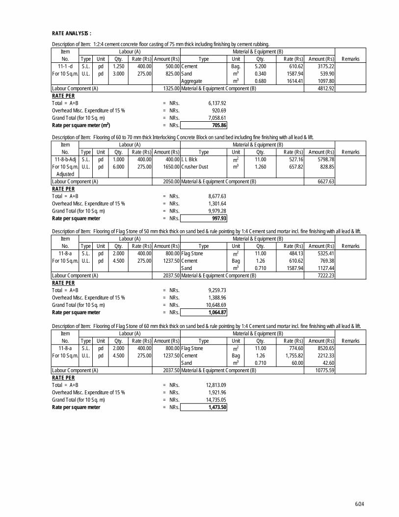
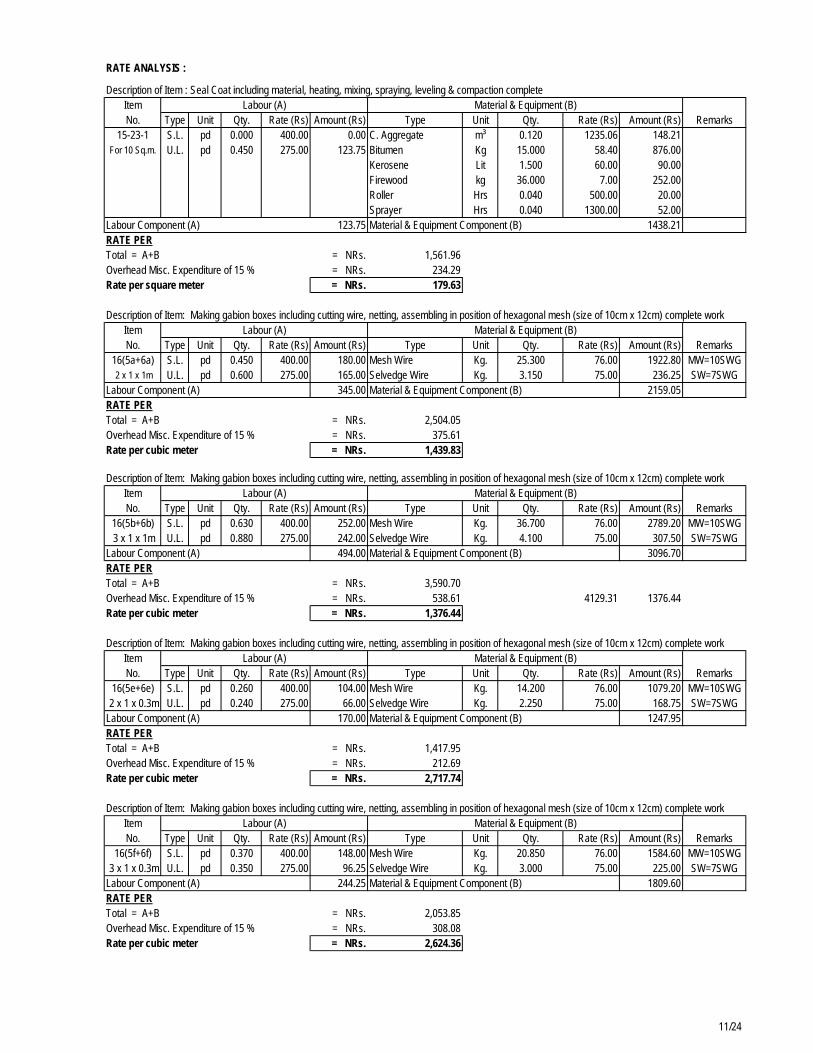
6.1.1 Unit Rate Analysis
87 Unit rate of most of the work items for the Pilot Area DNI works has been established by utilizing Construction Norms of GON (Second Revised Edition, 1993). Reasonable interpolation or extrapolations in inputs of material and labour have been done for few items, which are not mentioned in the GON Norms. This has been done based on past experience and inputs used by recently implemented projects of similar nature.
88 Rates of construction materials, transportation and that of skilled and unskilled manpower have been taken from approved district rates of Kathmandu District for the current fiscal year (2009/2010 AD). The market price of commonly used items (other than DI Pipe, DI Fittings and it appurtenances) are used from the approved district rate.
89 However, market price of items such as Ductile Iron Pipes, Ductile Iron Fittings, Revenue Water Meter, bigger diameter Valves, etc (selective items) are neither available in local market of Nepal nor mentioned in approved district rates. Most of such rates have to be obtained from manufactures from different countries. As there are various types of items, the market prices are not available from a single manufacturer or agent. Therefore, in order to establish market prices of those items within relatively short period of time, old unit prices have been used and adjusted for current prices. The unit prices of most of the item have been adopted from different reports prepared under various project/Programme under GoN.
90 As the reports were prepared in different years by different consultants, the approach, method and assumption of determining unit price of item were found different. Some of the old reports did even not mention about the market and source of unit price. Some reports had taken different countries of origin in order to determine unit price for pipe and its related fittings.
91 In order to establish unit price for Pilot DNI Area, the entire unit price of items adopted in previous studies and unit prices provided by different manufactures have been incorporated. The unit price of particular year has been adjusted to the current year unit price with the help of consumer price index of Kathmandu valley (CPI). The overall price index published by Nepal Rastra Bank has been taken and these indices are also triangulated with overall CPI of neighbouring countries namely; India and China. The overall price index published by Nepal Rastra Bank has been adopted for this purpose. As the Nepalese CPI of current year is not available, CPI of ten percentage has been assumed based on data from past years on published CPI.
92 The product of CPI of different years have been used to establish multiplication factor for the adjustment period (number of year from the study/implemented period to current year). Once the multiplication factors have been established, the unit prices of all items of different studies of different year have been brought into current unit price (adjusted price). The available unit prices of different manufactures are also used for selective items
93 The unit prices have further refined and made realistic by using available unit prices of bid prices of different contracts under Loan 1820 NEP. Details of the unit rate analysis are provided in Appendix 5.
6.1.2 Quantity and Cost Estimations
94 Quantities of all construction works including general items have been performed using standard engineering practices. Details of quantity estimates for various structures, pipelines, excavations, etc. are provided in Appendix 4. Based on the unit rates derived in the rate analysis and the unit quantity, unit cost estimates has been prepared. The total cost estimate of DNI Pilot area scheme has been estimated based on unit cost estimates. The
TA 4893 –NEP: Kathmandu Valley Water Supply & Wastewater System Improvement DNI Detail Design Report
Page 22
abstract of the cost has been prepared by identifying the quantity of work and unit rate analysis. The relevant details of cost estimates are given in the Appendix 3.
95 An additional 10% of the cost is provided for physical contingencies plus 13% VAT in order to estimate final cost of the scheme. The cost for the scheme has been estimated as NRs. 183,976,468.00, which is summarized in the Table 6-1.
Table 6-1: Pilot DNI Area – Cost Estimate
S. Description of Items Qty Unit
Rate or Avg. Rate
Total Cost (NRs.) No.
A Preliminary Items 1 Job 3,692,585.00 3,692,585.00
B Provisional Item 1 Job 6,973,064.00 6,973,064.00
C Civil Works
1 Pipeline Trench Excavation & Backfilling 1 Set 10,268,388.88 10,268,388.88
2 Pipe Cost 1 Set 22,563,795.64 22,563,795.64
3 Fittings 1 Set 9,952,215.36 9,952,215.36
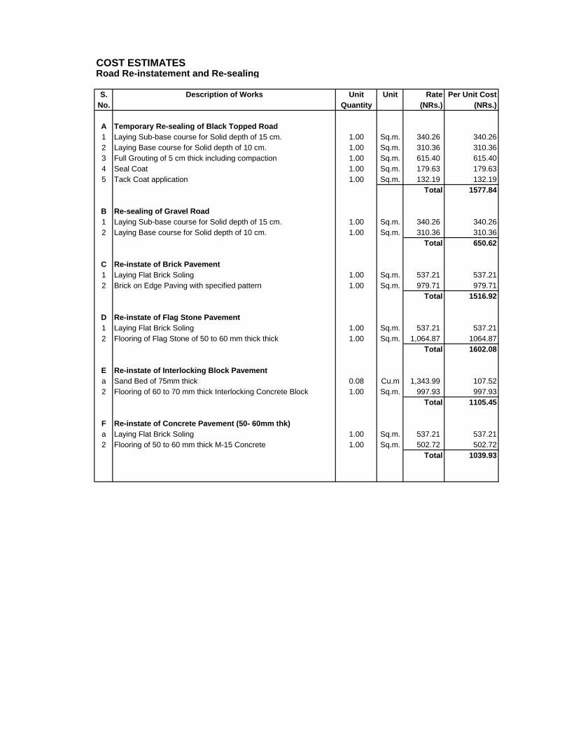
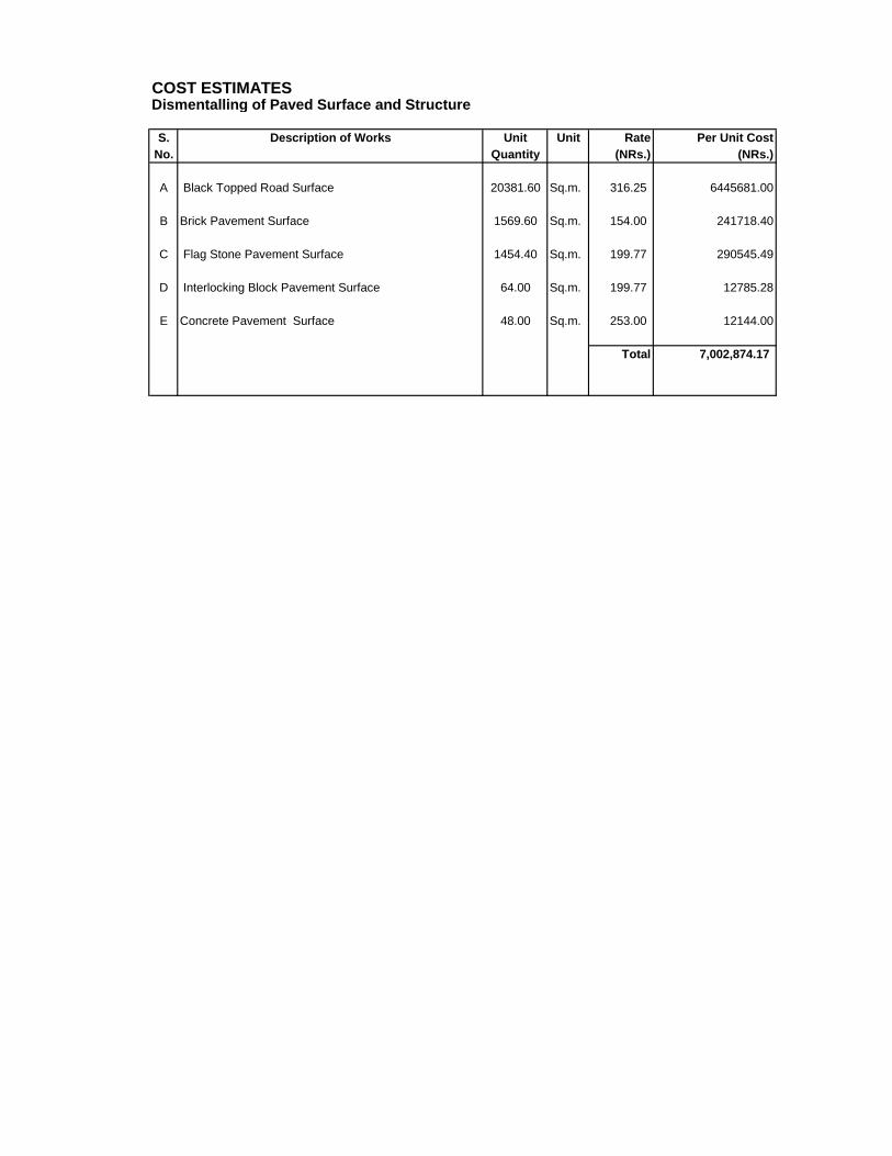
4 Dismantling Works 1 Job 7,002,874.17 7,002,874.17
5 Main Tapping Chambers (at Two Chowks 1.5 mx 2.5m)
7 Valve and Washout Chambers (1.5mx1.5m) 14 No. 147,652.93 2,067,140.98
8 Valve and Washout Chambers (1.0mx2.0m) 8 No. 181,240.15 1,449,921.17
9 Air Chambers (1.0mx1.0m) 10 No. 108,020.45 1,080,204.46
10 Pipe Valve Box 8 No. 3,397.88 27,183.04
11 Fire Hydrant 10 Nos. 25,000.00 250,000.00
12 Temporary Re-sealing of the Black topped Road
20,381.6 Sq.m 1,577.84 32,158,903.74
13 Re-instate of the Gravel Road
2,705.6 Sq.m 650.62 1,760,317.47
14 Re-instate of the Brick Pavement
1,569.6 Sq.m 1,516.92 2,380,957.63
15 Re-instate of the Flag Stone Pavement
1,454.4 Sq.m 1,602.08 2,330,065.15
16 Re-instate of the Interlocking Block Pavement 64 Sq.m 1,105.45 70,748.80
17 Re-instate of the Concrete Pavement 48 Sq.m 1,039.93 49,916.64
18 Thrust Block 45 Cu.m 8,609.87 387,444.15
19 House Connections 4800 No 7,729.61 37,102,136.16
20 Miscelleneous Work 1 Job 8,379,430.00 8,379,430.00
Sub-Total (A+B+C)
152,173,367.33
D Contingencies for workchart staff and small miscelleneous expenses 5% 7,608,668.37
E Sub total including workchart staff and small miscelleneous expenses
159,782,035.70
F Contingencies for price adjustment 10% 15,978,203.57
G Physical contingencies 10% 15,978,203.57
H Sub-total including contingencies
191,738,442.84
I Value Added Taxes (VAT) 13% 24,925,997.57
J Total Estimated Amount (NRS)
216,664,440.41
6.1.3 O & M Cost of Water Supply System
96 As the pilot area is under the operational management of Mahankal Chaur Branch Office of KUKL, its operation and maintenance shall also be carried out by the same office. Regardless of the improvement in the pilot area, the existing distribution structure concerning other parts under the jurisdiction of Mahankal Chaur will remain same as of now. Hence, there will not be any significant change in the operation and maintenance parts.
TA 4893 –NEP: Kathmandu Valley Water Supply & Wastewater System Improvement DNI Detail Design Report
Page 23
Nevertheless, the operation of the distribution system inside the pilot area will be comparatively much easier. Also, it will not require any maintenance of the system for the first three years after the completion of the pilot project.
7. Socio-economic Characteristics of Pilot Area
7.1 Location and Accessibility
97 The proposed DNI pilot area is located in ward No.7 and 8 of Kathmandu Metropolitan City. The present population of the area is estimated at about 20,000 with 4,000 households. It comprises of about 100 hectares. The major settlements are Sifal, Chabel, Gagahiti, Bulbule, Jayabageshowri, Mitrapark, Kalopul, Binayak Tole, Katubahal and Panika Tole.
98 A socio-economic survey was conducted in the Pilot DNI Area to establish baseline scenario on the existing services, socio-economic characteristics and demand for improved supply in the area. A total of 219 households were randomly selected for the survey from the list of households with metered and unmetered connections as provided by the KUKL’s Mahankal Chaur Branch Office.
7.2 Households and Demography
99 The average family size in the DNI area is about 5.6. It is slightly higher than the national average (refer Table 7-1). The average family size in the Kathmandu Metropolitan City is 4.4 whereas the national average is 5.45.
Table 7-1: Demographic Features of the Sampled Households
Study area
No. of Households
Population HH size
Population by Age Groups (in %) Male Female Total NA 0-15 16-45 46-65 65 &
over Total
DNI pilot area
219 609 615 1,224 5.6 0.2 17.7 55.1 18.2 8.8 100
Source: Field Survey, November 2009
100 The above table shows that the biggest representation in the population is of age group between 16 to 45 (55.1%) followed by another age group between 46 to 65 (18.2%). The percentage share of the children below 15 years is about 18%.
101 Out of 219 households interviewed for the survey, 36.1% were female headed households. Of the total female headed households, about 20.3% were widowed.
7.3 Ethnicity
102 Table 7-2 indicates the different ethnic groups residing in the DNI pilot area. Brahmin (41%), Newar (34%) and Chettri (11%) are the major ethnic groups. Other prominent ethnic groups are Gurungs (5%), Rais (3%) and Lamas (3%).
Table 7-2: Ethnic composition of the households
Ethnicity No. Percentage (%)
Brahmin 90 41.10
Newar 75 34.25
Chettri 24 10.96
Gurung 11 5.02
Rai 6 2.74
Lama 3 1.37
Others 10 4.56
TA 4893 –NEP: Kathmandu Valley Water Supply & Wastewater System Improvement DNI Detail Design Report
Page 24
Total 219 100.00
Source: Field Survey, November 2009.
7.4 Education
103 Table 7-3 indicates the literacy rate which is one of the significant indicators of economic and social development status. Out of 219 households which were interviewed, about 93% family members are literate.
Table 7-3: Education Status of the households
DN
I P
ilot
are
a
Illite
rate
Lite
rate
but
no s
cho
olin
g
Gra
de I
-V
Gra
de V
I- X
10+
2
com
ple
te
Gra
dua
te &
a
bo
ve
Infa
nt
Not
att
en
din
g
sch
oo
l un
til
sch
oo
l tim
e
Kin
derg
art
en
Male 15 27 61 142 91 246 12 3 11
Female 71 68 62 154 111 127 11 1 6
Total 86 95 123 296 202 373 23 4 17
Source: Field Survey, November 2009.
7.5 Occupation and Economic Activities
104 The sampled household survey reveals that most of the household members are engaged in services (18.4%) followed by trade and business (9.9%). About 32% of the economically active population are students. Other major activities are labour within and outside the country. Similarly, 17% family members are engaged in household work. Details of the economic activities of the sampled household members are given in the Table 7-4.
Table 7-4: Economic Activities of the Household Members (%)
DNI Pilot area
Service (Public)
Service (Private)
Trade & business
Labour Labour abroad
Student Dependent (children)
Household work
None
Male 48 (3.9) 104 (8.5) 77 (6.3) 17 (1.4)
24 (2) 208 (17) 15 (1.2) 2 (0.2)
113 (9.2)
Female 20 (1.6) 51 (4.2) 44 (3.6) 4 (0.3)
11 (0.9)
182 (14.9)
10 (0.8) 207 (17) 84 (13.6
) Total 68 (5.6) 156
(12.8) 121 (9.9) 21
(1.7) 35
(2.9) 390
(31.9) 25
(2.1) 209 (17) 197
(16) Source: Field Survey, November 2009.
7.1.6 Economic Profile
105 The field survey findings revealed that the majority of the households depend on more than one source of income for their livelihood. House rent is identified as the main source of income (27.9%) followed by trade and business in the surveyed area (21.6%). Other major sources of income of the household are service (18.4%), followed by pension (8.6%) and sale of agriculture and livestock products (4.1%). It has been found that more than 90 % of the household have tenants.
106 Out of the total 1,222 household members, 424 (35%) people are actively engaged in the above income generating activities. Among the total economically engaged population, the number of female is 136 (32%) in comparison with the male 288 (68%).
7.7 Assets Owned by Households
107 The households were also asked about the type of facilities they are possessing. The survey found that almost all the households have television, mobile phone, gas stove, pressure cooker and rice cooker. More than 70 % of the households have micro oven,
TA 4893 –NEP: Kathmandu Valley Water Supply & Wastewater System Improvement DNI Detail Design Report
Page 25
radio/transistor and electric fans. More than 60 % possess computer, VCD/DVD/VCR, refrigerator. Nearly 10 % of the households have the washing machine and motor vehicles. Table 7-5 shows the household assets of the project area:
Table 7-5: Facilities possessed by the Sampled Households
S.N. Facilities Total households No. of HHs possess Percentage
1 Radio/Transistor 219 171 78.08
2 Television 219 214 97.72
3 Computer 219 149 68.04
4 VCD/VCR/DVD 219 136 62.10
5 Bicycle 219 64 29.22
6 Motorcycle 219 115 52.51
7 Car/jeep 219 30 13.70
8 Refrigerator 219 148 67.58
9 Mobile Phone 219 212 96.80
10 Kerosene stove 219 145 66.21
11 Electric stove 219 42 19.18
12 Gas stove 219 216 98.63
13 Washing machine 219 22 10.05
14 Rice cooker 219 184 84.02
15 Pressure cooker 219 216 98.63
16 Electric fans 219 168 76.71
17 Air conditioner 219 4 1.83
18 Micro wave oven 219 49 78.08
7.8 Type of House and number of rooms
108 About 92% of the sampled families have pakki/ or pillar system house (brick walls, cement floor, RBC/RCC roof), with only 8% having semi-pakki (made of stone/brick with mud mortar). About 38% of the houses have 2 floors, 37% have 3 floors and 13% have more than 3 floors.
109 It has been found that more than 30% of the houses have 7 to 9 rooms while 10% of the households have more than 15 rooms in their buildings. This shows that majority of the house owners have provided their rooms for rent. The study revealed that more than 90% of the sampled households have provided their rooms on rent. The following table shows the average number of rooms in the sampled households.
Table 7-6: Average rooms in the sampled households
Average no. of rooms No. of Households Percentage
Below 4 12 5.5
4-6 55 25.1
7-9 68 31.1
10-12 42 19.2
Percentage13-15 20 9.1
More than 15 22 10.0
Total 219 100.0
Source: Field Survey, November 2009
TA 4893 –NEP: Kathmandu Valley Water Supply & Wastewater System Improvement DNI Detail Design Report
Page 26
7.9 Poverty Status
110 During interviews, the respondents were asked about their income source for their livelihood. It is found that the average annual household income is about NRs. 370, 144 and average per capita annual income is about NRs. 68,545. According to the government’s National Poverty Policy, per capita income of NRs. 10,000 is required to secure a position above poverty level. On the basis of the family size and the minimum income to secure a position above poverty level, the minimum household income has been calculated as NRs. 56,000. Based on this calculation, about 4 households in the DNI area having annual household income of less than 56,000 are identified as poor. Table 7-7 provides the number of households with the range of average monthly income.
Table 7-7: Average monthly income of the households (in NRs)
Income range No. of HHs Percent
Below NRs. 5,000 4 1.83
5001-10,000 9 4.11
10,001- 15,000 22 10.05
15,001-20,000 30 13.70
20,001- 30,000 68 31.05
30,001 -40,000 35 15.97
40,001-50,000 17 7.76
More than 50,000 27 12.33
NA 7 3.20
Total 219 100.00
Source: Field Survey, November 2009
7.10 Household Income and Expenditure
111 It has been reported that the household income of the surveyed area derives mainly from services (govt. & private), house rent and trade & business which constitute about 29%, 28% and 22% respectively of the total income. The income from remittances, labour/wages, local farm/livestock income-generating opportunities are limited. Pension is also one of the main sources of income of the households which constitute about 9% of the total source of income of the surveyed households. The main features of the reported sources of income and expenditure recorded in the survey (Tables 7-8 and 7-9) are as follows:1
The annual average per capita income of the surveyed DNI area range from a minimum of NRs. 38,571 to a maximum of NRs. 162,000 where as the yearly
average per capita expenditure range from NRs. 32,760 to NRs. 92,000.
As mentioned above that the major source of income is government and private services (28.9%), house rent (27.9%), trade & business (21.6%). The other
source of income mostly listed were pension, remittances and income from labour
(e.g. skilled & unskilled labour) within the country and outside the country.
With regards to expenditure, it was most frequently reported for food including daily consumption items (47.9%) followed by education and health (28.9%).
1 It should be noted that the measurement of income and expenditure by means of questionnaire surveys is limited. Questions on income may be seen as an invasion of household privacy, and the data collected is entirely dependent on respondent recall and integrity.
TA 4893 –NEP: Kathmandu Valley Water Supply & Wastewater System Improvement DNI Detail Design Report
Page 27
Table 7-8: Reported Sources of Income of the Households
S.N. Income Source % of total annual income
1 Agricultural /Livestock 4.05
2 House rent 27.86
3 Trade/ business 21.59
4 Self employed/ industries 0.35
5 Labour/Wages 2.23
6 Services (government/private) 28.91
7 Pension 8.57
8 Remittances (Labour abroad) 2.62
9 Others 3.83
Total 100
Table 7-9: Reported Expenditure by Type of the Households
S.N. Expenditure Item % of total annual expenditure
1 Food & daily consuming items 47.9
2 Education /health 28.9
3 Electricity bill 6.2
4 Water tariff 1.5
5 Others 15.5
Total 100
7.11 Willingness to Pay
112 It was found that about 50% of the households were not willing to pay more than NRs.200 as minimum charges for 10,000 liters. About 18 % of the households were willing to pay more than NRs.500 for hygienic and regular supply of 10,000 liters per month. The Table 7-10 shows the number of household and their willingness-to-pay different amounts for improved water supply from KUKL.
Table 7-10: Willingness to Pay for Hygienic and Regular Supply of Water
Willingness to pay for the minimum charge of 10,000 litres
Less than
Rs. 200
Up to Rs. 250
Up to Rs. 350
Up to Rs. 450
More than
Rs. 500
Don’t Know
NA
No. of Households 100 24 13 18 36 5 23 Source: Field Survey, November 2009
7.12 Access to Safe Drinking Water and Sanitation
113 Water is being supplied to different communities in the area by KUKL through piped network from the Mahankal Chaur reservoir. But the quantity of water supplied by KUKL is not sufficient to meet the household demand. Hence, most of the households have another source of water within their premises like dug well and hand pump etc. It has been reported that almost all the households have toilet facilities. But some households (15 %) still lack the sewerage and sanitation facilities. Some households reported that they are suffering from the water borne disease like typhoid, skin disease, fever, hepatitis due to the supply of unsafe drinking water by KUKL. The following table provides the status of drinking water supply and sanitation facilities.
TA 4893 –NEP: Kathmandu Valley Water Supply & Wastewater System Improvement DNI Detail Design Report
Page 28
Table 7-11: Access to drinking Water and Sanitation
Access Yes No Don’t know No response Total
Piped drinking water supply
217 2 0 0 219
Hand pump/tube well/well/ boring (other source)
69 96 0 54 219
Toilet 218 0 0 1 219
Sewerage & sanitation 205 12 1 1 219
Source: Field Survey, November 2009
7.13 Water Consumption
114 It has been found that the total consumption of water excluding tenants is about 480 liters per day in wet season while it decreased to 380 liters per day in the dry season. The per capita consumption is 86 liter in wet season and 68 liters in dry season.
7.14 Direct Pumping of Water from Mains
115 Nearly 50% of the sampled households use electric pump to forcibly draw water from the KUKL pipelines. They argue that they cannot get adequate water and need to use an electric pump.
7.15 Household’s Opinion on Water Supply
116 The surveyed households were asked about their perception regarding the water supply of KUKl. Out of 219 households interviewed, 53.4% households indicated irregular supply of water. About 51% of the households were not satisfied with the quantity of water supplied. Similarly, 26% complained about the water pressure.
Table 7-12: Household’s opinion on KUKL Water Supply (Multiple answers)
S.N. Opinions No. of respondents Percentage (%)
1 Nothing to say 27 12.3
2 Supply hour 50 22.8
3 Available quantity of water 111 50.7
4 Pressure 56 25.6
5 Regularity 117 53.4
6 Maintenance in the Leakage 44 20.1
7 Schedule 26 11.9
8 Quality 62 28.3
9 Others 44 20.1
10 Equal Distribution 3 1.4
Source: Field Survey, November 2009
117 The study on “Kathmandu Valley Water Distribution, Sewerage and Urban Development” made by Kanako Kishi during 2008, found that about 50 %, 39 % and 44 % households of Kathmandu Valley were satisfied with the quantity available, regularity and water pressure respectively.
7.16 Sewerage and Sanitation
118 When asked about the existence of sewer system in the surveyed area only 12 households reported that there exists some kind of sewerage system. None of them reported the existence of combined sewer systems in the area. About the problem of sewerage, only 35 (16%) households reported the clogging of sewerage pipes from time to time. The household members were also asked about their willingness to pay for improved
TA 4893 –NEP: Kathmandu Valley Water Supply & Wastewater System Improvement DNI Detail Design Report
Page 29
sewerage system in the area. About 46% informed that they want to pay as usual i.e. 50% of the water tariff or less than Rs 200, where as 11.4% reported that they are willing to pay up to Rs.250. About 16% were willing to pay more than Rs.500 for the hygienic and regular supply of 10,000 liters of water. Other households did not want to comment on this question.
119 It was found that different agencies have constructed sewer lines in the study area.
120 It was found that about 57% of the households use water sealed toilet with flush, whereas 42% use water sealed toilet without flush.
121 About 28% of the household still dispose their solid waste into the septic tank and majority of them cleaned the tank within 2 to 5 years of period mostly using private firms.
7.17 Gender Issues
122 According to 2001 census, about 15 5 households have been reported as women headed household. In the urban areas it was a bit more than the country as a whole i.e. 17% in 2001. The current survey in DNI area indicates that about 36.1% of the households were women headed households. Of the total female headed households, about 20.3% were widows.
123 There is still some difference in the literacy between male and female. It has been found that about 88% of the female were literate in comparison to 97% of male population.
124 About 17% of the women are housewives. Only 11% of the female members of a family are found to be involved in income generating activities compared to 22% of the male members. The sectors, in which they are involved, are trade, business and labour related activities in and outside the country. It has been reported that in addition to the involvement in income generating activities, women also carry out households activities like cooking, cleaning, washing clothes, child care, care of elderly members of their family, etc. The following table shows the household activities by gender.
125 Besides, the respondents were also asked about the involvement of women in decision making of the household matters like in finance, education, health care, purchase of assets, day to day households matters etc. It has been found that women are involved in the decision making of almost all household matters. The following table provides the status of women in decision making process.
Table 7-14: Involvement of women in decision making of the household matters (%)
Household matters Yes No NA
Finance 88.6 10 1.4
Education 76.3 16.9 6.8
Health care of children 75.8 16 8.2
TA 4893 –NEP: Kathmandu Valley Water Supply & Wastewater System Improvement DNI Detail Design Report
Page 30
Purchase of assets ( land and buildings) 74 18.7 7.3
Day to day activities 95 1.4 3.6
Decision on social function and marriage 69.4 10.5 20.1
Source: Field Survey, November 2009
126 In most of the developing countries, the family land and household assets have been owned by male population. In some cases both the male and female owned through inheritance land and assets. However, from last few years, the ownership of women on land has increased in Nepal due to the Government policy of 20 % rebate/concession on the land registration fees while purchasing land from other. It is clear from the table below that almost half of the household’s women own assets like land, house and other structures. Majority of them are also allowed to keep money separately in banks or other financial institutions.
Table 7-15: Women ownership of assets
Ownership Yes No NA
Land 48.9 28.3 22.8
House & other structures 50.7 27.4 21.9
Keeping money 65.3 15.5 19.2
Others 1.0 2.7 96.3
Source: Field Survey, November 2009
127 The participation of women in social, political, religious, community gatherings has increased in recent years in Nepal. During the survey in the sampled households, the respondents were also asked about gender participation in community meetings. The percentage of female alone in social/religious gatherings was slightly more than the men, whereas participation of men in community gatherings is much more higher than the female. However, around 50 % of both male and female together participate in the social/religious work. The following table shows the participation status of both male and female in different social activities.
Table 7-16: Participation in the social activities by sex
Social activities Male
Female
Both Male & Female
NA
Social/Religious work 10 12.3 49.3 28.4 Community gatherings/meetings 17.8 6.8 23.7 51.3 Political gatherings/meetings 11 0.9 8.7 79.4 Charity/club 7.3 1.8 8.2 82.7 Others 3.2 0.9 4.1 95.8
Source: Field Survey, November 2009
TA 4893 –NEP: Kathmandu Valley Water Supply & Wastewater System Improvement DNI Detail Design Report
Page 31
8. Environmental Assessment and Considerations
8.1 Baseline Environmental Scenario
128 Kathmandu Valley has gone through a phase of rapid and unplanned urbanization and industrialization without adequate infra-structural development and the Pilot DNI Area is no exception. The Pilot DNI area is also suffering from chronic water shortages and inefficient service delivery. The area is very densely populated and the population has been increasing rapidly. During the last three decades, the growth in population has been significantly driven by in-migration. The in-migration is largely due to better employment and business opportunities, better educational and medical facilities, but also countrywide insurgency and security concerns of recent years.
129 The rapid un-planned urbanization of the Kathmandu Valley including the Pilot DNI Area has brought negative impacts to its overall development. Water has became scarce as demand exceeded supply. Lack of operational wastewater system facilities has converted the adjoining Dhobhi Khola into a highly polluted watercourse. Congested and crowded roads brought hardship to travellers and road junctions became garbage dumping sites. Despite these negative impacts, the urbanization of the area has continued at a similar rate for the past 10 years.
8.2 Environmental Impacts due to Project Construction
8.2.1 Physical Environment
Soil Erosion and Slope Stability due to Excavation
130 Impacts likely to occur from the improvement and construction of the water distribution system will include trench excavations and topsoil stripping which may induce soil erosion, and slope instability. Haphazard disposal of spoil materials may create erosion problems, disturbances to the existing drainage lines, and changes in the existing land use practices. Mitigating measures to be used are: the separate stockpiling of topsoil in a safe yard for further use; spoil disposal at designated and stabilized sites; compaction of the backfill of excavated areas including replacement of topsoil; avoiding work during the rainy season as much as possible; mulching to stabilize exposed areas; use of bioengineering techniques (e.g. re-vegetating areas promptly); providing channels and ditches for post-construction flows; lining of steep channels and slopes (e.g. use of jute matting); preventing off-site sediment transport using settlement ponds, and silt fences.
131 Impacts of surface water discharges to the local drainage from trench excavation can be mitigated by the use of settling tanks before discharging the water to waterways.
132 Excavation and laying of pipelines at river crossings could have adverse impacts on the river water quality and the aquatic ecosystem. Mitigation measures to be used are: construction to be done in the dry season only; use of river diversions with bundings; prior notification to temple officials of construction activities; and driving and foundations at pipe bridge sites to be bunded off from the river.
133 Deep excavations can intercept and interfere with the localized groundwater thereby affecting flows from irrigation canals, and springs and wells causing water shortages. Mitigation measures to be used are: Local wells and springs and irrigation canals to be bunded from temporary spoil dumps; local wells and spring fed spouts or kuwas to be monitored particularly downhill of excavations plus temporary supply provided if flow is affected; permeable base and side backfill required at deep excavated sites or an alternate source of drinking water provided at the existing location.
TA 4893 –NEP: Kathmandu Valley Water Supply & Wastewater System Improvement DNI Detail Design Report
Page 32
Change in River Hydrology and Morphology
134 The construction, rehabilitation and operation of the water distribution networks and sewerage system could have impacts on the river hydrology and morphology due to quarrying from river beds for sand and gravel particularly during the dry season. Water pollution problems could occur because of the dumping of spoil materials into the river, excavation of boulders from the river channel, direct disposal of liquid wastes, and leakage of oil and lubricants. Quarrying/mining activities in river/streams for extraction of construction materials shall not be done so as to change the river cross sections and longitudinal profiles and should be done from approved sources.
Water and Land Pollution
135 Dumping of wastes, discharge of wastewater effluents from toilets into the river can pollute the river water making it unhealthy for downstream users. Mitigation measures to be used are: avoiding construction labour camps facilities within the drainage area; providing designated areas with collection of bins for wastes; providing toilet facilities and prohibiting open defecation; and prohibiting washing of vehicles next to rivers and streams.
136 Pollution of land and water could also be mitigated by the proper storage of construction aggregates, hazardous toxic materials and lubricating oils in safe areas (warehouses), used tyres, exhausted batteries; and the proper segregation and disposal of chemical containers, packaging materials, plastic bags etc. Provide training to the workforce on the safe handling of toxic materials and OHS measures during construction could help in mitigating many of the adverse impacts mentioned above.
Pollution due to Air, Noise and Vibrations
137 Earth excavation, construction materials and stockpiling, aggregate crushing, drilling, quarrying and plying of vehicles will produce dust (TSP, PM10), hydrocarbons (CO, CO2, CH4), SO2, NOX, H2S, etc, noise and vibrations. Plying of trucks on non-metallic roads will produce huge amounts of dust thereby deteriorating the air quality and increase noise levels to above 90 dBA affecting health.
138 Mitigating measures to be employed are: Dust suppression on roads or at open sites by sprinkling water as required at regular intervals; covering earth stockpiles using plastic sheets or cement jute bags; routine monitoring of dust (TSP, PM10), sound and vibrations at regular intervals; limiting vehicle speeds and banning power horns; seeing that vehicles comply with the National Vehicle Mass Emission Standards, 2056 BS; fitting of mufflers in vehicles to control noise; regular maintenance of vehicles; regular maintenance of vehicles; prohibiting the operation of crushing plants and construction vehicles between 7 PM to 6 AM in residential areas; compensating the damages caused by vibrations to buildings and providing proper ventilation in confined working areas.
139 Adverse impacts could be caused due to inadequate buffer zones around pumping and treatment plants to alleviate noise and other possible nuisances, and protect facilities. Adequate alleviation measures (including developing buffer zones around the treatment plants) should be included in the project designs. .
8.2.2 Biological Environment
140 Although most of the construction and improvement works will take place in urban areas, there will be only some impacts on the ecological resources (loss of trees and vegetation, disruption of protected areas, damages to fisheries and riverbed aquatic ecology) that could be impacted due to: vegetation clearance and loss of species due to construction of project structures; fuel wood and non-timber forest products (NTFP) collection by workforce and vegetation clearance for construction activities; and construction activities at pipeline crossings over riverbeds.
TA 4893 –NEP: Kathmandu Valley Water Supply & Wastewater System Improvement DNI Detail Design Report
Page 33
141 Mitigation measures are: Cut only trees that are marked and have been agreed by the Department of Forestry for removal and plant and rear tree saplings at the rate of 25 saplings for each felled tree; prohibit the use of fuel-wood and timber collection; prohibit hunting, the illegal collection and trade of NTFPs; provide LPG/kerosene to the workforce; stockpile the felled trees and take permission from concerned authorities for their use; compensate all private trees and community forests affected. To save the fisheries and riverbed aquatic ecology, work should be done in the dry season only and river diversions and bunding-off of sections carried out.
142 Endangered species and protected areas do not fall within the construction areas and mitigation measures are not required.
8.2.3 Socio-Economic and Cultural Environment
143 As per the approved EIA of 2000 for the Melamchi Water Supply Project, approximately 1,100 workers were estimated to be employed every day for the construction and improvement of the Water Supply Networks. About 60% of the workers required for the project were estimated to be available locally, and at least 30% of the workers should be local. Women should be given preference for employment as far as feasible and practical and ensure that at least 15% of the unskilled workforce shall be women (Norplan, 2002).
Compensation and Rehabilitation as per the Resettlement Plan (RP)
144 Contractor’s temporary land use and housing acquisition and compensation to affected people is one of the most important impacts of any construction project if its progress is not to be hampered. The mitigation measures are: Avoid involuntary displacement; compensation resettlement according to agreed Entitlements Policy and RP; make arrangements for a “grievance redress committee” to look into the grievances; restore temporary sites to their natural or stable conditions as per agreements with the land owners; plant exposed areas of temporary sites with endemic vegetation; make sure that the proponent reports in writing that temporary areas have been vacated and restored to pre-project conditions before acceptance of the works; provide employment opportunities to the affected people; provide all possible assistance to the displaced people until they are settled; provide disturbance and rehabilitation costs; protect the traditional rights of the local people; compensate for any loss of crops, trees and other natural resources and establish a technical committee to assess the compensation for damages caused by vibrations of construction equipment and vehicles.
Reinstatement of Damaged Community Services and Infrastructure
145 Construction activities could have adverse impacts on community services and infrastructure. To mitigate these impacts, compensate or reinstate/relocate community assets that are disturbed such as temples, bridges and irrigation canals, electricity poles, telephone lines, drinking water pipes, sewerage lines, roads, trails, cremation sites etc. to the satisfaction of the people. Establish a technical committee to assess the compensation for damages caused by vibrations (photographs of the damaged structures should be taken and compared to the baseline photographs taken before construction).
Influx of Outside Workforce, Money and Unwanted Activities
146 Alcohol abuse, gambling, prostitution and other social disharmony are likely to arise in the construction site. There will be an influx of workers from outside to the project site with their immediate family members, increasing crime and stress. This will create unwanted congestion and exert pressure on the limited local resources. The mitigation measures to be carried out are: Prohibit gambling and alcohol consumption in construction camp sites; instruct the outside workforce to respect the local cultures, traditions, rights etc.; and provide security in camps.
TA 4893 –NEP: Kathmandu Valley Water Supply & Wastewater System Improvement DNI Detail Design Report
Page 34
Health and Safety
147 There could be adverse impacts on the health and hygiene of the workers due to unsafe working conditions, accidents, fire hazards, transmission of communicable diseases etc. to mitigate these adverse impacts, provide regular health checkups, proper sanitation and hygiene, health care, and control of epidemic diseases to the workforce; launch awareness programs concerning human trafficking and the possibility of spread of STDs and HIV/AIDS using brochures, posters, and signboards; make available first aid kits, ambulance and fire extinguishers in camp sites; make available personal protection equipment (PPE) to all construction workers and compensate for the loss of life or any type of injuries; and provide insurance to the workers. Health and safety training for all site personnel is very important. Another significant impact is the effect on people and communities if water supplies are closed down for extended periods during works on the pipe networks. If water supply is unavailable to the people for a long time, there could be health risks. If water supply has to be stopped, advance notice to the affected people should be given and alternative provisions of potable water arranged.
Occupational Health and Safety (OHS)
148 The potential occupational health and safety impacts/hazards and mitigation measures for the laying of drinking water pipes and sewers in trenches are given in detailed in the IEE Report and the EMP. Before construction begins the contractor will inform and provide training to its workers on the potential occupational health and safety impacts / hazards and mitigation measures to be used during construction. The training must be done in Nepali (or local language of the workers) with handouts distributed and information posters. As most of the workers would be uneducated, pictorial presentations should be used during the training depicting the hazards and the mitigation measures.
Community Health and Safety
149 In addition to the construction workforce, the contractor should be aware of the adverse health and safety impacts of the construction works on communities along the construction areas. Anticipated Environmental Impacts and Mitigation Measures and are summarized below:
1. Poor drinking water quality supplied and polluted drinking water sources.
2. Pollution of air on agricultural land, vegetation, houses and humans due to dust and vehicular emissions.
3. Wastewater pollution on land, humans, receiving waters and the environment.
4. Limited water quantity supplied.
5. Nuisance due to traffic noise and vibrations.
6. Traffic accidents and traffic jams.
7. Possibility of the spread of communicable diseases among the community due to poor sanitation and living conditions, sexual transmission and vector-borne infections in construction labour camps.
8. Possibility of the spread of vector-borne diseases due to stagnant water pools (creating mosquito breeding habitats) during construction.
9. Spread of food borne diseases due to street side hawkers (selling unsanitary food) along the construction sites.
10. Inconvenience to the public and businesses due to road diversions.
11. Possibility of accidents to the people of the community due to trench excavations.
TA 4893 –NEP: Kathmandu Valley Water Supply & Wastewater System Improvement DNI Detail Design Report
Page 35
8.2.4 Traffic management
150 Traffic congestion and temporary disruption to local access due to open trenches, excavation across roads or road closures due to construction could have impacts on pedestrians, vehicles and businesses. To mitigate this, Traffic Management Plans should be developed for areas along the construction works which are of utmost importance to minimize traffic flow interference from construction activities. Advance local public notifications of construction activities, schedules, routings, and affected areas including road closures via VDCs should be made. Erect signage in Nepali and English languages. Use steel plates or other temporary materials across trench facilities in key areas such as footpaths or livestock routes; arrange for pedestrian access and sidewalks and parking areas; and arrange for night-time construction for activities in congested/ heavy day-time traffic areas. Arrange for onsite “grievance handling” through use of liaison officers. Undertake trench closure and facilitate rehabilitation as quickly as feasible. Refer to Appendix 6 for further details.
8.3 Operational Phase
151 Health problems could occur due to inadequate supply of potable water to the people. Adequate treatment of water (including chlorination) should be done before distribution. Water quality monitoring (according to the National Drinking Water Quality Standards 2006) should be done regularly and residual chlorine checked daily at taps. Regular inspection of pipes for leakage and maintenance should be done.
152 Flushing of drinking water pipes could have adverse impacts on surface water due to suspended solids, residual chlorine and other contaminants. To minimize the impacts, discharge the flush water into the municipal stormwater drain and minimize erosion of erosion-prone areas.
8.4 Monitoring of Environmental Mitigation Plan / Measures
153 A detailed IEE has been prepared to identify impacts, propose mitigation measures and develop an environmental monitoring and management plan to ensure that proposed mitigation measures are effectively carried out during various phases of project design, implementation and subsequent operations. The IEE and the EMP contained therein shall be followed by the implementing agencies. The measures proposed in the EMP shall form part of the Contract Document, which the contractors will have to follow and work accordingly.
154 A Safeguard Unit within the Project Implementation Directorate (PID) shall be established and be headed by a Senior Environmental Engineer with adequate support staff. Although separate EMP Consultants may not be necessary, it is suggested that the Loan 1820-NEP Subproject-2 Design and Supervision Consultant (DSC) employ a full time environmental engineer/specialist to carry out the EMP.
155 Anticipated environmental impacts and mitigation measures have been proposed. A detailed self-explanatory environmental monitoring program has been proposed listing the environmental impact, its mitigating measures; the parameters to be monitored (including location, measurement and frequency) and the cost. The program will evaluate: (i) the extent and severity of the adverse environmental impacts compared to predicted, (ii) how effective the mitigating measures were and compliance with the regulations and the (iii) overall effectiveness of the EMP. Costs of all mitigation measures during the construction phase will be included in the tender and contract documents and will be borne by the contractors.
156 KUKL/PID/DSC will develop detailed plans for implementing the mitigation measures and monitoring plans. These plans will be incorporated into the project contracts. During project implementation, the budgets will be adjusted, based on actual requirements. Before operation, KUKL/PID will develop detailed work plans for environmental management and monitoring based on the EMP. These plans will be used to supervise implementation.
TA 4893 –NEP: Kathmandu Valley Water Supply & Wastewater System Improvement DNI Detail Design Report
Page 36
9. Procurement and Implementation Schedule
9.1 Procurement Requirements
157 The KUKL PID will procure all works and related services in accordance with ADB’s Guidelines for the implementation of the Pilot DNI Area in accordance with ADB’s Procurement Guidelines (2007, as amended from time to time). Given the Project’s size and the nature of works and value of civil works being valued at over $1 million, ICB procedures acceptable to ADB will be employed to procure the services.
158 The entire works (supply and installation) is proposed to be a single package for the implementation purposes. Accordingly, a single stage, single envelop process is proposed to accelerate the bidding process. It is assumed that the bidding process will start by July 2010 and works can be started after monsoon and Dashain Festival period.
9.2 Bidding Documents
159 All bidding documents shall be developed using ADB’s Procurement Guidelines (2007). The standard set of documents for soliciting ICB bids for a single stage single envelope procedures shall constitute of the following standard documents:
Notice of bid
Invitation for Bidding (IFB)
Instruction to Bidders (ITB)
Conditions of Contract
Technical Specifications
Bill of Quantities (BOQ)
Tender Drawings
9.3 Project Implementation Schedule
160 A project implementation schedule reflecting the nature and size of the Pilot DNI Works has been developed. A total of 14 months construction period is allocated. It is expected that the construction can be started by October 2010 and completed by November 2011. The overall project implementation schedule is given in the figure here:
Figure 9-1: Implementation Schedule
TA 4893 –NEP: Kathmandu Valley Water Supply & Wastewater System Improvement DNI Detail Design Report
Page 37
10. Conclusion and Recommendation
161 The implementation of the Pilot DNI Area is very essential in not only for improving the services in a small area, but also establishing norms and procedures for carrying out similar works in other parts of Kathmandu Metro Zone. It is expected that experience from the design and implementation of the Pilot DNI Area will greatly help streamline the planning, designing and implementation of other DNI areas in the Kathmandu Valley. The appropriateness of the design criteria, recommended pipe materials, implementation approach and acceptability of the built infrastructure by the consumers would be evident with the implementation of the proposed Pilot DNI Area. Therefore, it is critical that the concepts and approach for carrying out the Pilot DNI area be carefully scrutinized so that a robust and replicable document is developed.
162 It is expected that after the completion DNI in the pilot area, the residents will have improved water supply services both at the Pre and Post Melamchi stages.
S.No.A Preliminary Items 1 Job 3,692,585.00 Job 3,692,585.00 B Provisional Item 1 Job 6,973,064.00 Job 6,973,064.00 C Civil Works1 Pipeline Trench Excavation & Backfilling 1.0 Set 10,268,388.88 No. 10,268,388.88 2 Pipe Cost 1.0 Set 22,563,795.64 No. 22,563,795.64 3 Fittings 1.0 Set 9,952,215.36 Set 9,952,215.36 4 Dismantling Works 1.0 Job 7,002,874.17 Job 7,002,874.17 5 Main Tapping Chambers (at Two Chowks 1.5 mx 2.5m) 8.0 No. 219,230.48 No. 1,753,843.83 6 Valve Chambers (2.25mx2.25m) 2.0 No. 236,115.53 No. 472,231.05 7 Valve and Washout Chambers (1.5mx1.5m) 14.0 No. 147,652.93 No. 2,067,140.98 8 Valve and Washout Chambers (1.0mx2.0m) 8.0 No. 181,240.15 No. 1,449,921.17 9 Air Chambers (1.0mx1.0m) 10.0 No. 108,020.45 No. 1,080,204.46 10 Pipe Valve Box 8.0 No. 3,397.88 Set 27,183.04 11 Fire Hydrant 10.0 Nos. 25,000.00 Nos. 250,000.00 12 Temporary Re-sealing of the Black topped Road 20,381.6 Sq.m 1,577.84 Sq.m 32,158,903.74 13 Re-instate of the Gravel Road 2,705.6 Sq.m 650.62 Sq.m 1,760,317.47 14 Re-instate of the Brick Pavement 1,569.6 Sq.m 1,516.92 Sq.m 2,380,957.63 15 Re-instate of the Flag Stone Pavement 1,454.4 Sq.m 1,602.08 Sq.m 2,330,065.15 16 Re-instate of the Interlocking Block Pavement 64.0 Sq.m 1,105.45 Sq.m 70,748.80 17 Re-instate of the Concrete Pavement 48.0 Sq.m 1,039.93 Sq.m 49,916.64 18 Thrust Block 45.0 Cu.m 8,609.87 Cu.m 387,444.15 19 House Connections 4,800 No 7,729.61 No 37,102,136.16 20 Miscelleneous Work 1 Job 8,379,430.00 Job 8,379,430.00
Sub-Total (A+B+C) 152,173,367.33 D 5% 7,608,668.37 E 159,782,035.70 F 10% 15,978,203.57 G 10% 15,978,203.57 H 191,738,442.84 I 13% 24,925,997.57 J 216,664,440.41
Total Cost (NRs.)Description of Items Qty Unit Rate or Avg. Rate Unit
Total Estimated Amount (NRS)
Contingencies for workchart staff and small miscelleneous expensesSub total including workchart staff and small miscelleneous expenses Contingencies for price adjustment Physical contingenciesSub total including contingencies Value Added Taxes (VAT)
COST ESTIMATEPreliminary and General Works
Item Description of Works Quantity Unit Rate AmountNo. (NRs.) (NRs.)
1 Material and construction testing and quality control programme Included in Unit Price
2 Site Photographic Records 840 Nos 15 12,600.00 3 Engineer's Site Office
3.1 Provide furnishing of Site Office for the Engineer or his representative at Work Site with furniture and equipped as specified. 1 LS 150,000.00 150,000.00
3.2
Maintain the Engineer's Site Offices (Service for the Engineer), equipments, office premises, with payment of rents, fee and charges for services, provision of one cleaner, peon or guard in a office including regular supply of stationary and office consumables as per Technical Specification
14 months 70,000.00 980,000.00
4 Supply of Vehicles
Provide following vehicles with fuel, lubricant and including maintenance during construction period on monthly cost basis for Engineer or his staffs
4.1 Four Wheel Drive Jeep at least 2300 CC with driver. (One Nos.) 14 months 80,000.00 1,120,000.00 4.2 Motorbikes of at least 110 CC (2 Nos) 28 months 5,000.00 140,000.00 4.3 Vehicle Operation (including fuel, lubricant & maintenance) 14 months 16,427.50 229,985.00 5 Survey Assistance and Equipments
Provide Survey equipments and manpower for verification of topographical survey and executive design of Pipe network and other related structures.
1 Job 150,000.00 150,000.00
6 Construction Safety Equipments
Provide Safety equipments for the Engineer at site office of type and number specified in Technical Specification for the contract period. 14 months 5,000.00 70,000.00
7 Performance Security and Insurance7.1 Provide insurance to permanent works 0.20 % LS 160,000,000.00 320,000.00 7.2 Provide insurance to plant, equipment and vehicles 0.10 % LS 160,000,000.00 160,000.00 7.3 Provide third party insurance 0.10 % LS 160,000,000.00 160,000.00 8 Others
8.1Preparing GIS Data base and as built-drawings locating newly laid pipes, house connection points, existing pipe lines, sewerage connection, etc.
1.00 LS 200,000.00 200,000.00
8.2 Prepare and undertake the Environmental Management Plan. Included in Unit Price
Total Amount 3,692,585.00
COST ESTIMATEProvisional Items
S. Description of Works Unit Unit Rate Per Unit CostNo. Quantity (NRs.) (NRs.)
3 Provision for sewer crossings/Sewer Line Repairs :Disposal of solid waste. 4 M. Ton 1,200.00 4,800.00
Repair of Sewer Lines ( up to 450mm dia) 50 m 5,192.49 259,624.50 4 Easement and Compensation
1 LS 100,000.00 100,000.00
5 50 Night 4000 200,000.00
6 2000 Sqm 927.22 1,854,440.00 7 Diversion of utilities and provision of temporary services
7.1 1 LS 1000000 1,000,000.00
7.2 1 LS 2,974,456.00 2,974,456.00
Sub Total 6,973,064.00
Provide for payment for easements like temporary way-leaves, across cost, and other minor compensation in the area of the permanent works (Spec. 1.9)
Provide payments to other statutory undertakers for diverting traffic control and vehicular temporary access (Providing Iron sheets/ Planks, traffic cone, traffic sign, etc), and other services
Provide payments to other statutory undertakers for diverting electricity, telecommunication and other services
Permanent reinstatement of asphalt roads during DLP
Temporary provision of water supply for the disconnected pipelines
Dismantling & repairing to the original finish of compound walls with :
Provide canopy type Mobile Diesel Generator Set (not having less than 5KV ) with necessary accessories lamps, lamp stands and cables, fuel, lubricant, generator operator including maintenance during construction period on daily cost basis for illumination of stretches during Night-shift construction as per specification.
COST ESTIMATEPIPE FITTINGS
S.No. Quantity Unit AmountMaterial Fitting Total (NRs.)
I. uPVC FITTINGSREDUCER
Reducer (90 x 75) 119.00 No. 87.66 8.77 96.43 11,475.17 Reducer (110 x 75) 3.00 No. 87.66 8.77 96.43 289.29 Reducer (110 x 90) 97.00 No. 113.96 11.4 125.36 12,159.92 Reducer (125 x 90) 3.00 No. 148.15 14.82 162.97 488.91 Reducer (125 x 110) 50.00 No. 192.60 19.26 211.86 10,593.00 Reducer (140 x 110) 2.00 No. 350.00 35 385.00 770.00 Reducer (140 x 125) 25.00 No. 350.00 35 385.00 9,625.00
CROSSCross 75 mm 2.00 No. 282.90 28.29 311.19 622.38 Cross 90 mm 1.00 No. 371.56 37.16 408.72 408.72 Cross 110 mm 6.00 No. 460.22 46.02 506.24 3,037.44 Cross 125 mm 3.00 No. 644.31 64.43 708.74 2,126.22 Cross 140 mm 3.00 No. 1288.62 128.86 1417.48 4,252.44
UN-EQUAL TEEUN-Equal Tee 90x75 mm 43.00 No. 176.40 17.64 194.04 8,343.72 UN-Equal Tee 110x90 mm 4.00 No. 294.00 29.4 323.40 1,293.60 UN-Equal Tee 110x75 mm 13.00 No. 294.00 29.4 323.40 4,204.20 UN-Equal Tee 125x90 mm 2.00 No. 490.00 49 539.00 1,078.00 UN-Equal Tee 125x75 mm 11.00 No. 490.00 49 539.00 5,929.00 UN-Equal Tee 140x125 mm 5.00 No. 700.00 70 770.00 3,850.00 UN-Equal Tee 140x75 mm 4.00 No. 700.00 70 770.00 3,080.00
All (EQUAL) TEEEqual Tee 75 mm 62.00 No. 94.71 9.47 104.18 6,459.16 Equal Tee 90 mm 91.00 No. 176.40 17.64 194.04 17,657.64 Equal Tee 110 mm 36.00 No. 294.00 29.4 323.40 11,642.40 Equal Tee 125 mm 31.00 No. 490.00 49 539.00 16,709.00 Equal Tee 140 mm 12.00 No. 700.00 70 770.00 9,240.00
ELBOWElbow 75 mm 7.00 No. 72.33 7.23 79.56 556.92 Elbow 90 mm 18.00 No. 120.54 12.05 132.59 2,386.62 Elbow 110 mm 7.00 No. 120.64 12.06 132.70 928.90 Elbow 125 mm 7.00 No. 168.90 16.89 185.79 1,300.53 Elbow 140 mm 5.00 No. 236.46 23.65 260.11 1,300.55
Y-BRANCHY 140 mm 1.00 No. 1470.00 147 1617.00 1,617.00
NIPPLENipple 75 mm 10.00 No. 89.27 8.93 98.20 982.00 Nipple 90 mm 125.00 No. 128.99 12.9 141.89 17,736.25 Nipple 110 mm 96.00 No. 187.00 18.7 205.70 19,747.20 Nipple 125 mm 57.00 No. 248.15 24.82 272.97 15,559.29 Nipple 140 mm 27.00 No. 308.89 30.89 339.78 9,174.06
BENDDN 75 BEND OF 22.50 20.00 No. 58.54 5.85 64.39 1,287.80
DN 75 BEND OF 450 20.00 No. 58.54 5.85 64.39 1,287.80
DN 90 BEND OF 22.50 15.00 No. 79.21 7.92 87.13 1,306.95
DN 90 BEND OF 450 15.00 No. 79.21 7.92 87.13 1,306.95
DN 110 BEND OF 22.50 8.00 No. 99.87 9.99 109.86 878.88
DN 110 BEND OF 450 6.00 No. 99.87 9.99 109.86 659.16
DESCRIPTION OF ITEM Rate (NRs.)
1/3
COST ESTIMATEPIPE FITTINGS
S.No. Quantity Unit AmountMaterial Fitting Total (NRs.)
DESCRIPTION OF ITEM Rate (NRs.)
MALE THREADED ADOPTER WITH THREADED FLANGEFlange Set 65 mm 15.00 Set 1141.00 114.1 1255.10 18,826.50 Flange Set 80 mm 14.00 Set 1349.00 134.9 1483.90 20,774.60 Flange Set 100 mm 11.00 Set 1703.00 170.3 1873.30 20,606.30 Flange Set 125 mm 30.00 Set 1873.30 187.33 2060.63 61,818.90 Flange Set 140 mm 1.00 Set 2060.63 206.06 2266.69 2,266.69
END CAPEnd Cap of 75mm Dia. 94.00 No. 120.00 12.00 132.00 12,408.00 End Cap of 90mm Dia. 8.00 No. 160.00 16.00 176.00 1,408.00 End Cap of 110mm Dia. 3.00 No. 300.00 30.00 330.00 990.00
MECHANICAL COUPLING WITH RUBBER RINGS (MC)MC 75 mm 36.00 Set 1141.00 114.10 1255.10 45,183.60 MC 90 mm 30.00 Set 1349.00 134.90 1483.90 44,517.00 MC 110 mm 19.00 Set 1703.00 170.30 1873.30 35,592.70 MC 125 mm 19.00 Set 2043.60 204.36 2247.96 42,711.24 MC 140 mm 12.00 Set 2452.32 245.23 2697.55 32,370.60
FLANGED CROSS WITH FLANGED BRANCHDN 350 x 350 x 200 x 200 1.00 No. 69242.00 1698.52 70940.52 70,940.52 DN 200 x 200 x 125 x 125 1.00 No. 24393.00 792.76 25185.76 25,185.76
DOUBLE FLANGED TEE WITH FLANGED BRANCHDN 600 x 600 x 350 2.00 No. 116845.00 5732.51 122577.51 245,155.02 DN 300 x 300 x 200 4.00 No. 23081.00 1330.12 24411.12 97,644.48 DN 200 x 200 x 200 4.00 No. 12197.00 792.76 12989.76 51,959.04 DN 200 x 200 x 150 1.00 No. 12197.00 792.76 12989.76 12,989.76 DN 200 x 200 x 125 7.00 No. 12197.00 792.76 12989.76 90,928.32 DN 200 x 200 x 100 1.00 No. 12197.00 792.76 12989.76 12,989.76 DN 200 x 200 x 80 2.00 No. 12197.00 792.76 12989.76 25,979.52 DN 200 x 200 x 65 1.00 No. 12197.00 792.76 12989.76 12,989.76 DN 150 x 150 x 150 3.00 No. 10478.00 622.27 11100.27 33,300.81 DN 150 x 150 x 125 2.00 No. 10478.00 622.27 11100.27 22,200.54 DN 150 x 150 x 100 1.00 No. 10478.00 622.27 11100.27 11,100.27 DN 150 x 150 x 80 1.00 No. 10478.00 622.27 11100.27 11,100.27 DN 150 x 150 x 65 1.00 No. 10478.00 622.27 11100.27 11,100.27
DI DOUBLE FLANGED BEND WITH RUBBER GASKETSDN 150 BEND OF 11.250 2.00 No. 5749.50 622.27 6371.77 12,743.54 DN 150 BEND OF 22.50 1.00 No. 5749.50 622.27 6371.77 6,371.77 DN 150 BEND OF 450 1.00 No. 5749.50 622.27 6371.77 6,371.77 DN 150 BEND OF 900 1.00 No. 5749.50 622.27 6371.77 6,371.77 DN 200 BEND OF 11.250 4.00 No. 9351.00 792.76 10143.76 40,575.04 DN 200 BEND OF 22.50 3.00 No. 9351.00 792.76 10143.76 30,431.28 DN 200 BEND OF 450 2.00 No. 9351.00 792.76 10143.76 20,287.52 DN 200 BEND OF 900 1.00 No. 9351.00 792.76 10143.76 10,143.76 DN 250 BEND OF 11.250 2.00 No. 14811.00 1051.50 15862.50 31,725.00 DN 250 BEND OF 22.50 1.00 No. 14811.00 1051.50 15862.50 15,862.50 DN 250 BEND OF 450 1.00 No. 14811.00 1051.50 15862.50 15,862.50 DN 250 BEND OF 900 1.00 pc 14811.00 1051.50 15862.50 15,862.50 DN 300 BEND OF 11.250 1.00 pc 25167.75 1330.12 26497.87 26,497.87 DN 300 BEND OF 22.50 1.00 No. 25167.75 1330.12 26497.87 26,497.87 DN 350 BEND OF 11.250 1.00 No. 37751.63 1698.52 39450.15 39,450.15 DN 350 BEND OF 450 5.00 No. 37751.63 1698.52 39450.15 197,250.75
SLUICE VALVE DI/CISluice Valve DI 600 2.00 pc 247815.00 8832.09 256647.09 513,294.18 Sluice Valve DI 300 3.00 pc 172094.00 1448.75 173542.75 520,628.25 Sluice Valve DI 200 11.00 pc 70226.00 1389.07 71615.07 787,765.77 Sluice Valve DI 150 6.00 pc 41360.00 1054.47 42414.47 254,486.82 Sluice Valve DI 125 8.00 37808.50 705.00 38513.50 308,108.00 Sluice Valve DI 100 3.00 pc 34257.00 581.63 34838.63 104,515.89 Sluice valve 80 mm 5.00 pc 34257.00 448.85 34705.85 173,529.25 Sluice valve 65 mm 5.00 pc 20554.20 448.85 21003.05 105,015.25
V. BULK WATER METERFor 300mm Dia. Pipe 2.00 350810.00 1330.12 352140.12 704,280.24
Total 9,952,215.36
3/3
COST ESTIMATE Chambers (Per Unit Cost)
S. Description of Works Unit Unit Rate Per Unit CostNo. Quantity (NRs.) (NRs.)
A MAIN CHAMBERS At INLET POINTS (1.5m x 2.5m)1 Earthwork in Excavation 63.740 Cu.m. 260.59 16,610.01 2 Earth Work in Back Filling 25.500 Cu.m. 162.87 4,153.19 3 Flat Brick Soling 11.030 Sq.m. 537.21 5,925.43 4 M-10 Grade Concreting Work for Lean Concrete in Foundation 1.110 Cu.m. 7325.36 8,131.15 5 M-20 Grade Concreting Work for RCC 6.630 Cu.m. 10572.21 70,093.75 6 Formwork 44.830 Sq.m. 429.28 19,244.62 7 Reinforcement Bar for RCC 769.000 Kg 85.72 65,918.68 8 12.5 mm thick cement plaster in 1:4 C/M 34.340 Sq.m. 208.02 7,143.41 9 Safety Iron Rung 7.000 Sets 200.00 1,400.00 10 Manhole Cover (28")of Locable Arrangments 1.000 Sets 17566.25 17,566.25 11 250 mm thick Plain G.I. Sheet of 16 to 18 SWG water-stopper 22.000 m 102.00 2,244.00 12 Valve Operating Cast Iron Cap with Frame 2.000 Nos. 400.00 800.00
Sub Total 219,230.48
B VALVE CHAMBER (2.25m x2.25m)1 Earthwork in Excavation 57.330 Cu.m. 260.59 14,939.62 2 Earth Work in Back Filling 22.930 Cu.m. 162.87 3,734.61 3 Flat Brick Soling 10.560 Sq.m. 537.21 5,672.94 4 M-10 Grade Concreting Work for Lean Concrete in Foundation 1.060 Cu.m. 7325.36 7,764.88 5 M-20 Grade Concreting Work for RCC 7.160 Cu.m. 10572.21 75,697.02 6 Formwork 44.790 Sq.m. 429.28 19,227.45 7 Reinforcement Bar for RCC 954.000 Kg 85.72 81,776.88 8 12.5 mm thick cement plaster in 1:4 C/M 25.420 Sq.m. 208.02 5,287.87 9 Safety Iron Rung 6.000 Set 200.00 1,200.00 10 Manhole Cover (28")of Locable Arrangments 1.000 Set 17566.25 17,566.25 11 250 mm thick Plain G.I. Sheet of 16 to 18 SWG water-stopper 24.000 m 102.00 2,448.00 12 Valve Operating Cast Iron Cap with Frame 2.000 Nos. 400.00 800.00
Sub Total 236,115.53
C VALVE, WASHOUT and FIRE HYDRANT CHAMBER (1.5m x1.50m)1 Earthwork in Excavation 40.780 Cu.m. 260.59 10,626.86 2 Earth Work in Back Filling 16.310 Cu.m. 162.87 2,656.41 3 Flat Brick Soling 6.050 Sq.m. 537.21 3,250.12 4 M-10 Grade Concreting Work for Lean Concrete in Foundation 0.610 Cu.m. 7325.36 4,468.47 5 M-20 Grade Concreting Work for RCC 3.960 Cu.m. 10572.21 41,865.95 6 Formwork 29.540 Sq.m. 429.28 12,680.93 7 Reinforcement Bar for RCC 557.000 Kg 85.72 47,746.04 8 12.5 mm thick cement plaster in 1:4 C/M 14.700 Sq.m. 208.02 3,057.89 9 Safety Iron Rung 6.000 Set 200.00 1,200.00 10 Manhole Cover (28")of Locable Arrangments 1.000 Set 17566.25 17,566.25 11 250 mm thick Plain G.I. Sheet of 16 to 18 SWG water-stopper 17.000 m 102.00 1,734.00 12 Valve Operating Cast Iron Cap with Frame 2.000 Nos. 400.00 800.00
Sub Total 147,652.93
1/2
COST ESTIMATE Chambers (Per Unit Cost)
S. Description of Works Unit Unit Rate Per Unit CostNo. Quantity (NRs.) (NRs.)
D VALVE And WASHOUT CHAMBER (1.0m x2.0m)1 Earthwork in Excavation 50.990 Cu.m. 260.59 13,287.48 2 Earth Work in Back Filling 20.400 Cu.m. 162.87 3,322.55 3 Flat Brick Soling 9.840 Sq.m. 537.21 5,286.15 4 M-10 Grade Concreting Work for Lean Concrete in Foundation 0.980 Cu.m. 7325.36 7,178.85 5 M-20 Grade Concreting Work for RCC 4.220 Cu.m. 10572.21 44,614.73 6 Formwork 33.320 Sq.m. 429.28 14,303.61 7 Reinforcement Bar for RCC 569.000 Kg 85.72 48,774.68 8 12.5 mm thick cement plaster in 1:4 C/M 26.840 Sq.m. 208.02 5,583.26 9 Safety Iron Rung 7.000 Set 200.00 1,400.00 10 Manhole Cover (28")of Locable Arrangments 1.000 Set 17566.25 17,566.25 11 250 mm thick Plain G.I. Sheet of 16 to 18 SWG water-stopper 17.000 m 102.00 1,734.00 12 Valve Operating Cast Iron Cap with Frame 2.000 Nos. 400.00 800.00 13 Brick Work in 1:4 C/S 2.050 Cu.m. 8482.24 17,388.59
Sub Total 181,240.15
E AIR VALVE CHAMBER (1.0m x1.0m)1 Earthwork in Excavation 33.220 Cu.m. 260.59 8,656.80 2 Earth Work in Back Filling 13.290 Cu.m. 162.87 2,164.54 3 Flat Brick Soling 3.100 Sq.m. 537.21 1,665.35 4 M-10 Grade Concreting Work for Lean Concrete in Foundation 0.310 Cu.m. 7325.36 2,270.86 5 M-20 Grade Concreting Work for RCC 2.690 Cu.m. 10572.21 28,439.24 6 Formwork 22.810 Sq.m. 429.28 9,791.88 7 Reinforcement Bar for RCC 381.000 Kg 85.72 32,659.32 8 12.5 mm thick cement plaster in 1:4 C/M 10.000 Sq.m. 208.02 2,080.20 9 Safety Iron Rung 7.000 Set 200.00 1,400.00 10 Manhole Cover (24")of Locable Arrangments 1.000 Set 17566.25 17,566.25 11 250 mm thick Plain G.I. Sheet of 16 to 18 SWG water-stopper 13.000 m 102.00 1,326.00
Sub Total 108,020.45
2/2
COST ESTIMATESRoad Re-instatement and Re-sealing
S. Description of Works Unit Unit Rate Per Unit CostNo. Quantity (NRs.) (NRs.)
A Temporary Re-sealing of Black Topped Road1 Laying Sub-base course for Solid depth of 15 cm. 1.00 Sq.m. 340.26 340.262 Laying Base course for Solid depth of 10 cm. 1.00 Sq.m. 310.36 310.363 Full Grouting of 5 cm thick including compaction 1.00 Sq.m. 615.40 615.404 Seal Coat 1.00 Sq.m. 179.63 179.635 Tack Coat application 1.00 Sq.m. 132.19 132.19
Total 1577.84
B Re-sealing of Gravel Road1 Laying Sub-base course for Solid depth of 15 cm. 1.00 Sq.m. 340.26 340.262 Laying Base course for Solid depth of 10 cm. 1.00 Sq.m. 310.36 310.36
Total 650.62
C Re-instate of Brick Pavement1 Laying Flat Brick Soling 1.00 Sq.m. 537.21 537.212 Brick on Edge Paving with specified pattern 1.00 Sq.m. 979.71 979.71
Total 1516.92
D Re-instate of Flag Stone Pavement1 Laying Flat Brick Soling 1.00 Sq.m. 537.21 537.212 Flooring of Flag Stone of 50 to 60 mm thick thick 1.00 Sq.m. 1,064.87 1064.87
Total 1602.08
E Re-instate of Interlocking Block Pavementa Sand Bed of 75mm thick 0.08 Cu.m 1,343.99 107.522 Flooring of 60 to 70 mm thick Interlocking Concrete Block 1.00 Sq.m. 997.93 997.93
Total 1105.45
F Re-instate of Concrete Pavement (50- 60mm thk)a Laying Flat Brick Soling 1.00 Sq.m. 537.21 537.212 Flooring of 50 to 60 mm thick M-15 Concrete 1.00 Sq.m. 502.72 502.72
Total 1039.93
COST ESTIMATESDismentalling of Paved Surface and Structure
S. Description of Works Unit Unit Rate Per Unit CostNo. Quantity (NRs.) (NRs.)
A Black Topped Road Surface 20381.60 Sq.m. 316.25 6445681.00
B Brick Pavement Surface 1569.60 Sq.m. 154.00 241718.40
C Flag Stone Pavement Surface 1454.40 Sq.m. 199.77 290545.49
D Interlocking Block Pavement Surface 64.00 Sq.m. 199.77 12785.28
E Concrete Pavement Surface 48.00 Sq.m. 253.00 12144.00
Total 7,002,874.17
COST ESTIMATESHouse Connection (With UPVC Pipe) Total Number of Connection = 4800
S. Description of Works Unit Unit Rate Per Unit Cost Total Total CostNo. Quantity (NRs.) (NRs.) Quantity (NRs.)
1 Earthwork excavation in trench 4.65 Cu.m. 260.59 1,210.44 22296.00 5,810,114.64 2 Earthwork in back filling 4.65 Cu.m. 162.87 756.53 22296.00 3,631,349.52 3 UPVC Pipe of 20mm Dia. (Class E Series) 9.00 m 40.07 360.63 43200.00 1,731,024.00 4 Water Meter 1 no. 2,072.31 2,072.31 4800.00 9,947,088.00 5 Ferrule / Saddle plate 1 set 1,120.56 1,120.56 4800.00 5,378,688.00 6 Other Fittings
Brass Union 1 no. 160.78 160.78 4800.00 771,744.00 Gate Valve for 15mm Dia. Pipe 1 no. 946.56 946.56 4800.00 4,543,488.00 UPVC Elbow for 20 mm Dia. Pipe 2 no. 79.78 159.56 9600.00 765,888.00 GI Elbow for 15mm Dia. Pipe 2 no. 91.78 183.56 9600.00 881,088.00 GI Nipple of 150mm long for 15mm Dia. Pipe 5 no. 120.78 603.90 24000.00 2,898,720.00 GI Union for 15mm Dia. Pipe 1 no. 154.78 154.78 4800.00 742,944.00
Total Cost Including Water Meter = 7729.61 37,102,136.16
COST ESTIMATESPipe Trench Excavation, Sand bed and Backfilling
S. Description of Works Quantity Unit Rate AmountNo. (NRs) (NRs)
1 Pipe trench excavation 17939.76 Cu. M 260.59 4,674,922.06 2 Pipe trench Filling 16105.02 Cu. M 162.87 2,623,024.61 3 Sand Bed (100 mm Bed) 1834.74 Cu. M 1343.99 2,465,872.21 4 Gi Wire with Stripping 33,638.00 RM 15.00 504,570.00
Total of All Pipe Trench Excavation, Backfilling and other Works 10,268,388.88
1/1
COST ESTIMATEPIPES (Material & Laying Cost)
S. Total Unit AmountNo. Quantity Material Laying Total (NRs.)
A uPVC PIPES (Class 3, 6 Kg pressure)Designed 140 mm Dia.UPVC Pipe 1670.00 Mts. 617.78 61.44 679.22 1,134,297.40 Designed 125 mm Dia.UPVC Pipe 4153.00 Mts. 496.29 45.16 541.45 2,248,641.85 Designed 110 mm Dia.UPVC Pipe 3860.00 Mts. 374.00 45.16 419.16 1,617,957.60 Designed 90 mm Dia.UPVC Pipe 10467.00 Mts. 257.98 30.10 288.08 3,015,333.36 Designed 75 mm Dia.UPVC Pipe 13488.00 Mts. 178.54 30.10 208.64 2,814,136.32
Sub total 33638.00 Mts. 10,830,366.53
B DI PIPESDesigned 350 mm Dia. DI Pipe 132.00 Mts. 9177.70 293.29 9470.99 1,250,170.68 Designed 300 mm Dia. DI Pipe 77.00 Mts. 7829.12 211.61 8040.73 619,136.21 Designed 250 mm Dia. DI Pipe 184.00 Mts. 6117.20 168.25 6285.45 1,156,522.80 Designed 200 mm Dia. DI Pipe 1262.00 Mts. 4635.90 125.49 4761.39 6,008,874.18 Designed 150 mm Dia. DI Pipe 766.00 Mts. 3418.41 104.73 3523.14 2,698,725.24
Sub total 2421.00 Mts. 11,733,429.11
Grand Total 36,059.00 Mts. 22,563,795.64
Description of Items Rate (NRs.)
1/1
COST ESTIMATEMiscelleneous Works
S. Description of Works Unit Unit Rate Per Unit CostNo. Quantity (NRs.) (NRs.)
1 4800 Nos. 500.00 2,400,000.00
2For Pipe DN ≥ 150 2421 m 140.00 338,940.00 For Pipe DN ≤ 150 33638 m 75.00 2,522,850.00
3 2,000.00 Cu. M 478.82 957,640.00
4 800.00 m 550 440,000.00
5 4300.00 Nos. 400 1,720,000.00
Total Amount 8,379,430.00
Pressure testing by disconnecting all House connecting ferrules, improperly plugged holes and other smaller connection pipelines. Plugging the above holes with standard size plugs.
Pressure testing of existing Mains including disinfection :
Disposal of excess materials and debris from excavation or construction with haulage at least 8 KM
Removal of the existing (removable) pipes of diameter more than 80 mm including cutting of pipes of any size, removal of fittings and handing of removed pipes over to the Employer.
Removal of the existing Household connection (unused) including locating, tapping point, eartwork excavation, pluggingor welding of hole of usable distribution mains & back filling. pipe main pipe cutting of pipes of any size, removal of fittings and handing over to the Employer.
TA 4893-NEP
Detailed Design Report
APPENDIX 4
Quantity Estimations
QUANTITY ESTIMATESTRENCH EXCAVATION & BACKFILLING FOR PIPE LAYING
S. Description No. Length Breadth Height Sand Bed E. ExcavationNo. (m) (m) (m) Qty. (Cu.m.) Qty. (Cu.m.)A EARTHWORK IN EXCAVATION
uPVC PIPES (Class 3 for 6 Kg Pressure)uPVC Pipe of 140 mm Dia. 1 1518.00 0.60 0.90 91.08 819.72uPVC Pipe of 125 mm Dia. 1 3775.00 0.60 0.90 226.50 2038.50uPVC Pipe of 110 mm Dia. 1 3509.00 0.60 0.90 210.54 1894.86uPVC Pipe of 90 mm Dia. 1 9515.00 0.60 0.90 570.90 5138.10uPVC Pipe of 75 mm Dia. 1 12262.00 0.60 0.90 735.72 6621.48
Sub Total = 30579.00 1834.74 16512.66
DI PIPEDI Pipe of 350 mm Dia. 1 120.00 0.90 1.00 10.80 108.00DI Pipe of 300 mm Dia. 1 70.00 0.90 1.00 6.30 63.00DI Pipe of 250 mm Dia. 1 167.00 0.90 1.00 15.03 150.30DI Pipe of 200 mm Dia. 1 1147.00 0.60 1.00 68.82 688.20DI Pipe of 150 mm Dia. 1 696.00 0.60 1.00 41.76 417.60
Sub Total = 2200.00 1427.10Total Excavation = 32779.00 17939.76
B EARTHWORK IN BACK FILLINGFor HDPE Pipe 16512.66For DI Pipe 1427.10Sand Bed (deducting) -1834.74
Total Filling = 16105.02
QUANTITY ESTIMATESPIPE LENGTH
S. Total Laying LengthNo. Description Quantity
(m)(L+ Extra) m Unit Extra
A uPVC PIPES140 mm Diameter 1518 1670.00 Mts. 10.0%125 mm Diameter 3775 4153.00 Mts. 10.0%110 mm Diameter 3509 3860.00 Mts. 10.0%90 mm Diameter 9515 10467.00 Mts. 10.0%75 mm Diameter 12262 13488.00 Mts. 10.0%
Sub Total = 30,579.00 33,638.00 Mts.
B DI (K9 Series) PIPES350 mm Diameter 120 132.00 Mts. 10.0%300 mm Diameter 70 77.00 Mts. 10.0%250 mm Diameter 167 184.00 Mts. 10.0%200 mm Diameter 1147 1262.00 Mts. 10.0%150 mm Diameter 696 766.00 Mts. 10.0%
Sub Total = 2,200.00 2,421.00 Mts.
Grand Total = 32,779.00 36,059.00 Mts.
QUANTITY ESTIMATESMINOR CHAMBERS 1. m x 1. m
S. Description of Works No. Length Breadth Height Quantity UnitNo. (m.) (m.) (m.)
1 E/W Main Chamber 1 3.760 3.760 2.350 33.22 Cu.m
2 Back Filling 1 40% of E/W 33.220 13.29 Cu.m
3 Brick Soling 1 1.760 1.760 3.10 Sq.m.
4 M 10 Cement Concrete work for PCC 1 1.760 1.760 0.100 0.31 Cu.m
6 FormworkFoundation 1 7.040 0.300 2.11Outer side of Wall 1 5.440 2.200 11.97Inner side of wall 1 4.000 2.000 8.00bottom face of Slab 1 1.000 1.000 1.00
Total 23.08 Sq.m.7 Reinforcement
12 Dia. M Bar in Base Slab in S. Dir. (Top) 7 2.560 Unit Wt. 0.899 16.1112 Dia. M Bar in Base Slab in S. Dir. (Bot) 7 2.560 Unit Wt. 0.899 16.1112 Dia. D Bar in Base Slab in Long Dir. (Both Face) 14 2.560 Unit Wt. 0.899 32.2212 Dia. Vertical Wall (Long) in Earth face 12 3.060 Unit Wt. 0.899 33.0112 Dia. Vertical Wall (Long) in Water face 12 2.600 Unit Wt. 0.899 28.0512 Dia. Vertical Wall (Short) in Earth face 12 3.060 Unit Wt. 0.899 33.0112 Dia. Vertical Wall (Short) in Water face 12 2.600 Unit Wt. 0.899 28.0512 Dia Horizontal Bar 8 10.880 Unit Wt. 0.899 78.2512 Dia. Main Bar in Roof Slab 6 2.740 Unit Wt. 0.899 14.7812 Dia. Mainor Bar in Roof Slab 6 2.740 Unit Wt. 0.899 14.7812 Dia Chair Bar 20 1.300 Unit Wt. 0.899 23.37
Extra for Lapping, Chair, etc. 20% 63.55Total 381.00 Kgs.
9 Plaster (1:4) 12.5mmWall of Main Chamber 1 Same as Inner Form Work 8.00Base of Main Chamber 1 1.000 1.000 1.00
Total 9.00 Sq.m
10 Plaster (1:4) 12.5 in Celing 1 1.000 1.000 1.00 Sq.m11 Mild Steel Iron Step 7 7.00 nos12 600 x 600 manhole cover (Cast Iron) 1 1.00 Sets13 18 SWG Water Stopper (with 15% for lapping) 2 5.440 13.00 m
QUANTITY ESTIMATESMINOR CHAMBERS 1. m x 2. m
S. Description of Works No. Length Breadth Height Quantity UnitNo. (m.) (m.) (m.)
6 Brick Work 4 2.230 0.230 1.000 2.05 Cu.m7 Formwork
Foundation 1 9.840 0.300 2.95Outer side of Wall 1 7.440 2.200 16.37Inner side of wall 1 6.000 2.000 12.00bottom face of Slab 1 2.000 1.000 2.00
Total 33.32 Sq.m.
7 Reinforcement12 Dia. M Bar in Base Slab in S. Dir. (Top) 12 2.760 Unit Wt. 0.899 29.7712 Dia. M Bar in Base Slab in S. Dir. (Bot) 18 2.760 Unit Wt. 0.899 44.6612 Dia. D Bar in Base Slab in Long Dir. (Both Face) 18 3.760 Unit Wt. 0.899 60.8412 Dia. Vertical Wall (Long) in Earth face 18 3.060 Unit Wt. 0.899 49.5212 Dia. Vertical Wall (Long) in Water face 18 2.700 Unit Wt. 0.899 43.6912 Dia. Vertical Wall (Short) in Earth face 12 3.060 Unit Wt. 0.899 33.0112 Dia. Vertical Wall (Short) in Water face 12 2.700 Unit Wt. 0.899 29.1312 Dia Horizontal Bar 8 14.880 Unit Wt. 0.899 107.0212 Dia. Main Bar in Roof Slab 10 2.740 Unit Wt. 0.899 24.6312 Dia. Mainor Bar in Roof Slab 5 4.240 Unit Wt. 0.899 19.0612 Dia Chair Bar 28 1.300 Unit Wt. 0.899 32.72
Extra for Lapping, Chair, etc. 20% 94.81Total 569.00 Kgs.
8 Plaster (1:4) 12.5 mm thkWall of Tank Same as Inner Form Work 12.00Base & Celing of Tank 2 2.000 1.000 4.00Other 4 1.000 3.960 15.84
Total 31.84 Sq.m
10 Mild Steel Iron Step 7 7.00 nos11 600 x 600 manhole cover (Cast Iron) 1 1.00 Sets12 18 SWG Water Stopper (with 15% for lapping) 2 7.440 17.00 m
QUANTITY ESTIMATESMINOR CHAMBERS 1.5 m x 1.5 m
S. Description of Works No. Length Breadth Height Quantity UnitNo. (m.) (m.) (m.)
1 E/W in Excavation 1 4.460 4.460 2.050 40.78 Cu.m
2 Back Filling 1 40% of Total Earth Work 16.31 Cu.m
3 Brick Soling 1 2.460 2.460 6.05 Sq.m.
4 M 10 Cement Concrete work for PCC 1 2.460 2.460 0.100 0.61 Cu.m
Foundation 1 9.840 0.300 2.95Outer side of Wall 1 7.440 1.900 14.14Inner side of wall 1 6.000 1.700 10.20bottom face of Slab 1 1.500 1.500 2.25
Total 29.54 Sq.m.
7 Reinforcement12 Dia. M Bar in Base Slab in S. Dir. (Top) 13 3.260 Unit Wt. 0.899 38.1012 Dia. M Bar in Base Slab in S. Dir. (Bot) 10 3.260 Unit Wt. 0.899 29.3112 Dia. D Bar in Base Slab in Long Dir. (Both Face) 20 3.260 Unit Wt. 0.899 58.6112 Dia. Vertical Wall (Long) in Earth face 16 2.760 Unit Wt. 0.899 39.7012 Dia. Vertical Wall (Long) in Water face 14 2.400 Unit Wt. 0.899 30.2112 Dia. Vertical Wall (Short) in Earth face 14 2.760 Unit Wt. 0.899 34.7412 Dia. Vertical Wall (Short) in Water face 16 2.400 Unit Wt. 0.899 34.5212 Dia Horizontal Bar 8 14.880 Unit Wt. 0.899 107.0212 Dia. Main Bar in Roof Slab 8 3.490 Unit Wt. 0.899 25.1012 Dia. Mainor Bar in Roof Slab 8 3.490 Unit Wt. 0.899 25.1012 Dia Chair Bar 36 1.300 Unit Wt. 0.899 42.07
Extra for Lapping, Chair, etc. 20% 92.90Total 557.00 Kgs.
8 Plaster (1:4) 12.5 and PunningWall of Tank Same as Inner Form Work 10.20Base of Tank 1 1.500 1.500 2.25
6 Brick Work 4 1.230 0.230 0.750 0.85 Cu.m7 Formwork
Foundation 1 12.000 0.330 3.96Outer side of Wall 1 9.600 2.200 21.12Inner side of wall 1 8.000 2.000 16.00bottom face of Slab 1 2.500 1.500 3.75
Total 44.83 Sq.m.
7 Reinforcement12 Dia. M Bar in Base Slab in S. Dir. (Top) 14 3.360 Unit Wt. 0.899 42.2912 Dia. M Bar in Base Slab in S. Dir. (Bot) 18 3.360 Unit Wt. 0.899 54.3712 Dia. D Bar in Base Slab in Long Dir. (Both Face) 20 4.360 Unit Wt. 0.899 78.3912 Dia. Vertical Wall (Long) in Earth face 22 3.090 Unit Wt. 0.899 61.1112 Dia. Vertical Wall (Long) in Water face 22 2.730 Unit Wt. 0.899 53.9912 Dia. Vertical Wall (Short) in Earth face 14 3.090 Unit Wt. 0.899 38.8912 Dia. Vertical Wall (Short) in Water face 14 2.730 Unit Wt. 0.899 34.3612 Dia Horizontal Bar 8 19.200 Unit Wt. 0.899 138.0912 Dia. Main Bar in Roof Slab 13 3.550 Unit Wt. 0.899 41.4912 Dia. Mainor Bar in Roof Slab 7 5.050 Unit Wt. 0.899 31.7812 Dia Chair Bar 54 1.360 Unit Wt. 0.899 66.02
Extra for Lapping, Chair, etc. 20% 128.16Total 769.00 Kgs.
8 Plaster (1:4) 12.5 mm thkWall of Tank Same as Inner Form Work 16.00Base & Celing of Tank 2 2.500 1.500 7.50Other 4 1.000 2.710 10.84
Total 34.34 Sq.m
10 Mild Steel Iron Step 7 7.00 nos11 600 x 600 manhole cover (Cast Iron) 1 1.00 Sets12 18 SWG Water Stopper (with 15% for lapping) 2 9.600 22.00 m
QUANTITY ESTIMATESMINOR CHAMBERS 2.25 m x 2.25 m
S. Description of Works No. Length Breadth Height Quantity UnitNo. (m.) (m.) (m.)
1 E/W in Excavation 1 5.250 5.250 2.080 57.33 Cu.m
2 Back Filling 1 40% of Total Earth Work 22.93 Cu.m
3 Brick Soling 1 3.250 3.250 10.56 Sq.m.
4 M 10 Cement Concrete work for PCC 1 3.250 3.250 0.100 1.06 Cu.m
Foundation 1 13.000 0.330 4.29Outer side of Wall 1 10.600 1.900 20.14Inner side of wall 1 9.000 1.700 15.30bottom face of Slab 1 2.250 2.250 5.06
Total 44.79 Sq.m.
7 Reinforcement12 Dia. M Bar in Base Slab in S. Dir. (Top) 29 4.110 Unit Wt. 0.899 107.1512 Dia. M Bar in Base Slab in S. Dir. (Bot) 13 4.110 Unit Wt. 0.899 48.0312 Dia. D Bar in Base Slab in Long Dir. (Both Face) 26 4.110 Unit Wt. 0.899 96.0712 Dia. Vertical Wall (Long) in Earth face 20 2.790 Unit Wt. 0.899 50.1612 Dia. Vertical Wall (Long) in Water face 20 2.430 Unit Wt. 0.899 43.6912 Dia. Vertical Wall (Short) in Earth face 26 2.790 Unit Wt. 0.899 65.2112 Dia. Vertical Wall (Short) in Water face 26 2.430 Unit Wt. 0.899 56.8012 Dia Horizontal Bar 7 21.200 Unit Wt. 0.899 133.4112 Dia. Main Bar in Roof Slab 13 4.975 Unit Wt. 0.899 58.1412 Dia. Mainor Bar in Roof Slab 13 4.975 Unit Wt. 0.899 58.1412 Dia Chair Bar 64 1.360 Unit Wt. 0.899 78.25
Extra for Lapping, Chair, etc. 20% 159.01Total 954.00 Kgs.
8 Plaster (1:4) 12.5 and PunningWall of Tank Same as Inner Form Work 15.30Base of Tank 1 2.250 2.250 5.06
12 18 SWG Water Stopper (with 15% for lapping) 2 10.600 24.00 m
TA 4893-NEP
Detailed Design Report
APPENDIX 5
Unit Rate Analysis
RATE ANALYSIS :
Description of Item : Site Clearance and surface dressing workItem No. Labour (A) Material & Equipment (B)
Type Unit Qty. Rate (Rs) Amount (Rs) Type Unit Qty. Rate (Rs) Amount (Rs) Remarks1-7 +1-8 U.L. pd 0.170 275.00 46.75 Tools and Plants 3% of Labour charge 1.40
Labour Component (A) 46.75 Material & Equipment Component (B) 1.40RATE PERTotal = A+B = NRs. 48.15Overhead Misc. Expenditure of 15 % = NRs. 7.22Grand Total = NRs. 55.38Rate per square meter = NRs 55.38
Description of Item : Earthwork in excavation in Hard clay & soils mixed with soft moorum stones (upto 40 cm size) incl. disposal up to 10 m lead & lift of 1.5mItem Labour (A) Material & Equipment (B) No. Type Unit Qty. Rate (Rs) Amount (Rs) Type Unit Qty. Rate (Rs) Amount (Rs) Remarks2-2 U.L. pd 0.800 275.00 220.00 Tools and Plants 3% of Labour charge 6.60
Labour Component (A) 220.00 Material & Equipment Component (B) 6.60RATE PERTotal = A+B = NRs. 226.60Overhead Misc. Expenditure of 15 % = NRs. 33.99Grand Total = NRs. 260.59Rate per cubic meter = NRs 260.59
Description of Item : Back filling with ordinary soil in 15 cm thick layers and hand compaction (haulage distance of 10 m) with sprinkling water.Item Labour (A) Material & Equipment (B) No. Type Unit Qty. Rate (Rs) Amount (Rs) Type Unit Qty. Rate (Rs) Amount (Rs) Remarks
2-25-a U.L. pd 0.500 275.00 137.50 Tools and Plants 3% of Labour charge 4.13Labour Component (A) 137.50 Material & Equipment Component (B) 4.13RATE PERTotal = A+B = NRs. 141.63Overhead Misc. Expenditure of 15 % = NRs. 21.24Grand Total = NRs. 162.87Rate per cubic meter = NRs 162.87
Description of Item : Filling medium soils in pipeline trenches in 20 cm thick layers including hand compaction and water sprinklingItem Labour (A) Material & Equipment (B) No. Type Unit Qty. Rate (Rs) Amount (Rs) Type Unit Qty. Rate (Rs) Amount (Rs) Remarks
2-39-c U.L. pd 0.550 275.00 151.25 Tools and Plants 3% of Labour charge 4.54Labour Component (A) 151.25 Material & Equipment Component (B) 4.54RATE PERTotal = A+B = NRs. 155.79Overhead Misc. Expenditure of 15 % = NRs. 23.37Grand Total = NRs. 179.16Rate per cubic meter = NRs 179.16
Description of Item : Sand filling work in trenches and floor including watering and compacting by ramming all completeItem Labour (A) Material & Equipment (B) No. Type Unit Qty. Rate (Rs) Amount (Rs) Type Unit Qty. Rate (Rs) Amount (Rs) Remarks2-42 U.L. pd 0.700 275.00 192.50 Sand m3 1.100 882.19 970.41
Tools and Plants 3% of Labour charge 5.78Labour Component (A) 192.50 Material & Equipment Component (B) 976.18RATE PERTotal = A+B = NRs. 1,168.68Overhead Misc. Expenditure of 15 % = NRs. 175.30Grand Total = NRs. 1,343.99Rate per cubic meter = NRs 1,343.99
1/24
RATE ANALYSIS :
Description of Item : Back filling by Clean Graded Sand filling in filter as filter material including watering and compacting by ramming all completeItem Labour (A) Material & Equipment (B) No. Type Unit Qty. Rate (Rs) Amount (Rs) Type Unit Qty. Rate (Rs) Amount (Rs) Remarks
2-42+3-12 U.L. pd 2.700 275.00 742.50 Sand (40%) m3 0.440 882.19 388.16Adjusted Aggregate (60%) m3 0.660 1614.41Labour Component (A) 742.50 Material & Equipment Component (B) 388.16RATE PERTotal = A+B = NRs. 1,130.66Overhead Misc. Expenditure of 15 % = NRs. 169.60Grand Total = NRs. 1,300.26Rate per cubic meter = NRs 1,300.30
Description of Item : Brick masonry works with supplying bricks, making C/S mortar of 1:4 & construction of brick walls of chimney bhatta complete works.Item Labour (A) Material & Equipment (B)No. Type Unit Qty. Rate (Rs) Amount (Rs) Type Unit Qty. Rate (Rs) Amount (Rs) Remarks
Sand m³ 0.280 1587.94 444.62Labour Component (A) 1205.00 Material & Equipment Component (B) 6170.86RATE PERTotal = A+B = NRs. 7,375.86Overhead Misc. Expenditure of 15 % = NRs. 1,106.38Grand Total = NRs. 8,482.24Rate per cubic meter (m³) = NRs 8,482.24
Description of Item : Brick masonry works with supplying bricks, making C/S mortar of 1:6 & construction of brick walls of chimney bhatta complete works.Item Labour (A) Material & Equipment (B)No. Type Unit Qty. Rate (Rs) Amount (Rs) Type Unit Qty. Rate (Rs) Amount (Rs) Remarks
Sand m³ 0.300 1587.94 476.38Labour Component (A) 1205.00 Material & Equipment Component (B) 5836.25RATE PERTotal = A+B = NRs. 7,041.25Overhead Misc. Expenditure of 15 % = NRs. 1,056.19Grand Total = NRs. 8,097.44Rate per cubic meter (m³) = NRs 8,097.44
Description of Item : Rubble masonry works incl. supply of hard stone, cement mortar of 1:3 and construction of wall upto 5m high for haulage distance of 10 mItem Labour (A) Material & Equipment (B)No. Type Unit Qty. Rate (Rs) Amount (Rs) Type Unit Qty. Rate (Rs) Amount (Rs) Remarks
Bund Stone m³ 0.100 1235.06 123.51Sand m³ 0.420 1587.94 666.93
Labour Component (A) 1975.00 Material & Equipment Component (B) 4447.64RATE PERTotal = A+B = NRs. 6,422.64Overhead Misc. Expenditure of 15 % = NRs. 963.40Grand Total = NRs. 7,386.04Rate per cubic meter (m³) = NRs 7,386.04
2/24
RATE ANALYSIS :
Description of Item : Rubble masonry works incl. supply of stone, preparing C/S mortar of 1:4 & construction of wall upto 5m high for haulage distance of 10 m.Item Labour (A) Material & Equipment (B)No. Type Unit Qty. Rate (Rs) Amount (Rs) Type Unit Qty. Rate (Rs) Amount (Rs) Remarks
Bund Stone m³ 0.100 1235.06 123.51Sand m³ 0.450 1587.94 714.57
Labour Component (A) 1975.00 Material & Equipment Component (B) 4067.85RATE PERTotal = A+B = NRs. 6,042.85Overhead Misc. Expenditure of 15 % = NRs. 906.43Grand Total = NRs. 6,949.27Rate per cubic meter (m³) = NRs 6,949.27
Description of Item : Rubble masonry works incl. supply of stone, preparing C/S mortar of 1:6 & construction of wall upto 5m high for haulage distance of 10 m.Item Labour (A) Material & Equipment (B)No. Type Unit Qty. Rate (Rs) Amount (Rs) Type Unit Qty. Rate (Rs) Amount (Rs) Remarks
Bund Stone m³ 0.100 1235.06 123.51Sand m³ 0.470 746.33
Labour Component (A) 1975.00 Material & Equipment Component (B) 3452.35RATE PERTotal = A+B = NRs. 5,427.35Overhead Misc. Expenditure of 15 % = NRs. 814.10Grand Total = NRs. 6,241.45Rate per cubic meter (m³) = NRs 6,241.45
Description of Item : Rubble masonry works incl. supply of stone blocks & construction of dry wall upto 5m high for haulage distance of 30 m.Item Labour (A) Material & Equipment (B)No. Type Unit Qty. Rate (Rs) Amount (Rs) Type Unit Qty. Rate (Rs) Amount (Rs) Remarks
6-2-a S.L. pd 1.000 400.00 400.00 Block Stone 1.000 1288.00 1288.00U.L. pd 2.000 275.00 550.00 Bund Stone 0.100 1235.06 123.51
Labour Component (A) 950.00 Material & Equipment Component (B) 1411.50RATE PERTotal = A+B = NRs. 2,361.50Overhead Misc. Expenditure of 15 % = NRs. 354.23Grand Total = NRs. 2,715.73Rate per cubic meter (m³) = NRs 2,715.73
Description of Item : Stone masonry works of side ditch in 1:3 cement mortar including preparation of mortar, hauling stones & mortar.Item Labour (A) Material & Equipment (B)No. Type Unit Qty. Rate (Rs) Amount (Rs) Type Unit Qty. Rate (Rs) Amount (Rs) Remarks
Bund Stone m³ 0.100 1235.06 123.51Sand m³ 0.321 1587.94 509.73
Labour Component (A) 2145.00 Material & Equipment Component (B) 3789.73RATE PERTotal = A+B = NRs. 5,934.73Overhead Misc. Expenditure of 15 % = NRs. 0.00Grand Total = NRs. 5,934.73Rate per cubic meter = NRs 5,934.73 For Pitching 0f 20cm thk 1186.95 per Sq.m
3/24
RATE ANALYSIS :
Description of Item : Stone masonry works of side ditch in 1:6 C/S mortar incl. preparation of mortar, hauling stones & mortar upto 30 m distance & constructionItem Labour (A) Material & Equipment (B)No. Type Unit Qty. Rate (Rs) Amount (Rs) Type Unit Qty. Rate (Rs) Amount (Rs) Remarks
Block Stone m³ 0.100 1235.06 123.51Sand m³ 0.306 1587.94 485.91
Labour Component (A) 2145.00 Material & Equipment Component (B) 2813.34RATE PERTotal = A+B = NRs. 4,958.34Overhead Misc. Expenditure of 15 % = NRs. 743.75Grand Total = NRs. 5,702.09Rate per cubic meter (m³) = NRs 5,702.09
Description of Item: M10 Grade (1:3:6 mix by volume) concrete work in foundation, vertical walls incl. supply of materials & haulage upto 30 m.Item Labour (A) Material & Equipment (B)No. Type Unit Qty. Rate (Rs) Amount (Rs) Type Unit Qty. Rate (Rs) Amount (Rs) Remarks
7-2-c S.L. pd 1.000 400.00 400.00 Cement Bag 4.400 610.62 2686.73U.L. pd 4.000 275.00 1100.00 Aggregate cum 0.890 1614.41 1436.82
Sand cum 0.470 1587.94 746.33Labour Component (A) 1500.00 Material & Equipment Component (B) 4869.88RATE PERTotal = A+B = NRs. 6,369.88Overhead Misc. Expenditure of 15 % = NRs. 955.48Grand Total = NRs. 7,325.36Rate per cubic meter (m³) = NRs 7,325.36
Description of Item: M15 Grade (1:2:4 mix by volume) concrete work in foundation & vertical walls incl. supply of materials & haulage upto 30 m.Item Labour (A) Material & Equipment (B)No. Type Unit Qty. Rate (Rs) Amount (Rs) Type Unit Qty. Rate (Rs) Amount (Rs) Remarks
7-2-d S.L. pd 1.000 400.00 400.00 Cement Bag 6.400 610.62 3907.97U.L. pd 4.000 275.00 1100.00 Aggregate cum 0.850 1614.41 1372.24
Sand cum 0.445 1587.94 706.63Labour Component (A) 1500.00 Material & Equipment Component (B) 5986.85RATE PERTotal = A+B = NRs. 7,486.85Overhead Misc. Expenditure of 15 % = NRs. 1,123.03Grand Total = NRs. 8,609.87Rate per cubic meter (m³) = NRs 8,609.87
Description of Item: M15 Grade (1:2:4 mix by volume) concrete work in super structures, slabs, beams & walls incl. supply of materials & haulage upto 30 m.Item Labour (A) Material & Equipment (B)No. Type Unit Qty. Rate (Rs) Amount (Rs) Type Unit Qty. Rate (Rs) Amount (Rs) Remarks
7-4-a S.L. pd 0.800 400.00 320.00 Cement Bag 6.400 610.62 3907.97U.L. pd 7.000 275.00 1925.00 Aggregate cum 0.850 1614.41 1372.24
Sand cum 0.445 1587.94 706.63Labour Component (A) 2245.00 Material & Equipment Component (B) 5986.85RATE PERTotal = A+B = NRs. 8,231.85Overhead Misc. Expenditure of 15 % = NRs. 1,234.78Grand Total = NRs. 9,466.62Rate per cubic meter (m³) = NRs 9,466.62
4/24
RATE ANALYSIS :
Description of Item : M20 Grade (1:1.5:3 mix) concrete work upto 3m height, foundation, beam, slabs & walls incl. supply of materials & haulage upto 30 m.Item Labour (A) Material & Equipment (B)No. Type Unit Qty. Rate (Rs) Amount (Rs) Type Unit Qty. Rate (Rs) Amount (Rs) Remarks
Sand m3 0.425 1587.94 674.87Labour Component (A) 2245.00 Material & Equipment Component (B) 6948.22RATE PERTotal = A+B = NRs. 9,193.22Overhead Misc. Expenditure of 15 % = NRs. 1,378.98Grand Total = NRs. 10,572.21Rate per cubic meter = NRs 10,572.21
Description of Item : Cutting, bending, placing in position & binding by GI Wire of reinforcement steel bars for RCC incl. supply of materials & haulage upto 30 mItem Labour (A) Material & Equipment (B)No. Type Unit Qty. Rate (Rs) Amount (Rs) Type Unit Qty. Rate (Rs) Amount (Rs) Remarks7-5 S.L. pd 12.000 400.00 4800.00 Steel Bars MT 1.050 62500.00 65625.00
For 1 ton U.L. pd 12.000 275.00 3300.00 Binding wire Kg 10.000 81.00 810.00Labour Component (A) 8100.00 Material & Equipment Component (B) 66435.00RATE PERTotal = A+B = NRs. 74,535.00Overhead Misc. Expenditure of 15 % = NRs. 11,180.25Rate per Ton = NRs. 85,715.25
Description of Item : Making wooden forms for building incl. supply & selection of material, fixing, nailing placing separators, dismantling forms for lead upto 30mItem Labour (A) Material & Equipment (B)No. Type Unit Qty. Rate (Rs) Amount (Rs) Type Unit Qty. Rate (Rs) Amount (Rs) Remarks
8-2 -a S.L. pd 1.720 400.00 688.00 Timber m³ 0.526 3969.85 2088.14 6 times use U.L. pd 2.570 275.00 706.75 Nails Kg 2.500 100.00 250.00 of Wood
Labour Component (A) 1394.75 Material & Equipment Component (B) 2338.14RATE PERTotal = A+B = NRs. 3,732.89Overhead Misc. Expenditure of 15 % = NRs. 559.93Grand Total = NRs. 4,292.82Rate per square meter = NRs. 429.28
Description of Item : Making open wooden forms for trench Cutting for deeper depth incl. supply, fixing, placing separators, dismantling, etc for complete work.Item Labour (A) Material & Equipment (B)No. Type Unit Qty. Rate (Rs) Amount (Rs) Type Unit Qty. Rate (Rs) Amount (Rs) Remarks
8-13 -a S.L. pd 1.000 400.00 400.00 Timber m³ 2.030 3969.85 8058.79 6 times use For 100 Sq.m U.L. pd 1.750 275.00 481.25 Plank Sq.m. 33.330 99.25 3307.88 of WoodLabour Component (A) 881.25 Material & Equipment Component (B) 11366.67RATE PERTotal = A+B = NRs. 12,247.92Overhead Misc. Expenditure of 15 % = NRs. 1,837.19Grand Total = NRs. 14,085.11Rate per square meter = NRs. 140.85
Description of Item: 1:2:4 cement concrete floor casting of 50 mm thick including finishing by cement rubbing.Item Labour (A) Material & Equipment (B)No. Type Unit Qty. Rate (Rs) Amount (Rs) Type Unit Qty. Rate (Rs) Amount (Rs) Remarks
Aggregate m³ 0.460 1614.41 742.63Labour Component (A) 1187.50 Material & Equipment Component (B) 3183.96RATE PERTotal = A+B = NRs. 4,371.46Overhead Misc. Expenditure of 15 % = NRs. 655.72Grand Total (for 10 Sq. m) = NRs. 5,027.18Rate per square meter = NRs. 502.72
5/24
RATE ANALYSIS :
Description of Item: 1:2:4 cement concrete floor casting of 75 mm thick including finishing by cement rubbing.Item Labour (A) Material & Equipment (B)No. Type Unit Qty. Rate (Rs) Amount (Rs) Type Unit Qty. Rate (Rs) Amount (Rs) Remarks
Aggregate m³ 0.680 1614.41 1097.80Labour Component (A) 1325.00 Material & Equipment Component (B) 4812.92RATE PERTotal = A+B = NRs. 6,137.92Overhead Misc. Expenditure of 15 % = NRs. 920.69Grand Total (for 10 Sq. m) = NRs. 7,058.61Rate per square meter (m²) = NRs. 705.86
Description of Item: Flooring of 60 to 70 mm thick Interlocking Concrete Block on sand bed including fine finishing with all lead & lift.Item Labour (A) Material & Equipment (B)No. Type Unit Qty. Rate (Rs) Amount (Rs) Type Unit Qty. Rate (Rs) Amount (Rs) Remarks
AdjustedLabour Component (A) 2050.00 Material & Equipment Component (B) 6627.63RATE PERTotal = A+B = NRs. 8,677.63Overhead Misc. Expenditure of 15 % = NRs. 1,301.64Grand Total (for 10 Sq. m) = NRs. 9,979.28Rate per square meter = NRs. 997.93
Description of Item: Flooring of Flag Stone of 50 mm thick thick on sand bed & rule pointing by 1:4 Cement sand mortar incl. fine finishing with all lead & lift.Item Labour (A) Material & Equipment (B)No. Type Unit Qty. Rate (Rs) Amount (Rs) Type Unit Qty. Rate (Rs) Amount (Rs) Remarks
11-8-a S.L. pd 2.000 400.00 800.00 Flag Stone m2 11.00 484.13 5325.41For 10 Sq.m. U.L. pd 4.500 275.00 1237.50 Cement Bag 1.26 610.62 769.38
Sand m³ 0.710 1587.94 1127.44Labour Component (A) 2037.50 Material & Equipment Component (B) 7222.23RATE PERTotal = A+B = NRs. 9,259.73Overhead Misc. Expenditure of 15 % = NRs. 1,388.96Grand Total (for 10 Sq. m) = NRs. 10,648.69Rate per square meter = NRs. 1,064.87
Description of Item: Flooring of Flag Stone of 60 mm thick thick on sand bed & rule pointing by 1:4 Cement sand mortar incl. fine finishing with all lead & lift.Item Labour (A) Material & Equipment (B)No. Type Unit Qty. Rate (Rs) Amount (Rs) Type Unit Qty. Rate (Rs) Amount (Rs) Remarks
11-8-a S.L. pd 2.000 400.00 800.00 Flag Stone m2 11.00 774.60 8520.65For 10 Sq.m. U.L. pd 4.500 275.00 1237.50 Cement Bag 1.26 1,755.82 2212.33
Sand m³ 0.710 60.00 42.60Labour Component (A) 2037.50 Material & Equipment Component (B) 10775.59RATE PERTotal = A+B = NRs. 12,813.09Overhead Misc. Expenditure of 15 % = NRs. 1,921.96Grand Total (for 10 Sq. m) = NRs. 14,735.05Rate per square meter = NRs. 1,473.50
6/24
RATE ANALYSIS :
Description of Item : Single Layer Flat brick soling in base with sandItem Labour (A) Material & Equipment (B) No. Type Unit Qty. Rate (Rs) Amount (Rs) Type Unit Qty. Rate (Rs) Amount (Rs) Remarks
11-15 -a S.L. pd 0.500 400.00 200.00 Bricks Nos. 420.000 8.50 3570.00For 10 Sq.m. U.L. pd 1.000 275.00 275.00 Sand m³ 0.710 882.19 626.35Labour Component (A) 475.00 Material & Equipment Component (B) 4196.35RATE PERTotal = A+B = NRs. 4,671.35Overhead Misc. Expenditure of 15 % = NRs. 700.70Grand Total = NRs. 5,372.06Rate per square meter = NRs 537.21
Description of Item : Brick soling on edge with SandItem Labour (A) Material & Equipment (B) No. Type Unit Qty. Rate (Rs) Amount (Rs) Type Unit Qty. Rate (Rs) Amount (Rs) Remarks
Description of Item : Dry Stone Soling for Foundation of StructureItem Labour (A) Material & Equipment (B)No. Type Unit Qty. Rate (Rs) Amount (Rs) Type Unit Qty. Rate (Rs) Amount (Rs) Remarks
Labour Component (A) 1362.50 Material & Equipment Component (B) 2043.15RATE PERTotal = A+B = NRs. 3,405.65Overhead Misc. Expenditure of 15 % = NRs. 510.85Rate per cubic meter = NRs. 3,916.50
Description of Item : Brick on Edge Paving with specified pattern laying on sand bed, filling of voids by sand and flush rule pointing by 1:3 C/S mortarItem Labour (A) Material & Equipment (B)No. Type Unit Qty. Rate (Rs) Amount (Rs) Type Unit Qty. Rate (Rs) Amount (Rs) Remarks
Sand m³ 0.100 1587.94 158.79Labour Component (A) 1900.00 Material & Equipment Component (B) 6619.25RATE PERTotal = A+B = NRs. 8,519.25Overhead Misc. Expenditure of 15 % = NRs. 1,277.89Rate per square meter = NRs. 979.71
Description of Item: 3 mm thick fine cement rubbing works (Neat Cement Punning) Item Labour (A) Material & Equipment (B)No. Type Unit Qty. Rate (Rs) Amount (Rs) Type Unit Qty. Rate (Rs) Amount (Rs) Remarks
11-20 S.L. pd 1.000 400.00 400.00 Cement Kg 53.200 12.21 649.70For 10 Sq.m. U.L. pd 1.000 275.00 275.00Labour Component (A) 675.00 Material & Equipment Component (B) 649.70RATE PERTotal = A+B = NRs. 1,324.70Overhead Misc. Expenditure of 15 % = NRs. 198.70Grand Total = NRs. 1,523.40Rate per square meter = NRs 152.34
7/24
RATE ANALYSIS :
Description of Item: 12.5 mm thick plastering works with 1:3 cement Sand mortar on Wall and FloorItem Labour (A) Material & Equipment (B)No. Type Unit Qty. Rate (Rs) Amount (Rs) Type Unit Qty. Rate (Rs) Amount (Rs) Remarks
12-1-b S.L. pd 12.000 400.00 4800.00 Cement Bag 12.500 610.62 7632.75For 100Sq.m. U.L. pd 16.000 275.00 4400.00 Sand m³ 1.280 1587.94 2032.56Labour Component (A) 9200.00 Material & Equipment Component (B) 9665.31RATE PERTotal = A+B = NRs. 18,865.31Overhead Misc. Expenditure of 15 % = NRs. 2,829.80Grand Total = NRs. 21,695.11Rate per square meter = NRs 216.95
Description of Item: 12.5 mm thick plastering works with 1:4 cement Sand mortar on Wall and floorItem Labour (A) Material & Equipment (B)No. Type Unit Qty. Rate (Rs) Amount (Rs) Type Unit Qty. Rate (Rs) Amount (Rs) Remarks
12-1-c S.L. pd 12.000 400.00 4800.00 Cement Bag 10.760 610.62 6570.27For 100Sq.m. U.L. pd 16.000 275.00 4400.00 Sand m³ 1.460 1587.94 2318.39Labour Component (A) 9200.00 Material & Equipment Component (B) 8888.66RATE PERTotal = A+B = NRs. 18,088.66Overhead Misc. Expenditure of 15 % = NRs. 2,713.30Grand Total = NRs. 20,801.96Rate per square meter = NRs 208.02
Description of Item: 12.5 mm thick plastering works with 1:6 cement Sand mortar on Wall and floorItem Labour (A) Material & Equipment (B)No. Type Unit Qty. Rate (Rs) Amount (Rs) Type Unit Qty. Rate (Rs) Amount (Rs) Remarks
12-1-d S.L. pd 12.000 400.00 4800.00 Cement Bag 7.640 610.62 4665.14For 100Sq.m. U.L. pd 16.000 275.00 4400.00 Sand m³ 1.570 1587.94 2493.07Labour Component (A) 9200.00 Material & Equipment Component (B) 7158.20RATE PERTotal = A+B = NRs. 16,358.20Overhead Misc. Expenditure of 15 % = NRs. 2,453.73Grand Total = NRs. 18,811.93Rate per square meter = NRs 188.12
Description of Item: 20 mm thick plastering works with 1:3 cement Sand mortar on Wall and floor For 100 Sq.m.Item Labour (A) Material & Equipment (B)No. Type Unit Qty. Rate (Rs) Amount (Rs) Type Unit Qty. Rate (Rs) Amount (Rs) Remarks
12-4 -a S.L. pd 14.000 400.00 5600.00 Cement Bag 19.200 610.62 11723.90For 100Sq.m. U.L. pd 19.000 275.00 5225.00 Sand m³ 1.950 1587.94 3096.48Labour Component (A) 10825.00 Material & Equipment Component (B) 14820.39RATE PERTotal = A+B = NRs. 25,645.39Overhead Misc. Expenditure of 15 % = NRs. 3,846.81Grand Total = NRs. 29,492.19Rate per square meter = NRs 294.92
Description of Item: 20 mm thick plastering works with 1:6 cement Sand mortar on Wall and floor For 100 Sq.m.Item Labour (A) Material & Equipment (B)No. Type Unit Qty. Rate (Rs) Amount (Rs) Type Unit Qty. Rate (Rs) Amount (Rs) Remarks
Labour Component (A) 10825.00 Material & Equipment Component (B) 10692.73RATE PERTotal = A+B = NRs. 21,517.73Overhead Misc. Expenditure of 15 % = NRs. 3,227.66Grand Total = NRs. 24,745.39Rate per square meter = NRs 247.45
8/24
RATE ANALYSIS :
Description of Item Prepared enamel paint application of double coat on top of single coat of primer Item Labour (A) Material & Equipment (B)No. Type Unit Qty. Rate (Rs) Amount (Rs) Type Unit Qty. Rate (Rs) Amount (Rs) Remarks
Labour Component (A) 7000.00 Material & Equipment Component (B) 6082.80RATE PERTotal = A+B = NRs. 13,082.80Overhead Misc. Expenditure of 15 % = NRs. 1,962.42Grand Total (for 100 m2) = NRs. 15,045.22Rate per square meter = NRs. 150.45
Description of Item : Two coats Bitumen paint application on plastered surfaceItem Labour (A) Material & Equipment (B)No. Type Unit Qty. Rate (Rs) Amount (Rs) Type Unit Qty. Rate (Rs) Amount (Rs) Remarks
Description of Item: Flush Pointing work with 1:3 cement Sand mortar in brick wall including supply of materials complete workItem Labour (A) Material & Equipment (B)No. Type Unit Qty. Rate (Rs) Amount (Rs) Type Unit Qty. Rate (Rs) Amount (Rs) Remarks
14-1-c S.L. pd 10.500 400.00 4200.00 Cement Bag 3.100 610.62 1892.92For 100 Sq.m. U.L. pd 12.000 275.00 3300.00 Sand m³ 0.320 1587.94 508.14Labour Component (A) 7500.00 Material & Equipment Component (B) 2401.06RATE PERTotal = A+B = NRs. 9,901.06Overhead Misc. Expenditure of 15 % = NRs. 1,485.16Grand Total = NRs. 11,386.22Rate per square meter = NRs 113.86
Description of Item: Flush Rule Pointing work with 1:3 C/S mortar in boulder stone masonry wall incl. supply of materials, mortar preparation, etc complete worItem Labour (A) Material & Equipment (B)No. Type Unit Qty. Rate (Rs) Amount (Rs) Type Unit Qty. Rate (Rs) Amount (Rs) Remarks
Description of Item : Laying Sub-base course of sand mixed gravel (150mm thk.), including loading, transportation of material & spraying, leveling of surface Item Labour (A) Material & Equipment (B)No. Type Unit Qty. Rate (Rs) Amount (Rs) Type Unit Qty. Rate (Rs) Amount (Rs) Remarks
Labour Component (A) 52.25 Material & Equipment Component (B) 243.63RATE PERTotal = A+B = NRs. 295.88Overhead Misc. Expenditure of 15 % = NRs. 44.38Rate per square meter = NRs. 340.26
9/24
RATE ANALYSIS :
Description of Item : Laying of solid base (250mm Thk) for the foundation of crushed stone & crusher dust incl. supply of material at site, roller compaction & leItem Labour (A) Material & Equipment (B)No. Type Unit Qty. Rate (Rs) Amount (Rs) Type Unit Qty. Rate (Rs) Amount (Rs) Remarks
Binding Mat m³ 0.0250 1587.94 39.70Compactor Hrs 0.070 300.00 21.00
Labour Component (A) 88.00 Material & Equipment Component (B) 647.05RATE PERTotal = A+B = NRs. 735.05Overhead Misc. Expenditure of 15 % = NRs. 110.26Rate per square meter = NRs. 845.30
Description of Item : Laying Base course of sand & clay of 100 to 150mm thick including loading, transportation of material and spraying Leveling of surfaceItem Labour (A) Material & Equipment (B)No. Type Unit Qty. Rate (Rs) Amount (Rs) Type Unit Qty. Rate (Rs) Amount (Rs) Remarks
Labour Component (A) 41.25 Material & Equipment Component (B) 228.63RATE PERTotal = A+B = NRs. 269.88Overhead Misc. Expenditure of 15 % = NRs. 40.48Rate per square meter = NRs. 310.36
Description of Item : Tack Coat application including supply of materials including heating, mixing, spraying, leveling & compactionItem Labour (A) Material & Equipment (B)No. Type Unit Qty. Rate (Rs) Amount (Rs) Type Unit Qty. Rate (Rs) Amount (Rs) Remarks
Labour Component (A) 55.00 Material & Equipment Component (B) 1094.48RATE PERTotal = A+B = NRs. 1,149.48Overhead Misc. Expenditure of 15 % = NRs. 172.42Rate per square meter = NRs. 132.19
Description of Item : Full Grouting of 5 cm thick including compaction Item Labour (A) Material & Equipment (B)No. Type Unit Qty. Rate (Rs) Amount (Rs) Type Unit Qty. Rate (Rs) Amount (Rs) Remarks
Labour Component (A) 330.00 Material & Equipment Component (B) 5021.30RATE PERTotal = A+B = NRs. 5,351.30Overhead Misc. Expenditure of 15 % = NRs. 802.69Rate per square meter = NRs. 615.40
10/24
RATE ANALYSIS :
Description of Item : Seal Coat including material, heating, mixing, spraying, leveling & compaction completeItem Labour (A) Material & Equipment (B)No. Type Unit Qty. Rate (Rs) Amount (Rs) Type Unit Qty. Rate (Rs) Amount (Rs) Remarks
Labour Component (A) 123.75 Material & Equipment Component (B) 1438.21RATE PERTotal = A+B = NRs. 1,561.96Overhead Misc. Expenditure of 15 % = NRs. 234.29Rate per square meter = NRs. 179.63
Description of Item: Making gabion boxes including cutting wire, netting, assembling in position of hexagonal mesh (size of 10cm x 12cm) complete workItem Labour (A) Material & Equipment (B)No. Type Unit Qty. Rate (Rs) Amount (Rs) Type Unit Qty. Rate (Rs) Amount (Rs) Remarks
16(5a+6a) S.L. pd 0.450 400.00 180.00 Mesh Wire Kg. 25.300 76.00 1922.80 MW=10SWG 2 x 1 x 1m U.L. pd 0.600 275.00 165.00 Selvedge Wire Kg. 3.150 75.00 236.25 SW=7SWG
Labour Component (A) 345.00 Material & Equipment Component (B) 2159.05RATE PERTotal = A+B = NRs. 2,504.05Overhead Misc. Expenditure of 15 % = NRs. 375.61Rate per cubic meter = NRs. 1,439.83
Description of Item: Making gabion boxes including cutting wire, netting, assembling in position of hexagonal mesh (size of 10cm x 12cm) complete workItem Labour (A) Material & Equipment (B)No. Type Unit Qty. Rate (Rs) Amount (Rs) Type Unit Qty. Rate (Rs) Amount (Rs) Remarks
16(5b+6b) S.L. pd 0.630 400.00 252.00 Mesh Wire Kg. 36.700 76.00 2789.20 MW=10SWG 3 x 1 x 1m U.L. pd 0.880 275.00 242.00 Selvedge Wire Kg. 4.100 75.00 307.50 SW=7SWG
Labour Component (A) 494.00 Material & Equipment Component (B) 3096.70RATE PERTotal = A+B = NRs. 3,590.70Overhead Misc. Expenditure of 15 % = NRs. 538.61 4129.31 1376.44Rate per cubic meter = NRs. 1,376.44
Description of Item: Making gabion boxes including cutting wire, netting, assembling in position of hexagonal mesh (size of 10cm x 12cm) complete workItem Labour (A) Material & Equipment (B)No. Type Unit Qty. Rate (Rs) Amount (Rs) Type Unit Qty. Rate (Rs) Amount (Rs) Remarks
16(5e+6e) S.L. pd 0.260 400.00 104.00 Mesh Wire Kg. 14.200 76.00 1079.20 MW=10SWG 2 x 1 x 0.3m U.L. pd 0.240 275.00 66.00 Selvedge Wire Kg. 2.250 75.00 168.75 SW=7SWGLabour Component (A) 170.00 Material & Equipment Component (B) 1247.95RATE PERTotal = A+B = NRs. 1,417.95Overhead Misc. Expenditure of 15 % = NRs. 212.69Rate per cubic meter = NRs. 2,717.74
Description of Item: Making gabion boxes including cutting wire, netting, assembling in position of hexagonal mesh (size of 10cm x 12cm) complete workItem Labour (A) Material & Equipment (B)No. Type Unit Qty. Rate (Rs) Amount (Rs) Type Unit Qty. Rate (Rs) Amount (Rs) Remarks
16(5f+6f) S.L. pd 0.370 400.00 148.00 Mesh Wire Kg. 20.850 76.00 1584.60 MW=10SWG 3 x 1 x 0.3m U.L. pd 0.350 275.00 96.25 Selvedge Wire Kg. 3.000 75.00 225.00 SW=7SWGLabour Component (A) 244.25 Material & Equipment Component (B) 1809.60RATE PERTotal = A+B = NRs. 2,053.85Overhead Misc. Expenditure of 15 % = NRs. 308.08Rate per cubic meter = NRs. 2,624.36
11/24
RATE ANALYSIS :
Description of Item: Packing and filling of gabion crates with boulder stonesItem Labour (A) Material & Equipment (B)No. Type Unit Qty. Rate (Rs) Amount (Rs) Type Unit Qty. Rate (Rs) Amount (Rs) Remarks
Labour Component (A) 137.50 Material & Equipment Component (B) 1416.80RATE PERTotal = A+B = NRs. 1,554.30Overhead Misc. Expenditure of 15 % = NRs. 233.14Rate per cubic meter = NRs. 1,787.44
Description of Item : Laying, RCC Pipe of 25cm Ø of NP3 Class & its accessories with 1:2 cement sand mortar, jute, etc. including Haulage up to 100 mItem Labour (A) Material & Equipment (B)No. Type Unit Qty. Rate (Rs) Amount (Rs) Type Unit Qty. Rate (Rs) Amount (Rs) Remarks
17-1-(b+C)/2 Cement Bag 1.350 610.62 824.34For S.L. pd 5.000 400.00 2000.00 Hume Pipe m. 32.000 2008.82 64282.24
32m Pipe U.L. pd 21.000 275.00 5775.00 Jute Kg. 3.015 80.00 241.20Bitumen Kg. 1.000 58.40 58.40Sand m³ 0.105 882.19 92.63
Labour Component (A) 7775.00 Material & Equipment Component (B) 65498.81RATE PERTotal = A+B = NRs. 73,273.81Overhead Misc. Expenditure of 15 % = NRs. 10,991.07Grand Total for 32 m = NRs. 84,264.88Rate per RM = NRs. 2,633.28
Description of Item : Laying, RCC Pipe of 30cm Ø of NP3 Class & its accessories with 1:2 cement sand mortar, jute, etc. including Haulage up to 100 mItem Labour (A) Material & Equipment (B)No. Type Unit Qty. Rate (Rs) Amount (Rs) Type Unit Qty. Rate (Rs) Amount (Rs) Remarks
17-1-c Cement Bag 1.660 610.62 1013.63For S.L. pd 6.000 400.00 2400.00 Hume Pipe m. 32.000 2886.50 92368.00
32m Pipe U.L. pd 22.000 275.00 6050.00 Jute Kg. 3.630 80.00 290.40Bitumen Kg. 1.250 58.40 73.00Sand m³ 0.130 882.19 114.68
Labour Component (A) 8450.00 Material & Equipment Component (B) 93859.71RATE PERTotal = A+B = NRs. 102,309.71Overhead Misc. Expenditure of 15 % = NRs. 15,346.46Grand Total for 32 m = NRs. 117,656.17Rate per RM = NRs. 3,676.76
Description of Item : Laying, RCC Pipe of 45cm Ø of NP3 Class & its accessories with 1:2 cement sand mortar, jute, etc. including Haulage up to 100 mItem Labour (A) Material & Equipment (B)No. Type Unit Qty. Rate (Rs) Amount (Rs) Type Unit Qty. Rate (Rs) Amount (Rs) Remarks
17-1-(d+e)/2 Cement Bag 2.260 610.62 1380.00For S.L. pd 7.000 400.00 2800.00 Hume Pipe m. 32.000 4142.30 132553.60
32m Pipe U.L. pd 26.000 275.00 7150.00 Jute Kg. 4.515 80.00 361.20Bitumen Kg. 1.500 58.40 87.60Sand m³ 0.175 882.19 154.38
Labour Component (A) 9950.00 Material & Equipment Component (B) 134536.78RATE PERTotal = A+B = NRs. 144,486.78Overhead Misc. Expenditure of 15 % = NRs. 21,673.02Grand Total for 32 m = NRs. 166,159.80Rate per RM = NRs. 5,192.49
12/24
RATE ANALYSIS :
Description of Item : Laying, RCC Pipe of 60cm Ø of NP3 Class & its accessories with 1:2 cement sand mortar, jute, etc. including Haulage up to 100 mItem Labour (A) Material & Equipment (B)No. Type Unit Qty. Rate (Rs) Amount (Rs) Type Unit Qty. Rate (Rs) Amount (Rs) Remarks
17-1-f Cement Bag 4.360 610.62 2662.30For S.L. pd 9.000 400.00 3600.00 Hume Pipe m. 32.000 5475.38 175212.16
32m Pipe U.L. pd 35.000 275.00 9625.00 Jute Kg. 7.000 80.00 560.00Bitumen Kg. 2.000 58.40 116.80Sand m³ 0.300 882.19 264.66
Labour Component (A) 13225.00 Material & Equipment Component (B) 178815.92RATE PERTotal = A+B = NRs. 192,040.92Overhead Misc. Expenditure of 15 % = NRs. 28,806.14Grand Total for 32 m = NRs. 220,847.06Rate per RM = NRs. 6,901.47
Description of Item: 20 to 25 mm Ø (external diameter) HDPE Laying works (with butt welded joints) including jointing of pipeItem Labour (A) Material & Equipment (B)No. Type Unit Qty. Rate (Rs) Amount (Rs) Type Unit Qty. Rate (Rs) Amount (Rs) Remarks
17-2a-1 S.L. pd 1.000 400.00 400.00 EG & MJ LS 1000.00 E. Generator,For 1000m U.L. pd 3.000 275.00 825.00 Fuel Lt. 0.250 60.00 15.00 Mech. Jack
Misc. expenses @ 2.51 % of Labour cost 30.75Labour Component (A) 1225.00 Material & Equipment Component (B) 1045.75RATE PERTotal = A+B = NRs. 2,270.75Overhead Misc. Expenditure of 15 % = NRs. 340.61Grand Total for 1000 m. = NRs. 2,611.36Rate per meter (m) = NRs. 2.61
Description of Item: 32 mm Ø (external diameter) HDPE Laying works (with butt welded joints) including jointing of pipeItem Labour (A) Material & Equipment (B)No. Type Unit Qty. Rate (Rs) Amount (Rs) Type Unit Qty. Rate (Rs) Amount (Rs) Remarks
17-2a-2 S.L. pd 1.000 400.00 400.00 EG & MJ LS 1000.00 E. Generator,For 1000m U.L. pd 4.000 275.00 1100.00 Fuel Lt. 0.250 60.00 15.00 Mech. Jack
Misc. expenses @ 2.51 % of Labour cost 37.65Labour Component (A) 1500.00 Material & Equipment Component (B) 1052.65RATE PERTotal = A+B = NRs. 2,552.65Overhead Misc. Expenditure of 15 % = NRs. 382.90Grand Total for 1000 m. = NRs. 2,935.55Rate per meter (m) = NRs. 2.94
Description of Item: 40 and 50 mm Ø (external diameter) HDPE Laying works (with butt welded joints) including jointing of pipeItem Labour (A) Material & Equipment (B)No. Type Unit Qty. Rate (Rs) Amount (Rs) Type Unit Qty. Rate (Rs) Amount (Rs) Remarks
17-2a-3 S.L. pd 1.500 400.00 600.00 EG & MJ LS 1000.00 E. Generator,For 1000m U.L. pd 4.500 275.00 1237.50 Fuel Lt. 0.370 60.00 22.20 Mech. Jack
Misc. expenses @ 2.51 % of Labour cost 46.12Labour Component (A) 1837.50 Material & Equipment Component (B) 1068.32RATE PERTotal = A+B = NRs. 2,905.82Overhead Misc. Expenditure of 15 % = NRs. 435.87Grand Total for 1000 m. = NRs. 3,341.69Rate per meter (m) = NRs. 3.34
13/24
RATE ANALYSIS :
Description of Item: 63 , 75 and 90 mm Ø (external diameter) HDPE Laying works (with butt welded joints) including jointing of pipeItem Labour (A) Material & Equipment (B)No. Type Unit Qty. Rate (Rs) Amount (Rs) Type Unit Qty. Rate (Rs) Amount (Rs) Remarks
17-2b-1 S.L. pd 1.000 400.00 400.00 EG & MJ LS 50.00 E. Generator,For 50m U.L. pd 3.000 275.00 825.00 Fuel Lt. 0.050 60.00 3.00 Mech. Jack
Misc. expenses @ 2.51 % of Labour cost 30.75Labour Component (A) 1225.00 Material & Equipment Component (B) 83.75RATE PERTotal = A+B = NRs. 1,308.75Overhead Misc. Expenditure of 15 % = NRs. 196.31Grand Total for 50 m. = NRs. 1,505.06Rate per meter (m) = NRs. 30.10
Description of Item: 110 and 125 mm Ø (external diameter) HDPE Laying works (with butt welded joints) including jointing of pipeItem Labour (A) Material & Equipment (B)No. Type Unit Qty. Rate (Rs) Amount (Rs) Type Unit Qty. Rate (Rs) Amount (Rs) Remarks
17-2b-1 S.L. pd 1.500 400.00 600.00 EG & MJ LS 50.00 E. Generator,For 50m U.L. pd 4.500 275.00 1237.50 Fuel Lt. 0.500 60.00 30.00 Mech. Jack
Misc. expenses @ 2.51 % of Labour cost 46.12Labour Component (A) 1837.50 Material & Equipment Component (B) 126.12RATE PERTotal = A+B = NRs. 1,963.62Overhead Misc. Expenditure of 15 % = NRs. 294.54Grand Total for 50 m. = NRs. 2,258.16Rate per meter (m) = NRs. 45.16
Description of Item: 140 and 160 mm Ø (external diameter) HDPE Laying works (with butt welded joints) including jointing of pipeItem Labour (A) Material & Equipment (B)No. Type Unit Qty. Rate (Rs) Amount (Rs) Type Unit Qty. Rate (Rs) Amount (Rs) Remarks
17-2b-1 Adj S.L. pd 2.000 400.00 800.00 EG & MJ LS 100.00 E. Generator,For 50m U.L. pd 6.000 275.00 1650.00 Fuel Lt. 1.000 60.00 60.00 Mech. Jack
Misc. expenses @ 2.51 % of Labour cost 61.50Labour Component (A) 2450.00 Material & Equipment Component (B) 221.50RATE PERTotal = A+B = NRs. 2,671.50Overhead Misc. Expenditure of 15 % = NRs. 400.72Grand Total for 50 m. = NRs. 3,072.22Rate per meter (m) = NRs. 61.44
Description of Item: Laying and jointing of G.I. Pipe (socket joint type) of 15 & 20 mm internal diameter.Item Labour (A) Material & Equipment (B)No. Type Unit Qty. Rate (Rs) Amount (Rs) Type Unit Qty. Rate (Rs) Amount (Rs) Remarks
17-4a-1 S.L. pd 0.500 400.00 200.00 Red lead, hemp etc. @ 10% of Labour Cost 75.00For 30m. U.L. pd 2.000 275.00 550.00 Misc. expenses @ 2.5 % of Labour cost 18.75
Labour Component (A) 750.00 Material & Equipment Component (B) 93.75RATE PERTotal = A+B = NRs. 843.75Overhead Misc. Expenditure of 15 % = NRs. 126.56Grand Total for 30 m. = NRs. 970.31Rate per meter (m) = NRs. 32.34
14/24
RATE ANALYSIS :
Description of Item: Laying and jointing of G.I. Pipe (socket joint type) of 25 & 32 mm internal diameter.Item Labour (A) Material & Equipment (B)No. Type Unit Qty. Rate (Rs) Amount (Rs) Type Unit Qty. Rate (Rs) Amount (Rs) Remarks
17-4a-1 S.L. pd 0.500 400.00 200.00 Red lead, hemp etc. @ 10% of Labour Cost 102.50For 30m. U.L. pd 3.000 275.00 825.00 Misc. expenses @ 2.5 % of Labour cost 25.63
Labour Component (A) 1025.00 Material & Equipment Component (B) 128.13RATE PERTotal = A+B = NRs. 1,153.13Overhead Misc. Expenditure of 15 % = NRs. 172.97Grand Total for 30 m. = NRs. 1,326.09Rate per meter (m) = NRs. 44.20
Description of Item: Laying and jointing of G.I. Pipe (socket joint type) of 40 & 50 mm internal diameter.Item Labour (A) Material & Equipment (B)No. Type Unit Qty. Rate (Rs) Amount (Rs) Type Unit Qty. Rate (Rs) Amount (Rs) Remarks
17-4a-1 S.L. pd 0.750 400.00 300.00 Red lead, hemp etc. @ 10% of Labour Cost 140.00For 30m. U.L. pd 4.000 275.00 1100.00 Misc. expenses @ 2.5 % of Labour cost 35.00
Labour Component (A) 1400.00 Material & Equipment Component (B) 175.00RATE PERTotal = A+B = NRs. 1,575.00Overhead Misc. Expenditure of 15 % = NRs. 236.25Grand Total for 30 m. = NRs. 1,811.25Rate per meter (m) = NRs. 60.38
Description of Item: Laying and jointing of G.I. Pipe (socket joint type) of 65 & 80 mm internal diameter.Item Labour (A) Material & Equipment (B)No. Type Unit Qty. Rate (Rs) Amount (Rs) Type Unit Qty. Rate (Rs) Amount (Rs) Remarks
17-4a-1 S.L. pd 1.250 400.00 500.00 Red lead, hemp etc. @ 10% of Labour Cost 187.50For 30m. U.L. pd 5.000 275.00 1375.00 Misc. expenses @ 2.5 % of Labour cost 46.88
Labour Component (A) 1875.00 Material & Equipment Component (B) 234.38RATE PERTotal = A+B = NRs. 2,109.38Overhead Misc. Expenditure of 15 % = NRs. 316.41Grand Total for 30 m. = NRs. 2,425.78Rate per meter (m) = NRs. 80.86
Description of Item: Laying and jointing of G.I. Pipe (socket joint type) of 100 mm internal diameter.Item Labour (A) Material & Equipment (B)No. Type Unit Qty. Rate (Rs) Amount (Rs) Type Unit Qty. Rate (Rs) Amount (Rs) Remarks
17-4a-1 S.L. pd 1.750 400.00 700.00 Red lead, hemp etc. @ 10% of Labour Cost 235.00For 30m. U.L. pd 6.000 275.00 1650.00 Misc. expenses @ 2.5 % of Labour cost 58.75
Labour Component (A) 2350.00 Material & Equipment Component (B) 293.75RATE PERTotal = A+B = NRs. 2,643.75Overhead Misc. Expenditure of 15 % = NRs. 396.56Grand Total for 30 m. = NRs. 3,040.31Rate per meter (m) = NRs. 101.34
Description of Item: Laying and jointing of G.I. Pipe (socket joint type) of 125 mm internal diameter.Item Labour (A) Material & Equipment (B)No. Type Unit Qty. Rate (Rs) Amount (Rs) Type Unit Qty. Rate (Rs) Amount (Rs) Remarks
17-4a-1 S.L. pd 2.000 400.00 800.00 Red lead, hemp etc. @ 10% of Labour Cost 286.25For 30m. U.L. pd 7.500 275.00 2062.50 Misc. expenses @ 2.5 % of Labour cost 71.56
Labour Component (A) 2862.50 Material & Equipment Component (B) 357.81RATE PERTotal = A+B = NRs. 3,220.31Overhead Misc. Expenditure of 15 % = NRs. 483.05Grand Total for 30 m. = NRs. 3,703.36Rate per meter (m) = NRs. 123.45
15/24
RATE ANALYSIS :
Description of Item: Laying and Jointing of 125 mm D.I. Pipes (Tyton Joint)Item Labour (A) Material & Equipment (B)No. Type Unit Qty. Rate (Rs) Amount (Rs) Type Unit Qty. Rate (Rs) Amount (Rs) Remarks
17-3-c S.L. pd 1.000 400.00 400.00 Hemp Kg. 1.800 80.00 144.00For 30 m. U.L. pd 6.000 275.00 1650.00 Contingencies @ 1% of the labour cost 20.50
Labour Component (A) 2050.00 Material & Equipment Component (B) 164.50RATE PERTotal = A+B = NRs. 2,214.50Overhead Misc. Expenditure of 15 % = NRs. 332.18Grand Total for 30m. = NRs. 2,546.68Rate per meter (m) = NRs. 84.89
Description of Item: Laying and Jointing of 150 mm D.I. Pipes (Tyton Joint)Item Labour (A) Material & Equipment (B)No. Type Unit Qty. Rate (Rs) Amount (Rs) Type Unit Qty. Rate (Rs) Amount (Rs) Remarks
17-3-d S.L. pd 1.250 400.00 500.00 Hemp Kg. 1.800 80.00 144.00For 30 m. U.L. pd 7.500 275.00 2062.50 Contingencies @ 1% of the labour cost 25.63
Labour Component (A) 2562.50 Material & Equipment Component (B) 169.63RATE PERTotal = A+B = NRs. 2,732.13Overhead Misc. Expenditure of 15 % = NRs. 409.82Grand Total for 30m. = NRs. 3,141.94Rate per meter (m) = NRs. 104.73
Description of Item: Laying and Jointing of 200 mm D.I. Pipes (Tyton Joint)Item Labour (A) Material & Equipment (B)No. Type Unit Qty. Rate (Rs) Amount (Rs) Type Unit Qty. Rate (Rs) Amount (Rs) Remarks
17-3-e S.L. pd 1.500 400.00 600.00 Hemp Kg. 2.100 80.00 168.00For 30 m. U.L. pd 9.000 275.00 2475.00 Contingencies @ 1% of the labour cost 30.75
Labour Component (A) 3075.00 Material & Equipment Component (B) 198.75RATE PERTotal = A+B = NRs. 3,273.75Overhead Misc. Expenditure of 15 % = NRs. 491.06Grand Total for 30m. = NRs. 3,764.81Rate per meter (m) = NRs. 125.49
Description of Item: Laying and Jointing of 250 mm D.I. Pipes (Tyton Joint)Item Labour (A) Material & Equipment (B)No. Type Unit Qty. Rate (Rs) Amount (Rs) Type Unit Qty. Rate (Rs) Amount (Rs) Remarks
17-3-e S.L. pd 2.000 400.00 800.00 Hemp Kg. 3.100 80.00 248.00For 30 m. U.L. pd 12.000 275.00 3300.00 Contingencies @ 1% of the labour cost 41.00
Labour Component (A) 4100.00 Material & Equipment Component (B) 289.00RATE PERTotal = A+B = NRs. 4,389.00Overhead Misc. Expenditure of 15 % = NRs. 658.35Grand Total for 30m. = NRs. 5,047.35Rate per meter (m) = NRs. 168.25
Description of Item: Laying and Jointing of 300 mm D.I. Pipes (Tyton Joint)Item Labour (A) Material & Equipment (B)No. Type Unit Qty. Rate (Rs) Amount (Rs) Type Unit Qty. Rate (Rs) Amount (Rs) Remarks
17-3-e S.L. pd 2.500 400.00 1000.00 Hemp Kg. 4.300 80.00 344.00For 30 m. U.L. pd 15.000 275.00 4125.00 Contingencies @ 1% of the labour cost 51.25
Labour Component (A) 5125.00 Material & Equipment Component (B) 395.25RATE PERTotal = A+B = NRs. 5,520.25Overhead Misc. Expenditure of 15 % = NRs. 828.04Grand Total for 30m. = NRs. 6,348.29Rate per meter (m) = NRs. 211.61
16/24
RATE ANALYSIS :
Description of Item: Laying and Jointing of 350 mm Ø D.I. Pipes (Tyton Joint)Item Labour (A) Material & Equipment (B)No. Type Unit Qty. Rate (Rs) Amount (Rs) Type Unit Qty. Rate (Rs) Amount (Rs) Remarks
17-3-g-Adj. S.L. pd 4.000 400.00 1600.00 Hemp Kg. 6.000 80.00 480.00For 30 m. U.L. pd 20.000 275.00 5500.00 Contingencies @ 1% of the labor cost 71.00
Labour Component (A) 7100.00 Material & Equipment Component (B) 551.00RATE PERTotal = A+B = NRs. 7,651.00Overhead Misc. Expenditure of 15 % = NRs. 1,147.65Grand Total for 30m. = NRs. 8,798.65Rate per meter = NRs. 293.29
Description of Item: G.I. Pipe fitting & fixing works of size 15 and 20 mm for metal valve, meter and 15 mm ferrule for all types of fitting.Item Labour (A) Material & Equipment (B)No. Type Unit Qty. Rate (Rs) Amount Type Unit Qty. Rate (Rs) Amount (Rs) Remarks
17-4-b-1 (1) S.L. pd 0.056 400.00 22.22 R. L.paint, Hemp, T&P etc. required for jointing @1% 10m pipeU.L. pd 0.222 275.00 61.11 length pipe cost (Rate per m of pipe) = 119.33 11.93
Labour Component (A) 83.33 Material & Equipment Component (B) 11.93RATE PERTotal = A+B = NRs. 95.27Overhead Misc. Expenditure of 15 % = NRs. 14.29Grand Total (per no) = NRs. 109.56
Description of Item: G.I. Pipe fitting & fixing works of size 25 and 32 mm for metal valve and meter for all types of fitting.Item Labour (A) Material & Equipment (B)No. Type Unit Qty. Rate (Rs) Amount Type Unit Qty. Rate (Rs) Amount (Rs) Remarks
17-4-b-1 (2) S.L. pd 0.056 400.00 22.22 R. L.paint, Hemp, T&P etc. required for jointing @1% 10m pipeU.L. pd 0.333 275.00 91.67 length pipe cost (Rate per m of pipe) = 331.00 33.10
Labour Component (A) 113.89 Material & Equipment Component (B) 33.10RATE PERTotal = A+B = NRs. 146.99Overhead Misc. Expenditure of 15 % = NRs. 22.05Grand Total (per no) = NRs. 169.04
Description of Item: G.I. Pipe fitting & fixing works of size 40 and 50 mm for metal valve and meter for all types of fitting.Item Labour (A) Material & Equipment (B)No. Type Unit Qty. Rate (Rs) Amount Type Unit Qty. Rate (Rs) Amount (Rs) Remarks
17-4-b-1 (3) S.L. pd 0.083 400.00 33.33 R. L.paint, Hemp, T&P etc. required for jointing @1% 10m pipeU.L. pd 0.444 275.00 122.22 length pipe cost (Rate per m of pipe) = 555.67 55.57
Labour Component (A) 155.56 Material & Equipment Component (B) 55.57RATE PERTotal = A+B = NRs. 211.12Overhead Misc. Expenditure of 15 % = NRs. 31.67Grand Total (per no) = NRs. 242.79
Description of Item: G.I. Pipe fitting & fixing works of size 65 and 80 mm for metal valve and meter for all types of fitting.Item Labour (A) Material & Equipment (B)No. Type Unit Qty. Rate (Rs) Amount Type Unit Qty. Rate (Rs) Amount (Rs) Remarks
17-4-b-1 (4) S.L. pd 0.139 400.00 55.56 R. L.paint, Hemp, T&P etc. required for jointing @1% 10m pipeU.L. pd 0.556 275.00 152.78 length pipe cost (Rate per m of pipe) = 893.67 89.37
Labour Component (A) 208.33 Material & Equipment Component (B) 89.37RATE PERTotal = A+B = NRs. 297.70Overhead Misc. Expenditure of 15 % = NRs. 44.66Grand Total (per no) = NRs. 342.36
17/24
RATE ANALYSIS :
Description of Item: G.I. Pipe fitting & fixing works of size 100 mm for metal valve and meter for all types of fitting.Item Labour (A) Material & Equipment (B)No. Type Unit Qty. Rate (Rs) Amount Type Unit Qty. Rate (Rs) Amount (Rs) Remarks
17-4-b-1 (5) S.L. pd 0.194 400.00 77.78 R. L.paint, Hemp, T&P etc. required for jointing @1% 10m pipeU.L. pd 0.667 275.00 183.33 length pipe cost (Rate per m of pipe) = 1323.17 132.32
Labour Component (A) 261.11 Material & Equipment Component (B) 132.32RATE PERTotal = A+B = NRs. 393.43Overhead Misc. Expenditure of 15 % = NRs. 59.01Grand Total (per no) = NRs. 452.44
Description of Item: G.I. Pipe fitting & fixing works of size 125 mm for metal valve and meter for all types of fitting.Item Labour (A) Material & Equipment (B)No. Type Unit Qty. Rate (Rs) Amount Type Unit Qty. Rate (Rs) Amount (Rs) Remarks
17-4-b-1 (6) S.L. pd 0.222 400.00 88.89 R. L.paint, Hemp, T&P etc. required for jointing @1% 10m pipeU.L. pd 0.833 275.00 229.17 length pipe cost (Rate per m of pipe) = 1809.17 180.92
Labour Component (A) 318.06 Material & Equipment Component (B) 180.92RATE PERTotal = A+B = NRs. 498.97Overhead Misc. Expenditure of 15 % = NRs. 74.85Grand Total (per no) = NRs. 573.82
Description of Item: Bend, elbow, union, reducer, flange connection, tap, etc of size 15-20 mm of G.I. Fitting and fixing works. Item Labour (A) Material & Equipment (B)No. Type Unit Qty. Rate (Rs) Amount Type Unit Qty. Rate (Rs) Amount (Rs) Remarks
17-4-b-2 (1) S.L. pd 0.028 400.00 11.11 Misce. Expenses, T&P etc. required for jointing @0.5% of 10m pipeU.L. pd 0.111 275.00 30.56 length pipe cost (Rate per m of pipe) = 119.33 5.97
Labour Component (A) 41.67 Material & Equipment Component (B) 5.97RATE PERTotal = A+B = NRs. 47.63Overhead Misc. Expenditure of 15 % = NRs. 7.14Grand Total (per no) = NRs. 54.78
Description of Item: Bend, elbow, union, reducer, flange connection, tap, etc of size 25-32 mm of G.I. Fitting and fixing works. Item Labour (A) Material & Equipment (B)No. Type Unit Qty. Rate (Rs) Amount Type Unit Qty. Rate (Rs) Amount (Rs) Remarks
17-4-b-2 (2) S.L. pd 0.028 400.00 11.11 Misce. Expenses, T&P etc. required for jointing @0.5% of 10m pipeU.L. pd 0.167 275.00 45.83 length pipe cost (Rate per m of pipe) = 331.00 16.55
Labour Component (A) 56.94 Material & Equipment Component (B) 16.55RATE PERTotal = A+B = NRs. 73.49Overhead Misc. Expenditure of 15 % = NRs. 11.02Grand Total (per no) = NRs. 84.52
Description of Item: Bend, elbow, union, reducer, flange connection, tap, etc of size 40-50 mm of G.I. Fitting and fixing works. Item Labour (A) Material & Equipment (B)No. Type Unit Qty. Rate (Rs) Amount Type Unit Qty. Rate (Rs) Amount (Rs) Remarks
17-4-b-2 (3) S.L. pd 0.042 400.00 16.67 Misce. Expenses, T&P etc. required for jointing @0.5% of 10m pipeU.L. pd 0.222 275.00 61.11 length pipe cost (Rate per m of pipe) = 555.67 27.78
Labour Component (A) 77.78 Material & Equipment Component (B) 27.78RATE PERTotal = A+B = NRs. 105.56Overhead Misc. Expenditure of 15 % = NRs. 15.83Grand Total (per no) = NRs. 121.40
18/24
RATE ANALYSIS :
Description of Item: Bend, elbow, union, reducer, flange connection, tap, etc of size 65-80 mm of G.I. Fitting and fixing works. Item Labour (A) Material & Equipment (B)No. Type Unit Qty. Rate (Rs) Amount Type Unit Qty. Rate (Rs) Amount (Rs) Remarks
17-4-b-2 (4) S.L. pd 0.069 400.00 27.78 Misce. Expenses, T&P etc. required for jointing @0.5% of 10m pipeU.L. pd 0.278 275.00 76.39 length pipe cost (Rate per m of pipe) = 893.67 44.68
Labour Component (A) 104.17 Material & Equipment Component (B) 44.68RATE PERTotal = A+B = NRs. 148.85Overhead Misc. Expenditure of 15 % = NRs. 22.33Grand Total (per no) = NRs. 171.18
Description of Item: Bend, elbow, union, reducer, flange connection, tap, etc of size 100 mm of G.I. Fitting and fixing works. Item Labour (A) Material & Equipment (B)No. Type Unit Qty. Rate (Rs) Amount Type Unit Qty. Rate (Rs) Amount (Rs) Remarks
17-4-b-2 (5) S.L. pd 0.097 400.00 38.89 Misce. Expenses, T&P etc. required for jointing @0.5% of 10m pipeU.L. pd 0.333 275.00 91.67 length pipe cost (Rate per m of pipe) = 1323.17 66.16
Labour Component (A) 130.56 Material & Equipment Component (B) 66.16RATE PERTotal = A+B = NRs. 196.71Overhead Misc. Expenditure of 15 % = NRs. 29.51Grand Total (per no) = NRs. 226.22
Description of Item: Bend, elbow, union, reducer, flange connection, tap, etc of size 125 mm of G.I. Fitting and fixing works. Item Labour (A) Material & Equipment (B)No. Type Unit Qty. Rate (Rs) Amount Type Unit Qty. Rate (Rs) Amount (Rs) Remarks
17-4-b-2 (6) S.L. pd 0.111 400.00 44.44 Misce. Expenses, T&P etc. required for jointing @0.5% of 10m pipeU.L. pd 0.417 275.00 114.58 length pipe cost (Rate per m of pipe) = 1809.17 90.46
Labour Component (A) 159.03 Material & Equipment Component (B) 90.46RATE PERTotal = A+B = NRs. 249.49Overhead Misc. Expenditure of 15 % = NRs. 37.42Grand Total (per no) = NRs. 286.91
Description of Item: Fixing of Fitting of 80 mm D.I. or G.I. Sluice Valve with Flanged Tail piece or Flanged TeeItem Labour (A) Material & Equipment (B)No. Type Unit Qty. Rate (Rs) Amount Type Unit Qty. Rate (Rs) Amount (Rs) Remarks
17-4c-1+17-3a S.L. pd 0.125 400.00 50.00 Misce. Expenses, T&P etc. required for jointing @1% 15m pipeU.L. pd 0.750 275.00 206.25 length pipe cost (Rate per m of pipe) = 893.67 134.05
Labour Component (A) 256.25 Material & Equipment Component (B) 134.05RATE PERTotal = A+B = NRs. 390.30Overhead Misc. Expenditure of 15 % = NRs. 58.55Grand Total (per no) = NRs. 448.85
Description of Item: Fixing of Fitting of 100 mm D.I. or G.I. Sluice Valve with Flanged Tail piece or Flanged TeeItem Labour (A) Material & Equipment (B)No. Type Unit Qty. Rate (Rs) Amount Type Unit Qty. Rate (Rs) Amount (Rs) Remarks
17-4c-1+17-3b S.L. pd 0.167 400.00 66.67 Misce. Expenses, T&P etc. required for jointing @1% 15m pipeU.L. pd 0.875 275.00 240.63 length pipe cost (Rate per m of pipe) = 1323.17 198.48
Labour Component (A) 307.29 Material & Equipment Component (B) 198.48RATE PERTotal = A+B = NRs. 505.77Overhead Misc. Expenditure of 15 % = NRs. 75.87Grand Total (per no) = NRs. 581.63
19/24
RATE ANALYSIS :
Description of Item: Fixing of Fitting of 125 mm D.I. or G.I. Sluice Valve with Flanged Tail piece or Flanged TeeItem Labour (A) Material & Equipment (B)No. Type Unit Qty. Rate (Rs) Amount Type Unit Qty. Rate (Rs) Amount (Rs) Remarks
17-4c-1+17-3c S.L. pd 0.167 400.00 66.67 Misce. Expenses, T&P etc. required for jointing @1% 15m pipeU.L. pd 1.000 275.00 275.00 length pipe cost (Rate per m of pipe) = 1809.17 271.38
Labour Component (A) 341.67 Material & Equipment Component (B) 271.38RATE PERTotal = A+B = NRs. 613.04Overhead Misc. Expenditure of 15 % = NRs. 91.96Grand Total (per no) = NRs. 705.00
Description of Item: Fixing of Fitting of 150 mm D.I. or G.I. Sluice Valve with Flanged Tail piece or Flanged TeeItem Labour (A) Material & Equipment (B)No. Type Unit Qty. Rate (Rs) Amount Type Unit Qty. Rate (Rs) Amount (Rs) Remarks
17-4c-1+17-3d S.L. pd 0.208 400.00 83.33 Misce. Expenses, T&P etc. required for jointing @1% 15m pipeU.L. pd 1.167 275.00 320.83 length pipe cost (Rate per m of pipe) = 3418.41 512.76
Labour Component (A) 404.17 Material & Equipment Component (B) 512.76RATE PERTotal = A+B = NRs. 916.93Overhead Misc. Expenditure of 15 % = NRs. 137.54Grand Total (per no) = NRs. 1,054.47
Description of Item: Fixing of Fitting of 200 mm D.I. or G.I. Sluice Valve with Flanged Tail piece or Flanged TeeItem Labour (A) Material & Equipment (B)No. Type Unit Qty. Rate (Rs) Amount Type Unit Qty. Rate (Rs) Amount (Rs) Remarks
17-4c-1+17-3e S.L. pd 0.250 400.00 100.00 Misce. Expenses, T&P etc. required for jointing @1% 15m pipeU.L. pd 1.500 275.00 412.50 length pipe cost (Rate per m of pipe) = 4635.90 695.39
Labour Component (A) 512.50 Material & Equipment Component (B) 695.39RATE PERTotal = A+B = NRs. 1,207.89Overhead Misc. Expenditure of 15 % = NRs. 181.18Grand Total (per no) = NRs. 1,389.07
Description of Item: Fixing of Fitting of 250 mm D.I. or G.I. Sluice Valve with Flanged Tail piece or Flanged TeeItem Labour (A) Material & Equipment (B)No. Type Unit Qty. Rate (Rs) Amount Type Unit Qty. Rate (Rs) Amount (Rs) Remarks
17-4c-1+17-3f S.L. pd 0.333 400.00 133.33 Misce. Expenses, T&P etc. required for jointing @1% 15m pipeU.L. pd 2.000 275.00 550.00 length pipe cost (Rate per m of pipe) = 6117.20 917.58
Labour Component (A) 683.33 Material & Equipment Component (B) 917.58RATE PERTotal = A+B = NRs. 1,600.91Overhead Misc. Expenditure of 15 % = NRs. 240.14Grand Total (per no) = NRs. 1,841.05
Description of Item: Fixing of Fitting of 300 mm D.I. or G.I. Sluice Valve with Flanged Tail piece or Flanged TeeItem Labour (A) Material & Equipment (B)No. Type Unit Qty. Rate (Rs) Amount Type Unit Qty. Rate (Rs) Amount (Rs) Remarks
17-4c-1+17-3f S.L. pd 0.042 400.00 16.67 Misce. Expenses, T&P etc. required for jointing @1% 15m pipeU.L. pd 0.250 275.00 68.75 length pipe cost (Rate per m of pipe) = 7829.12 1174.37
Labour Component (A) 85.42 Material & Equipment Component (B) 1174.37RATE PERTotal = A+B = NRs. 1,259.78Overhead Misc. Expenditure of 15 % = NRs. 188.97Grand Total (per no) = NRs. 1,448.75
20/24
RATE ANALYSIS :
Description of Item: Fixing of Fitting of 350 mm D.I. or G.I. Sluice Valve with Flanged Tail piece or Flanged TeeItem Labour (A) Material & Equipment (B)No. Type Unit Qty. Rate (Rs) Amount Type Unit Qty. Rate (Rs) Amount (Rs) Remarks
17-4c-1+17-3g S.L. pd 0.667 400.00 266.80 Miss.. Expenses, T&P etc. required for jointing @1% 15m pipeAdjusted U.L. pd 3.333 275.00 916.58 length pipe cost (Rate per m of pipe) = 9177.70 1376.66
Labour Component (A) 1183.38 Material & Equipment Component (B) 1376.66RATE PERTotal = A+B = NRs. 2,560.03Overhead Misc. Expenditure of 15 % = NRs. 384.00Rate per number = NRs. 2,944.03
Description of Item : Fixing and Fitting of 80 mm D.I./G.I. Pipe fittings (Flanged bend, bell mouth, elbow, duck foot bend, water meter, reducer, etc)Item Labour (A) Material & Equipment (B)No. Type Unit Qty. Rate (Rs) Amount Type Unit Qty. Rate (Rs) Amount (Rs) Remarks
17-4c-3+17-3a S.L. pd 0.083 400.00 33.33 Misce. Expenses, T&P etc. required for jointing @0.5% 15m pipeU.L. pd 0.500 275.00 137.50 length pipe cost (Rate per m of pipe) = 893.67 67.03
Labour Component (A) 170.83 Material & Equipment Component (B) 67.03RATE PERTotal = A+B = NRs. 237.86Overhead Misc. Expenditure of 15 % = NRs. 35.68Grand Total (per no) = NRs. 273.54
Description of Item : Fixing and Fitting of 150 mm D.I./G.I. Pipe fittings (Flanged bend, bell mouth, elbow, duck foot bend, water meter, reducer, etc)Item Labour (A) Material & Equipment (B)No. Type Unit Qty. Rate (Rs) Amount Type Unit Qty. Rate (Rs) Amount (Rs) Remarks
17-4c-3+17-3d S.L. pd 0.139 400.00 55.56 Misce. Expenses, T&P etc. required for jointing @0.5% 15m pipeU.L. pd 0.833 275.00 229.17 length pipe cost (Rate per m of pipe) = 3418.41 256.38
Labour Component (A) 284.72 Material & Equipment Component (B) 256.38RATE PERTotal = A+B = NRs. 541.10Overhead Misc. Expenditure of 15 % = NRs. 81.17Grand Total (per no) = NRs. 622.27
Description of Item : Fixing and Fitting of 200 mm D.I./G.I. Pipe fittings (Flanged bend, bell mouth, elbow, duck foot bend, water meter, reducer, etc)Item Labour (A) Material & Equipment (B)No. Type Unit Qty. Rate (Rs) Amount Type Unit Qty. Rate (Rs) Amount (Rs) Remarks
17-4c-3+17-3e S.L. pd 0.167 400.00 66.67 Misce. Expenses, T&P etc. required for jointing @0.5% 15m pipeU.L. pd 1.000 275.00 275.00 length pipe cost (Rate per m of pipe) = 4635.90 347.69
Labour Component (A) 341.67 Material & Equipment Component (B) 347.69RATE PERTotal = A+B = NRs. 689.36Overhead Misc. Expenditure of 15 % = NRs. 103.40Grand Total (per no) = NRs. 792.76
Description of Item : Fixing and Fitting of 250 mm D.I./G.I. Pipe fittings (Flanged bend, bell mouth, elbow, duck foot bend, water meter, reducer, etc)Item Labour (A) Material & Equipment (B)No. Type Unit Qty. Rate (Rs) Amount Type Unit Qty. Rate (Rs) Amount (Rs) Remarks
17-4c-3+17-3f S.L. pd 0.222 400.00 88.89 Misce. Expenses, T&P etc. required for jointing @0.5% 15m pipeU.L. pd 1.333 275.00 366.67 length pipe cost (Rate per m of pipe) = 6117.20 458.79
Labour Component (A) 455.56 Material & Equipment Component (B) 458.79RATE PERTotal = A+B = NRs. 914.35Overhead Misc. Expenditure of 15 % = NRs. 137.15Grand Total (per no) = NRs. 1,051.50
21/24
RATE ANALYSIS :
Description of Item : Fixing and Fitting of 300 mm D.I./G.I. Pipe fittings (Flanged bend, bell mouth, elbow, duck foot bend, water meter, reducer, etc)Item Labour (A) Material & Equipment (B)No. Type Unit Qty. Rate (Rs) Amount Type Unit Qty. Rate (Rs) Amount (Rs) Remarks
17-4c-3+17-3g S.L. pd 0.278 400.00 111.11 Misce. Expenses, T&P etc. required for jointing @0.5% 15m pipeU.L. pd 1.667 275.00 458.33 length pipe cost (Rate per m of pipe) = 7829.12 587.18
Labour Component (A) 569.44 Material & Equipment Component (B) 587.18RATE PERTotal = A+B = NRs. 1,156.63Overhead Misc. Expenditure of 15 % = NRs. 173.49Grand Total (per no) = NRs. 1,330.12
Description of Item : Fixing and Fitting of 350 mm D.I./G.I. Pipe fittings (Flanged bend, bell mouth, elbow, duck foot bend, water meter, reducer, etc)Item Labour (A) Material & Equipment (B)No. Type Unit Qty. Rate (Rs) Amount Type Unit Qty. Rate (Rs) Amount (Rs) Remarks
17-4c-3+17-3g S.L. pd 0.444 400.00 177.60 Miss.. Expenses, T&P etc. required for jointing @0.5% 15m pipeAdjusted U.L. pd 2.222 275.00 611.05 length pipe cost (Rate per m of pipe) = 9177.70 688.33
Labour Component (A) 788.65 Material & Equipment Component (B) 688.33RATE PERTotal = A+B = NRs. 1,476.98Overhead Misc. Expenditure of 15 % = NRs. 221.55Grand Total (per no) = NRs. 1,698.52
Description of Item : Supply & Fixation of 16mm Dia. Iron Rod for the Safety Lung Purpose including breaking and embedding in RCC/B/W WallsItem Labour (A) Material & Equipment (B)No. Type Unit Qty. Rate (Rs) Amount (Rs) Type Unit Qty. Rate (Rs) Amount (Rs) Remarks
17-4a-3 (Adj) S.L. pd 0.500 400.00 200.00 Iron Bar (16mm dia) Kg 53.760 62.50 3360.00For 30. Nos. U.L. pd 1.000 275.00 275.00 Iron Plates & Welding Kg 13.331 120.00 1599.75
Created Misc. expenses @ 5% of Labour cost 23.75Labour Component (A) 475.00 Material & Equipment Component (B) 4959.75RATE PERTotal = A+B = NRs. 5,434.75Overhead Misc. Expenditure of 15 % = NRs. 815.21Grand Total for 30 m. = NRs. 6,249.96Rate per Running meter = NRs. 208.33
Description of Item : Dismantling of B/W in Cement Sand Mortar including disposal of material from the construction areaItem Labour (A) Material & Equipment (B)No. Type Unit Qty. Rate (Rs) Amount (Rs) Type Unit Qty. Rate (Rs) Amount (Rs) Remarks19-2 U.L. pd 2.120 275.00 583.00
For 1 Cq.m.Labour Component (A) 583.00 Material & Equipment Component (B) 0.00RATE PERTotal = A+B = NRs. 583.00Overhead Misc. Expenditure of 15 % = NRs. 87.45Rate per cubic meter = NRs. 670.45
Description of Item : Dismantling of RCC Works including disposal of material from the construction areaItem Labour (A) Material & Equipment (B)No. Type Unit Qty. Rate (Rs) Amount (Rs) Type Unit Qty. Rate (Rs) Amount (Rs) Remarks19-3 U.L. pd 11.000 275.00 3025.00
For 1 Cq.m.Labour Component (A) 3025.00 Material & Equipment Component (B) 0.00RATE PERTotal = A+B = NRs. 3,025.00Overhead Misc. Expenditure of 15 % = NRs. 453.75Rate per cubic meter = NRs. 3,478.75
22/24
RATE ANALYSIS :
Description of Item : Dismantling of PCC Works including disposal of material from the construction areaItem Labour (A) Material & Equipment (B)No. Type Unit Qty. Rate (Rs) Amount (Rs) Type Unit Qty. Rate (Rs) Amount (Rs) Remarks19-4 U.L. pd 4.000 275.00 1100.00
For 1 Cq.m.Labour Component (A) 1100.00 Material & Equipment Component (B) 0.00RATE PERTotal = A+B = NRs. 1,100.00Overhead Misc. Expenditure of 15 % = NRs. 165.00Rate per cubic meter = NRs. 1,265.00
Description of Item : Dismantling of Flag Stone/Interlocking cement Pavement Works incl. disposal of non-usable material from the construction areaItem Material & Equipment (B)No. Type Unit Qty. Rate (Rs) Amount (Rs) Type Unit Qty. Rate (Rs) Amount (Rs) Remarks19-7 U.L. pd 5.290 275.00 1454.75
For 10 Sq.m. 0.706 400.00 282.40Labour Component (A) 1737.15 Material & Equipment Component (B) 0.00RATE PERTotal = A+B = NRs. 1,737.15Overhead Misc. Expenditure of 15 % = NRs. 260.57Rate per cubic meter = NRs. 199.77
Description of Item : Dismantling of Blacktopped Pavement Works including disposal of material from the construction areaItem Labour (A) Material & Equipment (B)No. Type Unit Qty. Rate (Rs) Amount (Rs) Type Unit Qty. Rate (Rs) Amount (Rs) Remarks19-8 U.L. pd 10.000 275.00 2750.00
For 10 Sq.m.Labour Component (A) 2750.00 Material & Equipment Component (B) 0.00RATE PERTotal = A+B = NRs. 2,750.00Overhead Misc. Expenditure of 15 % = NRs. 412.50Rate per cubic meter = NRs. 316.25
Description of Item: Lifting of Pre cast RCC (slab) unit from casting yard and placing in position (average Distance = 30m)Item Labour (A) Material & Equipment (B)No. Type Unit Qty. Rate (Rs) Amount (Rs) Type Unit Qty. Rate (Rs) Amount (Rs) Remarks
22-1-g (Adj) U.L. pd 1.838 275.00 505.45 Tools and Plants 5% of Labour charge 25.27For 1 m ton
Labour Component (A) 505.45 Material & Equipment Component (B) 25.27RATE PERTotal = A+B = NRs. 530.72Overhead Misc. Expenditure of 15 % = NRs. 79.61Rate per Ton = NRs. 610.33
Description of Item: Disposal of surplus excavated earth piled at site beyod the premisses within 8 km distance Item Labour (A) Material & Equipment (B)No. Type Unit Qty. Rate (Rs) Amount (Rs) Type Unit Qty. Rate (Rs) Amount (Rs) Remarks21-1 S.L. pd 0.000 400.00 0.00 Truck Hr 1.800 1003.79 1806.82
5 cu.m U.L. pd 1.000 275.00 275.00Labour Component (A) 275.00 Material & Equipment Component (B) 1806.82RATE PERTotal = A+B = NRs. 2,081.82Overhead Misc. Expenditure of 15 % = NRs. 312.27Grand Total = NRs. 2,394.10Rate per m3 = NRs. 478.82
Labour (A)
23/24
RATE ANALYSIS :
Description of Item: Supply and Installation of 28" Dia. water tight Heavy Manhole cover in specified location and position includig all lead and liftItem Labour (A) Material & Equipment (B)No. Type Unit Qty. Rate (Rs) Amount (Rs) Type Unit Qty. Rate (Rs) Amount (Rs) Remarks
1150 S.L. pd 0.500 400.00 200.00 Cir. M. Cover of 24" Sq.m 1 14,800.00 14800.00 Taken fromAdjusted U.L. pd 1.000 275.00 275.00 DUDBC
475.00 Material & Equipment Component (B) 14800.00RATE PERTotal = A+B = NRs. 15,275.00Overhead Misc. Expenditure of 15 % = NRs. 2,291.25Rate per Set = NRs. 17,566.25
Description of Item: Supply and Installation of GI Sheet of 1.1mm thick as a Water-Stopper in Concrete Chambers and TankItem Labour (A) Material & Equipment (B)No. Type Unit Qty. Rate (Rs) Amount (Rs) Type Unit Qty. Rate (Rs) Amount (Rs) Remarks
Created S.L. pd 0.250 400.00 100.00 GI Sheet of 1.1mm thk. Sq.m 1 689.36 689.36 Taken from12m U.L. pd 1.000 275.00 275.00 DUDBC
Labour Component (A) 375.00 Material & Equipment Component (B) 689.36RATE PERTotal = A+B = NRs. 1,064.36Overhead Misc. Expenditure of 15 % = NRs. 159.65Rate per Ton = NRs. 102.00
Description of Item: Supply and Installation of Pipe Valve Box complete WorkItem Labour (A) Material & Equipment (B)No. Type Unit Qty. Rate (Rs) Amount (Rs) Type Unit Qty. Rate (Rs) Amount (Rs) Remarks
1167 S.L. pd 0.100 400.00 40.00 Valve Operation Cap Set 1.000 400.00 400.00For Set U.L. pd 0.500 275.00 137.50 CI Pipe (100 mm) m 1.000 1000.00 1000.00Created Brick Soling Sq 0.360 953.94 343.42
M-20 Concrete Cum 0.054 10572.21 570.90Other Missceleneous % of tota 2,314.32 20% 462.86
Labour Component (A) 177.50 Material & Equipment Component (B) 2777.18RATE PERTotal = A+B = NRs. 2,954.68Overhead Misc. Expenditure of 15 % = NRs. 443.20Rate per meter (m) = NRs. 3,397.88
24/24
TA 4893-NEP
Project Feasibility Study
APPENDIX 6
Traffic Management Plan
TA 4893- NEP: Kathmandu Valley Water Supply and Wastewater System Improvement
Conceptual Traffic Management Plan for the Pilot DNI Area Page i
CONCEPTUAL TRAFFIC MANAGEMENT PLAN FOR THE PILOT DNI
4.6 Coordination with other utility agencies ................................................................................ 29
4.7 Public awareness and notifications ........................................................................................ 30
4.8 Public Redress Mechanism ..................................................................................................... 30
4.9 Install traffic control devices at the work zones and traffic diversion routes ...................... 31
5. Tentative Costs for Traffic Control Devices & Enforcements ................................................. 34
TA 4893- NEP: Kathmandu Valley Water Supply and Wastewater System Improvement
Conceptual Traffic Management Plan for the Pilot DNI Area Page 2
CONCEPTUAL TRAFFIC MANAGEMENT PLAN FOR THE PILOT DNI
WORKS
1. Background
1. This Project proposes a pilot project for the distribution network improvements (DNI) along a portion of the Study Area. The Study Area for this pilot DNI i.e. the area bounded between the Kathmandu Ring Road (Dhumbarahi- Gausahala section), Pashupati Sadak(Ratopul Bridge – Gaushala section) and the Dhobikhola Link Road (Ratopul Bridge- Gopi Krishna Bridge) was selected based on a prioritisation criteria outlined in the Draft Capital Investment Asset Management Plan (CIAMP) prepared by the Consultants on 16th October 2009.
2. The Guideline on Utility Management Coordination was included in the CIAMP Final Report submitted in February 2010. This document guides the Kathmandu Upatyaka Khanepani Limited (KUKL) to initiate utility management throughout the Project's cycle (feasibility to defect liability period) but this document itself is open to further amendments if deemed necessary by the custodian of the same i.e. the Utility Management Coordination Sub-Committee set up by the Project Implementing Directorate (PID) recently as experience builds up. The traffic management plan (TMP) is a component of the utility management coordination.
3. This document outlines a conceptual TMP for the pilot DNI works and will evolve as more data are available during the construction phase of the pilot DNI works. The refinement of this conceptual TMP is evident given the fact that a detailed TMP for a construction project is still a new concept in Nepal.
4. This document concentrates on DNI works with special focus to the pilot area conditions but the general principles are valid for the other components, if, customised accordingly.
2. Construction Work Involved
5. The area for the pilot DNI works is highly built-up with most of the land-use residential in nature except for some locations such as the Gaushala – Chabahil section of Kathmandu Ring Road which have institutional and commercial land-use. Except for the Kathmandu Ring Road section and Pashupati Sadak, most of the roads are narrow.
6. For the pilot DNI works, the size of the pipe to be installed ranges from 75 mm to 600 mm in diameter. However, in the entire construction of this Project, there will be other pipe-installations for the improvements in the bulk distribution for water-supply and waste-water.
3. Guiding Principles for TMP around the DNI Construction Sites
7. One of the prime objective of this TMP is to ensure the safety of all the road-users along the work zone and to address the following issues:
The safety of pedestrians, bicyclists, and motorists travelling through the construction zone; Protection of work crews from hazards associated with moving traffic; Mitigation of the adverse impact to the road capacity and delays to the road-users;
TA 4893- NEP: Kathmandu Valley Water Supply and Wastewater System Improvement
Conceptual Traffic Management Plan for the Pilot DNI Area Page 3
Maintenance of access to adjoining properties; and Addressing issues that may delay the Project works.
4. Operating Policies for TMP
8. Figure 1 illustrates the operating policy for TMP of the DNI works.
TA 4893- NEP: Kathmandu Valley Water Supply and Wastewater System Improvement
Conceptual Traffic Management Plan for the Pilot DNI Area Page 4
Figure 1 Policy Steps for the TMP
Review•Review construction schedule and methods
Traffic Re-Circulation
• Identify initial traffic re-circulation and control policy
Traffic Diversions
• Identify routes for traffic diversions•Analyse adverse impact & mitigation at the detours
Full Road Colsures
•Begin community consultation for consensus•Finalise or determine alternate detours
Temporary parking
•Identify temporary parking (on and off -street )•Discuss with ward, owner, community for use
Police Coordination
•Coordinate with theTraffic Police to enforce traffic and diversions
Install control devices
•Install traffic control devices (traffic cones, sgns, lightings, etc)
UMC Sub-committee
•Coordinate with the UMC Sub-committe to reconcile with future plans of utility agencies
Awareness •Conduct campaigns, publicity and notify public about street closure
Public
Redress
• Develop a mechanism to address public grievances regarding disruptons (traffic, utilities and diversions)
TA 4893- NEP: Kathmandu Valley Water Supply and Wastewater System Improvement
Conceptual Traffic Management Plan for the Pilot DNI Area Page 5
4.1 Review the construction schedules and methods
9. The work schedule for the pilot DNI works available currently are not detailed enough to permit one to finalise the routes for traffic diversion. In addition, due to the complexity of the pipe network, there are endless possibilities where the constructions may take place on a day-to-day basis. The exact routes for such diversion can be determined only during the constructions itself. However, the pilot DNI works will involve the following installations:
Zonal distribution pipes Reticulated pipes for household connections Individual household connections Control chamber
10. The above installations inter-alia will involve (i) replacement of leaking pipes; (ii) replacement of the existing GI pipes to the households with reticulated poly-vinyl chloride or poly-ethylene pipes; (iii) replacements of the faulty saddle and ferrule connection to the individual households; (iv) replacement of the direct household connections to the main trunk pipes to controlled, metered local area distribution pipes and reductions of water leakages.
11. While the ‘moving trench’ method is a suitable technology for excavations along narrow streets or poor ground conditions, its scope in this Project is limited due to budget constraints and lack of expertise in this method in Nepal. Therefore, almost all the excavations along the narrow and minor streets of the pilot DNI area are likely to be manual with mechanised one limited to the few major roads of the pilot Area (e.g. the section of Kathmandu Ring Road and Pashupati Road).
12. The minimum offset required between the pipe installations and other utilities will also influence the effective carriageway that will be available along different streets where the pilot constructions take place. To date there are no standard for the minimum setback distance between telecommunication utility and another utility in Nepal. For the time-being, the following minimum offsets should be taken as guide for separation of the DNI pipes and other utilities.
Power lines : Overhead lines : 6 m vertically and 1.25 m horizontally from the foundation of high transmission towers; Underground lines: 1.5 to 2 m horizontally.
Telecommunication : below the conventional cables underground and 350 mm away from their manholes,
Sewers : 0.3 and 3 m away vertically above and horizontally, respectively, and away from the sewer man-hole horizontally
Buildings : 5 m or more horizontally
Despite the industry-wide requirements, the utilities are often located in clear violation to the above requirements.
4.2 Identify preliminary traffic re-circulation
13. Various factors such as the minimum offset required between the pipe installations and different structures (buildings, utilities, etc); width of the roadway (carriageway, footpaths, shoulders); vehicular and pedestrian traffic, etc, affect the traffic circulation around the pilot area during the constructions.
TA 4893- NEP: Kathmandu Valley Water Supply and Wastewater System Improvement
Conceptual Traffic Management Plan for the Pilot DNI Area Page 6
14. Currently, as-built plans of the utilities within the pilot area are not available and therefore it is not possible to precisely identify those streets where traffic movements can be maintained, albeit in a controlled manner, even when the constructions for the pilot works takes in such streets. This exercise will take place on a case by case basis during the construction itself when the daily work schedule is definite and as-built plan of the utilities are available (refer to the Guideline for the Utility Management Coordination).
15. While overhead electric cables invariably exist on both sides of the street in the built-up areas, the location of collector sewer pipe is not known at this stage. These aspects including further constraints such as presence of two or more utilities in the street concerned will further constrain the space available for the traffic circulation during the pilot constructions. Figure 2 and 3 illustrate the carriageway available for traffic movements along streets of different widths (single and four lane), subjected to typical constraints, when the constructions take place at such streets. Both the examples assume the following conditions for evaluating the carriageway available for traffic movements along the pilot area.
Two layouts of collector sewers in the streets – (i) case 1: sewer located at the centre and (ii) case 2: sewer at the edge of the street.
2.5 m wide sidewalks at both sides of the street. Most of the pilot alignment complies with the minimum setback required from various
utility agencies with exception to the requirements from buildings. . Compliance to the minimum setback between the DNI pipe and buildings not feasible in
most of the built-up locations. Therefore, protection measures necessary are assumed to be in place to ensure the structural integrity of the buildings.
Two-way traffic movements under controlled conditions (slow speeds, on-site enforcement and patrol) are provided as far as possible.
All traffic movements are under controlled conditions (slow speeds, on-site enforcement and patrol).
Traffic Police enforce pedestrians to use the sidewalks on the far-side of the DNI trench along the narrow streets under Case 2 conditions (refer to Figure 2). Traffic Police can permit pedestrians to use the space available at the near side of the trench under strict control and when it is safe to do so.
All the electrical poles are laterally offset 600 mm from the kerb The effective carriageways outlined in this report represent the typical condition existing
at the pilot area. . Excavations take place at only one side of the street at a time and installation comprise
only single pipes. Connections to the individual households take place only at one side of a street at a time
and all the traverse trenches for these connections are decked up with steel plates of adequate strength to withstand the anticipated traffic loads.
Access to buildings are decked up with wooden planks or steel plates of required widths and strength based on the type of access existing i.e. wide or narrow entry, at all times during the constructions.
The collector sewers for the case 2 conditions are assumed to lie right adjacent to the kerbs.
All the trenches in the layout pertain to manual excavations.
TA 4893- NEP: Kathmandu Valley Water Supply and Wastewater System Improvement
Conceptual Traffic Management Plan for the Pilot DNI Area Page 7
Figure 2 Available Carriageway During DNI Constructions
(Single Lane Road with Sidewalks)
Case 1: Collector Sewer at the centre of the road
Case 2: Collector Sewer at the edge of the road
TA 4893- NEP: Kathmandu Valley Water Supply and Wastewater System Improvement
Conceptual Traffic Management Plan for the Pilot DNI Area Page 8
Figure 3 Available Carriageway During DNI Constructions (4-lane road with Sidewalks)
Case 1: Collector Sewer at the centre of the road
Case 2: Collector Sewer at the edge of the road
TA 4893- NEP: Kathmandu Valley Water Supply and Wastewater System Improvement
Conceptual Traffic Management Plan for the Pilot DNI Area Page 9
16. From the perspective of pedestrian safety, it is not preferable to construct the DNI trenches in the sidewalks as shown in Figure 2 as one of the sidewalks is closed to the pedestrians. However, this practice is often in many countries where the street is narrow. Therefore, as far as possible, the DNI trench along the narrow roads (single or intermediate lane) will use one side of the sidewalks or shoulder, if available, to permit traffic movements on the far side of the trench. In addition, for the streets, two lane or wider, the shoulder or sidewalk will be preserved unless two-way traffic movements at the far side of the trench is no longer feasible.
17. Figure 3 also shows that for the pilot works, controlled ONE-WAY movements (speeds less than 10 kph) restricted to motor-cycles and bicycles may be feasible along the near side of the trench in a wide street under Case 2 conditions. Based on the Figure 2 and 3, the effective carriageway is most constrained under the Case 2 conditions.
18. Table 1 to 10 summarise the effective carriageway available at the far-end of the trench for different streets subjected to various constraints during the pilot DNl works. On a conservative estimate, the following options are available for managing the traffic circulation when the pilot constructions take place along particular streets.
Option 1: Two way movements for all vehicles:
At four lane streets (14 m), under both manual and mechanised excavations. Three lane streets (10 .5 m), under manual excavations, pipe installations up to 150 mm in
diameter and if there are no collector sewers.
Option 2: Two-way movements at two lane streets (7 m) restricted to certain vehicles:
Up to micro-buses if no collector sewer/high transmission lines and pipes installations limited to 90 mm diameter.
Restricted up to tempos if no collector sewer and pipe installations limited to 200 mm diameter.
Option 3: Controlled ONE-WAY movements for small vehicles
At intermediate-lane streets (5.5 m) for up to cars under manual excavations, pipe installations do not exceed 200 mm diameter and there is no high transmission/r sewer lines.
Option 4: Full street closure and traffic diversion in advance from both directions
Option 5: Maintaining existing traffic flow with construction confined to night-time.
19. In contrast to the above choices, there is more flexibility for maintaining the traffic flow along the various streets when the existing shoulders or sidewalks are used as well. However, compliance with the minimum setback between the DNI trench and the high transmission lines or underground electricity lines is not feasible unless the shoulder or sidewalk is at least 1.65 m. Therefore, necessary insulation cover against electrical shocks is necessary in the narrow streets if the pipes are installed under the shoulder or sidewalk.
20. Normally, the use of the shoulders or sidewalks for traffic circulation along wide streets are not recommended due to safety implications to pedestrians at such roads due to higher vehicle speeds as well as pedestrian traffic. However, the Utility Management Coordinator can re-assess this issue in consultation with the proposed Utility Management Sub-committee or one-on-one discussions with the Traffic Police and the Department of Roads if directed to do so.
TA 4893- NEP: Kathmandu Valley Water Supply and Wastewater System Improvement
Conceptual Traffic Management Plan for the Pilot DNI Area Page 10
The following options are therefore available during DNI constructions when the shoulder and sidewalks are used in the narrow streets.
Option 2: Two-way movements restricted to certain types of vehicles
At intermediate-lane streets, restricted up to micro-buses if no sewer lines and pipe installations do not exceed 500 mm diameter and the latter insulated from existing electricity poles or high transmission lines.
At single lane streets, for motor-cycles only if no sewer lines and pipe installations do not exceed 150 mm diameter.
Option 3: ONE-WAY movements confined to smaller vehicles
At single lane streets for up to micro-buses if no sewer lines, manual excavations and pipe installations do not exceed 200 mm diameter.
21. While it is the intention of the TMP to ensure minimum disruptions to the traffic mobility, the same including the pedestrians will invariably be affected during the constructions. Therefore, public awareness well in advance about these situations is very important so that commuters and pedestrians can plan their travel accordingly.
TA 4893- NEP: Kathmandu Valley Water Supply and Wastewater System Improvement
Conceptual Traffic Management Plan for the Pilot DNI Area Page 11
Table 1 Available Carriageway at Single-Lane Streets during Manual Excavations for the Pilot DNI Works
Pipe Dia. Tre
nch
Wid
th (
m)
Sp
ace
fo
r sp
oils
(m)
Sp
ace
fo
r T
ren
ch
ing
E
qu
ipm
en
t (m
) Available CWY at the Far-end of the DNI Trench under Case 2: Collector Sewer Located at the Side
No utilities, no SH/SW
No utilities with 1 m SH/SW
UG elect. Utility, no SH/SW
UG elect. Utility, w 1 m SH/SW*
High transm., no SH/SW
High transm., w 1 m SH/SW*
Sewer, no SH/SW
Sewer, 1 m SH/SW
(i) 75 mm Ø 0.23 1.00 2.40 1.38 2.38 FULL
CLOSURE 2.38 FULL
CLOSURE 2.38 FULL
CLOSURE FULL
CLOSURE
(ii) 90 mm Ø 0.27 1.00 2.40 1.33 2.33 FULL
CLOSURE 2.33 FULL
CLOSURE 2.33 FULL
CLOSURE FULL
CLOSURE
(iii) 110 mm Ø 0.33 1.00 2.40 FULL
CLOSURE 2.27 FULL
CLOSURE 2.27 FULL
CLOSURE 2.27 FULL
CLOSURE FULL
CLOSURE
(iv) 125 mm Ø 0.38 1.00 2.40 FULL
CLOSURE 2.23 FULL
CLOSURE 2.23 FULL
CLOSURE 2.23 FULL
CLOSURE FULL
CLOSURE
(v) 140 mm Ø 0.42 1.00 2.40 FULL
CLOSURE 2.18 FULL
CLOSURE 2.18 FULL
CLOSURE 2.18 FULL
CLOSURE FULL
CLOSURE
(i) 150 mm Ø 0.45 1.00 2.40 FULL
CLOSURE 2.15 FULL
CLOSURE 2.15 FULL
CLOSURE 2.15 FULL
CLOSURE FULL
CLOSURE
(ii) 200 mm Ø 0.60 1.00 2.40 FULL
CLOSURE 2.00 FULL
CLOSURE 2.00 FULL
CLOSURE 2.00 FULL
CLOSURE FULL
CLOSURE
(iii) 300 mm Ø 0.90 1.00 2.40 FULL
CLOSURE 1.70 FULL
CLOSURE 1.70 FULL
CLOSURE 1.70 FULL
CLOSURE FULL
CLOSURE
(iv) 400 mm Ø 1.20 1.00 2.40 FULL
CLOSURE 1.40 FULL
CLOSURE 1.40 FULL
CLOSURE 1.40 FULL
CLOSURE FULL
CLOSURE
(v) 500 mm Ø 1.50 1.00 2.40 FULL
CLOSURE FULL
CLOSURE FULL
CLOSURE FULL
CLOSURE FULL
CLOSURE FULL
CLOSURE FULL
CLOSURE FULL
CLOSURE
(vi) 600 mm Ø 1.80 1.00 2.40 FULL
CLOSURE FULL
CLOSURE FULL
CLOSURE FULL
CLOSURE FULL
CLOSURE FULL
CLOSURE FULL
CLOSURE FULL
CLOSURE
Source: Consultant's estimate
CWY = carriageway SH= shoulder SW = side-walk NA = not available
TA 4893- NEP: Kathmandu Valley Water Supply and Wastewater System Improvement
Conceptual Traffic Management Plan for the Pilot DNI Area Page 12
Table 2 Available Carriageway at the Single-Lane Streets during Mechanised Excavations for the Pilot DNI Works
Pipe Dia. Tre
nch
Wid
th (
m)
Sp
ace
fo
r sp
oils
(m)
Sp
ace f
or
Tre
nch
ing
E
qu
ipm
en
t (m
) Available CWY at the Far-end of the DNI Trench under Case 2: Collector Sewer Located at the Side
No utilities, no SH/SW
No utilities with 1 m SH/SW
UG elect. Utility, no SH/SW
UG elect. Utility, w 1 m SH/SW*
High transm., no SH/SW
High transm., w 1 m SH/SW*
Sewer, no SH/SW
Sewer, 1 m SH/SW
(i) 75 mm Ø 0.23 1.00 2.40 FULL
CLOSURE FULL
CLOSURE FULL
CLOSURE FULL
CLOSURE FULL
CLOSURE FULL
CLOSURE FULL
CLOSURE FULL
CLOSURE
(ii) 90 mm Ø 0.27 1.00 2.40 FULL
CLOSURE FULL
CLOSURE FULL
CLOSURE FULL
CLOSURE FULL
CLOSURE FULL
CLOSURE FULL
CLOSURE FULL
CLOSURE
(iii) 110 mm Ø 0.33 1.00 2.40 FULL
CLOSURE FULL
CLOSURE FULL
CLOSURE FULL
CLOSURE FULL
CLOSURE FULL
CLOSURE FULL
CLOSURE FULL
CLOSURE
(iv) 125 mm Ø 0.38 1.00 2.40 FULL
CLOSURE FULL
CLOSURE FULL
CLOSURE FULL
CLOSURE FULL
CLOSURE FULL
CLOSURE FULL
CLOSURE FULL
CLOSURE
(v) 140 mm Ø 0.42 1.00 2.40 FULL
CLOSURE FULL
CLOSURE FULL
CLOSURE FULL
CLOSURE FULL
CLOSURE FULL
CLOSURE FULL
CLOSURE FULL
CLOSURE
(i) 150 mm Ø 0.45 1.00 2.40 FULL
CLOSURE FULL
CLOSURE FULL
CLOSURE FULL
CLOSURE FULL
CLOSURE FULL
CLOSURE FULL
CLOSURE FULL
CLOSURE
(ii) 200 mm Ø 0.60 1.00 2.40 FULL
CLOSURE FULL
CLOSURE FULL
CLOSURE FULL
CLOSURE FULL
CLOSURE FULL
CLOSURE FULL
CLOSURE FULL
CLOSURE
(iii) 300 mm Ø 0.90 1.00 2.40 FULL
CLOSURE FULL
CLOSURE FULL
CLOSURE FULL
CLOSURE FULL
CLOSURE FULL
CLOSURE FULL
CLOSURE FULL
CLOSURE
(iv) 400 mm Ø 1.20 1.00 2.40 FULL
CLOSURE FULL
CLOSURE FULL
CLOSURE FULL
CLOSURE FULL
CLOSURE FULL
CLOSURE FULL
CLOSURE FULL
CLOSURE
(v) 500 mm Ø 1.50 1.00 2.40 FULL
CLOSURE FULL
CLOSURE FULL
CLOSURE FULL
CLOSURE FULL
CLOSURE FULL
CLOSURE FULL
CLOSURE FULL
CLOSURE
(vi) 600 mm Ø 1.80 1.00 2.40 FULL
CLOSURE FULL
CLOSURE FULL
CLOSURE FULL
CLOSURE FULL
CLOSURE FULL
CLOSURE FULL
CLOSURE FULL
CLOSURE
Source: Consultant's estimate
CWY = carriageway SH= shoulder SW = side-walk NA = not available
TA 4893- NEP: Kathmandu Valley Water Supply and Wastewater System Improvement
Conceptual Traffic Management Plan for the Pilot DNI Area Page 13
Table 3 Available Carriageway at Intermediate-Lane Streets during Manual Excavations for the Pilot DNI Works
Pipe Dia. Tre
nch
Wid
th (
m)
Sp
ace
fo
r sp
oils
(m)
Sp
ace f
or
Tre
nch
ing
E
qu
ipm
en
t (m
) Available CWY at the Far-end of the DNI Trench under Case 2: Collector Sewer Located at the Side
No utilities, no SH/SW
No utilities with 1 m SH/SW
UG elect. Utility, no SH/SW
UG elect. Utility, w 1 m SH/SW*
High transm., no SH/SW
High transm., w 1 m SH/SW*
Sewer, no SH/SW
Sewer, 1 m SH/SW
(i) 75 mm Ø 0.23 1.00 2.40 3.38 4.38 2.13 4.38 1.83 4.38 FULL
CLOSURE 1.38
(ii) 90 mm Ø 0.27 1.00 2.40 3.33 4.33 2.08 4.33 1.78 4.33 FULL
CLOSURE 1.33
(iii) 110 mm Ø 0.33 1.00 2.40 3.27 4.27 2.02 4.27 1.72 4.27 FULL
CLOSURE FULL
CLOSURE
(iv) 125 mm Ø 0.38 1.00 2.40 3.23 4.23 1.98 4.23 1.68 4.23 FULL
CLOSURE FULL
CLOSURE
(v) 140 mm Ø 0.42 1.00 2.40 3.18 4.18 1.93 4.18 1.63 4.18 FULL
CLOSURE FULL
CLOSURE
(i) 150 mm Ø 0.45 1.00 2.40 3.15 4.15 1.90 4.15 1.60 4.15 FULL
CLOSURE FULL
CLOSURE
(ii) 200 mm Ø 0.60 1.00 2.40 3.00 4.00 1.75 4.00 1.45 4.00 FULL
CLOSURE FULL
CLOSURE
(iii) 300 mm Ø 0.90 1.00 2.40 2.70 3.70 1.45 3.70 FULL
CLOSURE 3.70 FULL
CLOSURE FULL
CLOSURE
(iv) 400 mm Ø 1.20 1.00 2.40 2.40 3.40 FULL
CLOSURE 3.40 FULL
CLOSURE 3.40 FULL
CLOSURE FULL
CLOSURE
(v) 500 mm Ø 1.50 1.00 2.40 2.10 3.10 FULL
CLOSURE 3.10 FULL
CLOSURE 3.10 FULL
CLOSURE FULL
CLOSURE
(vi) 600 mm Ø 1.80 1.00 2.40 1.80 2.80 FULL
CLOSURE 2.80 FULL
CLOSURE 2.80 FULL
CLOSURE FULL
CLOSURE
Source: Consultant's estimate
CWY = carriageway SH= shoulder SW = side-walk NA = not available
TA 4893- NEP: Kathmandu Valley Water Supply and Wastewater System Improvement
Conceptual Traffic Management Plan for the Pilot DNI Area Page 14
Table 4 Available Carriageway at the Intermediate-Lane Streets during Mechanised Excavations for the Pilot DNI Works
Pipe Dia. Tre
nch
Wid
th (
m)
Sp
ace
fo
r sp
oils
(m)
Sp
ace f
or
Tre
nch
ing
E
qu
ipm
en
t (m
) Available CWY at the Far-end of the DNI Trench under Case 2: Collector Sewer Located at the Side
No utilities, no SH/SW
No utilities with 1 m SH/SW
UG elect. Utility, no SH/SW
UG elect. Utility, w 1 m SH/SW*
High transm., no SH/SW
High transm., w 1 m SH/SW*
Sewer, no SH/SW
Sewer, 1 m SH/SW
(i) 75 mm Ø 0.23 1.00 2.40 2.20 3.20 FULL
CLOSURE 3.20 FULL
CLOSURE 3.20 FULL
CLOSURE FULL
CLOSURE
(ii) 90 mm Ø 0.27 1.00 2.40 2.20 3.20 FULL
CLOSURE 3.20 FULL
CLOSURE 3.20 FULL
CLOSURE FULL
CLOSURE
(iii) 110 mm Ø 0.33 1.00 2.40 2.20 3.20 FULL
CLOSURE 3.20 FULL
CLOSURE 3.20 FULL
CLOSURE FULL
CLOSURE
(iv) 125 mm Ø 0.38 1.00 2.40 2.20 3.20 FULL
CLOSURE 3.20 FULL
CLOSURE 3.20 FULL
CLOSURE FULL
CLOSURE
(v) 140 mm Ø 0.42 1.00 2.40 2.20 3.20 FULL
CLOSURE 3.20 FULL
CLOSURE 3.20 FULL
CLOSURE FULL
CLOSURE
(i) 150 mm Ø 0.45 1.00 2.40 2.20 3.20 FULL
CLOSURE 3.20 FULL
CLOSURE 3.20 FULL
CLOSURE FULL
CLOSURE
(ii) 200 mm Ø 0.60 1.00 2.40 2.20 3.20 FULL
CLOSURE 3.20 FULL
CLOSURE 3.20 FULL
CLOSURE FULL
CLOSURE
(iii) 300 mm Ø 0.90 1.00 2.40 2.20 3.20 FULL
CLOSURE 3.20 FULL
CLOSURE 3.20 FULL
CLOSURE FULL
CLOSURE
(iv) 400 mm Ø 1.20 1.00 2.40 2.20 3.20 FULL
CLOSURE 3.20 FULL
CLOSURE 3.20 FULL
CLOSURE FULL
CLOSURE
(v) 500 mm Ø 1.50 1.00 2.40 2.10 3.10 FULL
CLOSURE 3.10 FULL
CLOSURE 3.10 FULL
CLOSURE FULL
CLOSURE
(vi) 600 mm Ø 1.80 1.00 2.40 1.80 2.80 FULL
CLOSURE 2.80 FULL
CLOSURE 2.80 FULL
CLOSURE FULL
CLOSURE
Source: Consultant's estimate CWY = carriageway SH= shoulder SW = side-walk NA = not available
TA 4893- NEP: Kathmandu Valley Water Supply and Wastewater System Improvement
Conceptual Traffic Management Plan for the Pilot DNI Area Page 15
Table 5 Available Carriageway at the Two-Lane Streets during Manual Excavations for the Pilot DNI Works
Pipe Dia. Tre
nch
Wid
th (
m)
Sp
ace
fo
r sp
oils
(m)
Sp
ace f
or
Tre
nch
ing
E
qu
ipm
en
t (m
) Available CWY at the Far-end of the DNI Trench under Case 2: Collector Sewer Located at the Side
Source: Consultant's estimate CWY = carriageway SH= shoulder SW = side-walk NA = not available
TA 4893- NEP: Kathmandu Valley Water Supply and Wastewater System Improvement
Conceptual Traffic Management Plan for the Pilot DNI Area Page 21
4.3 Traffic diversions
9 Owing to the nature of the work involved, the excavation works will proceed at different locations of the pilot area and change frequently in short intervals. In addition, daily work schedule for the pilot DNI works are not available at this time. Therefore, the actual routes for the traffic diversions will also change frequently and can be only decided during the construction itself. Therefore, the Utility Management Coordinator will finalise the particular routes for the traffic diversions during the pilot DNI works in collaboration with the Consultant's Supervision Team, Contractor and the Sub-committee members representing the Traffic Police and the Department of Roads. The consensus resulting from these discussions will be disseminated to the other members of the Sub-committee. All the members should review the implications of the traffic diversion thus proposed to their individual operations and projects. If there are reservation from any of the utility agency against the traffic diversion or even the TMP thus proposed, these issues would be taken up in the Sub-committee meetings for resolution and development of an alternative plan.
10 Owing to the nature of the work, the traffic diversion plans covering constructions spanning over two weeks should be prepared based on the daily work schedule in collaboration with the Contractor, Consultant's Supervision Team, Traffic Police and Department of Roads. It is important that the review process from the Sub-committee is fast and simple.
11 Table 11 summarises the preliminary options available for traffic circulation during the pilot constructions along the various streets based on the evaluations in Table 1 to 10 and further analysis based on the site reconnaissance survey.
Table 11 Preliminary Traffic Circulation Options During the Pilot Constructions
S/N Name of the Street Avg. CWY
Side-walk/ Shoulder
DNI pipe Ø (mm)
Preliminary Option for Traffic Movements during the DNI
Constructions
1 Rishi Bhadra Marg 4.75
4 m GR shoulder -RHS 90 ~ 140
Option 2 - two-way for cars, motor-cycles and tempos (mechanised/manual) or Option 5 - construction during night
2 Rudramati Marg (DKLR) 5.5
wide GR shoulder one side 75 ~ 90
Option 2 - two-way restricted up to micro-buses under manual excavations
3 South access road to Om Hospital 3.5 none 75 Option 4: Full closure
4
Second side access-road parallel to road in S.N. 3 3.5 none 75 Option 4: Full closure
5 Gangahiti Madhya Marg 5.9 90
Option 2 - two-way for cars, motor-cycles and tempos (manual excavations)
90 ~ 200 Option 2: Two-way for motor-cycles only under manual excavations
31 Jayabageshwori Marg 6.05 Paved shoulder of varying
110 ~ 125 (1) Option 4: Full closure or (2) Option 5: night constructions
TA 4893- NEP: Kathmandu Valley Water Supply and Wastewater System Improvement
Conceptual Traffic Management Plan for the Pilot DNI Area Page 23
S/N Name of the Street Avg. CWY
Side-walk/ Shoulder
DNI pipe Ø (mm)
Preliminary Option for Traffic Movements during the DNI
Constructions widths at certain sections
32 Bhandarkhal Marg 4.35 none 75 (1) Option 4: Full closure or (2) Option 5: night constructions
33 Pashupati Sadak (Ratopul - Gaushala section)
10.85
Concrete sidewalks available both sides 90 ~ 140
Option 1: Two-way for all vehicles under either manual or mechanised excavations
34 Galli east from Bharati Galli 3.70 none 90 Option 4: Full closure
35 Guccha Galli 4.50 none 75 Option 4: Full closure
36 Maitri Marg 5.65 90
(1) Option 3: ONE-WAY if no sewer or (2) Option 4: Full closure
37 Bulbule Marg 3.35 90 Option 4: Full closure
38 Bulbule Galli 3.35 90 Option 4: Full closure 39 Ring Road (Gaushala -
Chabahil Jn. section) 10.65 interlocking
blocks, 3.9 - 5.7 m on RHS
75 ~ 200 (1) Option 1: Two-way for all vehicles for DNI pipes under manual excavations; (2) Option 2: Two-way restricted up to micro-buses under mechanised excavations for either DNI or distribution transmission pipes.
40 Janahit Galli 3.1 none 75 Option 4: Full closure
41 Jaya Bageshwori Marg- Bhanadarkhal Link Street 2.9 stone paved 75 ~ 110 Option 4: Full closure
42 Abhivyakti Marg 4.85 none 125
(1) Option 2: Two-way for motor-cycles only if no sewer , manual excavations or (2) Option 4: Full closure
43 Punya Marg 4.00 none 90 Option 4: Full closure
44 Paneku Marg 4.42
none for most part
90 Option 4: Full closure
45 Lamapokhari Marg 5.3
GR shoulder of varying widths in some section 75 ~ 140
(1) Option 3: ONE-WAY for cars, tempos and motor-cycles under manual excavations or (2) Option 4: Full closure
Source: Consultant's estimate
22. Based on Table 11, Pashupati Sadak (Ratopul – Gaushala section) can maintain two-way traffic for all vehicles (Option 1) while constructions are taking place in it. If manual excavations are adopted, the Ring Road (Gaushala- Chabahil section) can also maintain such two-way traffic even when constructions are taking place in it.
23. Restricted two-way traffic (Option 2) is feasible at following streets when constructions are taking place in such streets. Up to micro-buses (manual excavations) -Rudramati Marg (Dhobi Khola Link Road) Up to tempos:
TA 4893- NEP: Kathmandu Valley Water Supply and Wastewater System Improvement
Conceptual Traffic Management Plan for the Pilot DNI Area Page 24
o Rishi Bhadra Marg o Gangahitti Marg (manual excavations)
Up to motor-cycles under manual excavations: o Natyashwori Marg o Panahitti Marg in no collector sewer exists o Panahitti Galli if no collector sewer exists o Dharmabhakta Marg o Abhyakti Marg if no collector sewer exists
24. ONE-WAY traffic is feasible at the following streets under manual excavations when the pilot constructions take place at the streets.
All vehicles at Maitri Marg Restricted up to tempos if there are no collector sewers:
o Budhang Marg o Charu Galli o Lampokhari Marg
25. All the remaining streets in the pilot area need to be closed to traffic during the pilot constructions. It is important to note that existing ring main-transmission, the dedicated zonal transmission pipes proposed and the parallel DNI pipes proposed at some of the streets will further constraint traffic circulation. For example, the existing ring main transmission pipes at the Ring Road (Chabahil- Gaushala section) limits the pilot constructions works at this section to be manual excavations in order to permit all the traffic to access it (option 1).
26. The preliminary options in Table 11 should be finalised after further site reconnaissance, capacity analysis of the streets, availability of utility as-built plans and consensus with the Sub-committee members representing the Traffic Police and the Department of Roads. The recommendation emerging from these discussions will be disseminated to the Sub-committee. Table 12 summarises a rapid analysis of the road capacity of selected streets of the pilot area based on recent traffic data in this respect.
TA 4893- NEP: Kathmandu Valley Water Supply and Wastewater System Improvement
Conceptual Traffic Management Plan for the Pilot DNI Area Page 25
Table 12 Capacity Analysis of a Selected Streets in the Pilot Area
Chabahil Ganesh Marg 1,301 177 Less than design capacity
Less than design capacity
Dharmabhakta Marg 2,727 371 Less than design capacity
Less than design capacity
Source: Consultant's assessment based on recent DOR data
AADT = average annual daily traffic PCU= passenger car unit d= day h=hour
27. The design capacity is the traffic volume which offers reasonable degree of freedom for drivers to negotiate through the streets and is 45 percent of the theoretical capacity of the street. Based on the analysis above, the existing traffic along the Gaushala – Dhumbarahi section of the Ring Road is oversaturated during the peak hour periods (morning and evening) implying that the vehicles during these times are at a stand-still. Therefore, the preliminary options for traffic circulation at this street during the pilot constructions in this street (refer to Table 11) should be confined to the off-peak periods. By contrast, the preliminary traffic circulation identified for other streets during the pilot constructions taking place in these streets (Pashupati Sadak, Rudramati Marg, Chandrabinayak Marg, Dharmabhakta Marg, etc,) are still valid.
28. Within the pilot area, the following streets will form part of the route for the traffic diversion either independently or in combination with other road networks throughout the construction period.
TA 4893- NEP: Kathmandu Valley Water Supply and Wastewater System Improvement
Conceptual Traffic Management Plan for the Pilot DNI Area Page 26
The working hours and daily work schedule along the pilot area will dictate the period up to which the traffic diversion should be in place.
29. It may be necessary to carry the pilot constructions at Rishi Bhadra Marg during the night-time as it is the access road to both Medicare National Hospital and Om Hospital. In any event, ambulance and serious patients to these hospitals should have access to these hospitals. Therefore, the traffic police at the site will need to regulate the traffic to allow ONE-WAY access to such emergency vehicles from the opposing direction when construction is taking place at this street.
30. Owing to the heavy pedestrian traffic, pilot constructions along the Chandra Ganesh Marg should take place during the night-time only.
31. During the construction phase, peak hour traffic counts at strategic locations of the pilot area are necessary to accurately assess the capacity of the strategic streets in the pilot area to finalise the traffic circulation measures identified in the preliminary assessment in tandem to the coordination process.
4.4 Analyse the impact due to street closure
32. Apart from the capacity analysis, a final decision to close a particular street and divert the traffic should involve the following steps.
Approval from the ward office or community to use the local streets as detours Consultation with businesses, community members, Traffic Police, Department of
Roads, etc, regarding the mitigation measures necessary at the detours where the road is diverted during the pilot constructions.
Determination of the maximum number of days allowed for road-closure and incorporation of such provisions into the contract documents.
Determine if additional traffic control or temporary improvements are needed along the detour route.
Consider how access will be provided to the worksite. Contact emergency service, school officials, and transit authorities to determine if there
are impacts to their operations. Develop a notification program to the public so that the closure is not a surprise. As part
of this program, the public should be advised of alternate routes that commuter can take or will have to take as result of the traffic diversion..
33. If full road-closure of certain streets within the pilot area is not feasible due to inadequate capacity of the detour street or public opposition, the full closure can be restricted to weekends with the pilot construction commencing from Friday night up to Sunday morning prior to the morning peak period.
4.5 Temporary parking
34. Many on-street parking and access to the various properties in the pilot area will be closed during the construction period. In these events, there should be temporary areas for off-street parking that the affected residents and visitors alike can use till concerned road-closure is lifted. The residents however should be exempted to pay the required fee while the prevailing rates should be levied to visitors parking in these premises.
35. As far as possible, the temporary off-street parking should be located in government lands from economic considerations. In the absence of such lands in the vicinity of the construction area, potential private lands that are vacant should be identified for temporary parking and the Project, Utility Management Coordinator in coordination with the ward office
TA 4893- NEP: Kathmandu Valley Water Supply and Wastewater System Improvement
Conceptual Traffic Management Plan for the Pilot DNI Area Page 27
should negotiate with the concerned property-owner regarding compensation for the use of their property. It is premature at this stage to predict the compensation that will be necessary in this regard. Moreover, it is the prerogative of the property owner whether to or not permit the use of his or her land for temporary parking.
36. The Project's financial obligation in terms of providing off-street parking would include land rentals, salary for the parking attendants, necessary fencing of the property and compensation to roadside vendors for loss of businesses. Some of these issues also relate to or pertain to resettlement activities for this Project. As per discussions with the Project, the average compensation for each affected vendor is around NRs. 1,130, which is equivalent to the average profit estimated by the Consultant. A certain budget have been set aside for compensation to vendors in terms of lost business during the pilot construction in the social and resettlement assessment for this Project. It is however worthwhile to mention that the period of rental of the parking areas could be varied from short to long duration depending on the speed of the constructions which will determine the duration when the road-block is lifted.
37. Figure 4 shows the potential locations for both off-street and on-street parking on temporary basis as result of the reconnaissance survey.
TA 4893- NEP: Kathmandu Valley Water Supply and Wastewater System Improvement
Conceptual Traffic Management Plan for the Pilot DNI Area Page 28
Figure 4 Potential Areas for Temporary Parking During the Pilot DNI Constructions
Ru
dra
ma
ti M
arg
(D
KL
R)
Pashupati Sadak
Rin
g R
oa
d (
Ga
ush
ala
– C
ha
ba
hil S
ec
tio
n
Chabahil Vegetable
Market
Handigaon Bridge
Dhobi Khola (River)
Ru
dra
ma
ti M
arg
(D
KL
R)
Pashupati Sadak
TA 4893- NEP: Kathmandu Valley Water Supply and Wastewater System Improvement
Conceptual Traffic Management Plan for the Pilot DNI Area Page 29
38. The following (refer to Figure 4) are potential areas for temporary parking in the pilot area.
Off-street Parking:
A Area bounded between Ring Road (Chabahil- Dhumbarahi section), Rudramati (DKLR) and Chabahil Ganesh Marg
(1) Open fields along the right side of Rudramati Marg from Handigaon Bridge (all private properties)
(2) Open field between the Dhobi Khola (River) meander and DKLR further north from Handigaon Bridge (public but usable during dry season only)
(3) Open ground inside the Chabahil vegetable market (public, area is enclosed with gate for access; temporary relocation of some of the vegetable stalls may be necessary).
B Area bounded between the Ring Road (Chabahil - Gaushala section), DKLR, Dharmbhakta Marg and Jayabageshwori Marg
(1) Open lands (two plots) bordering east from DKLR and south from Lamopokhari Marg
C Area bounded between DKLR, Dharmbhakta -Jayabageshwori Marg and Ring Road (Mitra Park- Gaushala section) and the Pashupati Sadak
(1) Siphal public ground
(2) Bhadarkhal forest (public)
(3) Fenced land bounded between the Y-junction at Paneku Marg and the western border of Bhadharkhal Forest
On-street Parking:
D The following are potential locations for temporary on-street parking during the pilot constructions, provided there is easy access to these areas.
(1) Wide shoulder adjacent to the Nepal Electricity Authority Office at Natyashwori Marg (2) Wide shoulder adjacent to Office of the Nepal Electricity & Electricity Committee at
Charumati Marg (3) Wide building setback space near Jagar Mandir High School and the Agricultural
Veterinary Service Office at Katubahal Galli (4) Wide building setback space, 78 m west from Gaushala junction along Pashupati
Sadak
39. It is necessary to confirm the ownership of these lands and begin negotiation for establishing temporary parking areas during the pilot constructions. Once this is formalised, the detailed parking management can take place.
4.6 Coordination with other utility agencies
40. The Utility Management Coordinator will liaise with other utility agencies via the Utility Management Coordination Sub-committee regarding any ongoing or planned works that these agencies are contemplating within the pilot area.
41. The utility relocations, if inevitable, will follow the Guideline on Utility Management Coordination proposed for this Project. While different countries adopted different policy for reimbursing the cost for such relocations, such costs will be funded by the Project alone.
TA 4893- NEP: Kathmandu Valley Water Supply and Wastewater System Improvement
Conceptual Traffic Management Plan for the Pilot DNI Area Page 30
4.7 Public awareness and notifications
42. As per discussions in the previous sections, there will be travel delays during the pilot constructions as is the case for most construction projects, albeit, in a reduced scale if the utilities and traffic management are properly coordinated. There are additional grounds for travel delays in the pilot area as most of the streets lack sufficient capacity to accommodate additional traffic from diverted traffic as result of street closures to accommodate the pilot works.
43. The awareness campaign and the prior notification for the public will be a continuous activity which the Project will pursue to compensate for the above delays and minimise public claims as result of these problem. These activities will take place sufficiently in advance of the time when the road-blocks or traffic diversions take place at the particular streets. The reason for this is to allow sufficient time for the public and residents to digest the changes to their travel plans. The Project will notify the public about the road-blocks and traffic diversion through the print, TV and radio media. In addition, the Project in collaboration with the Utility Management Coordinator, will also seek the assistance of the ward office, local clubs, etc, to post the public notice regarding street-closure and traffic diversions in the future.
44. The Utility Management Coordinator will also conduct awareness campaign to educate the public about the following issues:
Traffic control devices in place at the work zones (signs, traffic cones, barriers, etc) Defensive driving behaviour along the work-zones To inform about reduced speeds enforced at the work-zones and traffic diversions.
It may be necessary to employ a road-safety education specialist to design an appropriate programme for road-safety and also conduct the awareness programmes.
45. The campaign will cater to all types of target groups i.e. children, adults, drivers. Therefore, these campaigns will be conducted in schools, civic centres and community centres. In addition, the Project will publish a brochure for public information. These brochures will be widely circulated around the pilot area and also be available at the KUKL Project Directorate, office of both the Contractor and Consultant as well as Contractor's site office. The text of the brochure should be concise to be effective with lot of graphics. It will detail the following aspect.
Why the brochure was prepared along with a brief description of the Project Advice the public to expect the unexpected Educate about the various traffic control devices and safety measures adopted at the
work zones Educate about the safe road-user behaviour to emulate at the work zones How to stay informed or where to inquire about road-safety issues at the work zones
(web-site; name, telephone, mobile number of the contact person; SMS service or traffic information on FM Radio e.g. "Ujyalo FM Station").
Office hours
4.8 Public Redress Mechanism
46. While the objective behind this TMP is to minimise inconvenience to the public due to traffic disruption during the constructions and maintain the traffic flow, some of the utilities will inevitably get disrupted or damaged. In order to accommodate public complaints during such events, the ‘Safeguard Unit' proposed within the KUKL Project Implementing Directorate as part of the environmental management plan should take this responsibility as well. The Project Director under the Directorate should head this Unit but he or she will also have in place a
TA 4893- NEP: Kathmandu Valley Water Supply and Wastewater System Improvement
Conceptual Traffic Management Plan for the Pilot DNI Area Page 31
Grievance Officer to collect the complaints daily with power-of-attorney to resolve minor issues. The Project Steering Committee will regularly supervise this Unit.
47. As the resolution of the public complaint emerging as result of the traffic management for the pilot works need urgent actions, this Unit should be in a position to process such complaints quickly during the pilot works. Therefore, this Unit will coordinate with the Utility Management Coordinator, Consultant, Contractor, UMC Sub-committee members representing the Traffic Police and Department of Roads, to resolve the complaints pertaining to traffic circulation, TMP. If necessary, this Unit may call for an urgent meeting of the Sub-committee for resolving the problem.
48. The Safeguard Unit will fix time-limits to address public complaints and strictly adhere to them. The Unit will widely circulate flyers to the residents of the pilot area to inform the latter how they can lodge complaints pertaining to the Project works and who to contact in this aspect. This Unit will also pick up grievances regarding the traffic management in the pilot area appearing in the newspaper or articles. In addition, this Unit will also publicise about lodging complaints in the print and audio-visual media as well. The full detail of the Public Redress Mechanism is beyond the scope of this TMP and should be drafted separately.
4.9 Install traffic control devices at the work zones and traffic diversion routes
49. The purpose of installing traffic control devices at the work zones is to delineate these areas to warn, inform and direct the road-users about a hazard ahead and protect the former including the workers. As proper delineation is a key to achieve the above objective, it is important to install good traffic signs at the work zones.
50. Procedures for installing traffic control devices at any work zone vary depending on road configuration, location of the work, construction activity, duration, traffic speed and volume and pedestrian traffic. At the pilot area, the work area will take place both at the minor streets and the major streets such as Pashupati Sadak and the Dhumbarahi – Chabahil section of Ring Road. As such, the traffic volumes and road geometry varies with the latter qualifying for more elaborate settings. However, regardless where the pilot constructions take place, all the work zones should be cordoned off and traffic should be shifted away at least with traffic cones, barricades and temporary signs (temporary STOP and GO). The pilot works will closely follow the guidelines outlined in the DOR Traffic Sign Manual 1997 (which includes DOR 1996 document “Safety at Roadwork”) and other literature available in this respect.
51. Figure 5 illustrates a typical set-up for installing traffic control devices at the work-zone of the pilot area.
TA 4893- NEP: Kathmandu Valley Water Supply and Wastewater System Improvement
Conceptual Traffic Management Plan for the Pilot DNI Area Page 32
Figure 5 Basic Layout for Delineation of a Work Zone (small area)
`
Source: DOR Traffic Sign Manual; Volume I; August 1997; Kathmandu, Nepal.
52. The work zone should take into consideration the space required for buffer zone between the workers and the traffic (lateral and longitudinal) and the transition space required for delineation, as applicable. For the DNI works, a 30 cm clearance between the traffic and the temporary STOP and GO signs should be provided. In addition, at least 60 cm space is necessary to install the temporary traffic signs and cones. Figure 5 clarifies that the "ROAD NARROWS" warning-sign is only necessary at the DNI works zones along Pashupati Sadak and the Ring Road section, where, high traffic speeds is likely during the off-peak and night-time. All the temporary traffic signs should be reflectorised, especially for the works to be conducted during the night-time as per the DOR Traffic Sign Manual 1997.
53. All the traffic diversions should be properly delineated through proper "DIVERSION AHEAD" and "ROADWORK AHEAD" signs as indicated in Figure 6. In addition, the "B46" temporary warning sign for sharp bends used at temporary diversion should be in place after the start of the taper of the traffic cones. Flashing beacons should be installed at the entry to the work zone and traffic diversion for night constructions or if backfilling of the DNI trench does not take place after the completion of a day shift.