60
Technical Bankability Guidelines Recommendations to Enhance Technical Quality of existing and new PV Investments February 15 th , 2017

Technical Bankability Guidelines Recommendations to Enhance Technical Quality of existing and new PV Investments February 15th, 2017

2Technical Bankability Guidelines

3Technical Bankability Guidelines
Foreword The photovoltaic (PV) sector has globally experienced a significant growth in the last decade, reflecting the recognition of PV as a clean and sustainable source of energy. Project investment has been and still is a primary financial factor in enabling sustainable growth in PV installations. When assessing the investment-worthiness of a PV project, different financial stakeholders such as investors, lenders and insurers will evaluate the impact and probability of investment risks differently depending on their investment goals. Similarly, risk mitigation measures implemented are subject to the investment perspective. In the financing process, the stakeholders are to elect the business model to apply and be faced with the task of taking appropriate assumptions relevant to, among others, the technical aspects of a PV project for the selected business model.
The Solar Bankability project aims at establishing a common practice for professional risk assessment serving to reduce the risks associated with investments in PV projects.
The risks assessment and mitigation guidelines are developed based on market data from historical due diligences, operation and maintenance records, and damage and claim reports. Different relevant stakeholders in the PV industries such as financial market actors, valuation and standardisation entities, building and PV plant owners, component manufacturers, energy prosumers and policy makers are engaged to provide inputs to the project.
The technical risks at the different phases of the project life cycle are compiled and quantified based on data from existing expert reports and empirical data available at the PV project development and operational phases. The Solar Bankability consortium performs empirical and statistical analyses of failures to determine the manageability (detection and control), severity, and the probability of occurrence. The impact of these failures on PV system performance and energy production are evaluated. The project then looks at the practices of PV investment financial models and the corresponding risk assessment at present days. How technical assumptions are accounted in various PV cost elements (capital expenditures (CAPEX), operational expenditures (OPEX), yield, and performance ratio) is inventoried. Business models existing in key countries in the EU market are gathered. Several carefully selected business cases are then simulated by performing technical risks and sensitivity analyses.
The results from the financial approach benchmarking and technical risk quantification are used to identify the gaps between the present PV investment practices and the available extensive scientific data in order to establish a link between the two. The findings are presented as best practice guidelines on how to translate important technical risks into different PV investment cost elements and business models. This will build a solid fundamental understanding among the different stakeholders and enhance the confidence for a profitable investment in PV projects.
The Solar Bankability project is funded by the Horizon 2020 Framework Programme of the European Commission. The project runs for two years from March 2015 to February 2017.
The Solar Bankability consortium is pleased to present this report as one of the public deliverables from the project work.

4Technical Bankability Guidelines
Principal Authors
Matthias von Armansperg (ACCELIOS Solar GmbH)
Daniel Oechslin (ACCELIOS Solar GmbH)
Martina Schweneke (ACCELIOS Solar GmbH)
Contributors
Caroline Tjengdrawira (3E, N.V.)
Mauricio Richter (3E, N.V.)
Jörg Mayer (German Solar Association, BSW)
Acknowledgements
The Solar Bankability Consortium would like to extend special thanks to the Members of the Project’s Advisory Board for their input and support: 123 Ventures, Deutsche Bank, Grünstromwerk, HSH-Nordbank, KGAL, SEL Spa, SMA Solar Technology, Solarcentury, Triodos Bank, WHEB Group.
Project Information
EC Grant Agreement Number: No 649997
Duration: March 2015 until February 2017 (24 months)
Coordinator: EURAC Institute for Renewable Energy (IT)
Project Partners: 3E N.V. (BE), ACCELIOS Solar GmbH (DE), SolarPower Europe (BE), and TÜV Rheinland Energy GmbH (DE)
Disclaimer
The sole responsibility for the content of this publication lies only with the authors. It does not necessarily reflect the opinion of the European Communities. The European Commission is not responsible for any use that may be made of the information contained therein.

5Technical Bankability Guidelines
Table of Contents
FOREWORD ........................................................................................................................ 3 TABLE OF CONTENTS ..................................................................................................................... 7 FIGURES & TABLES ........................................................................................................................ 6 ABBREVIATIONS ........................................................................................................................ 7 EXECUTIVE SUMMARY ................................................................................................................... 8 1. INTRODUCTION .................................................................................................................. 10 2. RISK CHARACTERISATION ............................................................................................... 12 3. RISK IDENTIFICATION ....................................................................................................... 15 4. RISK ASSESSMENT ........................................................................................................... 18 5. RISK MANAGEMENT .......................................................................................................... 21 5.1 RISK MITIGATION ............................................................................................................... 21 5.2 RISK TRANFER ................................................................................................................... 24 6. RISK CONTROLLING .......................................................................................................... 27 REFERENCES ...................................................................................................................... 29 APPENDICES ...................................................................................................................... 31 APPENDIX 1: BEST PRACTICE CHECKLIST FOR EPC TECHNICAL ASPECTS ........................ 31 APPENDIX 2: BEST PRACTICE CHECKLIST FOR O&M TECHNICAL ASPECTS ....................... 37 APPENDIX 3: BEST PRACTICE CHECKLIST FOR LONG-TERM YIELD ASSESSMENT ............ 45 APPENDIX 4: PV PASSPORT ........................................................................................................ 46

6Technical Bankability Guidelines
Figures & Tables
Table 1: Technical risk matrix ......................................................................................................... 13 Table 2: Criteria for PV contractor risk identification ...................................................................... 17 Table 3: PV system skills vs. industry/trade associations in Germany ........................................... 17 Table 4: List of mitigation measures with description ..................................................................... 22 Figure 1: Stakeholder of solar bankability assessment process ....................................................... 8 Figure 2: Four step risk management strategy ................................................................................. 8 Figure 3: Solar bankability assessment from different stakeholders’ perspectives ......................... 10 Figure 4: Occurrence of technical PV system risks during operations ............................................ 12 Figure 5: Top 10 CPNs for PV modules – example utility scale PV projects .................................. 19 Figure 6: Definition of failure categories ......................................................................................... 20 Figure 7: Potential risk management plan ...................................................................................... 21 Figure 8: Transfer of technical risks ................................................................................................ 24 Figure 9: Three pillar model on new capital markets regulations .................................................... 27

7Technical Bankability Guidelines
Abbreviations
CAPEX Capital expenditures
CPN Cost priority number
EPC Engineering, procurement and constructions
IR Infrared imaging
EL Electroluminescence imaging
O&M Operation and maintenance
OPEX Operational expenditures
PV Photovoltaic

8Technical Bankability Guidelines
Executive Summary Solar power has become an important building block in Europe’s future energy mix. The technical reliability and financial stability of PV investments have to match the infrastructure quality requirements of established power generation facilities.
The Solar Bankability Guidelines try to provide recommendations for investors, banks, insurances and regulatory bodies to enhance the technical quality of PV investments.
For each stakeholder in a PV project the term “Solar Bankability” has a slightly different connotation (figure1):
Figure 1: Stakeholders of solar bankability assessment process
We suggest the following definition as common denominator for the term “Solar Bankability”:
Section 2 contains a short characterisation of technical project risks and their potential occurance. Sections 3 to 6 provide guidelines for a four step risk management strategy.
Figure 2: Four step risk management strategy

9Technical Bankability Guidelines
However, this risk management strategy may vary depending on the size and type of the PV system. For utility-scale projects with a large investment budget the level of detail and the time intervals for system audits should be far more granular than for residential PV projects.
Risk identification: Section 3 introduces various checklists for the identification of technical risk, both for large-scale commercial/utility PV projects and small residential PV systems. Three of these checklists are included in Appendices 1 to 4.
Risk assessment: Section 4 describes different methodologies to assess technical risks. Both, the Cost Priority Number (CPN) methodology and the failure category methodology were developed in the course of the Solar Bankability project.
Risk management: Section 5 provides different risk management methods based on risk mitigation and risk transfer. Corrective and preventive measures can help to avoid and/or reduce technical risks. The transfer of risks can help to allocate these risks to those parties, which have the best control of each risk.
Risk controlling: Section 6 references the new financial market regulations introduced after the financial crisis in 2008. Institutional investors from the banking, insurance and investment funds industry face enhanced controlling and reporting requirements for large-scale PV investments. Also residential PV system owners are well advised to follow mitigation risk measures and to implement regular PV system check-ups.

10Technical Bankability Guidelines
1. Introduction Historically, the term “Bankability” was coined during the credit crunch in the aftermath of the financial crisis in 2008. PV projects were typically financed by a 70 to 80% leverage. Banks often took over a gate keeper role in the project approval process. In the bankability assessment they introduced a systematic approach to identify legal, technical and economical risks of PV projects in order to ensure the debt service by predictable and stable cash flows over the entire debt financing period. The definition of „Bankability” varied from bank to bank and an uniform set of criteria did not exist [1].
With the decrease of interest rates and the introduction of a quantitative easing programme by the European Central Bank, liquidity became abundantly available. More and more PV projects became fully equity financed and the responsibility for an active risk management to ensure the quality of PV projects was more evenly distributed among the stakeholders involved in the project approval process. For each of these stakeholders the term „bankability“ has a somewhat different connotation (figure 3).
Figure 3: Solar bankability assessment from different stakeholders’ perspectives
The investor or sponsor of the equity capital focuses on „investibility“ meaning stable and reliable cash flows in combination with potential tax incentives and measured by an adequate internal rate of return throughout the entire project life cycle.
The bank providing the debt capital focuses on „bankability“ meaning predictable and stable cash flows and measured by the debt service coverage ratio throughout the duration of the credit agreement.

11Technical Bankability Guidelines
The insurance focuses on the „insurability“ meaning low risks from external causes associated with potential risks from material defects or performance losses measured during the failure rate, the ratio of failure costs versus insurance premiums over the entire life cycle of the project.
The regulatory body focuses on the „efficiency of infrastructure“ meaning a cost-efficient and safe electricity generation along with stable grid operation measured by the levelised cost of electricity throughout the entire project life cycle. Unfortunately, for the time being, this focus is centred around costs aspects. As the share of solar electricity is increasing, governments will have to find more balanced approaches between the quantitative and qualitative aspects of efficiency [2].
As a more up to-date definition of the term “Solar Bankability” we therefore propose the following:
The budget available for the risk assessment depends on the size and the CAPEX of the PV project. The assessment of small residential PV systems is limited in budget and depth and therefore, is often based on check lists only. The assessment of commercial and utility-scale projects leaves room for larger budgets and a more thorough red flag or due diligence report.
However, parallel to the rapid decline of investment costs for PV systems the due diligence budgets have significantly decreased in recent years. In this context, it is important to underline that the responsibility for all project risks ultimately remains with the investor. He has to take a leading role in the quality management process and to ensure that sufficient budgets are allocated to cover all legal, technical and economical aspects in an adequate way.

12Technical Bankability Guidelines
2. Risk Characterisation The scope of the Solar Bankability project is limited to technical PV risks only. Therefore, the assessment of legal and economical risks, which are not directly associated with technical risks are explicitly excluded from the subsequent elaboration.
The assessment of technical risks covers the entire project life cycle and involves all parties and associated contracts along with the corresponding components and associated suppliers (see figure 3).
Technical risks can arise from PV modules, inverters, and other mechanical or electrical components, as well as from system engineering, energy prediction, installation and operation. According to their root cause in the project life cycle they can be divided in two broad categories:
Year 0 risks: Their root cause falls in the project development phase during component production/testing and PV system design, planning and installation phase prior to commissioning. Operational risks: Their root cause falls in the project operational phase after commissioning and before decommissioning.
Figure 4: Occurrence of technical risks of PV systems during operation
The occurrence of risks during operation varies, but typically follows the bathtub shaped curve. During the system run-in in the infant phase of the project the risk occurence is high. Afterwards it drops down during the mid-life phase under normal system operation showing a small „bump“ in the middle for components which are subject to a shorter life time, i.e. inverter fans and circuit boards. During the system wear-out phase the occurrence of failures increases significantly again. Since the majority of installed PV systems are less than 10 years in operation, limited statistical evidence is
13Technical Bankability Guidelines
available on the occurrence of technical risks towards the end of the PV system life time and how the occurrence will be influenced by the extension of project life cycles from 20 to up to 30 years (see figure 4 as qualitative schematics of risk occurrence).
Technical risks can be further distinguished according to the impact of risk:
Uncertainty risks: Risks associated with uncertainty will impact the performance of a PV system. Typical examples are the calibration of PV module flasher, irradiance estimates and PV module degradation. Their impact can be described by exceedance probabilities (e.g. P50, P90) and can be measured by a scenario analysis in the cash flow model as they will have an impact on the initial and lifetime yield assessment.
Failure risks: Risks associated with a material defect and/or a partial or complete PV system outage during operation. Their impact can be reflected in the cash flow model by the costs to detect and repair the failure and by the solar electricity losses due to the downtime of the PV system.
Technical risks very much depend on the individual framework conditions of the underlying PV system, i.e. system design and size, module technology and inverter configuration, site characteristics (whether ground or roof-top mounted), geographic and climatic conditions as well as international standards and local regulations in the year of installation and throughout plant operation.
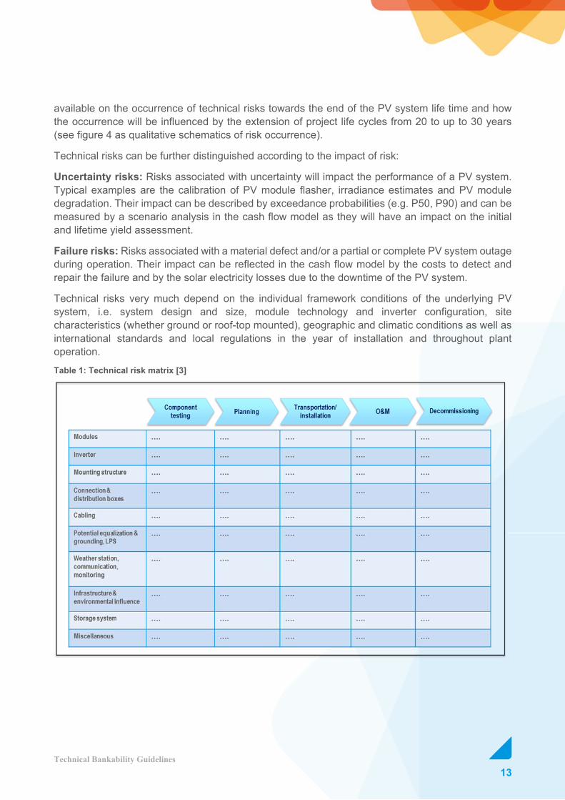
Table 1: Technical risk matrix [3]

14Technical Bankability Guidelines
Technical risks can be mapped in a risk matrix with the main mechanical and electrical components of the PV system on one axis and the five different phases of the project life cycle on the other axis (see table 1). The Solar Bankability Report “Technical Risks in PV Projects” provides a detailed description of the risk matrix and identifies more than 140 specific technical risks.
Failure costs associated with technical risks are often backed by product warranties and performance guarantees. Two levels of recoverability have to be reflected:
Component/performance risks: Component and performance risks can be backed by product warranties and performance guarantees. Their recoverability will depend on the formulation of the respective warranty and guarantee conditions, the proof of failure requirements and the applicable jurisdiction.
Contracting party/supplier risks: Product warranties and performance guarantees must be backed by the respective contracting parties/suppliers. The recoverability will depend on the track record, profitability and ongoing operations of the respective parties. Claiming of warranty and guarantee costs can get complex and time-consuming if more than one jurisdiction is involved.
The PV industry is rather young, still highly innovative and shows a rather cyclical business behaviour. Compared to more matured industries such as automotive, the degree of quality management and standardisation along the entire PV value chain from component testing, production through design, installation and operation as well as decommissioning is much less advanced and often contains uncharted gaps.
Gap risks: In current industry practices technical gaps can still be identified along all phases of a PV project. International PV standards and regional building and grid codes need to be adopted. The specification of failures and appropriate testing methods need to be further developed. Results at standard testing conditions in the laboratory need to be translated into performance at actual field conditions.
Important technical gaps are addressed in the Solar Bankability report “Review and Gap Analysis of Technical Assumptions in PV Electricity Costs” [4].

15Technical Bankability Guidelines
3. Risk Identification The identification of PV project risks is ideally carried out by an experienced technical expert from an independent third party. The scope of the risk analysis depends on the size of the project and the associated investment volume. It can vary from a full-fledged due diligence for a large utility-scale project to a red flag report for a commercial project or just a simple check list for a residential system.
The risk analysis should cover the entire project life cycle from project design and engineering, component procurement, installation, commissioning, operation and decommissioning. The most effective mitigation measure is the prevention of technical risks followed by the detection of technical risks as early as possible in order to avoid material defects, performance losses and potential personal hazards during the following phases of the project.
The risk identification process will depend on the technology, the type and the location of the PV project and might vary considerably between i.e. a ground-mounted PV utility project in Southern Italy or a roof-top residential PV system in Northern Germany. The process must be adopted to national standards, building codes and local craftsmanship regulations.
Utility/commercial PV projects: The scope of work for a full-fledged due diligence of large-scale PV projects might include a review of the design and engineering, component testing of modules, potential production audits at the module and inverter suppliers, audits during installation and commissioning, ongoing performance monitoring during operation and regular PV plant audits.
Risk identification for large-scale PV projects has reached a professional level and it pays off for the investor to allocate a sufficiently large budget early in the project and throughout operation. Several best practice guidelines and checklists have been developed in recent years. The Solar Bankability report “Best Practice Guidelines for PV Cost Calculations” contains three main checklists [6]:
1. Best Practice Checklist for EPC Technical Aspects (Appendix 1)
2. Best Practice Checklist for O&M Technical Aspects (Appendix 2)
3. Best Practice Checklist for Long-Term Yield Assessment (Appendix 3)
Three supplementary checklists are:
4. Checklist for As-Build Documents – Type and Details
5. Checklist for Record Control
6. Checklist for Reporting Indicators
A selection of further best practice guidelines and checklists from other sources has been included in the reference list [7,8,9,10,11,12].
Residential PV projects: In the past, residential PV roof-top systems were often sold under the umbrella of a risk-free and safe financial investment. Therefore, private house owners used to have little or no risk awareness. In some cases, these systems were installed under time pressure without

16Technical Bankability Guidelines
adequate PV training, qualification of staff and proper documentation. Like any other electrical installation, PV systems are subject to regular wear and ageing. Existing and newly formed trade and industry associations needed a couple of years to close the existing gaps of missing PV specific standards and regulations as well as to adopt their qualification and documentation requirements.
The German PV market serves as good example to illustrate these developments. As early as 2006 the “RAL Quality Assurance Association” introduced the PV quality label RALGZ 966 presenting standards for testing of PV components, design of PV systems, installation of PV systems, service and maintenance of PV systems and a check list for the commissioning of PV plants [13]. Unfortunately, only few of the early PV installers followed the voluntary commitment and the market penetration of the RAL PV label remained limited. In 2008, the German Solar Association BSW in cooperation with the Central Chamber of Electronics and Information Technology Trade ZVEH launched the “PV Passport” to check and document the design and installation of PV systems at the time of commissioning [14]. Until 2012 more than 1000 installers signed up for the PV Passport programme. In 2012, ZVEH launched the recurring “e-Check” PV Programme to complement the primary check-up of PV systems with a recurring check-up at a maximum recommended interval of four years [15]. In 2014, BSW in cooperation with ZVEH published the “PV Storage Passport” to account for the increasing number of PV systems with battery storage [16]. In 2016, the Quality Association for Solar and Roofing Technology (QVSD) introduced a quality check list for PV roof-top systems, which also covers technical risks associated with the interface of PV system and roofing system [17]. Combined market penetration of all these quality assurance schemes is estimated to be less than 10% for all new residential PV systems, which were installed in Germany in 2016. Many private house owners are still not aware that operators are legally responsible for the proper maintenance of electrical systems including PV systems. Industry and trade associations, consumer protection agencies, financing banks and insurances should support further market penetration of PV system check-ups and help to reduce technical risks associated with residential PV systems. This is especially important for safety issues.
An English version of the PV passport can be found in Appendix 4 of this report. The other checklists are only available in German and can be looked up under the respective reference number.
Contracting parties: An assessment of all contracting parties is essential in the risk identification process to ensure that the PV project will be backed by high quality components, professional workmanship and recoverable guarantees and warranties.
For utility/commercial PV projects the EPC, main component suppliers and the O&M (operation and maintenance) contractor should meet the following criteria (table 2):

17Technical Bankability Guidelines
Table 2: Criteria for PV contractor risk identification [1]
For residential PV systems, the qualification of the installer should include electrical, mechanical, structural and roofing know-how and expertise. Only a minority of residential PV systems are properly documented in a comprehensive check list during commissioning. For most of these systems, an O&M contract with a regular check-up schedule is missing. An online monitoring system, which allows for a timely detection of failures and system outages, is therefore highly recommended.
The design, installation and operation of residential PV systems require specific skills from different trade associations. Therefore, special attention should be payed to potential gaps as described in table 3:
Table 3: PV system skills vs. industry/trade associations in Germany

18Technical Bankability Guidelines
4. Risk Assessment The research work in the Solar Bankability project pursues the objective to assess the economic impact of technical risks on various business models, their levelised cost of electricity and their profitability.
Year 0 risks: Year 0 risks during the planning phase of the PV project, such as irradiation estimates or PV module degradation, with an associated uncertainty have a direct impact on the utilisation factor and energy yield. Their economic impact can be assessed by a scenario analysis taking into account different exceedance probabilities. A detailed analysis of yield exceedance probabilities e.g. P50 or P90 can be found in the Solar Bankability report “Minimizing Technical Risks in Photovoltaic Projects” [22].
Risks during operation: Once the risks during operation materialise, they turn into failures and the associated economic impact can be assessed. In the Solar Bankability project two alternative methods have been analysed. The report “Technical Risks in PV Projects” provides a top-down statistical approach based on a “Cost Priority Number” or CPN [3]. The report “Financial Modelling of PV Risks” introduces a business model specific bottom-up approach [18].
The CPN method builds upon the parameters used in FMEA analysis such as the severity (S), the occurrence (O) and the detectability (D) of failures over a given timeframe and determines related costs due to downtime/power loss and repair/substitution:
= + [€/kWp/year]
whereas cdown cost of downtime of the component, cfix cost of fixing the failure.
More than 1 million failure cases in 746 PV plants with an installed capacity of around 422 MWp have statistically been evaluated to determine the Cost Priority Number in Euro per kWp and year for each technical risk. The data base allows to differentiate CPN numbers according to different market segments and system locations.
The respective report provides CPN for modules, inverters, mounting structure, cabling and combiner boxes (an example of CPN for PV modules is given in figure 5).

19Technical Bankability Guidelines
Figure 5: Top 10 CPNs for PV modules based on utility-scale PV projects
For the financial modelling of PV risks a detailed bottom-up approach based on actual failure costs for four different business models, two residential and two utility-scale models, in Germany, Italy and the UK have been evaluated to assess the economic impact on the respective cash flow models. In analogy to the CPN method, the severity, occurrence and detectability have been evaluated in a detailed calculations of the cost associated with each failure:
= + [€]
whereas cfail cost of failure.
Different failure categories have been introduced to classify the economic impact on the cash flow model. The categories compare the failure impact with the 12 month revenues of the PV project in the first year of operation. The category structure follows the debt reserve account of 3, 6 or 12 months often required by banks in project financing to cover unpredicted project risks (figure 6).

20Technical Bankability Guidelines
Figure 6: Definition of failure categories [18]
The DiaCore study on “Risks in Renewable Energy Investments” [19] shows that technical risks represent only one dimension in an overall risk assessment. And that technical risks are of subordinate importance compared to other risks such as:
- Administrative risk,
- Grid access risk,
- Market design & regulatory risk,
- Policy design risk,
- Financing risk,
- Social acceptance risk,
- Sudden policy change risk.
In the rating methodology of professional rating agencies like Moody’s, only 20% of the overall weight is allocated to the technical risks in power generation projects [20].

21Technical Bankability Guidelines
5. Risk Management The planning of a PV project should be complemented by a professional risk management plan. The plan should contain measures to prevent initial risks, to reduce their potential occurence/impact and to transfer risks to other parties so that the residual risks, which have to be borne by the investor, can be minimised (figure 7).
Figure 7: Potential risk management plan [21]
5.1 Risk Mitigation There are two main categories of mitigation measures to prevent and reduce the potential occurence and impact of initial risks.
Preventive measures: They are applied before the risk occurs in order to prevent it from happening. Due to early implementation, their costs are mostly related to CAPEX.
Corrective measures: They reduce higher losses and costs once the risk has already occurred. Their costs are mostly related to OPEX.

22Technical Bankability Guidelines
A list of all relevant risk mitigation measures is included in the Solar Bankability report “Minimising Technical Risks in Photovoltaic Projects” (table 4) [22]:
Table 4: List of mitigation measures with description
Mitigation measure Description
PV plant planning The planning of a PV plant requires taking assumptions of a set of input parameters in order to predict its final yearly energy production and its lifetime performance. This is usually done using specific software. Each input has a given uncertainty, depending on the availability and quality of the information that the planner has. PV projects, whose simulations are run in a context of little information on the input parameters, have the highest uncertainties of the output values, and therefore are more risky and is less attractive for PV investments.
Reducing uncertainty (irradiation)
Some of the main technical risks in lifetime energy yield calculations arise from the uncertainties related with the solar resource quantification and its long-term behaviour. These uncertainties affect directly the business plan and the investment decision can be compromised. Therefore, reducing these uncertainties can help to make the investment of the PV system more attractive.
Reducing uncertainty (temperature)
Use temperature coefficients or Ross coefficients from laboratory measurements or extrapolated from existing plants in similar conditions. When applying models to translate the available series of ambient temperature, use models that take also the influence of wind on module performance into consideration.
Reducing uncertainty (degradation)
Consider available research results on typical values of degradation rates according to technology and climate. Include spectral effects in modelling if possible to further reduce uncertainty.
Component testing High-quality photovoltaic modules are subject to a number of requirements. First, they have to deliver the guaranteed rated power reliably. At the same time, the modules must be able to withstand an extremely wide range of environmental conditions. The modules must also be safe and durable, ensuring the system’s high yield over the long- term period. With component testing, the quality of the modules can be fully certified.
Design review + construction monitoring
The total number of detected failures due to wrong design or installation in the Solar Bankability database highlights the importance of this measure. In order for the PV project to meet the expectations of the investors regarding the profitability and life expectancy a number of actions have to be taken. Risks such as underperformance, warranty coverage, delay, cost overrun etc. are minimised after the application of this measure.

23Technical Bankability Guidelines
In a cost benefit analysis, the impact of potential mitigation measures should be assessed along the life cycle of the project.
Mitigation measure Description
Qualification of EPC
The qualification of EPC (engineering, procurement and constructions) is a preventive mitigation measure that will reduce the risk at an early stage of the PV project phase. EPC personnel shall have a high educational level as well as appropriate technical knowledge. Regular training schemes should be designed and available to EPC personnel for maintaining the high quality of staff and service provision.
Advanced monitoring system
An advanced monitoring system allows the early detection and diagnosis of faults. Early detection and diagnosis of faults during PV plant operation are essential in order to obtain and maintain the energy yield high. Early remediation of faults not only restores generation promptly but also avoids the occurrence of additional component failures and leads to reduction of O&M costs. The benefit of advanced monitoring is built up through reduced operational costs on one hand and additional revenues resulting from a higher performance ratio and higher availability on the other hand.
Basic monitoring system A basic monitoring system typically allows the monitoring on plant level including device alarm collection and notifications. Furthermore, aggregation functionality on plant level for energy, irradiation and performance ratio are typically provided.
Advanced inspection Advanced inspection relies on the use of techniques which go beyond visual inspection such as infrared imaging (IR) and electroluminescence imaging (EL), IV string analyser, etc.
Visual inspection Visual inspection can establish whether any visual changes are occurring that may affect the performance of the principal components or reduce the effective life of the system or components providing data needed for planning maintenance and operation requirements. Through visual inspection technical risks with high occurrence can be typically detected (inverter polluted air filter, PV module glass breakage, broken connectors, etc).
Spare parts management Spare parts management is a mitigation measure which has an impact in the initial investment and can be applied to several components of a PV plant. An effective spare parts management ensures the availability of the right amount and type of components, equipment, parts, etc. either on site or in warehouses or in manufacturers’ consignment stocks, for prompt replacement in case of failure and/or to meet guarantees under O&M contracts.

24Technical Bankability Guidelines
Two Solar Bankability reports provide a detailed analysis of risk mitigation scenarios consisting of single measures or a combination of measures. They come to the conclusion that preventive measures applied as early as possible in the project life cycle have the highest positive impact. Most effective measures are component testing, design review, qualification of EPC and monitoring systems for advanced fault detection [6, 21].
5.2 Risk Transfer The ultimate responsibility of risks lies with the owner and operator of the PV project. However, through contracts, guarantees, warranties and insurances some of the risks can be transferred to other parties. The risks should be allocated to those parties, which have the best control of each risk (figure 8):
Figure 8: Transfer of technical risks
EPC/Installer: An EPC/installer contract should clearly specify the scope of work and the responsibilities of the EPC/installer during the engineering, procurement and construction phase of the PV project. The “Best Practice Checklist for EPC Technical Aspects” in Appendix 1 provides an overview of the items which should be considered in the contract. The services of the EPC/installer should be validated during commissioning of the PV system. The EPC/installer can be held

25Technical Bankability Guidelines
responsible for any material defect and/or workmanship failure during the warranty period. Depending on the type of contract and the national legal framework, the warranty period varies between one and two years [4]. In some cases, it can even reach five years. An on-site audit of the PV system is highly recommended prior to the expiration of the warranty period.
O&M: Most commercial and utility-scale PV systems are covered by an O&M contract. The O&M contract should clearly specify the scope of work and the responsibilities of a potential O&M contractor during the operational phase of the PV project. The “Best Practice Checklist for O&M Technical Aspects” in Appendix 2 provides an overview of the items which should be considered in the contract. The O&M contractor can be held responsible for any material defect and/or workmanship failureduring the warranty period of services and materials provided by him. Many residential PV systems, however, lack any third party service and maintenance. Their owners have to be aware and comply with any legal or insurance requirements with respect to the operation, regular services and maintenance of the respective PV systems.
Component manufacturer: In most PV projects there is a supply contract between the component manufacturer and the EPC/installer. A direct supply contract with the investor is rather exceptional. Therefore, any claims against the manufacturer are usually handled indirectly via the EPC/installer. During the warranty period the manufacturer can be held responsible for any material and/or workmanship failures of his products. Tier one manufacturers often offer a voluntary extension of the legally required warranty period. This voluntary warranty period currently ranges between 10 to 12 years for PV modules and between 5 to 10 years for inverters. In addition to the product warranty, module suppliers normally offer a performance guarantee which ensures 90% of the name plate performance up to 10 years and 80% up to 25 years.
Historically, warranty and guarantee conditions were supply-side driven. In many cases it was not easy for investors to claim their warranty or performance guarantee. In recent years, consumer protection agencies have made several attempts to ensure bettert conditions for the investors. Investors should pay attention to the following potential pitfalls:
• The warranty and guarantee conditions should be clearly defined. Relevant criteria and potential test methods should be unambiguously specified and easy to implement.
• There is a potential conflict of interest in cases where the same contractor is responsible for the EPC/installer and the O&M service. An independent third party should carry out a PV plant audit before the end of the EPC/installer warranty period.
• A misalignment in the duration of the EPC/installer’s and the component manufacturer’s warranties might lead to potential conflicts. A longer EPC/installer and a shorter component manufacturer’s warranty period might force the EPC/installer into bankruptcy.
• Favourable manufacturer’s product warranty and guarantee conditions should cover the costs of dismantling, shipping, testing and disposal of worn-out products and the installation of the new product.

26Technical Bankability Guidelines
• Favourable manufacturer’s product warranty and guarantee conditions should not only pay for the remaining value of the defective product, they should rather offer the replacement of the defective product by a new product and the compensation of potential production losses.
• The follow-up of warranty and guarantee claims is time, effort and cost consuming. In cases, in which international parties are involved, the complexity can significantly increase due to the involvement of multiple legislations.
• Investors should pay attention to potential contracting party risks. An increasing number of bankruptcies along the value chain of the PV industry have rendered potential warranty and guarantee conditions void.
Insurance: Insurance coverage for technical risks is available both during the project contraction and operational phase. The former phase can be covered by a general liability and a construction insurance. The latter phase can be covered by a general liability, a property damage, a business interruption, and optionally by a performance guarantee insurance. The coverage is offered for technical risks caused by external root causes such as storm, external surges, fire, theft, etc. Usually, the insurance includes a deductible which the PV system owner has to cover himself. The business interruption insurance covers revenues lost on power feed-in for the duration of a breakdown of up to 12 months. In recent years, insurers started to differentiate insurance premiums between new and used PV systems, with significantly higher premiums for aged PV systems. In case of an insurance claim, the insurer usually reserves the right to cancel the insurance.
Investor: The investor in his role as owner and operator of the PV system has to bear all residual risks throughout the life cycle of the PV system, which are not covered by warrantees, guaranties or insurances. Therefore, the investor should take an active role in the assessment of technical risks and not rely on the bankability assessment of the debt financing bank.
Bank: The bank bears the credit default risk during the pre-financing and the financing phase of a PV project. Usually, a thorough bankability assessment is performed to identify all relevant potential project risks. The risk structure of the project is reflected in the credit terms. The leverage ratio, the credit duration, the debt service reserve account and the interest rate are adjusted accordingly. In case any of the credit covenants are breached, the bank reserves the right to cancel the credit agreement.

27Technical Bankability Guidelines
6. Risk Control In the aftermath of the financial crisis in the year 2008, new capital market requirements have been developed for institutional investors from the banking, insurance and investment funds industry in order to enhance the transparency and stability in global capital markets [18]. The new capital market framework is based on three pillars (figure 8) [23]:
• Pillar I: Enhanced minimum capital and liquidity requirements,
• Pillar II: Enhanced supervisory review process for firm-wide risk management and capital planning,
• Pillar III: Enhanced risk disclosure and market discipline.
Figure 9: Three pillar model on new capital markets’ regulations
In a harmonised effort, financial regulatory bodies on a global, European and national level have developed a set of regulations for each capital market sector:
• Banking (Basel III),
• Insurance (Solvency II),
• Investment Funds (UCITS V / AIFM).
The regulations require institutional investors to introduce a hierarchically independent risk management function. This function is in charge of the firm-wide risk management including an ongoing risk controlling and a transparent risk reporting at least once a year. Institutional investors

28Technical Bankability Guidelines
can either enhance their own risk management organisation and build up an in-house team specialised in PV risk assessment or they can access external rating services, which are being offered by specialised consulting firms or international rating agencies.
The checking of technical risks for large commercial and utility-scale PV projects is often transferred to specialised owner’s engineers. They ensure the professional supervision of the engineering, construction and commissioning of the PV plant and provide an ongoing risk monitoring during the operational phase with regular risk reporting at least once a year.
For residential PV systems the owner is responsible for the risk management. Most of these systems are not covered by a regular service and maintenance contract. Therefore, a regular check-up of the PV system is recommended at least every four years for PV systems equipped with an online monitoring system. For systems without an online monitoring system, the check-up intervals should not exceed two years [17] .

29Technical Bankability Guidelines
References [1] Hampel,N., Lüdeke-Freund,F., e.a., "The Myth of Bankability", [Online] Available from:
https://www.goetzpartners.com/uploads/tx_gp/Studie_Bankability_final.pdf [Accessed: 01-Dec-2016]
[2] IRENA, "Quality Infrastructure for Renewable Energy Technologies“, [Online] Available from: http://www.irena.org/DocumentDownloads/Publications/IRENA_QI_1_PM_Guide_2015.pdf [Accessed: 01-Dec-2016]
[3] Moser,D., Del Buono,M., e.a., "Technical Risks in PV Projects", [Online] Available from: http://www.solarbankability.eu [Accessed: 19-Aug-2016]
[4] Tjengdrawira,C., Richter,M., e.a., "Review and Gap Analysis of Technical Assumptions inn PV Electricity Cost", [Online] Available from: http://www.solarbankability.eu [Accessed: 19-Aug-2016]
[5] Hense, V., "PV-Anlagen – Fehler erkennen und bewerten", Köln, TÜV Media GmbH, 2015
[6] Tjengdrawira,C., Richter,M., e.a., "Best Practice Guidelines for PV Cost Calculation", [Online] Available from: http://www.solarbankability.eu [Accessed: 01-Jan-2017]
[7] SolarPower Europe, “O&M Best Practice Guidelines,” Solar Power Europe, Public report Version 1.0, Jun. 2016.
[8] IFC, “Utility-Scale Solar Photovoltaic Power Plants: A project Developer’s Guide,” International Finance Corporation, Washington, D.C. 20433, Public report, 2015.
[9] Doyle,C., Loomans,L., e.a., “SAPC - Best Practice in Commercial and Industrial Solar Photovoltaic System Installation”, [Online] Available from: www.nrel.gov/docs/fy16osti/65286.pdf [Accessed: 12-Dec-2016]
[10] Doyle,C., Truitt,A., e.a., “SAPC - Best Practice in PV System Operations and Maintenance”, [Online] Available from: www.nrel.gov/docs/fy15osti/63234.pdf [Accessed: 12-Dec-2016]
[11] Keating,T.J., Walker,A., e.a., “SAPC - Best Practice in PV System Installation”, [Online] Available from: www.nrel.gov/docs/fy15osti/63235.pdf [Accessed: 12-Dec-2016]
[12] Sengupta,M., Habte,A., e.a., “Best Practices Handbook for the Collection and Use of Solar Resource Data for Solar Energy Applications”, [Online] Available from: www.nrel.gov/docs/fy15osti/63112.pdf [Accessed: 12-Dec-2016]

30Technical Bankability Guidelines
[13] RAL Gütegemeinschaft für Solarenergieanlagen e.V., “Güte- und Prüfbestimmungen (RAL-GZ 966)”, [Online] Available from: http://www.ralsolar.de/download/RAL-GZ_966_August_2008.pdf [Accessed: 12-Dec-2016]
[14] Bundesverband Solarwirtschaft e.V., “PV Passport”, [Online] Available from: https://www.solarwirtschaft.de/fileadmin/user_upload/pv_passport_document.pdf [Accessed: 10-Jan-2017]
[15] Zentralverband der Deutschen Elektro- und Informationstechnischen Handwerke GbR, “e-Check PV”, [Online] Available from: http://www.e-check.de/privat/e-check-pv.html [Accessed: 12-Dec-2016]
[16] Bundesverband Solarwirtschaft e.V., “Photovoltaik-Speicherpass”, [Online] Available from: http://www.photovoltaik-anlagenpass.de/der-speicherpass/ [Accessed: 12-Dec-2016]
[17] Qualitätsverband Solar- und Dachtechnik e.V., “Qualitätsmerkblatt Photovoltaik-Anlagen”, QVSD, München, 2017
[18] Armansperg, M., Oechslin, D., Schweneke, M. “Financial Modelling of PV Risks”, [Online] Available from: http://www.solarbankability.eu [Accessed: 01-Dec-2016]
[19] Noothout, P.,de Jager, D., Tesniere, L., e.a., “The Impact of Risks in Renewable Energy Investments and the Role of Smart Policies”, Freiburg, Fraunhofer ISI, 2016 (DiaCore Project)
[20] Donner, R., Berckmann, C., Sabatelle, A., “Rating Methodology – Power Generation Projects”, New York, Moody’s Investors Service, 2012
[21] Böttcher, J., “Solarvorhaben – Wirtschaftliche, technische und rechtliche Aspekte”, Oldenbourg Verlag, München, 2012
[22] Jahn, U., Moser, D., Richter, M., e.a., “Minimising Technical Risks in Photovoltaic Projects”, [Online] Available from: http://www.solarbankability.eu [Accessed: 01-Dec-2016]
[23] Basel Committee on Banking Supervision, "Basel III Summary Table," [Online] Available from: http://www.bis.org/bcbs/basel3/b3summarytable.pdf [Accessed: 22 July 2016]

31Technical Bankability Guidelines
Appendices Appendix 1: Best Practice Checklist for EPC Technical Aspects
/ Technical aspect & what to look for in the EPC contract
A Definitions, interpretation
1. Is there a set of definitions of important terms provided and are those clear and understood by all stakeholders?
B Contractual commitments
2. EPC contractor qualification
3. Responsibility and accountability
4. Date of ownership and risk transfer are defined and acceptable
5. Construction start date and end date are defined and acceptable
6. Plant Commercial Operation Date (COD) is defined and in line with FiT or PPA commencement dates
7. The EPC works should be carried in compliance with (non-exhaustive list)
• Grid code compliance: plant controls (e.g. ability for emergency shut-downs or curtailment according to grid regulations)
• PPA compliance
• Building permits (if applicable)
• Environmental permits
• Specific regulation for the site (e.g. vegetation management, disposal of green waste)
C Scope of work – engineering
8. Overall the scope of works for the EPC should be clearly defined. Which activities are included in the EPC services (is it a turnkey EPC)? Are they clearly defined?
9. The EPC should include Technical Specifications consisting of
• [Best practice] The operating environment is defined for:
o Minimum and maximum ambient temperature
o Maximum relative humidity
o Maximum altitude
o Local climate
o Local conditions (e.g., snowy, sandy, near sea/chemical source/corrosive/agricultural activity/purpose of building usage/etc.)
• Detail plant description on all major components including MV/HV equipment, monitoring, meteo stations, security and surveillance

32Technical Bankability Guidelines
• Plant implantation schematic including not only the major components but also auxiliaries (electrical cabinet, substations etc.) and facilities (storage, office, guard house, fences, road access etc.)
• Single wire diagram
• Bill of materials of the major components
• Recommended minimum spare part lists (draft version of this information during EPC negotiation should be updated to the final version when the plant is completed and handed over)
• [Best practice] List of all applicable technical standards for major components (panels, inverters, electrical equipment) (non-exhaustive list)
o CE Compliance
o Panel: IEC61215, IEC61730, IEC61701, IEC62716, IEC62804, IEC62108 (CPV)
o IR/EL: IEC60904-12 & 13
o Inverter: IEC62109
o Electrical equipment: IEC61000
o Tracker: IEC62817, IEC62727
o Design and installation: IEC TS 62548
o Commissioning: IEC62446
o Performance monitoring: IEC61724
10. Who is responsible for grid connection and the infrastructure to connect the PV plant to the grid (transformer, export lines, substation) is clearly defined
11. Site suitability (ground installation)
• Geotechnical and soil study
• Any flood risk
• Other constraints (chemical in the air, corrosive air, etc.)
Site suitability (rooftop installation)
• Roof stability study
• Structural requirements of roof and mounting structure (both static/snow load and dynamic/wind load
• Lightning protection requirement
• Fire protection (PV system should not be built across fire protection walls); design should be in compliance with the building fire protection codes
• Requirement for weathering protection (lifetime of roofing film)
12. If the site study has been done and the results have been shared with the owner and the EPC, the EPC contract should clearly acknowledge that the contractor has reviewed the results of the study and has designed the PV system taking into account the site conditions and constraints

33Technical Bankability Guidelines
13. For rooftop system, the roof should be weatherproof throughout operations of PV plant without major overhaul of roof laminate layer
14. Estimation of plant yield/production should follow best practice guidelines (see Annex C.3)
15. The plant design and estimated yield/production should be validated by third party
D Scope of work – procurement
16. All major components should be visually inspected at delivery
17. All modules should be tested for STC performance according to the IEC60904 standards at the factory and the test data should be submitted to the EPC contractor for verification
[Best practice] All modules should be inspected with electroluminescence imaging camera at the factory and the test data should be submitted to the EPC contractor for verification
18. PV modules should be sampled and tested after delivery and before acceptance
• List of test (and criteria) should be included in the EPC contract
• Tests are to be done by an accredited independent test laboratory
19. [Best practice] Transportation and handling requirements on components should be specified
20. [Best practice] EPC contractor is required to perform factory inspection on the module factory
21. [Best practice] Negotiation of technical requirement in supply agreement (i.e. module) and warranty terms and conditions should involve inputs from technical advisors
E Scope of work – construction
22. The EPC should include comprehensive protocol and training to its field workers on how to un-package and handle components properly
23. The installation of components should adhere the manufacturer’s guidelines when applicable
24. Regular construction monitoring by the owner (assisted by technical advisor) should be performed to check construction progress and quality (and for milestone payments)
25. Reporting of construction progress should be included in the contract
26. Health and safety, housekeeping and site security are defined as the responsibilities of the contractor during construction
F Scope of work – administrative and others
27. Responsible party for securing the site use is clearly defined:
• For ground-mounted utility systems: land lease, land purchase, and land access
• For commercial rooftop systems: roof lease, roof access
28. Responsible party to obtain permits and authorizations to develop PV plant is clearly defined
29. Any support required from the EPC contractors in permitting, grid connection etc. should be clearly defined
30. Is the contractor responsible to carry out or only support warranty and insurance claims management during the EPC period?
G Manufacturer warranties

34Technical Bankability Guidelines
31. The terms and conditions of major components’ manufacturer warranties are clearly defined
• Effective start and end date
• Definition of defects
• Claim procedure
• The compensations proposed are reasonable and logical
• Exclusions
• Provision to allow for the involvement of third party expert during technical dispute
• Transferability
32. The warranty timelines should be in line with the EPC warranty timelines
33. Check if the jurisdiction of the warranty allows it to be legally enforceable
34. [Best practice] Are there additional insurances (transportation damages, e.g.) from either the EPC contractor or component manufacturer?
H EPC warranty and Defect Liability Period (DLP)
35. Provide warranty of Good Execution of Works
36. The EPC contract shall provide at minimum 2-year EPC warranty from the date of plant take-over
37. The DLP duration coincides with the EPC and component manufacturer warranty duration
38. During this DLP, the EPC contractor is responsible to repair faults or defect at its own cost, or an arrangement has been made with the O&M contractor to execute this. For the latter, clear scope of work ownerships must be aligned to prevent avoidance of responsibilities
39. The party responsible to maintain the PV plant after take-over and before the end of DLP is clearly defined
I Key performance indicators (KPIs) and guarantees
40. The EPC contract should have key performance indicators for two aspects
• Completion timeline: guaranteed completion date
• System performance and quality: guaranteed performance ratio (PR) or guaranteed output
41. The guaranteed PR or output should be calculated in a long-term yield estimation exercise using correct technical assumptions, i.e. all relevant losses and uncertainties
42. Liquidated damages (LD) or penalties should be assigned in the contract in case the guaranteed KPIs are not met
43. Completion delay LDs should be in line with the project revenue loss due to lateness in project entering operation. The LD is commonly a % of EPC price for each day of delay
44. Performance LDs should be in line with the project revenue loss when the system is not meeting the guaranteed performance level. The LD is commonly a % of EPC price for each point of PR or output below the guaranteed value
45. Maximum amount of LD (LD cap) to limit contractor’s liability is usually included in the EPC contract. E.g., delay LD and performance LD could each be capped at 20% of the EPC contract price and the combined cap is 30% of the EPC contract price

35Technical Bankability Guidelines
J Commissioning and acceptance
46. The EPC contract should include plant provisional and final commissioning
47. Short term performance test should be carried out after the PV system completes the construction phase
48. Provisional test set-up should include appropriate:
• Duration of the test
• Irradiance threshold
• Monitoring system, including measurement sampling rate and averaging method
49. The calculation method for the key performance indicator for provisional acceptance should account for short-term effect on temperature and irradiance
50. Final acceptance plant performance should be carried out after the plant has been in operation for a representative period of time (2 years after provisional acceptance)
51. Final performance test set-up should include appropriate
• Irradiance threshold
• Monitoring system, including measurement sampling rate and averaging method
52. The calculation method for the key performance indicator for final acceptance should account for:
• Annual degradation
• Plant availability
53. Measurement of irradiance to assess plant performance
• Irradiance measurements
• Measurement in the POA according to the Secondary Standard or First Class quality classification (ISO9060:1990)
• Minimum requirement: one measurement device (pyranometer of high quality)
• [Best practice] At least 2 pyranometers
• If different array orientations, one pyranometer per orientation – careful assignment for proper calculation of PR and yield
• Sensors placed at the least shaded location
• Sensors installed according to manufacturer’s guidelines
• Preventative maintenance and calibration according to manufacturer’s guidelines
• Set irradiance to be recorded with averages of 15 min (minimum requirement) or 1 min and less (best practice)
• High quality satellite-based data to complement terrestrial measurements [best practice] – mainly for monthly and annual values and not daily since the RMSE is high (8-14%)
• Minimum requirements for satellite data: hourly granularity or 15 min. Set data to be retrieved once per day at least
54. Measurement of irradiance to assess plant performance
• Temperature sensor properly installed according to manufacturer’s guidelines

36Technical Bankability Guidelines
• Use of stable thermally conductive glue to the middle of the backside of the module in the middle of the array, in the center of the cell away from junction box
• Accuracy should be <±1 C including signal conditioning
• For large systems, different representative positions for installing the sensor should be considered: module at the center of the array and at the edge of this module where temperature variations are expected
55. Inverter measurement to assess plant performance
• AC level: energy and power data should be collected
• Energy data should be cumulative values over the lifetime of the inverter
• Collect all inverter alarms – important to plan your maintenance activities (corrective and preventative)
• Monitor and manage control settings at the inverter level and the grid injection level
• DC input measurements <1s sampling and <1min averaging
• DC voltage to be measured and stored separately for allowing MPP-tracking and array performance problems
• [Best practice] measure all parameter from the inverters including internal temperature, isolation level etc.
56. Energy meter
• Collection of energy meter data by the monitoring system in daily basis and with 15 min granularity
• High accuracy energy meter is required – uncertainty of ±0.5% for plants >100 kWp
• The above point can be considered as best practice for plants smaller than 100 kWp
57. Plant visual inspection should be carried out during acceptance test
[Best practice] The visual inspection uses advanced tools such as IR camera
58. As part of the plant hand-over process, the EPC contractor must provide (non-exhaustive list)
• A complete set of as-build documentation (IEC62446, see Annex C.4 for complete set)
• Recommended minimum spare parts list

37Technical Bankability Guidelines
Appendix 2: Best Practice Checklist for O&M Technical Aspects
/ Technical aspect & what to look for in the O&M contract
A Definitions, interpretation
1. Is there a set of definitions of important terms provided and are those clear and understood by all stakeholders?
B Purpose and responsibilities
2. Is the fundamental purpose (goals) of the contract clearly defined?
3. Are the roles and responsibilities (and boundary conditions) of the multiple stakeholders within the contract clear and understood?
C Scope of works – environmental, health and safety Note: The Asset Owner has the ultimate legal and moral responsibility to ensure the health and safety of people in and around the solar plant and for the protection of the environment around it. The practical implementation is normally subcontracted to the O&M contractor.
4. Environment
• Regular inspection of transformers and bunds for leaks (according to the annual maintenance plan)
• Recycling of broken panels and electric waste
• Sensible water usage for module cleaning
• Proper environmental management plan in place
5. Health and safety (H&S)
• Properly controlled access and supervision in the solar plant – necessary boundaries and site restrictions
• Proper induction to ensure awareness of risks and hazards
• Proper training and certification on the specifics of a PV plant and voltage level
• Hazard identification/marking
• Wiring sequence marking
• H&S legislation available
• Established personal protective equipment (PPE) (not exhaustive list): safety shoes, high visibility clothing, helmet, gloves (and/or insulated gloves), slash masks and glasses (depending on the site), fire retardant and/or arc flash rated PPE where necessary
• Calibrated and certified equipment (full documentation available)
D Scope of works – operations
6. Documentation Management System (DSM)
• As-built documentation / IEC62446 (see Annex C.4)
o Site information
o Project drawings

38Technical Bankability Guidelines
o Project studies
o Studies according to national regulation requirements
o PV modules
o Inverters
o Medium voltage / inverter cabin
o MV/LV transformer
o HV switchgear
o UPS and batteries
o Mounting
• Management and control
o Define type of storage (physical or/and electronical)
o Ensure electronic copy of all documents
o Ensure controlled access to documents
o Ensure authorization for modifications – keep a logbook on name of person who modified the document, date of modification, reason for modification and further information e.g. link to the work orders and service activities
o Ensure history of the documents (versioning)
• Record control (see Annex C.5)
7. [Best practice] Predictive maintenance
• Define scope of this cluster, the type of performance analysis, the level (portfolio level, plant level, inverter level, string level)
• Define the monitoring requirements needed to perform predictive maintenance, provide basic trending and comparison functionality
8. Power generation forecasting
• Ensure a service level agreement with the forecast provider
• Define the purpose and consequently the requirements for power forecasting (e.g. time horizon, time resolution, update frequency)
9. Reporting (see Annex C.6)
10. Regulatory compliance
• Grid code compliance: plant controls (e.g. ability for emergency shut-downs or curtailment according to grid regulations)
• PPA compliance
• Building permits (if applicable)
• Environmental permits
• Specific regulation for the site (e.g. vegetation management, disposal of green waste)

39Technical Bankability Guidelines
11. Management of change: define responsibilities and involvement when PV plant needs to be adjusted after the Commercial Operation Date: e.g. spare parts, site operation plan, annual maintenance plan etc.
12. Warranty management
• Warranty of Good Execution of Works
• Warranty of Equipment
• Performance Warranty: agree on reporting period
• Classification of anomalies and malfunctions: Pending Works, Insufficiencies, Defects, Failure or malfunction of equipment
13. Insurance claims management
E Scope of works – maintenance
14. Inclusion of an adequate Preventive Maintenance Plan
15. The minimum requirements for preventative tasks and their frequency follow the manufacturer’s guidelines when applicable
16. The minimum requirements for preventative tasks and their frequency should respect relevant national standards
17. Corrective maintenance (CM)
• Fault diagnosis (troubleshooting)
• Repair and temporary repairs
• Agreed response times and/or minimum repair times
• Clear definition of “boarders” and “limitations” of CM tasks, especially with preventative maintenance and extraordinary maintenance. Definition of yearly cap of CM works (when applicable)
18. Extraordinary maintenance
• Define what is included in this cluster
o Damages that are a consequence of a Force Majeure event
o Damages as a consequence of a theft or a fire
o Serial defects on equipment, occurring suddenly and after months or years from plant start-up
o Modifications required by regulatory changes
o Agreed interventions for reconditioning, renewal and technological updating
• Define the rules on how to execute tasks and prepare quotations – ways of payment
19. Additional services: define what is included in this cluster and how this service is paid (non-exhaustive list)
• Module cleaning
• Vegetation management
• Road maintenance

40Technical Bankability Guidelines
• Snow removal
• Pest control
• Waste disposal
• Maintenance of buildings
• Perimeter fencing and repairs
• Maintenance of security equipment
• String measurements – to the extent exceeding the agreed level of preventative maintenance
• Thermal inspections – to the extent exceeding the agreed level of preventative maintenance
• Meter weekly/monthly readings and data entry on fiscal registers or in authority web portals for FiT tariff assessment (where applicable)
F Scope of works – data and monitoring
20. Irradiance measurements
• Measurement in the POA according to the Secondary Standard or First Class quality classification (ISO9060:1990)
• Minimum requirement: one measurement device (pyranometer of high quality)
• [Best practice] At least 2 pyranometers
• If different array orientations, one pyranometer per orientation – careful assignment for proper calculation of PR and yield
• Sensors placed at the least shaded location
• Sensors installed according to manufacturer’s guidelines
• Preventative maintenance and calibration according to manufacturer’s guidelines
• Set irradiance to be recorded with averages of 15 min (minimum requirement) or 1 min and less (best practice)
• High quality satellite-based data to complement terrestrial measurements [best practice] – mainly for monthly and annual values and not daily since the RMSE is high (8-14%)
• Minimum requirements for satellite data: hourly granularity or 15 min. Set data to be retrieved once per day at least
21. Module temperature measurements
• Temperature sensor properly installed according to manufacturer’s guidelines
• Use of stable thermally conductive glue to the middle of the backside of the module in the middle of the array, in the center of the cell away from junction box
• Accuracy should be <±1 C including signal conditioning
• For large systems, different representative positions for installing the sensor should be considered: module at the center of the array and at the edge of this module where temperature variations are expected
22. Local meteorological data

41Technical Bankability Guidelines
• [Best practice] Ambient temperature and wind speed with sensors installed according to manufacturer’s guidelines
• Ambient temp with shielded thermometer e.g. PT100
• Wind speed with anemometer at 10 m height above ground level
• For large plants >10 MW automated data from an independent nearby meteo source to smooth local phenomena and installation specific results
23. String measurements
• If not DC input current monitoring at inverter level, then current monitoring at string level is recommended – depending on module technology, combined strings (harnesses) can help reducing operating costs
• [Best practice] Increase up-time for timely detection of faults: 1 sec sampling and 1 min averaging at data logger, maximum two strings current measurement in parallel
24. Inverter measurement
• AC level: energy and power data should be collected
• Energy data should be cumulative values over the lifetime of the inverter
• Collect all inverter alarms – important to plan your maintenance activities (corrective and preventative)
• Monitor and manage control settings at the inverter level and the grid injection level
• DC input measurements <1s sampling and <1min averaging
• DC voltage to be measured and stored separately for allowing MPP-tracking and array performance problems
• [Best practice] measure all parameter from the inverters including internal temperature, isolation level etc.
25. Configuration
• In cases of change of O&M contractor (or recommissioning of the monitoring system), the configuration of the monitoring system and the data loggers should be checked
• [Best practice] if technically available, auto-configuration is recommended – e.g. automatic collection of inverter and sensor IDs and labels
• Back up of the configuration should be in place
26. Energy meter
• Collection of energy meter data by the monitoring system in daily basis and with 15 min granularity
• High accuracy energy meter is required – uncertainty of ±0.5% for plants >100 kWp
• The above point can be considered as best practice for plants smaller than 100 kWp
27. AC circuit / protection relay
• [Best practice] Monitor the AC switch position for (sub) plants. Read the alarms from the protection relay via communication bus if possible
28. Data loggers

42Technical Bankability Guidelines
• Sufficient memory to store at least one month of data
• Historical data should be backed up
• After communication failure, the data logger should resend all pending information
• The entire installation (monitoring system, signal converters, data loggers, measurement devices) should be protected by a UPS
• [Best practices] Memory to store at least six months of data and full data backup in the cloud. Separate remote server to monitor the status of the data loggers and inform the operations. The system should be an open protocol to allow transition between monitoring platforms. If possible, reboot itself once per day (during night time) to increase reliability
29. Alarms
• Minimum requirement: alarms sent by email (non-exhaustive list)
o Loss of communication
o Plant stop
o Inverter stop
o Plant with low performance
o Inverter with low performance (e.g. due to overheating)
• [Best practice] (non-exhaustive list)
o String without current
o Plant under UPS operation
o Intrusion detection
o Fire alarm detection
o Discretion alarm (or alarm aggregation)
30. Dashboard / web portal
• Minimum requirements for features of the monitoring system (non-exhaustive list)
o Web portal accessible 24h/365d
o Graphs of irradiation, energy production, performance and yield
o Downloadable tables with all the registered figures
o Alarms register
• [Best practices] (non-exhaustive list)
o User configurable dashboard
o User configurable alarms
o User configurable reports
o Ticket management
31. Data format
• Data format of recorded files according to IEC61724 – clearly documented
• Data loggers should collect alarms according to manufacturer's format

43Technical Bankability Guidelines
32. Communication from the site to the monitoring servers
• Best network connectivity with sufficient bandwidth according to the available monitoring system
• DSL connection preferred if available at the PV site – industrial routers recommended
• [Best practice] GPRS-connection as back up
• For sites >1 MW it is advised to have a LAN connection and as an alternative an industrial router that allows for GPRS or satellite communication back-up in case the LAN connection fails. A router with an auto-reset capability in case of loss of internet connection is recommended
• Data security should be ensured: as minimum requirements loggers should not be accessible directly from the internet or at least be protected via a firewall. Secure and restrictive connection to the data server is also important
• Communication cables must be shielded and protected by direct sunlight
• Physical distance between DC or AC power cables and communication cables should be ensured
• Cables with different polarities must be clearly distinguishable (label or color) for avoiding polarity connection errors
G Scope of works – spare parts management
33. Definition of ownership and responsibility of insurance
34. Define separate list of consumables if applicable (e.g. tools and fuses)
35. Stocking level: consider initial EPC list and the following parameters
• Frequency of failure
• Impact of failure
• Cost of spare part
• Degradation over time
• Possibility of consignment stock with the manufacturer
36. Location of storage/warehouse
• Proximity to the plant
• Security
• Environmental conditions
37. List of minimum spare parts (non-exhaustive list)
• Fuses for all equipment (e.g. inverter, combiner boxes etc.) and fuse kits
• Modules
• Inverter spares (e.g. power stacks, circuit breakers, contactor, switches, controller board)
• UPS
• Voltage terminations
• Power plant control spares

44Technical Bankability Guidelines
• Transformer and switchgear spares
• Weather station sensors
• Motors and gearboxes for trackers
• Harnesses and cables
• Screws and other supply tools
• Security equipment (e.g. cameras)
H Scope of works – plant security
38. Define protective measures for the plant
• Security protocol in place
• Video monitoring
• Alerting system
• Fencing or barriers
• Warning signs and notices
• Security pad codes and passwords
• Back up communication in case of vandalism
I Key performance indicators (KPIs)
39. Plant KPIs
• Availability
• Energy-based availability
• Performance Ratio
• Energy Performance Index
40. O&M contractor KPIs
• Reaction time
• Reporting
• O&M contractor experience
• Maintenance effectiveness and maintenance support efficiency
41. Security and surveillance of PV plant
• On-site or remote
• Around the clock coverage (24h/365d)
• On-site patrol, security camera
• On-site intervention time upon alarm etc.
J Contractual commitments
42. Qualification of parties involved: Owner’s Engineer, O&M contractor, monitoring, security firm
43. Responsibility and accountability
44. Bonus schemes and liquidated damages

45Technical Bankability Guidelines
Appendix 3: Best Practice Checklist for Long-Term Yield Assessment
/ Technical aspect & what to look for in the LTYA
A Solar resource assessment
1. Only reliable solar irradiation data sources should be used and the name(s) and version(s) must be clearly stated. Data source(s) used must be able to provide uncertainty estimations and ideally have been extensively validated
2. The period covered by the solar irradiation data source(s) used must be reported. Only data sources with more than 10-year recent data should be used for LTYA calculations
3. The effect of long-term trends in the solar resource should be analyzed. In the presence of such trends, the long-term solar resource estimation should be adjusted to account for this effect
4. The use of site adaptation techniques is recommended to reduce the uncertainty. A measurement campaign of at least 8 months and ideally one full year is recommended
B PV yield modelling
5. The PV modeling software and the specific version used must be clearly stated in the report
6. If in-house software is used, the name(s) and version(s) must also be stated
7. All assumptions (e.g. soiling losses, availability, etc.) and sub-models used (e.g. transposition model) must be clearly stated
C Degradation rate and behaviour
8. The degradation rate(s) used for the calculations must be clearly stated in the report. It is recommended to differentiate between first year effects and yearly behavior over project lifetime
9. Degradation behavior assumption (e.g. linear, stepwise, etc.) over time should be clearly stated and ideally backed up with manufacturer warranties
10. If specific manufacturer warranties are available (e.g. module warranty document or sales agreement), these can be used to fine tune the lifetime degradation calculation
D Uncertainty calculation
11. All steps in the long-term yield calculation are subject to uncertainties. All uncertainties should be clearly stated and references must be provided in the report
12. Special attention must be paid to the solar resource related uncertainties as these are among the most important elements in the contribution to the overall uncertainty
13. If special methods are used to reduce some uncertainties e.g. site adaptation techniques, these should be clearly documented and ideally backed up with scientific validation
14. Special care must be taken when classifying each uncertainty as either systematic or variable (stochastic) since these are treated differently in overall lifetime uncertainty calculations
15. When possible, exceedance probabilities (e.g. P90) for each uncertainty must be calculated using empirical methods based on available data instead of assuming normal distribution for all elements

46Technical Bankability Guidelines
Appendix 4: PV Passport

47Technical Bankability Guidelines

48Technical Bankability Guidelines

49Technical Bankability Guidelines

50Technical Bankability Guidelines

51Technical Bankability Guidelines

52Technical Bankability Guidelines

53Technical Bankability Guidelines

54Technical Bankability Guidelines

55Technical Bankability Guidelines

56Technical Bankability Guidelines

57Technical Bankability Guidelines

58Technical Bankability Guidelines

59Technical Bankability Guidelines

60Technical Bankability Guidelines
Funded by the Horizon 2020 Framework Programme of the European Union
This project has received funding from the European Union’s Horizon 2020 research and innovation programme under grant agreement No 649997. The content of this report reflects only the author’s view and the Commission is not responsible for any use that may be made of the information it contains.


