24
www.danfoss.com/ir Technical brochure Solenoid valves, two-step on/off PMLX MAKING MODERN LIVING POSSIBLE

www.danfoss.com/ir
Technical brochure
Solenoid valves, two-step on/offPMLX
MAKING MODERN LIVING POSSIBLE
2 DKRCI.PD.BR0.A2.02 / 520H0187 Danfoss A/S, (AC-SMC / MWA), 05 - 2011
Technical brochure Solenoid valves, two-step on/off, type PMLX
Contents Page
Introduction. . . . . . . . . . . . . . . . . . . . . . . . . . . . . . . . . . . . . . . . . . . . . . . . . . . . . . . . . . . . . . . . . . . . . . . . . . . . . . . . . . . . . . . .3
Features . . . . . . . . . . . . . . . . . . . . . . . . . . . . . . . . . . . . . . . . . . . . . . . . . . . . . . . . . . . . . . . . . . . . . . . . . . . . . . . . . . . . . . . . . . . .3
Design . . . . . . . . . . . . . . . . . . . . . . . . . . . . . . . . . . . . . . . . . . . . . . . . . . . . . . . . . . . . . . . . . . . . . . . . . . . . . . . . . . . . . . . . . . . . .4
Technical data . . . . . . . . . . . . . . . . . . . . . . . . . . . . . . . . . . . . . . . . . . . . . . . . . . . . . . . . . . . . . . . . . . . . . . . . . . . . . . . . . . . . . .4
Design / Function. . . . . . . . . . . . . . . . . . . . . . . . . . . . . . . . . . . . . . . . . . . . . . . . . . . . . . . . . . . . . . . . . . . . . . . . . . . . . . . . . . .5
Material specification . . . . . . . . . . . . . . . . . . . . . . . . . . . . . . . . . . . . . . . . . . . . . . . . . . . . . . . . . . . . . . . . . . . . . . . . . . . . . . .7
Flange connections . . . . . . . . . . . . . . . . . . . . . . . . . . . . . . . . . . . . . . . . . . . . . . . . . . . . . . . . . . . . . . . . . . . . . . . . . . . . . . . . .9
Ordering of PMLX valves - Complete valves . . . . . . . . . . . . . . . . . . . . . . . . . . . . . . . . . . . . . . . . . . . . . . . . . . . . . . . . 11
Accessories . . . . . . . . . . . . . . . . . . . . . . . . . . . . . . . . . . . . . . . . . . . . . . . . . . . . . . . . . . . . . . . . . . . . . . . . . . . . . . . . . . . 12
Dimensions and weights . . . . . . . . . . . . . . . . . . . . . . . . . . . . . . . . . . . . . . . . . . . . . . . . . . . . . . . . . . . . . . . . . . . . . . . . . . 14
Nominal capacities . . . . . . . . . . . . . . . . . . . . . . . . . . . . . . . . . . . . . . . . . . . . . . . . . . . . . . . . . . . . . . . . . . . . . . . . . . . . . . . 15
Wet suction line. . . . . . . . . . . . . . . . . . . . . . . . . . . . . . . . . . . . . . . . . . . . . . . . . . . . . . . . . . . . . . . . . . . . . . . . . . . . . . . 15
Dry suction line . . . . . . . . . . . . . . . . . . . . . . . . . . . . . . . . . . . . . . . . . . . . . . . . . . . . . . . . . . . . . . . . . . . . . . . . . . . . . . . 20

Danfoss A/S, (AC-SMC / MWA), 05 - 2011 DKRCI.PD.BR0.A2.02 / 520H0187 3
Technical brochure Solenoid valves, two-step on/off, type PMLX
Introduction
Features Can be used for all normal, non-flammable refrigerants, including R 717, and non-corrosive gases/liquids - assuming seals of the correct material are used.
Large range of flanges with connection dimensions in accordance with standards: DIN, ANSI, SOC and SA.
Inexpensive and simple installation.
Screw thread pilot valve fitting.
Only one signal required for both pilot solenoid valves.
The PMLX main valve top cover can be oriented in any direction without the function of pilot valves being affected.
Especially suitable for systems where low pressure drop is required.
Stabilizes working conditions and eliminates pressure pulsations during opening after defrosting.
Provides safety against pressure "shocks" as the valve can only open fully when ∆p < 1.5 bar (22 psig).
PMLX are 2-step servo-operated main valves with screwed-on pilot solenoid valves. PMLX valves use an external pressure source for opening (which means that no differential pressure across the PMLX valve is required). PMLX are used in suction lines for the opening against high differential pressure, e.g. after hot gas defrost in large industrial refrigeration systems with ammonia or fluorinated refrigerants.
PMLX opens in two steps:
Step one opens to approx. 10% of the capacity, when the pilot solenoid valves are activated.
Step two opens automatically after the pressure differential across the valve reaches approximately 1.5 bar.
4 DKRCI.PD.BR0.A2.02 / 520H0187 Danfoss A/S, (AC-SMC / MWA), 05 - 2011
Technical brochure Solenoid valves, two-step on/off, type PMLX
Design
Technical data
Connections There is a very wide range of connection possibilities with PMLX main valves:
Welding, DIN (2448)
Welding, ANSI (B 36.10)
Welding socket, ANSI (B 16.11)
Solder connection, DIN (2856)
Solder connection, ANSI (B 16.22)
RefrigerantsCan be used for all normal, non-flammable refrigerants, including R 717, and non-corrosive gases/liquids - assuming seals of the correct material are used. Use with flammable hydrocarbons cannot be recommended; please contact Danfoss.
Temperature range–60/+120°C (–76/+248°F).
SurfacePMLX 32 - 65: The external surface is zinc-chromated to give good protection against corrosion. PMLX 80 - 125: The surface of the PMLX 80 - 125 is treated with a multi-layer painting.
Pressure rangeThe valve is designed for: Max. working pressure: 28 bar g (406 psig) Test pressure: 42 bar g (609 psig) Opening differential pressure:0 bar g (0 psig) as valve is kept open by external pilot pressure. Max. (MOPD), solenoid valves only (10 W a.c. [NC] /12 W a.c. [NO] or 20 W d.c.): 21 bar g (305 psig).
The PMLX main valve top cover can be oriented in any direction without the function of pilot valves being affected.
Valve bodyEN-GJS-400-18-LT
SealsDo not contain asbestos.
Pressure Equipment Directive (PED)The PMLX-valves are approved in accordance with the European standard specified in the Pressure Equipment Directive and are CE marked.
For further details / restrictions - see Installation Instruction
PMLX valves
Nominal bore DN≤ 25 (1 in.) DN 32-125 mm (11/4 - 5 in.) DN 150 mm (6 in.)
Classified for Fluid group I
Category Article 3, paragraph 3 II III

Danfoss A/S, (AC-SMC / MWA), 05 - 2011 DKRCI.PD.BR0.A2.02 / 520H0187 5
Technical brochure Solenoid valves, two-step on/off, type PMLX
DesignFunction
6 Drain plug15 + 15a Pilot valve19 Valve body20 Bottom Cover21 Piston23 Compression spring30 Cover52 Valve spindle53 Manual operation56 Insert bush
Solenoid valves PMLX are pilot-operated valves in which the external pilot pressure will open the valve without a differential pressure across the valve. The differential pressure across the valve comes from the refrigerant flow through the valve and is given in the capacity tables.
The main valve is provided with two pilot solenoid valves, as well as a nipple for connection to external pilot pressure.
The external pilot pressure line must be connected to a system pressure (p2) which is at least 1 bar (14.7 psig) higher than the inlet pressure (p1) of the valve.
The PMLX is kept open when voltage is applied to the EVM pilot solenoid valves pos. 15 and pos. 15a.
The PMLX is kept closed when the EVM pilot solenoid valves pos. 15 and pos. 15a are de-energised.
EVM, pos. 15, relieves the pilot pressure across the servo piston to the discharge side of the valve.
EVM, pos. 15a, allows pilot pressure into the valve and onto the piston.
EVM (NC) EVM (NO)
EVM
PMLX
1 Coil2 Armature3 Armature tube4 Gasket5 O-ring6 Seal ring7 O-ring8 Fixed cap9 Clip10 Union nut11 Valve seat

6 DKRCI.PD.BR0.A2.02 / 520H0187 Danfoss A/S, (AC-SMC / MWA), 05 - 2011
Technical brochure Solenoid valves, two-step on/off, type PMLX
The exact time taken from when the pilot valves change position to complete closing of the PMLX will depend on temperature, pressure, refrigerant and size of valve. Thus an exact closing time for the valves cannot be given but, in general, lower temperatures give longer closing times. It is very important to take the closing times into consideration when hot gas defrost is performed on evaporators. Steps must be taken to ensure that the hot gas supply valve is not opened before the PMLX in the suction line is completely closed. If the hot gas supply valve is opened before the PMLX in the suction line is closed, considerable energy will be lost and potentially dangerous situations might arise because of “liquid hammer”. In PMLX valves, the spring-loaded second stage might be induced to hammer by gas and liquid being forced through the valve at ∆p > 1.5 bar across the PMLX. The final result could be severe damage to the valve.
Function(continued)
The valve is used as a shut-off valve in suction lines to open after hot gas defrost.
Since PMLX uses external pilot pressure, the valve will be open even if the differential pressure is 0.
PMLX must not be used in pipe systems where the differential pressure across the main valve in open position can exceed 1 bar (15 psig), otherwise the step two on the valve will close.
The pilot solenoid valve (pos.15a) allows external pilot pressure (p2) to the top of the servo piston and thus opens the first step corresponding to approx. 10% of the valve capacity. At the same time the spring, (pos. 23), will be compressed. This will start a pressure equalization of the inlet pressure (p1) to the outlet pressure (p4). When the differential pressure across the valve has fallen to approx. 1.5 bar (22 psig) the spring will be strong enough to open the second step and open the valve for full capacity. This way high-pressure pulsations, which would occur when opening for full capacity in one step, can be avoided.
Important note for PMLX valves: The PMLX valve is kept in its open position by hot gas. The hot gas condenses in the cold valve and creates liquid on top of the servo piston. When the pilot valves change status to close the PMLX, the pressure on the servo piston equalises with the suction pressure (p4) through the pilot valve (pos. 15). This equalisation takes time because condensed liquid is present in the valve.
Two step opening principle
Danfoss A/S, (AC-SMC / MWA), 05 - 2011 DKRCI.PD.BR0.A2.02 / 520H0187 7
Technical brochure Solenoid valves, two-step on/off, type PMLX
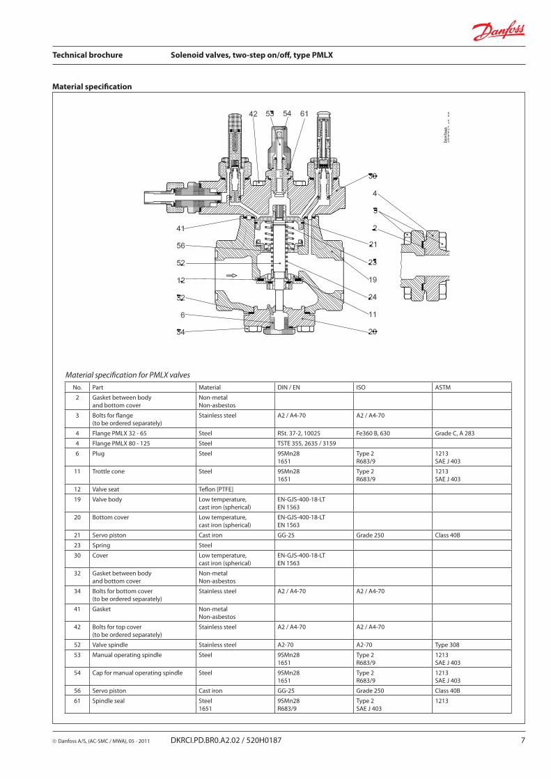
Material specification
Material specification for PMLX valves
No. Part Material DIN / EN ISO ASTM
2 Gasket between body and bottom cover
Non-metalNon-asbestos
3 Bolts for flange(to be ordered separately)
Stainless steel A2 / A4-70 A2 / A4-70
4 Flange PMLX 32 - 65 Steel RSt. 37-2, 10025 Fe360 B, 630 Grade C, A 283
4 Flange PMLX 80 - 125 Steel TSTE 355, 2635 / 3159
6 Plug Steel 9SMn281651
Type 2R683/9
1213SAE J 403
11 Trottle cone Steel 9SMn281651
Type 2R683/9
1213SAE J 403
12 Valve seat Teflon [PTFE]
19 Valve body Low temperature,cast iron (spherical)
EN-GJS-400-18-LTEN 1563
20 Bottom cover Low temperature,cast iron (spherical)
EN-GJS-400-18-LTEN 1563
21 Servo piston Cast iron GG-25 Grade 250 Class 40B
23 Spring Steel
30 Cover Low temperature,cast iron (spherical)
EN-GJS-400-18-LTEN 1563
32 Gasket between body and bottom cover
Non-metalNon-asbestos
34 Bolts for bottom cover(to be ordered separately)
Stainless steel A2 / A4-70 A2 / A4-70
41 Gasket Non-metalNon-asbestos
42 Bolts for top cover(to be ordered separately)
Stainless steel A2 / A4-70 A2 / A4-70
52 Valve spindle Stainless steel A2-70 A2-70 Type 308
53 Manual operating spindle Steel 9SMn281651
Type 2R683/9
1213SAE J 403
54 Cap for manual operating spindle Steel 9SMn281651
Type 2R683/9
1213SAE J 403
56 Servo piston Cast iron GG-25 Grade 250 Class 40B
61 Spindle seal Steel1651
9SMn28R683/9
Type 2SAE J 403
1213

8 DKRCI.PD.BR0.A2.02 / 520H0187 Danfoss A/S, (AC-SMC / MWA), 05 - 2011
Technical brochure Solenoid valves, two-step on/off, type PMLX
Flange connections Danfoss flange sets inclusive of gaskets, bolts and nuts, are specially made for the Danfoss product range and must only be used for the purpose described.When ordering PMLX valves, select the connection flanges from the list of standard flanges below. (The code numbers are for one set of two flanges).
The required PMLX valves can then be selected with or without pilot valves.
PMLX 80 to PMLX 125 can also be ordered complete with DIN weld flanges by separate code number.
NOTE: The flanges sets are exclusive gaskets, bolts and nuts.
ANSI
SOC
DIN
For use with valve typeSizemm
Sizein.
ODmm
Tmm
ODin.
Tin.
Flangetype
Code no.
Butt welding DIN (2448)
PMLX 323240
11/4
11/2
42.448.3
2.62.6
1.6691.902
0.1020.103
10027N2332027N2340
PMLX 404050
11/2
248.360.3
2.62.9
19022.370
0.1030.110
11027N2440027N2450
PMLX 505065
221/2
60.376.1
2.92.9
2.3703.000
0.1100.110
12027N2550027N2565
PMLX 656580
21/2
376.188.9
2.93.2
3.0003.500
0.1100.130
13027N2665027N2680
PMLX 80 100 4 114.3 3.6 4.500 0.140 14A 027F2123
PMLX 100 125 5 139.7 4.0 5.500 0.160 14B 027F2124
PMLX 125 150 6 168.3 4.5 6.630 0.180 14C 027F2125
For use with valve typeSizemm
Sizein.
ODmm
Tmm
ODin.
Tin.
Flange type
Schedule Code no.
Butt welding ANSI B 36.10
PMLX 323240
11/4
11/2
42.448.3
4.95.1
1.6691.902
0.1930.201
108080
027N3034027N3035
PMLX 404050
11/2
248.360.3
5.13.9
1.9022.370
0.2010.150
118040
027N3036027N3037
PMLX 505065
221/2
60.373.0
3.95.2
2.3702.870
0.1500.200
124040
027N3038027N3039
PMLX 656580
21/2
373.088.9
5.25.5
2.8703.500
0.2000.220
134040
027N3040027N3041
PMLX 80 100 4 114.3 6.0 4.500 0.240 14A 40 027N3042
PMLX 100 125 5 141.3 6.6 5.560 0.260 14B 40 027N3043
PMLX 125 150 6 168.3 7.1 6.630 0.280 14C 40 027N3044
For use with valve typeSizemm
Sizein.
IDmm
Tmm
IDin.
Tin.
Lmm
Lin.
Flangetype
Code no.
Socket welding ANSI (B 16.11)PMLX 32 32 11/4 42.7 6.05 1.681 0.238 13 0.512 10 027N2003
PMLX 40 40 11/2 48.8 6.35 1.921 0.250 13 0.512 11 027N2004
PMLX 50 50 2 61.2 6.95 2.409 0.274 16 0.630 12 027N2005
PMLX 65 65 21/2 74.0 8.75 2.913 0.344 16 0.630 13 027N2006

Danfoss A/S, (AC-SMC / MWA), 05 - 2011 DKRCI.PD.BR0.A2.02 / 520H0187 9
Technical brochure Solenoid valves, two-step on/off, type PMLX
Flange connections
SA
For use with valve typeSizemm
Sizein.
IDmm
IDin.
Lmm
Lin.
Flange type
Code no.
Soldering DIN (2856)PMLX 32 35 35.07 25 10 027L2335
PMLX 40 42 42.09 28 11 027L2442
PMLX 50 54 54.09 33 12 027L2554
PMLX 65 76 76.1 33 13 027L2676
Soldering (ANSI B 16.22)PMLX 32 13/8 1.375 0.984 10 027L2335
PMLX 40 15/8 1.625 1.102 11 027L2441
PMLX 50 21/8 2.125 1.300 12 027L2554
PMLX 65 25/8 2.625 1.300 13 027L2666
10 DKRCI.PD.BR0.A2.02 / 520H0187 Danfoss A/S, (AC-SMC / MWA), 05 - 2011
Technical brochure Solenoid valves, two-step on/off, type PMLX
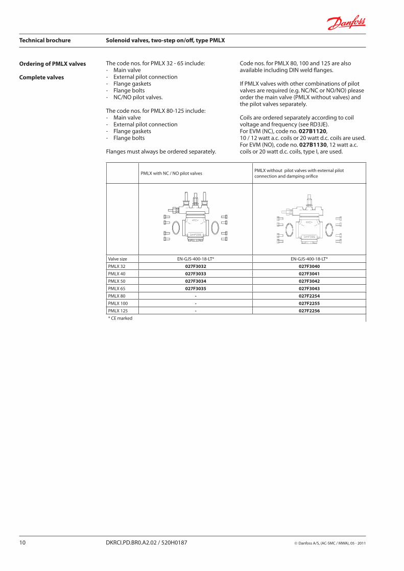
Ordering of PMLX valves
Complete valves
The code nos. for PMLX 32 - 65 include:- Main valve- External pilot connection - Flange gaskets- Flange bolts - NC/NO pilot valves.
The code nos. for PMLX 80-125 include:- Main valve - External pilot connection- Flange gaskets- Flange bolts
Flanges must always be ordered separately.
Code nos. for PMLX 80, 100 and 125 are also available including DIN weld flanges.
If PMLX valves with other combinations of pilot valves are required (e.g. NC/NC or NO/NO) please order the main valve (PMLX without valves) and the pilot valves separately.
Coils are ordered separately according to coil voltage and frequency (see RD3JE).For EVM (NC), code no. 027B1120, 10 / 12 watt a.c. coils or 20 watt d.c. coils are used.For EVM (NO), code no. 027B1130, 12 watt a.c. coils or 20 watt d.c. coils, type I, are used.
PMLX with NC / NO pilot valvesPMLX without pilot valves with external pilot connection and damping orifice
Valve size EN-GJS-400-18-LT* EN-GJS-400-18-LT*
PMLX 32 027F3032 027F3040
PMLX 40 027F3033 027F3041
PMLX 50 027F3034 027F3042
PMLX 65 027F3035 027F3043
PMLX 80 - 027F2254
PMLX 100 - 027F2255
PMLX 125 - 027F2256
* CE marked
Danfoss A/S, (AC-SMC / MWA), 05 - 2011 DKRCI.PD.BR0.A2.02 / 520H0187 11
Technical brochure Solenoid valves, two-step on/off, type PMLX
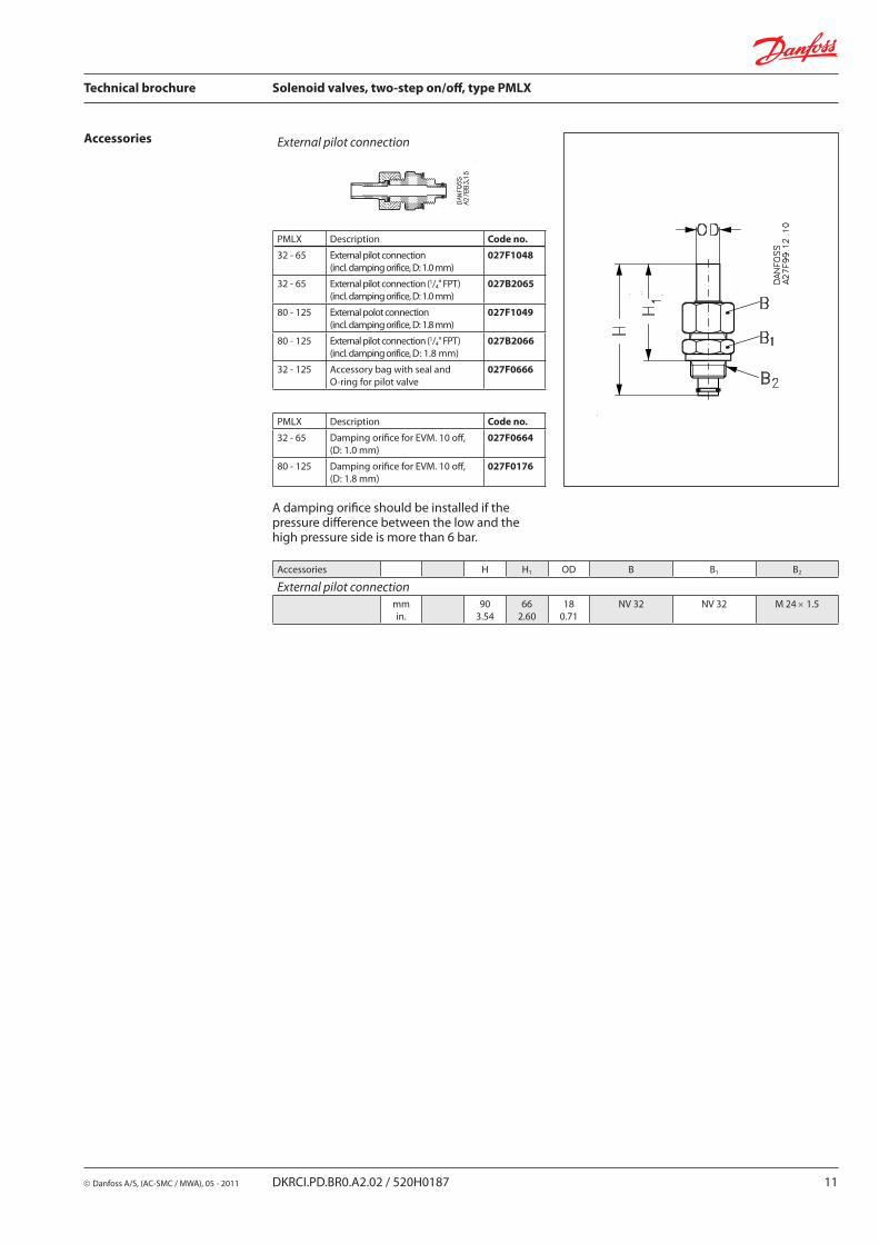
Accessories External pilot connection
PMLX Description Code no.
32 - 65 External pilot connection (incl. damping orifice, D: 1.0 mm)
027F1048
32 - 65 External pilot connection (1/4" FPT) (incl. damping orifice, D: 1.0 mm)
027B2065
80 - 125 External polot connection(incl. damping orifice, D: 1.8 mm)
027F1049
80 - 125 External pilot connection (1/4" FPT) (incl. damping orifice, D: 1.8 mm)
027B2066
32 - 125 Accessory bag with seal and O-ring for pilot valve
027F0666
PMLX Description Code no.
32 - 65 Damping orifice for EVM. 10 off, (D: 1.0 mm)
027F0664
80 - 125 Damping orifice for EVM. 10 off,(D: 1.8 mm)
027F0176
Accessories H H1 OD B B1 B2
External pilot connection mm
in.90
3.5466
2.6018
0.71NV 32 NV 32 M 24 × 1.5
A damping orifice should be installed if the pressure difference between the low and the high pressure side is more than 6 bar.
12 DKRCI.PD.BR0.A2.02 / 520H0187 Danfoss A/S, (AC-SMC / MWA), 05 - 2011
Technical brochure Solenoid valves, two-step on/off, type PMLX
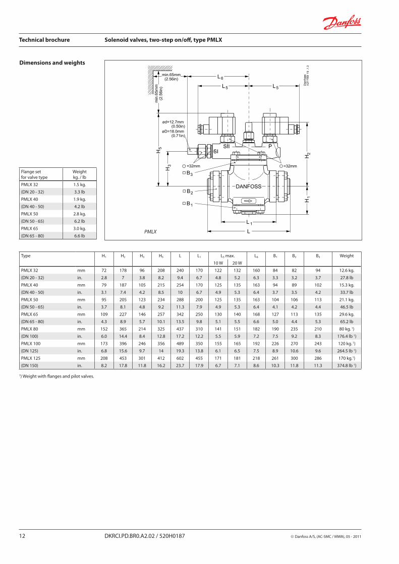
Dimensions and weights
PMLX
Type H1 H2 H3 H5 L L1 L5 max. L6 B1 B2 B3 Weight
10 W 20 W
PMLX 32 mm 72 178 96 208 240 170 122 132 160 84 82 94 12.6 kg.
(DN 20 - 32) in. 2.8 7 3.8 8.2 9.4 6.7 4.8 5.2 6.3 3.3 3.2 3.7 27.8 lb
PMLX 40 mm 79 187 105 215 254 170 125 135 163 94 89 102 15.3 kg.
(DN 40 - 50) in. 3.1 7.4 4.2 8.5 10 6.7 4.9 5.3 6.4 3.7 3.5 4.2 33.7 lb
PMLX 50 mm 95 205 123 234 288 200 125 135 163 104 106 113 21.1 kg.
(DN 50 - 65) in. 3.7 8.1 4.8 9.2 11.3 7.9 4.9 5.3 6.4 4.1 4.2 4.4 46.5 lb
PMLX 65 mm 109 227 146 257 342 250 130 140 168 127 113 135 29.6 kg.
(DN 65 - 80) in. 4.3 8.9 5.7 10.1 13.5 9.8 5.1 5.5 6.6 5.0 4.4 5.3 65.2 lb
PMLX 80 mm 152 365 214 325 437 310 141 151 182 190 235 210 80 kg. 1)
(DN 100) in. 6.0 14.4 8.4 12.8 17.2 12.2 5.5 5.9 7.2 7.5 9.2 8.3 176.4 lb 1)
PMLX 100 mm 173 396 246 356 489 350 155 165 192 226 270 243 120 kg. 1)
(DN 125) in. 6.8 15.6 9.7 14 19.3 13.8 6.1 6.5 7.5 8.9 10.6 9.6 264.5 lb 1)
PMLX 125 mm 208 453 301 412 602 455 171 181 218 261 300 286 170 kg.1)
(DN 150) in. 8.2 17.8 11.8 16.2 23.7 17.9 6.7 7.1 8.6 10.3 11.8 11.3 374.8 lb 1)
Flange setfor valve type
Weightkg. / lb
PMLX 32 1.5 kg.
(DN 20 - 32) 3.3 lb
PMLX 40 1.9 kg.
(DN 40 - 50) 4.2 lb
PMLX 50 2.8 kg.
(DN 50 - 65) 6.2 lb
PMLX 65 3.0 kg.
(DN 65 - 80) 6.6 lb
1) Weight with flanges and pilot valves.
Danfoss A/S, (AC-SMC / MWA), 05 - 2011 DKRCI.PD.BR0.A2.02 / 520H0187 13
Technical brochure Solenoid valves, two-step on/off, type PMLX
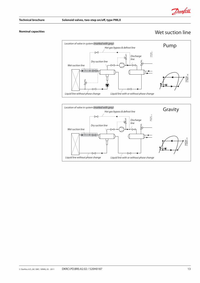
Nominal capacities Wet suction line
PumpLocation of valve in system (marked with grey)
Hot gas bypass & defrost line
Discharge line
Wet suction line
Dry suction line
Liquid line without phase change Liquid line with or without phase change
GravityLocation of valve in system (marked with grey)
Hot gas bypass & defrost line
Discharge line
Wet suction line
Dry suction line
Liquid line without phase change Liquid line with or without phase change
14 DKRCI.PD.BR0.A2.02 / 520H0187 Danfoss A/S, (AC-SMC / MWA), 05 - 2011
Technical brochure Solenoid valves, two-step on/off, type PMLX
Nominal capacities Wet suction line
SI units
US units
Calculation example (R 717 capacities):
Running conditions in a plant are as follows:
Te = –20°C Q0 = 100 kW Circulation ratio = 3 Max. ∆P = 0.1 bar
The capacity table is based on nominal conditions (pressure drop ∆P = 0.05 bar, circulation ratio = 4).
The actual capacity must therefore be corrected to a nominal condition by multiplication with correction factors.
Correction factor for ∆P = 0.1 bar, f∆P = 0.71Correction factor for circulation ratio, fcirc = 0.9
Qn = Q0 × f∆P × fcirc = 100 x 0.71 x 0.9 = 63.9 kW.
From the capacity table a PMLX 50 with Qn = 85 kW is the correct selection for the application.
Calculation example (R 717 capacities):
Running conditions in a plant are as follows:
Te = – 20°F Q0 = 10 TR Circulation ratio = 3 Max. ∆P = 1.25 psi
The capacity table is based on nominal conditions (pressure drop ∆P = 0.75 psi, circulation ratio = 4).
The actual capacity must therefore be corrected to a nominal condition by multiplication with correction factors.
Correction factor for ∆P = 1.25 psi, f∆p = 0.77Correction factor for circulation ratio, fcirc = 0.9
Qn = Q0 × f∆P × fcirc = 10 × 0.77 × 0.9 = 6.9 TR
From the capacity table a PMLX 32 with Qn = 9.7 TR is the correct selection for the application.

Danfoss A/S, (AC-SMC / MWA), 05 - 2011 DKRCI.PD.BR0.A2.02 / 520H0187 15
Technical brochure Solenoid valves, two-step on/off, type PMLX
Nominal capacities Wet suction line
SI units
US units
Capacity table for nominal conditions, QN [kW], circulation ratio = 4, ∆P = 0.05 bar
Capacity table for nominal conditions, QN [Tons of Refrigeration], circulation ratio = 4,∆P = 0.75 psi
Correction factor for circulation ratio (fcirc)
Circulation ratio
Correction factor
2 0.77
3 0.90
4 1
6 1.13
8 1.20
10 1.25
R 717Type kv
m3/h Evaporating temperature Te
–50°C –40°C –30°C –20°C –10°C 0°C 10°C 20°C
PMLX 32 22.4 20.5 27 33 40 48 56 64 73
PMLX 40 29.4 27 35 43 53 63 73 84 96
PMLX 50 47.8 44 57 70 85 102 119 137 156
PMLX 65 80.3 73 95 118 143 171 200 231 262
PMLX 80 170 155 201 250 304 362 424 488 555
PMLX 100 242 221 286 356 432 515 603 695 790
PMLX 125 385 352 456 566 688 820 959 1106 1256
Correction factor for ∆P (f∆P)
∆P (bar) Correction factor
0.01 2.24
0.03 1.29
0.05 1
0.08 0.79
0.10 0.71
0.14 0.60
R 717Type Cv
USgal/min Evaporating temperature Te
–60°F* –40°F –20°F 0°F 20°F 40°F 60°F 80°F
PMLX 32 26.0 5.7 7.7 9.7 12.1 14.6 17.2 20 23
PMLX 40 34.1 7.5 10.0 12.7 15.9 19 23 26 30
PMLX 50 55.4 12.2 16.3 21 26 31 37 42 48
PMLX 65 93 20 27 35 43 52 62 71 81
PMLX 80 197 43 58 74 92 111 131 151 172
PMLX 100 281 62 83 105 131 157 186 215 245
PMLX 125 447 98 132 167 208 250 296 342 390
* 2°F below min. operating temperature.
Correction factor for ∆P (f∆P)
∆P (psi) Correction factor
0.15 2.24
0.45 1.29
0.75 1
1.25 0.77
1.75 0.65
2.25 0.58
Correction factor forcirculation ratio (fcirc)
Circulationratio
Correctionfactor
2 0.77
3 0.90
4 1
6 1.13
8 1.20
10 1.25
16 DKRCI.PD.BR0.A2.02 / 520H0187 Danfoss A/S, (AC-SMC / MWA), 05 - 2011
Technical brochure Solenoid valves, two-step on/off, type PMLX
Nominal capacities
SI units
US units
Capacity table for nominal conditions, QN [kW], circulation ratio = 4, ∆P = 0.05 bar
Capacity table for nominal conditions, QN [Tons of Refrigeration], circulation ratio = 4, ∆P = 0.75 psi
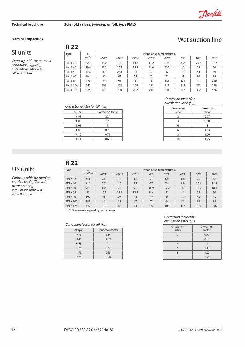
Wet suction lineR 22Type kv
m3/h Evaporating temperature Te
–50°C –40°C –30°C –20°C –10°C 0°C 10°C 20°C
PMLX 32 22.4 10.0 12.2 14.7 17.2 19.8 22.5 25.2 27.7
PMLX 40 29.4 13.1 16.1 19.2 22.6 26.0 30 33 36
PMLX 50 47.8 21.3 26.1 31 37 42 48 54 59
PMLX 65 80.3 36 44 53 62 71 81 90 99
PMLX 80 170 76 93 111 131 151 171 191 210
PMLX 100 242 108 132 158 186 214 243 272 299
PMLX 125 385 172 210 252 296 341 387 432 476
Correction factor for ∆P (f∆P)
∆P (bar) Correction factor
0.01 2.24
0.03 1.29
0.05 1
0.08 0.79
0.10 0.71
0.14 0.60
Correction factor for circulation ratio (fcirc)
Circulation ratio
Correction factor
2 0.77
3 0.90
4 1
6 1.13
8 1.20
10 1.25
Correction factor for ∆P (f∆P)
∆P (psi) Correction factor
0.15 2.24
0.45 1.29
0.75 1
1.25 0.77
1.75 0.65
2.25 0.58
Correction factor forcirculation ratio (fcirc)
Circulationratio
Correctionfactor
2 0.77
3 0.90
4 1
6 1.13
8 1.20
10 1.25
R 22Type Cv
USgal/min Evaporating temperature Te
–60°F* –40°F –20°F 0°F 20°F 40°F 60°F 80°F
PMLX 32 26.0 2.8 3.5 4.3 5.1 6.0 6.8 7.7 8.5
PMLX 40 34.1 3.7 4.6 5.7 6.7 7.8 8.9 10.1 11.2
PMLX 50 55.4 6.0 7.5 9.2 10.9 12.7 14.5 16.5 18.1
PMLX 65 93 10.1 12.7 15.4 18.4 21 24 28 30
PMLX 80 197 21 27 33 39 45 52 59 65
PMLX 100 281 30 38 47 55 64 74 83 92
PMLX 125 447 48 61 74 88 102 117 133 146
* 2°F below min. operating temperature.
Danfoss A/S, (AC-SMC / MWA), 05 - 2011 DKRCI.PD.BR0.A2.02 / 520H0187 17
Technical brochure Solenoid valves, two-step on/off, type PMLX
Nominal capacities
SI units
US units
Capacity table for nominal conditions, QN [kW], circulation ratio = 4, ∆P = 0.05 bar
Capacity table for nominal conditions, QN [Tons of Refrigeration], circulation ratio = 4, ∆P = 0.75 psi
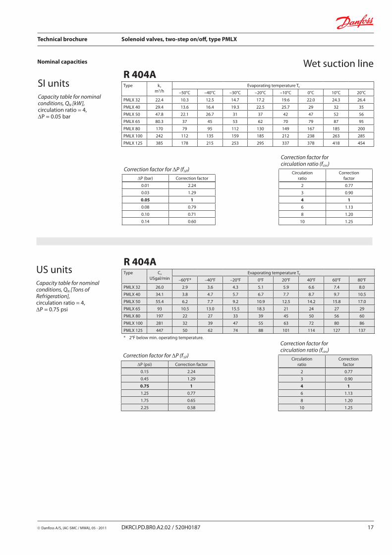
Wet suction lineR 404AType kv
m3/h Evaporating temperature Te
–50°C –40°C –30°C –20°C –10°C 0°C 10°C 20°C
PMLX 32 22.4 10.3 12.5 14.7 17.2 19.6 22.0 24.3 26.4
PMLX 40 29.4 13.6 16.4 19.3 22.5 25.7 29 32 35
PMLX 50 47.8 22.1 26.7 31 37 42 47 52 56
PMLX 65 80.3 37 45 53 62 70 79 87 95
PMLX 80 170 79 95 112 130 149 167 185 200
PMLX 100 242 112 135 159 185 212 238 263 285
PMLX 125 385 178 215 253 295 337 378 418 454
Correction factor for ∆P (f∆P)
∆P (bar) Correction factor
0.01 2.24
0.03 1.29
0.05 1
0.08 0.79
0.10 0.71
0.14 0.60
Correction factor for circulation ratio (fcirc)
Circulation ratio
Correction factor
2 0.77
3 0.90
4 1
6 1.13
8 1.20
10 1.25
Correction factor for ∆P (f∆P)
∆P (psi) Correction factor
0.15 2.24
0.45 1.29
0.75 1
1.25 0.77
1.75 0.65
2.25 0.58
Correction factor forcirculation ratio (fcirc)
Circulationratio
Correctionfactor
2 0.77
3 0.90
4 1
6 1.13
8 1.20
10 1.25
R 404AType Cv
USgal/min Evaporating temperature Te
–60°F* –40°F –20°F 0°F 20°F 40°F 60°F 80°F
PMLX 32 26.0 2.9 3.6 4.3 5.1 5.9 6.6 7.4 8.0
PMLX 40 34.1 3.8 4.7 5.7 6.7 7.7 8.7 9.7 10.5
PMLX 50 55.4 6.2 7.7 9.2 10.9 12.5 14.2 15.8 17.0
PMLX 65 93 10.5 13.0 15.5 18.3 21 24 27 29
PMLX 80 197 22 27 33 39 45 50 56 60
PMLX 100 281 32 39 47 55 63 72 80 86
PMLX 125 447 50 62 74 88 101 114 127 137
* 2°F below min. operating temperature.
18 DKRCI.PD.BR0.A2.02 / 520H0187 Danfoss A/S, (AC-SMC / MWA), 05 - 2011
Technical brochure Solenoid valves, two-step on/off, type PMLX
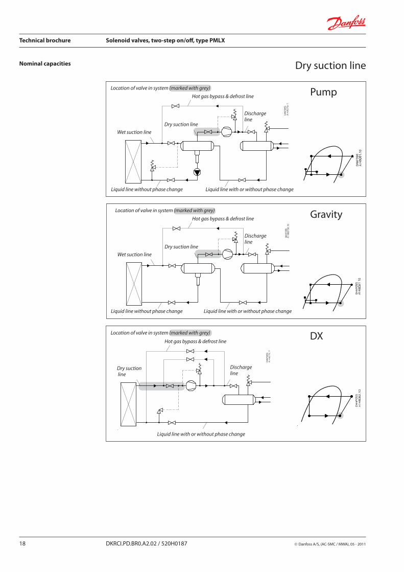
Nominal capacities Dry suction line
PumpLocation of valve in system (marked with grey)
Hot gas bypass & defrost line
Discharge line
Wet suction line
Dry suction line
Liquid line without phase change Liquid line with or without phase change
GravityLocation of valve in system (marked with grey)
Hot gas bypass & defrost line
Discharge line
Wet suction line
Dry suction line
Liquid line without phase change Liquid line with or without phase change
DXLocation of valve in system (marked with grey)
Hot gas bypass & defrost line
Discharge line
Liquid line with or without phase change
Dry suction line

Danfoss A/S, (AC-SMC / MWA), 05 - 2011 DKRCI.PD.BR0.A2.02 / 520H0187 19
Technical brochure Solenoid valves, two-step on/off, type PMLX
Nominal capacities Dry suction line
SI units
US units
Calculation example (R 717 capacities):
Running conditions in a plant are as follows:
Te = –20°C Q0 = 100 kW Tliq = 10°C Max. ∆P = 0.1 bar
The capacity table is based on nominal conditions (pressure drop ∆P = 0.05 bar, Tliq = 30°C).
The actual capacity must therefore be corrected to a nominal condition by multiplication with correction factors.
Correction factor for ∆P = 0.1 bar, f∆P = 0.71Correction factor for liquid temperature, fTliq = 0.92
Correction factor for superheat (Ts) = 1.0Qn = Q0 × f∆P × fTliq × fTs
= 100 × 0.71 × 0.92 × 1.0 = 65.3 kW
From the capacity table a PMLX 40 with Qn = 81 kW is the correct selection for the application.
Calculation example (R 717 capacities):
Running conditions in a plant are as follows:
Te = 0°F Q0 = 30 TR Tliq = 50°F Max. ∆P = 1.25 psi
The capacity table is based on nominal conditions (pressure drop ∆P = 0.75 psi, Tliq = 90°F)
The actual capacity must therefore be corrected to a nominal condition by multiplication with correction factors.
Correction factor for ∆P = 1.25 psi, f∆p = 0.77Correction factor for liquid temperature, fTliq = 0.92
Correction factor for superheat (Ts) = 1.0Qn = Q0 × f∆P × fTliq × fTs = 30 × 0.77 × 0.92 × 1.0 = 21.25 TR
From the capacity table a PMLX 40 with Qn = 24 TR is the correct selection for the application.
20 DKRCI.PD.BR0.A2.02 / 520H0187 Danfoss A/S, (AC-SMC / MWA), 05 - 2011
Technical brochure Solenoid valves, two-step on/off, type PMLX
Nominal capacities Dry suction line
SI units
US units
Capacity table for nominal conditions, QN [kW], Tliq = 30°C, ∆P = 0.05 bar
Capacity table for nominal conditions, QN [Tons of Refrigeration], Tliq = 90°F, ∆P = 0.75 psi
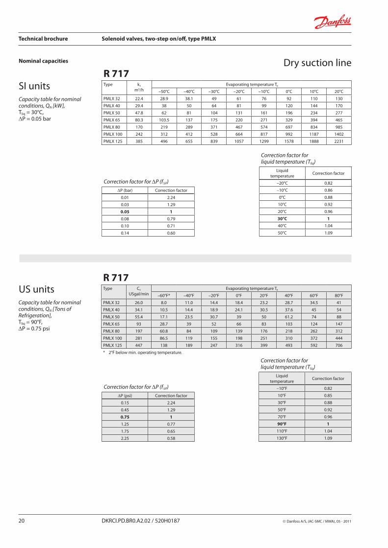
R 717Type kv
m3/h Evaporating temperature Te
–50°C –40°C –30°C –20°C –10°C 0°C 10°C 20°C
PMLX 32 22.4 28.9 38.1 49 61 76 92 110 130
PMLX 40 29.4 38 50 64 81 99 120 144 170
PMLX 50 47.8 62 81 104 131 161 196 234 277
PMLX 65 80.3 103.5 137 175 220 271 329 394 465
PMLX 80 170 219 289 371 467 574 697 834 985
PMLX 100 242 312 412 528 664 817 992 1187 1402
PMLX 125 385 496 655 839 1057 1299 1578 1888 2231
Correction factor for ∆P (f∆P)
∆P (bar) Correction factor
0.01 2.24
0.03 1.29
0.05 1
0.08 0.79
0.10 0.71
0.14 0.60
Correction factor for liquid temperature (Tliq)
Liquidtemperature
Correction factor
–20°C 0.82
–10°C 0.86
0°C 0.88
10°C 0.92
20°C 0.96
30°C 1
40°C 1.04
50°C 1.09
R 717Type Cv
USgal/min Evaporating temperature Te
–60°F* –40°F –20°F 0°F 20°F 40°F 60°F 80°F
PMLX 32 26.0 8.0 11.0 14.4 18.4 23.2 28.7 34.5 41
PMLX 40 34.1 10.5 14.4 18.9 24.1 30.5 37.6 45 54
PMLX 50 55.4 17.1 23.5 30.7 39 50 61.2 74 88
PMLX 65 93 28.7 39 52 66 83 103 124 147
PMLX 80 197 60.8 84 109 139 176 218 262 312
PMLX 100 281 86.5 119 155 198 251 310 372 444
PMLX 125 447 138 189 247 316 399 493 592 706
* 2°F below min. operating temperature.
Correction factor for ∆P (f∆P)
∆P (psi) Correction factor
0.15 2.24
0.45 1.29
0.75 1
1.25 0.77
1.75 0.65
2.25 0.58
Correction factor for liquid temperature (Tliq)
Liquidtemperature
Correction factor
–10°F 0.82
10°F 0.85
30°F 0.88
50°F 0.92
70°F 0.96
90°F 1
110°F 1.04
130°F 1.09
Danfoss A/S, (AC-SMC / MWA), 05 - 2011 DKRCI.PD.BR0.A2.02 / 520H0187 21
Technical brochure Solenoid valves, two-step on/off, type PMLX
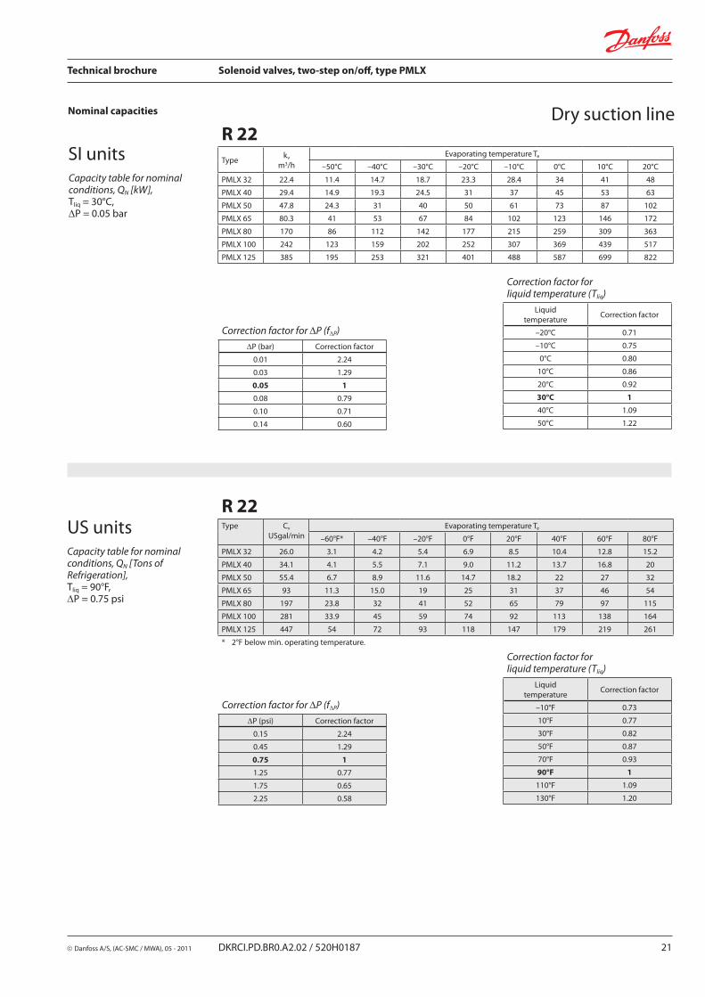
Nominal capacities Dry suction line
SI units
US units
Capacity table for nominal conditions, QN [kW], Tliq = 30°C, ∆P = 0.05 bar
Capacity table for nominal conditions, QN [Tons of Refrigeration], Tliq = 90°F, ∆P = 0.75 psi
R 22Type
kv
m3/h Evaporating temperature Te
–50°C –40°C –30°C –20°C –10°C 0°C 10°C 20°C
PMLX 32 22.4 11.4 14.7 18.7 23.3 28.4 34 41 48
PMLX 40 29.4 14.9 19.3 24.5 31 37 45 53 63
PMLX 50 47.8 24.3 31 40 50 61 73 87 102
PMLX 65 80.3 41 53 67 84 102 123 146 172
PMLX 80 170 86 112 142 177 215 259 309 363
PMLX 100 242 123 159 202 252 307 369 439 517
PMLX 125 385 195 253 321 401 488 587 699 822
Correction factor for liquid temperature (Tliq)
Liquidtemperature
Correction factor
–20°C 0.71
–10°C 0.75
0°C 0.80
10°C 0.86
20°C 0.92
30°C 1
40°C 1.09
50°C 1.22
R 22Type Cv
USgal/min Evaporating temperature Te
–60°F* –40°F –20°F 0°F 20°F 40°F 60°F 80°F
PMLX 32 26.0 3.1 4.2 5.4 6.9 8.5 10.4 12.8 15.2
PMLX 40 34.1 4.1 5.5 7.1 9.0 11.2 13.7 16.8 20
PMLX 50 55.4 6.7 8.9 11.6 14.7 18.2 22 27 32
PMLX 65 93 11.3 15.0 19 25 31 37 46 54
PMLX 80 197 23.8 32 41 52 65 79 97 115
PMLX 100 281 33.9 45 59 74 92 113 138 164
PMLX 125 447 54 72 93 118 147 179 219 261
* 2°F below min. operating temperature.
Correction factor for liquid temperature (Tliq)
Liquidtemperature
Correction factor
–10°F 0.73
10°F 0.77
30°F 0.82
50°F 0.87
70°F 0.93
90°F 1
110°F 1.09
130°F 1.20
Correction factor for ∆P (f∆P)
∆P (bar) Correction factor
0.01 2.24
0.03 1.29
0.05 1
0.08 0.79
0.10 0.71
0.14 0.60
Correction factor for ∆P (f∆P)
∆P (psi) Correction factor
0.15 2.24
0.45 1.29
0.75 1
1.25 0.77
1.75 0.65
2.25 0.58

22 DKRCI.PD.BR0.A2.02 / 520H0187 Danfoss A/S, (AC-SMC / MWA), 05 - 2011
Technical brochure Solenoid valves, two-step on/off, type PMLX
Nominal capacities Dry suction line
SI units
US units
Capacity table for nominal conditions, QN [kW], Tliq = 30°C, ∆P = 0.05 bar
Capacity table for nominal conditions, QN [Tons of Refrigeration], Tliq = 90°F, ∆P = 0.75 psi
Correction factor for liquid temperature (Tliq)
Liquidtemperature
Correction factor
–20°C 0.66
–10°C 0.70
0°C 0.76
10°C 0.82
20°C 0.90
30°C 1
40°C 1.13
50°C 1.29
R 134aType kv
m3/h Evaporating temperature Te
–50°C –40°C –30°C –20°C –10°C 0°C 10°C 20°C
PMLX 32 22.4 9.7 12.8 16.6 21 26 32 39
PMLX 40 29.4 12.7 16.8 22 27 34 42 51
PMLX 50 47.8 21 27 35 45 56 68 83
PMLX 65 80.3 35 46 60 75 94 115 139
PMLX 80 170 73 97 126 159 198 243 295
PMLX 100 242 105 138 180 226 282 346 419
PMLX 125 385 166 220 286 360 449 551 667
R 134aType Cv
USgal/min Evaporating temperature Te
–60°F* –40°F –20°F 0°F 20°F 40°F 60°F 80°F
PMLX 32 26.0 2.7 3.7 4.9 6.4 8.1 10.2 12.5
PMLX 40 34.1 3.6 4.9 6.4 8.3 10.6 13.4 16.4
PMLX 50 55.4 5.8 7.9 10.5 13.6 17.2 21.8 26.7
PMLX 65 93 9.8 13.3 17.6 23 29 37 45
PMLX 80 197 21 28 37 48 61 78 95
PMLX 100 281 30 40 53 69 87 110 135
PMLX 125 447 47 64 84 109 138 176 215
* 2°F below min. operating temperature.
Correction factor for liquid temperature (Tliq)
Liquidtemperature
Correction factor
–10°F 0.64
10°F 0.68
30°F 0.74
50°F 0.81
70°F 0.89
90°F 1
110°F 1.15
130°F 1.35
Correction factor for ∆P (f∆P)
∆P (bar) Correction factor
0.01 2.24
0.03 1.29
0.05 1
0.08 0.79
0.10 0.71
0.14 0.60
Correction factor for ∆P (f∆P)
∆P (psi) Correction factor
0.15 2.24
0.45 1.29
0.75 1
1.25 0.77
1.75 0.65
2.25 0.58

Danfoss A/S, (AC-SMC / MWA), 05 - 2011 DKRCI.PD.BR0.A2.02 / 520H0187 23
Technical brochure Solenoid valves, two-step on/off, type PMLX
Nominal capacities
Capacity table for nominal conditions, QN [kW], Tliq = 30°C, ∆P = 0.05 bar
Dry suction line
SI units
US unitsCapacity table for nominal conditions, QN [Tons of Refrigeration], Tliq = 90°F, ∆P = 0.75 psi
R 404AType kv
m3/h Evaporating temperature Te
–50°C –40°C –30°C –20°C –10°C 0°C 10°C 20°C
PMLX 32 22.4 8.6 11.4 14.9 19.2 24.0 29.6 36 43
PMLX 40 29.4 11.2 15.0 19.6 25.2 31 39 47 57
PMLX 50 47.8 18.3 24.4 32 41 51 63 77 93
PMLX 65 80.3 31 41 54 69 86 106 129 156
PMLX 80 170 65 87 113 146 182 224 274 330
PMLX 100 242 92 124 161 207 259 319 390 469
PMLX 125 385 147 197 257 330 412 508 620 747
Correction factor for liquid temperature (Tliq)
Liquidtemperature
Correction factor
–20°C 0.55
–10°C 0.60
0°C 0.66
10°C 0.74
20°C 0.85
30°C 1
40°C 1.23
50°C 1.68
Correction factor for liquid temperature (Tliq)
Liquidtemperature
Correction factor
–10°F 0.52
10°F 0.57
30°F 0.63
50°F 0.72
70°F 0.83
90°F 1
110°F 1.29
130°F 1.92
Correction factor for ∆P (f∆P)
∆P (bar) Correction factor
0.01 2.24
0.03 1.29
0.05 1
0.08 0.79
0.10 0.71
0.14 0.60
Correction factor for ∆P (f∆P)
∆P (psi) Correction factor
0.15 2.24
0.45 1.29
0.75 1
1.25 0.77
1.75 0.65
2.25 0.58
R 404AType Cv
USgal/min Evaporating temperature Te
–60°F* –40°F –20°F 0°F 20°F 40°F 60°F 80°F
PMLX 32 26.0 2.2 3.1 4.2 5.4 7.0 8.7 11.0 13.4
PMLX 40 34.1 2.9 4.1 5.4 7.1 9.1 11.5 14.5 17.6
PMLX 50 55.4 4.8 6.6 8.9 11.6 14.8 18.6 23.5 28.7
PMLX 65 93 8.0 11.4 14.9 19.5 24.9 31.3 39.5 48.1
PMLX 80 197 17.0 23.5 31.5 41.2 52.8 66.3 83.6 101.9
PMLX 100 281 24.2 33.4 44.9 58.7 75.1 94.4 119.0 145.1
PMLX 125 447 38.5 53.1 71.4 93.4 119.5 150.2 189.3 230.8
* 2°F below min. operating temperature.
24 DKRCI.PD.BR0.A2.02 / 520H0187 Danfoss A/S, (AC-SMC / MWA), 05 - 2011
Technical brochure Solenoid valves, two-step on/off, type PMLX


