Printed copies are uncontrolled copies. This version is current as of 2.25.2013.
For latest version check www.abb.com/totalflow
Doc name:
File name:
Date:
Page:
Technical bulletin 195
2104787TBAA-TB195.docx
February 26, 2013
2/17
1. Introduction
It has been discovered that not all of the released µFLOG4 and XFCG46200/6201EX units meet the published temperature accuracy specifications over the full operating temperature range. Approximately one fourth of shipped µFLOG4 units and one half of XFCG46200/6201EX units will register flowing temperature within our published specification: ±0.35°F over a normal operating range of -40°F to +140°F, (with field bias applied) excluding the uncertainty of the RTD element itself.
2. Description
The µFLOG4 and XFCG46200/6201EX units are designed to utilize a small electronic board (about the size of a stamp) that acts as an interface between the main electronics board and the internal pressure sensors and RTD input. Extensive testing has confirmed that there are two issues that adversely affect the RTD (temperature) measurement.
First, as shipped from the factory, a nominal ~2 degrees F bias may be needed on existing µFLOG4 units and ~0.5 degrees F on XFCG46200/6201EX units when first commissioning the units. We recommend that, upon installation, the temperature reading be verified against a reference temperature and the RTD bias be adjusted to agree with the reference temperature.
Second, performance outside our published specification of: ±0.35°F over a full operating range of -40°F to +140°F may be observed on some units and conditions.
Both of these issues are being corrected for new factory units. Please refer to Section 5 Supplemental Information beginning on page 15 for additional Information.
3. Is your product impacted?
Units with software versions older than those listed in the following table will require updating.
Table 3-1. Impacted products
Product Model Software: Versions to upgrade:
µFLOG4
Operating System 2104464-006 or older
FLASH (US) 2104497-012 or older
FLASH (Selectable Units) 2104498-012 or older
XFCG46200/6201EX
Operating System (16 MB) 2104154-012 or older
Operating System (32 MB) 2104447-005 or older
FLASH (US) 2104159-026 or older
FLASH (Selectable Units) 2104158-026 or older
3.1. Verifying software
1. Identify the WINCE Software Number and Flash, by connecting to the meter with PCCU. Go to the Entry Mode and choose the Registry tab. The example below shows where the Operating System and Flash part numbers are located.
Printed copies are uncontrolled copies. This version is current as of 2.25.2013.
For latest version check www.abb.com/totalflow
Doc name:
File name:
Date:
Page:
Technical bulletin 195
2104787TBAA-TB195.docx
February 26, 2013
3/17
3.2. Background on software
When the operating system is upgraded, a system cold start could result due to differences between the new OS and the previous OS. Using the procedure in this document will allow the customer to upload the tfData and restore it to the device after the OS has been replaced.
Note: It is highly recommended to collect all data and save the configuration before the following procedures.
4. Resolution A retrofit kit is available that will correct these issues for any existing µFLOG4 or XFCG46200/6201EX units. Three steps are required to properly implement the retrofit:
1. Update the OS (see table 4.1 for new versions)
2. Update the flash (see table 4.1 for new versions)
3. Insert the new cable with the resistor (Part number 2104738-001) using the following instructions depending upon the product model.
Note: ALL 3 STEPS MUST BE TAKEN in order to correct the issue. It’s especially important to note that installing the new cable without updating the flash and the OS will cause the temperature readings to be more skewed, so do not do this.
Printed copies are uncontrolled copies. This version is current as of 2.25.2013.
For latest version check www.abb.com/totalflow
Doc name:
File name:
Date:
Page:
Technical bulletin 195
2104787TBAA-TB195.docx
February 26, 2013
4/17
Table 4-1. Upgrade versions
Product Model Instructions Software: Versions to upgrade to:
µFLOG4 4.4
Operating System 2104464-007 or newer
FLASH (US) 2104497-013 or newer
FLASH (Selectable Units) 2104498-013 or newer
XFCG46200/6201EX 4.5
Operating System (16 MB) 2104154-013 or newer
Operating System (32 MB) 2104447-006 or newer
FLASH (US) 2104159-027 or newer
FLASH (Selectable Units) 2104158-027 or newer
4.1. Uploading tfData using 32Bit Loader
NOTE: It is highly recommended to collect all data and save the configuration before the following procedure.
1. Select your Device Type (FC for uFLOG4 or ExFC for EX6200/6201G4), Update mode, and select “Upload tfCold/tfData” and click “Start”. Follow the instructions on the screen, and the loader will save your data. When the Loader finishes, it will show “Operation Complete”. If this method fails, a cold start may be necessary. (This may be due to excessive corruption in the unit).
Printed copies are uncontrolled copies. This version is current as of 2.25.2013.
For latest version check www.abb.com/totalflow
Doc name:
File name:
Date:
Page:
Technical bulletin 195
2104787TBAA-TB195.docx
February 26, 2013
5/17
2. The device’s data will be placed into a subdirectory of PCCU named ‘Upload’:
3. Please note the current Network configuration and IP address of the device. If you have a different IP than the default 169.254.0.11, it will need to be re-entered, after the OS is replaced.
4.2. Upgrade the OS and Flash
When the operating system is upgraded, a system cold start could result due to differences between the new OS and the previous OS. Using this procedure will allow the customer to upload the tfData and restore it to the device after the OS has been replaced.
1. Using the 32 Bit Loader, verify correct device type is selected, select Reload and enter the new OS file in the Windows CE line and the updated Flash in the Flash line, and choose Start. (Follow the instructions on the screen). The Download will start and show a progress bar across the bottom of the screen.
2. If you are not utilizing IP connectivity for PCCU, skip to Step 6.
Printed copies are uncontrolled copies. This version is current as of 2.25.2013.
For latest version check www.abb.com/totalflow
Doc name:
File name:
Date:
Page:
Technical bulletin 195
2104787TBAA-TB195.docx
February 26, 2013
6/17
3. If you are utilizing IP connectivity for PCCU, in order to restore the IP address (after the OS and Flash are upgraded), connect to the device serially via the USB or MMI port and check or set the Network configuration.
4. The device must be reset again before the IP address will take effect. You can do this from the top level Station Setup screen by selecting System Shutdown/then Reset, choose “yes” and send:
Printed copies are uncontrolled copies. This version is current as of 2.25.2013.
For latest version check www.abb.com/totalflow
Doc name:
File name:
Date:
Page:
Technical bulletin 195
2104787TBAA-TB195.docx
February 26, 2013
7/17
5. Once the device has reset and network connectivity is established, close the screen.
6. Using the 32Bit Loader, select the Device Type and Reload Mode. Check the boxes for Shutdown Flash and Delete tfData Directory as shown below:
7. After selecting the above boxes, the following screen will appear:
8. Choose yes, then choose Start. (Follow the instructions on the screen).
9. When the data is deleted, the comment “Operation Complete” will appear.
Printed copies are uncontrolled copies. This version is current as of 2.25.2013.
For latest version check www.abb.com/totalflow
Doc name:
File name:
Date:
Page:
Technical bulletin 195
2104787TBAA-TB195.docx
February 26, 2013
8/17
4.3. Restoring tfData using 32Bit Loader
1. Verify that the proper device type is selected. Restore tfData on the device by selecting ‘Update’ mode. Check the boxes for Shutdown Flash, Restore tfCold/tfData, and Start Flash.
2. The following screen will appear: Choose Yes, then choose Start.
3. Once tfData is restored, close the 32Bit Loader and press the reset button on the board to start the unit.
4. Connect to the device using PCCU.
Printed copies are uncontrolled copies. This version is current as of 2.25.2013.
For latest version check www.abb.com/totalflow
Doc name:
File name:
Date:
Page:
Technical bulletin 195
2104787TBAA-TB195.docx
February 26, 2013
9/17
5. Choose ‘Update Cold Start Configuration’ from the top level ‘Station Setup’ Screen. Select ‘Delete and Re-Create tfCold’ option from the drop down box and Send.
Printed copies are uncontrolled copies. This version is current as of 2.25.2013.
For latest version check www.abb.com/totalflow
Doc name:
File name:
Date:
Page:
Technical bulletin 195
2104787TBAA-TB195.docx
February 26, 2013
10/17
4.4. Installing the Cable in a µFLOG4
1. Unplug all of the cables from the board except for the lithium battery (shown below). Keep the lithium battery plugged in throughout this process.
2. Remove the 3 screws and 1 hex nut shown below.
3. Remove the 6 hex nuts.
Printed copies are uncontrolled copies. This version is current as of 2.25.2013.
For latest version check www.abb.com/totalflow
Doc name:
File name:
Date:
Page:
Technical bulletin 195
2104787TBAA-TB195.docx
February 26, 2013
11/17
4. Detach the Sensor cable from the board.
5. Attach the new cable between the existing sensor cable and the electronics board.
Printed copies are uncontrolled copies. This version is current as of 2.25.2013.
For latest version check www.abb.com/totalflow
Doc name:
File name:
Date:
Page:
Technical bulletin 195
2104787TBAA-TB195.docx
February 26, 2013
12/17
6. Tuck the cable into the hole. Make sure the EMI gasket is back in place within the ridges around the hole.
7. Reassemble.
Printed copies are uncontrolled copies. This version is current as of 2.25.2013.
For latest version check www.abb.com/totalflow
Doc name:
File name:
Date:
Page:
Technical bulletin 195
2104787TBAA-TB195.docx
February 26, 2013
13/17
4.5. Installing the Cable in a 6200/6201EXG4
1. Unscrew the enclosure front cover.
2. Gently pull the face plate off the board.
3. Gently pull the board forward, taking care not to disconnect the lithium battery (circled below).
Printed copies are uncontrolled copies. This version is current as of 2.25.2013.
For latest version check www.abb.com/totalflow
Doc name:
File name:
Date:
Page:
Technical bulletin 195
2104787TBAA-TB195.docx
February 26, 2013
14/17
4. Disconnect the sensor cable from the electronics board
5. Insert the new cable between the existing sensor cable and the electronics board.
Printed copies are uncontrolled copies. This version is current as of 2.25.2013.
For latest version check www.abb.com/totalflow
Doc name:
File name:
Date:
Page:
Technical bulletin 195
2104787TBAA-TB195.docx
February 26, 2013
15/17
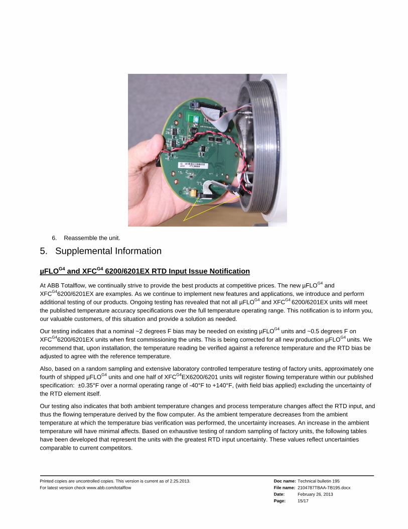
6. Reassemble the unit.
5. Supplemental Information
µFLOG4 and XFCG4 6200/6201EX RTD Input Issue Notification
At ABB Totalflow, we continually strive to provide the best products at competitive prices. The new µFLOG4 and XFCG46200/6201EX are examples. As we continue to implement new features and applications, we introduce and perform additional testing of our products. Ongoing testing has revealed that not all µFLOG4 and XFCG4 6200/6201EX units will meet the published temperature accuracy specifications over the full temperature operating range. This notification is to inform you, our valuable customers, of this situation and provide a solution as needed.
Our testing indicates that a nominal ~2 degrees F bias may be needed on existing µFLOG4 units and ~0.5 degrees F on XFCG46200/6201EX units when first commissioning the units. This is being corrected for all new production µFLOG4 units. We recommend that, upon installation, the temperature reading be verified against a reference temperature and the RTD bias be adjusted to agree with the reference temperature.
Also, based on a random sampling and extensive laboratory controlled temperature testing of factory units, approximately one fourth of shipped µFLOG4 units and one half of XFCG4EX6200/6201 units will register flowing temperature within our published specification: ±0.35°F over a normal operating range of -40°F to +140°F, (with field bias applied) excluding the uncertainty of the RTD element itself.
Our testing also indicates that both ambient temperature changes and process temperature changes affect the RTD input, and thus the flowing temperature derived by the flow computer. As the ambient temperature decreases from the ambient temperature at which the temperature bias verification was performed, the uncertainty increases. An increase in the ambient temperature will have minimal affects. Based on exhaustive testing of random sampling of factory units, the following tables have been developed that represent the units with the greatest RTD input uncertainty. These values reflect uncertainties comparable to current competitors.
Printed copies are uncontrolled copies. This version is current as of 2.25.2013.
For latest version check www.abb.com/totalflow
Doc name:
File name:
Date:
Page:
Technical bulletin 195
2104787TBAA-TB195.docx
February 26, 2013
16/17
RTD Input Performance1 for all shipped µFLOG4 units
Type: 4 wire, 100 ohm, Class B, platinum element with alpha of 0.00385
Sensing Range: -80°F to +750°F
Maximum RTD Input Uncertainty (ºF) after Temperature Bias at Process Temperature1
(including linearity, hysteresis, repeatability and ambient temperature effects)
50ºF to 80ºF ±0.77 ±0.54 ±0.46 ±0.62 ±0.77 ±0.56 ±0.76 ±0.911 Performance does not include the uncertainty of the RTD element
Printed copies are uncontrolled copies. This version is current as of 2.25.2013.
For latest version check www.abb.com/totalflow
Doc name:
File name:
Date:
Page:
Technical bulletin 195
2104787TBAA-TB195.docx
February 26, 2013
17/17
µFLOG4 and XFCG4 EX6200/6201
Design changes to correct the RTD input issue outlined above, will be implemented on all units shipped from the factory no later than February 1, 2013. A retrofit/upgrade solution will also be available by February 1, 2013 to all customers who may choose to upgrade existing units. The upgrade consists of a small adapter board/cable that connects between the existing cable from the sensor and the main electronics board as well as new software. This is a field installed solution and no data should be lost. Full instructions will accompany the upgrade components.
RTD Input Specification for all new µFLOG4 and XFCG4 EX6200/6201 units AND existing units that have had the upgrade installed
Type: 4 wire, 100 ohm, Class B, platinum element with alpha of 0.00385
Process Temperature Range: -80°F (-62ºC) to +750°F (399ºC)
Accuracy2 (including linearity, hysteresis, and repeatability): ±0.35°F (0.195ºC) within ± 250°F (140°C) of the normal operating process temperature (not to exceed Process Temperature Range limits)
Ambient Temperature Effects: not to exceed ±0.20°F (±0.12°C) per 50ºF (28ºC) change in ambient temperature
2 Accuracy specifications do not include the uncertainty of the RTD element
Conclusion
We sincerely regret any inconvenience this may cause and will provide the upgrade parts for all existing units. Please contact your local sales person, customer service, or our order entry group to obtain the upgrade. Please provide the number of units needed, shipping address, name of company and specific contact name when contacting ABB Totalflow. Depending on the number of units requested, a shipping schedule may need to be arranged.
Preferred Contact Method: Order Entry at 800-442-3097 and press 1
Barry Balzer. Product Manager, Flow Computers
6. Additional Information Totalflow product customer service 7051 Industrial Blvd. Bartlesville, OK 74006 Phone: +01 918 338 4888 (option 3) Toll Free: +01 800 442 3097 (US only)